WO2012134579A1 - Enhanced node b and method for configuring an extension carrier - Google Patents
Enhanced node b and method for configuring an extension carrier Download PDFInfo
- Publication number
- WO2012134579A1 WO2012134579A1 PCT/US2011/067622 US2011067622W WO2012134579A1 WO 2012134579 A1 WO2012134579 A1 WO 2012134579A1 US 2011067622 W US2011067622 W US 2011067622W WO 2012134579 A1 WO2012134579 A1 WO 2012134579A1
- Authority
- WO
- WIPO (PCT)
- Prior art keywords
- carrier
- radio frame
- enodeb
- extension
- extension carrier
- Prior art date
Links
- 238000000034 method Methods 0.000 title claims abstract description 21
- 238000004891 communication Methods 0.000 claims abstract description 36
- 239000000969 carrier Substances 0.000 claims description 23
- GVVPGTZRZFNKDS-JXMROGBWSA-N geranyl diphosphate Chemical compound CC(C)=CCC\C(C)=C\CO[P@](O)(=O)OP(O)(O)=O GVVPGTZRZFNKDS-JXMROGBWSA-N 0.000 claims description 10
- 230000007774 longterm Effects 0.000 claims description 9
- 230000005540 biological transmission Effects 0.000 claims description 6
- 230000002776 aggregation Effects 0.000 claims description 5
- 238000004220 aggregation Methods 0.000 claims description 5
- 230000011664 signaling Effects 0.000 abstract description 28
- 230000004044 response Effects 0.000 abstract description 5
- 238000010586 diagram Methods 0.000 description 15
- 230000004048 modification Effects 0.000 description 8
- 238000012986 modification Methods 0.000 description 8
- 230000015654 memory Effects 0.000 description 7
- 230000008901 benefit Effects 0.000 description 3
- 238000012545 processing Methods 0.000 description 3
- 238000012544 monitoring process Methods 0.000 description 2
- 230000004075 alteration Effects 0.000 description 1
- 230000009286 beneficial effect Effects 0.000 description 1
- 230000001413 cellular effect Effects 0.000 description 1
- 238000009826 distribution Methods 0.000 description 1
- 230000006872 improvement Effects 0.000 description 1
- 230000005291 magnetic effect Effects 0.000 description 1
- 238000004519 manufacturing process Methods 0.000 description 1
- 238000013507 mapping Methods 0.000 description 1
- 230000003287 optical effect Effects 0.000 description 1
- 230000008520 organization Effects 0.000 description 1
- 230000000737 periodic effect Effects 0.000 description 1
- 238000002360 preparation method Methods 0.000 description 1
- 230000008569 process Effects 0.000 description 1
- 238000013468 resource allocation Methods 0.000 description 1
- 230000003068 static effect Effects 0.000 description 1
- 230000001052 transient effect Effects 0.000 description 1
Classifications
-
- H—ELECTRICITY
- H04—ELECTRIC COMMUNICATION TECHNIQUE
- H04B—TRANSMISSION
- H04B7/00—Radio transmission systems, i.e. using radiation field
- H04B7/02—Diversity systems; Multi-antenna system, i.e. transmission or reception using multiple antennas
- H04B7/04—Diversity systems; Multi-antenna system, i.e. transmission or reception using multiple antennas using two or more spaced independent antennas
- H04B7/0413—MIMO systems
- H04B7/0456—Selection of precoding matrices or codebooks, e.g. using matrices antenna weighting
- H04B7/0486—Selection of precoding matrices or codebooks, e.g. using matrices antenna weighting taking channel rank into account
-
- H—ELECTRICITY
- H04—ELECTRIC COMMUNICATION TECHNIQUE
- H04B—TRANSMISSION
- H04B7/00—Radio transmission systems, i.e. using radiation field
- H04B7/02—Diversity systems; Multi-antenna system, i.e. transmission or reception using multiple antennas
- H04B7/04—Diversity systems; Multi-antenna system, i.e. transmission or reception using multiple antennas using two or more spaced independent antennas
- H04B7/0413—MIMO systems
- H04B7/0456—Selection of precoding matrices or codebooks, e.g. using matrices antenna weighting
-
- H—ELECTRICITY
- H04—ELECTRIC COMMUNICATION TECHNIQUE
- H04B—TRANSMISSION
- H04B7/00—Radio transmission systems, i.e. using radiation field
- H04B7/02—Diversity systems; Multi-antenna system, i.e. transmission or reception using multiple antennas
- H04B7/04—Diversity systems; Multi-antenna system, i.e. transmission or reception using multiple antennas using two or more spaced independent antennas
- H04B7/06—Diversity systems; Multi-antenna system, i.e. transmission or reception using multiple antennas using two or more spaced independent antennas at the transmitting station
- H04B7/0613—Diversity systems; Multi-antenna system, i.e. transmission or reception using multiple antennas using two or more spaced independent antennas at the transmitting station using simultaneous transmission
- H04B7/0615—Diversity systems; Multi-antenna system, i.e. transmission or reception using multiple antennas using two or more spaced independent antennas at the transmitting station using simultaneous transmission of weighted versions of same signal
- H04B7/0619—Diversity systems; Multi-antenna system, i.e. transmission or reception using multiple antennas using two or more spaced independent antennas at the transmitting station using simultaneous transmission of weighted versions of same signal using feedback from receiving side
- H04B7/0621—Feedback content
- H04B7/0632—Channel quality parameters, e.g. channel quality indicator [CQI]
-
- H—ELECTRICITY
- H04—ELECTRIC COMMUNICATION TECHNIQUE
- H04B—TRANSMISSION
- H04B7/00—Radio transmission systems, i.e. using radiation field
- H04B7/02—Diversity systems; Multi-antenna system, i.e. transmission or reception using multiple antennas
- H04B7/04—Diversity systems; Multi-antenna system, i.e. transmission or reception using multiple antennas using two or more spaced independent antennas
- H04B7/06—Diversity systems; Multi-antenna system, i.e. transmission or reception using multiple antennas using two or more spaced independent antennas at the transmitting station
- H04B7/0613—Diversity systems; Multi-antenna system, i.e. transmission or reception using multiple antennas using two or more spaced independent antennas at the transmitting station using simultaneous transmission
- H04B7/0615—Diversity systems; Multi-antenna system, i.e. transmission or reception using multiple antennas using two or more spaced independent antennas at the transmitting station using simultaneous transmission of weighted versions of same signal
- H04B7/0619—Diversity systems; Multi-antenna system, i.e. transmission or reception using multiple antennas using two or more spaced independent antennas at the transmitting station using simultaneous transmission of weighted versions of same signal using feedback from receiving side
- H04B7/0636—Feedback format
- H04B7/0639—Using selective indices, e.g. of a codebook, e.g. pre-distortion matrix index [PMI] or for beam selection
-
- H—ELECTRICITY
- H04—ELECTRIC COMMUNICATION TECHNIQUE
- H04L—TRANSMISSION OF DIGITAL INFORMATION, e.g. TELEGRAPHIC COMMUNICATION
- H04L25/00—Baseband systems
- H04L25/02—Details ; arrangements for supplying electrical power along data transmission lines
- H04L25/0202—Channel estimation
- H04L25/0204—Channel estimation of multiple channels
-
- H—ELECTRICITY
- H04—ELECTRIC COMMUNICATION TECHNIQUE
- H04L—TRANSMISSION OF DIGITAL INFORMATION, e.g. TELEGRAPHIC COMMUNICATION
- H04L25/00—Baseband systems
- H04L25/02—Details ; arrangements for supplying electrical power along data transmission lines
- H04L25/0202—Channel estimation
- H04L25/0224—Channel estimation using sounding signals
- H04L25/0226—Channel estimation using sounding signals sounding signals per se
-
- H—ELECTRICITY
- H04—ELECTRIC COMMUNICATION TECHNIQUE
- H04L—TRANSMISSION OF DIGITAL INFORMATION, e.g. TELEGRAPHIC COMMUNICATION
- H04L25/00—Baseband systems
- H04L25/02—Details ; arrangements for supplying electrical power along data transmission lines
- H04L25/03—Shaping networks in transmitter or receiver, e.g. adaptive shaping networks
- H04L25/03006—Arrangements for removing intersymbol interference
- H04L25/03343—Arrangements at the transmitter end
-
- H—ELECTRICITY
- H04—ELECTRIC COMMUNICATION TECHNIQUE
- H04L—TRANSMISSION OF DIGITAL INFORMATION, e.g. TELEGRAPHIC COMMUNICATION
- H04L43/00—Arrangements for monitoring or testing data switching networks
- H04L43/50—Testing arrangements
-
- H—ELECTRICITY
- H04—ELECTRIC COMMUNICATION TECHNIQUE
- H04L—TRANSMISSION OF DIGITAL INFORMATION, e.g. TELEGRAPHIC COMMUNICATION
- H04L45/00—Routing or path finding of packets in data switching networks
- H04L45/70—Routing based on monitoring results
-
- H—ELECTRICITY
- H04—ELECTRIC COMMUNICATION TECHNIQUE
- H04L—TRANSMISSION OF DIGITAL INFORMATION, e.g. TELEGRAPHIC COMMUNICATION
- H04L5/00—Arrangements affording multiple use of the transmission path
- H04L5/003—Arrangements for allocating sub-channels of the transmission path
-
- H—ELECTRICITY
- H04—ELECTRIC COMMUNICATION TECHNIQUE
- H04L—TRANSMISSION OF DIGITAL INFORMATION, e.g. TELEGRAPHIC COMMUNICATION
- H04L5/00—Arrangements affording multiple use of the transmission path
- H04L5/003—Arrangements for allocating sub-channels of the transmission path
- H04L5/0037—Inter-user or inter-terminal allocation
-
- H—ELECTRICITY
- H04—ELECTRIC COMMUNICATION TECHNIQUE
- H04L—TRANSMISSION OF DIGITAL INFORMATION, e.g. TELEGRAPHIC COMMUNICATION
- H04L5/00—Arrangements affording multiple use of the transmission path
- H04L5/0091—Signalling for the administration of the divided path, e.g. signalling of configuration information
- H04L5/0094—Indication of how sub-channels of the path are allocated
-
- H—ELECTRICITY
- H04—ELECTRIC COMMUNICATION TECHNIQUE
- H04L—TRANSMISSION OF DIGITAL INFORMATION, e.g. TELEGRAPHIC COMMUNICATION
- H04L65/00—Network arrangements, protocols or services for supporting real-time applications in data packet communication
- H04L65/60—Network streaming of media packets
- H04L65/65—Network streaming protocols, e.g. real-time transport protocol [RTP] or real-time control protocol [RTCP]
-
- H—ELECTRICITY
- H04—ELECTRIC COMMUNICATION TECHNIQUE
- H04W—WIRELESS COMMUNICATION NETWORKS
- H04W24/00—Supervisory, monitoring or testing arrangements
-
- H—ELECTRICITY
- H04—ELECTRIC COMMUNICATION TECHNIQUE
- H04W—WIRELESS COMMUNICATION NETWORKS
- H04W24/00—Supervisory, monitoring or testing arrangements
- H04W24/02—Arrangements for optimising operational condition
-
- H—ELECTRICITY
- H04—ELECTRIC COMMUNICATION TECHNIQUE
- H04W—WIRELESS COMMUNICATION NETWORKS
- H04W24/00—Supervisory, monitoring or testing arrangements
- H04W24/10—Scheduling measurement reports ; Arrangements for measurement reports
-
- H—ELECTRICITY
- H04—ELECTRIC COMMUNICATION TECHNIQUE
- H04W—WIRELESS COMMUNICATION NETWORKS
- H04W4/00—Services specially adapted for wireless communication networks; Facilities therefor
- H04W4/70—Services for machine-to-machine communication [M2M] or machine type communication [MTC]
-
- H—ELECTRICITY
- H04—ELECTRIC COMMUNICATION TECHNIQUE
- H04W—WIRELESS COMMUNICATION NETWORKS
- H04W48/00—Access restriction; Network selection; Access point selection
- H04W48/08—Access restriction or access information delivery, e.g. discovery data delivery
- H04W48/10—Access restriction or access information delivery, e.g. discovery data delivery using broadcasted information
-
- H—ELECTRICITY
- H04—ELECTRIC COMMUNICATION TECHNIQUE
- H04W—WIRELESS COMMUNICATION NETWORKS
- H04W48/00—Access restriction; Network selection; Access point selection
- H04W48/08—Access restriction or access information delivery, e.g. discovery data delivery
- H04W48/12—Access restriction or access information delivery, e.g. discovery data delivery using downlink control channel
-
- H—ELECTRICITY
- H04—ELECTRIC COMMUNICATION TECHNIQUE
- H04W—WIRELESS COMMUNICATION NETWORKS
- H04W52/00—Power management, e.g. Transmission Power Control [TPC] or power classes
- H04W52/02—Power saving arrangements
- H04W52/0209—Power saving arrangements in terminal devices
- H04W52/0212—Power saving arrangements in terminal devices managed by the network, e.g. network or access point is leader and terminal is follower
- H04W52/0216—Power saving arrangements in terminal devices managed by the network, e.g. network or access point is leader and terminal is follower using a pre-established activity schedule, e.g. traffic indication frame
-
- H—ELECTRICITY
- H04—ELECTRIC COMMUNICATION TECHNIQUE
- H04W—WIRELESS COMMUNICATION NETWORKS
- H04W52/00—Power management, e.g. Transmission Power Control [TPC] or power classes
- H04W52/04—Transmission power control [TPC]
- H04W52/06—TPC algorithms
- H04W52/14—Separate analysis of uplink or downlink
- H04W52/146—Uplink power control
-
- H—ELECTRICITY
- H04—ELECTRIC COMMUNICATION TECHNIQUE
- H04W—WIRELESS COMMUNICATION NETWORKS
- H04W52/00—Power management, e.g. Transmission Power Control [TPC] or power classes
- H04W52/04—Transmission power control [TPC]
- H04W52/18—TPC being performed according to specific parameters
-
- H—ELECTRICITY
- H04—ELECTRIC COMMUNICATION TECHNIQUE
- H04W—WIRELESS COMMUNICATION NETWORKS
- H04W72/00—Local resource management
- H04W72/04—Wireless resource allocation
- H04W72/044—Wireless resource allocation based on the type of the allocated resource
- H04W72/0453—Resources in frequency domain, e.g. a carrier in FDMA
-
- H—ELECTRICITY
- H04—ELECTRIC COMMUNICATION TECHNIQUE
- H04W—WIRELESS COMMUNICATION NETWORKS
- H04W72/00—Local resource management
- H04W72/20—Control channels or signalling for resource management
- H04W72/21—Control channels or signalling for resource management in the uplink direction of a wireless link, i.e. towards the network
-
- H—ELECTRICITY
- H04—ELECTRIC COMMUNICATION TECHNIQUE
- H04W—WIRELESS COMMUNICATION NETWORKS
- H04W72/00—Local resource management
- H04W72/20—Control channels or signalling for resource management
- H04W72/23—Control channels or signalling for resource management in the downlink direction of a wireless link, i.e. towards a terminal
-
- H—ELECTRICITY
- H04—ELECTRIC COMMUNICATION TECHNIQUE
- H04L—TRANSMISSION OF DIGITAL INFORMATION, e.g. TELEGRAPHIC COMMUNICATION
- H04L25/00—Baseband systems
- H04L25/02—Details ; arrangements for supplying electrical power along data transmission lines
- H04L25/03—Shaping networks in transmitter or receiver, e.g. adaptive shaping networks
- H04L25/03006—Arrangements for removing intersymbol interference
- H04L2025/0335—Arrangements for removing intersymbol interference characterised by the type of transmission
- H04L2025/03426—Arrangements for removing intersymbol interference characterised by the type of transmission transmission using multiple-input and multiple-output channels
-
- H—ELECTRICITY
- H04—ELECTRIC COMMUNICATION TECHNIQUE
- H04L—TRANSMISSION OF DIGITAL INFORMATION, e.g. TELEGRAPHIC COMMUNICATION
- H04L25/00—Baseband systems
- H04L25/02—Details ; arrangements for supplying electrical power along data transmission lines
- H04L25/03—Shaping networks in transmitter or receiver, e.g. adaptive shaping networks
- H04L25/03006—Arrangements for removing intersymbol interference
- H04L2025/03777—Arrangements for removing intersymbol interference characterised by the signalling
- H04L2025/03802—Signalling on the reverse channel
-
- H—ELECTRICITY
- H04—ELECTRIC COMMUNICATION TECHNIQUE
- H04L—TRANSMISSION OF DIGITAL INFORMATION, e.g. TELEGRAPHIC COMMUNICATION
- H04L25/00—Baseband systems
- H04L25/02—Details ; arrangements for supplying electrical power along data transmission lines
- H04L25/03—Shaping networks in transmitter or receiver, e.g. adaptive shaping networks
- H04L25/03006—Arrangements for removing intersymbol interference
- H04L25/03178—Arrangements involving sequence estimation techniques
- H04L25/03248—Arrangements for operating in conjunction with other apparatus
- H04L25/0328—Arrangements for operating in conjunction with other apparatus with interference cancellation circuitry
-
- H—ELECTRICITY
- H04—ELECTRIC COMMUNICATION TECHNIQUE
- H04L—TRANSMISSION OF DIGITAL INFORMATION, e.g. TELEGRAPHIC COMMUNICATION
- H04L5/00—Arrangements affording multiple use of the transmission path
- H04L5/003—Arrangements for allocating sub-channels of the transmission path
- H04L5/0048—Allocation of pilot signals, i.e. of signals known to the receiver
- H04L5/005—Allocation of pilot signals, i.e. of signals known to the receiver of common pilots, i.e. pilots destined for multiple users or terminals
-
- H—ELECTRICITY
- H04—ELECTRIC COMMUNICATION TECHNIQUE
- H04W—WIRELESS COMMUNICATION NETWORKS
- H04W28/00—Network traffic management; Network resource management
- H04W28/02—Traffic management, e.g. flow control or congestion control
- H04W28/04—Error control
-
- H—ELECTRICITY
- H04—ELECTRIC COMMUNICATION TECHNIQUE
- H04W—WIRELESS COMMUNICATION NETWORKS
- H04W72/00—Local resource management
-
- H—ELECTRICITY
- H04—ELECTRIC COMMUNICATION TECHNIQUE
- H04W—WIRELESS COMMUNICATION NETWORKS
- H04W88/00—Devices specially adapted for wireless communication networks, e.g. terminals, base stations or access point devices
- H04W88/02—Terminal devices
-
- H—ELECTRICITY
- H04—ELECTRIC COMMUNICATION TECHNIQUE
- H04W—WIRELESS COMMUNICATION NETWORKS
- H04W88/00—Devices specially adapted for wireless communication networks, e.g. terminals, base stations or access point devices
- H04W88/08—Access point devices
-
- H—ELECTRICITY
- H04—ELECTRIC COMMUNICATION TECHNIQUE
- H04W—WIRELESS COMMUNICATION NETWORKS
- H04W92/00—Interfaces specially adapted for wireless communication networks
- H04W92/16—Interfaces between hierarchically similar devices
- H04W92/20—Interfaces between hierarchically similar devices between access points
-
- Y—GENERAL TAGGING OF NEW TECHNOLOGICAL DEVELOPMENTS; GENERAL TAGGING OF CROSS-SECTIONAL TECHNOLOGIES SPANNING OVER SEVERAL SECTIONS OF THE IPC; TECHNICAL SUBJECTS COVERED BY FORMER USPC CROSS-REFERENCE ART COLLECTIONS [XRACs] AND DIGESTS
- Y02—TECHNOLOGIES OR APPLICATIONS FOR MITIGATION OR ADAPTATION AGAINST CLIMATE CHANGE
- Y02D—CLIMATE CHANGE MITIGATION TECHNOLOGIES IN INFORMATION AND COMMUNICATION TECHNOLOGIES [ICT], I.E. INFORMATION AND COMMUNICATION TECHNOLOGIES AIMING AT THE REDUCTION OF THEIR OWN ENERGY USE
- Y02D30/00—Reducing energy consumption in communication networks
- Y02D30/70—Reducing energy consumption in communication networks in wireless communication networks
Definitions
- the present disclosure relates generally to wireless communications. More particularly, the present disclosure relates to configuring an extension carrier within wireless communication systems.
- carrier aggregation is used to extend communication bandwidths of 1.4, 3, 5, 10, 15, and up to 20 megaHertz (MHz) in Release 8/9 and up to 100 MHz in Release 10.
- Such large bandwidth communication is achieved by the simultaneous aggregation of more than one component carrier, hence the term carrier aggregation, in which each carrier within the aggregated set of carriers is referred to as a component carrier.
- carrier aggregation in which each carrier within the aggregated set of carriers is referred to as a component carrier.
- up to five component carriers may be aggregated together to achieve the maximum bandwidth of 100 MHz.
- a backwards compatible carrier comprises a carrier accessible to user equipments (UEs) of all LTE releases (e.g., earlier releases such as Release 8/9 as well as the current release).
- a non- backwards compatible carrier comprises a carrier that is not accessible to UEs of LTE Release 8/9, but is accessible to UEs of Release 10 that defines such a carrier.
- Each of the backward compatible carrier and the non-backwards compatible carrier can operate as a stand-alone carrier or as part of CA as a component carrier.
- a stand-alone carrier comprises a carrier than can be used alone without other carriers to provide communication between UEs and enhanced Node Bs (eNodeBs or eNBs).
- a stand-alone carrier can provide the channels and signals of all the physical layers used by the LTE-Advanced system (e.g., physical downlink control channel (PDCCH), physical hybrid automatic repeat request (HARQ) indicator channel (PHICH), physical control format indicator channel (PCFICH), downlink synchronization signals, downlink reference signals, etc.).
- PDCCH physical downlink control channel
- HARQ physical hybrid automatic repeat request
- PHICH physical hybrid automatic repeat request
- PCFICH physical control format indicator channel
- downlink synchronization signals e.g., downlink reference signals, etc.
- An extension carrier comprises a carrier that cannot operate alone and instead must be part of CA set (must be a component carrier within a component carrier set of the CA), in which at least one of the other component carriers in the component carrier set is a stand-alone capable carrier.
- the extension carrier may be used as extended elements of the stand-alone capable carrier that is already configured or connected to the UEs.
- Extension carriers typically lack physical layer control channels or signals information or have limited broadcast capabilities compared to stand-alone carriers.
- extension carriers may not include any physical layer control channels, such as PDCCH, PHICH, or PCFICH, or lack various control signals information such as downlink synchronization signals or downlink reference signals.
- extension carrier may be provided by the stand-alone capable carrier within the CA.
- Current LTE-Advanced systems (Release 8/9/10) do not support extension carriers. Future releases may benefit from using extension carriers enhance the network efficiency for providing service (on an as-needed basis) in environments or operating conditions where additional service coverage is warranted.
- BRIEF DESCRIPTION OF THE DRAWINGS
- FIG. 1 illustrates an example (portion) of a wireless communications network according to some embodiments.
- FIG. 2 illustrates an example block diagram showing details of an eNodeB included in the wireless communications network of FIG. 1 according to some embodiments.
- FIG. 3 illustrates an example flow diagram for configuring an extension carrier using SystemlnformationBlock (SIB) type information included in at least one radio frame according to some embodiments.
- FIG. 4 illustrates an example timing diagram relating to the flow diagram of FIG. 3 according to some embodiments.
- FIG. 5 illustrates an example flow diagram for configuring an extension carrier using RRC dedicated signaling according to some embodiment
- FIG. 6 illustrates an example timing diagram relating to the flow diagram of FIG. 5 according to some embodiments.
- Each enhanced node B transmits the configuration information within the downlink subframes of at least one radio frame.
- the configuration information is provided in a downlink shared channel (DL-SCH) included in the radio frame.
- each eNodeB provides the configuration information within a radio resource control (RRC) signaling included in the radio frame to select ones of the user equipments (UEs) in response to the system load relative to the selected UE's request.
- RRC radio resource control
- FIG. 1 illustrates an example (portion) of a wireless communications network 100 according to some embodiments.
- the wireless communications network 100 comprises an evolved universal terrestrial radio access network (EUTRAN) using the 3rd Generation Partnership Project (3 GPP) long term evolution (LTE) standard.
- the wireless communications network 100 includes a first enhanced Node B (eNodeB or eNB) 102, a second eNodeB 106, and a plurality of user equipments (UEs) 116.
- the first eNodeB 102 also referred to as eNodeB 1 or a first base station
- the UEs 116 located within the first cell 104 are served by the first eNodeB 102.
- the first eNodeB 102 communicates with the UEs 116 on a first carrier frequency 112 (Fl) and optionally, one or more secondary carrier frequencies, such as a second carrier frequency 1 14 (F2).
- the first carrier frequency 112 may be associated with a stand-alone capable carrier and the second carrier frequency 1 14 may be associated with an extension carrier, in which the stand-alone capable carrier and the extension carrier are included in a component carrier set of carrier aggregation (CA).
- CA carrier set of carrier aggregation
- the second eNodeB 106 is similar to the first eNodeB 102 except that it serves a different cell from that of the first eNodeB 102.
- the second eNodeB 106 (also referred to as eNodeB2 or a second base station) serves another certain geographic area, denoted as a second cell 108.
- the UEs 116 located within the second cell 108 are served by the second eNodeB 106.
- the second eNodeB 106 communicates with the UEs 116 on the first carrier frequency 112 (Fl) and optionally, one or more secondary carrier frequencies, such as the second carrier frequency 1 14 (F2).
- the UEs 1 16 may comprise a variety of devices configured to communicate within the wireless communications network 100 including, but not limited to, cellular telephones, smart phones, tablets, laptops, desktops, personal computers, servers, personal digital assistants (PDAs), web appliances, set-top box (STB), a network router, switch, bridge, and the like.
- PDAs personal digital assistants
- STB set-top box
- the wireless communications network 100 includes more than two eNodeBs. It is also understood that each of the first and second eNodeBs 102, 106 can have more than one neighboring eNodeB. As an example, the first eNodeB 102 may have six or more neighboring eNodeBs. The first and second cells 104, 108 may or may not be immediately co-located next to each other.
- FIG. 2 illustrates an example block diagram showing details of the first eNodeB 102 according to some embodiments.
- the second eNodeB 106 is similarly configured.
- the first eNodeB 102 includes a processor 200, a memory 202, a transceiver 204, instructions 206, and other components (not shown).
- the processor 200 comprises one or more central processing units (CPUs), graphics processing units (GPUs), or both.
- the processor 200 provides processing and controlling functionalities for the first eNodeB 102.
- the memory 202 comprises one or more transient and static memory units configured to store instructions, data, setting information, and the like for the first eNodeB 102.
- the transceiver 204 comprises one or more transceivers configured to receive uplink receptions and transmit downlink transmissions with the UEs 1 16 within range of the first eNodeB 102.
- the transceiver 204 includes a multiple-input and multiple-output (MIMO) antenna to support MIMO communications.
- MIMO multiple-input and multiple-output
- the instructions 206 comprise one or more sets of instructions or software executed on a computing device (or machine) to cause such computing device (or machine) to perform any of the methodologies discussed herein.
- the instructions 206 (also referred to as computer- or machine -readable instructions) may reside, completely or at least partially, within the processor 200 and/or memory 202 during execution thereof.
- the processor 200 and memory 202 also comprise machine-readable media.
- the processor 200 executes the instructions 206 to cause operations associated with configuring an extension carrier for a given eNodeB with one or more UEs (e.g., the first eNodeB 102 with UEs 1 16) to implement use of that extension carrier within the wireless communications network 100.
- Each of the UEs 1 16 also includes one or more processer, memory, transceiver, instructions, and other components similar to that shown in FIG. 2. These components of any of the UEs 1 16 operate to be on the receiving end or complimentary to the configuration actions and information of the first eNodeB 102.
- Each of the first and second eNodeBs 102, 106 can be configured to communicate with respective UEs 1 16 using one, two, or more carriers, such as, but not limited to, up to five component carriers.
- the component carriers within a component carrier set of the CA may comprise one or more backwards compatible carriers and/or one or more non-backwards compatible carriers that is a stand-alone capable carrier and at least one extension carrier. Configuration schemes for implementing an extension carrier in the wireless communications network 100 are described below.
- a backwards compatible carrier comprises a carrier accessible to UEs 116 of all LTE releases (e.g., earlier releases such as Release 8/9 as well as the current Release 10).
- a non-backwards compatible carrier comprises a carrier that is not accessible to UEs 116 of earlier LTE Release 8/9, but is accessible to UEs 116 of the release that defines such a carrier.
- Each of the backward compatible carrier and the non-backwards compatible carrier can operate as a stand-alone carrier or as part of CA as a component carrier.
- a stand-alone carrier comprises a carrier than can be used alone without other carriers to provide communication between UEs 1 16 and at least one of the first and second eNodeBs 102, 106.
- a stand-alone carrier can provide the channels and signals of all the physical layers used by the LTE-Advanced system (e.g., physical downlink control channel (PDCCH), physical hybrid ARQ indicator channel (PHICH), physical control format indicator channel (PCFICH), downlink synchronization signals, downlink reference signals).
- PDCCH physical downlink control channel
- PHICH physical hybrid ARQ indicator channel
- PCFICH physical control format indicator channel
- An extension carrier comprises a carrier that cannot operate alone and instead must be part of CA set (must be a component carrier within a component carrier set of the CA), in which at least one of the other component carriers in the component carrier set is a stand-alone capable carrier.
- the extension carrier may be used as extended elements of the stand-alone capable carrier that is already configured or connected to the UEs 1 16.
- Extension carriers typically lack control channels or signals information or have limited broadcast capabilities compared to stand-alone carriers.
- extension carriers may not include any physical layer control channels, such as PDCCH, PHICH, or PCFICH, or lack various control signals information used for channel status information or synchronization.
- the missing information and/or capabilities of an extension carrier may be provided by the stand-alone capable carrier within the CA.
- configuration of an extension carrier for a given eNodeB is implemented using downlink cell-specific control signals/channels included in downlink subframes of one or more radio frames.
- the UEs 116 located in the first cell 104 transmit data to the first eNodeB 102 (uplink transmission) and receive data from the first eNodeB 102 (downlink
- radio frames comprising Orthogonal Frequency-Division Multiple Access (OFDMA) frames configured for time division duplex (TDD) operations or frequency division duplex (FDD) operations.
- OFDMA Orthogonal Frequency-Division Multiple Access
- TDD time division duplex
- FDD frequency division duplex
- Each of the radio frames comprises a plurality of uplink and downlink subframes, the uplink and downlink subframes configured in accordance with the uplink-downlink ratio configuration selected from among the supported uplink-downlink ratio configurations.
- the downlink subframes of at least one radio frame in accordance with a broadcast time period for the first eNodeB 102 includes one or more of the following downlink broadcast channel and control channels/signals (also referred to as downlink control signals, downlink control channels/signals, control channels/signals, control channels, or control signals):
- PSS/SSS Downlink primary/secondary synchronization signal
- PBCH Primary broadcast channel
- PCFICH Physical control format indicator channel
- PDCCH Physical downlink control channel
- PCH paging channel
- DL-SCH downlink shared channel
- uplink scheduling grant carries the uplink scheduling grant
- PHICH Physical hybrid ARQ indicator channel
- ACK hybrid ARQ acknowledge
- NAKs not acknowledge
- Paging channel broadcasts the paging information in the entire coverage area of the cell 104.
- Downlink reference signals include the cell-specific reference signals (CRS), multicast-broadcast signal frequency network (MBSFN) reference signal, UE-specific reference signals (DM-RS), positioning reference signals (PRS), and channel state information (CSI) reference signals (CSI-RS).
- CRS cell-specific reference signals
- MMSFN multicast-broadcast signal frequency network
- DM-RS UE-specific reference signals
- PRS positioning reference signals
- CSI-RS channel state information reference signals
- System information provided to the UEs 1 16 from the first eNodeB 102 is divided into the MasterlnformationBlock (MIB) and a plurality of Systemlnformation Blocks (SIBs).
- the MIB includes a limited number of essential and most frequently transmitted parameters used to acquire other information from the first cell 104.
- the MIB is transmitted on a broadcast channel (BCH).
- the plurality of SIBs includes SystemlnformationBlockTypel (SIB l), SystemInformationBlockType2 (SIB2), SystemInformationBlockType3 (SIB3), etc.
- SIBs other than SIB l are carried in Systemlnformation (SI) messages.
- mapping of SIBs to SI messages can be flexibly configured by a "schedulinglnfoList" field included in SIB 1 in accordance with the following rules: (1) each SIB is only included in a single SI message, (2) only SIBs having the same scheduling requirement (e.g., same periodicity) may be mapped to the same group of SI messages, and (3) SIB2 is mapped to the SI message that corresponds to the first entry in the list of SI messages in the
- SIB 1 "schedulinglnfoList" field included in SIB 1.
- SIB 1 One or more SI messages can be transmitted for a given periodicity. All of the SIBs
- FIG. 3 illustrates an example flow diagram 300 for configuring an extension carrier for the first eNodeB 102 using SystemlnformationBlock (SIB) type information included in at least one radio frame according to some embodiments.
- FIG. 4 illustrates an example timing diagram relating to the flow diagram 300 according to some embodiments. FIG. 3 is described below in conjunction with FIG. 4.
- the first eNodeB 102 broadcasts the MIB associated with a stand-alone capable carrier (e.g., first carrier frequency 112) to the UEs 116 within the first cell 104 (communication 402).
- the MIB is included in a BCH, and the BCH, in turn, comprises part of the downlink control
- the downlink control channels/signals are included in at least one radio frame (e.g., included within the downlink subframes of the at least one radio frame) in accordance with a broadcast time period. These radio frame(s) are transmitted by the first eNodeB 102 to the UEs 1 16.
- the first eNodeB 102 broadcasts one or more SIBs associated with the stand-alone capable carrier (e.g., operating at the first carrier frequency 1 12) to the UEs 1 16 within the first cell 104 (communications 404, 406). SIB 1 (communication 404) and SIB2, SIB3, etc.
- the SIBs are included in the DL-SCH, and the DL-SCH, in turn, comprises part of the downlink control channels/signals for the first eNodeB 102.
- These downlink control channels/signals are included in at least one radio frame (e.g., included within the downlink subframes of the at least one radio frame) in accordance with the broadcast time period.
- the radio frame(s) including MIB or the SIBs are broadcasted to a plurality of UEs 1 16 at the respective pre-determined broadcast time period.
- the first eNodeB 102 broadcasts a new (or special or additional) SIB type information relating to a configurable extension carrier to the UEs 116 (on the first carrier frequency 1 12) within the first cell 104
- the new or special SIB is referred to as
- SIBM SystemlnformationBlockTypeM
- SIBM comprises a dedicated SIB relating to the configurable extension carrier.
- SIB2, SIB3, etc. the SIBs type information that are not SIB 1 discussed above, SIBM is similarly encoded within a SI message.
- the SIBM type information is included in the DL-SCH, and the DL-SCH, in turn, comprises part of the downlink control channels/signals (in particular, the downlink system information transmitted in downlink share channels (PDSCH)) for the first eNodeB 102.
- PDSCH downlink share channels
- These relevant SIBs included in PDSCH are transmitted in at least one radio frame (e.g., included within the downlink subframes of the at least one radio frame) in accordance with the broadcast time period.
- the radio frames(s) containing such downlink control channels/signals are transmitted by the first eNodeB 102 to the UEs 1 16.
- the radio frames(s) including the MIB and/or other SIBs are broadcast to a plurality of UEs 1 16 at the respective predetermined broadcast time period.
- SIBM can be specified within the existing
- Systemlnformation Message field within the "schedulinglnfoList” field of SIB 1.
- An example “Systemlnformation Message” including specification of the new or additional SIBM is provided below. Additional details pertaining to the existing Systemlnformation Message is provided in 3GPP TS 36.331 Version 10.2.0, E-UTRA Radio Resource Control (RRC): Protocol Specification (Release 10), June 2011.
- RRC Radio Resource Control
- the SIBM can be generated to provided configuration information indicating the presence or absence of each of the downlink control channels/signals (PSCH, SSCH, PBCH, PCFICH, PDCCH, PHICH, PCH, CRS, PRS, and CSI-RS) of the particular extension carrier.
- This set of downlink control channels/signals information is also cell-specific (e.g., the first cell 104) and is broadcast on the primary/anchor cell (e.g., first carrier frequency 112), as is MIB and other SIBs (communications 402, 404, 406).
- SIBM type information is provided below.
- Blocks 302-306 are repeated each broadcast period of the first eNodeB 102.
- Broadcast periods also referred to as broadcast time periods or pre-determined time periods
- the UEs 1 16 served by the first eNodeB 102 are provided configuration information about an extension carrier, and one or more of the UEs 116 can connect to the extension carrier using the provided configuration information. Enabling support of LTE configurable extension carriers improves, among other things, network efficiency and/or performance.
- radio resource control (RRC) dedicated signaling with additional parameters relating to the configurable extension carrier is used to specify configuration information of the extension carrier.
- RRC radio resource control
- this embodiment implements a unicast downlink scheme using RRC dedicated signaling via radio frame(s) to select ones of the UEs 116 within the first cell 104.
- FIG. 5 illustrates an example flow diagram 500 for configuring an extension carrier for the first eNodeB 102 using RRC dedicated signaling according to some embodiments.
- FIG. 6 illustrates an example timing diagram for configuring the extension carrier using the RRC dedicated signaling according to some embodiments.
- FIG. 5 is described below in conjunction with FIG. 6.
- the first eNodeB 102 exchanges RRC connection signaling with the given UE 1 16 located within the first cell 104 in preparation of obtaining configurable extension carrier information.
- the RRC connection signaling (also referred to as RRC signaling to establish a RRC connection or RRC signaling to establish a connection) comprises RRCConnectionRequest, RRCConnectionSetup, and
- the given UE 1 16 first generates and transmits an RRCConnectionRequest signaling to the first eNodeB 102 to request a connection (communication 602). In response, the first eNodeB 102 transmits an RRCConnectionSetup signaling to the given UE 116, which provides information to establish a connection (communication 604). Last, the given UE 1 16 returns an RRCConnectionSetupComplete signaling to the first eNodeB 102 confirming a successful connection (communication 606). (See 3GPP TS 36.331 Version 10.2.0, E-UTRA Radio Resource Control (RRC): Protocol Specification (Release 10), June 201 1.) The RRC connection signaling information is included in downlink subframes of radio frame(s).
- Establishing such a connection occurs for a variety of reasons including, but not limited to, the given UE 1 16 being turned on within the first cell 104, the given UE 116 moves into the first cell 104 from another cell (e.g., the second cell 108), the given UE 116 loses an existing connection with the eNodeB 102 and attempts to reestablish a connection, and the like.
- the given UE 1 16 may initiate the RRCConnectionRequest signaling to obtain additional bandwidth and/or better reception. For example, poor coverage or significant interference being experienced by the given UE 1 16 may prompt the UE 116 to transmit the RRCConnectionRequest signaling.
- the first eNodeB 102 monitors the Pcell's load relative to the given UE's 1 16 request (block 504).
- the given UE's 116 request comprises the communication load associated with or attributable to the UE 116 including, but not limited to, the data volume of the UE's uplink request (e.g., loading photos to a website, sending a text message), the data volume of the UE's downlink request (e.g., downloading or watching videos, watching long videos such as full length movies, downloading an app), or other requests by the given UE 1 16 that contributes to the bandwidth limitation of the Pcell in aggregate with all the other bandwidth demands on the Pcell from other UEs 116, eNodeBs, or other components within the wireless communications network 100.
- the data volume of the UE's uplink request e.g., loading photos to a website, sending a text message
- the data volume of the UE's downlink request e.g., downloading or watching videos, watching long videos such as
- the Pcell load can also comprise the Pcell' s effective load or load capacity factoring in network conditions. For example, if there is significant interference or coverage holes present simultaneous with the given UE's 1 16 request, the Pcell's load capacity is less than it otherwise would be.
- the first eNodeB 102 determines if the given UE 116 and/or the network 100 would benefit from at least some of the UE's 116 request being fulfilled using an extension carrier based on load information associated with at least the Pcell and the given UE 1 16.
- the first eNodeB 102 may perform this monitoring step when the given UE 116 is of a sufficient release for the extension carrier to be accessible to that UE 116. For example, if the given UE 116 is an older model incapable of accessing the extension carrier, then the configuration information relating to the extension carrier need not be provided to that UE 116 even if the UE could benefit from using the extension carrier. In some instances, the older model UE may not be configured to expect or even understand extension carrier configuration information.
- the first eNodeB 102 may continue to monitor load relative to the UE request (back to block 504). Otherwise (yes branch 510), the first eNodeB 102 transmits RRC signal information relating to configuring the extension carrier to the given UE 116 in downlink subframe(s) of at least one radio frame (block 512).
- the downlink control channels/signals of the configurable extension carrier can be included in a dedicated RRC secondary cell (Scell)
- Addition/Modification signaling comprises a new (or special or additional) RRC signaling to the traditional RRC signalings specifically for the purposes of specifying the configurable extension carrier.
- An example Scell Addition/Modification signaling including the parameters of the configuration extension carrier is provided below.
- the above parameters of the configurable extension carrier comprise the same configuration information included in the SIMB type information above, the parameters indicating the presence or absence of each of the downlink control channels/signals (PSCH, SSCH, PBCH, PCFICH, PDCCH, PHICH, PCH, CRS, PPvS, and CSI-RS) of the particular extension carrier.
- the Scell Addition/Modification signaling is cell-specific (e.g., first cell 104) and is transmitted to the given UE 1 16 on the Pcell. Transmission of the Scell
- Addition/Modification signaling can be non-periodic or on an on-demand basis.
- the first eNodeB 102 After the first eNodeB 102 provides the Scell Addition/Modification signaling, the first eNodeB 102 returns to monitoring load at the block 504.
- the given UE 116 can now access the extension carrier using the received configuration parameters. Depending on the UE 116 request, access to the extension carrier may improve performance, such as faster download, more consistent download, faster upload, etc., than it otherwise would experience without the extension carrier.
- the flow diagram 500 is performed for each of the UEs 116 within the first cell 104 that is capable of accessing the extension carrier.
- FIGs. 5 and 6 are discussed above with respect to the first eNodeB 102, it is understood that the configuration encoding scheme similarly applies to the second eNodeB 106 and the other eNodeBs within the wireless communications network 100.
- blocks 504, 506 may be performed prior to block 502.
- an encoding scheme for defining the downlink control channels/signals of a configurable extension carrier within a LTE-Advanced network is disclosed.
- the downlink control channels/signals of the configurable extension carrier are included in at least one radio frame on a Pcell according to a pre-determined broadcast time period of an eNodeB.
- the downlink control channels/signals of the configurable extension carrier are encoded in a new SIB transmitted on the DL-SCH, wherein the DL-SCH is included in the downlink subframes of the radio frame.
- the downlink control channels/signals of the configurable extension carrier are included in a new RRC signaling.
- the new RRC signaling is included in at least one radio frame and is transmitted by an eNodeB on the Pcell to a particular UE within its coverage area, in response to an identified system improvement or efficiency from the particular UE using the extension carrier.
- machine-readable medium should be taken to include a single medium or multiple media (e.g., a centralized or distributed database, and/or associated caches and servers) that store the one or more sets of instructions.
- machine -readable medium shall also be taken to include any medium that is capable of storing, encoding or carrying a set of instructions for execution by the machine and that cause the machine to perform any one or more of the methodologies of the present disclosure.
- machine -readable medium shall accordingly be taken to include, but not be limited to, solid-state memories, optical and magnetic media, and carrier wave signals.
Landscapes
- Engineering & Computer Science (AREA)
- Signal Processing (AREA)
- Computer Networks & Wireless Communication (AREA)
- Power Engineering (AREA)
- Multimedia (AREA)
- Computer Security & Cryptography (AREA)
- Physics & Mathematics (AREA)
- Mathematical Physics (AREA)
- Mobile Radio Communication Systems (AREA)
Abstract
An apparatus and method for providing configuration information relating to an extension carrier within a wireless communications network is disclosed herein. In one embodiment, each enhanced node B (eNodeB) transmits the configuration information within the downlink subframes of at least one radio frame, wherein the configuration information is transmitted on the downlink shared channel (DL-SCH) included in the radio frame. In another embodiment, each eNodeB transmits the configuration information within a radio resource control (RRC) signaling included in at least one radio frame to select ones of the user equipments (UEs) in response to the system load relative to the select UE's request.
Description
ENHANCED NODE B AND METHOD FOR CONFIGURING AN EXTENSION CARRIER
CROSS-REFERENCE TO RELATED APPLICATIONS [0001] This application claims priority to U.S. Provisional Patent
Application No. 61/471,042 entitled "Advanced Wireless Communication Systems and Techniques" filed on April 1, 201 1, the content of which is incorporated herein by reference in its entirety.
TECHNICAL FIELD [0002] The present disclosure relates generally to wireless communications. More particularly, the present disclosure relates to configuring an extension carrier within wireless communication systems.
BACKGROUND
[0003] In the current 3rd Generation Partnership Project (3GPP) long term evolution (LTE)-Advanced systems, carrier aggregation (CA) is used to extend communication bandwidths of 1.4, 3, 5, 10, 15, and up to 20 megaHertz (MHz) in Release 8/9 and up to 100 MHz in Release 10. Such large bandwidth communication is achieved by the simultaneous aggregation of more than one component carrier, hence the term carrier aggregation, in which each carrier within the aggregated set of carriers is referred to as a component carrier. Under Release 10, up to five component carriers may be aggregated together to achieve the maximum bandwidth of 100 MHz.
[0004] Two types of carriers are discussed in Release 8/9/10: backwards compatible carrier in Release 8/9 and non-backwards compatible carrier in Release 8/9. (See 3 GPP TS 36.300 Version 10.4.0, E-UTRA Overall
Description (Release 10), June 2011.) A backwards compatible carrier comprises a carrier accessible to user equipments (UEs) of all LTE releases (e.g., earlier releases such as Release 8/9 as well as the current release). A non- backwards compatible carrier comprises a carrier that is not accessible to UEs of
LTE Release 8/9, but is accessible to UEs of Release 10 that defines such a carrier. Each of the backward compatible carrier and the non-backwards compatible carrier can operate as a stand-alone carrier or as part of CA as a component carrier. A stand-alone carrier comprises a carrier than can be used alone without other carriers to provide communication between UEs and enhanced Node Bs (eNodeBs or eNBs). A stand-alone carrier can provide the channels and signals of all the physical layers used by the LTE-Advanced system (e.g., physical downlink control channel (PDCCH), physical hybrid automatic repeat request (HARQ) indicator channel (PHICH), physical control format indicator channel (PCFICH), downlink synchronization signals, downlink reference signals, etc.).
[0005] An extension carrier, by contrast, comprises a carrier that cannot operate alone and instead must be part of CA set (must be a component carrier within a component carrier set of the CA), in which at least one of the other component carriers in the component carrier set is a stand-alone capable carrier. The extension carrier may be used as extended elements of the stand-alone capable carrier that is already configured or connected to the UEs. Extension carriers typically lack physical layer control channels or signals information or have limited broadcast capabilities compared to stand-alone carriers. For example, extension carriers may not include any physical layer control channels, such as PDCCH, PHICH, or PCFICH, or lack various control signals information such as downlink synchronization signals or downlink reference signals. The missing information and/or capabilities of an extension carrier may be provided by the stand-alone capable carrier within the CA. [0006] Current LTE-Advanced systems (Release 8/9/10) do not support extension carriers. Future releases may benefit from using extension carriers enhance the network efficiency for providing service (on an as-needed basis) in environments or operating conditions where additional service coverage is warranted.
BRIEF DESCRIPTION OF THE DRAWINGS
[0007] FIG. 1 illustrates an example (portion) of a wireless communications network according to some embodiments.
[0008] FIG. 2 illustrates an example block diagram showing details of an eNodeB included in the wireless communications network of FIG. 1 according to some embodiments.
[0009] FIG. 3 illustrates an example flow diagram for configuring an extension carrier using SystemlnformationBlock (SIB) type information included in at least one radio frame according to some embodiments. [0010] FIG. 4 illustrates an example timing diagram relating to the flow diagram of FIG. 3 according to some embodiments.
[0011] FIG. 5 illustrates an example flow diagram for configuring an extension carrier using RRC dedicated signaling according to some
embodiments. [0012] FIG. 6 illustrates an example timing diagram relating to the flow diagram of FIG. 5 according to some embodiments.
DETAILED DESCRIPTION
[0013] The following description is presented to enable any person skilled in the art to create and use a computer system configuration and related method and article of manufacture to provide configuration information relating to an extension carrier within a wireless communications network. Each enhanced node B (eNodeB) transmits the configuration information within the downlink subframes of at least one radio frame. In one embodiment, the configuration information is provided in a downlink shared channel (DL-SCH) included in the radio frame. In another embodiment, each eNodeB provides the configuration information within a radio resource control (RRC) signaling included in the radio frame to select ones of the user equipments (UEs) in response to the system load relative to the selected UE's request.
[0014] Various modifications to the embodiments will be readily apparent to those skilled in the art, and the generic principles defined herein may be applied to other embodiments and applications without departing from the spirit and scope of the invention. Moreover, in the following description, numerous details are set forth for the purpose of explanation. However, one of ordinary skill in the art will realize that embodiments of the invention may be practiced without the use of these specific details. In other instances, well-known structures and processes are not shown in block diagram form in order not to obscure the description of the embodiments of the invention with unnecessary detail. Thus, the present disclosure is not intended to be limited to the embodiments shown, but is to be accorded the widest scope consistent with the principles and features disclosed herein.
[0015] FIG. 1 illustrates an example (portion) of a wireless communications network 100 according to some embodiments. In one embodiment, the wireless communications network 100 comprises an evolved universal terrestrial radio access network (EUTRAN) using the 3rd Generation Partnership Project (3 GPP) long term evolution (LTE) standard. The wireless communications network 100 includes a first enhanced Node B (eNodeB or eNB) 102, a second eNodeB 106, and a plurality of user equipments (UEs) 116. [0016] The first eNodeB 102 (also referred to as eNodeB 1 or a first base station) serves a certain geographic area, denoted as a first cell 104. The UEs 116 located within the first cell 104 are served by the first eNodeB 102. The first eNodeB 102 communicates with the UEs 116 on a first carrier frequency 112 (Fl) and optionally, one or more secondary carrier frequencies, such as a second carrier frequency 1 14 (F2). In one embodiment, the first carrier frequency 112 may be associated with a stand-alone capable carrier and the second carrier frequency 1 14 may be associated with an extension carrier, in which the stand-alone capable carrier and the extension carrier are included in a component carrier set of carrier aggregation (CA). [0017] The second eNodeB 106 is similar to the first eNodeB 102 except that it serves a different cell from that of the first eNodeB 102. The second eNodeB 106 (also referred to as eNodeB2 or a second base station) serves
another certain geographic area, denoted as a second cell 108. The UEs 116 located within the second cell 108 are served by the second eNodeB 106. The second eNodeB 106 communicates with the UEs 116 on the first carrier frequency 112 (Fl) and optionally, one or more secondary carrier frequencies, such as the second carrier frequency 1 14 (F2).
[0018] The UEs 1 16 may comprise a variety of devices configured to communicate within the wireless communications network 100 including, but not limited to, cellular telephones, smart phones, tablets, laptops, desktops, personal computers, servers, personal digital assistants (PDAs), web appliances, set-top box (STB), a network router, switch, bridge, and the like.
[0019] It is understood that the wireless communications network 100 includes more than two eNodeBs. It is also understood that each of the first and second eNodeBs 102, 106 can have more than one neighboring eNodeB. As an example, the first eNodeB 102 may have six or more neighboring eNodeBs. The first and second cells 104, 108 may or may not be immediately co-located next to each other. One or more of the UEs 116 served by the first eNodeB 102 may move over time from the first cell 104 to the second cell 108, in which case the second eNodeB 106 takes over from the first eNodeB 10 (e.g., first eNodeB 102 performs hand-off operations with the second eNodeB 106 for those UEs 1 16). [0020] FIG. 2 illustrates an example block diagram showing details of the first eNodeB 102 according to some embodiments. The second eNodeB 106 is similarly configured. The first eNodeB 102 includes a processor 200, a memory 202, a transceiver 204, instructions 206, and other components (not shown). The processor 200 comprises one or more central processing units (CPUs), graphics processing units (GPUs), or both. The processor 200 provides processing and controlling functionalities for the first eNodeB 102. The memory 202 comprises one or more transient and static memory units configured to store instructions, data, setting information, and the like for the first eNodeB 102. The transceiver 204 comprises one or more transceivers configured to receive uplink receptions and transmit downlink transmissions with the UEs 1 16 within range of the first eNodeB 102. The transceiver 204 includes a multiple-input and multiple-output (MIMO) antenna to support MIMO communications.
[0021] The instructions 206 comprise one or more sets of instructions or software executed on a computing device (or machine) to cause such computing device (or machine) to perform any of the methodologies discussed herein. The instructions 206 (also referred to as computer- or machine -readable instructions) may reside, completely or at least partially, within the processor 200 and/or memory 202 during execution thereof. The processor 200 and memory 202 also comprise machine-readable media. In one embodiment, the processor 200 executes the instructions 206 to cause operations associated with configuring an extension carrier for a given eNodeB with one or more UEs (e.g., the first eNodeB 102 with UEs 1 16) to implement use of that extension carrier within the wireless communications network 100.
[0022] Each of the UEs 1 16 also includes one or more processer, memory, transceiver, instructions, and other components similar to that shown in FIG. 2. These components of any of the UEs 1 16 operate to be on the receiving end or complimentary to the configuration actions and information of the first eNodeB 102.
[0023] Each of the first and second eNodeBs 102, 106 can be configured to communicate with respective UEs 1 16 using one, two, or more carriers, such as, but not limited to, up to five component carriers. In one embodiment, the component carriers within a component carrier set of the CA may comprise one or more backwards compatible carriers and/or one or more non-backwards compatible carriers that is a stand-alone capable carrier and at least one extension carrier. Configuration schemes for implementing an extension carrier in the wireless communications network 100 are described below. [0024] A backwards compatible carrier comprises a carrier accessible to UEs 116 of all LTE releases (e.g., earlier releases such as Release 8/9 as well as the current Release 10). A non-backwards compatible carrier comprises a carrier that is not accessible to UEs 116 of earlier LTE Release 8/9, but is accessible to UEs 116 of the release that defines such a carrier. Each of the backward compatible carrier and the non-backwards compatible carrier can operate as a stand-alone carrier or as part of CA as a component carrier. A stand-alone carrier comprises a carrier than can be used alone without other carriers to
provide communication between UEs 1 16 and at least one of the first and second eNodeBs 102, 106. A stand-alone carrier can provide the channels and signals of all the physical layers used by the LTE-Advanced system (e.g., physical downlink control channel (PDCCH), physical hybrid ARQ indicator channel (PHICH), physical control format indicator channel (PCFICH), downlink synchronization signals, downlink reference signals).
[0025] An extension carrier comprises a carrier that cannot operate alone and instead must be part of CA set (must be a component carrier within a component carrier set of the CA), in which at least one of the other component carriers in the component carrier set is a stand-alone capable carrier. The extension carrier may be used as extended elements of the stand-alone capable carrier that is already configured or connected to the UEs 1 16. Extension carriers typically lack control channels or signals information or have limited broadcast capabilities compared to stand-alone carriers. For example, extension carriers may not include any physical layer control channels, such as PDCCH, PHICH, or PCFICH, or lack various control signals information used for channel status information or synchronization. The missing information and/or capabilities of an extension carrier may be provided by the stand-alone capable carrier within the CA. [0026] In one embodiment, configuration of an extension carrier for a given eNodeB is implemented using downlink cell-specific control signals/channels included in downlink subframes of one or more radio frames. The UEs 116 located in the first cell 104 transmit data to the first eNodeB 102 (uplink transmission) and receive data from the first eNodeB 102 (downlink
transmission) using radio frames comprising Orthogonal Frequency-Division Multiple Access (OFDMA) frames configured for time division duplex (TDD) operations or frequency division duplex (FDD) operations. Each of the radio frames comprises a plurality of uplink and downlink subframes, the uplink and downlink subframes configured in accordance with the uplink-downlink ratio configuration selected from among the supported uplink-downlink ratio configurations. (See 3GPP TS 36.21 1 Version 9.1.0, E-UTRA Physical Channels and Modulation (Release 9), March 2010.)
[0027] The downlink subframes of at least one radio frame (also referred to as a downlink radio subframes) in accordance with a broadcast time period for the first eNodeB 102 includes one or more of the following downlink broadcast channel and control channels/signals (also referred to as downlink control signals, downlink control channels/signals, control channels/signals, control channels, or control signals):
• Downlink primary/secondary synchronization signal (PSS/SSS), used for the initial cell search and frame synchronization.
• Primary broadcast channel (PBCH), which provides essential cell- specific system configuration information.
• Physical control format indicator channel (PCFICH), which informs the UEs 1 16 about the number of orthogonal frequency division multiple access (OFDMA) symbols used for the PDCCHs.
• Physical downlink control channel (PDCCH), which informs the UEs 116 about the resource allocation of the paging channel (PCH), downlink shared channel (DL-SCH), or carries the uplink scheduling grant.
• Physical hybrid ARQ indicator channel (PHICH), which carries the hybrid ARQ acknowledge (ACK)/not acknowledge (NAKs) in response to uplink shared channel (UL-SCH) transmissions.
• Paging channel (PCH) broadcasts the paging information in the entire coverage area of the cell 104.
• Downlink reference signals include the cell-specific reference signals (CRS), multicast-broadcast signal frequency network (MBSFN) reference signal, UE-specific reference signals (DM-RS), positioning reference signals (PRS), and channel state information (CSI) reference signals (CSI-RS).
(See 3 GPP TS 36.21 lVersion 10.3.0, E-UTRA Physical Channels and
Modulation (Release 10), September 201 1.)
[0028] System information provided to the UEs 1 16 from the first eNodeB 102 is divided into the MasterlnformationBlock (MIB) and a plurality of Systemlnformation Blocks (SIBs). The MIB includes a limited number of essential and most frequently transmitted parameters used to acquire other information from the first cell 104. The MIB is transmitted on a broadcast channel (BCH). The plurality of SIBs includes SystemlnformationBlockTypel (SIB l), SystemInformationBlockType2 (SIB2), SystemInformationBlockType3 (SIB3), etc. SIBs other than SIB l are carried in Systemlnformation (SI) messages. The mapping of SIBs to SI messages can be flexibly configured by a "schedulinglnfoList" field included in SIB 1 in accordance with the following rules: (1) each SIB is only included in a single SI message, (2) only SIBs having the same scheduling requirement (e.g., same periodicity) may be mapped to the same group of SI messages, and (3) SIB2 is mapped to the SI message that corresponds to the first entry in the list of SI messages in the
"schedulinglnfoList" field included in SIB 1. One or more SI messages can be transmitted for a given periodicity. All of the SIBs
(SystemlnformationBlockTypel and SystemInformationBlockType2, 3, 4, etc. contained in SI messages) are transmitted on the DL-SCH. Additional details pertaining to the system information are provided in 3GPP TS 36.331 Version 10.2.0, E-UTPvA Radio Resource Control (RRC): Protocol Specification (Release 10), June 2011.
[0029] FIG. 3 illustrates an example flow diagram 300 for configuring an extension carrier for the first eNodeB 102 using SystemlnformationBlock (SIB) type information included in at least one radio frame according to some embodiments. FIG. 4 illustrates an example timing diagram relating to the flow diagram 300 according to some embodiments. FIG. 3 is described below in conjunction with FIG. 4.
[0030] At a block 302, the first eNodeB 102 broadcasts the MIB associated with a stand-alone capable carrier (e.g., first carrier frequency 112) to the UEs 116 within the first cell 104 (communication 402). The MIB is included in a BCH, and the BCH, in turn, comprises part of the downlink control
channels/signals for the first eNodeB 102. The downlink control
channels/signals are included in at least one radio frame (e.g., included within the downlink subframes of the at least one radio frame) in accordance with a broadcast time period. These radio frame(s) are transmitted by the first eNodeB 102 to the UEs 1 16. [0031] Next at a block 304, the first eNodeB 102 broadcasts one or more SIBs associated with the stand-alone capable carrier (e.g., operating at the first carrier frequency 1 12) to the UEs 1 16 within the first cell 104 (communications 404, 406). SIB 1 (communication 404) and SIB2, SIB3, etc. (communication 406) can be provided to UEs 116. The SIBs are included in the DL-SCH, and the DL-SCH, in turn, comprises part of the downlink control channels/signals for the first eNodeB 102. These downlink control channels/signals are included in at least one radio frame (e.g., included within the downlink subframes of the at least one radio frame) in accordance with the broadcast time period. The radio frame(s) including MIB or the SIBs are broadcasted to a plurality of UEs 1 16 at the respective pre-determined broadcast time period.
[0032] At a block 306, the first eNodeB 102 broadcasts a new (or special or additional) SIB type information relating to a configurable extension carrier to the UEs 116 (on the first carrier frequency 1 12) within the first cell 104
(communication 408). The new or special SIB is referred to as
SystemlnformationBlockTypeM (SIBM or SIBM-rl 1). SIBM comprises a dedicated SIB relating to the configurable extension carrier. As with SIB2, SIB3, etc. (the SIBs type information that are not SIB 1) discussed above, SIBM is similarly encoded within a SI message. The SIBM type information is included in the DL-SCH, and the DL-SCH, in turn, comprises part of the downlink control channels/signals (in particular, the downlink system information transmitted in downlink share channels (PDSCH)) for the first eNodeB 102. These relevant SIBs included in PDSCH are transmitted in at least one radio frame (e.g., included within the downlink subframes of the at least one radio frame) in accordance with the broadcast time period. The radio frames(s) containing such downlink control channels/signals are transmitted by the first eNodeB 102 to the UEs 1 16. The radio frames(s) including the MIB and/or
other SIBs are broadcast to a plurality of UEs 1 16 at the respective predetermined broadcast time period.
[0033] For instance, SIBM can be specified within the existing
"Systemlnformation Message" field within the "schedulinglnfoList" field of SIB 1. An example "Systemlnformation Message" including specification of the new or additional SIBM is provided below. Additional details pertaining to the existing Systemlnformation Message is provided in 3GPP TS 36.331 Version 10.2.0, E-UTRA Radio Resource Control (RRC): Protocol Specification (Release 10), June 2011.

[0034] With the new/additional/special SIBM specified within
Systemlnformation Message, the SIBM can be generated to provided configuration information indicating the presence or absence of each of the downlink control channels/signals (PSCH, SSCH, PBCH, PCFICH, PDCCH, PHICH, PCH, CRS, PRS, and CSI-RS) of the particular extension carrier. This set of downlink control channels/signals information is also cell-specific (e.g., the first cell 104) and is broadcast on the primary/anchor cell (e.g., first carrier frequency 112), as is MIB and other SIBs (communications 402, 404, 406). As example SIBM type information is provided below.

[0035] Blocks 302-306 are repeated each broadcast period of the first eNodeB 102. Broadcast periods (also referred to as broadcast time periods or pre-determined time periods) can include, but is not limited to, an integer multiple of 80 ms. Accordingly, the UEs 1 16 served by the first eNodeB 102 are provided configuration information about an extension carrier, and one or more of the UEs 116 can connect to the extension carrier using the provided configuration information. Enabling support of LTE configurable extension carriers improves, among other things, network efficiency and/or performance.
[0036] In another embodiment, radio resource control (RRC) dedicated signaling with additional parameters relating to the configurable extension carrier is used to specify configuration information of the extension carrier. In contrast to the SIB embodiment described above - in which a new dedicated SIB relating to the configurable extension carrier is broadcast to all of the UEs 1 16 via radio frame(s) - this embodiment implements a unicast downlink scheme using RRC dedicated signaling via radio frame(s) to select ones of the UEs 116 within the first cell 104. FIG. 5 illustrates an example flow diagram 500 for configuring an extension carrier for the first eNodeB 102 using RRC dedicated signaling according to some embodiments. FIG. 6 illustrates an example timing diagram for configuring the extension carrier using the RRC dedicated signaling according to some embodiments. FIG. 5 is described below in conjunction with FIG. 6.
[0037] At a block 502, after an initial connection is established between a given UE 116 and the first eNodeB 102 on the anchor/primary cell (Pcell), e.g., the stand-alone carrier operating at the first carrier frequency 1 12, the first
eNodeB 102 exchanges RRC connection signaling with the given UE 1 16 located within the first cell 104 in preparation of obtaining configurable extension carrier information. The RRC connection signaling (also referred to as RRC signaling to establish a RRC connection or RRC signaling to establish a connection) comprises RRCConnectionRequest, RRCConnectionSetup, and
RRCConnectionSetupComplete signaling. The given UE 1 16 first generates and transmits an RRCConnectionRequest signaling to the first eNodeB 102 to request a connection (communication 602). In response, the first eNodeB 102 transmits an RRCConnectionSetup signaling to the given UE 116, which provides information to establish a connection (communication 604). Last, the given UE 1 16 returns an RRCConnectionSetupComplete signaling to the first eNodeB 102 confirming a successful connection (communication 606). (See 3GPP TS 36.331 Version 10.2.0, E-UTRA Radio Resource Control (RRC): Protocol Specification (Release 10), June 201 1.) The RRC connection signaling information is included in downlink subframes of radio frame(s).
[0038] Establishing such a connection occurs for a variety of reasons including, but not limited to, the given UE 1 16 being turned on within the first cell 104, the given UE 116 moves into the first cell 104 from another cell (e.g., the second cell 108), the given UE 116 loses an existing connection with the eNodeB 102 and attempts to reestablish a connection, and the like. In some embodiments, the given UE 1 16 may initiate the RRCConnectionRequest signaling to obtain additional bandwidth and/or better reception. For example, poor coverage or significant interference being experienced by the given UE 1 16 may prompt the UE 116 to transmit the RRCConnectionRequest signaling. [0039] Once a connection has been established, the first eNodeB 102 monitors the Pcell's load relative to the given UE's 1 16 request (block 504). The given UE's 116 request comprises the communication load associated with or attributable to the UE 116 including, but not limited to, the data volume of the UE's uplink request (e.g., loading photos to a website, sending a text message), the data volume of the UE's downlink request (e.g., downloading or watching videos, watching long videos such as full length movies, downloading an app), or other requests by the given UE 1 16 that contributes to the bandwidth
limitation of the Pcell in aggregate with all the other bandwidth demands on the Pcell from other UEs 116, eNodeBs, or other components within the wireless communications network 100. The Pcell load can also comprise the Pcell' s effective load or load capacity factoring in network conditions. For example, if there is significant interference or coverage holes present simultaneous with the given UE's 1 16 request, the Pcell's load capacity is less than it otherwise would be.
[0040] Overall, the first eNodeB 102 determines if the given UE 116 and/or the network 100 would benefit from at least some of the UE's 116 request being fulfilled using an extension carrier based on load information associated with at least the Pcell and the given UE 1 16. The first eNodeB 102 may perform this monitoring step when the given UE 116 is of a sufficient release for the extension carrier to be accessible to that UE 116. For example, if the given UE 116 is an older model incapable of accessing the extension carrier, then the configuration information relating to the extension carrier need not be provided to that UE 116 even if the UE could benefit from using the extension carrier. In some instances, the older model UE may not be configured to expect or even understand extension carrier configuration information.
[0041] If the first eNodeB 102 determines that connection to an extension carrier is not beneficial (unnecessary or otherwise not desired) for the given UE 116 (block 506, no branch 508), then the first eNodeB 102 may continue to monitor load relative to the UE request (back to block 504). Otherwise (yes branch 510), the first eNodeB 102 transmits RRC signal information relating to configuring the extension carrier to the given UE 116 in downlink subframe(s) of at least one radio frame (block 512).
[0042] The downlink control channels/signals of the configurable extension carrier can be included in a dedicated RRC secondary cell (Scell)
Addition/Modification signaling by the first eNodeB 102 and provided to the given UE 116 (communication 608). The dedicated RRC Scell
Addition/Modification signaling comprises a new (or special or additional) RRC signaling to the traditional RRC signalings specifically for the purposes of specifying the configurable extension carrier. An example Scell
Addition/Modification signaling including the parameters of the configuration extension carrier is provided below.
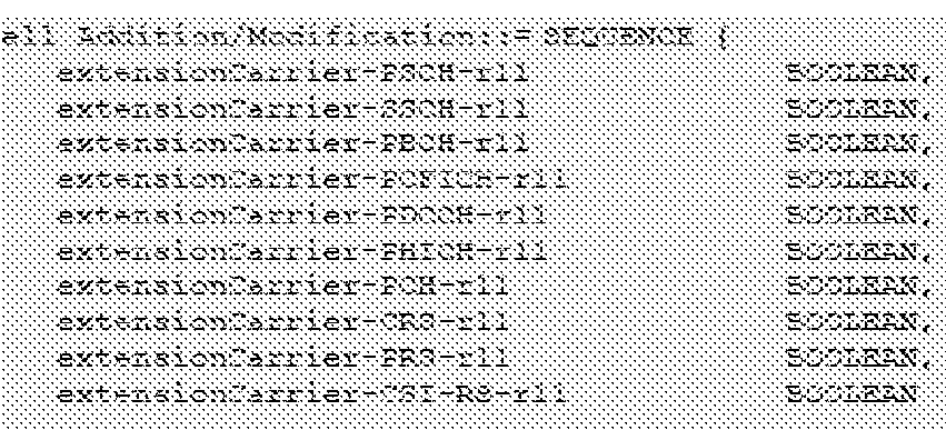
[0043] The above parameters of the configurable extension carrier comprise the same configuration information included in the SIMB type information above, the parameters indicating the presence or absence of each of the downlink control channels/signals (PSCH, SSCH, PBCH, PCFICH, PDCCH, PHICH, PCH, CRS, PPvS, and CSI-RS) of the particular extension carrier. The Scell Addition/Modification signaling is cell-specific (e.g., first cell 104) and is transmitted to the given UE 1 16 on the Pcell. Transmission of the Scell
Addition/Modification signaling can be non-periodic or on an on-demand basis.
[0044] After the first eNodeB 102 provides the Scell Addition/Modification signaling, the first eNodeB 102 returns to monitoring load at the block 504. The given UE 116 can now access the extension carrier using the received configuration parameters. Depending on the UE 116 request, access to the extension carrier may improve performance, such as faster download, more consistent download, faster upload, etc., than it otherwise would experience without the extension carrier.
[0045] The flow diagram 500 is performed for each of the UEs 116 within the first cell 104 that is capable of accessing the extension carrier. Although FIGs. 5 and 6 are discussed above with respect to the first eNodeB 102, it is understood that the configuration encoding scheme similarly applies to the second eNodeB 106 and the other eNodeBs within the wireless communications network 100. In some embodiments, blocks 504, 506 may be performed prior to block 502.
[0046] Accordingly, an encoding scheme for defining the downlink control channels/signals of a configurable extension carrier within a LTE-Advanced network is disclosed. In one embodiment, the downlink control channels/signals of the configurable extension carrier are included in at least one radio frame on a Pcell according to a pre-determined broadcast time period of an eNodeB. The downlink control channels/signals of the configurable extension carrier are encoded in a new SIB transmitted on the DL-SCH, wherein the DL-SCH is included in the downlink subframes of the radio frame. In another embodiment, the downlink control channels/signals of the configurable extension carrier are included in a new RRC signaling. The new RRC signaling is included in at least one radio frame and is transmitted by an eNodeB on the Pcell to a particular UE within its coverage area, in response to an identified system improvement or efficiency from the particular UE using the extension carrier.
[0047] The term "machine-readable medium," "computer readable medium," and the like should be taken to include a single medium or multiple media (e.g., a centralized or distributed database, and/or associated caches and servers) that store the one or more sets of instructions. The term "machine -readable medium" shall also be taken to include any medium that is capable of storing, encoding or carrying a set of instructions for execution by the machine and that cause the machine to perform any one or more of the methodologies of the present disclosure. The term "machine -readable medium" shall accordingly be taken to include, but not be limited to, solid-state memories, optical and magnetic media, and carrier wave signals.
[0048] It will be appreciated that, for clarity purposes, the above description describes some embodiments with reference to different functional units or processors. However, it will be apparent that any suitable distribution of functionality between different functional units, processors or domains may be used without detracting from embodiments of the invention. For example, functionality illustrated to be performed by separate processors or controllers may be performed by the same processor or controller. Hence, references to specific functional units are only to be seen as references to suitable means for
providing the described functionality, rather than indicative of a strict logical or physical structure or organization.
[0049] Although the present invention has been described in connection with some embodiments, it is not intended to be limited to the specific form set forth herein. One skilled in the art would recognize that various features of the described embodiments may be combined in accordance with the invention. Moreover, it will be appreciated that various modifications and alterations may be made by those skilled in the art without departing from the spirit and scope of the invention. As an example, the above scheme for configuring an extension carrier can also be used to configure a non-extension carrier (e.g., a stand-alone carrier).
[0050] The Abstract of the Disclosure is provided to comply with 37 C.F.R. § 1.72(b), requiring an abstract that will allow the reader to quickly ascertain the nature of the technical disclosure. It is submitted with the understanding that it will not be used to interpret or limit the scope or meaning of the claims. In addition, in the foregoing Detailed Description, it can be seen that various features are grouped together in a single embodiment for the purpose of streamlining the disclosure. This method of disclosure is not to be interpreted as reflecting an intention that the claimed embodiments require more features than are expressly recited in each claim. Rather, as the following claims reflect, inventive subject matter lies in less than all features of a single disclosed embodiment. Thus the following claims are hereby incorporated into the Detailed Description, with each claim standing on its own as a separate embodiment.
Claims
1. An enhanced node B (eNodeB) to operate within a wireless communications network, comprising: a processor to generate at least one radio frame including configuration parameters of an extension carrier according to a predetermined time period, wherein a system information block (SIB)-type information dedicated to the configuration parameters of the extension carrier is included in the radio frame; and a transceiver to transmit the radio frame according to the predetermined time period on a first carrier operating at a first carrier frequency, wherein the extension carrier comprises a second carrier operating at a second carrier frequency and a carrier incapable of operating without the first carrier.
2. The eNodeB of claim 1, wherein the pre-determined time period comprises a broadcast time period of the eNodeB on the first carrier.
3. The eNodeB of claim 1, wherein the configuration parameters of the extension carrier comprise downlink control signals of the extension carrier.
4. The eNodeB of claim 1, wherein the transceiver transmits the SIB-type information on a downlink shared channel (DL-SCH) included in the radio frame.
5. The eNodeB of claim 1, wherein the radio frame is structured for time division duplex (TDD) mode operation in a 3rd Generation Partnership Project (3 GPP) long term evolution (LTE) network.
6. The eNodeB of claim 1, wherein the radio frame is structured for frequency division duplex (FDD) mode operation in a 3rd Generation Partnership Project (3 GPP) long term evolution (LTE) network.
7. The eNodeB of claim 1, wherein the first carrier and the extension carrier comprise component carriers of a carrier aggreg (CA).
8. An enhanced node B (eNodeB) to operate within a wireless communications network, the eNodeB to: generate at least one radio frame including configuration parameters of an extension carrier, wherein a radio resource control (RRC) information dedicated to the configuration parameters of the extension carrier is included in the radio frame; and transmit the radio frame on a first carrier operating at a first carrier frequency to a user equipment (UE), wherein the extension carrier comprises a second carrier operating at a second carrier frequency and a carrier incapable of operating without the first carrier.
9. The eNodeB of claim 8, wherein the configuration parameters of the extension carrier comprise downlink control signals of the extension carrier.
10. The eNodeB of claim 8, wherein the eNodeB is to transmit RRC connection information to connect the eNodeB and the UE on the first carrier prior to transmission of the radio frame including the RRC information.
11. The eNodeB of claim 8, wherein the eNodeB is to generate the RRC information based on at least one of a load information associated with the first carrier and the UE.
12. The eNodeB of claim 8, wherein the wireless communications network comprises a 3rd Generation Partnership Project (3 GPP) long term evolution (LTE)-Advanced network.
13. A method for communicating configuration parameters of an extension carrier, the method comprising: transmitting, by an enhanced node B (eNodeB), at least one radio frame including the configuration parameters of the extension carrier, wherein at least one of a system information block (SIB)-type information dedicated to the configuration parameters of the extension carrier is included in the radio frame, and a radio resource control (RRC) information dedicated to the configuration parameters of the extension carrier is included in the radio frame and selectively transmitted to an user equipment (UE).
14. The method of claim 13, wherein the configuration parameters of the extension carrier comprise downlink control signals of the extension carrier.
15. The method of claim 13, wherein the transmitting of the radio frame comprises transmitting the SIB-type information on a downlink shared channel (DL-SCH) included in the radio frame.
16. The method of claim 13, wherein the radio frame is structured for time division duplex (TDD) mode operation in a 3rd Generation Partnership Project (3 GPP) long term evolution (LTE) network.
17. The method of claim 13, wherein the radio frame is structured for frequency division duplex (FDD) mode operation in a 3rd Generation Partnership Project (3 GPP) long term evolution (LTE) network.
18. The method of claim 13, wherein the transmitting of the radio frame comprises transmitting the radio frame including the RRC information subsequent to transmitting RRC connection information between the eNodeB and the UE.
19. The method of claim 13, wherein the transmitting of the radio frame comprises transmitting on a primary cell operating at a first carrier frequency.
20. The method of claim 19, further comprising determining to transmit the radio frame including the RRC information based on load information associated with at least one of the primary cell and the UE.
21. The method of claim 19, wherein the primary cell and the extension carrier comprise component carriers of a carrier aggregation (CA), the primary cell comprising a stand-alone capable carrier and the extension carrier comprising a carrier that cannot operate without the stand-alone capable carrier being included in the CA.
22. The method of claim 13, wherein the transmitting of the radio frame including the SIB-type information is transmitted in accordance with a pre-determined broadcast time period.
23. The method of claim 13, wherein the transmitting of the radio frame including the RRC information comprises transmitting to the UE having a configuration capable of accessing the extension carrier.
24. An user equipment (UE) to operate within a wireless
communications network, the UE to: receive at least one radio frame including configuration parameters of an extension carrier from a base station on a first carrier operating at a first carrier frequency, wherein the extension carrier comprises a second carrier operating at a second carrier frequency, the extension carrier unable to operate without the first carrier.
25. The UE of claim 24, wherein the radio frame includes a system information block (SIB)-type information dedicated to the configuration parameters of the extension carrier, the SIB-type information provided on a downlink shared channel (DL-SCH) of the radio frame.
26. The UE of claim 24, wherein the radio frame includes a radio resource control (RRC) information dedicated to the configuration parameters of the extension carrier.
27. The UE of claim 24, wherein the radio frame is received in accordance with a pre-determined broadcast time period.
28. The UE of claim 24, wherein the radio frame is structured for time division duplex (TDD) mode operation in a 3rd Generation Partnership Project (3 GPP) long term evolution (LTE) network.
29. The UE of claim 24, wherein the radio frame is structured for frequency division duplex (FDD) mode operation in a 3rd Generation
Partnership Project (3 GPP) long term evolution (LTE) network.
Priority Applications (4)
| Application Number | Priority Date | Filing Date | Title |
|---|---|---|---|
| CN201180071273.XA CN103583006B (en) | 2011-04-01 | 2011-12-28 | Enhancement mode node B and method for configuring extension carrier wave |
| US13/992,959 US9204369B2 (en) | 2011-04-01 | 2011-12-28 | Enhanced node B and method for configuring an extension carrier |
| EP11862568.0A EP2695314A4 (en) | 2011-04-01 | 2011-12-28 | Enhanced node b and method for configuring an extension carrier |
| PCT/US2011/067622 WO2012134579A1 (en) | 2011-04-01 | 2011-12-28 | Enhanced node b and method for configuring an extension carrier |
Applications Claiming Priority (3)
| Application Number | Priority Date | Filing Date | Title |
|---|---|---|---|
| US201161471042P | 2011-04-01 | 2011-04-01 | |
| US61/471,042 | 2011-04-01 | ||
| PCT/US2011/067622 WO2012134579A1 (en) | 2011-04-01 | 2011-12-28 | Enhanced node b and method for configuring an extension carrier |
Publications (1)
| Publication Number | Publication Date |
|---|---|
| WO2012134579A1 true WO2012134579A1 (en) | 2012-10-04 |
Family
ID=51211951
Family Applications (1)
| Application Number | Title | Priority Date | Filing Date |
|---|---|---|---|
| PCT/US2011/067622 WO2012134579A1 (en) | 2011-04-01 | 2011-12-28 | Enhanced node b and method for configuring an extension carrier |
Country Status (4)
| Country | Link |
|---|---|
| US (1) | US9204369B2 (en) |
| EP (1) | EP2695314A4 (en) |
| CN (1) | CN103583006B (en) |
| WO (1) | WO2012134579A1 (en) |
Cited By (3)
| Publication number | Priority date | Publication date | Assignee | Title |
|---|---|---|---|---|
| WO2014070411A1 (en) * | 2012-11-01 | 2014-05-08 | Alexei Davydov | Frequency offset measurement enhancements for long term evolution (lte) |
| US9204369B2 (en) | 2011-04-01 | 2015-12-01 | Intel Corporation | Enhanced node B and method for configuring an extension carrier |
| CN103973399B (en) * | 2013-01-31 | 2018-11-16 | 中兴通讯股份有限公司 | A kind of method generating carrier configuration information and network side equipment and user equipment |
Families Citing this family (17)
| Publication number | Priority date | Publication date | Assignee | Title |
|---|---|---|---|---|
| US9197390B2 (en) | 2011-08-12 | 2015-11-24 | Panasonic Intellectual Property Corporation Of America | Communication device, and retransmission control method |
| US9247542B2 (en) * | 2012-01-31 | 2016-01-26 | Apple Inc. | Methods and apparatus for efficient spectral usage in extensible carrier deployments |
| WO2014047906A1 (en) * | 2012-09-28 | 2014-04-03 | 华为技术有限公司 | Method, device and communication system for processing common search area |
| US10111049B2 (en) * | 2012-10-26 | 2018-10-23 | Qualcomm Incorporated | Multiband eMBMS enhancement using carrier aggregation |
| US9980247B2 (en) | 2012-10-26 | 2018-05-22 | Qualcomm Incorporated | Primary cell signaling for eMBMS in carrier aggregation |
| US9294885B2 (en) * | 2013-03-28 | 2016-03-22 | Tejas Networks Limited | Method and system for system information acquisition |
| CN104349491A (en) * | 2013-08-08 | 2015-02-11 | 中兴通讯股份有限公司 | PESCH (physical downlink shared channel) transmission method, system and network side equipment |
| KR102310991B1 (en) | 2014-03-26 | 2021-10-13 | 삼성전자주식회사 | Appratus and method for signaling for time division duplex-frequency division duplex carrier aggregation in wireless communication system |
| KR102218702B1 (en) | 2014-03-26 | 2021-02-22 | 삼성전자주식회사 | Appratus and method for time division duplex-frequency division duplex carrier aggregation in wireless communication system |
| WO2016118056A1 (en) * | 2015-01-21 | 2016-07-28 | Telefonaktiebolaget Lm Ericsson (Publ) | Wireless local area network access points |
| US20160219558A1 (en) * | 2015-01-22 | 2016-07-28 | Texas Instruments Incorporated | Low overhead signaling for point to multipoint nlos wireless backhaul |
| WO2016174904A1 (en) * | 2015-04-30 | 2016-11-03 | ソニー株式会社 | Communication device and communication method |
| WO2017023231A1 (en) | 2015-07-31 | 2017-02-09 | Intel Corporation | Receive beam indication for 5g systems |
| EP3533274A1 (en) * | 2016-10-28 | 2019-09-04 | Sony Corporation | Mobile telecommunications system entity for transmitting system information in a 5g network |
| BR112020019951A2 (en) * | 2018-04-06 | 2021-01-26 | Telefonaktiebolaget Lm Ericsson (Publ) | methods performed by a first wireless device to transmit a sync signal to a second wireless device and by a network node to control a first wireless device, first wireless device, network node, computer program, and, carrier . |
| US10965786B2 (en) | 2018-10-31 | 2021-03-30 | At&T Intellectual Property I, L.P. | Adaptive fixed point mapping for uplink and downlink fronthaul |
| EP4203578A4 (en) * | 2020-09-18 | 2023-10-11 | Huawei Technologies Co., Ltd. | Method and apparatus for transmitting physical downlink control channel |
Family Cites Families (8)
| Publication number | Priority date | Publication date | Assignee | Title |
|---|---|---|---|---|
| US8917598B2 (en) * | 2007-12-21 | 2014-12-23 | Qualcomm Incorporated | Downlink flow control |
| JP5291565B2 (en) * | 2008-11-04 | 2013-09-18 | 株式会社エヌ・ティ・ティ・ドコモ | Radio base station apparatus and mobile terminal apparatus |
| CN101505538A (en) * | 2009-03-13 | 2009-08-12 | 中兴通讯股份有限公司 | Method and system for multi-carrier stochastic access |
| CN101998611B (en) * | 2009-08-11 | 2013-03-27 | 华为技术有限公司 | Power control information communication method and device for uplink carrier wave |
| US20110080885A1 (en) | 2009-10-05 | 2011-04-07 | Electronics And Telecommunications Research Institute | Apparatus and method for management of extension carrier in base station |
| US9559829B2 (en) * | 2009-11-04 | 2017-01-31 | Telefonaktiebolaget Lm Ericsson (Publ) | Signaling for flexible carrier aggregation |
| CN101772179A (en) * | 2010-01-08 | 2010-07-07 | 中兴通讯股份有限公司 | Method and system for transmitting system information in carrier aggregation scene |
| WO2012134579A1 (en) | 2011-04-01 | 2012-10-04 | Intel Corporation | Enhanced node b and method for configuring an extension carrier |
-
2011
- 2011-12-28 WO PCT/US2011/067622 patent/WO2012134579A1/en active Application Filing
- 2011-12-28 US US13/992,959 patent/US9204369B2/en active Active
- 2011-12-28 EP EP11862568.0A patent/EP2695314A4/en not_active Withdrawn
- 2011-12-28 CN CN201180071273.XA patent/CN103583006B/en not_active Expired - Fee Related
Non-Patent Citations (6)
| Title |
|---|
| CMCC: "Operations of Extension Carriers in CA", 3GPP TSG RAN WG2 MEETING #68, R2-096983, 9 November 2009 (2009-11-09), XP050391359 * |
| ETRI: "SI for Extension Carrier", 3GPP TSG RAN WG2 MEETING #68, R2-096517, 9 November 2009 (2009-11-09), XP050391102 * |
| MOTOROLA: "Extension carrier operation", 3GPP TSG RAN WG2 MEETING #68, R2-096875, 9 November 2009 (2009-11-09), XP050391290 * |
| NTT DOCOMO ET AL.: "3GPP DRAFT; R2-096976, 3RD GENERATION PARTNERSHIP PROJECT (3GPP", MOBILE COMPETENCE CENTRE, article "Non-accessible carriers in LTE-A" |
| SAMSUNG: "Discussion on the extension carrier operation", 3GPP TSG RAN WG2 MEETING #68, R2-096908, 9 November 2009 (2009-11-09), XP050391316 * |
| See also references of EP2695314A4 |
Cited By (8)
| Publication number | Priority date | Publication date | Assignee | Title |
|---|---|---|---|---|
| US9204369B2 (en) | 2011-04-01 | 2015-12-01 | Intel Corporation | Enhanced node B and method for configuring an extension carrier |
| WO2014070411A1 (en) * | 2012-11-01 | 2014-05-08 | Alexei Davydov | Frequency offset measurement enhancements for long term evolution (lte) |
| US9225399B2 (en) | 2012-11-01 | 2015-12-29 | Intel Corporation | Method to enable optimization for small data in an evolved packet core (EPC) |
| US9332469B2 (en) | 2012-11-01 | 2016-05-03 | Intel Corporation | Frequency offset measurement enhancements for long term evolution (LTE) |
| US9572077B2 (en) | 2012-11-01 | 2017-02-14 | Intel Corporation | Inter-RAT mobility of in-device coexistence |
| US9838932B2 (en) | 2012-11-01 | 2017-12-05 | Intel Corporation | PCI partition and allocation for cellular network |
| US9930596B2 (en) | 2012-11-01 | 2018-03-27 | Intel Corporation | Method and apparatus for controlling small data transmission on the uplink |
| CN103973399B (en) * | 2013-01-31 | 2018-11-16 | 中兴通讯股份有限公司 | A kind of method generating carrier configuration information and network side equipment and user equipment |
Also Published As
| Publication number | Publication date |
|---|---|
| CN103583006A (en) | 2014-02-12 |
| US20140050127A1 (en) | 2014-02-20 |
| EP2695314A1 (en) | 2014-02-12 |
| US9204369B2 (en) | 2015-12-01 |
| CN103583006B (en) | 2017-06-06 |
| EP2695314A4 (en) | 2015-11-11 |
Similar Documents
| Publication | Publication Date | Title |
|---|---|---|
| US9204369B2 (en) | Enhanced node B and method for configuring an extension carrier | |
| KR102248662B1 (en) | Narrowband time-division duplex frame structure for narrowband communications | |
| JP7574233B2 (en) | UE-ASSISTED FAST TRANSITION BETWEEN RRC STATES - Patent application | |
| US20210399787A1 (en) | Default beam selection based on a subset of coresets | |
| US9730250B2 (en) | Method and user equipment for transmitting uplink signal | |
| EP3342226B1 (en) | Radio frame configuration | |
| EP3787211B1 (en) | Communication method and communication apparatus | |
| US11616633B2 (en) | Half-duplex operation in new radio frequency division duplexing bands | |
| US20210195624A1 (en) | Signaling for uplink beam activation | |
| US20220022192A1 (en) | Beam-specific parameters | |
| US20240251403A1 (en) | Power control parameters for multi-trp pusch repetition | |
| US11606821B2 (en) | Downlink transmission indication for RACH occasions | |
| WO2022246632A1 (en) | Transmission configuration indicator state applicability prior to acknowledgement | |
| US11728856B2 (en) | User equipment antenna panel distribution reporting | |
| US11881948B2 (en) | Downlink control information based feedback transmission | |
| TW202218467A (en) | Management of uplink and srs transmissions on different carriers | |
| US11778652B2 (en) | Multi component carrier (CC) scheduler | |
| US20220322298A1 (en) | Adaptation of processing timelines for high frequency bands | |
| WO2023028930A1 (en) | Multi physical uplink shared channel (pusch) scheduling for multiple transmission reception points (m-trp) | |
| TWI872255B (en) | Device and method for receiving downlink control information, and base station | |
| US20240147385A1 (en) | Power headroom reporting for uplink channel repetition | |
| WO2022246721A1 (en) | Associating beam indication with a channel state information (csi) measurement or report | |
| WO2022032511A1 (en) | Harq-process specific user equipment configuration for reduced capability complexity reduction |
Legal Events
| Date | Code | Title | Description |
|---|---|---|---|
| 121 | Ep: the epo has been informed by wipo that ep was designated in this application |
Ref document number: 11862568 Country of ref document: EP Kind code of ref document: A1 |
|
| NENP | Non-entry into the national phase |
Ref country code: DE |
|
| WWE | Wipo information: entry into national phase |
Ref document number: 2011862568 Country of ref document: EP |
|
| WWE | Wipo information: entry into national phase |
Ref document number: 13992959 Country of ref document: US |