WO2012053101A1 - Terminal device, image display method executed by terminal device, and image display program - Google Patents
Terminal device, image display method executed by terminal device, and image display program Download PDFInfo
- Publication number
- WO2012053101A1 WO2012053101A1 PCT/JP2010/068711 JP2010068711W WO2012053101A1 WO 2012053101 A1 WO2012053101 A1 WO 2012053101A1 JP 2010068711 W JP2010068711 W JP 2010068711W WO 2012053101 A1 WO2012053101 A1 WO 2012053101A1
- Authority
- WO
- WIPO (PCT)
- Prior art keywords
- image
- terminal device
- adjustment
- adjustment image
- captured
- Prior art date
Links
Images


Classifications
-
- B—PERFORMING OPERATIONS; TRANSPORTING
- B60—VEHICLES IN GENERAL
- B60R—VEHICLES, VEHICLE FITTINGS, OR VEHICLE PARTS, NOT OTHERWISE PROVIDED FOR
- B60R11/00—Arrangements for holding or mounting articles, not otherwise provided for
- B60R11/02—Arrangements for holding or mounting articles, not otherwise provided for for radio sets, television sets, telephones, or the like; Arrangement of controls thereof
-
- H—ELECTRICITY
- H04—ELECTRIC COMMUNICATION TECHNIQUE
- H04N—PICTORIAL COMMUNICATION, e.g. TELEVISION
- H04N23/00—Cameras or camera modules comprising electronic image sensors; Control thereof
- H04N23/50—Constructional details
- H04N23/51—Housings
-
- B—PERFORMING OPERATIONS; TRANSPORTING
- B60—VEHICLES IN GENERAL
- B60R—VEHICLES, VEHICLE FITTINGS, OR VEHICLE PARTS, NOT OTHERWISE PROVIDED FOR
- B60R11/00—Arrangements for holding or mounting articles, not otherwise provided for
- B60R11/04—Mounting of cameras operative during drive; Arrangement of controls thereof relative to the vehicle
-
- G—PHYSICS
- G01—MEASURING; TESTING
- G01C—MEASURING DISTANCES, LEVELS OR BEARINGS; SURVEYING; NAVIGATION; GYROSCOPIC INSTRUMENTS; PHOTOGRAMMETRY OR VIDEOGRAMMETRY
- G01C21/00—Navigation; Navigational instruments not provided for in groups G01C1/00 - G01C19/00
- G01C21/20—Instruments for performing navigational calculations
-
- G—PHYSICS
- G01—MEASURING; TESTING
- G01C—MEASURING DISTANCES, LEVELS OR BEARINGS; SURVEYING; NAVIGATION; GYROSCOPIC INSTRUMENTS; PHOTOGRAMMETRY OR VIDEOGRAMMETRY
- G01C21/00—Navigation; Navigational instruments not provided for in groups G01C1/00 - G01C19/00
- G01C21/26—Navigation; Navigational instruments not provided for in groups G01C1/00 - G01C19/00 specially adapted for navigation in a road network
- G01C21/265—Navigation; Navigational instruments not provided for in groups G01C1/00 - G01C19/00 specially adapted for navigation in a road network constructional aspects of navigation devices, e.g. housings, mountings, displays
-
- G—PHYSICS
- G01—MEASURING; TESTING
- G01C—MEASURING DISTANCES, LEVELS OR BEARINGS; SURVEYING; NAVIGATION; GYROSCOPIC INSTRUMENTS; PHOTOGRAMMETRY OR VIDEOGRAMMETRY
- G01C21/00—Navigation; Navigational instruments not provided for in groups G01C1/00 - G01C19/00
- G01C21/26—Navigation; Navigational instruments not provided for in groups G01C1/00 - G01C19/00 specially adapted for navigation in a road network
- G01C21/34—Route searching; Route guidance
- G01C21/36—Input/output arrangements for on-board computers
- G01C21/3602—Input other than that of destination using image analysis, e.g. detection of road signs, lanes, buildings, real preceding vehicles using a camera
-
- G—PHYSICS
- G01—MEASURING; TESTING
- G01C—MEASURING DISTANCES, LEVELS OR BEARINGS; SURVEYING; NAVIGATION; GYROSCOPIC INSTRUMENTS; PHOTOGRAMMETRY OR VIDEOGRAMMETRY
- G01C21/00—Navigation; Navigational instruments not provided for in groups G01C1/00 - G01C19/00
- G01C21/26—Navigation; Navigational instruments not provided for in groups G01C1/00 - G01C19/00 specially adapted for navigation in a road network
- G01C21/34—Route searching; Route guidance
- G01C21/36—Input/output arrangements for on-board computers
- G01C21/3626—Details of the output of route guidance instructions
- G01C21/3647—Guidance involving output of stored or live camera images or video streams
-
- H—ELECTRICITY
- H04—ELECTRIC COMMUNICATION TECHNIQUE
- H04N—PICTORIAL COMMUNICATION, e.g. TELEVISION
- H04N23/00—Cameras or camera modules comprising electronic image sensors; Control thereof
- H04N23/50—Constructional details
-
- H—ELECTRICITY
- H04—ELECTRIC COMMUNICATION TECHNIQUE
- H04N—PICTORIAL COMMUNICATION, e.g. TELEVISION
- H04N7/00—Television systems
- H04N7/18—Closed-circuit television [CCTV] systems, i.e. systems in which the video signal is not broadcast
- H04N7/183—Closed-circuit television [CCTV] systems, i.e. systems in which the video signal is not broadcast for receiving images from a single remote source
-
- B—PERFORMING OPERATIONS; TRANSPORTING
- B60—VEHICLES IN GENERAL
- B60R—VEHICLES, VEHICLE FITTINGS, OR VEHICLE PARTS, NOT OTHERWISE PROVIDED FOR
- B60R11/00—Arrangements for holding or mounting articles, not otherwise provided for
- B60R11/02—Arrangements for holding or mounting articles, not otherwise provided for for radio sets, television sets, telephones, or the like; Arrangement of controls thereof
- B60R11/0241—Arrangements for holding or mounting articles, not otherwise provided for for radio sets, television sets, telephones, or the like; Arrangement of controls thereof for telephones
-
- B—PERFORMING OPERATIONS; TRANSPORTING
- B60—VEHICLES IN GENERAL
- B60R—VEHICLES, VEHICLE FITTINGS, OR VEHICLE PARTS, NOT OTHERWISE PROVIDED FOR
- B60R11/00—Arrangements for holding or mounting articles, not otherwise provided for
- B60R2011/0001—Arrangements for holding or mounting articles, not otherwise provided for characterised by position
- B60R2011/0003—Arrangements for holding or mounting articles, not otherwise provided for characterised by position inside the vehicle
- B60R2011/0005—Dashboard
-
- B—PERFORMING OPERATIONS; TRANSPORTING
- B60—VEHICLES IN GENERAL
- B60R—VEHICLES, VEHICLE FITTINGS, OR VEHICLE PARTS, NOT OTHERWISE PROVIDED FOR
- B60R11/00—Arrangements for holding or mounting articles, not otherwise provided for
- B60R2011/0042—Arrangements for holding or mounting articles, not otherwise provided for characterised by mounting means
- B60R2011/0049—Arrangements for holding or mounting articles, not otherwise provided for characterised by mounting means for non integrated articles
- B60R2011/0064—Connection with the article
- B60R2011/0071—Connection with the article using latches, clips, clamps, straps or the like
-
- B—PERFORMING OPERATIONS; TRANSPORTING
- B60—VEHICLES IN GENERAL
- B60R—VEHICLES, VEHICLE FITTINGS, OR VEHICLE PARTS, NOT OTHERWISE PROVIDED FOR
- B60R11/00—Arrangements for holding or mounting articles, not otherwise provided for
- B60R2011/0042—Arrangements for holding or mounting articles, not otherwise provided for characterised by mounting means
- B60R2011/008—Adjustable or movable supports
- B60R2011/0085—Adjustable or movable supports with adjustment by rotation in their operational position
- B60R2011/0089—Adjustable or movable supports with adjustment by rotation in their operational position around three axes, i.e. universally mounted
-
- H—ELECTRICITY
- H04—ELECTRIC COMMUNICATION TECHNIQUE
- H04N—PICTORIAL COMMUNICATION, e.g. TELEVISION
- H04N23/00—Cameras or camera modules comprising electronic image sensors; Control thereof
- H04N23/60—Control of cameras or camera modules
- H04N23/63—Control of cameras or camera modules by using electronic viewfinders
-
- H—ELECTRICITY
- H04—ELECTRIC COMMUNICATION TECHNIQUE
- H04N—PICTORIAL COMMUNICATION, e.g. TELEVISION
- H04N23/00—Cameras or camera modules comprising electronic image sensors; Control thereof
- H04N23/80—Camera processing pipelines; Components thereof
- H04N23/81—Camera processing pipelines; Components thereof for suppressing or minimising disturbance in the image signal generation
Definitions
- the invention according to claim 1 is a terminal device detachable with respect to a holding device attached to a moving body, wherein the photographing device and the photographing device in a state where the terminal device is attached to the holding device.
- a storage unit that stores a captured image, and an adjustment image generation unit that generates an adjustment image for adjusting a shooting direction of the shooting unit based on the captured image stored in the storage unit;
- Display control means for displaying the adjustment image generated by the adjustment image generation means in a manner comparable to the captured image captured by the imaging means.
- a terminal device that is detachable from a holding device attached to a moving body is photographed by the photographing means and the photographing means in a state where the terminal device is attached to the holding device.
- a storage unit that stores a captured image; an adjustment image generation unit that generates an adjustment image for adjusting a shooting direction of the shooting unit based on the captured image stored in the storage unit; Display control means for displaying the adjustment image generated by the image generation means in a manner comparable to the captured image captured by the imaging means.
- the above terminal device is attached to the moving body via a detachable holding device, and photographs the front of the moving body by a photographing means such as a camera.
- the storage means stores a captured image that is captured in a state where the terminal device is attached to the holding device.
- the adjustment image generation unit generates an adjustment image for adjusting the shooting direction of the shooting unit based on the shot image stored in the storage unit. In other words, the adjustment image generation means generates an image for assisting the user in adjusting the shooting direction.
- the display control means displays the adjustment image generated in this manner in a manner that can be compared with the actual captured image by the imaging means.
- the adjustment image generation unit generates an image obtained by translucent at least a part of the captured image stored in the storage unit as the adjustment image.
- the adjustment image generation unit generates an image formed by a partial image of the captured image stored in the storage unit as the adjustment image.
- the adjustment image generation means generates, for example, an image showing only the outline of a part of the captured image as the adjustment image.
- At least an image corresponding to a part of the moving body that does not change in the photographed image even if the forward scenery photographed by the photographing means changes due to the movement of the moving body is extracted, and based on the extracted image
- An adjustment image is generated.
- the point where the terminal device is attached substantially coincides with the point where the terminal device is removed, it is assumed that the scenery in front of the moving object is hardly changed and the scenery in front of the moving object is assumed.
- An adjustment image generated based on an image including at least the image is displayed. This also allows the user to easily adjust the shooting direction.
- the image for adjustment can be produced
- the display control means displays the adjustment image in a manner that can be compared with the captured image when the terminal device is attached to the holding device.
- the adjustment image generation unit includes, as the adjustment image, a first adjustment image for use in the adjustment when the terminal device is arranged vertically, and A second adjustment image for use in the adjustment when the terminal device is arranged horizontally, and the display control means generates the first adjustment image when the terminal device is arranged vertically.
- An image is displayed in a manner that can be compared with the captured image, and when the terminal device is arranged horizontally, the second adjustment image is displayed in a manner that can be compared with the captured image.
- the adjustment screen corresponding to each moving body can be appropriately displayed.
- an image display program that is detachable from a holding device attached to a moving body and that has a photographing unit and is executed by a terminal device having a computer.
- Storage means for storing a photographed image photographed by the photographing means in a state where the terminal device is attached to the holding device, and adjusting a photographing direction of the photographing means based on the photographed image stored by the storage means
- Adjustment image generation means for generating an adjustment image for the display, and the adjustment image generated by the adjustment image generation means is displayed in a manner that can be compared with the captured image captured by the imaging means. It functions as display control means.
- the user can easily adjust the shooting direction by referring to the adjustment screen.
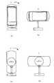
- FIG. 1 shows the terminal device 2 held by the terminal holding device 1.
- Fig.1 (a) has shown the front view
- FIG.1 (b) has shown the side view
- FIG.1 (c) has shown the rear view.
- the terminal holding device 1 mainly includes a base 11, a hinge 12, an arm 13, a substrate holder 15, and a terminal holder 16.
- the terminal holding device 1 functions as a so-called cradle, and a terminal device 2 such as a smartphone is attached.
- the base 11 functions as a base when the terminal holding device 1 is attached to a moving body such as a vehicle.
- a suction cup or an adhesive tape is provided on the lower surface of the base 11, and the base 11 is fixed to an installation surface 5 such as a dashboard of the vehicle by the adhesive tape.
- the hinge 12 is fixed to the arm 12 and is rotatably attached to the base 11. As the hinge 12 rotates, the arm 12 rotates in the front-rear direction of the terminal device 2, that is, in the directions of arrows 41 and 42 in FIG. That is, the installation angle of the substrate holder 15 and the terminal holder 16 with respect to the installation surface 5 can be adjusted by rotating the arm 12 via the hinge 12 with respect to the base 11 fixed to the installation surface 5 of the vehicle. .
- the terminal holder 16 is a holder that holds the terminal device 2.
- the terminal holder 16 includes a connector 16a and a wiring 16b.
- the connector 16 a is provided on the front surface of the terminal holder 16, that is, the bottom of the surface on which the terminal device 2 is installed, and is connected to the connector of the terminal device 2 when the terminal device 2 is installed on the terminal holder 16.
- the connector 16a is electrically connected to the sensor substrate 15c by the wiring 16b. Therefore, the detection signal from the sensor 15d is supplied to the terminal device 2 through the sensor substrate 15c, the wiring 16b, and the connector 16a.
- the terminal device 2 includes a front surface 2a having a display unit 25 such as a liquid crystal display panel on the front side of the terminal device 2 main body, and a back surface 2b on the back side of the terminal device 2 main body.
- a display unit 25 such as a liquid crystal display panel
- a back surface 2b on the back side of the terminal device 2 main body.
- the terminal device 2 is configured in a rectangular flat plate shape, and the front surface 2a and the back surface 2b are configured substantially in parallel.
- a camera 29 is provided on the back surface 2 b of the terminal device 2.
- a hole 17 is formed in the terminal holder 16 of the terminal holding device 1 at a position facing the camera 29 in a state where the terminal device 2 is held by the terminal holding device 1.
- the hole 17 is configured to have a diameter larger than the diameter of the lens of the camera 29.
- the camera 29 is provided on a substantially center line in the left-right direction of the back surface 2b of the terminal device 2, but the camera 29 is not limited to being provided at such a position.
- the camera 29 may be provided at a position somewhat away from the center line in the left-right direction of the back surface 2b.
- the terminal device 2 instead of forming the hole 17 in the terminal holder 16, the terminal device 2 is held by the terminal holding device 1, and the terminal device 2 is cut into a portion including the position where the camera 29 is provided. It is good also as forming a notch.
- the terminal holder 16 holding the terminal device 2 can be rotated by 90 degrees with respect to the substrate holder 15. That is, when the state of FIG. 1A is set to a rotation angle of 0 degrees, the terminal holder 16 is rotated in four angles of 0 degrees, 90 degrees, 180 degrees, and 270 degrees clockwise or counterclockwise. It is possible to fix.
- the reason why the rotation angle can be fixed every 90 degrees is that the user normally uses the display unit 25 in a vertically or horizontally arranged state when viewing the terminal device 2.
- the terminal device 2 usually has a rectangular flat plate shape, and “arranged vertically” means an arrangement in which the longitudinal direction of the display unit 25 is vertical.
- the “arrangement” is an arrangement in which the longitudinal direction of the display unit 25 is horizontal.
- FIG. 2 shows an example of a state in which the terminal holder 16 is rotated.
- the terminal holding device 1 is viewed from the front side, when the terminal holder 16 is rotated 90 degrees in the direction of the arrow from the state of FIG. 2A, the state shown in FIG.
- the terminal holding device 1 is viewed from the back side, when the terminal holder is rotated 90 degrees in the direction of the arrow from the state of FIG. 2C, the state shown in FIG.
- FIG. 3 schematically shows the configuration of the terminal device 2.
- the terminal device 2 mainly includes a CPU 21, a ROM 22, a RAM 23, a communication unit 24, a display unit 25, a speaker 26, a microphone 27, an operation unit 28, and a camera 29.
- the terminal device 2 is a portable terminal device having a call function such as a smartphone.
- the terminal device 2 is installed at a position on the dashboard where the driver of the vehicle can visually recognize the display unit 25 while being held by the terminal holding device 1.
- a CPU (Central Processing Unit) 21 controls the entire terminal device 2.
- a ROM (Read Only Memory) 22 has a nonvolatile memory (not shown) in which a control program for controlling the terminal device 2 is stored.
- a RAM (Random Access Memory) 23 stores data set by the user via the operation unit 26 so as to be readable, and provides a working area to the CPU 21.
- the communication unit 24 is configured to be able to perform wireless communication with other terminal devices 2 via a communication network.
- the display unit 25 is configured by a liquid crystal display, for example, and displays characters, images, and the like to the user.
- the speaker 26 outputs sound to the user.
- the microphone 27 collects sound emitted by the user.
- the operation unit 28 can be configured by an operation button or a touch panel type input device provided on the casing of the terminal device 2, and various selections and instructions by the user are input.
- the display unit 25 is a touch panel system
- the touch panel provided on the display screen of the display unit 25 also functions as the operation unit 28.
- the reason for adjusting the shooting direction will be briefly explained.
- AR navigation that performs route guidance using an image in front of the vehicle taken by the camera 29 of the terminal device 2 in a state where the terminal device 2 is installed in the vehicle via the terminal holding device 1.
- an image for route guidance such as a direction and a distance to a destination is superimposed on an image captured by the camera 29 and displayed. Therefore, when performing AR navigation, it can be said that it is desirable that the shooting direction of the camera 29 (specifically, the direction of the optical axis of the lens in the camera 29) matches the traveling direction of the vehicle.
- the user tends to install the terminal holding device 1 at an arbitrary position in the vehicle and install the terminal device 2 in an arbitrary direction.
- the “shooting direction” of the camera 29 means the direction in which the camera 29 faces, and more specifically corresponds to the direction of the optical axis of the lens of the camera 29.
- the “traveling direction” of the vehicle means the front-rear direction of the vehicle (specifically, the forward direction).
- the terminal device 2 is next attached to the terminal holding device 1.
- the adjustment image generated from the photographed image when the adjustment is performed is displayed superimposed on the current photographed image. Therefore, the user can easily adjust the shooting direction of the camera 29 to a desired direction by referring to the adjustment screen.
- FIG. 4 is a diagram illustrating an example of an adjustment image according to the first example.
- FIG. 4A shows an example of an image captured by the camera 29. This photographed image shows an example of an image in front of the vehicle photographed by the camera 29.
- the CPU 21 in the terminal device 2 generates an image as shown in FIG. 4B by performing binarization processing on the captured image as shown in FIG. And CPU21 produces
- an image or the like corresponding to the hood portion of the vehicle is mainly extracted, and an image in which other portions are erased is generated.
- the CPU 21 uses, as an adjustment image, an image obtained by translucent the image as shown in FIG.
- FIG. 6 is a diagram illustrating an example of an adjustment image and an adjustment screen according to the second example.
- FIG. 6A shows an example of a captured image similar to that shown in FIG.
- FIG. 6B shows an example of an adjustment image according to the second example.
- the CPU 21 in the terminal device 2 performs the image processing for extracting an image corresponding to a part of the vehicle from the captured image as shown in FIG. 6A, thereby adjusting as shown in FIG. An image is generated.
- This adjustment image is composed only of an image 60 showing the contour of the bonnet portion of the vehicle.
- the CPU 21 compares a plurality of captured images captured by the camera 29 and extracts a portion that has not changed in the plurality of captured images (in other words, by removing a portion that has changed). An adjustment image is generated.
- the user refers to such an adjustment screen to adjust the shooting direction of the camera 29 (in other words, adjust the orientation of the terminal device 2). Specifically, the user captures the camera 29 so that the position of the image corresponding to the bonnet portion in the actual captured image by the camera 29 matches the position corresponding to the bonnet portion indicated by the image 60 in the adjustment image. Adjust the direction.
- the first example described above can be applied.
- an image in which an image within a predetermined range located below the captured image is translucent can be generated as an adjustment image.
- step S105 the CPU 21 stores the captured image currently captured by the camera 29 in the ROM 22 or the like. In this case, the CPU 21 overwrites the previously stored captured image with the captured image captured this time. Then, the process proceeds to step S106.
- FIG. 8 is a flowchart showing the adjustment screen display process performed in step S102 described above. This processing is also realized by the CPU 21 in the terminal device 2 executing a program stored in the ROM 22 or the like.
- step S201 the CPU 21 determines whether or not an adjustment image exists. That is, the CPU 21 determines whether an adjustment image is stored in the ROM 22 or the like. If there is an adjustment image (step S201; Yes), the process proceeds to step S202. If there is no adjustment image (step S201; No), the process proceeds to step S205. In the latter case, since the adjustment image has not yet been generated, the adjustment screen is not displayed.
- step S204 the CPU 21 ends the display of the adjustment screen according to the instruction from the user. Then, the process proceeds to step S205.
- step S ⁇ b> 205 the CPU 21 displays an image captured by the camera 29 on the display unit 25. That is, the CPU 21 displays a captured image for AR navigation after this. Then, the process ends.
- steps S301 to S303 is the same as the processing of steps S101 to S103 shown in FIG. Here, the process after step S304 is demonstrated.
- whether or not to generate an adjustment image can be determined by the user's intention. Therefore, for example, in a situation where the user can determine that the terminal device 2 is not properly installed, it is possible to suppress storage of unnecessary captured images and generation of adjustment images. Further, according to the second embodiment, compared with the first embodiment, the processing load is not sequentially stored, so that the processing load can be reduced.
- the CPU 21 performs the first modification only when the point where the terminal device 2 is attached to the terminal holding device 1 coincides with the point where the terminal device 2 was previously removed from the terminal holding device 1. It is possible to display the adjustment image according to the above. This is because when the point where the terminal device 2 is attached coincides with the point where the terminal device 2 was previously removed (for example, when the terminal device 2 is attached or detached at the parking lot), When the terminal device 2 is removed and when the terminal device 2 is attached, the scenery in front of the vehicle has hardly changed, and the adjustment image according to the first modification as described above is used appropriately. This is because the shooting direction can be adjusted. Note that the CPU 21 determines whether or not the point where the terminal device 2 is removed matches the point where the terminal device 2 is attached based on, for example, a radio wave received by a GPS receiver in the terminal device 2. be able to.
- the CPU 21 In the second modification, the CPU 21 generates and stores adjustment images that differ depending on whether the terminal device 2 is arranged vertically or horizontally. Specifically, the CPU 21 determines whether the terminal device 2 is arranged vertically or horizontally, and an adjustment image generated when the terminal device 2 is arranged vertically (hereinafter, “ And the adjustment image generated when the terminal device 2 is arranged horizontally (hereinafter referred to as “second adjustment image”) separately from the ROM 22 or the like.
- second adjustment image an adjustment image generated when the terminal device 2 is arranged vertically
- second adjustment image an adjustment image generated when the terminal device 2 is arranged vertically
- the latest images are stored separately for both the first adjustment image and the second adjustment image.
- the CPU 21 determines whether the terminal device 2 is arranged vertically or horizontally, and the terminal device 2 is arranged vertically. In this case, the first adjustment image is read and displayed, and when the terminal device 2 is arranged horizontally, the second adjustment image is read and displayed. For example, the CPU 21 determines whether the terminal device 2 is arranged vertically or horizontally from the output of a sensor configured to detect the arrangement state of the terminal device 2 provided in the terminal device 2 or the terminal holding device 1. Determine if it is placed.
- an adjustment screen corresponding to each vehicle can be appropriately displayed.
Landscapes
- Engineering & Computer Science (AREA)
- Radar, Positioning & Navigation (AREA)
- Remote Sensing (AREA)
- Automation & Control Theory (AREA)
- General Physics & Mathematics (AREA)
- Multimedia (AREA)
- Physics & Mathematics (AREA)
- Signal Processing (AREA)
- Mechanical Engineering (AREA)
- Computer Vision & Pattern Recognition (AREA)
- Studio Devices (AREA)
- Navigation (AREA)
- Fittings On The Vehicle Exterior For Carrying Loads, And Devices For Holding Or Mounting Articles (AREA)
- Closed-Circuit Television Systems (AREA)
Abstract
Description
まず、本実施例に係る端末装置の構成について説明する。 [Device configuration]
First, the configuration of the terminal device according to the present embodiment will be described.
次に、本実施例に係る、カメラ29の撮影方向の調整方法について説明する。 [Adjusting the shooting direction]
Next, a method for adjusting the shooting direction of the
次に、上記した実施例に関する第1実施例について説明する。具体的には、図7及び図8を参照して、第1実施例において調整用画像の生成及び調整用画面の表示を行う際に実行される処理について説明する。 [Flow according to the first embodiment]
Next, a first embodiment relating to the above-described embodiment will be described. Specifically, with reference to FIG. 7 and FIG. 8, processing executed when generating an adjustment image and displaying an adjustment screen in the first embodiment will be described.
次に、第2実施例について説明する。具体的には、第2実施例において調整用画像の生成を行う際に実行される処理について説明する。 [Flow according to the second embodiment]
Next, a second embodiment will be described. Specifically, the process executed when the adjustment image is generated in the second embodiment will be described.
次に、変形例について説明する。 [Modification]
Next, a modified example will be described.
上記では、撮影画像の一部に対応する画像に基づいて調整用画像を生成する実施例を示したが、第1変形例では、撮影画像の概ね全体の画像に基づいて調整用画像を生成する。具体的には、第1変形例では、CPU21は、車両前方の風景を少なくとも含む画像に基づいて調整用画像を生成する。例えば、CPU21は、撮影画像の全体を半透明にすることで調整用画像を生成する。 (First modification)
In the above description, the adjustment image is generated based on an image corresponding to a part of the captured image. However, in the first modification, the adjustment image is generated based on almost the entire captured image. . Specifically, in the first modification, the CPU 21 generates an adjustment image based on an image including at least a landscape in front of the vehicle. For example, the CPU 21 generates an adjustment image by making the entire captured image semi-transparent.
第2変形例では、CPU21は、端末装置2が縦長に配置された場合と横長に配置された場合とで異なる調整用画像を生成して記憶させる。具体的には、CPU21は、端末装置2が縦長に配置されているか横長に配置されているかを判断し、端末装置2が縦長に配置されている場合に生成された調整用画像(以下、「第1調整用画像」と呼ぶ。)と、端末装置2が横長に配置されている場合に生成された調整用画像(以下、「第2調整用画像」と呼ぶ。)とを別個にROM22などに記憶させる。つまり、第1調整用画像及び第2調整用画像の両方について、最新の画像を別々に記憶させる。 (Second modification)
In the second modification, the CPU 21 generates and stores adjustment images that differ depending on whether the terminal device 2 is arranged vertically or horizontally. Specifically, the CPU 21 determines whether the terminal device 2 is arranged vertically or horizontally, and an adjustment image generated when the terminal device 2 is arranged vertically (hereinafter, “ And the adjustment image generated when the terminal device 2 is arranged horizontally (hereinafter referred to as “second adjustment image”) separately from the ROM 22 or the like. Remember me. That is, the latest images are stored separately for both the first adjustment image and the second adjustment image.
第3変形例では、CPU21は、調整用画像が生成された際に端末装置2が取り付けられていた車種ごとに、当該調整用画像を対応付けて記憶させる。つまり、CPU21は、ユーザが使用する複数の車両のそれぞれで生成された調整用画像を、当該複数の車両に対応付けて別々にROM22などに記憶させる。そして、CPU21は、当該複数の車両の中で端末装置2が現在取り付けられている車両に対応する調整用画像をROM22などから読み出して、読み出した調整用画像を表示させる。例えば、CPU21は、車両に設けられている診断用のポートなどを介して車種や車両情報などを取得することで、端末装置2が取り付けられている車両を特定する。 (Third Modification)
In the third modification, the CPU 21 stores the adjustment image in association with each vehicle type to which the terminal device 2 is attached when the adjustment image is generated. That is, the CPU 21 stores the adjustment images generated by each of the plurality of vehicles used by the user in the ROM 22 or the like separately in association with the plurality of vehicles. And CPU21 reads the image for adjustment corresponding to the vehicle to which the terminal device 2 is currently attached among the said some vehicles from ROM22 etc., and displays the read image for adjustment. For example, the CPU 21 specifies a vehicle to which the terminal device 2 is attached by acquiring a vehicle type, vehicle information, and the like via a diagnostic port provided in the vehicle.
上記では調整用画像を撮影画像に重畳して表示させる例を示したが、調整用画像と撮影画像とを相互に対比可能な態様であれば、このように重畳して表示させることに限定はされない。他の例では、調整用画像と撮影画像とを並べて表示させることができる。 (Other variations)
In the above, an example in which the adjustment image is displayed superimposed on the captured image is shown. However, if the adjustment image and the captured image can be compared with each other, there is no limitation on displaying the adjustment image in this manner. Not. In another example, the adjustment image and the captured image can be displayed side by side.
2 端末装置
15 基板ホルダ
16 端末ホルダ
21 CPU
25 表示部
28 操作部
29 カメラ 1 terminal holding device 2
25 Display unit 28
Claims (15)
- 移動体に取り付けられた保持装置に対して脱着可能な端末装置であって、
撮影手段と、
前記端末装置が前記保持装置に取り付けられた状態において前記撮影手段によって撮影された撮影画像を記憶する記憶手段と、
前記記憶手段に記憶された前記撮影画像に基づいて、前記撮影手段の撮影方向を調整するための調整用画像を生成する調整用画像生成手段と、
前記調整用画像生成手段によって生成された前記調整用画像を、前記撮影手段によって撮影された前記撮影画像と相互に対比可能な態様で表示する表示制御手段と、を備えることを特徴とする端末装置。 A terminal device detachable from a holding device attached to a moving body,
Photographing means;
Storage means for storing a photographed image photographed by the photographing means in a state where the terminal device is attached to the holding device;
Adjustment image generating means for generating an adjustment image for adjusting the shooting direction of the shooting means based on the shot image stored in the storage means;
And a display control unit that displays the adjustment image generated by the adjustment image generation unit in a manner comparable to the captured image captured by the imaging unit. . - 前記調整用画像生成手段は、前記記憶手段に記憶された前記撮影画像の少なくとも一部分の画像を半透明にした画像を、前記調整用画像として生成することを特徴とする請求項1に記載の端末装置。 2. The terminal according to claim 1, wherein the adjustment image generating unit generates, as the adjustment image, an image obtained by translucent at least a part of the captured image stored in the storage unit. apparatus.
- 前記調整用画像生成手段は、前記記憶手段に記憶された前記撮影画像の一部分の画像によって形成される画像を、前記調整用画像として生成することを特徴とする請求項1に記載の端末装置。 2. The terminal device according to claim 1, wherein the adjustment image generation unit generates an image formed by a partial image of the photographed image stored in the storage unit as the adjustment image.
- 前記撮影手段は、前記移動体の一部を含む範囲を撮影し、
前記調整用画像生成手段は、前記記憶手段に記憶された前記撮影画像の中の前記移動体の一部に対応する画像を抽出し、抽出した前記画像を前記一部分の画像として用いることを特徴とする請求項2又は3に記載の端末装置。 The photographing means photographs a range including a part of the moving body,
The adjustment image generating means extracts an image corresponding to a part of the moving body in the photographed image stored in the storage means, and uses the extracted image as the partial image. The terminal device according to claim 2 or 3. - 前記調整用画像生成手段は、前記記憶手段に記憶された前記撮影画像の下部に位置する所定範囲内の画像を、前記一部分の画像として用いることを特徴とする請求項2又は3に記載の端末装置。 4. The terminal according to claim 2, wherein the adjustment image generation unit uses an image within a predetermined range located below the captured image stored in the storage unit as the partial image. 5. apparatus.
- 前記調整用画像生成手段は、前記記憶手段に記憶された前記撮影画像において前記移動体の前方の風景を少なくとも含む画像に基づいて前記調整用画像を生成し、
前記表示制御手段は、前記端末装置が前記保持装置に取り付けられた地点が、前記端末装置が前記保持装置から取り外された地点に略一致する場合に、前記調整用画像を前記撮影画像と相互に対比可能な態様で表示することを特徴とする請求項1に記載の端末装置。 The adjustment image generation means generates the adjustment image based on an image including at least a landscape in front of the moving body in the captured image stored in the storage means,
When the point where the terminal device is attached to the holding device substantially coincides with the point where the terminal device is removed from the holding device, the display control means mutually displays the adjustment image with the captured image. The terminal device according to claim 1, wherein the terminal device is displayed in a comparable manner. - 前記表示制御手段は、前記端末装置が前記保持装置に取り付けられた際に、前記調整用画像を前記撮影画像と相互に対比可能な態様で表示することを特徴とする請求項1乃至6のいずれか一項に記載の端末装置。 7. The display control unit according to claim 1, wherein when the terminal device is attached to the holding device, the adjustment image is displayed in a manner that can be compared with the captured image. The terminal device according to claim 1.
- 前記撮影手段によって撮影された撮影画像を用いて経路案内を行う経路案内手段を更に備え、
前記記憶手段は、前記経路案内手段によって前記経路案内が行われている際に、前記撮影手段によって撮影された前記撮影画像を順次記憶することを特徴とする請求項1乃至7のいずれか一項に記載の端末装置。 Route guidance means for performing route guidance using a photographed image photographed by the photographing means;
8. The storage device according to claim 1, wherein the storage unit sequentially stores the photographed images photographed by the photographing unit when the route guidance is being performed by the route guidance unit. 9. The terminal device described in 1. - 前記調整用画像生成手段は、前記経路案内手段による前記経路案内が終了された際に、前記記憶手段に記憶された前記撮影画像に基づいて前記調整用画像を生成することを特徴とする請求項7に記載の端末装置。 The adjustment image generation unit generates the adjustment image based on the captured image stored in the storage unit when the route guidance by the route guidance unit is terminated. 8. The terminal device according to 7.
- 前記調整用画像生成手段は、前記端末装置が前記保持装置から取り外された際に、前記記憶手段に記憶された前記撮影画像に基づいて前記調整用画像を生成することを特徴とする請求項8又は9に記載の端末装置。 9. The adjustment image generation unit generates the adjustment image based on the captured image stored in the storage unit when the terminal device is detached from the holding device. Or the terminal device of 9.
- 前記撮影手段によって撮影された撮影画像を用いて経路案内を行う経路案内手段と、
前記調整用画像を生成するか否かの決定をユーザから取得する取得手段と、を更に備え、
前記取得手段は、前記経路案内手段による前記経路案内が終了された際に、前記調整用画像を生成するか否かの決定をユーザから取得し、
前記記憶手段は、前記取得手段がユーザから前記調整用画像を生成するとの決定を取得した場合に、前記撮影手段によって撮影された前記撮影画像を記憶し、
前記調整用画像生成手段は、前記取得手段がユーザから前記調整用画像を生成するとの決定を取得した場合に、前記記憶手段に記憶された前記撮影画像に基づいて前記調整用画像を生成することを特徴とする請求項1乃至7のいずれか一項に記載の端末装置。 Route guidance means for performing route guidance using a photographed image photographed by the photographing means;
An acquisition means for acquiring from the user a decision as to whether to generate the adjustment image;
The acquisition unit acquires a determination as to whether or not to generate the adjustment image from the user when the route guidance by the route guidance unit is terminated,
The storage means stores the photographed image photographed by the photographing means when the obtaining means obtains a decision to generate the adjustment image from a user,
The adjustment image generation unit generates the adjustment image based on the captured image stored in the storage unit when the acquisition unit acquires a decision to generate the adjustment image from a user. The terminal device according to claim 1, wherein: - 前記調整用画像生成手段は、前記調整用画像として、前記端末装置が縦長に配置された場合に前記調整に用いるための第1調整用画像と、前記端末装置が横長に配置された場合に前記調整に用いるための第2調整用画像とを生成し、
前記表示制御手段は、前記端末装置が縦長に配置された場合には、前記第1調整用画像を前記撮影画像と相互に対比可能な態様で表示し、前記端末装置が横長に配置された場合には、前記第2調整用画像を前記撮影画像と相互に対比可能な態様で表示することを特徴とする請求項1乃至11のいずれか一項に記載の端末装置。 The adjustment image generating means includes a first adjustment image for use in the adjustment when the terminal device is arranged vertically as the adjustment image, and a case where the terminal device is arranged horizontally. A second adjustment image for use in adjustment,
When the terminal device is arranged vertically, the display control means displays the first adjustment image in a manner comparable to the captured image, and the terminal device is arranged horizontally. The terminal device according to claim 1, wherein the second adjustment image is displayed in a manner that can be compared with the captured image. - 前記端末装置は、複数の移動体に前記保持装置を介して取り付けられ、
前記複数の移動体ごとに前記調整用画像生成手段によって生成された前記調整用画像を、前記複数の移動体に対応付けて記憶する調整用画像記憶手段を更に備え、
前記表示制御手段は、前記複数の移動体の中で前記端末装置が取り付けられている移動体に対応する前記調整用画像を前記調整用画像記憶手段から取得し、取得した前記調整用画像を前記撮影画像と相互に対比可能な態様で表示することを特徴とする請求項1乃至12のいずれか一項に記載の端末装置。 The terminal device is attached to a plurality of moving bodies via the holding device,
Adjustment image storage means for storing the adjustment image generated by the adjustment image generation means for each of the plurality of moving bodies in association with the plurality of moving bodies;
The display control means acquires the adjustment image corresponding to the moving body to which the terminal device is attached from the plurality of moving bodies from the adjustment image storage means, and acquires the acquired adjustment image. The terminal device according to any one of claims 1 to 12, wherein the terminal device is displayed in a manner that can be compared with a captured image. - 移動体に取り付けられた保持装置に対して脱着可能であり、撮影手段を有する端末装置によって実行される画像表示方法であって、
前記端末装置が前記保持装置に取り付けられた状態において前記撮影手段によって撮影された撮影画像を記憶する記憶工程と、
前記記憶工程によって記憶された前記撮影画像に基づいて、前記撮影手段の撮影方向を調整するための調整用画像を生成する調整用画像生成工程と、
前記調整用画像生成工程によって生成された前記調整用画像を、前記撮影手段によって撮影された前記撮影画像と相互に対比可能な態様で表示する表示制御工程と、を備えることを特徴とする画像表示方法。 An image display method that can be attached to and detached from a holding device attached to a moving body, and that is executed by a terminal device having a photographing unit,
A storage step of storing a photographed image photographed by the photographing means in a state where the terminal device is attached to the holding device;
An adjustment image generating step for generating an adjustment image for adjusting the shooting direction of the shooting means based on the shot image stored in the storage step;
A display control step of displaying the adjustment image generated by the adjustment image generation step in a manner that can be compared with the captured image captured by the imaging unit. Method. - 移動体に取り付けられた保持装置に対して脱着可能であり、撮影手段を有すると共にコンピュータを有する端末装置によって実行される画像表示プログラムであって、
前記コンピュータを、
前記端末装置が前記保持装置に取り付けられた状態において前記撮影手段によって撮影された撮影画像を記憶する記憶手段、
前記記憶手段によって記憶された前記撮影画像に基づいて、前記撮影手段の撮影方向を調整するための調整用画像を生成する調整用画像生成手段、
前記調整用画像生成手段によって生成された前記調整用画像を、前記撮影手段によって撮影された前記撮影画像と相互に対比可能な態様で表示する表示制御手段、として機能させることを特徴とする画像表示プログラム。 An image display program that can be attached to and detached from a holding device attached to a moving body, has a photographing unit, and is executed by a terminal device having a computer,
The computer,
Storage means for storing a photographed image photographed by the photographing means in a state where the terminal device is attached to the holding device;
Adjustment image generation means for generating an adjustment image for adjusting the shooting direction of the shooting means based on the shot image stored by the storage means;
An image display that functions as a display control unit that displays the adjustment image generated by the adjustment image generation unit in a manner that can be compared with the captured image captured by the imaging unit. program.
Priority Applications (3)
| Application Number | Priority Date | Filing Date | Title |
|---|---|---|---|
| PCT/JP2010/068711 WO2012053101A1 (en) | 2010-10-22 | 2010-10-22 | Terminal device, image display method executed by terminal device, and image display program |
| US13/880,870 US20130250141A1 (en) | 2010-10-22 | 2010-10-22 | Terminal device, image displaying method and image displaying program executed by terminal device |
| JP2011520474A JP4827994B1 (en) | 2010-10-22 | 2010-10-22 | Terminal device, image display method and image display program executed by terminal device |
Applications Claiming Priority (1)
| Application Number | Priority Date | Filing Date | Title |
|---|---|---|---|
| PCT/JP2010/068711 WO2012053101A1 (en) | 2010-10-22 | 2010-10-22 | Terminal device, image display method executed by terminal device, and image display program |
Publications (1)
| Publication Number | Publication Date |
|---|---|
| WO2012053101A1 true WO2012053101A1 (en) | 2012-04-26 |
Family
ID=45327155
Family Applications (1)
| Application Number | Title | Priority Date | Filing Date |
|---|---|---|---|
| PCT/JP2010/068711 WO2012053101A1 (en) | 2010-10-22 | 2010-10-22 | Terminal device, image display method executed by terminal device, and image display program |
Country Status (3)
| Country | Link |
|---|---|
| US (1) | US20130250141A1 (en) |
| JP (1) | JP4827994B1 (en) |
| WO (1) | WO2012053101A1 (en) |
Cited By (1)
| Publication number | Priority date | Publication date | Assignee | Title |
|---|---|---|---|---|
| JP2013231655A (en) * | 2012-04-27 | 2013-11-14 | Fujitsu Ten Ltd | Display system, portable device, on-vehicle unit, and program |
Families Citing this family (19)
| Publication number | Priority date | Publication date | Assignee | Title |
|---|---|---|---|---|
| US6360100B1 (en) | 1998-09-22 | 2002-03-19 | Qualcomm Incorporated | Method for robust handoff in wireless communication system |
| US9736752B2 (en) | 2005-12-22 | 2017-08-15 | Qualcomm Incorporated | Communications methods and apparatus using physical attachment point identifiers which support dual communications links |
| US8983468B2 (en) | 2005-12-22 | 2015-03-17 | Qualcomm Incorporated | Communications methods and apparatus using physical attachment point identifiers |
| US9066344B2 (en) | 2005-09-19 | 2015-06-23 | Qualcomm Incorporated | State synchronization of access routers |
| US8982778B2 (en) | 2005-09-19 | 2015-03-17 | Qualcomm Incorporated | Packet routing in a wireless communications environment |
| US8509799B2 (en) | 2005-09-19 | 2013-08-13 | Qualcomm Incorporated | Provision of QoS treatment based upon multiple requests |
| US9078084B2 (en) | 2005-12-22 | 2015-07-07 | Qualcomm Incorporated | Method and apparatus for end node assisted neighbor discovery |
| US9083355B2 (en) | 2006-02-24 | 2015-07-14 | Qualcomm Incorporated | Method and apparatus for end node assisted neighbor discovery |
| US9155008B2 (en) | 2007-03-26 | 2015-10-06 | Qualcomm Incorporated | Apparatus and method of performing a handoff in a communication network |
| US8830818B2 (en) | 2007-06-07 | 2014-09-09 | Qualcomm Incorporated | Forward handover under radio link failure |
| US9094173B2 (en) | 2007-06-25 | 2015-07-28 | Qualcomm Incorporated | Recovery from handoff error due to false detection of handoff completion signal at access terminal |
| US8615241B2 (en) | 2010-04-09 | 2013-12-24 | Qualcomm Incorporated | Methods and apparatus for facilitating robust forward handover in long term evolution (LTE) communication systems |
| JP6379376B2 (en) * | 2012-03-07 | 2018-08-29 | 本田技研工業株式会社 | Information display system for vehicles |
| JP5899021B2 (en) * | 2012-03-28 | 2016-04-06 | 本田技研工業株式会社 | Method for discriminating mounting position of portable information terminal to vehicle |
| JP6025365B2 (en) * | 2012-04-04 | 2016-11-16 | 京セラ株式会社 | Calibration processing apparatus, camera calibration apparatus, camera system, and camera calibration method |
| FR3035042B1 (en) * | 2015-04-17 | 2017-05-19 | Faurecia Interieur Ind | ASSEMBLY COMPRISING A PORTABLE ELECTRONIC APPARATUS AND A HOLDER FOR FIXING THE PORTABLE ELECTRONIC DEVICE |
| TWI598723B (en) * | 2016-05-24 | 2017-09-11 | 鴻海精密工業股份有限公司 | Camera fixing device |
| US9961306B1 (en) * | 2017-05-22 | 2018-05-01 | Yaron LEV | Smart holder |
| CN110395189B (en) * | 2018-04-24 | 2022-12-09 | 比亚迪股份有限公司 | Actuating mechanism for adjusting vehicle-mounted display terminal and vehicle |
Citations (3)
| Publication number | Priority date | Publication date | Assignee | Title |
|---|---|---|---|---|
| JP2008542746A (en) * | 2005-06-06 | 2008-11-27 | トムトム インターナショナル ベスローテン フエンノートシャップ | Navigation device with camera information |
| JP2010163114A (en) * | 2009-01-19 | 2010-07-29 | Hitachi Ltd | Portable navigation device with camera |
| JP2010210257A (en) * | 2009-03-06 | 2010-09-24 | Sony Corp | Navigation device and navigation method |
Family Cites Families (3)
| Publication number | Priority date | Publication date | Assignee | Title |
|---|---|---|---|---|
| JP4045862B2 (en) * | 2002-06-03 | 2008-02-13 | 日産自動車株式会社 | Optical axis deviation detection device for in-vehicle camera |
| JP2004352065A (en) * | 2003-05-28 | 2004-12-16 | Toyota Motor Corp | Parking assistance device |
| US7839431B2 (en) * | 2006-10-19 | 2010-11-23 | Robert Bosch Gmbh | Image processing system and method for improving repeatability |
-
2010
- 2010-10-22 JP JP2011520474A patent/JP4827994B1/en not_active Expired - Fee Related
- 2010-10-22 US US13/880,870 patent/US20130250141A1/en not_active Abandoned
- 2010-10-22 WO PCT/JP2010/068711 patent/WO2012053101A1/en active Application Filing
Patent Citations (3)
| Publication number | Priority date | Publication date | Assignee | Title |
|---|---|---|---|---|
| JP2008542746A (en) * | 2005-06-06 | 2008-11-27 | トムトム インターナショナル ベスローテン フエンノートシャップ | Navigation device with camera information |
| JP2010163114A (en) * | 2009-01-19 | 2010-07-29 | Hitachi Ltd | Portable navigation device with camera |
| JP2010210257A (en) * | 2009-03-06 | 2010-09-24 | Sony Corp | Navigation device and navigation method |
Cited By (1)
| Publication number | Priority date | Publication date | Assignee | Title |
|---|---|---|---|---|
| JP2013231655A (en) * | 2012-04-27 | 2013-11-14 | Fujitsu Ten Ltd | Display system, portable device, on-vehicle unit, and program |
Also Published As
| Publication number | Publication date |
|---|---|
| JP4827994B1 (en) | 2011-11-30 |
| US20130250141A1 (en) | 2013-09-26 |
| JPWO2012053101A1 (en) | 2014-02-24 |
Similar Documents
| Publication | Publication Date | Title |
|---|---|---|
| JP4827994B1 (en) | Terminal device, image display method and image display program executed by terminal device | |
| JP5341789B2 (en) | Parameter acquisition apparatus, parameter acquisition system, parameter acquisition method, and program | |
| JP6077214B2 (en) | Image processing apparatus, image processing method, program, and image processing system | |
| WO2012035886A1 (en) | Terminal holding device | |
| JP4801232B1 (en) | Terminal device, image display method and image display program executed by terminal device | |
| JP5047650B2 (en) | In-vehicle camera system | |
| JP2009043003A (en) | Driving support apparatus | |
| JP2022070939A (en) | Imaging apparatus, control method, program, and storage medium | |
| JP2016192772A (en) | Display device and program | |
| JP2013055416A (en) | Exterior video provision system | |
| JP2012095283A (en) | Terminal device, image display method and image display program executed by terminal device | |
| JP5571720B2 (en) | Navigation system, navigation method, navigation program, and terminal device | |
| JP4579132B2 (en) | Vehicle / Ambient Image Providing Device | |
| JP4325410B2 (en) | In-vehicle device | |
| JP5174942B2 (en) | Terminal device, image display method and image display program executed by terminal device | |
| WO2012053102A1 (en) | Terminal device, image processing method and image processing program executed by terminal device | |
| JP5036895B2 (en) | Terminal device, image display method and image display program executed by terminal device | |
| JP6148896B2 (en) | Image generating apparatus and image generating method | |
| JP4982255B2 (en) | In-vehicle display device | |
| JP2012230115A (en) | Terminal device, and image display method and image display program executed by terminal device | |
| JP2016141303A (en) | Visual field support device | |
| JP5204926B2 (en) | Terminal holding device | |
| JP6866765B2 (en) | Bird's-eye view image generation device, bird's-eye view image generation system, bird's-eye view image generation method and program | |
| JP2023094982A (en) | Communication system, information processing device, information processing method, program, and recording medium | |
| JP2014137761A (en) | Drive assist device and drive assist method |
Legal Events
| Date | Code | Title | Description |
|---|---|---|---|
| WWE | Wipo information: entry into national phase |
Ref document number: 2011520474 Country of ref document: JP |
|
| 121 | Ep: the epo has been informed by wipo that ep was designated in this application |
Ref document number: 10858655 Country of ref document: EP Kind code of ref document: A1 |
|
| NENP | Non-entry into the national phase |
Ref country code: DE |
|
| WWE | Wipo information: entry into national phase |
Ref document number: 13880870 Country of ref document: US |
|
| 122 | Ep: pct application non-entry in european phase |
Ref document number: 10858655 Country of ref document: EP Kind code of ref document: A1 |