WO2012030882A1 - Valve guard - Google Patents
Valve guard Download PDFInfo
- Publication number
- WO2012030882A1 WO2012030882A1 PCT/US2011/049826 US2011049826W WO2012030882A1 WO 2012030882 A1 WO2012030882 A1 WO 2012030882A1 US 2011049826 W US2011049826 W US 2011049826W WO 2012030882 A1 WO2012030882 A1 WO 2012030882A1
- Authority
- WO
- WIPO (PCT)
- Prior art keywords
- valve
- section
- valve guard
- eccentric base
- gas cylinder
- Prior art date
- Legal status (The legal status is an assumption and is not a legal conclusion. Google has not performed a legal analysis and makes no representation as to the accuracy of the status listed.)
- Ceased
Links
Classifications
-
- F—MECHANICAL ENGINEERING; LIGHTING; HEATING; WEAPONS; BLASTING
- F17—STORING OR DISTRIBUTING GASES OR LIQUIDS
- F17C—VESSELS FOR CONTAINING OR STORING COMPRESSED, LIQUEFIED OR SOLIDIFIED GASES; FIXED-CAPACITY GAS-HOLDERS; FILLING VESSELS WITH, OR DISCHARGING FROM VESSELS, COMPRESSED, LIQUEFIED, OR SOLIDIFIED GASES
- F17C13/00—Details of vessels or of the filling or discharging of vessels
- F17C13/04—Arrangement or mounting of valves
-
- F—MECHANICAL ENGINEERING; LIGHTING; HEATING; WEAPONS; BLASTING
- F16—ENGINEERING ELEMENTS AND UNITS; GENERAL MEASURES FOR PRODUCING AND MAINTAINING EFFECTIVE FUNCTIONING OF MACHINES OR INSTALLATIONS; THERMAL INSULATION IN GENERAL
- F16K—VALVES; TAPS; COCKS; ACTUATING-FLOATS; DEVICES FOR VENTING OR AERATING
- F16K1/00—Lift valves or globe valves, i.e. cut-off apparatus with closure members having at least a component of their opening and closing motion perpendicular to the closing faces
- F16K1/30—Lift valves or globe valves, i.e. cut-off apparatus with closure members having at least a component of their opening and closing motion perpendicular to the closing faces specially adapted for pressure containers
- F16K1/307—Additional means used in combination with the main valve
-
- F—MECHANICAL ENGINEERING; LIGHTING; HEATING; WEAPONS; BLASTING
- F16—ENGINEERING ELEMENTS AND UNITS; GENERAL MEASURES FOR PRODUCING AND MAINTAINING EFFECTIVE FUNCTIONING OF MACHINES OR INSTALLATIONS; THERMAL INSULATION IN GENERAL
- F16K—VALVES; TAPS; COCKS; ACTUATING-FLOATS; DEVICES FOR VENTING OR AERATING
- F16K27/00—Construction of housing; Use of materials therefor
- F16K27/12—Covers for housings
-
- F—MECHANICAL ENGINEERING; LIGHTING; HEATING; WEAPONS; BLASTING
- F17—STORING OR DISTRIBUTING GASES OR LIQUIDS
- F17C—VESSELS FOR CONTAINING OR STORING COMPRESSED, LIQUEFIED OR SOLIDIFIED GASES; FIXED-CAPACITY GAS-HOLDERS; FILLING VESSELS WITH, OR DISCHARGING FROM VESSELS, COMPRESSED, LIQUEFIED, OR SOLIDIFIED GASES
- F17C2201/00—Vessel construction, in particular geometry, arrangement or size
- F17C2201/01—Shape
- F17C2201/0104—Shape cylindrical
-
- F—MECHANICAL ENGINEERING; LIGHTING; HEATING; WEAPONS; BLASTING
- F17—STORING OR DISTRIBUTING GASES OR LIQUIDS
- F17C—VESSELS FOR CONTAINING OR STORING COMPRESSED, LIQUEFIED OR SOLIDIFIED GASES; FIXED-CAPACITY GAS-HOLDERS; FILLING VESSELS WITH, OR DISCHARGING FROM VESSELS, COMPRESSED, LIQUEFIED, OR SOLIDIFIED GASES
- F17C2201/00—Vessel construction, in particular geometry, arrangement or size
- F17C2201/05—Size
- F17C2201/056—Small (<1 m3)
-
- F—MECHANICAL ENGINEERING; LIGHTING; HEATING; WEAPONS; BLASTING
- F17—STORING OR DISTRIBUTING GASES OR LIQUIDS
- F17C—VESSELS FOR CONTAINING OR STORING COMPRESSED, LIQUEFIED OR SOLIDIFIED GASES; FIXED-CAPACITY GAS-HOLDERS; FILLING VESSELS WITH, OR DISCHARGING FROM VESSELS, COMPRESSED, LIQUEFIED, OR SOLIDIFIED GASES
- F17C2201/00—Vessel construction, in particular geometry, arrangement or size
- F17C2201/05—Size
- F17C2201/058—Size portable (<30 l)
-
- F—MECHANICAL ENGINEERING; LIGHTING; HEATING; WEAPONS; BLASTING
- F17—STORING OR DISTRIBUTING GASES OR LIQUIDS
- F17C—VESSELS FOR CONTAINING OR STORING COMPRESSED, LIQUEFIED OR SOLIDIFIED GASES; FIXED-CAPACITY GAS-HOLDERS; FILLING VESSELS WITH, OR DISCHARGING FROM VESSELS, COMPRESSED, LIQUEFIED, OR SOLIDIFIED GASES
- F17C2205/00—Vessel construction, in particular mounting arrangements, attachments or identifications means
- F17C2205/01—Mounting arrangements
- F17C2205/0153—Details of mounting arrangements
- F17C2205/0157—Details of mounting arrangements for transport
- F17C2205/0165—Details of mounting arrangements for transport with handgrip
-
- F—MECHANICAL ENGINEERING; LIGHTING; HEATING; WEAPONS; BLASTING
- F17—STORING OR DISTRIBUTING GASES OR LIQUIDS
- F17C—VESSELS FOR CONTAINING OR STORING COMPRESSED, LIQUEFIED OR SOLIDIFIED GASES; FIXED-CAPACITY GAS-HOLDERS; FILLING VESSELS WITH, OR DISCHARGING FROM VESSELS, COMPRESSED, LIQUEFIED, OR SOLIDIFIED GASES
- F17C2205/00—Vessel construction, in particular mounting arrangements, attachments or identifications means
- F17C2205/03—Fluid connections, filters, valves, closure means or other attachments
- F17C2205/0302—Fittings, valves, filters, or components in connection with the gas storage device
- F17C2205/0308—Protective caps
-
- F—MECHANICAL ENGINEERING; LIGHTING; HEATING; WEAPONS; BLASTING
- F17—STORING OR DISTRIBUTING GASES OR LIQUIDS
- F17C—VESSELS FOR CONTAINING OR STORING COMPRESSED, LIQUEFIED OR SOLIDIFIED GASES; FIXED-CAPACITY GAS-HOLDERS; FILLING VESSELS WITH, OR DISCHARGING FROM VESSELS, COMPRESSED, LIQUEFIED, OR SOLIDIFIED GASES
- F17C2205/00—Vessel construction, in particular mounting arrangements, attachments or identifications means
- F17C2205/05—Vessel or content identifications, e.g. labels
- F17C2205/057—Vessel or content identifications, e.g. labels by chips
-
- F—MECHANICAL ENGINEERING; LIGHTING; HEATING; WEAPONS; BLASTING
- F17—STORING OR DISTRIBUTING GASES OR LIQUIDS
- F17C—VESSELS FOR CONTAINING OR STORING COMPRESSED, LIQUEFIED OR SOLIDIFIED GASES; FIXED-CAPACITY GAS-HOLDERS; FILLING VESSELS WITH, OR DISCHARGING FROM VESSELS, COMPRESSED, LIQUEFIED, OR SOLIDIFIED GASES
- F17C2205/00—Vessel construction, in particular mounting arrangements, attachments or identifications means
- F17C2205/05—Vessel or content identifications, e.g. labels
- F17C2205/058—Vessel or content identifications, e.g. labels by Radio Frequency Identification
-
- F—MECHANICAL ENGINEERING; LIGHTING; HEATING; WEAPONS; BLASTING
- F17—STORING OR DISTRIBUTING GASES OR LIQUIDS
- F17C—VESSELS FOR CONTAINING OR STORING COMPRESSED, LIQUEFIED OR SOLIDIFIED GASES; FIXED-CAPACITY GAS-HOLDERS; FILLING VESSELS WITH, OR DISCHARGING FROM VESSELS, COMPRESSED, LIQUEFIED, OR SOLIDIFIED GASES
- F17C2260/00—Purposes of gas storage and gas handling
- F17C2260/01—Improving mechanical properties or manufacturing
- F17C2260/011—Improving strength
Definitions
- the present invention is directed and relates to the field of gas delivery systems and gas cylinders used in such systems. More specifically embodiments of the present invention are directed to protective valve guards and caps designed to protect gas cylinders and gas cylinder valves.
- Pressurized gas tanks, or cylinders are used to contain, store, release and transport gases where needed. During transit, operation or storage, etc. such cylinders are often at risk of tipping or falling, etc. For example, upon their being emptied, such cylinders are often returned or moved to a plant or larger gas storage or gas delivery facility for refilling.
- valve caps also known as valve guards
- Many types of protective valve guards or caps are known. Many guards are easily removable, while others are held fixedly in position to the tank at, or just beyond, the neck area. In many instances, the guards are inverted cup like objects that completely or partially encase the cylinder valve. In some instances, the guard is threaded at its open end and designed to engage threads manufactured into the cylinder at a location at or near the cylinder neck.
- Such known caps still present disadvantages. For example, impact on the caps may protect gas discharge, however, the threads connecting the cap/guard to the cylinder are also prone to damage, requiring the tank to be taken out of service.
- valve guard assemblies have not solved the problem of providing an easily manufactured, durable valve guard that would be uniform in its use with the varying cylinder neck diameters that exist. Further, in an attempt to preserve the thread integrity at cylinder necks while attempting to fixedly attach valve guards to cylinder necks, known valve guard assemblies present multiple parts, leading to the need to inventory various parts, etc.
- Embodiments of the present invention overcome the foregoing and other drawbacks of the prior art by providing a valve guard for a gas cylinder comprising a main body section and an eccentric base section in communication with the main body section.
- the eccentric base section is integral with the main body section and is adapted to engage a neck section of the gas cylinder, while being ergonomically advantageous in design.
- gas cylinders are fitted with a unitary valve guard dimensioned to at least partially enclose a valve section extending from the neck section of the gas cylinder while simultaneously providing access to a valve.
- a unitary valve guard dimensioned to at least partially enclose a valve section extending from the neck section of the gas cylinder while simultaneously providing access to a valve.
- at least one opening ergonomically provides access for a means for lifting and/or moving the gas cylinder.
- the present invention is directed to gas delivery systems having gas cylinders fitted with a unitary valve guard comprising a valve guard main body section comprising at least one access opening and dimensioned to partially encase the valve section.
- the unitary valve guard further comprises an integral eccentric base section comprising an inner wall having threads to mate with the threads on the gas cylinder.
- the integral eccentric base further comprises an outer wall, with the base having a variable thickness occurring between the inner and outer walls about the circumference of the base.
- the eccentric base is discontinuous, having an open section gap found at one or more locations about its
- the eccentric base has a first end and a second end creating a gap there between.
- the first and second ends of the eccentric base (created by the presence of the gap) preferably have corresponding first and second recessed sections located on the outer surface of the eccentric base adjacent the first and second ends.
- the first and second ends each comprise a first and second end thickness extending between the inner and outer surfaces of the eccentric base at the open section gap.
- the first and second ends each have bore holes extending from the end surface into the base and extending through and into the first and second recessed sections.
- the first and second bore holes are preferably positioned relative to one another in a configuration to receive a fastener.
- the fastener preferably comprises a substantially linear component that extends from the first recessed section and into and out of the first bore hole and proceeds at least into the second borehole and, in other
- the fastener is then able to be adjusted, if necessary, to tighten the eccentric base, thereby fixedly, and preferably removably attaching the base to the neck of the gas cylinder.
- FIGs. 1A and IB are perspective drawings of the eccentric base of the present invention.
- FIGs. 2 and 3 show perspective views of an embodiment of the valve guard with an integral eccentric base section in position atop a gas cylinder.
- FIGs. 4A and 4B show a gas cylinder having threads in the neck section without a valve guard in place.
- FIGs. 5A and 5B show a perspective" front" view and full “front” view respectively of the valve guard with discontinuous integral eccentric base and access opening for a valve in position atop the gas cylinder.
- FIG. 6 is a side view of the valve guard shown in FIG. 5A and 5B.
- FIGs. 7 and 8 show a full front and perspective front view (in close-up) respectively of embodiments of the valve guard of the present invention.
- FIGs. 9 and 10 are close-up views of the recessed sections and the gap section on the discontinuous integral base section of the valve guard.
- FIGs. 11 and 12 show the preferred ergonomic features of the valve guard.
- FIG. 13 is a perspective overhead view of the valve guard showing a tracking and monitoring feature.
- FIG. 14 is a schematic of a continuous eccentric base of the present invention without a gap section.
- FIGs. 15A-15C are graphs showing the material deformation calculation of simulated impact testing.
- FIGs. 16A-16C are graphs showing the mechanical stress calculation results of simulated impact testing.
- FIGs. 17A-17B show front and underside views, respectively, of the valve guard of the present invention showing one preferred placement of a tracking and monitoring device.
- FIGs. 1A and IB shows the base section of a preferred embodiment of the present invention.
- Integral discontinuous eccentric base section 10 has an inner wall 12 and outer wall 14.
- Inner wall 12 comprises threads 16 for engaging, for example, the threads found on a neck section of a gas cylinder (not shown).
- a specified wall thickness is formed over the distance between the inner wall 12 and outer wall 14.
- the wall thickness is intentionally variable about the circumference of the discontinuous eccentric base element 10, such that, the wall thickness is preferably greatest, for example, preferably about 24 mm at the first 18 and second 20 ends compared to preferably about 13 mm wall thickness diagonally opposite to ends 18, 20, and preferably about 14 mm wall thickness along the line bisecting the diagonal at 90 degrees.
- the eccentric base element is discontinuous, creating ends 18, 20. Such ends 18, 20 abut and are proximate to a gap 24.
- FIG. 1A further shows first and second recessed areas 26, 28 cut, forged, otherwise machined, etc. into the outer surface 30 of eccentric base section 10.
- First end 18 has a first bore 32 that extends from the first end into and through the eccentric base 10 and into the first recessed area, or section 26.
- second end 20 has a second bore 34 that extends from the second end into and through the eccentric base 10 and into the second recessed area, or section 28.
- FIGs. 2 and 3 show a full “rear” and perspective “rear” view
- valve guard 40 attached to gas cylinder 44.
- the integral discontinuous eccentric base section 10 is shown in intimate contact with the outer surface of the collar neck section 42 of gas cylinder 44. As shown in FIG. 1, the internal threads found on the inner surface of eccentric base section 10 engage threads (not shown) on collar neck section 42 of gas cylinder 44.
- Valve 46 with valve hand wheel 54 is shown in intimate contact with, and extending upwardly from, collar neck section 42.
- Valve guard 40 is cut, forged, molded, otherwise machined, etc. to form openings 48, 50 on the one side of the valve guard 40.
- Rib 52 is located and formed via the cutting, forging, molding, machining, etc. of openings 48, 50, and is preferably positioned at approximately the height of a valve hand wheel 54.
- valve guard 40 protects valve 46 from damage if the cylinder is upset, dropped, etc.
- rib 52 allows valve guard 40 to have a support that may engage an automatic or manual lifting mechanism (not shown).
- Valve guard 40 additionally may support a lifting mechanism through opening 48 as the lifting mechanism engages, not rib 52, but the top 56 of the valve guard 40.
- the position and dimension of opening 50 is oriented and dimensioned to facilitate the visual inspection of cylinder features including, for example, the pressure relief device (PRD) 49 FIGs. 2 and 3 and valve threads 61, the introduction of leak integrity medias (for example, liquids, or electronic leak detectors, etc.), and for verifying the identification of, for example, material compatibility with the gas service content of the PRD 49 etc. Opening 50 further significantly minimizes time inspection as compared to known removable caps or cylinder guards.
- PRD pressure relief device
- FIGs. 4A and 4B show views of the upper region of gas cylinder 44 with collar neck section 42 from which valve 46 extends vertically upward, and valve guard removed.
- Valve 46 has two outlets 47, 49.
- Collar neck section threads 58 on gas cylinder 44 are shown, into which the threads on the inner surface of the eccentric base section 10 of the valve are intertwined when the valve guard is screwed into position.
- FIGS. 5A and 5B show valve guard 40 mounted in intimate contact with gas cylinder 44.
- valve 46 is still fully visible and accessible to a predetermined degree via opening 48 and fully accessible via opening 58 in valve guard 40.
- the integral discontinuous eccentric base section 10 of valve guard 40 shows recessed areas 26, 28, and gap 24 located therebetween. Close-up views are shown in FIGs 9 and 10.
- valve guard 40 The side view of valve guard 40 shown in FIG. 6 makes clear that the valve 46 and valve hand wheel 54 (neither of which are shown) in FIG. 6 are completely protected by valve guard 40 in the event that gas cylinder 44 becomes upset, is dropped, falls, or otherwise moves from its safe upright position, and, instead is moved to a position where the ground or another object may strike the vulnerable valve 46 and/or valve hand wheel 54.
- FIGs. 7 and 8 show an accessory 60 being attached to valve 46 and extending through opening 58 of valve guard 40.
- FIG. 7 further illustrates how the valve 46 may be repaired or augmented without removing the valve guard, resulting in greater ease, safety and cost-reduction, as such operation requires less time.
- tool 62 is shown engaging nut 64 of accessory 60.
- the shown accessory 60 is preferably a regulator such as, for example, a fast connector, etc.
- Embodiments of the present invention provide for significantly greater ease of access to valve 46 and other cylinder connection devices via opening 58, as compared with known valve protectors.
- embodiments of the present invention contemplate dimensioning a valve cover and orienting and positioning openings in the valve cover that facilitate access, such as, for example, with tools to service, maintain, repair, adjust, inspect, etc. the valve region of the cylinder; or scanning devices or manual vision, to read information present on or near the valve region of the cylinder, etc.
- FIGs. 9 and 10 show, in close-up view, the recessed areas 26, 28 on the integral eccentric base section 10 of the valve guard 40.
- Fastener 31 is shown extending from the second recessed section 28 past gap 24 and into first recessed section 26, through first and second recessed bores (not shown).
- the fastener comprises a substantially non-linear component, and irrespective of whether linear or non-linear, the component need not extend all the way into the second recessed section.
- one or more of fasteners, bore holes and associated recessed sections described above are not required to fixedly and removably attach the eccentric base to the neck of the gas cylinder.
- FIGs. 11 and 12 show the ease with which embodiments of the present invention may be manipulated and the ergonomic advantages of the valve cover 40.
- a gas cylinder equipped with the valve guard of the present invention may be moved from its upright position of rest and moved.
- the gas cylinder 44 may be easily, securely and safely gripped at the valve cover 40, via openings in the valve cover. All manipulation and resulting movement of the gas cylinder 44, occurs with energy and force directed only to the valve cover without any danger or risk of placing any force on the valve itself; a common problem when conventionally moving cylinders, as workers may improperly grasp heavy cylinders by the valve, risking damage to the valve, the cylinder, etc., as well as creating safety hazards.
- the preselected dimensions of the upper region of the valve cover 40 allows a manual operator to move the cylinder while engaging the cylinder only at the upper, preferably "domed" region of the valve cover 40.
- the preselected design of the valve cover 40 serves to minimize the potentially damaging physical effects that often occur as the weight of the cylinder, and the energy required for moving cylinders often causes damage to an operator as well as the cylinder.
- the valve covers of the present invention offer ergonomic advantages (as compared with known valve covers) serving to significantly reduce the occurrence of injuries to an operator, such as, for example, wrist strain and stress, etc., as well as more severe injury.
- valve cover dimensioned and oriented to improve safety to the cylinder as well as the operator, as the valve cover is significantly more easily gripped. This reduces the chances of losing control of, and damaging a cylinder. Such cylinder damage could then result in an uncontrolled release of cylinder contents, and potential cause the cylinder to launch unpredictably at high velocity, potentially causing significant injury, fatality and/or property damage. Cylinder content release could also result in a significant environmental hazard, such as, for example, asphyxiation,
- FIG. 13 shows a cavity 70 in the upper region 56 of valve cover 40, into which a tracking device 72 may be placed to encode information relating to the location, movement, storage, contents, age, source of origin, etc. of the gas cylinder to which the valve cover is attached, such as, for example, an
- electromagnetic coupled information storage device etc.
- eccentric base section While only embodiments of the discontinuous eccentric base section are shown in the FIGs., it is understood that embodiments of the present invention include an eccentric base section that is not discontinuous. In such embodiments, it is contemplated that the fastener element may not be necessary, nor would the eccentric base design require recessed sections that had been bored through at their ends (since there would be no "ends" present).
- One important aspect of the eccentric base section of the valve guard is the significantly added strength and integrity that such a structural object has over known valve guards. Indeed, the term “eccentric” refers to an elliptical shape (a shape having more than one foci, or non-circular).
- the eccentric base section of the valve guard has a substantially circular inner wall that is preferably threaded.
- the outer wall is eccentric, or elliptical, thereby making the entire inside surface of the base substantially circular (to better fit the substantially circular neck section of a gas cylinder), but also outwardly eccentric according to the eccentric base's outer circumference.
- the wall thickness of the base about its circumference must vary at one or more locations.
- the wall thickness of the base is at its thickest at the two "ends". This added thickness at the location on the base at which a fastener is used to further secure the valve guard to the gas cylinder imparts significantly increased structural integrity and durability of the guard and the now-guarded cylinder.
- the 14 shows a modeled eccentric base with X, Y and Z axes.
- the Z axis runs from the "front" of the eccentric base to the "back", while the X axis represents the direction from the sides of the eccentric base, bisecting the Z axis at 90 degrees.
- the Y axis represents the vertical direction of a standing cylinder, with valve guard in place. Stress and deformation calculations were made by evenly dividing eccentric base thickness (the distance between the inner and outer walls at the front and back of the eccentric base) into three “zones" along the Z axis. As shown in FIG. 14, Zones 1, 2, and 3 are in the front, and Zones 4, 5 and 6 in the back.
- Zones 1 and 4 were defined as Rear (R) region, or the Zones closest to the inner circumference of the eccentric base.
- Zones 2 and 5 were defined as Mid (M) region and Zones 3 and 6 were defined as Front (F) region to study the effect on structural integrity in each region as a function of base eccentricity.
- Material deformation and mechanical stress calculations were performed for three thickness values of the eccentric base front and back, tl, t2 and t3, where t3>t2>tl and the difference between t2 and tl equals "a"; the difference between t3 and tl equals "b".
- FIGs 15A-C are illustrative plots of averages of deformation along X, Y, and Z-axes as a function of the difference in thickness of front and back sections.
- Tables 15a-c show the material deformation results
- FIGs 15A-C are illustrative plots of these averages from Tables 15a-c along X, Y, and Z-axes as a function of the difference in thickness of front and back sections.
- Zero (“0") in Tables 15a-c and FIGs 15A-C refers to the baseline where the thickness of the front and back are equal, or the base is concentric (not eccentric). As a result the deformation is set to be 100%.
- the difference is "-a" or "-b".
- Tables 16a-c show the results of the mechanical stress test runs.
- FIGs 16A-C are illustrative plots of averages from Tables 16a-c of stresses along X, Y and Z-axes as a function of the differences in the thickness of front and back sections.
- valve guards that are secured via threads and fasteners to present a largely immovable valve guard
- embodiments of the present invention are contemplated whereby the valve guard is removable after attachment to the neck of the gas cylinder. It is the present industry standard for gas cylinders to be manufactured with threads on a neck.
- the scope of the present invention further contemplates adaptations whereby the base of the valve guard may be dimensioned to mate with threads found, for example, beyond the neck of the gas cylinder, or mated via a mating arrangement that does not require threads, etc.
- valve guards of the present invention are preferably made from materials that may be cast or molded and that conform to industry health and safety standards.
- An example of such a material is Nodular Iron.
- Durable ceramics, plastics, composite materials, etc. may be used alone or in combination, in one or more layers, or as a laminate, etc.
- At least one opening is present for access to the gas cylinder valve.
- the gas valve in preferred embodiments, is effectively encased within the valve guard such that the dimensions of the valve guard would cause the guard to strike or be struck by another object or surface, and inhibit such object, or surface from striking the valve.
- such an effect is achieved by the valve guards of the present invention.
- the valve guards of the present invention via an access opening, substantially simultaneously allow for the servicing, inspection, and/or augmentation of the valve assembly, as well as cylinder identification, etc., without removing the valve guard.
- the present invention contemplates conserving material for the valve guard by machining at least one opening in the valve guard, preferably on the side of the valve guard opposing the main access opening for the valve maintenance.
- a horizontal "rib" or cross-strut is formed.
- This rib is ideally positioned, according to preferred embodiments, at a height approximately equal to the height of the valve hand wheel to help guard against the valve hand wheel being struck by, or striking another object.
- the rib may be used as a surface for a lifting or moving means, for the purpose of automatically or manually moving or lifting the cylinder.
- the top of the valve guard also may be engaged by a lifting means through one or both of the openings for the purpose of automatically or manually moving, maneuvering, lifting, etc. the cylinder.
- valve guards of the present invention provide adequate access to the valve while simultaneously protecting the valve from damage due to vertical or horizontal impact, while also substantially simultaneously and significantly facilitating the handling and continuous tracking and identification of the entire gas cylinder.
- the valve guards of the present invention may be adapted to include marking, tracking, monitoring, etc. features that allow one to encode or otherwise impart information pertaining to each gas cylinder to identify and monitor, for example, the location and origin, contents, date or arrival, etc. of the gas cylinder. See FIG. 13.
- marking, tracking, monitoring, etc. features that allow one to encode or otherwise impart information pertaining to each gas cylinder to identify and monitor, for example, the location and origin, contents, date or arrival, etc. of the gas cylinder. See FIG. 13.
- FIGs. 17A and 17B embodiments of the present invention contemplate alternate locations on the valve guard for placement of marking, tracing, etc. features.
- FIGs 17A and 17B show the valve guard as shown in FIGs. 5 A and 5B where valve guard 40 comprises a tracking device 80 that may be a supplemental tracking device preferably affixed to the underside of the top portion of valve guard 40.
- the tracking device 80 may be incorporated in the valve guard 40 alone or in addition to the tracking device 72 shown in FIG. 13.
- the tracking device 80 therefore, according to embodiments of the present invention, may contain additional or redundant information.
- Such tracking device may be in the form of a chip or other device embedded or otherwise integrated preferably into an adherable medium such as, for example, a tape or other adherable feature.
- the device 80 is an RFID adherable sticker.
- the sticker is preferably an UHF tag.
- the device 80 is located on the valve guard 40 in a protected region, such as an interior surface.
- the presence of a tracking device 80 that may be a supplemental tracking device, provides redundancy with respect to tracking, locating, identifying, etc.
- a cylinder to which the valve guard is attached.
- Such redundancy is thought to take into account the possibility of damage or malfunction of the tracking device 72 (FIG. 13) that is located on the potentially exposed exterior surface of the valve guard 40. It is understood that one or more tracking devices 80 may be positioned at various locations on or within the valve guard.
Landscapes
- Engineering & Computer Science (AREA)
- General Engineering & Computer Science (AREA)
- Mechanical Engineering (AREA)
- Filling Or Discharging Of Gas Storage Vessels (AREA)
Abstract
A unitary valve guard is disclosed for simultaneously accessing and protecting a gas cylinder valve, said valve guard comprising an integral eccentric base section for engaging a gas cylinder.
Description
VALVE GUARD
CROSS-REFERENCE
[0001] This patent application claims benefit of priority from co-pending and commonly assigned U.S. provisional application Serial Number 61/379,802, filed September 3, 2010, the entire contents of which is incorporated by reference herein as if made part of the present application.
FIELD OF THE INVENTION
[0002] The present invention is directed and relates to the field of gas delivery systems and gas cylinders used in such systems. More specifically embodiments of the present invention are directed to protective valve guards and caps designed to protect gas cylinders and gas cylinder valves.
BACKGROUND
[0003] Pressurized gas tanks, or cylinders are used to contain, store, release and transport gases where needed. During transit, operation or storage, etc. such cylinders are often at risk of tipping or falling, etc. For example, upon their being emptied, such cylinders are often returned or moved to a plant or larger gas storage or gas delivery facility for refilling.
[0004] Gas is introduced into cylinders and released from cylinders, typically through a valve that has been inserted or otherwise attached to one end at the "neck" of the cylinder, typically located at the opposite end of the cylinder from the base. Conventionally, this is the weakest structural area on the cylinder, such that, should a pressurized cylinder fall onto the neck or valve, significant damage could occur to the valve and unwanted high-pressure release of the cylinder contents could occur. Beyond the obvious safety concerns, such damage to a
cylinder neck or valve could take the cylinder out of service temporarily or permanently if the damage is beyond repair.
[0005] Various transportation, health and safety regulations require the use of protective valve caps, also known as valve guards, for pressurized cylinders. Many types of protective valve guards or caps are known. Many guards are easily removable, while others are held fixedly in position to the tank at, or just beyond, the neck area. In many instances, the guards are inverted cup like objects that completely or partially encase the cylinder valve. In some instances, the guard is threaded at its open end and designed to engage threads manufactured into the cylinder at a location at or near the cylinder neck. Such known caps still present disadvantages. For example, impact on the caps may protect gas discharge, however, the threads connecting the cap/guard to the cylinder are also prone to damage, requiring the tank to be taken out of service.
[0006] In addition, many known guards or caps that completely or partially encase the valve do not assist in the maneuvering or relocation and placement of the heavy cylinders. As a result, cylinder valve guard technology has evolved to produce known valve guards that allow access to the valve, and also facilitate the cylinders being moved, for example, manually, and/or lifted or moved, for example, through the attachment of a lifting means attached to a hook-type device that preferably engages openings in the valve guard. However, these types of known valve guards also have varying degrees of restricted access to the cylinder valve. Indeed, some known valve guards resemble steel cages with much open area. Other known valve guard designs present at least one opening for a lifting means to engage the cylinder valve guard and facilitate lifting. However, these known valve guard designs have not solved the problem of providing an easily manufactured, durable valve guard that would be uniform in its use with the varying cylinder neck diameters that exist. Further, in an attempt to preserve the thread integrity at cylinder necks while attempting to fixedly attach valve guards to cylinder necks, known valve guard assemblies present multiple parts, leading to the need to inventory various parts, etc.
SUMMARY OF THE INVENTION
[0007] Embodiments of the present invention overcome the foregoing and other drawbacks of the prior art by providing a valve guard for a gas cylinder comprising a main body section and an eccentric base section in communication with the main body section. Preferably, the eccentric base section is integral with the main body section and is adapted to engage a neck section of the gas cylinder, while being ergonomically advantageous in design.
[0008] In other embodiments of the present invention, gas cylinders are fitted with a unitary valve guard dimensioned to at least partially enclose a valve section extending from the neck section of the gas cylinder while simultaneously providing access to a valve. Advantageously, at least one opening ergonomically provides access for a means for lifting and/or moving the gas cylinder.
[0009] In a further embodiment, the present invention is directed to gas delivery systems having gas cylinders fitted with a unitary valve guard comprising a valve guard main body section comprising at least one access opening and dimensioned to partially encase the valve section. The unitary valve guard further comprises an integral eccentric base section comprising an inner wall having threads to mate with the threads on the gas cylinder. The integral eccentric base further comprises an outer wall, with the base having a variable thickness occurring between the inner and outer walls about the circumference of the base.
[0010] In further preferred embodiments, the eccentric base is discontinuous, having an open section gap found at one or more locations about its
circumference. The eccentric base has a first end and a second end creating a gap there between. In still further embodiments, the first and second ends of the eccentric base (created by the presence of the gap) preferably have corresponding first and second recessed sections located on the outer surface of the eccentric base adjacent the first and second ends. The first and second ends each comprise a first and second end thickness extending between the inner and outer surfaces of the eccentric base at the open section gap. Preferably, the first and second ends
each have bore holes extending from the end surface into the base and extending through and into the first and second recessed sections. The first and second bore holes are preferably positioned relative to one another in a configuration to receive a fastener. The fastener preferably comprises a substantially linear component that extends from the first recessed section and into and out of the first bore hole and proceeds at least into the second borehole and, in other
embodiments, into the second recessed section. The fastener is then able to be adjusted, if necessary, to tighten the eccentric base, thereby fixedly, and preferably removably attaching the base to the neck of the gas cylinder.
BRIEF DESCRIPTION OF THE DRAWINGS
[0011] The foregoing and other features and embodiments of the present invention may be better understood by referring to the description of preferred embodiments and claims which follow, taken together with the accompanying drawings, wherein:
[0012] FIGs. 1A and IB are perspective drawings of the eccentric base of the present invention.
[0013] FIGs. 2 and 3 show perspective views of an embodiment of the valve guard with an integral eccentric base section in position atop a gas cylinder.
[0014] FIGs. 4A and 4B show a gas cylinder having threads in the neck section without a valve guard in place.
[0015] FIGs. 5A and 5B show a perspective" front" view and full "front" view respectively of the valve guard with discontinuous integral eccentric base and access opening for a valve in position atop the gas cylinder.
[0016] FIG. 6 is a side view of the valve guard shown in FIG. 5A and 5B.
[0017] FIGs. 7 and 8 show a full front and perspective front view (in close-up) respectively of embodiments of the valve guard of the present invention.
[0018] FIGs. 9 and 10 are close-up views of the recessed sections and the gap section on the discontinuous integral base section of the valve guard.
[0019] FIGs. 11 and 12 show the preferred ergonomic features of the valve guard.
[0020] FIG. 13 is a perspective overhead view of the valve guard showing a tracking and monitoring feature.
[0021] FIG. 14 is a schematic of a continuous eccentric base of the present invention without a gap section.
[0022] FIGs. 15A-15C are graphs showing the material deformation calculation of simulated impact testing.
[0023] FIGs. 16A-16C are graphs showing the mechanical stress calculation results of simulated impact testing.
[0024] FIGs. 17A-17B show front and underside views, respectively, of the valve guard of the present invention showing one preferred placement of a tracking and monitoring device.
DETAILED DESCRIPTION OF THE INVENTION
[0025] FIGs. 1A and IB shows the base section of a preferred embodiment of the present invention. Integral discontinuous eccentric base section 10 has an inner wall 12 and outer wall 14. Inner wall 12 comprises threads 16 for engaging, for example, the threads found on a neck section of a gas cylinder (not shown). A specified wall thickness is formed over the distance between the inner wall 12 and outer wall 14. As shown in FIG. IB, the wall thickness is intentionally variable about the circumference of the discontinuous eccentric base element 10, such that, the wall thickness is preferably greatest, for example, preferably about 24 mm at the first 18 and second 20 ends compared to preferably about 13 mm wall thickness diagonally opposite to ends 18, 20, and preferably about 14 mm wall thickness along the line bisecting the diagonal at 90 degrees. The eccentric base element is discontinuous, creating ends 18, 20. Such ends 18, 20 abut and are proximate to a gap 24. FIG. 1A further shows first and second recessed areas 26, 28 cut, forged, otherwise machined, etc. into the outer surface 30 of eccentric base section 10. First end 18 has a first bore 32 that extends from the first end into and
through the eccentric base 10 and into the first recessed area, or section 26.
Similarly, second end 20 has a second bore 34 that extends from the second end into and through the eccentric base 10 and into the second recessed area, or section 28.
[0026] FIGs. 2 and 3 show a full "rear" and perspective "rear" view
respectively of the valve guard 40 attached to gas cylinder 44. The integral discontinuous eccentric base section 10 is shown in intimate contact with the outer surface of the collar neck section 42 of gas cylinder 44. As shown in FIG. 1, the internal threads found on the inner surface of eccentric base section 10 engage threads (not shown) on collar neck section 42 of gas cylinder 44. Valve 46 with valve hand wheel 54 is shown in intimate contact with, and extending upwardly from, collar neck section 42. Valve guard 40 is cut, forged, molded, otherwise machined, etc. to form openings 48, 50 on the one side of the valve guard 40. Rib 52 is located and formed via the cutting, forging, molding, machining, etc. of openings 48, 50, and is preferably positioned at approximately the height of a valve hand wheel 54. In this way, the valve guard 40 protects valve 46 from damage if the cylinder is upset, dropped, etc. Further, the presence of rib 52 allows valve guard 40 to have a support that may engage an automatic or manual lifting mechanism (not shown). Valve guard 40 additionally may support a lifting mechanism through opening 48 as the lifting mechanism engages, not rib 52, but the top 56 of the valve guard 40. The position and dimension of opening 50 is oriented and dimensioned to facilitate the visual inspection of cylinder features including, for example, the pressure relief device (PRD) 49 FIGs. 2 and 3 and valve threads 61, the introduction of leak integrity medias (for example, liquids, or electronic leak detectors, etc.), and for verifying the identification of, for example, material compatibility with the gas service content of the PRD 49 etc. Opening 50 further significantly minimizes time inspection as compared to known removable caps or cylinder guards.
[0027] FIGs. 4A and 4B show views of the upper region of gas cylinder 44 with collar neck section 42 from which valve 46 extends vertically upward, and valve guard removed. Valve 46 has two outlets 47, 49. Collar neck section
threads 58 on gas cylinder 44 are shown, into which the threads on the inner surface of the eccentric base section 10 of the valve are intertwined when the valve guard is screwed into position.
[0028] FIGS. 5A and 5B show valve guard 40 mounted in intimate contact with gas cylinder 44. In these views, valve 46 is still fully visible and accessible to a predetermined degree via opening 48 and fully accessible via opening 58 in valve guard 40. The integral discontinuous eccentric base section 10 of valve guard 40 shows recessed areas 26, 28, and gap 24 located therebetween. Close-up views are shown in FIGs 9 and 10.
[0029] The side view of valve guard 40 shown in FIG. 6 makes clear that the valve 46 and valve hand wheel 54 (neither of which are shown) in FIG. 6 are completely protected by valve guard 40 in the event that gas cylinder 44 becomes upset, is dropped, falls, or otherwise moves from its safe upright position, and, instead is moved to a position where the ground or another object may strike the vulnerable valve 46 and/or valve hand wheel 54.
[0030] FIGs. 7 and 8 show an accessory 60 being attached to valve 46 and extending through opening 58 of valve guard 40. FIG. 7 further illustrates how the valve 46 may be repaired or augmented without removing the valve guard, resulting in greater ease, safety and cost-reduction, as such operation requires less time. As shown, tool 62 is shown engaging nut 64 of accessory 60. The shown accessory 60 is preferably a regulator such as, for example, a fast connector, etc. Embodiments of the present invention provide for significantly greater ease of access to valve 46 and other cylinder connection devices via opening 58, as compared with known valve protectors. Therefore, embodiments of the present invention contemplate dimensioning a valve cover and orienting and positioning openings in the valve cover that facilitate access, such as, for example, with tools to service, maintain, repair, adjust, inspect, etc. the valve region of the cylinder; or scanning devices or manual vision, to read information present on or near the valve region of the cylinder, etc.
[0031] FIGs. 9 and 10 show, in close-up view, the recessed areas 26, 28 on the integral eccentric base section 10 of the valve guard 40. Fastener 31 is shown
extending from the second recessed section 28 past gap 24 and into first recessed section 26, through first and second recessed bores (not shown). It is understood that embodiments of the present invention are contemplated where the fastener comprises a substantially non-linear component, and irrespective of whether linear or non-linear, the component need not extend all the way into the second recessed section. It is also understood that embodiments of the present invention are contemplated where one or more of fasteners, bore holes and associated recessed sections described above are not required to fixedly and removably attach the eccentric base to the neck of the gas cylinder.
[0032] FIGs. 11 and 12 show the ease with which embodiments of the present invention may be manipulated and the ergonomic advantages of the valve cover 40. With very little effort, a gas cylinder equipped with the valve guard of the present invention, may be moved from its upright position of rest and moved. The gas cylinder 44 may be easily, securely and safely gripped at the valve cover 40, via openings in the valve cover. All manipulation and resulting movement of the gas cylinder 44, occurs with energy and force directed only to the valve cover without any danger or risk of placing any force on the valve itself; a common problem when conventionally moving cylinders, as workers may improperly grasp heavy cylinders by the valve, risking damage to the valve, the cylinder, etc., as well as creating safety hazards. In one embodiment of the present invention, the preselected dimensions of the upper region of the valve cover 40 allows a manual operator to move the cylinder while engaging the cylinder only at the upper, preferably "domed" region of the valve cover 40. According to embodiments of the present invention, the preselected design of the valve cover 40 serves to minimize the potentially damaging physical effects that often occur as the weight of the cylinder, and the energy required for moving cylinders often causes damage to an operator as well as the cylinder. In other words, the valve covers of the present invention offer ergonomic advantages (as compared with known valve covers) serving to significantly reduce the occurrence of injuries to an operator, such as, for example, wrist strain and stress, etc., as well as more severe injury.
[0033] In addition to providing the function of reducing injury, embodiments of the present invention provide a valve cover dimensioned and oriented to improve safety to the cylinder as well as the operator, as the valve cover is significantly more easily gripped. This reduces the chances of losing control of, and damaging a cylinder. Such cylinder damage could then result in an uncontrolled release of cylinder contents, and potential cause the cylinder to launch unpredictably at high velocity, potentially causing significant injury, fatality and/or property damage. Cylinder content release could also result in a significant environmental hazard, such as, for example, asphyxiation,
flammability, oxygen enrichment, etc.
[0034] FIG. 13 shows a cavity 70 in the upper region 56 of valve cover 40, into which a tracking device 72 may be placed to encode information relating to the location, movement, storage, contents, age, source of origin, etc. of the gas cylinder to which the valve cover is attached, such as, for example, an
electromagnetic coupled information storage device, etc.
[0035] While only embodiments of the discontinuous eccentric base section are shown in the FIGs., it is understood that embodiments of the present invention include an eccentric base section that is not discontinuous. In such embodiments, it is contemplated that the fastener element may not be necessary, nor would the eccentric base design require recessed sections that had been bored through at their ends (since there would be no "ends" present). One important aspect of the eccentric base section of the valve guard is the significantly added strength and integrity that such a structural object has over known valve guards. Indeed, the term "eccentric" refers to an elliptical shape (a shape having more than one foci, or non-circular). According to embodiments of the present invention, the eccentric base section of the valve guard has a substantially circular inner wall that is preferably threaded. However, as shown in Fig. IB, the outer wall is eccentric, or elliptical, thereby making the entire inside surface of the base substantially circular (to better fit the substantially circular neck section of a gas cylinder), but also outwardly eccentric according to the eccentric base's outer circumference. To achieve this eccentricity, the wall thickness of the base about
its circumference must vary at one or more locations. According to preferred embodiments, the wall thickness of the base is at its thickest at the two "ends". This added thickness at the location on the base at which a fastener is used to further secure the valve guard to the gas cylinder imparts significantly increased structural integrity and durability of the guard and the now-guarded cylinder.
[0036] Stress and deformation analyses were performed to quantify the advantages and protections afforded by embodiments of the present invention on tank cylinders and valves. In particular, cylinder fall testing similar to ISO 11117 Drop Test used for physical testing of cylinder guards and caps was investigated using a Computer Aided Design (CAD) software tool, Solid Works Premium 2011 SP3.0 (Solid Works Corporation, Concord, MA). For this testing, an embodiment of the present invention, in the form of a Nodular iron valve guard having a continuous eccentric base element attached to a metal cylinder (76.2 mm neck ring diameter) and half-filled with water, was simulated to fall at 0° or 45° angles onto a rigid floor such that the distance between the valve guard and the rigid floor before the fall was about 1.2 meters. FIG. 14 shows a modeled eccentric base with X, Y and Z axes. The Z axis runs from the "front" of the eccentric base to the "back", while the X axis represents the direction from the sides of the eccentric base, bisecting the Z axis at 90 degrees. The Y axis represents the vertical direction of a standing cylinder, with valve guard in place. Stress and deformation calculations were made by evenly dividing eccentric base thickness (the distance between the inner and outer walls at the front and back of the eccentric base) into three "zones" along the Z axis. As shown in FIG. 14, Zones 1, 2, and 3 are in the front, and Zones 4, 5 and 6 in the back. Zones 1 and 4 were defined as Rear (R) region, or the Zones closest to the inner circumference of the eccentric base. Zones 2 and 5 were defined as Mid (M) region and Zones 3 and 6 were defined as Front (F) region to study the effect on structural integrity in each region as a function of base eccentricity. Material deformation and mechanical stress calculations were performed for three thickness values of the eccentric base front and back, tl, t2 and t3, where t3>t2>tl and the difference between t2 and tl equals "a"; the difference between t3 and tl equals "b". FIGs
15A-C are illustrative plots of averages of deformation along X, Y, and Z-axes as a function of the difference in thickness of front and back sections. Tables 15a-c show the material deformation results, and FIGs 15A-C are illustrative plots of these averages from Tables 15a-c along X, Y, and Z-axes as a function of the difference in thickness of front and back sections. Zero ("0") in Tables 15a-c and FIGs 15A-C refers to the baseline where the thickness of the front and back are equal, or the base is concentric (not eccentric). As a result the deformation is set to be 100%. When the back is thicker than the front, the difference is "-a" or "-b". When the front is thicker than the back, the difference is "a" or "b". These results show that, as the thickness in the front of the eccentric base increases, the eccentric base is less susceptible to deformation in the various regions of the front of the eccentric base from a low of about 39% to about 80% as compared to the deformation realized by a concentric base.
Table 15a
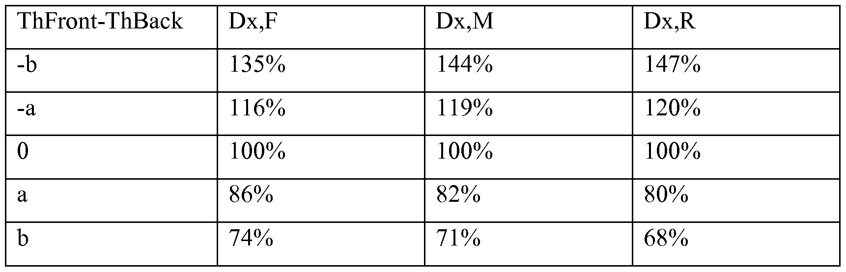
Table 15b


Tables 16a-c show the results of the mechanical stress test runs. FIGs 16A-C are illustrative plots of averages from Tables 16a-c of stresses along X, Y and Z-axes as a function of the differences in the thickness of front and back sections.
Baseline deformation and stress occurs when the front section thickness is equal to the back section thickness. The results indicate significantly less stress and less material deformation with increasing difference between the thickness of front and back sections, (i.e. increased eccentricity). Zero ("0") in Tables 16a-c refers to the baseline where the thickness of the front and back are equal, or the base is concentric (not eccentric). As a result the stress is set to be 100%. As the difference in thickness increases at the front, the measured stress deviates and decreases from 100%. Tables 16a-c show that as the thickness in the front of the eccentric base increases, the eccentric base is less susceptible to mechanical stress in the various regions of the front of the eccentric base from a low of about 37% to about 80%) as compared to the stress realized by a concentric base.
Table 16a


Table 16c

[0037] While the present invention is directed to valve guards that are secured via threads and fasteners to present a largely immovable valve guard, it is understood that embodiments of the present invention are contemplated whereby the valve guard is removable after attachment to the neck of the gas cylinder. It is the present industry standard for gas cylinders to be manufactured with threads on a neck. However, the scope of the present invention further contemplates adaptations whereby the base of the valve guard may be dimensioned to mate with threads found, for example, beyond the neck of the gas cylinder, or mated via a mating arrangement that does not require threads, etc.
[0038] The valve guards of the present invention are preferably made from materials that may be cast or molded and that conform to industry health and safety standards. An example of such a material is Nodular Iron. However, it is understood that innumerable other materials may be found to be suitable for use
as the valve guards of the present invention. Durable ceramics, plastics, composite materials, etc. may be used alone or in combination, in one or more layers, or as a laminate, etc.
[0039] According to embodiments of the present invention, at least one opening is present for access to the gas cylinder valve. Ideally, the gas valve, in preferred embodiments, is effectively encased within the valve guard such that the dimensions of the valve guard would cause the guard to strike or be struck by another object or surface, and inhibit such object, or surface from striking the valve. According to further embodiments, such an effect is achieved by the valve guards of the present invention. In other words, while possessing a predetermined dimension to protect the valve, the valve guards of the present invention via an access opening, substantially simultaneously allow for the servicing, inspection, and/or augmentation of the valve assembly, as well as cylinder identification, etc., without removing the valve guard.
[0040] In further embodiments, the present invention contemplates conserving material for the valve guard by machining at least one opening in the valve guard, preferably on the side of the valve guard opposing the main access opening for the valve maintenance. Indeed, according to embodiments of the present invention, as shown in the accompanying FIGs., when two additional openings are created in the side of the valve guard opposite the main access opening, a horizontal "rib" or cross-strut is formed. This rib is ideally positioned, according to preferred embodiments, at a height approximately equal to the height of the valve hand wheel to help guard against the valve hand wheel being struck by, or striking another object. In addition, the rib may be used as a surface for a lifting or moving means, for the purpose of automatically or manually moving or lifting the cylinder. It is further understood that the top of the valve guard also may be engaged by a lifting means through one or both of the openings for the purpose of automatically or manually moving, maneuvering, lifting, etc. the cylinder.
Through these and other embodiments of the invention, it is understood that the valve guards of the present invention provide adequate access to the valve while simultaneously protecting the valve from damage due to vertical or horizontal
impact, while also substantially simultaneously and significantly facilitating the handling and continuous tracking and identification of the entire gas cylinder.
[0041] According to embodiments of the present invention, the valve guards of the present invention may be adapted to include marking, tracking, monitoring, etc. features that allow one to encode or otherwise impart information pertaining to each gas cylinder to identify and monitor, for example, the location and origin, contents, date or arrival, etc. of the gas cylinder. See FIG. 13. As shown in FIGs. 17A and 17B, embodiments of the present invention contemplate alternate locations on the valve guard for placement of marking, tracing, etc. features. FIGs 17A and 17B show the valve guard as shown in FIGs. 5 A and 5B where valve guard 40 comprises a tracking device 80 that may be a supplemental tracking device preferably affixed to the underside of the top portion of valve guard 40. It is understood that the tracking device 80 may be incorporated in the valve guard 40 alone or in addition to the tracking device 72 shown in FIG. 13. The tracking device 80 therefore, according to embodiments of the present invention, may contain additional or redundant information. Such tracking device may be in the form of a chip or other device embedded or otherwise integrated preferably into an adherable medium such as, for example, a tape or other adherable feature. In one embodiment, the device 80 is an RFID adherable sticker. The sticker is preferably an UHF tag. As shown in FIG. 17, the device 80 is located on the valve guard 40 in a protected region, such as an interior surface. The presence of a tracking device 80, that may be a supplemental tracking device, provides redundancy with respect to tracking, locating, identifying, etc. a cylinder to which the valve guard is attached. Such redundancy is thought to take into account the possibility of damage or malfunction of the tracking device 72 (FIG. 13) that is located on the potentially exposed exterior surface of the valve guard 40. It is understood that one or more tracking devices 80 may be positioned at various locations on or within the valve guard.
[0042] Although the invention has been described in a preferred form with a certain degree of particularity, it is understood that the present invention of the preferred form has been made only by way of example and numerous changes in
the details of construction and combination and arrangement of parts may be resorted to without departing from the spirit and scope of the invention as hereinafter claimed. It is intended that the patent shall cover, by suitable expression in the appended claims, whatever features of patentable novelty exist in the invention disclosed.
Claims
1. A valve guard comprising:
a valve guard main body section, said main body section comprising at least one access opening, said main body section dimensioned to partially encase a neck section and valve of a gas cylinder; and
an eccentric base section comprising an inner wall dimensioned to mate with the neck section of the gas cylinder, and an outer wall, said eccentric base section comprising a variable thickness between the inner wall and the outer wall about the eccentric base section.
2. The valve guard of Claim 1 , wherein the valve guard is dimensioned to provide access for a means for lifting or moving the gas cylinder while substantially simultaneously at least partially enclosing a valve extending from a gas cylinder.
3. The valve guard of Claim 1, wherein the eccentric base section is discontinuous.
4. The valve guard of Claim 1, wherein the eccentric base section is integral with the main body section and the valve guard is removably engaged to the neck section of the gas cylinder.
5. The valve guard of Claim 1, wherein the eccentric base section comprises an inner surface and an outer surface, and wherein the inner surface comprises threads that mate with the neck section of the gas cylinder.
6. The valve guard of Claim 5, wherein the inner surface of the eccentric base section is substantially circular and the outer surface of the eccentric base section is substantially elliptical.
7. The valve guard of Claim 1 , wherein the valve guard provides access to the valve while simultaneously protecting the valve from damage.
8. The valve guard of Claim 1 , wherein the valve guard is made from a Nodular iron.
9. The valve guard of Claim 1, wherein the valve guard comprises at least one device to identify and monitor the gas cylinder.
10. The valve guard of Claim 1, wherein the eccentric base is discontinuous to create a gap, and wherein the thickness between the inner and outer walls of the eccentric base is greater adjacent the gap.
11. The valve guard of Claim 10, wherein the eccentric base comprises:
a first end and a second end with the gap occurring there between; and wherein said first and second ends each comprise a first and second end thickness extending between the inner and outer surface of the eccentric base adjacent the gap, and said first end has a first bore hole extending through the first end, and the second end has a second bore hole, said first and second bore holes positioned relative to one another to receive a fastener, said fastener having a substantially linear component that extends from the first end and into the second end.
12. A gas cylinder comprising:
a gas cylinder body having a base section and a neck section, said neck section comprising a threaded section;
a valve in intimate contact with the neck section;
a valve guard comprising a main body section, said main body section comprising at least one access opening, said main body section dimensioned to partially encase the valve, and an eccentric base section integral with said valve guard main body section, said eccentric base section comprising an inner wall having threads to mate with the threaded section on the neck section of the gas cylinder, and an outer wall, with a variable thickness about the eccentric base section occurring between the inner and outer walls about the eccentric base section.
13. The gas cylinder of Claim 12, wherein the inner wall of the eccentric base section is substantially circular and the outer wall of the eccentric base section is substantially elliptical.
14. The gas cylinder of Claim 12, wherein the eccentric base section is discontinuous, said eccentric base section having a first end and a second end.
15. The gas cylinder Claim 12 wherein the eccentric base section is discontinuous, said eccentric base section having a first end and a second end, said first and second ends positioned to form a gap there between; and
wherein said first and second ends each comprise a first and second end thickness extending between the inner and outer surface of the eccentric base adjacent the first and second ends, said first end having a first bore hole extending through the first end and the second end having a second bore hole, said first and second bore holes positioned relative to one another to receive a fastener, said fastener having a substantially linear component that extends from the first end into the second end.
16. A gas delivery system comprising the valve guard of Claim 1.
17. A gas delivery system comprising the gas cylinder of Claim 12.
18. A gas delivery system comprising the gas cylinder of Claim 15.
Applications Claiming Priority (2)
| Application Number | Priority Date | Filing Date | Title |
|---|---|---|---|
| US37980210P | 2010-09-03 | 2010-09-03 | |
| US61/379,802 | 2010-09-03 |
Publications (1)
| Publication Number | Publication Date |
|---|---|
| WO2012030882A1 true WO2012030882A1 (en) | 2012-03-08 |
Family
ID=44583504
Family Applications (1)
| Application Number | Title | Priority Date | Filing Date |
|---|---|---|---|
| PCT/US2011/049826 Ceased WO2012030882A1 (en) | 2010-09-03 | 2011-08-31 | Valve guard |
Country Status (1)
| Country | Link |
|---|---|
| WO (1) | WO2012030882A1 (en) |
Cited By (15)
| Publication number | Priority date | Publication date | Assignee | Title |
|---|---|---|---|---|
| WO2013156699A1 (en) * | 2012-04-19 | 2013-10-24 | L'air Liquide,Societe Anonyme Pour L'etude Et L'exploitation Des Procedes Georges Claude | Protective cap for a pressurised fluid cylinder valve and production method thereof |
| FR2991751A1 (en) * | 2012-06-11 | 2013-12-13 | Air Liquide | PRESSURIZED FLUID DELIVERY DEVICE |
| FR3011612A1 (en) * | 2013-10-07 | 2015-04-10 | Rovip | PROTECTIVE CAP FOR GAS BOTTLE |
| WO2015150487A1 (en) * | 2014-04-02 | 2015-10-08 | Compagnie Des Gaz De Petrole Primagaz | Handle for a gas cylinder, comprising a level sensor |
| FR3025587A1 (en) * | 2014-09-09 | 2016-03-11 | Air Liquide | GAS CONTAINER HAVING A PROTECTIVE COVERAGE INCORPORATING A TRANSMITTING / RECEIVING ANTENNA |
| US9775524B2 (en) | 2011-01-06 | 2017-10-03 | Medsolve Limited | Apparatus and method of assessing a narrowing in a fluid filled tube |
| GB2556318A (en) * | 2016-07-11 | 2018-05-30 | Linde Ag | A Guard for a cylinder of pressurised gas |
| RU188328U1 (en) * | 2018-09-12 | 2019-04-08 | Общество с ограниченной ответственностью Фирма "Криоген" | GAS CYLINDER VALVE PROTECTIVE CAP |
| US10390768B2 (en) | 2011-08-20 | 2019-08-27 | Volcano Corporation | Devices, systems, and methods for visually depicting a vessel and evaluating treatment options |
| CN111853539A (en) * | 2020-08-12 | 2020-10-30 | 上海万亘实业有限公司 | A bottle cap and pressure vessel |
| US10888232B2 (en) | 2011-08-20 | 2021-01-12 | Philips Image Guided Therapy Corporation | Devices, systems, and methods for assessing a vessel |
| US10912463B2 (en) | 2011-08-20 | 2021-02-09 | Philips Image Guided Therapy Corporation | Devices, systems, and methods for assessing a vessel |
| USD1019897S1 (en) | 2021-05-31 | 2024-03-26 | Gce Holding Ab | Regulator |
| USD1025299S1 (en) | 2021-05-31 | 2024-04-30 | Gce Holding Ab | Regulator |
| USD1036625S1 (en) | 2021-05-31 | 2024-07-23 | Gce Group Ab | Regulator |
Citations (7)
| Publication number | Priority date | Publication date | Assignee | Title |
|---|---|---|---|---|
| FR1007977A (en) * | 1949-04-13 | 1952-05-12 | Protective cap for pressurized fluid bottles | |
| FR2507574A1 (en) * | 1981-06-16 | 1982-12-17 | Mousserolles Fonderies Atel | Cap for liquid gas bottle - has top and side holes large enough for refilling without cap removal |
| EP0109707A1 (en) * | 1982-11-12 | 1984-05-30 | N.V. W.A. Hoek's Machine- en Zuurstoffabriek | An assembly for recognizing gas cylinders |
| EP0189046A2 (en) * | 1985-01-24 | 1986-07-30 | Messer Griesheim Gmbh | Protecting device for steel gas bottle valves |
| WO1991004197A1 (en) * | 1989-09-25 | 1991-04-04 | Sakae Kitsuda | Safety cylinder cap |
| FR2681123A1 (en) * | 1991-09-09 | 1993-03-12 | Mousserolles Fonderies Atelier | Protection devices for industrial, domestic, and medical gas cylinders (bottles) provided with a self-tightening safety collar |
| FR2729739A1 (en) * | 1995-01-25 | 1996-07-26 | Soc D Anciennes Fonderies Et A | PROTECTORS FOR INDUSTRIAL, DOMESTIC OR MEDICAL GAS BOTTLES PROVIDED WITH A SELF-TIGHTENING SAFETY COLLAR |
-
2011
- 2011-08-31 WO PCT/US2011/049826 patent/WO2012030882A1/en not_active Ceased
Patent Citations (7)
| Publication number | Priority date | Publication date | Assignee | Title |
|---|---|---|---|---|
| FR1007977A (en) * | 1949-04-13 | 1952-05-12 | Protective cap for pressurized fluid bottles | |
| FR2507574A1 (en) * | 1981-06-16 | 1982-12-17 | Mousserolles Fonderies Atel | Cap for liquid gas bottle - has top and side holes large enough for refilling without cap removal |
| EP0109707A1 (en) * | 1982-11-12 | 1984-05-30 | N.V. W.A. Hoek's Machine- en Zuurstoffabriek | An assembly for recognizing gas cylinders |
| EP0189046A2 (en) * | 1985-01-24 | 1986-07-30 | Messer Griesheim Gmbh | Protecting device for steel gas bottle valves |
| WO1991004197A1 (en) * | 1989-09-25 | 1991-04-04 | Sakae Kitsuda | Safety cylinder cap |
| FR2681123A1 (en) * | 1991-09-09 | 1993-03-12 | Mousserolles Fonderies Atelier | Protection devices for industrial, domestic, and medical gas cylinders (bottles) provided with a self-tightening safety collar |
| FR2729739A1 (en) * | 1995-01-25 | 1996-07-26 | Soc D Anciennes Fonderies Et A | PROTECTORS FOR INDUSTRIAL, DOMESTIC OR MEDICAL GAS BOTTLES PROVIDED WITH A SELF-TIGHTENING SAFETY COLLAR |
Cited By (27)
| Publication number | Priority date | Publication date | Assignee | Title |
|---|---|---|---|---|
| US9775524B2 (en) | 2011-01-06 | 2017-10-03 | Medsolve Limited | Apparatus and method of assessing a narrowing in a fluid filled tube |
| US12383147B2 (en) | 2011-01-06 | 2025-08-12 | Medsolve Pte Ltd | Apparatus and method of assessing a narrowing in a fluid fileld tube |
| US11389068B2 (en) | 2011-01-06 | 2022-07-19 | Medsolve Limited | Apparatus and method of assessing a narrowing in a fluid filled tube |
| US10888232B2 (en) | 2011-08-20 | 2021-01-12 | Philips Image Guided Therapy Corporation | Devices, systems, and methods for assessing a vessel |
| US10390768B2 (en) | 2011-08-20 | 2019-08-27 | Volcano Corporation | Devices, systems, and methods for visually depicting a vessel and evaluating treatment options |
| US11950884B2 (en) | 2011-08-20 | 2024-04-09 | Philips Image Guided Therapy Corporation | Devices, systems, and methods for assessing a vessel |
| US11122980B2 (en) | 2011-08-20 | 2021-09-21 | Imperial College Of Science, Technology And Medicine | Devices, systems, and methods for visually depicting a vessel and evaluating treatment options |
| US10912463B2 (en) | 2011-08-20 | 2021-02-09 | Philips Image Guided Therapy Corporation | Devices, systems, and methods for assessing a vessel |
| RU2604978C2 (en) * | 2012-04-19 | 2016-12-20 | Л'Эр Ликид, Сосьете Аноним Пур Л'Этюд Э Л'Эксплуатасьон Де Проседе Жорж Клод | Protective cap for valve for compressed air cylinder and its production method |
| WO2013156699A1 (en) * | 2012-04-19 | 2013-10-24 | L'air Liquide,Societe Anonyme Pour L'etude Et L'exploitation Des Procedes Georges Claude | Protective cap for a pressurised fluid cylinder valve and production method thereof |
| AU2013250997B2 (en) * | 2012-04-19 | 2017-02-02 | L'air Liquide,Societe Anonyme Pour L'etude Et L'exploitation Des Procedes Georges Claude | Protective cap for a pressurised fluid cylinder valve and production method thereof |
| RU2617646C2 (en) * | 2012-04-19 | 2017-04-25 | Л'Эр Ликид, Сосьете Аноним Пур Л'Этюд Э Л'Эксплуатасьон Де Проседе Жорж Клод | Protecting cap for balloon valve with fluid under pressure and method of its production |
| WO2013156698A1 (en) * | 2012-04-19 | 2013-10-24 | L'air Liquide,Societe Anonyme Pour L'etude Et L'exploitation Des Procedes Georges Claude | Protective cap for a pressurised fluid cylinder valve and production method thereof |
| FR2989759A1 (en) * | 2012-04-19 | 2013-10-25 | Air Liquide | PROTECTIVE HAT FOR PRESSURIZED FLUID BOTTLE VALVE AND METHOD OF MANUFACTURING THE SAME |
| EP2674660A3 (en) * | 2012-06-11 | 2018-02-14 | L'air Liquide, Societe Anonyme Pour L'etude Et L'exploitation Des Procedes Georges Claude | Device for delivering fluid under pressure |
| FR2991751A1 (en) * | 2012-06-11 | 2013-12-13 | Air Liquide | PRESSURIZED FLUID DELIVERY DEVICE |
| FR3011612A1 (en) * | 2013-10-07 | 2015-04-10 | Rovip | PROTECTIVE CAP FOR GAS BOTTLE |
| FR3019623A1 (en) * | 2014-04-02 | 2015-10-09 | Gaz De Petrole | HANDLE FOR A MOBILE TANK, COMPRISING A COMMUNICATION DEVICE |
| WO2015150487A1 (en) * | 2014-04-02 | 2015-10-08 | Compagnie Des Gaz De Petrole Primagaz | Handle for a gas cylinder, comprising a level sensor |
| EP2998636A1 (en) * | 2014-09-09 | 2016-03-23 | L'air Liquide, Societe Anonyme Pour L'etude Et L'exploitation Des Procedes Georges Claude | Gas tank having a protective casing including a transmitting/receiving antenna |
| FR3025587A1 (en) * | 2014-09-09 | 2016-03-11 | Air Liquide | GAS CONTAINER HAVING A PROTECTIVE COVERAGE INCORPORATING A TRANSMITTING / RECEIVING ANTENNA |
| GB2556318A (en) * | 2016-07-11 | 2018-05-30 | Linde Ag | A Guard for a cylinder of pressurised gas |
| RU188328U1 (en) * | 2018-09-12 | 2019-04-08 | Общество с ограниченной ответственностью Фирма "Криоген" | GAS CYLINDER VALVE PROTECTIVE CAP |
| CN111853539A (en) * | 2020-08-12 | 2020-10-30 | 上海万亘实业有限公司 | A bottle cap and pressure vessel |
| USD1019897S1 (en) | 2021-05-31 | 2024-03-26 | Gce Holding Ab | Regulator |
| USD1025299S1 (en) | 2021-05-31 | 2024-04-30 | Gce Holding Ab | Regulator |
| USD1036625S1 (en) | 2021-05-31 | 2024-07-23 | Gce Group Ab | Regulator |
Similar Documents
| Publication | Publication Date | Title |
|---|---|---|
| WO2012030882A1 (en) | Valve guard | |
| US6955194B2 (en) | Protected integral cylinder valve, gas pressure regulator and flow meter, and method for refilling a gas cylinder so equipped | |
| US20100212765A1 (en) | End protector system for tubular goods | |
| US9046220B2 (en) | Port/liner assembly for pressure vessel | |
| EP0109707A1 (en) | An assembly for recognizing gas cylinders | |
| CA2877707C (en) | Gussets for reinforcement in tank cars and tank cars including gussets | |
| EP1143191B1 (en) | Full jacket gas cylinder | |
| AU2000271317A1 (en) | Full jacket gas cylinder | |
| EP1156266A2 (en) | Support fot identification data and said data for a composite pressure vessel | |
| EP2783151B1 (en) | Improved boss for composite pressure container | |
| TWI526648B (en) | Protection structure for gas cylinder and valve arrangement | |
| EP1744094A2 (en) | A cylinder | |
| EP3093548B1 (en) | Protective casing for cylinder for pressurized gases | |
| US11377224B2 (en) | System comprising an air intake of an aircraft engine and an inflatable protection item for said air intake | |
| WO2016058951A2 (en) | Valve guard | |
| US6871518B2 (en) | Gas system component inlet or outlet connection retaining bracket | |
| US10724687B2 (en) | Compressed gas cylinder quick release safety cap | |
| RU2586467C2 (en) | Locking device for container for transporting radioactive materials | |
| CN223677565U (en) | A liquefied natural gas storage tank | |
| JP6881099B2 (en) | High pressure tank | |
| BOOM | Instruction manual | |
| US11378198B2 (en) | Valve bonnet accessory | |
| CN215414349U (en) | Hydraulic nut pressure detection assembly | |
| Martinez et al. | Regulatory testing and posttest analysis of the DPP-3 type b shipping container for NCT and HAC tests | |
| JPH04124969U (en) | Gas cylinder packaging equipment |
Legal Events
| Date | Code | Title | Description |
|---|---|---|---|
| 121 | Ep: the epo has been informed by wipo that ep was designated in this application |
Ref document number: 11752734 Country of ref document: EP Kind code of ref document: A1 |
|
| NENP | Non-entry into the national phase |
Ref country code: DE |
|
| 122 | Ep: pct application non-entry in european phase |
Ref document number: 11752734 Country of ref document: EP Kind code of ref document: A1 |