WO2011140993A1 - Intelligent traffic safety system based on comprehensive state detection and decision method thereof - Google Patents
Intelligent traffic safety system based on comprehensive state detection and decision method thereof Download PDFInfo
- Publication number
- WO2011140993A1 WO2011140993A1 PCT/CN2011/074013 CN2011074013W WO2011140993A1 WO 2011140993 A1 WO2011140993 A1 WO 2011140993A1 CN 2011074013 W CN2011074013 W CN 2011074013W WO 2011140993 A1 WO2011140993 A1 WO 2011140993A1
- Authority
- WO
- WIPO (PCT)
- Prior art keywords
- module
- vehicle
- driver
- unit
- car
- Prior art date
- Legal status (The legal status is an assumption and is not a legal conclusion. Google has not performed a legal analysis and makes no representation as to the accuracy of the status listed.)
- Ceased
Links
Classifications
-
- B—PERFORMING OPERATIONS; TRANSPORTING
- B60—VEHICLES IN GENERAL
- B60K—ARRANGEMENT OR MOUNTING OF PROPULSION UNITS OR OF TRANSMISSIONS IN VEHICLES; ARRANGEMENT OR MOUNTING OF PLURAL DIVERSE PRIME-MOVERS IN VEHICLES; AUXILIARY DRIVES FOR VEHICLES; INSTRUMENTATION OR DASHBOARDS FOR VEHICLES; ARRANGEMENTS IN CONNECTION WITH COOLING, AIR INTAKE, GAS EXHAUST OR FUEL SUPPLY OF PROPULSION UNITS IN VEHICLES
- B60K28/00—Safety devices for propulsion-unit control, specially adapted for, or arranged in, vehicles, e.g. preventing fuel supply or ignition in the event of potentially dangerous conditions
- B60K28/02—Safety devices for propulsion-unit control, specially adapted for, or arranged in, vehicles, e.g. preventing fuel supply or ignition in the event of potentially dangerous conditions responsive to conditions relating to the driver
-
- B—PERFORMING OPERATIONS; TRANSPORTING
- B60—VEHICLES IN GENERAL
- B60W—CONJOINT CONTROL OF VEHICLE SUB-UNITS OF DIFFERENT TYPE OR DIFFERENT FUNCTION; CONTROL SYSTEMS SPECIALLY ADAPTED FOR HYBRID VEHICLES; ROAD VEHICLE DRIVE CONTROL SYSTEMS FOR PURPOSES NOT RELATED TO THE CONTROL OF A PARTICULAR SUB-UNIT
- B60W40/00—Estimation or calculation of non-directly measurable driving parameters for road vehicle drive control systems not related to the control of a particular sub unit, e.g. by using mathematical models
- B60W40/08—Estimation or calculation of non-directly measurable driving parameters for road vehicle drive control systems not related to the control of a particular sub unit, e.g. by using mathematical models related to drivers or passengers
- B60W40/09—Driving style or behaviour
-
- B—PERFORMING OPERATIONS; TRANSPORTING
- B60—VEHICLES IN GENERAL
- B60K—ARRANGEMENT OR MOUNTING OF PROPULSION UNITS OR OF TRANSMISSIONS IN VEHICLES; ARRANGEMENT OR MOUNTING OF PLURAL DIVERSE PRIME-MOVERS IN VEHICLES; AUXILIARY DRIVES FOR VEHICLES; INSTRUMENTATION OR DASHBOARDS FOR VEHICLES; ARRANGEMENTS IN CONNECTION WITH COOLING, AIR INTAKE, GAS EXHAUST OR FUEL SUPPLY OF PROPULSION UNITS IN VEHICLES
- B60K28/00—Safety devices for propulsion-unit control, specially adapted for, or arranged in, vehicles, e.g. preventing fuel supply or ignition in the event of potentially dangerous conditions
- B60K28/10—Safety devices for propulsion-unit control, specially adapted for, or arranged in, vehicles, e.g. preventing fuel supply or ignition in the event of potentially dangerous conditions responsive to conditions relating to the vehicle
-
- B—PERFORMING OPERATIONS; TRANSPORTING
- B60—VEHICLES IN GENERAL
- B60W—CONJOINT CONTROL OF VEHICLE SUB-UNITS OF DIFFERENT TYPE OR DIFFERENT FUNCTION; CONTROL SYSTEMS SPECIALLY ADAPTED FOR HYBRID VEHICLES; ROAD VEHICLE DRIVE CONTROL SYSTEMS FOR PURPOSES NOT RELATED TO THE CONTROL OF A PARTICULAR SUB-UNIT
- B60W30/00—Purposes of road vehicle drive control systems not related to the control of a particular sub-unit, e.g. of systems using conjoint control of vehicle sub-units
- B60W30/08—Active safety systems predicting or avoiding probable or impending collision or attempting to minimise its consequences
- B60W30/095—Predicting travel path or likelihood of collision
- B60W30/0953—Predicting travel path or likelihood of collision the prediction being responsive to vehicle dynamic parameters
-
- B—PERFORMING OPERATIONS; TRANSPORTING
- B60—VEHICLES IN GENERAL
- B60W—CONJOINT CONTROL OF VEHICLE SUB-UNITS OF DIFFERENT TYPE OR DIFFERENT FUNCTION; CONTROL SYSTEMS SPECIALLY ADAPTED FOR HYBRID VEHICLES; ROAD VEHICLE DRIVE CONTROL SYSTEMS FOR PURPOSES NOT RELATED TO THE CONTROL OF A PARTICULAR SUB-UNIT
- B60W30/00—Purposes of road vehicle drive control systems not related to the control of a particular sub-unit, e.g. of systems using conjoint control of vehicle sub-units
- B60W30/08—Active safety systems predicting or avoiding probable or impending collision or attempting to minimise its consequences
- B60W30/095—Predicting travel path or likelihood of collision
- B60W30/0956—Predicting travel path or likelihood of collision the prediction being responsive to traffic or environmental parameters
-
- B—PERFORMING OPERATIONS; TRANSPORTING
- B60—VEHICLES IN GENERAL
- B60W—CONJOINT CONTROL OF VEHICLE SUB-UNITS OF DIFFERENT TYPE OR DIFFERENT FUNCTION; CONTROL SYSTEMS SPECIALLY ADAPTED FOR HYBRID VEHICLES; ROAD VEHICLE DRIVE CONTROL SYSTEMS FOR PURPOSES NOT RELATED TO THE CONTROL OF A PARTICULAR SUB-UNIT
- B60W2540/00—Input parameters relating to occupants
- B60W2540/043—Identity of occupants
-
- B—PERFORMING OPERATIONS; TRANSPORTING
- B60—VEHICLES IN GENERAL
- B60W—CONJOINT CONTROL OF VEHICLE SUB-UNITS OF DIFFERENT TYPE OR DIFFERENT FUNCTION; CONTROL SYSTEMS SPECIALLY ADAPTED FOR HYBRID VEHICLES; ROAD VEHICLE DRIVE CONTROL SYSTEMS FOR PURPOSES NOT RELATED TO THE CONTROL OF A PARTICULAR SUB-UNIT
- B60W2540/00—Input parameters relating to occupants
- B60W2540/045—Occupant permissions
-
- B—PERFORMING OPERATIONS; TRANSPORTING
- B60—VEHICLES IN GENERAL
- B60W—CONJOINT CONTROL OF VEHICLE SUB-UNITS OF DIFFERENT TYPE OR DIFFERENT FUNCTION; CONTROL SYSTEMS SPECIALLY ADAPTED FOR HYBRID VEHICLES; ROAD VEHICLE DRIVE CONTROL SYSTEMS FOR PURPOSES NOT RELATED TO THE CONTROL OF A PARTICULAR SUB-UNIT
- B60W2540/00—Input parameters relating to occupants
- B60W2540/223—Posture, e.g. hand, foot, or seat position, turned or inclined
-
- B—PERFORMING OPERATIONS; TRANSPORTING
- B60—VEHICLES IN GENERAL
- B60W—CONJOINT CONTROL OF VEHICLE SUB-UNITS OF DIFFERENT TYPE OR DIFFERENT FUNCTION; CONTROL SYSTEMS SPECIALLY ADAPTED FOR HYBRID VEHICLES; ROAD VEHICLE DRIVE CONTROL SYSTEMS FOR PURPOSES NOT RELATED TO THE CONTROL OF A PARTICULAR SUB-UNIT
- B60W2540/00—Input parameters relating to occupants
- B60W2540/229—Attention level, e.g. attentive to driving, reading or sleeping
-
- B—PERFORMING OPERATIONS; TRANSPORTING
- B60—VEHICLES IN GENERAL
- B60W—CONJOINT CONTROL OF VEHICLE SUB-UNITS OF DIFFERENT TYPE OR DIFFERENT FUNCTION; CONTROL SYSTEMS SPECIALLY ADAPTED FOR HYBRID VEHICLES; ROAD VEHICLE DRIVE CONTROL SYSTEMS FOR PURPOSES NOT RELATED TO THE CONTROL OF A PARTICULAR SUB-UNIT
- B60W2540/00—Input parameters relating to occupants
- B60W2540/24—Drug level, e.g. alcohol
-
- B—PERFORMING OPERATIONS; TRANSPORTING
- B60—VEHICLES IN GENERAL
- B60W—CONJOINT CONTROL OF VEHICLE SUB-UNITS OF DIFFERENT TYPE OR DIFFERENT FUNCTION; CONTROL SYSTEMS SPECIALLY ADAPTED FOR HYBRID VEHICLES; ROAD VEHICLE DRIVE CONTROL SYSTEMS FOR PURPOSES NOT RELATED TO THE CONTROL OF A PARTICULAR SUB-UNIT
- B60W2540/00—Input parameters relating to occupants
- B60W2540/26—Incapacity
-
- B—PERFORMING OPERATIONS; TRANSPORTING
- B60—VEHICLES IN GENERAL
- B60W—CONJOINT CONTROL OF VEHICLE SUB-UNITS OF DIFFERENT TYPE OR DIFFERENT FUNCTION; CONTROL SYSTEMS SPECIALLY ADAPTED FOR HYBRID VEHICLES; ROAD VEHICLE DRIVE CONTROL SYSTEMS FOR PURPOSES NOT RELATED TO THE CONTROL OF A PARTICULAR SUB-UNIT
- B60W2552/00—Input parameters relating to infrastructure
- B60W2552/10—Number of lanes
-
- B—PERFORMING OPERATIONS; TRANSPORTING
- B60—VEHICLES IN GENERAL
- B60W—CONJOINT CONTROL OF VEHICLE SUB-UNITS OF DIFFERENT TYPE OR DIFFERENT FUNCTION; CONTROL SYSTEMS SPECIALLY ADAPTED FOR HYBRID VEHICLES; ROAD VEHICLE DRIVE CONTROL SYSTEMS FOR PURPOSES NOT RELATED TO THE CONTROL OF A PARTICULAR SUB-UNIT
- B60W2552/00—Input parameters relating to infrastructure
- B60W2552/15—Road slope, i.e. the inclination of a road segment in the longitudinal direction
-
- B—PERFORMING OPERATIONS; TRANSPORTING
- B60—VEHICLES IN GENERAL
- B60W—CONJOINT CONTROL OF VEHICLE SUB-UNITS OF DIFFERENT TYPE OR DIFFERENT FUNCTION; CONTROL SYSTEMS SPECIALLY ADAPTED FOR HYBRID VEHICLES; ROAD VEHICLE DRIVE CONTROL SYSTEMS FOR PURPOSES NOT RELATED TO THE CONTROL OF A PARTICULAR SUB-UNIT
- B60W2552/00—Input parameters relating to infrastructure
- B60W2552/35—Road bumpiness, e.g. potholes
-
- B—PERFORMING OPERATIONS; TRANSPORTING
- B60—VEHICLES IN GENERAL
- B60W—CONJOINT CONTROL OF VEHICLE SUB-UNITS OF DIFFERENT TYPE OR DIFFERENT FUNCTION; CONTROL SYSTEMS SPECIALLY ADAPTED FOR HYBRID VEHICLES; ROAD VEHICLE DRIVE CONTROL SYSTEMS FOR PURPOSES NOT RELATED TO THE CONTROL OF A PARTICULAR SUB-UNIT
- B60W2552/00—Input parameters relating to infrastructure
- B60W2552/50—Barriers
-
- B—PERFORMING OPERATIONS; TRANSPORTING
- B60—VEHICLES IN GENERAL
- B60W—CONJOINT CONTROL OF VEHICLE SUB-UNITS OF DIFFERENT TYPE OR DIFFERENT FUNCTION; CONTROL SYSTEMS SPECIALLY ADAPTED FOR HYBRID VEHICLES; ROAD VEHICLE DRIVE CONTROL SYSTEMS FOR PURPOSES NOT RELATED TO THE CONTROL OF A PARTICULAR SUB-UNIT
- B60W2554/00—Input parameters relating to objects
- B60W2554/40—Dynamic objects, e.g. animals, windblown objects
- B60W2554/402—Type
- B60W2554/4029—Pedestrians
-
- B—PERFORMING OPERATIONS; TRANSPORTING
- B60—VEHICLES IN GENERAL
- B60W—CONJOINT CONTROL OF VEHICLE SUB-UNITS OF DIFFERENT TYPE OR DIFFERENT FUNCTION; CONTROL SYSTEMS SPECIALLY ADAPTED FOR HYBRID VEHICLES; ROAD VEHICLE DRIVE CONTROL SYSTEMS FOR PURPOSES NOT RELATED TO THE CONTROL OF A PARTICULAR SUB-UNIT
- B60W2554/00—Input parameters relating to objects
- B60W2554/40—Dynamic objects, e.g. animals, windblown objects
- B60W2554/406—Traffic density
-
- B—PERFORMING OPERATIONS; TRANSPORTING
- B60—VEHICLES IN GENERAL
- B60W—CONJOINT CONTROL OF VEHICLE SUB-UNITS OF DIFFERENT TYPE OR DIFFERENT FUNCTION; CONTROL SYSTEMS SPECIALLY ADAPTED FOR HYBRID VEHICLES; ROAD VEHICLE DRIVE CONTROL SYSTEMS FOR PURPOSES NOT RELATED TO THE CONTROL OF A PARTICULAR SUB-UNIT
- B60W2554/00—Input parameters relating to objects
- B60W2554/80—Spatial relation or speed relative to objects
-
- Y—GENERAL TAGGING OF NEW TECHNOLOGICAL DEVELOPMENTS; GENERAL TAGGING OF CROSS-SECTIONAL TECHNOLOGIES SPANNING OVER SEVERAL SECTIONS OF THE IPC; TECHNICAL SUBJECTS COVERED BY FORMER USPC CROSS-REFERENCE ART COLLECTIONS [XRACs] AND DIGESTS
- Y02—TECHNOLOGIES OR APPLICATIONS FOR MITIGATION OR ADAPTATION AGAINST CLIMATE CHANGE
- Y02T—CLIMATE CHANGE MITIGATION TECHNOLOGIES RELATED TO TRANSPORTATION
- Y02T10/00—Road transport of goods or passengers
- Y02T10/80—Technologies aiming to reduce greenhouse gasses emissions common to all road transportation technologies
- Y02T10/84—Data processing systems or methods, management, administration
Definitions
- the intelligent traffic safety system includes a human condition detecting unit, a vehicle condition detecting unit, a road condition detecting unit, an intelligent decision unit, a driver alarm unit, a vehicle mandatory processing unit, an obstacle alarm unit, a follow-up object alarm unit, and a collision after-effect alarm unit; among them,
- the intelligent traffic safety system is composed of a server supporting cloud computing, a plurality of in-vehicle electronic terminals installed on the automobile, and a cloud monitoring terminal installed on the traffic infrastructure;
- the wireless network is built by Zi gBee between each in-vehicle electronic terminal.
- the vehicle anti-theft network device comprises a pyroelectric sensor, a cloud platform, a camera, a front-end embedded system and a front-end detection module;
- the car anti-theft network device further includes a pickup, the pickup is connected to an audio input processing interface in the front-end embedded system, and the audio input processing interface is connected to the front-end embedded central unit.
- the microwave radar in the vehicle active anti-collision device is installed around the vehicle body, the microwave radar includes a transceiver front end and a signal processing back end, and the power transmission line, the control line, and the simulation are transmitted between the transceiver front end and the signal processing back end.
- the modulated signal line and the echo signal line are connected, and the signal processing back end is connected to the automobile bus, and then connected to the transmission system and the braking system of the vehicle to control the motion state of the vehicle.
- the arc length interval is determined according to the length of the car and the degree of road congestion.
- a plurality of points (for example, m points) are selected according to the predetermined time interval between the two adjacent points before and after the road, and the two-dimensional dynamic orientation is obtained according to the geographic parameters of each point.
- Figure 4 is a schematic view showing the mounting points of components such as a camera in a car anti-theft network device
- FIG. 6 is a schematic diagram showing the composition principle of an electronic terminal for implementing an alcohol level monitoring function
- FIG. 9 is a schematic diagram of an operation mode of an eye opening and closing detection module
- FIG. 11 is a schematic diagram of an operation mode of a head motion tracking module
- the remarkable feature of the invention is that the mechanism of inducing collision accidents is comprehensively considered by human condition information, road condition information and vehicle condition information, and the general intrinsic nature of various automobile collision phenomena is analyzed, and the collision avoidance prediction is combed out.
- the intelligent traffic safety system based on integrated state detection provided by the present invention adopts the design scheme shown in FIG.
- the human condition detection means that the driver's ability is detected and expressed in time (seconds): from the time when the driver gets the collision alarm to the time when the driver completes the manipulation.
- the human ability here mainly includes two aspects. One is whether the feeling is correct, whether the mind is clear, and expressed by the ability to respond. Second, whether the hands and feet are beneficial, expressed by the ability to handle. According to the driver's control characteristics of the vehicle, it is divided into three basic detection modules: driver identification and basic ability detection 1 1. Driver alcohol detection 12 and driver fatigue detection 13.
- the present invention is implemented by the vehicle anti-theft network device shown in FIG.
- the car anti-theft network device consists of the following components: pyroelectric sensor, pan/tilt, camera, pickup, acousto-optic generator, front-end embedded module and front-end detection module.
- the front-end embedded module is centered on the front-end embedded central unit, and further includes a power input module, a pyroelectric interface circuit, a pan-tilt control circuit, a video input processing interface, an audio input processing interface, a video output processing interface, and sound and light generation.
- Interface car control interface, wireless communication module and antenna, navigation and positioning module and antenna and WLAN module and antenna.
- the wireless communication module and the antenna are used for wireless communication of the wide area network, such as the GSM/GPRS/3G/4G communication module and the corresponding SIM/USIM card.
- the navigation and positioning module and antenna can support satellite information such as US GPS, Russian GNNS, European Galileo, China Beidou 2 or inertial navigation system for navigation and positioning, and can know the longitude and latitude of the vehicle in real time, so that it can be used to request specific time.
- the default client is notified by the server.
- the WLAN module and the antenna are used to implement wireless communication in the local area network.
- the on-site embedded server consists of a hardware component and corresponding field processing software. Where the hardware part is embedded The central processing unit is centered, and the remaining power input interfaces, driver sensor interfaces, pan/tilt control circuits, video interfaces and analog-to-digital conversion circuits, visible blowpipe pneumatic interfaces, alcohol sensitive circuits, digital-to-analog conversion and video processing circuits, The acousto-optic generator interface, the car start switch interface, the navigation and positioning circuit and the antenna, the remote wireless communication interface and the antenna are respectively connected to the embedded central processing unit.
- the remote wireless monitoring terminal can communicate with the remote wireless communication interface and the antenna for data, sound and video.
- the on-site embedded server can periodically check (can be set, such as every hour at night) to check the driver's alcohol level, and the remote monitoring terminal can also check the driver's alcohol level at any time. It can be forcibly turned off when it is found that it is too much.
- the coefficients in parentheses are the effects of alcohol on the ability to respond and maneuverability.
- Fatigue mainly leads to a decrease in driver's handling ability, and indirectly leads to a slow feeling of sound and color and a slow response to the brain.
- Statistics show that traffic accidents caused by fatigue/sleeping account for about ⁇ % of the total number of traffic accidents, accounting for serious traffic accidents, and accounting for traffic accidents on heavy trucks and highways. To this end, driver fatigue testing is specifically set up in this intelligent traffic safety system.
- the figure shows the schematic principle of the driver fatigue detection electronic terminal.
- the driver fatigue detection electronic terminal includes the following components: a camera, a pan/tilt, an acousto-optic generator, a front-end embedded module, and a front-end application module.
- the front-end embedded module is centered on the front-end embedded central unit, and further includes a power input module, a video interface and an analog-to-digital conversion circuit, a pan/tilt control circuit, a digital-to-analog conversion and video processing circuit, an acousto-optic generator interface, and an automobile operation. Interface, wireless communication module and antenna, navigation positioning module and antenna.
- the front-end embedded central unit is respectively connected with a power input module, a video interface and an analog-to-digital conversion circuit, a pan/tilt control circuit, a digital-to-analog conversion and video processing circuit, an acousto-optic generator interface, and a steam Vehicle control interface, wireless communication module and antenna, navigation positioning module and antenna.
- the front-end embedded central unit is also connected to the front-end application module.
- the front-end application module is configured to execute an algorithm for detecting an eye opening and closing state, a yawning state, and a head motion state, and makes a comprehensive judgment.
- the front-end embedded central unit includes the processor hardware and corresponding driver and operating system software. It is installed in the appropriate position in the car, and can be realized by ARM series chip, FPGA, DSP or single chip microcomputer, and has its own clock.
- the pan/tilt control circuit is used to provide pan/tilt motion and camera lens telescoping drive commands to ensure a sufficiently large and complete driver's head video image.
- the vehicle control interface is connected to the vehicle's own operating device for manipulating the car's own brakes, horns, and the like.
- the output of the car battery is directly connected to the power input interface to supply power to the relevant equipment in the driver's fatigue detection electronic terminal.
- the wireless communication module and antenna are used for wireless communication of the wide area network, such as the GSM/GPRS/3G communication module and the corresponding SIM/USIM card.
- the navigation positioning module and antenna can support satellite information such as US GPS, Russian GNNS, European Galileo, China Beidou 2 or inertial navigation system for navigation and positioning, and can know the longitude and latitude of the vehicle in real time, so that it can be used to request specific time.
- the default client is notified by the server.
- the sound and light generator is connected to the sound and light generator interface.
- the acousto-optic generator can include a sound generator, a light (which can emit red, orange, yellow, green, etc.) or a video display.
- the face detection module is used to find the position of the face in the image for the input single frame image data, and the position of the face is represented by a rectangular frame.
- the face feature point locating module is used to obtain the facial features of the face from the input single frame image data, and the facial features position is represented by a coordinate sequence of a plurality of points.
- Figure 11 shows the operating mode of the head motion tracking module.
- the facial features of the face can be obtained.
- the head position is calculated for each frame of the image, and the head movement trajectory can be obtained by combining the positioning results of the facial features.
- the comprehensive evaluation module outputs the detection result to be awake. Allowing the car to run normally, the fatigue level indicator on the car embedded device screen is green.
- the comprehensive evaluation module detects the result as moderate fatigue.
- the fatigue level indicator on the acousto-optic generator is shown as orange flashing, and an alarm sounds to the driver, the remote server, and the preset client. It is recommended that the driver park over.
- the comprehensive evaluation module detects the result as high fatigue.
- the function of the reliable starting unit in the vehicle's upper module is:
- the vehicle's upper module knows that the car starts and runs smoothly from the vehicle information interface such as the car CAN bus or GPS receiver, but has not obtained the upload data of a certain tire lower module. , the command is sent to the lower module of the tire to request uploading data, or the active/standby switch of the motion sensing sensor is required, otherwise the communication connection is switched.
- the car determines the arc length interval, and select multiple points according to the interval between the two points before and after the road, for example, after the car selects ⁇ , ⁇ two points, the front of the car selects £>, , ⁇ (7 Four points, the coordinates of the dynamic azimuth coordinate system can be obtained according to the latitude and longitude of each point of A, ⁇ , C, D, ⁇ , F, G, and two column vectors are recorded.
- the interface circuit includes a preamplifier, a matched filter, an automatic gain amplifying circuit (AGC amplifying circuit), a modulated signal filter, and a power adjusting circuit.
- the preamplifier, the matched filter and the automatic gain amplifying circuit (AGC amplification circuit) are sequentially connected, and the function thereof is to filter and amplify the echo signal.
- the modulation signal filter is connected between the signal processing back end and the transceiver component, and functions to filter the analog modulation signal generated by the signal processing back end.
- the power adjustment circuit is also connected between the signal processing back end and the transceiver component.
- the rear follow-up detection 35 can be implemented by using the above-described microwave radar-based active collision avoidance module.
- the test results show that the target is located behind the current car and the direction of motion is close to the car, it belongs to the rear follower.
- the driver alarm unit 5 in the intelligent traffic safety system uses a combination of a graphical interface and voice to perform a multimedia augmented reality alarm to the driver, so that the driver can intuitively feel the anti-collision safety environment in which he is located. It is divided into acceleration and deceleration yellow alarm, acceleration and deceleration red alarm and steering lane change operation prompt.
- a red alarm for acceleration or braking is issued to the driver of the vehicle. It is a brake alarm when evading the rear-end collision, and it is an acceleration alarm when evading the rear-end collision, and it is a steering lane change prompt when it is necessary to avoid the front and rear targets.
- the steering angle of the steering wheel should be corrected according to the above formula, and the speed should be appropriately depressed to ensure the outward centrifugal force due to the vehicle speed.
- Mv 2 /R is less than lateral adhesion and ensures that the roll force generated by the centrifugal force is less than the anti-roll moment generated by the vehicle's own weight.
- the forced handling unit 6 of the vehicle When the driver's alcohol level or fatigue exceeds the standard and he is considered to be incapable of performing anti-collision operation in time, the forced handling unit 6 of the vehicle forcibly performs acceleration, deceleration and steering lane change processing.
- the obstacle alarm unit 7 issues a voice alarm through a speaker or the like.
- the follow-up alarm unit 8 gives a voice alarm through a speaker or the like.
- the collision after-the-fact alarm unit 9 transmits the geographical location, the accident condition and the live video recorded by the vehicle positioning device to the remote monitoring terminal by using the wireless communication network.
- the intelligent traffic safety system provided by the present invention can be implemented based on technical support means such as a cloud computing platform and a wireless network (including a wireless local area network and a wide area wireless network).
- a cloud computing platform and a wireless network including a wireless local area network and a wide area wireless network.
- the intelligent traffic safety system can exchange information between the three elements of vehicles, people and facilities.
- the information exchanged between the cloud computing platform and each in-vehicle electronic terminal includes three categories of information: road conditions, vehicle conditions, and human conditions. This is explained in detail below.
- the intelligent traffic safety system consists of a cloud-enabled server, a number of on-board electronic terminals (or other mobile terminals) installed in the car, and a cloud monitoring terminal installed on the transportation infrastructure.
- the cloud computing platform consists of two parts: a cloud computing server and a cloud monitoring terminal, providing basic computing for the entire intelligent traffic safety system; providing management functions; providing statistics, storage, sharing, and publishing functions for massive data.
- the cloud computing platform and each in-vehicle electronic terminal are connected through a wide area wireless network and/or a wired network, and each in-vehicle electronic terminal is connected to each other through a wireless network.
- the cloud computing server can be arranged in the public security department in the administrative area of the province, city, county, jurisdiction, etc. These servers form a distributed server cluster, and each level of the server is networked with the database of the public security department of the superior or similar level. The sharing and transmission of traffic safety and public security data, and the management level and ownership rights and responsibilities according to the level.
- Cloud computing server The supervisory management authority is assigned to the cloud monitoring terminal. The command center where the cloud computing server is located can check the status information of any vehicle in its jurisdiction through the cloud monitoring terminal, collect and store the detection result and information, and perform corresponding Alarm, alarm action.
- Cloud monitoring terminals can be divided into the following two categories:
- monitoring terminals are arranged in fixed places such as “traffic infrastructure” and “security infrastructure”. The location of these infrastructures ensures direct access to grassroots traffic management and security management, such as: parking lots, Traffic toll stations, traffic flow signs, security guard posts, residents' committees, etc. These monitoring terminals are authorized by the cloud computing server, and are mainly responsible for collecting or forwarding traffic conditions, vehicle conditions, and personal information, or exercising traffic to their jurisdictions. The supervision and management function of public security.
- This type of monitoring terminal is arranged on police cars and police motorcycles in the public security system. Through these in-vehicle monitoring terminals, the public security officers can perform mobile on-site personnel status information inspection on the road motor vehicles, and timely feedback the information to the cloud computing server.
- the in-vehicle electronic terminal has a human condition detecting unit, and the in-vehicle electronic terminal is inspected and supervised relative to the cloud monitoring terminal. That is, when a cloud monitoring terminal actively sends a human condition check request, these in-vehicle electronic terminals are passively responded and inspected. At the same time, when the in-vehicle electronic terminal performs non-networked local situation information detection, and finds a dangerous situation, it can actively send an alarm distress signal to the cloud monitoring terminal.
- the cloud computing platform has the functions of data acquisition, storage, calculation, transmission and management for in-vehicle electronic terminals, and provides good network access and security guarantee capabilities, effectively overcoming the shortcomings of small in-vehicle electronic terminals, such as small storage capacity and weak computing power. .
- the cloud computing platform can collect the video information of the driver of the vehicle through the in-vehicle electronic terminal, extract the facial features, and calculate through the fatigue driving algorithm to determine whether the driver is in a fatigue driving state or fatigue degree; determine whether the driver is subjected to a criminal Threat hijacking; whether the vehicle is driven or stolen by illegal personnel. This is further explained in detail later.
- each in-vehicle electronic terminal is a cloud computing terminal
- the server is a cloud computing platform.
- the in-vehicle electronic terminal accesses the cloud computing platform through the wireless network, and each in-vehicle electronic terminal has an ID number and is unique; the user name and password are specified when the user first accesses, and are verified and used in the future login process. After each vehicle-mounted electronic terminal and the cloud computing platform are disconnected, the connection is verified again. The process is as follows:
- the cloud computing platform opens up an independent storage space for each in-vehicle electronic terminal, and can store vehicle information, including: user information of the in-vehicle electronic terminal, device ID, video files and pictures collected from the in-vehicle electronic terminal, and the in-vehicle electronic terminal.
- a Z i gBee network can accommodate up to 254 slave devices and one master device, and up to more than 200 Zi gBee networks can exist in the same region.
- the function of the wireless local area network composed of each in-vehicle electronic terminal mainly lies in the safety reminder of the adjacent vehicles.
- An in-vehicle electronic terminal installed in a car transmits a data packet indicating its own condition through a wireless network, and after receiving the data packet, the other in-vehicle electronic terminal installed in a nearby car takes necessary countermeasures according to the content of the data packet. .
- an emergency or a vehicle operation occurs in a vehicle, in order to avoid affecting other vehicles, it is necessary to inform the other vehicle in advance about the state of the vehicle or the operation to be performed.
- Each data packet sent from the vehicle's electronic terminal on the vehicle must be coded according to different situations.
- the structure of "data header + terminal device ID + license plate number + status + verification bit + stop bit” indicates the status of five major states, including: fatigue driving, drunk driving, hijacking, overtaking request, parking request. Specific to the number: State 1: Fatigue driving: 00 (no fatigue), 01 (light fatigue), 10 (moderate fatigue), 11 (severe fatigue). State 2: Drunk driving: 00 (no drinking), 01 (drinking).
- the in-vehicle electronic terminal on the other vehicle can identify the state of the vehicle and the driver through the data packet, so as to take The necessary response.
- the Zi gBee network composed of different vehicles can know each other's relative position and relative speed, and send warning messages to each other during parking, overtaking, and bypass operations to avoid collisions.
- This intelligent traffic safety mode is almost unaffected by weather and terrain, and can also work normally in extreme weather such as fog, rain and snow.
Landscapes
- Engineering & Computer Science (AREA)
- Transportation (AREA)
- Mechanical Engineering (AREA)
- Automation & Control Theory (AREA)
- Chemical & Material Sciences (AREA)
- Combustion & Propulsion (AREA)
- Physics & Mathematics (AREA)
- Mathematical Physics (AREA)
- Traffic Control Systems (AREA)
Abstract
Description
基于综合状态检测的智能交通安全系统及其决策方法 技术领域 Intelligent traffic safety system based on integrated state detection and its decision making method
本发明涉及一种智能交通安全系统及其决策方法, 尤其涉及一种集人况检测、 路况检测 和车况检测于一身, 基于综合状态检测实现汽车避碰报警与处理的智能交通安全系统及其决 策方法, 属于交通安全技术领域。 The invention relates to an intelligent traffic safety system and a decision-making method thereof, in particular to an intelligent traffic safety system and a decision-making method for realizing automobile collision avoidance alarm and processing based on comprehensive state detection in combination of human condition detection, road condition detection and vehicle condition detection. The method belongs to the field of traffic safety technology.
背景技术 Background technique
我国的机动车数量一直处于快速增长状态, 目前保有量已超过 2亿辆。 与此同时, 交通 安全问题也日渐突出。 有关统计表明, 绝大多数的交通事故都是碰撞类事故, 而其中 80%以 上的碰撞都是双车或多车碰撞。 因此, 如何避免和减少汽车碰撞类事故的发生, 成为交通安 全领域亟待解决的首要问题。 The number of motor vehicles in China has been growing rapidly, and the current number of vehicles has exceeded 200 million. At the same time, traffic safety issues have become increasingly prominent. Statistics show that the vast majority of traffic accidents are collision-type accidents, and more than 80% of them are collisions of two or more vehicles. Therefore, how to avoid and reduce the occurrence of car collision accidents has become the primary problem to be solved in the field of traffic safety.
纵览一切汽车碰撞现象的触发原因, 无外乎三个方面: 一是人况, 如驾驶员醉驾或疲劳 驾驶等; 二是车况, 如汽车刹车失灵或刹车不及; 三是路况, 如前方道路出现急弯或陡坡而 躲避不及、 道路拥堵造成汽车追尾等。 目前公开的防碰撞技术都是针对上述原因的局部来寻 找解决方案, 迄今为止没有任何技术方案针对上述三个方面的原因进行全面检测, 以进行汽 车避碰报警与处理。 Throughout the triggering causes of all car collisions, there are three aspects: one is the human condition, such as the driver drunk driving or fatigue driving; the second is the car condition, such as the car brake failure or braking; third is the road condition, such as the road ahead Sharp corners or steep slopes can not escape, road congestion causes car rear-end collisions. The currently disclosed anti-collision technology is to find a solution for the above-mentioned reasons. So far, no technical solution has comprehensively tested the above three reasons for the car collision avoidance alarm and processing.
例如在专利号为 ZL 97104762. 6的中国发明专利中,公开了一种机动车自动免撞的方法, 该方法包括以下四个步骤: (1 )根据车辆行驶的路面构成状况选定预设的路面附着系数, 利 用红外线精确检测车辆行驶前方目标的相对距离, 测定车辆行驶的瞬时速度, 测定车辆行驶 路面的纵向坡度, 传感车辆转向电路的转向信号, 进而转换成数字处理信号; (2)通过接收 行驶速度、 路面坡度、 路面附着系数的数字信号而计算处置距离、 制动距离; 通过对目标距 离、 处置距离、 制动距离进行比较, 确定是属于目标距离大于处置距离和制动距离、 目标距 离小于等于处置距离而大于制动距离、 目标距离小于处置距离和小于等于制动距离三种情况 之一, 而根据比较结果输出相应的调控信号; 接收调控信号和转向信号而进行比较判断从而 输出系统控制信号; 控制灯光、 音信、 管制、 刹车的工作电路的开通 /关闭; (3)根据灯光、 音信的系统控制信号发出对应 "安全状态" I "警觉状态" I "紧急状态"的显示与警告; (4) 根据管制、 刹车的系统控制信号而使行驶车辆进行油路关闭 /恢复、 刹车制动 /解除制动。 For example, in the Chinese invention patent No. ZL 97104762. 6, a method for automatically avoiding collision of a motor vehicle is disclosed. The method comprises the following four steps: (1) selecting a preset according to the condition of the road surface on which the vehicle is traveling. Pavement adhesion coefficient, using infrared rays to accurately detect the relative distance of the vehicle in front of the target, measuring the instantaneous speed of the vehicle, measuring the longitudinal slope of the road surface of the vehicle, sensing the steering signal of the steering circuit of the vehicle, and then converting it into a digital processing signal; (2) Calculating the treatment distance and the braking distance by receiving the digital signals of the traveling speed, the road surface gradient, and the road surface adhesion coefficient; by comparing the target distance, the disposal distance, and the braking distance, determining that the target distance is greater than the disposal distance and the braking distance, The target distance is less than or equal to the disposal distance and is greater than the braking distance, the target distance is less than the disposal distance and less than or equal to the braking distance, and the corresponding control signal is output according to the comparison result; the control signal and the steering signal are received for comparison and judgment Output system control signal ; control the lighting, signal, control, brake working circuit on / off; (3) according to the lighting, voice system control signal issued corresponding "safe state" I "alert state" I "emergency" display and warning; 4) The vehicle is shut down/restored, braked/disarmed according to the control and braking system control signals.
在路况检测方面, 专利号为 ZL 200410042177. 4的中国发明专利提出了一种利用无线自 组织网络技术实现高速公路上的汽车防撞方法, 旨在通过网络获取前后车的行驶数据信息, 计算相对速度及间距是否达到警戒值,其局限性主要有两方面:一是仅仅考虑了一定的路况, 而没有考虑汽车的制动能力, 也没有驾驶员的反应能力; 二是当前后车没有安装行驶记录仪 时就无法得知其动态位置。 专利号为 ZL 02136542. 3的中国发明专利提出了一种全固态集成 小型毫米波防撞雷达装置, 能够在目标没有安装任何电子设备的情况下仍能主动探测出目标 的距离, 但是依然没有考虑人况和车况情况, 因此缺乏实用性。 In terms of road condition detection, the Chinese invention patent with the patent number ZL 200410042177. 4 proposes a wireless self-organizing network technology to realize the car collision avoidance method on the expressway, aiming to obtain the driving data information of the front and rear vehicles through the network, and calculate the relative Whether the speed and the distance reach the warning value, there are two limitations: First, only consider a certain road condition, and do not consider the braking ability of the car, nor the driver's reaction ability; Second, the current rear car is not installed. The dynamic position of the recorder is not known. The Chinese invention patent with the patent number ZL 02136542. 3 proposes an all-solid-state integrated small millimeter wave anti-collision radar device, which can actively detect the target distance without any electronic equipment installed on the target, but still does not consider The situation of people and the condition of the car, so it lacks practicality.
在人况检测方面, 专利号为 ZL 200810161653. 2的中国发明专利公开了一种疲劳驾驶实 时检测系统, 经由图像处理、 算法分析、 检测眼睛位置、 眼睛闭合程度, 并依据 PERCL0S算 法进行计算, 确定驾驶员的疲劳程度。 但是眼睛闭合程度仅仅是反映疲劳程度多种表现形式 的一种。 中国实用新型专利 ZL 200820023177. 3提出了一种基于高速单片机计算眼睛闭合百 分比 PERCL0S值的无接触式疲劳判断方案, 但仅仅考虑单个疲劳特征具有较大的片面性, 容 易导致漏判或误判。 In terms of human condition detection, the Chinese invention patent with the patent number ZL 200810161653. 2 discloses a fatigue driving practice. The time detection system determines the degree of fatigue of the driver through image processing, algorithm analysis, detection of eye position, degree of eye closure, and calculation based on the PERCL0S algorithm. However, the degree of eye closure is only one of many manifestations that reflect the degree of fatigue. Chinese utility model patent ZL 200820023177. 3 proposes a contactless fatigue judgment scheme based on high-speed single-chip computer to calculate the percentage of eye closure PERCL0S, but only considers that a single fatigue feature has a large one-sidedness, which easily leads to missed or misjudged.
申请号为 200810232645. 2 的中国发明专利申请提出了一种车辆远程监控防盗系统, 当 有人进入车内时, 车载系统能够检测到红外热释电信号, 并将汽车位置和车内图像通过公共 通信模块发给手机。 又如在申请号为 200610144025. 4 的中国发明专利申请中, 公开了一种 具有异地控制功能的无线汽车防盗装置, 遇到异常情况时, 利用无线通讯特别是 3G手机通 讯技术, 传输现场状况的图像, 并进行音频传输, 从而达到记录犯罪分子特征以及震慑犯罪 分子, 防止汽车被开走的目的。 The Chinese invention patent application with the application number 200810232645. 2 proposes a vehicle remote monitoring and anti-theft system. When someone enters the vehicle, the vehicle system can detect the infrared pyroelectric signal and pass the vehicle position and the image inside the vehicle through public communication. The module is sent to the phone. In the Chinese invention patent application with the application number of 200610144025. 4, a wireless car anti-theft device with remote control function is disclosed. When an abnormal situation is encountered, the wireless communication, especially the 3G mobile phone communication technology, is used to transmit the situation of the site. The image, and audio transmission, to record the characteristics of criminals and shock the criminals, to prevent the car from being driven away.
另外, 专利号为 ZL 200720071302. 3的中国实用新型专利提出了一种汽车酒精度监测熄 火装置, 其包括酒精浓度感应器, 熄火控制器, 其中酒精浓度感应器与熄火控制器相连, 向 熄火控制器传输控制信号, 熄火控制装置与汽车的启动器相连, 控制启动器的开闭。 但该 技术方案存在显著的局限性, 具体表现在: 未饮酒的人员(甚至可能不会开车)可以代替醉饮 者接受酒精浓度测试, 并帮助启动汽车后, 再换醉饮者来驾驶, 这样仍可以蒙混过关。 In addition, the Chinese utility model patent with the patent number ZL 200720071302. 3 proposes an automobile alcohol level monitoring and extinguishing device, which comprises an alcohol concentration sensor, a flameout controller, wherein the alcohol concentration sensor is connected with the flameout controller, and the flameout control is performed. The device transmits a control signal, and the flameout control device is connected to the starter of the car to control the opening and closing of the starter. However, the technical solution has significant limitations, which are manifested in: Non-drinking personnel (may not even drive) can replace the drunk drinker to accept the alcohol concentration test, and help start the car, then change the drunk drinker to drive, so You can still get away with it.
在车况检测方面, 专利号为 ZL 200920122942. 1的中国实用新型专利中, 公开了一种汽 车胎压监测及爆胎自动制动系统的电控单元。 它包括胎压监控模块、 无线接收处理模块和爆 胎制动模块;每个轮胎内的胎压监控模块采集各自轮胎内的气压和温度,判断识别出过高压、 偏高压、 正常、 偏低压、 过低压、 温度过高和爆胎等信息, 并利用射频技术将以上信息信号 发送给无线接收处理模块; 无线接收处理模块一旦接收到爆胎信号则将其发送给爆胎制动模 块, 否则对接收到的其它信号, 进行相应的显示报警处理; 爆胎制动模块一旦接收到爆胎信 号, 则对汽车实施稳定制动。 该实用新型能在最短时间里对行驶过程中的汽车发生爆胎现象 后自动进行最有效的平稳制动以及胎压异常显示, 可以避免或减轻汽车交通事故。 In the aspect of vehicle condition detection, the Chinese utility model patent with the patent number ZL 200920122942. 1 discloses an electric control unit for the tire tire pressure monitoring and the automatic tire braking system. The utility model comprises a tire pressure monitoring module, a wireless receiving processing module and a flat tire braking module; the tire pressure monitoring module in each tire collects the air pressure and temperature in the respective tires, and judges that the high pressure, the partial high pressure, the normal pressure and the low pressure are recognized. Information such as excessive low voltage, over temperature and puncture, and use RF technology to send the above information signal to the wireless receiving processing module; the wireless receiving processing module sends it to the puncture braking module once it receives the puncture signal, otherwise For the other signals received, the corresponding display alarm processing is performed; once the puncture brake module receives the puncture signal, the vehicle is stably braked. The utility model can automatically perform the most effective smooth braking and the abnormal tire pressure display after the tire blow phenomenon occurs in the vehicle in the shortest time, and can avoid or reduce the automobile traffic accident.
另外, 在专利号为 ZL 20082017771 1. 6的中国实用新型专利中, 也公开了一种汽车胎压 监测系统, 包括: 无线传感器模块、 与 CAN总线连接的胎压检测接收模块、 显示器以及胎压 检测初始化仪器, 其中无线传感器模块采用气门嘴方式安装在轮辋上气门嘴阀杆根部, 用于 监测轮胎内部气压和温度状况, 胎压检测接收模块置于驾驶室内仪表板下方, 接收和处理无 线信号, 把处理后的信号通过高速 CAN总线送往仪表显示, 并和车身控制模块以及其它总线 节点进行信息交互。 初始化仪器用于生产线上四轮胎压传感器识别、 传感器生产确认、 售后 传感器识别、 和 /或系统无线胎压传感器故障诊断。 利用该系统, 能够实时监控胎压, 减少 轮胎事故的发生。 In addition, in the Chinese utility model patent with the patent number ZL 20082017771 1. 6, an automobile tire pressure monitoring system is also disclosed, which comprises: a wireless sensor module, a tire pressure detecting receiving module connected to the CAN bus, a display and a tire pressure The initialization instrument is detected, wherein the wireless sensor module is installed on the rim of the valve stem of the rim on the rim, and is used for monitoring the internal pressure and temperature conditions of the tire. The tire pressure detection receiving module is placed under the dashboard of the cab to receive and process wireless signals. The processed signal is sent to the meter display through the high-speed CAN bus, and the information is interacted with the body control module and other bus nodes. Initialize the instrument for four tire pressure sensor identification, sensor production validation, aftermarket sensor identification, and/or system wireless tire pressure sensor troubleshooting on the production line. With this system, tire pressure can be monitored in real time to reduce the occurrence of tire accidents.
发明人经过深入研究后认为, 仅仅知道汽车同周围物体之间的相对运动状况(或者叫做 路况) 是远远不够的。 因为同样的路况, 反应能力强的驾驶员可以避免碰撞, 而反应能力弱 的驾驶员就难免碰撞, 同一个驾驶员不同时刻的疲劳和清醒程度不同也会导致处置能力不同。 即使对于同样的路况, 驾驶员反应和处置能力也完全相同, 性能好的汽车有可能避免碰撞事 故的发生, 而性能相对较差的汽车则可能无法避免碰撞事故的发生。 现有公开技术没有全面 考虑人况、路况、车况, 因而不能发现各种汽车碰撞现象普遍的内在本质机理,治标不治本, 也就不可能从根本上预防碰撞事故的发生。 After in-depth research, the inventor believes that it is not enough to know only the relative motion (or road condition) between the car and the surrounding objects. Because of the same road conditions, drivers with strong responsiveness can avoid collisions, while drivers with weak responsiveness will inevitably collide. The same driver's fatigue and awake at different times will also result in different handling capabilities. Even for the same road conditions, the driver's reaction and handling ability are exactly the same. A car with good performance may avoid collision accidents, while a car with relatively poor performance may not be able to avoid a collision accident. The existing disclosed technology does not fully consider the human condition, the road condition, the vehicle condition, and thus cannot discover the inherent intrinsic mechanism of various automobile collision phenomena, and it is impossible to fundamentally prevent the occurrence of a collision accident.
发明内容 Summary of the invention
本发明所要解决的首要技术问题在于提供一种基于综合状态检测的智能交通安全系统。 该系统全面考虑人况、 路况和车况对碰撞事故的诱导机理, 在综合状态检测的基础上实现了 避碰预报的智能科学决策。 The primary technical problem to be solved by the present invention is to provide an intelligent traffic safety system based on integrated state detection. The system comprehensively considers the induction mechanism of human accidents, road conditions and vehicle conditions on collision accidents, and realizes the intelligent scientific decision-making of collision avoidance prediction based on the comprehensive state detection.
本发明所要解决的另一技术问题在于提供一种基于综合状态检测的智能交通安全决策 方法。 该决策方法通过探索各种汽车碰撞现象普遍的内在本质规律, 正本清源, 进而梳理出 进行避碰预报的智能科学决策原理, 提出避碰报警与处理的实用化解决方案。 Another technical problem to be solved by the present invention is to provide an intelligent traffic safety decision making method based on integrated state detection. The decision-making method explores the inherent intrinsic nature of various car collision phenomena, clears the source, and then combs the intelligent scientific decision-making principle for collision avoidance prediction, and proposes a practical solution for collision avoidance alarm and processing.
为实现上述的发明目的, 本发明采用以下的技术方案: In order to achieve the above object of the invention, the present invention adopts the following technical solutions:
一种基于综合状态检测的智能交通安全系统, 其特征在于: An intelligent traffic safety system based on integrated state detection, characterized in that:
所述智能交通安全系统包括人况检测单元、 车况检测单元、 路况检测单元、 智能决策单 元、 驾驶员报警单元、 本车强制处理单元、 障碍物报警单元、 追随物报警单元和碰撞事后报 警单元; 其中, The intelligent traffic safety system includes a human condition detecting unit, a vehicle condition detecting unit, a road condition detecting unit, an intelligent decision unit, a driver alarm unit, a vehicle mandatory processing unit, an obstacle alarm unit, a follow-up object alarm unit, and a collision after-effect alarm unit; among them,
所述人况检测单元进一步包括驾驶员身份识别与基本能力检测、 驾驶员酒精度监测和驾 驶员疲劳度检测三个底层检测模块; The human condition detecting unit further comprises three bottom detecting modules: driver identification and basic ability detection, driver alcohol level monitoring and driver fatigue detection;
所述车况检测单元进一步包括车辆基本参数检测、 车辆动态参数检测、 档位设置参数检 测、 降速制动参数检测和加速起动参数检测五个底层检测模块; The vehicle condition detecting unit further comprises five bottom detecting modules: vehicle basic parameter detecting, vehicle dynamic parameter detecting, gear setting parameter detecting, deceleration braking parameter detecting and acceleration starting parameter detecting;
所述路况检测单元进一步包括道路基本参数检测、 天气影响因素检测、 道路忙碌程度检 测、 前方障碍物检测、 后方追随物检测和异向追随物检测六个底层检测模块; The road condition detecting unit further comprises six bottom detecting modules: road basic parameter detecting, weather influencing factor detecting, road busyness detecting, front obstacle detecting, rear following detecting and abnormal following detecting;
所述人况检测单元、 所述车况检测单元和所述路况检测单元分别连接所述智能决策单元; 该智能决策单元执行基于综合状态检测的智能交通安全决策算法, 根据人况信息、 车况信息 和路况信息分别向与之连接的驾驶员报警单元、 本车强制处理单元、 障碍物报警单元、 追随 物报警单元和碰撞事后报警单元发出相应的避碰报警与处理指令。 The human condition detecting unit, the vehicle condition detecting unit and the road condition detecting unit are respectively connected to the intelligent decision unit; the intelligent decision unit performs an intelligent traffic safety decision algorithm based on comprehensive state detection, according to the situation information, the vehicle condition information, and The traffic condition information respectively sends a corresponding collision avoidance alarm and processing instruction to the driver alarm unit, the vehicle mandatory processing unit, the obstacle alarm unit, the following object alarm unit and the collision after-throw alarm unit connected thereto.
其中, 所述智能交通安全系统由支持云计算的服务器、 多个安装在汽车上的车载电子终 端及安装在交通基础设施上的云监控终端组成; The intelligent traffic safety system is composed of a server supporting cloud computing, a plurality of in-vehicle electronic terminals installed on the automobile, and a cloud monitoring terminal installed on the traffic infrastructure;
所述服务器与所述云监控终端一起组成云计算平台, 为整个智能交通安全系统提供基础 计算和管理功能; 所述云计算平台与各车载电子终端之间通过广域无线网和 /或有线网进行 连接, 各车载电子终端之间通过无线网络进行连接; The server and the cloud monitoring terminal form a cloud computing platform to provide basic computing and management functions for the entire intelligent traffic safety system; the cloud computing platform and each in-vehicle electronic terminal pass through a wide area wireless network and/or a wired network. Connected, and each in-vehicle electronic terminal is connected through a wireless network;
安装在汽车上的车载电子终端用于识别包括驾驶员是否为合法驾驶员、 驾驶员的疲劳状 态、 驾驶员的受胁迫状态、 驾驶员的饮酒状态在内的人况信息。 The in-vehicle electronic terminal mounted on the automobile is used to identify the human condition information including whether the driver is a legitimate driver, the fatigue state of the driver, the stress state of the driver, and the drinking state of the driver.
各车载电子终端之间采用 Zi gBee方式搭建无线网络。 The wireless network is built by Zi gBee between each in-vehicle electronic terminal.
安装在某台汽车上的车载电子终端通过无线网络发送表示自身所处状况的数据包, 安装 在附近汽车上的车载电子终端接收到所述数据包后, 根据所述数据包的内容采取必要的应对 手段。 An in-vehicle electronic terminal installed in a car transmits a packet indicating its own condition via a wireless network, and is installed. After receiving the data packet by the in-vehicle electronic terminal on the nearby car, the necessary countermeasures are taken according to the content of the data packet.
一种基于模式识别的汽车防盗抢网络装置, 用在上述的智能交通安全系统中, 其特征在 于: A car alarm burglary network device based on pattern recognition is used in the above intelligent traffic safety system, and is characterized in that:
所述汽车防盗抢网络装置包括热释电传感器、 云台、 摄像头、 前端嵌入式系统和前端检测 模块; 其中, The vehicle anti-theft network device comprises a pyroelectric sensor, a cloud platform, a camera, a front-end embedded system and a front-end detection module; wherein
所述前端嵌入式系统中包括前端嵌入式中心单元、 热释电接口电路、 云台控制电路和视频输 入处理接口, 所述前端嵌入式中心单元分别连接所述热释电接口电路、 所述云台控制电路和所述 视频输入处理接口,并与用于执行识别驾驶员身份信息的模式识别方法的前端检测模块进行连接; 所述热释电传感器、 所述云台和所述摄像头安装在汽车前挡风玻璃驾驶员外侧的框架上, 分 别与所述热释电接口电路、 所述云台控制电路和所述视频输入处理接口进行连接。 The front-end embedded system includes a front-end embedded central unit, a pyroelectric interface circuit, a pan-tilt control circuit, and a video input processing interface, and the front-end embedded central unit is respectively connected to the pyroelectric interface circuit and the cloud a station control circuit and the video input processing interface, and connected to a front end detection module for performing a pattern recognition method for identifying driver identity information; the pyroelectric sensor, the pan/tilt head and the camera are mounted in a car The frame on the outer side of the front windshield driver is connected to the pyroelectric interface circuit, the pan-tilt control circuit, and the video input processing interface, respectively.
其中, 所述汽车防盗抢网络装置中还包括拾音器, 所述拾音器与所述前端嵌入式系统中的 音频输入处理接口连接, 所述音频输入处理接口连接所述前端嵌入式中心单元。 The car anti-theft network device further includes a pickup, the pickup is connected to an audio input processing interface in the front-end embedded system, and the audio input processing interface is connected to the front-end embedded central unit.
所述汽车防盗抢网络装置中还包括声光发生器, 所述声光发生器与所述前端嵌入式系统中 的声光发生器接口连接, 所述声光发生器接口连接所述前端嵌入式中心单元。 The car anti-theft network device further includes an acousto-optic generator, the acousto-optic generator is connected to an acousto-optic generator in the front-end embedded system, and the acousto-optic generator interface is connected to the front-end embedded Central unit.
所述前端嵌入式系统中具有汽车操纵接口, 所述汽车操纵接口一方面连接所述前端嵌入式中 心单元, 另一方面连接汽车本身的操纵装置。 The front end embedded system has a vehicle operating interface which, on the one hand, connects the front-end embedded central unit and on the other hand connects the operating device of the vehicle itself.
所述前端检测模块进一步包括人脸检测模块、 人脸特征点定位模块、 活性鉴别模块、 人脸识 别模块和防抢劫功能模块。 The front end detection module further includes a face detection module, a face feature point location module, an activity identification module, a face recognition module, and an anti-robbing function module.
一种基于图像信息综合评判的驾驶员疲劳监测电子终端, 用在上述的智能交通安全系统 中, 其特征在于: A driver fatigue monitoring electronic terminal based on comprehensive evaluation of image information is used in the above intelligent traffic safety system, and is characterized in that:
所述驾驶员疲劳监测电子终端包括摄像头、云台、前端嵌入式模块和前端应用模块;其中, 所述摄像头和所述云台分别与所述前端嵌入式模块进行连接, 所述前端嵌入式模块连接所述 前端应用模块,所述前端应用模块用于执行对眼睛开合状态、打哈欠状态、头部运动状态的检测, 并做出综合判断; The driver fatigue monitoring electronic terminal includes a camera, a pan/tilt head, a front end embedded module, and a front end application module; wherein the camera and the cloud platform are respectively connected to the front end embedded module, and the front end embedded module Connecting the front-end application module, the front-end application module is configured to perform detection of an eye opening and closing state, an yawning state, and a head motion state, and make a comprehensive judgment;
所述摄像头安装在所述云台上面, 所述云台安装在汽车前挡风玻璃驾驶员外侧的框架上。 所述前端嵌入式模块包括前端嵌入式中心单元、 视频接口及模数变换电路和云台控制电路, 所述前端嵌入式中心单元分别连接所述视频接口及模数变换电路和所述云台控制电路; The camera is mounted on the pan/tilt, and the pan/tilt is mounted on a frame outside the driver of the front windshield of the automobile. The front-end embedded module includes a front-end embedded central unit, a video interface, an analog-to-digital conversion circuit, and a pan/tilt control circuit, and the front-end embedded central unit is respectively connected to the video interface and the analog-to-digital conversion circuit and the pan/tilt control Circuit
所述视频接口及模数变换电路连接所述摄像头, 所述云台控制电路连接所述云台。 The video interface and the analog to digital conversion circuit are connected to the camera, and the pan/tilt control circuit is connected to the cloud platform.
所述前端应用模块进一步包括人脸检测模块、 人脸特征点定位模块、 眼睛开合检测模块、 打 哈欠检测模块、 头部运动跟踪模块和综合评判模块; 其中, The front-end application module further includes a face detection module, a face feature point location module, an eye opening and closing detection module, a yawn detection module, a head motion tracking module, and a comprehensive evaluation module;
所述人脸检测模块与所述人脸特征点定位模块相连接, 并分别连接所述眼睛开合检测模块、 所述打哈欠检测模块和所述头部运动跟踪模块, 所述眼睛开合检测模块、 所述打哈欠检测模块和 所述头部运动跟踪模块分别与所述综合评判模块相连接。 The face detection module is connected to the face feature point location module, and is respectively connected to the eye opening and closing detection module, the yawn detection module and the head motion tracking module, and the eye opening and closing detection The module, the yawn detection module and the head motion tracking module are respectively connected to the comprehensive evaluation module.
一种实现酒精检测功能的电子终端, 用在上述的智能交通安全系统中, 其特征在于: 所述电子终端包括驾驶员感应器、 可视吹管、 声光发生器、 现场嵌入式服务器和至少一 个远程无线监控终端; An electronic terminal for realizing an alcohol detecting function, which is used in the above intelligent traffic safety system, and is characterized in that: The electronic terminal includes a driver sensor, a visible blowpipe, an acousto-optic generator, a field embedded server, and at least one remote wireless monitoring terminal;
所述驾驶员感应器、 所述可视吹管和所述声光发生器分别与所述现场嵌入式服务器进行 连接, 所述现场嵌入式服务器与所述远程无线监控终端进行远程无线通讯; The driver sensor, the visible blow tube and the sound and light generator are respectively connected to the field embedded server, and the field embedded server performs remote wireless communication with the remote wireless monitoring terminal;
所述驾驶员感应器安装在汽车内的驾驶员座椅下面。 The driver sensor is mounted below the driver's seat in the car.
一种基于微波雷达的车辆主动防碰撞装置, 用在上述的智能交通安全系统中, 其特征在 于: A vehicle active collision avoidance device based on microwave radar is used in the above intelligent traffic safety system, and is characterized in that:
所述车辆主动防碰撞装置中的微波雷达安装在车辆周身, 所述微波雷达包括收发前端和 信号处理后端, 所述收发前端与所述信号处理后端之间通过电源线、控制线、模拟调制信号线和 回波信号线进行连接, 所述信号处理后端接入汽车总线, 进而连接车辆的传动系统和刹车系 统, 对车辆的运动状态进行控制。 The microwave radar in the vehicle active anti-collision device is installed around the vehicle body, the microwave radar includes a transceiver front end and a signal processing back end, and the power transmission line, the control line, and the simulation are transmitted between the transceiver front end and the signal processing back end. The modulated signal line and the echo signal line are connected, and the signal processing back end is connected to the automobile bus, and then connected to the transmission system and the braking system of the vehicle to control the motion state of the vehicle.
所述收发前端由微带天线阵列、 收发组件和接口电路三部分构成, 所述微带天线阵列连接所 述收发组件, 所述收发组件连接所述接口电路。 The transceiver front end is composed of a microstrip antenna array, a transceiver assembly and an interface circuit. The microstrip antenna array is connected to the transceiver component, and the transceiver component is connected to the interface circuit.
所述收发组件包括压控振荡器和混频器, 其中所述压控振荡器用于接收所述接口电路中的模 拟调制信号输入, 所述混频器向所述接口电路输出回波信号。 The transceiver assembly includes a voltage controlled oscillator and a mixer, wherein the voltage controlled oscillator is configured to receive an analog modulated signal input in the interface circuit, and the mixer outputs an echo signal to the interface circuit.
所述接口电路包括前置放大器、 匹配滤波器、 自动增益放大电路、 调制信号滤波器和电源调 整电路; 其中, 所述前置放大器、 所述匹配滤波器和所述自动增益放大电路顺序连接, 所述调制 信号滤波器和所述电源调整电路连接在所述信号处理后端与所述收发组件之间。 The interface circuit includes a preamplifier, a matched filter, an automatic gain amplifying circuit, a modulated signal filter, and a power adjusting circuit; wherein the preamplifier, the matched filter, and the automatic gain amplifying circuit are sequentially connected, The modulation signal filter and the power adjustment circuit are connected between the signal processing back end and the transceiver assembly.
所述信号处理后端由模数转换模块、现场可编程门阵列、数字信号处理芯片、数模转换模块、 显示报警电路、 汽车总线扩展模块和电源模块组成; 其中, 所述模数转换模块通过回波信号线接 收所述接口电路的模拟信号, 并将转换后的数字信号输入给所述现场可编程门阵列; 所述数模转 换模块从所述现场可编程门阵列处接收数字调制信号, 经数模转换后通过模拟调制信号线输出给 所述接口电路。 The signal processing back end is composed of an analog-to-digital conversion module, a field programmable gate array, a digital signal processing chip, a digital-to-analog conversion module, a display alarm circuit, an automobile bus expansion module, and a power module; wherein, the analog-to-digital conversion module passes Receiving, by the echo signal line, an analog signal of the interface circuit, and inputting the converted digital signal to the field programmable gate array; the digital to analog conversion module receiving a digital modulated signal from the field programmable gate array, After digital-to-analog conversion, the analog modulation signal line is output to the interface circuit.
一种汽车轮胎内部工况的冗余可靠监测装置, 用在上述的智能交通安全系统中, 其特征 在于: A redundant and reliable monitoring device for internal working conditions of automobile tires, which is used in the above intelligent traffic safety system, and is characterized in that:
所述冗余可靠监测装置包括一个整车上位模块和多个轮胎下位模块; 其中, The redundant reliable monitoring device includes a vehicle upper module and a plurality of tire lower modules; wherein
所述整车上位模块安装在汽车内部, 由可靠起动单元、 多径报警单元和应急处理单元组成; 所述轮胎下位模块安装在每个汽车轮胎的内部, 由冗余测量单元和现场处理单元组成; The vehicle upper module is installed inside the automobile, and is composed of a reliable starting unit, a multi-path alarm unit and an emergency processing unit; the tire lower module is installed inside each automobile tire, and is composed of a redundant measuring unit and an on-site processing unit. ;
所述冗余测量单元中设有用于实现汽车轮胎内部的压力测量、 温度测量、 湿度测量、 电量测 量和运动感应的传感器, 所述传感器采用冗余配置方式; The redundant measuring unit is provided with a sensor for realizing pressure measurement, temperature measurement, humidity measurement, electric quantity measurement and motion sensing inside the automobile tire, and the sensor adopts a redundant configuration manner;
所述轮胎下位模块与所述整车上位模块之间采用无线方式进行通信。 The tire lower module and the vehicle upper module communicate in a wireless manner.
其中, 所述冗余配置方式为针对同一个测量目的设置一个主传感器和至少一个备份传感器, 各传感器分别独立发送测量信号。 The redundant configuration manner is that a primary sensor and at least one backup sensor are set for the same measurement purpose, and each sensor separately transmits a measurement signal.
一种基于综合状态检测的智能交通安全决策方法, 用在上述的智能交通安全系统中, 其 特征在于: 车辆在做出行动决策时, 首先考虑同前方单目标障碍物之间的避碰要求, 如果不施加任何干 预, 则经过时间 An intelligent traffic safety decision-making method based on integrated state detection is used in the above intelligent traffic safety system, and is characterized by: When making a decision on the action, the vehicle first considers the collision avoidance requirement between the single target obstacle in front, and if no intervention is applied, the elapsed time
'relativ 'relativ
relative Relative
relative Relative
考虑人况影响, 避免碰撞的最基本要求为满足如下的不干预致碰时间约束判据 relative > ^dr Considering the influence of human conditions, the most basic requirement for avoiding collision is to satisfy the following non-intervention collision time constraint criteria. relative > ^dr
进一步考虑车况影响, 避免碰撞的最基本要求为 Taking into account the influence of the vehicle condition, the most basic requirement for avoiding collision is
= Relative = Relative = Relative = Relative
relative Relative
t relative ^relativ t relative ^relativ
更进一步考虑路况, 则要求是满足如下的干预加速度约束判据 elative < k k a Taking into account the road conditions further, the requirement is to satisfy the following intervention acceleration constraint criteria e lative < kk a
gradient crooked 。 Gradient crooked .
^relative ^relative
一种计算前方道路弯度 /坡度的预估方法, 用在上述的智能交通安全决策方法中, 其特 征在于包括如下步骤: A method for estimating the curvature/slope of a road ahead is used in the intelligent traffic safety decision-making method described above, and includes the following steps:
首先, 以行驶中的汽车当前所在位置为原点建立二维动态方位坐标系, 搜索原点及周围的道 路情况; First, establish a two-dimensional dynamic azimuth coordinate system based on the current location of the moving car, and search for the origin and the surrounding road conditions;
其次, 按照汽车的长度和道路拥堵程度确定弧长间隔, 在道路前后按照相邻两点间隔预定时 间选择多个点 (例如 m个点), 根据各点的地理参数得到其在二维动态方位坐标系的坐标值, 记为 两个列向量 i mf , f = ymf ; Secondly, the arc length interval is determined according to the length of the car and the degree of road congestion. A plurality of points (for example, m points) are selected according to the predetermined time interval between the two adjacent points before and after the road, and the two-dimensional dynamic orientation is obtained according to the geographic parameters of each point. The coordinate value of the coordinate system is recorded as two column vectors i m f , f = y m f ;
再次, 基于已知列向量进行拟合得到如下的 3维多项式及其一阶、 二阶导函数: y = α0 + αγχ + α2χ + α3χ , y 其中 Again, fitting based on the known column vector yields the following 3-dimensional polynomial and its first-order and second-order derivatives: y = α 0 + α γ χ + α 2 χ + α 3 χ , y where

曲率半径:
以及方向角:

最后, 计算每一点相对上一点的地理参数改变量, 根据该地理参数改变量预估前方道路的弯 度 /坡度。 Finally, the amount of change in the geographic parameter of each point relative to the previous point is calculated, and the curvature/slope of the road ahead is estimated based on the amount of change in the geographic parameter.
其中, 当需要预估前方道路的弯度时, 所述地理参数为经纬度参数; 当需要预估前方道路 的坡度时, 所述地理参数为海拔高度参数。 Wherein, when it is necessary to estimate the curvature of the road ahead, the geographic parameter is a latitude and longitude parameter; when the slope of the road ahead is estimated, the geographic parameter is an altitude parameter.
与现有技术相比较, 本发明全面考虑人况信息、 路况信息和车况信息对碰撞事故的诱导 机理, 通过分析各种汽车碰撞现象普遍的内在本质规律, 梳理出进行避碰预报的智能科学决 策原理, 提出避碰报警与处理的实用化解决方案。 Compared with the prior art, the present invention comprehensively considers the induction mechanism of human condition information, road condition information and vehicle condition information for collision accidents, and analyzes the inherent inherent laws of various automobile collision phenomena, and combs out intelligent scientific decision-making for collision avoidance prediction. Principle, put forward a practical solution for collision avoidance alarm and processing.
附图说明 DRAWINGS
下面结合附图和具体实施方式对本发明作进一步的详细说明。 The present invention will be further described in detail below in conjunction with the drawings and specific embodiments.
图 1为本发明所提供的智能交通安全系统的整体架构示意图; 1 is a schematic diagram of an overall architecture of an intelligent traffic safety system provided by the present invention;
图 2为本智能交通安全系统中, 车载电子终端的整体架构示例图; 2 is a diagram showing an overall structure of an in-vehicle electronic terminal in the intelligent traffic safety system;
图 3为进行驾驶员身份识别的汽车防盗抢网络装置的组成原理示意图; 3 is a schematic diagram showing the composition principle of a vehicle anti-theft network device for performing driver identification;
图 4为汽车防盗抢网络装置中, 摄像头等组件的安装点示意图; Figure 4 is a schematic view showing the mounting points of components such as a camera in a car anti-theft network device;
图 5为汽车防盗抢网络装置中, 防抢劫功能模块的工作模式示意图; FIG. 5 is a schematic diagram showing the working mode of the anti-robbing function module in the vehicle anti-theft network device;
图 6为用于实现酒精度监测功能的电子终端的组成原理示意图; 6 is a schematic diagram showing the composition principle of an electronic terminal for implementing an alcohol level monitoring function;
图 7为驾驶员疲劳度检测电子终端的组成原理示意图; 7 is a schematic diagram showing the composition principle of a driver fatigue detecting electronic terminal;
图 8为 PERCL0S值的测量原理示意图; Figure 8 is a schematic diagram showing the measurement principle of the PERCL0S value;
图 9为眼睛开合检测模块的工作模式示意图; 9 is a schematic diagram of an operation mode of an eye opening and closing detection module;
图 10为打哈欠检测模块的工作模式示意图; Figure 10 is a schematic diagram of the operation mode of the yawn detection module;
图 11为头部运动跟踪模块的工作模式示意图; 11 is a schematic diagram of an operation mode of a head motion tracking module;
图 12为汽车轮胎内部工况的冗余可靠监测装置的整体结构示意图; 12 is a schematic overall structural view of a redundant and reliable monitoring device for internal working conditions of an automobile tire;
图 13为轮胎滚动阻力与胎压的关系示意图; Figure 13 is a schematic diagram showing the relationship between tire rolling resistance and tire pressure;
图 14为一个典型双行道路的路况示意图; Figure 14 is a schematic diagram of road conditions of a typical two-lane road;
图 15为计算前方道路弯度和坡度的预估方法示意图; Figure 15 is a schematic diagram of a method for estimating the curvature and slope of the road ahead;
图 16为基于微波雷达的车辆主动防碰撞模块的整体结构示意图; 16 is a schematic diagram showing the overall structure of a vehicle active collision avoidance module based on microwave radar;
图 17为图 16所示的微波雷达中, 收发前端的结构示意图; 17 is a schematic structural view of a transmitting and receiving front end in the microwave radar shown in FIG. 16;
图 18为收发前端中接口电路的结构示意图; 18 is a schematic structural diagram of an interface circuit in a transceiver front end;
图 19为图 16所示的微波雷达中, 信号处理后端的结构示意图; 图 20为汽车转向换道时的方向角示意图; 19 is a schematic structural view of a signal processing back end in the microwave radar shown in FIG. 16; Figure 20 is a schematic view of the direction angle of the car when changing lanes;
图 21为本智能交通安全系统基于云计算平台和无线网络实现的整体架构示意图; 图 22为某一路段的无线网络分布示意图。 Figure 21 is a schematic diagram of the overall architecture of the intelligent traffic safety system based on the cloud computing platform and the wireless network; Figure 22 is a schematic diagram of the wireless network distribution of a certain road segment.
具体实施方式 detailed description
在本发明中, 人况信息包括驾驶员的疲劳状态、 驾驶员的受胁迫状态、 驾驶员的饮酒状 态、 是否为合法驾驶员等。 人况信息的识别是由安装在汽车上的各种车载电子终端实现的。 路况信息是指路边基础设施向其路段上的车辆发布的关于道路的维修状态、 畅通程度、 天气 情况等信息, 以及停车场入口设施向其发布临近停车场的经度、 纬度、 空位信息。 车况信息 直接由车载电子终端进行采集, 如: 车辆行驶速度、 车辆超车请求、 车辆停车请求、 车辆所 在处的地理坐标、 车辆遇险、 车型、 车牌号码等信息, 这些信息间接地来自驾驶员的操作。 In the present invention, the human condition information includes the fatigue state of the driver, the stress state of the driver, the drinking state of the driver, whether it is a legitimate driver, or the like. The identification of the human condition information is realized by various in-vehicle electronic terminals installed in the automobile. The road condition information refers to information about the maintenance status, smoothness, weather conditions of the road issued by the roadside infrastructure to the vehicles on the road section, and the longitude, latitude and vacancy information of the parking lot entrance facility to which the adjacent parking lot is issued. The vehicle condition information is directly collected by the vehicle electronic terminal, such as: vehicle travel speed, vehicle overtaking request, vehicle parking request, geographic coordinates of the vehicle where the vehicle is located, vehicle distress, vehicle type, license plate number, etc., which are indirectly from the driver's operation. .
与现有技术相比较, 本发明的显著特点在于全面考虑人况信息、 路况信息和车况信息对 碰撞事故的诱导机理, 通过分析各种汽车碰撞现象普遍的内在本质规律, 梳理出进行避碰预 报的智能科学决策原理, 提出避碰报警与处理的实用化解决方案。 为此, 本发明所提供的基 于综合状态检测的智能交通安全系统采用了如图 1所示的设计方案。 Compared with the prior art, the remarkable feature of the invention is that the mechanism of inducing collision accidents is comprehensively considered by human condition information, road condition information and vehicle condition information, and the general intrinsic nature of various automobile collision phenomena is analyzed, and the collision avoidance prediction is combed out. The principle of intelligent scientific decision-making, put forward a practical solution for collision avoidance alarm and processing. To this end, the intelligent traffic safety system based on integrated state detection provided by the present invention adopts the design scheme shown in FIG.
如图 1所示,本发明所提供的智能交通安全系统包括人况检测单元 1、车况检测单元 2、 路况检测单元 3、 智能决策单元 4、 驾驶员报警单元 5、 本车强制处理单元 6、 障碍物报警单 元 7、 追随物报警单元 8和碰撞事后报警单元 9。 其中人况检测单元 1进一步包括驾驶员身 份识别与基本能力检测 11、驾驶员酒精度监测 12和驾驶员疲劳度检测 13三个底层检测模块; 车况检测单元 2进一步包括车辆基本参数检测 21、 车辆动态参数检测 22、 档位设置参数检 测 23、 降速制动参数检测 23和加速起动参数检测 25 五个底层检测模块; 路况检测单元 3 进一步包括道路基本参数检测 31、 天气影响因素检测 32、 道路忙碌程度检测 33、 前方障碍 物检测 34、后方追随物检测 35和异向追随物检测 36六个底层检测模块。上述的人况检测单 元 1、 车况检测单元 2和路况检测单元 3分别连接智能决策单元 4, 向其输入所采集的人况 信息、 车况信息和路况信息。 该智能决策单元 4执行基于综合状态检测的智能交通安全决策 算法, 分别向与之连接的驾驶员报警单元 5、 本车强制处理单元 6、 障碍物报警单元 7、 追随 物报警单元 8和碰撞事后报警单元 9发出相应的避碰报警与处理指令。 As shown in FIG. 1 , the intelligent traffic safety system provided by the present invention includes a human condition detecting unit 1, a vehicle condition detecting unit 2, a road condition detecting unit 3, an intelligent decision unit 4, a driver alarm unit 5, and a vehicle mandatory processing unit 6, The obstacle alarm unit 7, the follower alarm unit 8, and the collision after-throw alarm unit 9. The human condition detecting unit 1 further includes three bottom detecting modules: driver identification and basic ability detection 11, driver alcohol level monitoring 12 and driver fatigue level detection 13; the vehicle condition detecting unit 2 further includes vehicle basic parameter detection 21, vehicle Dynamic parameter detection 22, gear setting parameter detection 23, deceleration braking parameter detection 23 and acceleration starting parameter detection 25 five bottom detecting modules; road condition detecting unit 3 further includes road basic parameter detection 31, weather influencing factor detection 32, road Busyness detection 33, front obstacle detection 34, rear follower detection 35, and anomalous follower detection 36 are six bottom detection modules. The above-mentioned human condition detecting unit 1, the vehicle condition detecting unit 2 and the road condition detecting unit 3 are respectively connected to the intelligent decision unit 4, and the collected human condition information, the vehicle condition information and the road condition information are input thereto. The intelligent decision making unit 4 performs an intelligent traffic safety decision algorithm based on integrated state detection, and respectively connects the driver alarm unit 5, the vehicle mandatory processing unit 6, the obstacle alarm unit 7, the following object alarm unit 8 and the collision event The alarm unit 9 issues a corresponding collision avoidance alarm and processing instruction.
图 2所示为实现本发明的车载电子终端架构示意图。 在该车载电子终端中, 中央处理器 可以选用 TI 达芬奇处理器或其他嵌入式处理器, 以满足视频编解码、 视频采集、 算法处理 的要求。 中央处理器通过广域网无线传输模块接入云计算平台, 并与其它广域网终端设备实 现通信。 视频 /音频采集模块采集驾驶员的人况信息, 分别送入与中央处理器连接的疲劳驾 驶检测模块、 非法驾驶检测模块等进行进一步的分析判断。 酒精测试模块直接采集驾驶员的 呼气信号, 判断驾驶员是否饮酒, 并将检测结果直接送入中央处理器中。 此外, 该车载电子 终端中还具有局域网无线传输模块、显示模块、存储模块和导航定位模块(GPS/北斗 2 )等, 这些模块分别与中央处理器进行连接, 在此就不详细说明了。 FIG. 2 is a schematic diagram showing the architecture of an in-vehicle electronic terminal embodying the present invention. In the in-vehicle electronic terminal, the central processing unit can select TI DaVinci processor or other embedded processor to meet the requirements of video codec, video capture, and algorithm processing. The central processor accesses the cloud computing platform through the WAN wireless transmission module and communicates with other WAN terminal devices. The video/audio acquisition module collects the driver's situation information, and sends it to the fatigue driving detection module and the illegal driving detection module connected to the central processor for further analysis and judgment. The alcohol test module directly collects the driver's exhalation signal, determines whether the driver is drinking alcohol, and sends the test result directly to the central processor. In addition, the in-vehicle electronic terminal further includes a local area network wireless transmission module, a display module, a storage module, and a navigation and positioning module (GPS/Beidou 2), and these modules are respectively connected to the central processing unit, and are not described in detail herein.
需要说明的是, 图 2所示的车载电子终端整体架构只是一个概要设计。 针对采集、 识别 不同人况信息的需要, 该车载电子终端会有多种不同的具体实施方式。 下面分别进行详细的 说明。 It should be noted that the overall architecture of the in-vehicle electronic terminal shown in FIG. 2 is only a schematic design. For collection, identification The needs of different people's situation information, the in-vehicle electronic terminal may have a plurality of different specific implementation manners. Detailed descriptions are given below.
首先对本智能交通安全系统中的人况检测单元 1的具体结构和工作原理进行说明。 在本 发明中, 人况检测是指对驾驶员能力进行检测, 用时间 (秒) 来表示: 从驾驶员得到碰 撞报警的时刻到驾驶员完成操纵处置的时刻。 这里人的能力主要包括两个方面, 一是感觉是 否正确、 头脑是否清醒, 用反应能力表示; 二是手脚是否利索, 用处置能力表示。 根据驾驶 员对车辆的操控特点, 具体又分为三个底层检测模块: 驾驶员身份识别与基本能力检测 1 1、 驾驶员酒精度检测 12和驾驶员疲劳度检测 13。 First, the specific structure and working principle of the human condition detecting unit 1 in the intelligent traffic safety system will be described. In the present invention, the human condition detection means that the driver's ability is detected and expressed in time (seconds): from the time when the driver gets the collision alarm to the time when the driver completes the manipulation. The human ability here mainly includes two aspects. One is whether the feeling is correct, whether the mind is clear, and expressed by the ability to respond. Second, whether the hands and feet are beneficial, expressed by the ability to handle. According to the driver's control characteristics of the vehicle, it is divided into three basic detection modules: driver identification and basic ability detection 1 1. Driver alcohol detection 12 and driver fatigue detection 13.
在驾驶员 身份识别与基本能力检测 1 1 中 , 反映驾驶员 反应能力 的 dr° ^ ^ ^ lre ^ ^^ J lex ) ^ 可以在驾驶员注册时通过测试预置, 并可以根据该驾 驶员后来操控该车的具体成绩进行动态学习评估更新。 In the driver identification and basic ability detection 1 1 , d r ° ^ ^ ^ l re ^ ^^ J l ex ) reflecting the driver's ability to respond can be tested by the driver when registering, and can be based on The driver later manipulated the specific performance of the car for a dynamic learning assessment update.
预置测试的方式是多种多样的, 例如反应能力可以通过回答基本常识随机题库和颜色、 声音的感觉判断进行评判, 操纵处置能力可以通过按指令换挡转向等进行实际测试, 具体都 包括强、 中、 弱三个档次: 及 ΊοΊ+ ), 能力越弱取值越大。 如反应 能力一般、 处置能力强, 贝 IJ : The preset test methods are various. For example, the response ability can be judged by answering the basic common sense random question bank and the color and sound feeling judgment. The manipulation ability can be actually tested by shifting the command according to the command, etc., including strong Three levels of medium, medium and weak: and ΊοΊ+), the weaker the ability, the greater the value. If the reaction ability is general and the disposal ability is strong, Bei IJ:
![]()
![]()
动态学习评估更新的方式也是多种多样的。 例如在同等级路况下单位时间油耗比该车额 定油耗高到一定程度便适当增大该驾驶员 进而 的取值; 类似的还有实际起动、 制 动和换挡能力同额定起动、 制动和换挡参数进行对比等。 具体可以根据车况检测单元 2的有 关参数进行比对。 The way in which dynamic learning evaluates updates is also varied. For example, in the same level of road conditions, the fuel consumption per unit time is higher than the rated fuel consumption of the vehicle to a certain extent, and the driver's value is appropriately increased; similarly, the actual starting, braking and shifting capabilities are the same as the rated starting, braking and Shift parameters for comparison and so on. Specifically, the comparison can be made according to the relevant parameters of the vehicle condition detecting unit 2.
在进行驾驶员身份识别方面, 本发明通过图 3所示的汽车防盗抢网络装置实现。 具体而 言, 汽车防盗抢网络装置由如下几部分组成: 热释电传感器、 云台、 摄像头、 拾音器、 声光 发生器、 前端嵌入式模块和前端检测模块。 其中, 前端嵌入式模块以前端嵌入式中心单元为 中心, 进一步包括电源输入模块、 热释电接口电路、 云台控制电路、 视频输入处理接口、 音 频输入处理接口、 视频输出处理接口、 声光发生器接口、 汽车操纵接口、 无线通讯模块及天 线、导航定位模块及天线和 WLAN模块及天线。该前端嵌入式中心单元分别与电源输入模块、 热释电接口电路、 云台控制电路、 视频输入处理接口、 音频输入处理接口、 视频输出处理接 口、 声光发生器接口、 汽车操纵接口、 无线通讯模块及天线、 导航定位模块及天线和 WLAN 模块及天线进行连接, 同时还与前端检测模块进行连接。 该前端检测模块用于执行识别人脸 等驾驶员身份信息的模式识别方法。 In terms of driver identification, the present invention is implemented by the vehicle anti-theft network device shown in FIG. Specifically, the car anti-theft network device consists of the following components: pyroelectric sensor, pan/tilt, camera, pickup, acousto-optic generator, front-end embedded module and front-end detection module. The front-end embedded module is centered on the front-end embedded central unit, and further includes a power input module, a pyroelectric interface circuit, a pan-tilt control circuit, a video input processing interface, an audio input processing interface, a video output processing interface, and sound and light generation. Interface, car control interface, wireless communication module and antenna, navigation and positioning module and antenna and WLAN module and antenna. The front-end embedded central unit is respectively connected with a power input module, a pyroelectric interface circuit, a pan-tilt control circuit, a video input processing interface, an audio input processing interface, a video output processing interface, an acousto-optic generator interface, a vehicle control interface, and a wireless communication. The module and the antenna, the navigation and positioning module and the antenna are connected to the WLAN module and the antenna, and are also connected to the front end detection module. The front end detection module is for performing a pattern recognition method for recognizing driver identity information such as a face.
上述的前端嵌入式中心单元包括处理器硬件及相应的驱动程序和操作系统软件。 它安装 在汽车内的适当位置, 可采用 ARM系列芯片、 FPGA、 DSP或单片机等来实现, 并具有自带时 钟。 云台控制电路用于提供云台运动和摄像头镜头伸缩驱动命令, 以确保得到足够大且完整 的驾驶员头部视频图像。 汽车操纵接口连接汽车本身的操纵装置, 用于对汽车自身的制动、 喇叭等进行操纵。 汽车蓄电池的输出直接与电源输入接口相连, 为本汽车防盗抢网络装置中 的有关设备供电。 无线通讯模块及天线用于实现广域网无线通信, 如采用 GSM/GPRS/3G/4G 通信模块及相应的 SIM/USIM卡等。导航定位模块及天线可以支持接收美国 GPS、俄罗斯 GNNS、 欧洲伽利略、 中国北斗 2等卫星信息或惯性导航系统进行导航定位, 能够实时获知汽车所处 的经度、 纬度, 便于在需要求援时将具体位置通过服务器告知预设的客户端。 WLAN模块及天 线用于实现局域网无线通信。 当多辆汽车都安装了本汽车防盗抢网络装置时, 可实现车与车 之间的通信; 而当路网基础设施也安装了本汽车防盗抢网络装置的相应功能模块时, 可实现 车与路直接的通信。 当一个车内的驾驶员受到劫持, 可以自动向相邻车辆发送信号以便警示 或求救。 The front-end embedded central unit described above includes processor hardware and corresponding driver and operating system software. It is installed in the appropriate position in the car, can be realized by ARM series chip, FPGA, DSP or single chip microcomputer, and has its own clock. The pan/tilt control circuit is used to provide pan/tilt motion and camera lens telescoping drive commands to ensure a sufficiently large and complete driver's head video image. The vehicle control interface is connected to the vehicle's own operating device for manipulating the car's own brakes, horns, and the like. The output of the car battery is directly connected to the power input interface, which is the vehicle anti-theft network device. The equipment is powered. The wireless communication module and the antenna are used for wireless communication of the wide area network, such as the GSM/GPRS/3G/4G communication module and the corresponding SIM/USIM card. The navigation and positioning module and antenna can support satellite information such as US GPS, Russian GNNS, European Galileo, China Beidou 2 or inertial navigation system for navigation and positioning, and can know the longitude and latitude of the vehicle in real time, so that it can be used to request specific time. The default client is notified by the server. The WLAN module and the antenna are used to implement wireless communication in the local area network. When a plurality of cars are equipped with the vehicle anti-theft network device, communication between the vehicle and the vehicle can be realized; and when the road network infrastructure is also equipped with the corresponding functional module of the car anti-theft network device, the vehicle and the vehicle can be realized. Direct communication. When a driver in a car is hijacked, it can automatically send a signal to an adjacent vehicle for warning or help.
如图 4所示, 热释电传感器、 摄像头、 云台及拾音器安装在前挡风玻璃驾驶员外侧的框 架上, 确保不影响驾驶员视线且处于与驾驶员头部高度相当的位置。 As shown in Figure 4, the pyroelectric sensor, camera, pan/tilt and pickup are mounted on the outside of the front windshield driver, ensuring that the driver's line of sight is not affected and is at a level comparable to the driver's head.
热释电接口电路连接热释电传感器。 当驾驶员位置无人时, 热释电传感器一直在工作, 而整个汽车防盗抢网络装置处于休眠状态。 一旦驾驶员位置出现人, 热释电传感器能够第一 时间检测到驾驶员位置人体的红外热释电信号, 汽车防盗抢网络装置自动从休眠状态恢复到 正常工作状态。 The pyroelectric interface circuit is connected to the pyroelectric sensor. When the driver's position is unmanned, the pyroelectric sensor is always working, and the entire car anti-theft network device is in a dormant state. Once the driver's position appears, the pyroelectric sensor can detect the infrared pyroelectric signal of the human body at the driver's location for the first time, and the car anti-theft network device automatically returns from the sleep state to the normal working state.
云台控制电路连接云台, 视频输入处理接口连接摄像头。 它们负责将驾驶员头部的视频 图像传送到前端嵌入式模块。 前端嵌入式模块提供云台运动和摄像头镜头伸缩驱动命令, 以 确保得到足够大且完整的驾驶员头部视频图像。如果自然光能确保成像要求,则关闭红外灯; 否则, 打开红外灯。 如果正常行驶过程中汽车遭到非法抢劫, 驾驶员自然发出的异常表情通 过摄像头传送到前端嵌入式模块, 前端嵌入式模块将通过无线通讯模块及天线接入无线网络, 向服务器及附近装有同类防盗抢网络装置的汽车报警。 The pan/tilt control circuit is connected to the pan/tilt, and the video input processing interface is connected to the camera. They are responsible for transmitting the video image of the driver's head to the front-end embedded module. The front-end embedded module provides pan/tilt motion and camera lens telescoping drive commands to ensure a large enough and complete driver's head video image. Turn off the IR light if natural light ensures imaging requirements; otherwise, turn on the IR light. If the car is illegally robbed during normal driving, the abnormal expression naturally emitted by the driver is transmitted to the front-end embedded module through the camera. The front-end embedded module will be connected to the wireless network through the wireless communication module and antenna, and the same type of server and nearby Anti-theft grabs the car alarm of the network device.
音频输入处理接口连接拾音器。 如果正常行驶过程中汽车遭到非法抢劫, 驾驶员自然发 出的异常声音便通过拾音器传送到前端嵌入式模块, 前端嵌入式模块将通过无线通讯模块及 天线接入无线网络, 向服务器及附近装有同类汽车防盗抢网络装置的汽车报警。 The audio input processing interface is connected to the pickup. If the car is illegally robbed during normal driving, the abnormal sound naturally emitted by the driver will be transmitted to the front-end embedded module through the pickup. The front-end embedded module will be connected to the wireless network through the wireless communication module and antenna, and will be installed in the vicinity of the server. Car alarms for similar car anti-theft network devices.
声光发生器接口连接声光发生器。 声光发生器包括声音发生器、 灯光(可发出红、 橙、 黄、 绿等灯光)或视频显示器等。 The sound and light generator interface is connected to the sound and light generator. Sound and light generators include sound generators, lights (which can emit red, orange, yellow, green, etc.) or video displays.
如图 3所示, 本汽车防盗抢网络装置中的前端检测模块进一步包括人脸检测模块、 人脸 特征点定位模块、 活性鉴别模块、 人脸识别模块和防抢劫功能模块。 其中, 人脸检测模块和 人脸特征点定位模块相连接, 这两个功能模块分别连接活性鉴别模块、 人脸识别模块和防抢 劫功能模块。 人脸检测模块用于对输入的单帧图像数据, 找到图像中人脸的位置, 并将人脸 的位置用矩形框表示。 人脸特征点定位模块用于对输入的单帧图像数据, 得到人脸的五官位 置, 五官位置用多个点的坐标序列表示。 活性鉴别模块对于输入的单帧图像数据, 区别登陆 者是否照片, 以此判断该继续进行人脸识别还是拒绝照片登陆。 人脸识别模块对于输入的单 帧图像数据, 通过与人脸库中注册过的人脸图像比对, 对于库中注册过的人脸予以放行, 对 于库中没有注册过的人脸予以拒绝。 上述的各功能模块是基于现有的模式识别方法, 以软件 或 者 固 件 方 式 实 现 的 。 例 如 基 于 LGBP 的 人 脸 识 别 方 法 ( 参 见 http : //www. jdl. ac. cn/project/faceId/articles/ICCV2005-wczhang-LGBP. pdf ) 、 基 于 AdaBoost 的 Gabor 特 征 选 择 及 判 别 分 析 方 法 ( 参 见 http : //www. jdl. ac. cn/project/faceId/articles/FRJDL-FG04-BoostedGabor-Yang. pdf )、 基于 SV 的 Kernel 判 别 分 析 方 法 ( 参 见 http : //www. jdl. ac. cn/project/faceId/articles/FRJDL-baochangzhang-CVPR05. pdf )禾口基于特 定 人 脸 子 空 间 的 人 脸 识 别 方 法 ( 参 见 http : //www. jdl. ac. cn/project/faceld/articles/FRJDL- Shan- ICASSP02. pdf ) 等, 在此就不详 细赘述了。 As shown in FIG. 3, the front end detection module in the vehicle anti-theft network device further includes a face detection module, a face feature point location module, an activity identification module, a face recognition module, and an anti-robbing function module. The face detection module and the face feature point location module are connected, and the two function modules are respectively connected to the activity identification module, the face recognition module and the anti-robbing function module. The face detection module is configured to find the position of the face in the image for the input single frame image data, and display the position of the face in a rectangular frame. The face feature point locating module is configured to obtain the facial features of the face from the input single frame image data, and the facial features position is represented by a coordinate sequence of a plurality of points. The activity identification module distinguishes whether the registrant has a photo for the input single-frame image data, thereby determining whether to continue face recognition or reject the photo login. The face recognition module compares the input single-frame image data with the face image registered in the face database, and releases the registered face in the library, and rejects the face that has not been registered in the library. Each of the above functional modules is implemented in software or firmware based on an existing pattern recognition method. For example, LGBP-based face recognition method (see http://www.jdl.ac.cn/project/faceId/articles/ICCV2005-wczhang-LGBP.pdf), based on AdaBoost's Gabor feature selection and discriminant analysis method (see http://www.jdl.ac.cn/project/faceId/articles/FRJDL-FG04-BoostedGabor-Yang.pdf), SV-based Kernel discriminant analysis method (see http : //www.jdl.ac.cn/project/faceId/articles/FRJDL-baochangzhang-CVPR05. pdf) and face recognition method based on specific face subspace (see http://www.jdl.ac.cn) /project/faceld/articles/FRJDL- Shan- ICASSP02. pdf), etc., will not be described in detail here.
图 5显示了防抢劫功能模块的具体工作模式。 摄像头和拾音器分别将采集的驾驶员图像 和声音数据输入前端检测模块之中。 对于输入的图像帧, 由人脸检测模块和人脸特征点定位 模块分别进行图像定位和特征识别, 并由人脸识别模块进行人脸特征比对, 从而产生人脸特 征识别结果。 同样地, 对于拾音器输入的声音数据, 由防抢劫功能模块中内置的声音识别子 模块 (图中未示) 进行相应的识别判断。 如果结果正常, 则允许驾驶员操纵车辆; 如果结果 不正常, 则一方面通过汽车操纵接口控制汽车操纵装置, 使汽车不能正常发动和行驶, 另一 方面则由防抢劫功能模块通过 LAN和 WAN方式进行网络报警。 Figure 5 shows the specific working mode of the anti-robbery function module. The camera and the pickup respectively input the acquired driver image and sound data into the front end detection module. For the input image frame, the face detection module and the face feature point positioning module respectively perform image localization and feature recognition, and the face recognition module performs face feature comparison, thereby generating a face feature recognition result. Similarly, for the sound data input by the pickup, the sound recognition sub-module (not shown) built in the anti-robbing function module performs corresponding recognition judgment. If the result is normal, the driver is allowed to operate the vehicle; if the result is not normal, on the one hand, the vehicle operating device is controlled by the vehicle control interface, so that the car cannot be normally started and driven, and on the other hand, the anti-robbing function module passes the LAN and WAN modes. Perform a network alarm.
利用上述的汽车防盗抢网络装置, 当有人进入驾驶位置时, 该系统会自动启动。 当合法 驾驶员处于离车状态,非法人员进入驾驶位置时,汽车防盗抢网络装置检测出其身份不合法。 如果驾驶员身份不合法时, 汽车不能被启动, 车内喇叭会报警。 同时, 远程客户端 (包括合 法驾驶员的手机等)会得到报警示意被盗, 附近装有与本车同类防盗抢网络装置的汽车也会 得到报警示意被盗, 并报告汽车特征信息与地理位置。 如果合法驾驶员正常行驶过程中遇到 非法分子抢劫时, 防抢劫功能模块会从驾驶员自然的异常表情和声音做出遇劫的正确判断。 防抢劫功能模块认为汽车遇劫时, 及时向远程客户端报警示意被抢劫, 同时向附近装有与本 车同类防盗抢网络装置的汽车报警示意被抢劫, 并报告汽车特征信息与地理位置。 With the above-mentioned car anti-theft network device, the system will automatically start when someone enters the driving position. When the legal driver is in the off-vehicle state and the illegal person enters the driving position, the car anti-theft network device detects that the identity is illegal. If the driver's identity is not legal, the car can't be activated, and the car's horn will alarm. At the same time, the remote client (including the legitimate driver's mobile phone, etc.) will get an alarm to indicate that it has been stolen. The car with the same anti-theft network device in the vicinity will also get an alarm to indicate theft, and report the car characteristic information and geographical location. . If the legal driver encounters illegal molecular robbery during normal driving, the anti-robbery function module will make a correct judgment of the robbery from the driver's natural abnormal expression and sound. The anti-robbery function module considers that when the car is robbed, it promptly reports to the remote client that it is robbed. At the same time, it is robbed to the nearby car alarm with the same anti-theft network device as the car, and reports the car characteristic information and geographical location.
由于体内酒精含量高会导致驾驶员头脑不清醒, 反应能力显著下降, 同时也会间接影响 操纵处置能力, 因此本智能交通安全系统通过驾驶员酒精度检测 12 进行相应的测试。 图 6 为用于实现酒精度监测功能的电子终端的组成原理示意图。它包括驾驶员感应器、可视吹管、 声光发生器、 现场嵌入式服务器和至少一个远程无线监控终端。 该电子终端以现场嵌入式服 务器为中心, 驾驶员感应器、 可视吹管和声光发生器分别与该现场嵌入式服务器进行连接。 现场嵌入式服务器中设置有远程无线通讯接口和相应的天线, 以便与远程无线监控终端进行 远程无线通讯。 Due to the high alcohol content in the body, the driver's mind is not clear, the reaction ability is significantly reduced, and the handling ability is also indirectly affected. Therefore, the intelligent traffic safety system performs the corresponding test through the driver alcohol test 12 . Figure 6 is a schematic diagram showing the composition principle of an electronic terminal for implementing the alcohol level monitoring function. It includes a driver sensor, a visual blowpipe, an acousto-optic generator, a field embedded server, and at least one remote wireless monitoring terminal. The electronic terminal is centered on the field embedded server, and the driver sensor, the visual blow tube and the sound and light generator are respectively connected to the on-site embedded server. A remote wireless communication interface and corresponding antenna are provided in the on-site embedded server for remote wireless communication with the remote wireless monitoring terminal.
驾驶员感应器安装在汽车内的驾驶员座椅下面, 具体可由称重计实现。 当驾驶员坐到驾 驶座椅上时, 由于座椅上承载的重量显著增加, 驾驶员感应器能感受到并通过通讯线路发送 给现场嵌入式服务器。 The driver's sensor is mounted below the driver's seat in the car, specifically by a weighing scale. When the driver sits on the driver's seat, the driver's sensor can be sensed and sent to the field embedded server via the communication line due to the significant increase in weight carried on the seat.
可视吹管由吹管、云台与摄像头组成。声光发生器包括声音发生器、灯光(可以发出红、 黄、 绿三种颜色)或视频显示器(即液晶显示屏) 。 它们之间的电路连接关系是电子技术领域 的普通技术人员所熟知的, 在此就不详细赘述了。 The visible blowpipe consists of a blowpipe, a head and a camera. The sound and light generator includes a sound generator, a light (which can be red, yellow, or green) or a video display (ie, a liquid crystal display). The circuit connection relationship between them is well known to those skilled in the art of electronic technology and will not be described in detail herein.
现场嵌入式服务器由硬件部分和相应的现场处理软件组成。 其中, 该硬件部分以嵌入式 中心处理单元为中心, 其余的电源输入接口、 驾驶员感应器接口、 云台控制电路、 视频接口 及模数变换电路、 可视吹管气路接口、 酒精敏感电路、 数模变换及视频处理电路、 声光发生 器接口、 汽车启动开关接口、 导航定位电路及天线、 远程无线通讯接口及天线等分别与该嵌 入式中心处理单元进行连接。 The on-site embedded server consists of a hardware component and corresponding field processing software. Where the hardware part is embedded The central processing unit is centered, and the remaining power input interfaces, driver sensor interfaces, pan/tilt control circuits, video interfaces and analog-to-digital conversion circuits, visible blowpipe pneumatic interfaces, alcohol sensitive circuits, digital-to-analog conversion and video processing circuits, The acousto-optic generator interface, the car start switch interface, the navigation and positioning circuit and the antenna, the remote wireless communication interface and the antenna are respectively connected to the embedded central processing unit.
当驾驶员按要求将自己嘴里的气吹到可视吹管气路接口之后, 酒精敏感电路将基于上述 的酒精度检测方式进行处理, 包括信号放大、 将模拟信号转换成数字信号等。 When the driver blows the air in his mouth to the visible blowpipe air interface as required, the alcohol sensitive circuit will process based on the above alcohol detection method, including signal amplification, converting the analog signal into a digital signal, and the like.
在现场处理软件中, 根据醉饮相应的酒精度指标进行了判据预置 (一般不能更改)。 微 饮判据也根据经验预置, 但可以在一定范围内更改(上限不能更改)。 当现场处理软件判断检 测的结果属于未饮时, 将会通过数模变换及视频处理电路、 声光发生器接口驱动声光发生器 报告结果(若未配置液晶显示器则指示灯持续亮绿灯), 并通过汽车启动开关接口允许驾驶员 正常操作汽车启动开关; 如果现场处理软件判断检测的结果属于微饮时, 将会通过数模变换 及视频处理电路、 声光发生器接口驱动声光发生器报告结果(若未配置液晶显示器则指示灯 持续亮黄灯), 也通过汽车启动开关接口允许驾驶员正常操作汽车启动开关, 但同时要通过 远程无线通讯接口及天线向远程无线监控终端报告驾驶员属于微饮状态, 同时也向其报告导 航定位电路及天线获取的汽车实时位置; 现场处理软件判断检测的结果属醉饮时, 将会通过 数模变换及视频处理电路、 声光发生器接口驱动声光发生器报告结果(若未配置液晶显示器 则指示灯持续亮红灯), 并通过汽车启动开关接口阻断驾驶员正常操作汽车启动开关, 同时 也通过远程无线通讯接口及天线向远程无线监控终端报告驾驶员属于微饮状态, 同时也向其 报告导航定位电路及天线获取的汽车实时位置。 In the on-site processing software, the criteria are preset according to the corresponding alcohol level indicator of drunkenness (generally cannot be changed). The micro-drinking criteria are also preset based on experience, but can be changed within a certain range (the upper limit cannot be changed). When the on-site processing software determines that the result of the detection is not drinking, the result of the sound and light generator is driven by the digital-to-analog conversion and the video processing circuit and the acousto-optic generator interface (if the liquid crystal display is not configured, the indicator light continues to light green). And through the car start switch interface allows the driver to operate the car start switch normally; if the on-site processing software determines that the result of the test belongs to the micro-drink, the sound and light generator report will be driven through the digital-to-analog conversion and video processing circuit, the sound and light generator interface As a result (if the liquid crystal display is not configured, the indicator light will continue to light yellow), and the driver's start switch can also be operated normally through the car start switch interface, but at the same time, the remote wireless communication terminal and the antenna should report the driver to the remote wireless monitoring terminal. The state of micro-drinking, and also reporting the real-time position of the car obtained by the navigation and positioning circuit and the antenna; when the on-site processing software judges that the result of the test is drunk, it will drive the sound through digital-to-analog conversion and video processing circuit and sound and light generator interface. Light generator reports results (if not configured The crystal display is continuously red (light), and the driver's normal operation of the car start switch is blocked by the car start switch interface. At the same time, the remote wireless communication terminal and the antenna are reported to the remote wireless monitoring terminal to report that the driver belongs to the micro-drink state. It also reports to the navigation and positioning circuit and the real-time position of the car acquired by the antenna.
远程无线监控终端可以与远程无线通讯接口及天线之间进行数据、 声音和视频通信。 这 样在汽车运行过程中, 现场嵌入式服务器可以定时要求(可以设定, 如夜间行驶每隔小时一 次)抽査驾驶员的酒精度, 远程监控终端也可以随时抽査驾驶员的酒精度, 当査出确属过饮 时可以强制熄火。 The remote wireless monitoring terminal can communicate with the remote wireless communication interface and the antenna for data, sound and video. In this way, during the running of the car, the on-site embedded server can periodically check (can be set, such as every hour at night) to check the driver's alcohol level, and the remote monitoring terminal can also check the driver's alcohol level at any time. It can be forcibly turned off when it is found that it is too much.
在本发明中, 将驾驶员酒精度分为醉饮、 微饮、 未饮。 当驾驶员酒精度达到醉饮时属于 能力丧失。 否则, 可以根据驾驶员当前酒精度检测值按如下公式进行驾驶员能力动态更新:
![]()
![]()
其中括号中的系数分别为酒精度对反应能力和操纵能力的影响。 The coefficients in parentheses are the effects of alcohol on the ability to respond and maneuverability.
疲劳主要导致驾驶员操纵处置能力下降, 同时也会间接导致对声音和颜色感觉迟钝和头 脑反应缓慢。有关统计表明,由于疲劳 /瞌睡造成的交通事故在交通事故的总数中占 ιο%左右, 在严重交通事故中占 , 在重型卡车和高速路上的交通事故中, 则占到 左右。 为此, 在本智能交通安全系统中专门设置了驾驶员疲劳度检测 。 Fatigue mainly leads to a decrease in driver's handling ability, and indirectly leads to a slow feeling of sound and color and a slow response to the brain. Statistics show that traffic accidents caused by fatigue/sleeping account for about ι% of the total number of traffic accidents, accounting for serious traffic accidents, and accounting for traffic accidents on heavy trucks and highways. To this end, driver fatigue testing is specifically set up in this intelligent traffic safety system.
图 为驾驶员疲劳度检测电子终端的组成原理示意图。 该驾驶员疲劳度检测电子终端包 括如下的组成部分: 摄像头、 云台、 声光发生器、 前端嵌入式模块和前端应用模块。 其中, 前端嵌入式模块以前端嵌入式中心单元为中心, 进一步包括电源输入模块、 视频接口及模数 变换电路、 云台控制电路、 数模转换及视频处理电路、 声光发生器接口、 汽车操纵接口、 无 线通讯模块及天线、 导航定位模块及天线。 该前端嵌入式中心单元分别连接电源输入模块、 视频接口及模数变换电路、 云台控制电路、 数模转换及视频处理电路、 声光发生器接口、 汽 车操纵接口、 无线通讯模块及天线、 导航定位模块及天线。 同时, 前端嵌入式中心单元也与 前端应用模块进行连接。 该前端应用模块用于执行对眼睛开合状态、 打哈欠状态、 头部运动 状态的检测算法, 并做出综合判断。 The figure shows the schematic principle of the driver fatigue detection electronic terminal. The driver fatigue detection electronic terminal includes the following components: a camera, a pan/tilt, an acousto-optic generator, a front-end embedded module, and a front-end application module. The front-end embedded module is centered on the front-end embedded central unit, and further includes a power input module, a video interface and an analog-to-digital conversion circuit, a pan/tilt control circuit, a digital-to-analog conversion and video processing circuit, an acousto-optic generator interface, and an automobile operation. Interface, wireless communication module and antenna, navigation positioning module and antenna. The front-end embedded central unit is respectively connected with a power input module, a video interface and an analog-to-digital conversion circuit, a pan/tilt control circuit, a digital-to-analog conversion and video processing circuit, an acousto-optic generator interface, and a steam Vehicle control interface, wireless communication module and antenna, navigation positioning module and antenna. At the same time, the front-end embedded central unit is also connected to the front-end application module. The front-end application module is configured to execute an algorithm for detecting an eye opening and closing state, a yawning state, and a head motion state, and makes a comprehensive judgment.
前端嵌入式中心单元包括处理器硬件及相应的驱动程序和操作系统软件。 它安装在汽车 内的适当位置, 可采用 ARM系列芯片、 FPGA、 DSP或单片机等来实现, 并具有自带时钟。 云 台控制电路用于提供云台运动和摄像头镜头伸缩驱动命令, 以确保得到足够大且完整的驾驶 员头部视频图像。 汽车操纵接口连接汽车本身的操纵装置, 用于对汽车自身的制动、 喇叭等 进行操纵。 汽车蓄电池的输出直接与电源输入接口相连, 为本驾驶员疲劳度检测电子终端中 的有关设备供电。 无线通讯模块及天线用于实现广域网无线通信, 如采用 GSM/GPRS/3G通信 模块及相应的 SIM/USIM卡等。 导航定位模块及天线可以支持接收美国 GPS、 俄罗斯 GNNS、 欧洲伽利略、 中国北斗 2等卫星信息或惯性导航系统进行导航定位, 能够实时获知汽车所处 的经度、 纬度, 便于在需要求援时将具体位置通过服务器告知预设的客户端。 The front-end embedded central unit includes the processor hardware and corresponding driver and operating system software. It is installed in the appropriate position in the car, and can be realized by ARM series chip, FPGA, DSP or single chip microcomputer, and has its own clock. The pan/tilt control circuit is used to provide pan/tilt motion and camera lens telescoping drive commands to ensure a sufficiently large and complete driver's head video image. The vehicle control interface is connected to the vehicle's own operating device for manipulating the car's own brakes, horns, and the like. The output of the car battery is directly connected to the power input interface to supply power to the relevant equipment in the driver's fatigue detection electronic terminal. The wireless communication module and antenna are used for wireless communication of the wide area network, such as the GSM/GPRS/3G communication module and the corresponding SIM/USIM card. The navigation positioning module and antenna can support satellite information such as US GPS, Russian GNNS, European Galileo, China Beidou 2 or inertial navigation system for navigation and positioning, and can know the longitude and latitude of the vehicle in real time, so that it can be used to request specific time. The default client is notified by the server.
摄像头优选为红外摄像头, 它安装在云台上面。 云台安装在前挡风玻璃驾驶员外侧的框 架上, 确保不影响驾驶员视线且处于与驾驶员头部高度相当的位置。 摄像头和云台分别与前 端嵌入式模块相连接, 并由前端嵌入式模块供电。 摄像头将驾驶员头部视频图像传送到前端 嵌入式模块中的视频接口及模数变换电路。 前端嵌入式模块通过云台控制电路提供云台运动 和摄像头镜头伸缩驱动命令, 以确保得到足够大且完整的驾驶员头部视频图像。 如果自然光 能确保成像要求, 则关闭红外灯; 否则, 打开红外灯。 The camera is preferably an infrared camera that is mounted on the gimbal. The gimbal is mounted on the outside of the front windshield driver, ensuring that the driver's line of sight is not affected and is at a level comparable to the driver's head. The camera and the pan/tilt are respectively connected to the front-end embedded module and powered by the front-end embedded module. The camera transmits the driver's head video image to the video interface and analog-to-digital conversion circuitry in the front-end embedded module. The front-end embedded module provides pan/tilt motion and camera lens telescoping drive commands through the pan/tilt control circuitry to ensure a large enough and complete driver's head video image. Turn off the IR light if natural light ensures imaging requirements; otherwise, turn on the IR light.
声光发生器连接声光发生器接口。 声光发生器可以包括声音发生器、 灯光(可发出红、 橙、 黄、 绿等灯光)或视频显示器等。 The sound and light generator is connected to the sound and light generator interface. The acousto-optic generator can include a sound generator, a light (which can emit red, orange, yellow, green, etc.) or a video display.
如图 7所示,本驾驶员疲劳度检测电子终端中的前端应用模块进一步包括人脸检测模块、 人脸特征点定位模块、 眼睛开合检测模块、 打哈欠检测模块、 头部运动跟踪模块和综合评判 模块。其中,人脸检测模块与人脸特征点定位模块相连接,它们分别连接眼睛开合检测模块、 打哈欠检测模块和头部运动跟踪模块。 眼睛开合检测模块、 打哈欠检测模块和头部运动跟踪 模块分别与综合评判模块相连接, 将从不同角度检测到的驾驶员疲劳程度信息送入综合评判 模块中进行最终的评价。 As shown in FIG. 7, the front end application module in the driver fatigue detection electronic terminal further includes a face detection module, a face feature point positioning module, an eye opening and closing detection module, a yawn detection module, a head motion tracking module, and Comprehensive evaluation module. The face detection module is connected to the face feature point positioning module, and is respectively connected to the eye opening and closing detection module, the yawn detection module and the head motion tracking module. The eye opening and closing detection module, the yawning detection module and the head motion tracking module are respectively connected with the comprehensive evaluation module, and the driver fatigue degree information detected from different angles is sent to the comprehensive evaluation module for final evaluation.
人脸检测模块用于对输入的单帧图像数据, 找到图像中人脸的位置, 并将人脸的位置用 矩形框表示。 人脸特征点定位模块用于对输入的单帧图像数据, 得到人脸的五官位置, 五官 位置用多个点的坐标序列表示。 这些功能模块是基于现有的模式识别方法, 以软件或者固件 方式实现的。 在前述汽车防盗抢网络装置的前端检测模块中, 已经对此做了详细的说明, 在 此就不赘述了。 The face detection module is used to find the position of the face in the image for the input single frame image data, and the position of the face is represented by a rectangular frame. The face feature point locating module is used to obtain the facial features of the face from the input single frame image data, and the facial features position is represented by a coordinate sequence of a plurality of points. These functional modules are based on existing pattern recognition methods and are implemented in software or firmware. This has been described in detail in the front end detection module of the aforementioned automobile anti-theft network device, and will not be described here.
眼睛开合检测模块采用 PERCL0S算法检测驾驶员眼睛的开合程度。 PERCL0S是 Percent Eye Close 的缩写, 指在一定的时间内眼睛闭合所占的时间比例。 在具体实验中, 有 P70、 P80、 EM三种测量方式, 其中 P80被认为最能反映人的疲劳程度。 图 8为 PERCL0S值的测量 原理图。 图中曲线为一次眼睛闭合和睁开过程中眼睛开合度变化曲线图, 可根据此曲线得到 所需测量的眼睛的某个程度的闭合或睁开所持续的时间,从而计算出 PERCL0S值。在图 8中, t l为眼睛完全睁开到闭合 20%的时间; t2为眼睛完全睁开到闭合 80%的时间; t3为眼睛完全 睁开到下一次睁开 20%的时间; t4 为眼睛完全睁开到下一次睁开 80%的时间。 通过测量 t l 到 t4的值就可以得到 PERCL0S的值 f。 The eye opening and closing detection module uses the PERCL0S algorithm to detect the degree of opening and closing of the driver's eyes. PERCL0S is an abbreviation for Percent Eye Close, which refers to the proportion of time that the eye is closed within a certain period of time. In the specific experiment, there are three measurement methods: P70, P80, and EM, of which P80 is considered to best reflect the degree of human fatigue. Figure 8 is a schematic diagram of the measurement of the PERCL0S value. The curve in the figure is a graph showing the change of eye opening degree during one eye closure and opening, which can be obtained according to this curve. The PERCL0S value is calculated by the time it takes for a certain degree of closure or severing of the eye to be measured. In Fig. 8, tl is the time when the eye is completely opened to the closure 20%; t2 is the time when the eye is completely opened to the closure 80%; t3 is the time when the eye is completely opened to the next opening 20%; t4 is the eye It is completely open to the next time 80% of the time. The value f of PERCL0S can be obtained by measuring the value of tl to t4.
, _ h ― ^2 , _ h ― ^2
~ ~
f 为眼睛闭合时间所占某一特定时间的百分率。 对于 P80 测量方式来说, 可以认为当 f>0. 15时, 驾驶员处于疲劳状态。 f is the percentage of time the eye is closed for a specific time. For the P80 measurement method, it can be considered that when f>0.15, the driver is in a fatigue state.
基于上述的 PERCL0S值的测量原理, 眼睛开合检测模块的工作模式如图 9所示。 对于输 入的单帧图像数据, 经过人脸检测模块和人脸特征点定位模块处理之后, 可以得到人脸的五 官位置。 然后, 对于每帧图像调用眼睛开合度主函数, 并结合五官的定位结果, 可以得到眼 睛的开合度数值。 将多帧图像数据的图像序列结果累积起来, 结合多帧图像的眼睛开合度数 值就可以得到疲劳与否的判断。 Based on the above measurement principle of the PERCL0S value, the working mode of the eye opening and closing detection module is as shown in FIG. For the input single-frame image data, after the face detection module and the face feature point location module are processed, the facial position of the face can be obtained. Then, for each frame of the image, the main function of the eye opening degree is called, and combined with the positioning result of the facial features, the opening degree value of the eye can be obtained. The image sequence results of the multi-frame image data are accumulated, and the eye opening degree value of the multi-frame image is combined to obtain the judgment of fatigue or not.
图 10 显示了打哈欠检测模块的工作模式。 对于输入的单帧图像数据, 经过人脸检测模 块和人脸特征点定位模块处理之后,可以得到人脸的五官位置。在得到人脸的五官位置之后, 对于每帧图像调用嘴巴开合判断主函数,并结合五官的定位结果,可以得到嘴巴的开合情况, 结合多帧图像计算嘴巴张开时间, 可以得到是否疲劳的判断。 Figure 10 shows the operating mode of the yawn detection module. After the input single frame image data is processed by the face detection module and the face feature point locating module, the facial features of the face can be obtained. After obtaining the facial features of the face, the main function of the mouth opening and closing is called for each frame of image, and the positioning result of the facial features can be combined to obtain the opening and closing of the mouth, and the mouth opening time can be calculated by combining the multi-frame images to obtain fatigue. Judgment.
图 11 显示了头部运动跟踪模块的工作模式。 对于输入的单帧图像数据, 经过人脸检测 模块和人脸特征点定位模块处理之后,可以得到人脸的五官位置。在得到人脸五官位置之后, 对于每帧图像分别计算其头部位置, 并结合五官的定位结果, 可以得到头部运动轨迹。 结合 多帧图像计算点头频率, 可以得到是否疲劳的判断。 Figure 11 shows the operating mode of the head motion tracking module. After the input single frame image data is processed by the face detection module and the face feature point locating module, the facial features of the face can be obtained. After obtaining the facial features of the face, the head position is calculated for each frame of the image, and the head movement trajectory can be obtained by combining the positioning results of the facial features. By calculating the nodding frequency in combination with a multi-frame image, it is possible to determine whether or not fatigue is present.
综合评判模块对眼睛开合检测模块、 打哈欠检测模块和头部运动跟踪模块所获得的检测 结果进行加权运算。 基于对眼睛开合状态、 打哈欠状态、 头部运动状态等三种疲劳特征监测 的综合评判, 将驾驶员疲劳程度划分为四个等级: 绿色一不疲劳、 黄色一轻度疲劳、 橙色一 中度疲劳、 红色一高度疲劳。 The comprehensive evaluation module performs weighting operations on the detection results obtained by the eye opening and closing detection module, the yawn detection module, and the head motion tracking module. Based on the comprehensive evaluation of three types of fatigue characteristics such as eye opening and closing, yawning state, and head movement state, the driver fatigue degree is divided into four levels: green one without fatigue, yellow one mild fatigue, orange one. Degree of fatigue, red one is highly fatigued.
当眼睛开合检测模块、 打哈欠检测模块或头部运动跟踪模块这三个模块均未检测到异常 时, 综合评价模块输出检测结果为清醒。 允许汽车正常行驶, 在车载嵌入式设备屏幕上的疲 劳程度指示灯显示为绿色。 When the three modules of the eye opening and closing detection module, the yawning detection module or the head motion tracking module have not detected an abnormality, the comprehensive evaluation module outputs the detection result to be awake. Allowing the car to run normally, the fatigue level indicator on the car embedded device screen is green.
当眼睛开合检测模块、 打哈欠检测模块或头部运动跟踪模块三个模块中有且仅有一个模 块检测到异常时, 综合评价模块检测结果为轻度疲劳。 允许汽车正常行驶。 声光发生器上的 疲劳程度指示灯显示为黄色不断闪烁, 并向驾驶员发出报警声。 When one or only one of the three modules of the eye opening and closing detection module, the yawning detection module or the head motion tracking module detects an abnormality, the comprehensive evaluation module detects the result as mild fatigue. Allow the car to drive normally. The fatigue level indicator on the acousto-optic generator shows a steady yellow flash and an alarm sounds to the driver.
当眼睛开合检测模块、 打哈欠检测模块或头部运动跟踪模块三个模块中有且仅有两个模 块检测到异常时, 综合评价模块检测结果为中度疲劳。 声光发生器上的疲劳程度指示灯显示 为橙色不断闪烁, 并同时向驾驶员、 远端的服务器和预设的客户端发出报警声, 建议驾驶员 靠边停车。 当眼睛开合模块检测、 打哈欠检测模块或头部运动跟踪模块三个模块均检测到异常时, 综合评价模块检测结果为高度疲劳。 声光发生器上的疲劳程度指示灯显示为红色不断闪烁, 自动亮起警示灯以警示周围车辆及行人, 数秒钟后自动减速并熄火, 同时向远端的服务器和 预设的客户端发出持续报警并报告汽车所处的位置, 要求救援。 When only one of the three modules of the eye opening and closing detection module, the yawning detection module or the head motion tracking module detects an abnormality, the comprehensive evaluation module detects the result as moderate fatigue. The fatigue level indicator on the acousto-optic generator is shown as orange flashing, and an alarm sounds to the driver, the remote server, and the preset client. It is recommended that the driver park over. When the three modules of the eye opening and closing module detection, the yawning detection module or the head motion tracking module detect an abnormality, the comprehensive evaluation module detects the result as high fatigue. The fatigue level indicator on the sound and light generator is displayed in red flashing, automatically lights up the warning light to alert the surrounding vehicles and pedestrians, automatically decelerates and turns off after a few seconds, and sends a continuous message to the remote server and the default client. Alarm and report the location of the car, request rescue.
在本发明中, 当驾驶员疲劳程度达到红色等级时属于能力丧失。 否则, 可以根据驾驶员 当前疲劳程度监测值
![]()
![]()
其中括号中的系数分别为疲劳程度对反应能力和操纵能力的影响。 The coefficients in parentheses are the effects of fatigue on the ability to respond and maneuverability.
综上所述, 人况检测单元 1的检测结果, 即驾驶员能力体现为:。 In summary, the detection result of the human condition detecting unit 1, that is, the driver's ability is embodied as:
^dr - e (1 + alcoholicity re )(^ ^tiredness, re ) x- alcoh。licity e )(^ ^tiredness ) (^") 接下来对本智能交通安全系统中的车况检测单元 2的具体结构和工作原理进行说明。 在 本发明中, 车况检测是指对车辆的性能参数进行检测, 并计算其对避碰操控时间的影响程度。 具 体又分为五个底层检测模块: 车辆基本参数检测 21 ; 车辆动态参数检测 22 ; 档位设置参数检测 23; 减速制动参数检测 24和加速起动参数检测 25。 ^dr - e (1 + alcoholicity re )(^ ^tiredness, re ) x- alcoh. Lity e )(^ ^tiredness ) (^") Next, the specific structure and working principle of the vehicle condition detecting unit 2 in the intelligent traffic safety system will be described. In the present invention, the vehicle condition detection refers to detecting the performance parameters of the vehicle. And calculate its influence on the collision avoidance control time. It is divided into five basic detection modules: vehicle basic parameter detection 21; vehicle dynamic parameter detection 22; gear setting parameter detection 23; deceleration braking parameter detection 24 and acceleration Start parameter detection 25.
车辆基本参数检测 21包括车辆的种类、尺寸、 空载重量等, 一般采用预先录入的方法进行设 置。 对于车辆种类, 参照所属地分类标准, 例如: 大型客车 A1 ; 牵引车 A2 ; 城市公交车 A3 ; 中 型客车 B1 ; 大型货车 B2 ; 小型手动挡汽车 C1 ; 小型自动挡汽车 C2 ; 小型货车 C3 ; 三轮汽车 C4 ; 等。对于车辆尺寸(转弯半径),采用相对于实现本发明的电子终端的安装位置的三维包络来描述。 车辆空载重量记为 m。公斤。 The vehicle basic parameter detection 21 includes the type, size, and idling weight of the vehicle, and is generally set by a pre-recorded method. For the type of vehicle, refer to the classification criteria of the locality, for example: large passenger car A1; tractor A2; city bus A3; medium bus B1; large truck B2; small manual car C1; small automatic car C2; minivan C3; Wheel car C4; and so on. For the vehicle size (turning radius), a three-dimensional envelope with respect to the mounting position of the electronic terminal embodying the present invention is described. The vehicle's no-load weight is recorded as m . kg.
车辆动态参数检测 22主要包括载荷重量 ^ 、 当前的车速 v^、 轮胎老化及胎压变化、 等。 载荷重量 mp可以通过载荷重量检测装置得到, 也可以在汽车起动前预置。 The vehicle dynamic parameter detection 22 mainly includes the load weight ^, the current vehicle speed v^, the tire aging and the tire pressure change, and the like. The load weight m p can be obtained by the load weight detecting device or can be preset before the vehicle is started.
当前的车速 可以通过卫星定位数据或车载 CAN总线获得。 机动车辆应该定期保养和检修, 将胎压调节到规定标准。 但在实际使用过程个别轮胎会不同 程度磨损老化和压力异常从而影响汽车的操纵性能。 汽车行驶加速度 The current speed can be obtained via satellite positioning data or on-board CAN bus. Motor vehicles should be regularly maintained and serviced to adjust the tire pressure to the required standard. However, in actual use, individual tires will have different degrees of wear and aging and pressure abnormalities, which will affect the handling performance of the car. Vehicle acceleration
„― f . resistance \„― f . resistance \
"― ^aging \J) 其中 eiM为轮胎老化及胎压异常影响系数, f为发动机受油门操纵的驱动力或制动力对轮胎 的作用(制动力时取负号), /:^^^为轮胎同地面接触受到的滚动阻力,它同总承载重量成比例, 比例系数 形如 = o - kvcar (6) 低胎压会增加滚动阻力, 轮胎因运动而变形, 不断造成能量损失, 大约占到轮胎全部滚动阻 力的 90%至 95%。 轮胎气压过高, 抓地力就会下降, 轮胎磨损加快。 在非标准胎压下, 加速性能影 响正负偏差达到 2%至 5%, 刹车性能影响正负偏差达到 5%至 10%。 为此, 在本智能交通安全系统 中专门设置了针对汽车轮胎内部工况的冗余可靠监测装置。 图 12为冗余可靠监测装置的组成原理示意图。 该冗余可靠监测装置包括一个整车上位模 块和多个轮胎下位模块, 其中整车上位模块安装在汽车内部, 由可靠起动单元、 多径报警单元和 应急处理单元三部分组成; 轮胎下位模块安装在每个汽车轮胎的内部, 由冗余测量单元和现场处 理单元两部分组成。 每个轮胎下位模块与整车上位模块之间采用无线方式进行通信。 整车上位模 块中的可靠起动单元具有车载信息接口, 多径报警单元具有远程网络接口, 而应急处理单元则具 有车载驱动接口。 "― ^aging \ J ) where eiM is the tire aging and tire pressure abnormality influence coefficient, f is the driving force or braking force of the engine by the throttle to the tire (the negative force when braking force), /: ^^^ The rolling resistance of the tire in contact with the ground, which is proportional to the total load weight. The proportional coefficient is shaped like = o - kv car (6) The low tire pressure increases the rolling resistance. The tire deforms due to movement, causing energy loss, approximately It accounts for 90% to 95% of the total rolling resistance of the tire. If the tire pressure is too high, the grip will decrease and the tire wear will accelerate. Under the non-standard tire pressure, the acceleration performance will affect the positive and negative deviations from 2% to 5%. The positive and negative deviations affect 5% to 10%. To this end, redundant and reliable monitoring devices for the internal working conditions of automobile tires are specially set in this intelligent traffic safety system. Figure 12 is a schematic diagram showing the principle of the redundant reliable monitoring device. The redundant reliable monitoring device comprises a whole vehicle upper module and a plurality of tire lower module, wherein the whole vehicle upper module is installed inside the automobile, and is composed of a reliable starting unit, a multi-path alarm unit and an emergency processing unit; the tire lower module is installed. Inside each car tire, it consists of a redundant measuring unit and a field processing unit. Each tire lower module communicates with the vehicle upper module wirelessly. The reliable starting unit in the vehicle upper module has an in-vehicle information interface, the multi-path alarm unit has a remote network interface, and the emergency processing unit has an in-vehicle driving interface.
有别于现有技术只采用单个传感器进行胎内状态测量, 本冗余可靠监测装置的一个显著特 点在于冗余测量单元中设置了多种传感器, 分别用于实现汽车轮胎内部的压力测量、 温度测量、 湿度测量、 电量测量和运动感应。 这些传感器采用冗余配置方式, 即针对同一个测量目的设置一 个主传感器和至少一个备份传感器, 各传感器分别独立发送所测量的信号。 另外, 在轮胎下位模 块与整车上位模块之间的无线通信接口也采用类似的冗余配置方式。 这样就可以确保主传感器或 无线通信接口失效后仍然能够获得汽车轮胎内部工况状态的正确信息。 Different from the prior art, only a single sensor is used for tire internal state measurement. A remarkable feature of this redundant reliable monitoring device is that multiple sensors are arranged in the redundant measuring unit for respectively performing pressure measurement and temperature measurement inside the automobile tire. , humidity measurement, electricity measurement and motion sensing. These sensors are redundantly configured to provide a primary sensor and at least one backup sensor for the same measurement purpose, each sensor transmitting the measured signal independently. In addition, a similar redundant configuration is used for the wireless communication interface between the tire lower module and the vehicle upper module. This ensures that the correct information on the internal operating conditions of the car tyre is still available after the main sensor or wireless communication interface has failed.
上述冗余测量单元与现场处理单元进行连接。 该现场处理单元利用轮胎下位模块中的嵌入式 微处理器进行现场处理, 包括信息采集、 分析判断、 数据上传、 屏蔽切换、 休眠或睡醒。 其中信 息采集是指对运动感应、 压力测量、 温度测量、 湿度测量、 电量测量等信息进行采集。 分析判断 是指根据采集到的测量信息, 利用现场配置方案的内在机理进行分析, 判断是否应进行休眠或睡 醒; 数据上传; 屏蔽及切换。 The redundant measurement unit described above is connected to the field processing unit. The field processing unit utilizes an embedded microprocessor in the tire lower module for on-site processing, including information acquisition, analysis and determination, data uploading, mask switching, hibernation or wake-up. Information collection refers to the collection of information such as motion sensing, pressure measurement, temperature measurement, humidity measurement, and electricity measurement. Analysis and judgment refers to the analysis of the internal mechanism of the on-site configuration scheme based on the collected measurement information to determine whether sleep or wake-up should be performed; data upload; masking and switching.
整车上位模块中的可靠起动单元的作用在于: 整车上位模块从汽车 CAN总线或 GPS接收机等 车载信息接口获知汽车起动并平稳运行了, 但迟迟未获得某个轮胎下位模块的上传数据, 则给该 轮胎下位模块发命令要求上传数据, 或者要求进行运动感应传感器的主备切换, 否则切换通信接 The function of the reliable starting unit in the vehicle's upper module is: The vehicle's upper module knows that the car starts and runs smoothly from the vehicle information interface such as the car CAN bus or GPS receiver, but has not obtained the upload data of a certain tire lower module. , the command is sent to the lower module of the tire to request uploading data, or the active/standby switch of the motion sensing sensor is required, otherwise the communication connection is switched.
Π。 Hey.
整车上位模块中的多径报警单元不仅具有现有技术所采用的 LED显示和警示声报警, 而且采 用特定的预置语音报警(可以是中文如 "右前胎慢漏气", 也可以是其他国家语言或方言, 具有缺 省预置并可以录音设置), 包括通过无线网络向远程报警。 The multi-path alarm unit in the vehicle upper module not only has the LED display and warning sound alarm used in the prior art, but also adopts a specific preset voice alarm (may be Chinese such as "right front tire slow leak", or other National language or dialect, with default presets and recording settings), including remote alarms over a wireless network.
整车上位模块中的应急处理单元基于车载信息接口获知驾驶员能力下降的有关信息 (如酒精 度 "微饮"或疲劳度 "黄色"报警), 可以通过车载驱动接口自动操纵汽车减速、 靠边和制动停车 等。 The emergency processing unit in the vehicle upper module is based on the vehicle information interface to obtain information about the driver's ability to decline (such as alcohol "micro drink" or fatigue "yellow" alarm), which can automatically control the car to decelerate, lean and Brake parking, etc.
作为直接式胎况监测系统, 无论是自带电池的主动式, 还是利用轮胎运动发电的被动式, 或 是利用运动发电给电池充电的混合式, 从可靠性的角度说, 都有必要进行电量管理。 当电量测量 传感器反映出电量不足应该报警时, 就通过现场处理单元进行报警。 As a direct fetal condition monitoring system, whether it is an active battery with its own battery, or a passive type that uses tire motion to generate electricity, or a hybrid that uses motion to generate electricity for the battery, it is necessary to manage the power from the perspective of reliability. . When the fuel gauge sensor reflects that the battery is low, it should be alerted by an on-site processing unit.
从降低功耗的角度看, 当汽车停泊轮胎静止时本冗余可靠监测装置就应该休眠, 当汽车发动 轮胎转动起来才睡醒工作。 为此, 运动感应传感器对轮胎的转动与静止情况进行检测, 轮胎下位 模块中的嵌入式微处理器根据检测结果决定睡醒工作或休眠。 当轮胎刚刚由静止到转动, 轮胎下 位模块应该持续向整车上位模块发送当前的胎况数据。 From the point of view of reducing power consumption, the redundant reliable monitoring device should be dormant when the car is parked at a standstill, and wake up when the car starts to rotate. To this end, the motion sensing sensor detects the rotation and rest of the tire, and the embedded microprocessor in the tire lower module determines the wake-up work or sleep according to the detection result. When the tire has just been stationary to rotate, the tire lower module should continue to send the current fetal condition data to the vehicle's upper module.
假如正在工作的主传感器一切正常, 如何根据测量信息判断胎况是否正常, 如果异常还需要 判断要紧不要紧。 因为上传通信消耗的电量占绝对地位,如果要紧就要频繁上传通信报警,如果不 要紧则中等频度报警, 如果正常则稀疏频度报警。 例如温度过高易导致爆胎就非常要紧; 轮胎快 速漏气也非常要紧。 If the main sensor that is working is all normal, how to judge whether the fetal condition is normal according to the measurement information, if the abnormality still needs to be judged, it does not matter. Because the power consumed by uploading communication is in an absolute position, if it is important, it is necessary to upload communication alarms frequently, if not It is important to have a medium frequency alarm, and if it is normal, the frequency is alarmed. For example, if the temperature is too high, it will cause the puncture to be very important. The rapid leakage of the tire is also very important.
以胎压为例, 例如某个汽车轮胎内压力的最佳值为 2. 5个大气压, 如图 13所示, 当胎压大于 2. 0时轮胎还能整车运行;但若胎压低于 2. 0并继续下降时,轮胎滚动运行的阻力就会显著增加。 轮胎下位模块中的嵌入式微处理器可以根据图 13所示的轮胎滚动阻力与胎压的关系,判断胎压是 否异常, 是慢漏气还是快漏气。 Taking the tire pressure as an example, for example, the optimum value of the pressure in a certain automobile tire is 2.5 atmospheres, as shown in Fig. 13, when the tire pressure is greater than 2.0, the tire can still operate as a whole vehicle; 2. 0 and continue to fall, the resistance of the tire rolling operation will increase significantly. The embedded microprocessor in the tire lower module can judge whether the tire pressure is abnormal or not, according to the relationship between the rolling resistance of the tire and the tire pressure shown in Fig. 13, whether it is a slow leak or a fast leak.
另一方面, 如何才能知道正在工作的主传感器本身出现异常了呢?这可以有多种解决方式, 例如如果得不到测量数据, 或者测量数据一直出现乱码, 轮胎下位模块中的嵌入式微处理器就可 以自主判断主传感器失效。 当整车上位模块通过车载信息接口得知汽车已起动行驶, 而轮胎下位 模块则没有上传有关数据时, 则有可能是主运动感应传感器异常。 当定期保养维护时发现胎压异 常, 而最近行驶时却没有得到报警, 也有可能是主压力传感器失效。 On the other hand, how do you know that the main sensor that is working is abnormal? This can be done in a variety of ways. For example, if the measurement data is not available, or if the measurement data is always garbled, the embedded microprocessor in the tire lower module can determine the master sensor failure. When the vehicle upper module knows that the car has started to drive through the vehicle information interface, and the tire lower module does not upload the relevant data, it may be that the main motion sensing sensor is abnormal. When the tire pressure is abnormal during regular maintenance, and the vehicle has not been alerted during the recent driving, it is also possible that the main pressure sensor has failed.
当轮胎下位模块中的嵌入式微处理器发现主传感器异常, 则自主屏蔽该检测接口, 自动改由 备份传感器接口获得测量数据。 如果是通过其他方式发现主传感器异常, 则由整车上位模块给轮 胎下位模块发出命令, 轮胎下位模块接到命令后屏蔽相应检测接口, 自动改由备份传感器接口获 得测量数据。 When the embedded microprocessor in the tire lower module finds that the main sensor is abnormal, the detection interface is autonomously shielded, and the measurement data is automatically obtained by the backup sensor interface. If the main sensor is abnormal by other means, the vehicle upper module sends a command to the tire lower module, and the tire lower module blocks the corresponding detection interface after receiving the command, and automatically obtains the measurement data from the backup sensor interface.
档位设置参数检测 23记为 Z, 可以根据当前车辆的额定值进行预置, 例如: 1档时 速 20公里以下; 2档时速 20公里到 40公里; 3档时速 40公里到 60公里; 4档时速 60公里到 80 公里; 5档时速 80公里以上。 The gear setting parameter detection 23 is recorded as Z, and can be preset according to the current vehicle's rated value, for example: 1 speed per hour below 20 kilometers; 2 speeds 20 kilometers to 40 kilometers; 3 speeds 40 kilometers to 60 kilometers; 4 files The speed is 60 kilometers to 80 kilometers per hour; the speed of 5 speeds is more than 80 kilometers per hour.
在减速制动参数检测 24中,可以用从时速 100公里减速到时速为零所需滑过的距离 。。来表 示车辆的制动能力, 对应于其平均最大加速度为

上式是针对空载情形, 当载荷达到一定程度应该进行适当的修正如下
![]()
![]()
在加速起动参数检测 25中,可以用从时速为零加速到时速 100公里所需的时间 ν1 来表示车 辆的起动能力, 对应于其平均最大加速度为 In the acceleration start parameter detection 25, the starting time of the vehicle can be expressed by the time ν1 required to accelerate from zero speed to 100 km per hour, corresponding to the average maximum acceleration of the vehicle.
a 。=誦 36 27 (a. =诵36 27 (
![]()
![]()
上式是针对空载情形, 当载荷达到一定程度应该进行适当的修正如下
![]()
![]()
道路基本参数检测 31的内容包括单行道、双行道、隔离性、车道数、平整度、弯度和坡度等, 目前大都可以通过基于定位和数字地图的商用导航产品获得。对于图 14所示的双行道, 当中间的 粗黑线仅代表物理隔离实施时属于隔离性道路。 Road basic parameter detection 31 includes one-way street, two-way street, isolation, number of lanes, flatness, camber and slope. Most of them can be obtained through commercial navigation products based on positioning and digital maps. For the two-lane road shown in Fig. 14, when the middle thick black line represents only the physical isolation implementation, it is an isolated road.
关于道路的弯度和坡度,现有的道路导航技术依赖业已固定的数字地图,往往只能提供大 致的前进方向或者对汽车当前所处位置的弯度 /坡度进行测量计算, 无法对前方道路的弯度 /坡 度做出提前预估。这一技术缺陷不利于汽车自动驾驶技术以及主动防碰撞技术的进一步发展。 对于主动防碰撞技术而言, 更希望预先知道前方道路的弯度和坡度。为此这里提出一种计算前方 道路弯度和坡度的预估方法。 With regard to the curvature and slope of the road, the existing road navigation technology relies on a fixed digital map, which often only provides a rough direction of travel or a measurement of the curvature/slope of the current location of the vehicle. The slope is estimated in advance. This technical defect is not conducive to the further development of automotive autonomous driving technology and active anti-collision technology. For active anti-collision technology, it is more desirable to know the curvature and slope of the road ahead. To this end, a method for estimating the curvature and slope of the road ahead is proposed.
如图 15 所示, 首先, 假设行驶中的汽车当前位于 C点, 以该点为原点建立二维动态方位坐 标系, 其中横坐标 X轴指向东, 纵坐标; V轴指向北。 在现有技术中, 已经做到任意给定一个点, 可以搜索到最近的道路(具体可以参考鲍远律、刘振安合著的《卫星定位、交通监控与数字地图》, ISBN: 7118046221 , 国防工业出版社 2006年出版)。 因此, 利用现有技术可以获得 C点所在及周 围的道路情况, 在此就不详细赘述了。 其次, 按照汽车的长度 和道路拥堵程度 确定弧长间隔 , 在道路前后按照相 邻两点间隔 As选择多个点, 例如车后选择 Α, β两点, 车前选择 £>, , ^ (7四点, 则可根据 A, Β, C, D, Ε, F, G各点的经纬度得到其在动态方位坐标系的坐标值, 记两个列向量
![]()
![]()
再次, 基于上述已知列向量进行拟合得到如下形式的 3维多项式及其一阶、 二阶导函数: y = <¾ + + α2 2 + a3x3 , y = <¾ + 2α2χ + 3α3χ2 , y = 2α2 + 6α3χ ( 11 ) m ∑ Again, fitting based on the above known column vector yields a 3-dimensional polynomial of the following form and its first-order and second-order derivatives: y = <3⁄4 + + α 2 2 + a 3 x 3 , y = < 3⁄4 + 2α 2 χ + 3α 3 χ 2 , y = 2α 2 + 6α 3 χ ( 11 ) m ∑
∑ ∑
其中, ((¾,<¾,<¾,(¾ )- Among them, ((3⁄4,<3⁄4,<3⁄4,(3⁄4 )-
∑

曲率半径:
以及方向角:

当 > 0时意味着前方道路在向左拐, 当 < 0时意味着前方道路在向右拐。 在汽车主动防碰撞技术的实践中, 可以不必精确掌握方向改变量的具体取值, 而是根据 取值大小分为 5档: 左急弯; 左小弯; 无弯; 右小弯; 右急弯。 根据前方道路的弯曲程度, 汽车 内部的主动防碰撞装置可以提前采取相对应的技术措施, 如自动减速、 提前报警等。 When > 0 means that the road ahead is turning to the left, and when < 0 means that the road ahead is turning to the right. In the practice of the car active anti-collision technology, it is not necessary to accurately grasp the specific value of the direction change amount, but according to the value of the value is divided into 5 files: left sharp bend; left small bend; no bend; right small bend; right sharp bend. According to the degree of bending of the road ahead, the active anti-collision device inside the car can take corresponding technical measures in advance, such as automatic deceleration, early warning and so on.
类似的方法可以用来预估前方道路的坡度,此时将上述的经纬度参数改为海拔高度参数即可。 在计算前方道路的坡度时, 可以对前方道路的海拔高度随弧长的变化进行多项式拟合, 也可以利 用三角函数进行更简单的近似计算, 例如对于图 15中的 B、 D、 F三点而言: θ„ = arctan |― ~― | , ^n = arctan f ― ~― \ , θπ = arctan f ― ~― I ( 15 ) A similar method can be used to estimate the slope of the road ahead, and the above latitude and longitude parameters can be changed to the altitude parameter. When calculating the slope of the road ahead, you can perform a polynomial fitting on the altitude of the road ahead with the change of the arc length, or you can use the trigonometric function to make a simpler approximation calculation, for example, for B, D, and F in Figure 15. For example: θ„ = arctan |― ~― | , ^ n = arctan f ― ~― \ , θ π = arctan f ― ~― I ( 15 )
{ 2As J [ 2As J { 2As J { 2As J [ 2As J { 2As J
同样地, 在汽车主动防碰撞技术的实践中, 可以根据前方道路的坡度大小分为 5档: 下陡 坡; 下缓坡; 无坡; 上缓坡; 上陡坡。 汽车内部的主动防碰撞装置可以提前采取相对应的技术 措施, 如加大油门、 利用发动机进行制动等。 Similarly, in the practice of active collision anti-collision technology, it can be divided into 5 steps according to the slope of the road ahead: lower steep slope; lower gentle slope; no slope; upper gentle slope; upper steep slope. The active anti-collision device inside the car can take corresponding technical measures in advance, such as increasing the throttle and braking with the engine.
天气影响因素检测 32包括雾、 雨、 冰、 雪等, 一般可通过车载信息系统与交通网络设施通信 获得。 对于式 (6)的 μ , 一般路面取值 0. 77, 耐滑路面取值 0. 9, 而异滑路面取值 0. 64, 天气异 常会给路面造成不确定性恶劣影响。 Weather influencing factors detection 32 includes fog, rain, ice, snow, etc., which can be obtained by communicating with the transportation network facilities through the vehicle information system. For the μ of the formula (6), the general road surface value is 0.77, the slip-resistant road surface value is 0.9, and the different-slip road surface value is 0.64. The abnormal weather will cause unfavorable influence on the road surface.
道路忙碌程度检测 33的结果也可通过车载信息系统与交通网络设施通信获得。按程度可分为 四档: 严重拥堵 (平均时速〈20公里); 轻微拥堵 (20公里〈平均时速 <0. 6倍限速); 畅通 (0. 6倍限 速〈平均时速 <1. 2倍限速); 车流稀疏 (平均车流量〈每分钟一辆)。 The results of road busyness detection 33 can also be obtained by communicating with the transportation network facility via the in-vehicle information system. According to the degree can be divided into four categories: severe congestion (average speed <20 km); slight congestion (20 km < average speed <0.6 times speed limit); smooth (0. 6 times speed limit < average speed <1. 2 Speed limit); sparse traffic (average traffic flow per car per minute).
在现有技术中, 虽然有安全气囊、 安全带作为保护措施, 但这些保护措施仅仅是在车辆 已经发生碰撞之后的被动保护, 而在碰撞发生前就及时发现前后车辆, 避免碰撞才是减少此 类交通事故的重点。 前方障碍物检测 34可以利用基于微波雷达的车辆主动防碰撞模块检测目标 的相对方向、 距离及速度的动态变化情况。 当检测结果发现目标位于当前汽车的前方, 运动方向 与本车接近, 则属于前方障碍物。 In the prior art, although airbags and safety belts are used as protection measures, these protection measures are only passive protection after the vehicle has collided, and the front and rear vehicles are found in time before the collision occurs, and collision avoidance is reduced. The focus of traffic accidents. Front obstacle detection 34 The vehicle active collision avoidance module based on microwave radar can be used to detect the dynamic change of the relative direction, distance and speed of the target. When the detection result finds that the target is located in front of the current car and the moving direction is close to the vehicle, it belongs to the front obstacle.
图 16为基于微波雷达的车辆主动防碰撞模块的整体结构示意图。 该车辆主动防碰撞模块由 收发前端和信号处理后端两大部分组成, 收发前端与信号处理后端之间通过电源线、 控制线、 模 拟调制信号线和回波信号线进行连接。 其中, 控制线用来传输控制收发前端工作状态切换的使能 控制信号; 模拟调制信号线用于传输从信号处理后端输入到收发前端的模拟调制信号; 回波信号 线用于传输从收发前端输送到信号处理后端的回波信号; 以上模拟调制信号线和回波信号线通过 同轴电缆接插件端口缆线进行连接。 16 is a schematic diagram showing the overall structure of a vehicle active collision avoidance module based on microwave radar. The vehicle active anti-collision module consists of The transceiver front end and the signal processing back end are composed of two parts, and the transceiver front end and the signal processing back end are connected by a power line, a control line, an analog modulation signal line and an echo signal line. The control line is used to transmit an enable control signal for controlling the switching of the working state of the transmitting and receiving front end; the analog modulated signal line is used for transmitting the analog modulated signal input from the signal processing back end to the transmitting and receiving front end; the echo signal line is used for transmitting the transmitting and receiving front end The echo signal delivered to the back end of the signal processing; the above analog modulated signal line and the echo signal line are connected by a coaxial cable connector port cable.
如图 17所示, 收发前端由微带天线阵列、 收发组件和接口电路三部分构成, 微带天线阵列连 接收发组件, 收发组件连接接口电路。 其中, 微带天线阵列用于接收 /发射高频载波。 收发组件主 要包括压控振荡器 (VC0) 和混频器两部分, 其中压控振荡器 (VC0 ) 接收接口电路中的模拟调制 信号输入, 而混频器向接口电路输出回波信号。 As shown in FIG. 17, the transceiver front end is composed of a microstrip antenna array, a transceiver assembly, and an interface circuit. The microstrip antenna array is connected to the receiving component, and the transceiver component is connected to the interface circuit. Wherein, the microstrip antenna array is used for receiving/transmitting a high frequency carrier. The transceiver component mainly includes a voltage controlled oscillator (VC0) and a mixer. The voltage controlled oscillator (VC0) receives the analog modulation signal input from the interface circuit, and the mixer outputs the echo signal to the interface circuit.
如图 18所示,接口电路包括:前置放大器、匹配滤波器、自动增益放大电路(AGC放大电路)、 调制信号滤波器和电源调整电路。 其中, 前置放大器、 匹配滤波器和自动增益放大电路 (AGC 放 大电路)顺序连接, 其作用在于对回波信号进行滤波、 放大处理。 调制信号滤波器连接在信号处 理后端与收发组件之间, 其作用在于将信号处理后端产生的模拟调制信号进行滤波处理。 电源调 整电路也连接在信号处理后端与收发组件之间, 其作用在于: ① 稳压功能: 对供给收发前端 1 的电压进行稳压, 以使收发前端正常工作。② 电压调整: 对信号处理后端的使能控制输入进行响 应, 调整电压以产生一 5V、 0、 +5V的可调电压, 以便通过此可调电压对收发前端的工作状态进行 控制。 As shown in FIG. 18, the interface circuit includes a preamplifier, a matched filter, an automatic gain amplifying circuit (AGC amplifying circuit), a modulated signal filter, and a power adjusting circuit. Among them, the preamplifier, the matched filter and the automatic gain amplifying circuit (AGC amplification circuit) are sequentially connected, and the function thereof is to filter and amplify the echo signal. The modulation signal filter is connected between the signal processing back end and the transceiver component, and functions to filter the analog modulation signal generated by the signal processing back end. The power adjustment circuit is also connected between the signal processing back end and the transceiver component. Its function is as follows: 1 Voltage regulation function: The voltage supplied to the transceiver front end 1 is regulated to make the transceiver front end work normally. 2 Voltage adjustment: Respond to the enable control input of the signal processing back end, adjust the voltage to generate an adjustable voltage of 5V, 0, +5V, so as to control the working state of the transceiver front end through the adjustable voltage.
信号处理后端的内部结构如图 19所示。 它由模数转换模块、 现场可编程门阵列 (FPGA)、 数 字信号处理芯片、 数模转换模块、 显示报警电路、 汽车总线扩展模块和电源模块组成。 其中, 模 数转换模块通过回波信号线接收接口电路的模拟信号, 并将转换后的数字信号输入给现场可编程 门阵列 (FPGA)。 数模转换模块 16从现场可编程门阵列 (FPGA ) 处接收数字调制信号, 经数模转 换后通过模拟调制信号线输出给接口电路。 现场可编程门阵列(FPGA ) 的作用在于: ① 接受数字 信号处理芯片的控制信号输入, 以判定是否启动模数转换以及在何时启动、何时停止; ②对模数 转换模块的转换后数据进行软件滤波并存储滤波后数据;③ 产生数字调制信号, 并控制数模转换 模块对数字调制信号进行数模转换; ④ 通过控制线发出控制信号, 控制收发前端的工作状态。现 场可编程门阵列 (FPGA) 与数字信号处理芯片进行连接。 数字信号处理芯片接收关于路况、 车况 和人况的外部输入信号, 并且一方面连接显示报警电路, 另一方面通过汽车总线扩展模块接入汽 车总线中。 它的主要作用在于: ①对现场可编程门阵列(FPGA ) 中存储的模数转换模块的信号转 换结果进行数学运算处理, 从中提取目标的速度与距离信息;② 将目标的速度与距离信息输入到 显示报警电路以进行声光显示报警; ③ 发送控制指令到现场可编程门阵列 (FPGA ) , 以决定是否 启动模数转换以及在何时启动、 何时停止。 显示报警电路的作用在于对数字信号处理芯片输入的 速度与距离信息进行声音或显示报警。 汽车总线扩展模块的作用在于将数字信号处理芯片的串行 总线转换成采用 CAN和 485标准的汽车总线。 电源模块的作用在于提供多个电压等级以对整个车 辆主动防碰撞模块进行供电。 The internal structure of the signal processing backend is shown in Figure 19. It consists of an analog-to-digital conversion module, a field programmable gate array (FPGA), a digital signal processing chip, a digital-to-analog conversion module, a display alarm circuit, an automotive bus expansion module, and a power module. The analog-to-digital conversion module receives the analog signal of the interface circuit through the echo signal line, and inputs the converted digital signal to the field programmable gate array (FPGA). The digital-to-analog conversion module 16 receives the digital modulated signal from the field programmable gate array (FPGA), and after digital-to-analog conversion, outputs the analog modulated signal line to the interface circuit. The function of the Field Programmable Gate Array (FPGA) is to: 1 accept the control signal input of the digital signal processing chip to determine whether to start the analog-to-digital conversion and when to start and when to stop; 2 the converted data of the analog-to-digital conversion module Software filtering and storing the filtered data; 3 generating a digital modulated signal, and controlling the digital-to-analog conversion module to perform digital-to-analog conversion on the digital modulated signal; 4 issuing a control signal through the control line to control the working state of the transmitting and receiving front end. The Field Programmable Gate Array (FPGA) is connected to the digital signal processing chip. The digital signal processing chip receives external input signals regarding road conditions, vehicle conditions and human conditions, and on the one hand is connected to display the alarm circuit, and on the other hand, through the car bus expansion module to the car bus. Its main functions are: 1 mathematical processing of the signal conversion result of the analog-to-digital conversion module stored in the field programmable gate array (FPGA), extracting the speed and distance information of the target; 2 inputting the speed and distance information of the target To display the alarm circuit for sound and light display alarms; 3 Send control commands to the field programmable gate array (FPGA) to determine whether to initiate analog-to-digital conversion and when to start and when to stop. The function of the display alarm circuit is to sound or display an alarm for the speed and distance information input by the digital signal processing chip. The role of the automotive bus expansion module is to convert the serial bus of the digital signal processing chip into a car bus using the CAN and 485 standards. The purpose of the power module is to provide multiple voltage levels to power the entire vehicle active anti-collision module.
在本车辆主动防碰撞模块的一个具体实施例中, 数字信号处理芯片采用 TI公司 TMS320C6713 处理器, 对采集转换的信号做快速傅里叶变换 FFT的处理, 提取相应的目标距离与速度信息; 选 择 20万门的 SPARTAN现场可编程门阵列 FPGA进行相应的存储、 AD控制、调制波发生、软件滤波、 使能控制输出编程; 选择 AD9240模数转换模块双通道、 14位、 10M采样率。 整个系统采用 + 12V 电源供电, 并进行相应的稳压、 电平转换, 供给相应的芯片与电路。 尤其要在收发前端的接口电 路中进行电平转换, 以输出正、 负、 零三种电平。 显示报警电路采用 ARM9处理器、 LCD显示屏和 扩音器, 由 ARM9处理器接受 TMS320C6713的速度与距离信息的输出 In a specific embodiment of the active collision avoidance module of the vehicle, the digital signal processing chip adopts TI's TMS320C6713 processor, performs fast Fourier transform FFT processing on the acquired converted signal, and extracts corresponding target distance and speed information; Select 200,000-door SPARTAN field programmable gate array FPGA for corresponding storage, AD control, modulation wave generation, software filtering, enable control output programming; select AD9240 analog-to-digital conversion module dual channel, 14-bit, 10M sampling rate. The whole system is powered by a +12V power supply, and the corresponding voltage regulation and level conversion are performed to supply the corresponding chips and circuits. In particular, level conversion is performed in the interface circuit of the transceiver front end to output positive, negative, and zero levels. The display alarm circuit adopts ARM9 processor, LCD display and loudspeaker, and the output of speed and distance information of TMS320C6713 is accepted by ARM9 processor.
下面对本车辆主动防碰撞模块的工作原理进行详细的说明。 The working principle of the active anti-collision module of the vehicle will be described in detail below.
首先, 由现场可编程门阵列 (FPGA ) 发出数字调制信号, 经数模转换模块转化成模拟调制信 号一三角波 /锯齿波。该模拟调制信号经模拟调制信号线传至接口电路中的调制信号滤波器中,经 过滤波处理滤除噪声, 再传至收发组件的压控振荡器(VC0 ) 中, 生成高频载波, 并将此高频载波 通过微带天线阵列发射出去。 高频载波通过微带天线阵列发射出去后, 遇到障碍物反射回来, 并 经微带天线阵列接收, 传输至收发组件, 经收发组件处理后由混频器输出至接口电路, 依次经过 前置放大器、 匹配滤波器、 自动增益放大电路 AGC放大电路处理后, 经回波信号线传输至信号处 理后端。 First, a digitally modulated signal is sent by a field programmable gate array (FPGA), which is converted into an analog modulation signal, a triangular wave/sawtooth wave, by a digital-to-analog conversion module. The analog modulated signal is transmitted to the modulated signal filter in the interface circuit through the analog modulated signal line, filtered to remove noise, and then transmitted to the voltage controlled oscillator (VC0) of the transceiver component to generate a high frequency carrier, and This high frequency carrier is transmitted through the microstrip antenna array. After the high-frequency carrier is transmitted through the microstrip antenna array, it is reflected back by the obstacle, and received by the microstrip antenna array, transmitted to the transceiver component, processed by the transceiver component, and then output to the interface circuit by the mixer, and then passed through the front-end The amplifier, matched filter, and automatic gain amplifying circuit are processed by the AGC amplifying circuit and transmitted to the signal processing back end via the echo signal line.
在信号处理后端, 反射回来的信号被传输至模数转换模块。 在此, 模拟信号被转换为数字信 号,并将转换后的数据实时传送到现场可编程门阵列(FPGA )中进行软件滤波并存储滤波后数据, 当模数转换模块完成了一次采样转换过程后, 现场可编程门阵列 (FPGA ) 将存储的数据送入数字 信号处理芯片, 进行数学运算处理, 从数据中捕捉目标障碍物的距离和相对速度信息。 At the signal processing back end, the reflected signal is transmitted to the analog to digital conversion module. Here, the analog signal is converted into a digital signal, and the converted data is transmitted to a field programmable gate array (FPGA) in real time for software filtering and storing the filtered data. When the analog to digital conversion module completes a sampling conversion process The field programmable gate array (FPGA) sends the stored data to the digital signal processing chip, performs mathematical operation processing, and captures the distance and relative speed information of the target obstacle from the data.
随后, 数字信号处理芯片将距离与速度信息传输至显示报警电路。 显示报警电路根据目标障 碍物的与本车的距离和相对速度,对驾驶员进行声音或显示报警,提醒其减速或刹车。另一方面, 数字信号处理芯片通过汽车总线扩展模块将串行信号转换为符合 CAN或 485标准的信号, 以便于 和汽车内部其他采用 CAN或 485标准的设备进行连接, 传递距离、 速度信息、 报警信息或根据距 离及速度信息进行相关的控制输出。 The digital signal processing chip then transmits the distance and velocity information to the display alarm circuit. The display alarm circuit sounds or displays an alarm to the driver according to the distance and relative speed of the target obstacle from the vehicle, and reminds him to decelerate or brake. On the other hand, the digital signal processing chip converts the serial signal into a signal conforming to the CAN or 485 standard through the car bus expansion module, so as to be connected with other devices in the car using CAN or 485 standards, transmitting distance, speed information, and alarm. Information or related control output based on distance and speed information.
本车辆主动防碰撞模块在工作时, 通过车载的微波雷达探测本车前、 后、 左、 右的障碍物 相对本车的距离、 速度和行进方向, 并且将探测到的结果及时通过显示报警模块提醒或显示给驾 驶员。 微波雷达通过汽车总线扩展模块捕获车况信息, 并结合路况信息与人况信息, 结合微波雷 达对前后左右障碍物的探测结果属路况信息, 综合计算, 向驾驶员的给出操作建议, 如减速、 刹 车、 转向等。 另一方面, 通过汽车总线捕获并判定驾驶员的操作, 在发现车辆碰撞危险逐渐增大 并且驾驶员未及时作出反应发生了疲劳驾驶、 酒驾等易导致驾驶员反应变慢, 动作不及时时, 再 次给出提醒并向汽车总线发出控制指令, 令车辆自身采取诸如打开安全气囊、 强制刹车、 强制减 速等非人为的避险措施。 When the active anti-collision module of the vehicle is working, the distance, speed and traveling direction of the obstacles of the front, rear, left and right of the vehicle relative to the vehicle are detected by the on-board microwave radar, and the detected result is promptly passed through the display alarm module. Remind or show to the driver. The microwave radar captures the vehicle condition information through the automobile bus expansion module, and combines the road condition information and the human condition information, and combines the microwave radar to detect the left and right obstacles as the road condition information, and comprehensively calculates and gives operational suggestions to the driver, such as deceleration, Brake, steering, etc. On the other hand, when the driver's operation is captured and determined by the bus, the risk of collision of the vehicle is gradually increased and the driver does not respond in time. The fatigue driving, drunk driving, etc. are likely to cause the driver to slow down and the action is not timely. Give a reminder again and issue a control command to the car bus, so that the vehicle itself can take non-human safety measures such as opening the airbag, forcing the brakes, and forcing the deceleration.
后方追随物检测 35可以利用上述基于微波雷达的车辆主动防碰撞模块实现。当检测结果发现 目标位于当前汽车的后方, 运动方向与本车接近, 则属于后方追随物。 The rear follow-up detection 35 can be implemented by using the above-described microwave radar-based active collision avoidance module. When the test results show that the target is located behind the current car and the direction of motion is close to the car, it belongs to the rear follower.
异向追随物检测 36也可以利用上述基于微波雷达的车辆主动防碰撞模块实现。当检测结果发 现目标位于当前汽车的前方, 运动方向与本车相反, 并且道路没有隔离, 则属于后方追随物。 The anomaly follower detection 36 can also be implemented by using the above-described microwave radar-based vehicle active anti-collision module. When the test results show that the target is in front of the current car, the direction of motion is opposite to that of the car, and the road is not isolated, it belongs to the rear follower.
基于前述人况检测单元 1、 车况检测单元 2和路况检测单元 3的检测结果, 针对相对本车 的某一目标(障碍物或追随物), 记相对距离测量值为 rm∞, 设相对距离可能的测量误差最大值与 最 小 值 分 别 为 则 相 对 距 离 参 考 值Based on the detection results of the aforementioned human condition detecting unit 1, the vehicle condition detecting unit 2, and the road condition detecting unit 3, for the relative vehicle a certain target (obstacle or follower), the relative distance measurement value is r m∞ , and the relative distance possible measurement error maximum and minimum values are respectively relative distance reference values
' dative e ^min ^rmax ( )]; 记相对速度测量值为 ∞ ' 相对速度可能的测量 误差最大值与最小值分别为 rmea , Vmea ) , evmin (r ,ν 则相对速度参考值
![]()
![]()
首先考虑同前方单目标障碍物之间的避碰要求。 如果不施加任何干预, 则经过时间 First consider the collision avoidance requirements between the single target obstacles in front. If no intervention is applied, the elapsed time
† = rrelative (16)† = rrelative (16)
Relative \Relative \
^relative ^relative
本车即可能与目标发生直接碰撞。 The car may collide directly with the target.
考虑人况影响, 参考式 (4), 避免碰撞的最基本要求是满足如下的不干预致碰时间判据: Considering the influence of human conditions, reference (4), the most basic requirement for avoiding collision is to satisfy the following non-intervention collision time criterion:
^relative > ^fr 进一步考虑车况影响, 以避免追尾前方障碍物为例, 即便是能够采取措施, 最基本要求为: n ― ^relative ― ^relative ^ .. ^relative > ^fr Further consideration of the influence of the vehicle condition to avoid obstacles in front of the rear, for example, even if measures can be taken, the most basic requirements are: n ― ^relative ― ^relative ^ ..
Relative ― ― 、丄 0 Relative ― ― , 丄0
relative 'relative Relative 'relative
更进一步考虑路况, 则要求满足如下的干预加速度约束判据: Taking into account the road conditions further, it is required to meet the following intervention acceleration constraint criteria:
2 2
Q Q
\ ^ gradient ^crooked \ ^ gradient ^crooked
rrel£ Rrel£
对于后方单目标追随物, 只需将式(18)、 (19)中右侧的 rafc替换成《gH„。 对于异向追随物, 随着相对距离越来越小, 应确保相对速度适当小于二倍限速, 并尽量保持 在本车的行驶车道不变。 For the rear single target follower, simply replace the rafc on the right side of equations (18) and (19) with “ gH „. For the anisotropic follower, as the relative distance becomes smaller, ensure that the relative speed is less than Double the speed limit and try to keep the driving lane of the car unchanged.
对于多目标威胁, 应首先规避威胁更大的目标。 For multi-target threats, you should first evade the more threatening goals.
本智能交通安全系统中的驾驶员报警单元 5采用图形界面和语音相结合对驾驶员进行多媒体 增强现实报警, 使驾驶员直观地感觉到自己所处的防碰撞安全环境。 分为加减速黄色报警、 加减 速红色报警和转向换道操作提示。 The driver alarm unit 5 in the intelligent traffic safety system uses a combination of a graphical interface and voice to perform a multimedia augmented reality alarm to the driver, so that the driver can intuitively feel the anti-collision safety environment in which he is located. It is divided into acceleration and deceleration yellow alarm, acceleration and deceleration red alarm and steering lane change operation prompt.
以不采取操纵措施可能发生碰撞作为黄色报警的基本考虑, 基于式(1 7), 并乘以一个加权系 The basic consideration of a collision may occur as a yellow alarm without taking control measures, based on equation (1 7), and multiplied by a weighting system
relative < n yyeellllooww ddrr (20) 时, 对本车驾驶员发出加速或制动的黄色报警。 规避追尾时为制动报警, 规避被追尾时为加 速报警, 同时需要规避前后目标时为转向换道提示。 在已经发出黄色报警并未被解除报警的情形下, 以即便发挥汽车加减速的极限能力都可能发 生碰撞作为红色报警的基本考虑, 基于式(18), 并乘以一个加权系数《reii, 即当 Relative < n yyeellllooww ddrr (20), a yellow alarm for acceleration or braking is issued to the driver of the vehicle. It is a brake alarm when evading the rear-end collision, and it is an acceleration alarm when evading the rear-end collision, and it is a steering lane change prompt when it is necessary to avoid the front and rear targets. In the case where the yellow alarm has been issued and the alarm has not been cancelled, the collision may occur as a red alarm even if the limit function of the vehicle acceleration/deceleration is exerted, based on equation (18), and multiplied by a weighting factor " reii " when
^relative > n red abrake ( ^ ^) 时, 对本车驾驶员发出加速或制动的红色报警。 规避追尾时为制动报警, 规避被追尾时为加 速报警, 同时需要规避前后目标时为转向换道提示。 ^relative > n r ed a brake ( ^ ^), a red alarm for acceleration or braking is issued to the driver of the vehicle. It is a brake alarm when evading the rear-end collision, and it is an acceleration alarm when evading the rear-end collision, and it is a steering lane change prompt when it is necessary to avoid the front and rear targets.
转向换道首先要考虑目标车道有没有碰撞威胁。 同时要考虑汽车同路况的匹配, 如图 20, 设 汽车轮距为 L,根据汽车系统动力学原理,车轮最大转向角为 45度左右,对应于方向盘转动《圈, 于是车轮及方向盘转向角 sw分别为 Turning to lane change must first consider whether the target lane has a collision threat. At the same time, we must consider the matching of the car with the road condition, as shown in Figure 20, set the car track to L. According to the principle of the car system dynamics, the maximum steering angle of the wheel is about 45 degrees, corresponding to the steering wheel turning "circle, so the wheel and steering wheel steering angle sw Separately
^ * ατο8ίη(¾),^ = 8^. (22) 对于弯度较大的路况, 应根据上式进行校正方向盘转向角的强制处理, 还应适当压低速度, 以确保由于车速引起向外的离心力 mv2/R小于侧向附着力,并且确保离心力产生的侧倾力矩小于 汽车自重产生的抗侧倾力矩。 ^ * ατο8ίη(3⁄4),^ = 8^. (22) For road conditions with large camber, the steering angle of the steering wheel should be corrected according to the above formula, and the speed should be appropriately depressed to ensure the outward centrifugal force due to the vehicle speed. Mv 2 /R is less than lateral adhesion and ensures that the roll force generated by the centrifugal force is less than the anti-roll moment generated by the vehicle's own weight.
当驾驶员酒精度或疲劳度超标, 认为其没有能力及时进行防碰撞操作, 于是本车强制处理单 元 6强制进行加、 减速及转向换道处理。 When the driver's alcohol level or fatigue exceeds the standard and he is considered to be incapable of performing anti-collision operation in time, the forced handling unit 6 of the vehicle forcibly performs acceleration, deceleration and steering lane change processing.
当前方目标汽车速度过低, 或有路人受到本车碰撞威胁时, 障碍物报警单元 7通过扬声器等 对其发出语音警报。 When the current target vehicle speed is too low, or when a passerby is threatened by the collision of the vehicle, the obstacle alarm unit 7 issues a voice alarm through a speaker or the like.
当后方或异向汽车追随速度过高, 追随物报警单元 8通过扬声器等对其发出语音警报。 当本车已经遭遇碰撞事故时,碰撞事后报警单元 9利用无线通信网络将车载定位设备记录的 地理位置、 事故状况和现场视频传送给远程监控终端。 When the rear or reverse car follows the speed too high, the follow-up alarm unit 8 gives a voice alarm through a speaker or the like. When the vehicle has encountered a collision accident, the collision after-the-fact alarm unit 9 transmits the geographical location, the accident condition and the live video recorded by the vehicle positioning device to the remote monitoring terminal by using the wireless communication network.
本发明所提供的智能交通安全系统可以基于云计算平台和无线网络(包括无线局域网和 广域无线网) 等技术支撑手段实现。 利用云计算平台和无线网络, 本智能交通安全系统可以 实现车辆、 人、 设施三大要素相互交换信息。 云计算平台和各车载电子终端之间交换的信息 包括路况、 车况、 人况三大类信息。 下面对此展开详细的说明。 The intelligent traffic safety system provided by the present invention can be implemented based on technical support means such as a cloud computing platform and a wireless network (including a wireless local area network and a wide area wireless network). Using the cloud computing platform and wireless network, the intelligent traffic safety system can exchange information between the three elements of vehicles, people and facilities. The information exchanged between the cloud computing platform and each in-vehicle electronic terminal includes three categories of information: road conditions, vehicle conditions, and human conditions. This is explained in detail below.
如图 2 1 所示, 本智能交通安全系统由支持云计算的服务器、 若干个安装在汽车上的车 载电子终端 (或其它移动终端) 以及安装在交通基础设施上的云监控终端组成。 其中, 云计 算平台由云计算服务器和云监控终端两部分构成, 为整个智能交通安全系统提供基础计算; 提供管理功能; 提供海量数据的统计、 存储、 共享、 发布功能。 云计算平台与各车载电子终 端之间通过广域无线网和 /或有线网进行连接, 各车载电子终端相互之间均通过无线网络进 行连接。 As shown in Figure 2, the intelligent traffic safety system consists of a cloud-enabled server, a number of on-board electronic terminals (or other mobile terminals) installed in the car, and a cloud monitoring terminal installed on the transportation infrastructure. The cloud computing platform consists of two parts: a cloud computing server and a cloud monitoring terminal, providing basic computing for the entire intelligent traffic safety system; providing management functions; providing statistics, storage, sharing, and publishing functions for massive data. The cloud computing platform and each in-vehicle electronic terminal are connected through a wide area wireless network and/or a wired network, and each in-vehicle electronic terminal is connected to each other through a wireless network.
云计算服务器可以布置在省、 市、 县、 辖区等行政区域内的公安部门, 这些服务器组成 分布式服务器集群, 每一级服务器都与上级或同级的公安部门的数据库进行联网, 集群内进 行交通安全和治安数据资料的共享、 传递, 按级别划分管理层次和所属权责。 云计算服务器 将监督管理权限分配给云监控终端, 云计算服务器所在的指挥中心可以通过云监控终端对其 所处辖区内的任意车辆进行人况信息检査,收集、储存检测结果和信息,并进行相应的报警、 出警动作。 The cloud computing server can be arranged in the public security department in the administrative area of the province, city, county, jurisdiction, etc. These servers form a distributed server cluster, and each level of the server is networked with the database of the public security department of the superior or similar level. The sharing and transmission of traffic safety and public security data, and the management level and ownership rights and responsibilities according to the level. Cloud computing server The supervisory management authority is assigned to the cloud monitoring terminal. The command center where the cloud computing server is located can check the status information of any vehicle in its jurisdiction through the cloud monitoring terminal, collect and store the detection result and information, and perform corresponding Alarm, alarm action.
云监控终端的作用在于: (1 ) 在得到云计算服务器的授权后, 可以与车载电子终端进行 广域无线网连接, 与车载电子终端侧交互视频、 声音及控制信号, 主动检査并收集车载电子 终端侧的人况信息。 (2 ) 接收车载电子终端的报警信息。 (3 ) 与云计算服务器交换数据信息 资源。 The functions of the cloud monitoring terminal are as follows: (1) After obtaining the authorization of the cloud computing server, it can connect with the in-vehicle electronic terminal for wide-area wireless network, interact with the in-vehicle electronic terminal side for video, sound and control signals, and actively check and collect the vehicle. Person status information on the electronic terminal side. (2) Receive alarm information from the in-vehicle electronic terminal. (3) Exchange data information resources with the cloud computing server.
云监控终端可以分为如下两类: Cloud monitoring terminals can be divided into the following two categories:
( 1 ) 固定式: 这类监控终端布置在 "交通基础设施"、 "治安防范基础设施"等固定场 所, 这些基础设施的位置保证了能够直接面向基层交通管理和治安管理, 如: 停车场、 交通 收费站、 交通流量指示牌、 治安崗亭、 居民委员会等, 这些监控终端得到了云计算服务器的 授权, 主要负责对路况、 车况、 人况信息的采集或转发, 或行使对所在辖区的交通和治安的 监督管理职能。 (1) Fixed type: These monitoring terminals are arranged in fixed places such as "traffic infrastructure" and "security infrastructure". The location of these infrastructures ensures direct access to grassroots traffic management and security management, such as: parking lots, Traffic toll stations, traffic flow signs, security guard posts, residents' committees, etc. These monitoring terminals are authorized by the cloud computing server, and are mainly responsible for collecting or forwarding traffic conditions, vehicle conditions, and personal information, or exercising traffic to their jurisdictions. The supervision and management function of public security.
( 2 ) 移动式: 这类监控终端布置在公安系统内的警用汽车、 警用摩托车上。 通过这些 车载监控终端, 公安干警可以对路上机动车辆进行移动式的现场人况信息检査, 并及时反馈 这些信息给云计算服务器。 (2) Mobile: This type of monitoring terminal is arranged on police cars and police motorcycles in the public security system. Through these in-vehicle monitoring terminals, the public security officers can perform mobile on-site personnel status information inspection on the road motor vehicles, and timely feedback the information to the cloud computing server.
车载电子终端带有人况检测单元,相对于云监控终端来说,车载电子终端均处于被检査、 被监管地位。 即当某一云监控终端主动发来人况检査请求时, 这些车载电子终端要被动响应 并接受检査。 同时, 在车载电子终端进行非联网的本地人况信息检测, 并发现险情时, 可以 主动向云监控终端发送报警求救信号。 The in-vehicle electronic terminal has a human condition detecting unit, and the in-vehicle electronic terminal is inspected and supervised relative to the cloud monitoring terminal. That is, when a cloud monitoring terminal actively sends a human condition check request, these in-vehicle electronic terminals are passively responded and inspected. At the same time, when the in-vehicle electronic terminal performs non-networked local situation information detection, and finds a dangerous situation, it can actively send an alarm distress signal to the cloud monitoring terminal.
云计算平台具备针对车载电子终端的数据采集、 存储、 计算、 传输功能和管理功能, 并 能提供良好的网络接入和安全保障能力, 有效克服了车载电子终端存储容量小、 计算能力弱 等缺点。 该云计算平台能够通过车载电子终端采集车辆驾驶员的视频信息, 提取面部特征, 通过疲劳驾驶算法进行计算, 以判断驾驶员是否处在疲劳驾驶状态、 疲劳程度; 判断驾驶员 是否受到不法分子的威胁劫持; 车辆是否被非法人员所驾驶、 盗抢等。 后文对此还有进一步 的详细说明。 The cloud computing platform has the functions of data acquisition, storage, calculation, transmission and management for in-vehicle electronic terminals, and provides good network access and security guarantee capabilities, effectively overcoming the shortcomings of small in-vehicle electronic terminals, such as small storage capacity and weak computing power. . The cloud computing platform can collect the video information of the driver of the vehicle through the in-vehicle electronic terminal, extract the facial features, and calculate through the fatigue driving algorithm to determine whether the driver is in a fatigue driving state or fatigue degree; determine whether the driver is subjected to a criminal Threat hijacking; whether the vehicle is driven or stolen by illegal personnel. This is further explained in detail later.
对于云计算而言, 每一个车载电子终端都是一个云计算终端, 服务器就是云计算平台。 车载电子终端通过无线网络接入到云计算平台, 每一个车载电子终端有一个 ID号码, 且具 有唯一性; 用户名和密码由用户首次接入时指定, 在以后登录过程中做验证使用。 每一次车 载电子终端和云计算平台断开后, 再次连接均需接受接入性验证, 过程如下: For cloud computing, each in-vehicle electronic terminal is a cloud computing terminal, and the server is a cloud computing platform. The in-vehicle electronic terminal accesses the cloud computing platform through the wireless network, and each in-vehicle electronic terminal has an ID number and is unique; the user name and password are specified when the user first accesses, and are verified and used in the future login process. After each vehicle-mounted electronic terminal and the cloud computing platform are disconnected, the connection is verified again. The process is as follows:
车载电子终端把预先指定的个人登录用户名、 密码、 终端 ID, 以 "用户名 +密码 + ID "的 编码方式, 发送到云计算平台。 由云计算平台在数据库中进行检索, 确定存在该用户和车载 电子终端之后, 建立网络连接; 否则拒绝。 The in-vehicle electronic terminal sends the pre-designated personal login user name, password, and terminal ID to the cloud computing platform in the encoding mode of "username + password + ID". The cloud computing platform searches in the database to determine that the user and the in-vehicle electronic terminal exist to establish a network connection; otherwise, refuse.
云计算平台为每一个车载电子终端开辟了独立的存储空间,可以存储车辆信息,具体有: 车载电子终端的用户信息、 设备 ID、 从车载电子终端采集的视频文件和图片、 车载电子终端 通过 CAN总线采集的车辆状态和历史信息、 车辆位置、 疲劳驾驶报警信息、 非法驾驶报警信 息、 酒精测试记录等。 The cloud computing platform opens up an independent storage space for each in-vehicle electronic terminal, and can store vehicle information, including: user information of the in-vehicle electronic terminal, device ID, video files and pictures collected from the in-vehicle electronic terminal, and the in-vehicle electronic terminal. Vehicle status and history information collected by the CAN bus, vehicle position, fatigue driving alarm information, illegal driving alarm information, alcohol test records, etc.
图 22 为某一路段的无线网络分布示意图。 该无线网络采用局域网和广域网相融合的方 式, 车辆与车辆周围的交通基础设施组成一个无线局域网。 在行驶很多辆车的时候, 每一辆 车可能会同时存在于多个局域网内, 无线局域网的组网是自适应的。 Figure 22 is a schematic diagram of the wireless network distribution of a certain road segment. The wireless network uses a combination of a local area network and a wide area network, and the vehicle and the transportation infrastructure around the vehicle form a wireless local area network. When driving a lot of cars, each car may exist in multiple LANs at the same time. The networking of the wireless LAN is adaptive.
在本发明中,无线局域网的搭建优选采用 Z i gBee方式。 Zi gBee是一种物联网组网技术, 具有以下特点: In the present invention, the construction of the wireless local area network preferably adopts the Z i gBee method. Zi gBee is an Internet of Things networking technology with the following features:
( 1 ) 具有极强的自组织能力和自愈能力 (1) Strong self-organization ability and self-healing ability
无需人工干预, 网络节点能够感知其他节点, 并与之组成网络; 在一个已有网络下, 增 加或者删除一个节点, 位置发生变动时, 网络都能自我修复, 并对网络拓补结构进行相应的 调整, 使得网络仍能够正常工作。 Without manual intervention, the network node can sense other nodes and form a network with it; in an existing network, add or delete a node, when the location changes, the network can self-repair, and the network topology structure is correspondingly Adjustments, so that the network still works.
( 2 ) 组网模式灵活 (2) Flexible networking mode
可以组成 mesh型网络, 即多点对多点的。 网络内任意两台设备都可以交换数据。 Can form a mesh type network, that is, multi-point to multi-point. Any two devices in the network can exchange data.
( 3 ) 网络安全性高 (3) High network security
Zi gBee网络支持 AES 128加密算法。 The Zi gBee network supports the AES 128 encryption algorithm.
( 4 ) 网络容量大 (4) Large network capacity
一个 Z i gBee 网络可以容纳最多 254个从设备和一个主设备, 同一地区最多可以同时存 在 200多个 Zi gBee网络。 A Z i gBee network can accommodate up to 254 slave devices and one master device, and up to more than 200 Zi gBee networks can exist in the same region.
关于 Zi gBee技术的进一步说明, 可以参阅其官方网站 (www. z i gbee. org ) 中的相关技 术文档, 在此就不赘述了。 Further explanation of the Zi gBee technology can be found in the relevant technical documentation on its official website (www. z i gbee.org), which is not described here.
各个车载电子终端所组成的无线局域网的功能主要在于相邻车辆的安全性提醒。 安装在 某台汽车上的车载电子终端通过无线网络发送表示自身所处状况的数据包, 安装在附近汽车 上的其它车载电子终端接收到该数据包后, 根据数据包的内容采取必要的应对手段。 具体而 言, 当一辆车发生或发现了紧急情况或要进行某种车辆操作, 为了避免对其他车辆也造成影 响需要向其他车辆提前告知本车辆所处状态或将要进行的操作, 该车辆上的车载电子终端向 其他车辆发送数据信息; 或者当一个车内的驾驶员被监测到有酒驾、 疲劳驾驶、 受到劫持等 危险状态, 也会向相邻车辆和服务器发送信号以便警示或求救。 由于路上车辆众多, 每一辆 车可能同时存在于多个局域网当中, 当车辆从一个局域网内接收到警示或求救信息时, 将会 向其他局域网络内的车辆进行传送。 The function of the wireless local area network composed of each in-vehicle electronic terminal mainly lies in the safety reminder of the adjacent vehicles. An in-vehicle electronic terminal installed in a car transmits a data packet indicating its own condition through a wireless network, and after receiving the data packet, the other in-vehicle electronic terminal installed in a nearby car takes necessary countermeasures according to the content of the data packet. . Specifically, when an emergency or a vehicle operation occurs in a vehicle, in order to avoid affecting other vehicles, it is necessary to inform the other vehicle in advance about the state of the vehicle or the operation to be performed. The in-vehicle electronic terminal sends data information to other vehicles; or when a driver in a car is monitored for dangerous situations such as drunk driving, fatigue driving, hijacking, etc., it also sends signals to neighboring vehicles and servers for warning or help. Due to the large number of vehicles on the road, each vehicle may exist in multiple LANs. When the vehicle receives warning or distress information from a LAN, it will be transmitted to vehicles in other local area networks.
局域网的组网是根据车载电子终端内置的导航定位模块测得的车辆所在绝对位置而计 算出的相对位置和车辆行进方向来确定的。 由多个车载电子终端的导航定位模块的测量数据, 可以间接得到该车与周围车辆的相对距离, 并推算出行进方向。 在高速公路和乡村路段, 只 有在行进方向相同并且车间直线距离在 300米以内的车辆间才建立局域网通信。对于交通基 础设施也是在与车辆距离小于 300米时才建立局域网通信; 但在城镇密集路段, 只有在行进 方向相同并且车间直线距离在 100米以内的车辆间才建立局域网通信。对于交通基础设施也 是在与车辆距离小于 100米时才建立局域网通信。采用不断发展的虚拟现实及增强现实技术, 为驾驶员防碰撞安全驾驶提供人性化的多媒体操控环境。 The networking of the local area network is determined according to the relative position calculated by the absolute position of the vehicle measured by the navigation positioning module built in the vehicle electronic terminal and the traveling direction of the vehicle. The measurement data of the navigation positioning module of the plurality of in-vehicle electronic terminals can indirectly obtain the relative distance between the vehicle and the surrounding vehicles, and calculate the traveling direction. On highways and rural roads, LAN communication is only established between vehicles with the same direction of travel and a straight line distance of 300 meters. For the traffic infrastructure, LAN communication is also established when the distance to the vehicle is less than 300 meters; however, in urban dense sections, LAN communication is established only between vehicles with the same traveling direction and a straight line distance of 100 meters. For transportation infrastructure too LAN communication is established when the distance to the vehicle is less than 100 meters. The use of evolving virtual reality and augmented reality technology provides a humanized multimedia control environment for driver anti-collision safe driving.
每一个从车辆上的车载电子终端发送的数据包都要根据不同的情况进行编码, 可以采用 Each data packet sent from the vehicle's electronic terminal on the vehicle must be coded according to different situations.
"数据头 +终端设备 ID+车牌号码 +所处状态 +验证位 +停止位" 的结构, 所处状态表示五大状 态, 具体包括: 疲劳驾驶、 酒后驾车、 受到劫持、 超车请求、停车请求。 具体到用数字表示: 状态一: 疲劳驾驶: 00 (无疲劳), 01 (轻度疲劳), 10 (中度疲劳), 11 (重度疲劳)。 状态二: 酒后驾车: 00 (无饮酒), 01 (饮酒)。 The structure of "data header + terminal device ID + license plate number + status + verification bit + stop bit" indicates the status of five major states, including: fatigue driving, drunk driving, hijacking, overtaking request, parking request. Specific to the number: State 1: Fatigue driving: 00 (no fatigue), 01 (light fatigue), 10 (moderate fatigue), 11 (severe fatigue). State 2: Drunk driving: 00 (no drinking), 01 (drinking).
状态三: 受到劫持: 00 (正常状态, 无劫持), 01 (受到了歹徒劫持)。 State 3: Hijacked: 00 (normal state, no hijacking), 01 (has been hijacked by gangsters).
状态四: 超车请求: 00 (无请求), 01 (左路超车请求), 10 (右路超车请求)。 State 4: Overtaking request: 00 (no request), 01 (left overtaking request), 10 (right overtaking request).
状态五: 停车请求: 00 (无请求), 01 (停车请求)。 State 5: Parking request: 00 (no request), 01 (parking request).
这样, 通过将状态一至状态五进行顺序编码, 用不同的数字表示各自对应的状态, 其他 车辆上的车载电子终端就能够通过数据包辨别出本车辆和驾驶员所处的是何状态, 以便采取 必要的应对手段。 In this way, by sequentially encoding the state 1 to the state 5 and using different numbers to indicate the respective states, the in-vehicle electronic terminal on the other vehicle can identify the state of the vehicle and the driver through the data packet, so as to take The necessary response.
配合导航定位模块,由不同车辆组成的 Zi gBee网络可以相互知晓相对位置和相对速度, 在停车、 超车、 绕行操作的时候, 相互发送警示信息, 避免碰撞。 这种智能交通安全模式几 乎不受天气、 地形影响, 在雾雨雪等极端天气, 也可以正常工作。 In conjunction with the navigation and positioning module, the Zi gBee network composed of different vehicles can know each other's relative position and relative speed, and send warning messages to each other during parking, overtaking, and bypass operations to avoid collisions. This intelligent traffic safety mode is almost unaffected by weather and terrain, and can also work normally in extreme weather such as fog, rain and snow.
上面对本发明所提供的基于综合状态检测的智能交通安全系统及其决策方法进行了详 细的说明。 对本领域的一般技术人员而言, 在不背离本发明实质精神的前提下对它所做的任 何显而易见的改动, 都将构成对本发明专利权的侵犯, 将承担相应的法律责任。 The intelligent traffic safety system based on integrated state detection and its decision method provided by the present invention are described in detail above. Any obvious changes made to the present invention without departing from the spirit of the invention will constitute an infringement of the patent right of the present invention and will bear corresponding legal liabilities.
Claims
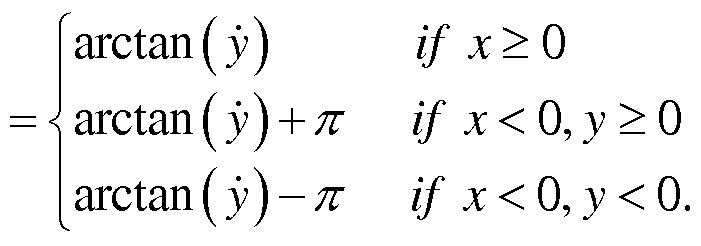
Priority Applications (2)
| Application Number | Priority Date | Filing Date | Title |
|---|---|---|---|
| CN201180023702.6A CN102985277B (en) | 2010-12-31 | 2011-05-12 | The intelligent traffic safety system and the decision-making technique thereof that detect based on comprehensive state |
| US13/674,836 US8841994B2 (en) | 2010-05-12 | 2012-11-12 | Intelligent traffic safety system based on comprehensive state detection and decision method thereof |
Applications Claiming Priority (14)
| Application Number | Priority Date | Filing Date | Title |
|---|---|---|---|
| CN2010201876960U CN201761368U (en) | 2010-05-12 | 2010-05-12 | Remote wireless monitoring system for alcoholic content of drivers |
| CN201020187696.0 | 2010-05-12 | ||
| CN201010620675.8A CN102097003B (en) | 2010-12-31 | 2010-12-31 | Intelligent traffic safety system and terminal |
| CN201020696275.0 | 2010-12-31 | ||
| CN201020696275 | 2010-12-31 | ||
| CN201020696640.8 | 2010-12-31 | ||
| CN2010206966408U CN201932117U (en) | 2010-12-31 | 2010-12-31 | Network system for preventing automobile burglaries and robberies based on pattern recognition |
| CN201010620675.8 | 2010-12-31 | ||
| CN201120149271.5 | 2011-05-11 | ||
| CN201120149259.4 | 2011-05-11 | ||
| CN2011201492594U CN202029653U (en) | 2011-05-11 | 2011-05-11 | Monitoring system for redundancy reliability of internal condition of automobile tire |
| CN2011201492715U CN202029843U (en) | 2011-05-11 | 2011-05-11 | Vehicle active anti-collision system based on microwave radar |
| CN201110122062.6 | 2011-05-12 | ||
| CN201110122062.6A CN102201035B (en) | 2011-05-12 | 2011-05-12 | A kind of predictor method calculating road ahead camber/gradient |
Related Child Applications (1)
| Application Number | Title | Priority Date | Filing Date |
|---|---|---|---|
| US13/674,836 Continuation US8841994B2 (en) | 2010-05-12 | 2012-11-12 | Intelligent traffic safety system based on comprehensive state detection and decision method thereof |
Publications (1)
| Publication Number | Publication Date |
|---|---|
| WO2011140993A1 true WO2011140993A1 (en) | 2011-11-17 |
Family
ID=44913961
Family Applications (1)
| Application Number | Title | Priority Date | Filing Date |
|---|---|---|---|
| PCT/CN2011/074013 Ceased WO2011140993A1 (en) | 2010-05-12 | 2011-05-12 | Intelligent traffic safety system based on comprehensive state detection and decision method thereof |
Country Status (2)
| Country | Link |
|---|---|
| US (1) | US8841994B2 (en) |
| WO (1) | WO2011140993A1 (en) |
Cited By (26)
| Publication number | Priority date | Publication date | Assignee | Title |
|---|---|---|---|---|
| CN105416230A (en) * | 2015-11-27 | 2016-03-23 | 山东科技大学 | Illegal vehicle capturing control system and method based on car networking |
| CN105761418A (en) * | 2016-05-10 | 2016-07-13 | 招商局重庆交通科研设计院有限公司 | Vehicle transport safety monitoring system based on Internet of Vehicles |
| CN106101641A (en) * | 2016-07-18 | 2016-11-09 | 中国科学院地理科学与资源研究所 | Video frequency monitoring system and monitoring method thereof |
| CN106467112A (en) * | 2016-10-11 | 2017-03-01 | 斑马信息科技有限公司 | Vehicle-mounted DAS (Driver Assistant System) |
| CN106671880A (en) * | 2016-12-30 | 2017-05-17 | 天津云视科技发展有限公司 | Vehicle operation state diagnostic system applying cloud computing and artificial intelligence technology |
| CN107452203A (en) * | 2017-09-07 | 2017-12-08 | 安徽芯核防务装备技术股份有限公司 | Bus is seted on fire early warning and monitoring platform |
| CN107688884A (en) * | 2016-08-04 | 2018-02-13 | 同方威视技术股份有限公司 | Safety check centralized management system |
| US10144349B2 (en) | 2014-12-26 | 2018-12-04 | The Yokohama Rubber Co., Ltd. | Collision avoidance system and collision avoidance method |
| CN109532670A (en) * | 2018-11-28 | 2019-03-29 | 广州市网拓信息技术有限公司 | A kind of on-vehicle safety Distance Judgment device extremely software uses principle |
| CN109961159A (en) * | 2019-03-07 | 2019-07-02 | 长安大学 | A new type of vehicle non-disintegration detection and network supervision method |
| CN110428620A (en) * | 2019-07-30 | 2019-11-08 | 江苏驭道数据科技有限公司 | A kind of driving risk behavior Data collecting and analysis system |
| CN110422117A (en) * | 2019-08-14 | 2019-11-08 | 天津清智科技有限公司 | A kind of vehicle drive environment monitoring method |
| CN110594472A (en) * | 2019-08-26 | 2019-12-20 | 浙江理工大学 | An Intelligent Electric Actuator for Flow Monitoring Valve |
| CN110597258A (en) * | 2019-09-19 | 2019-12-20 | 北京和绪科技有限公司 | Intelligent automobile automatic driving system |
| CN110689271A (en) * | 2019-10-02 | 2020-01-14 | 龙岩华崇信息科技有限公司 | Internet of things intelligent weighing integrated management platform and management method |
| CN110843764A (en) * | 2019-11-29 | 2020-02-28 | 长安大学 | A kind of assistance system that promotes the driver to drive safely |
| CN112071061A (en) * | 2020-09-11 | 2020-12-11 | 谢能丹 | Vehicle service system based on cloud computing and data analysis |
| CN112462360A (en) * | 2020-11-13 | 2021-03-09 | 珠海大横琴科技发展有限公司 | Monitoring method, monitoring device, electronic equipment and storage medium |
| CN112991757A (en) * | 2021-03-15 | 2021-06-18 | 四川爱通线缆股份有限公司 | Warning method for safe driving |
| CN113129587A (en) * | 2021-03-23 | 2021-07-16 | 江门职业技术学院 | Road abnormity monitoring method, monitoring device and computer readable storage medium |
| CN113850123A (en) * | 2021-08-18 | 2021-12-28 | 广州国交润万交通信息有限公司 | Video-based highway monitoring method and device, storage medium and monitoring system |
| US11325601B2 (en) * | 2017-05-15 | 2022-05-10 | Continental Automotive Gmbh | Method for producing a passing probability collection, method for operating a control device of a motor vehicle, passing probability collecting device and control device |
| CN114821108A (en) * | 2022-05-10 | 2022-07-29 | 扬州大学 | Intelligent trolley for detecting vital signs of poultry and cloud management method thereof |
| CN116229715A (en) * | 2023-02-13 | 2023-06-06 | 武汉理工大学 | Method and system for generating continuous flow in road weaving area |
| CN116476800A (en) * | 2023-06-26 | 2023-07-25 | 深圳万甲荣实业有限公司 | New energy vehicle power distribution control method based on multi-sensor data fusion |
| CN118658307A (en) * | 2024-08-20 | 2024-09-17 | 中路科云(北京)技术有限公司 | Intelligent early warning system and method for trunk road traffic safety based on edge computing |
Families Citing this family (91)
| Publication number | Priority date | Publication date | Assignee | Title |
|---|---|---|---|---|
| WO2007136745A2 (en) | 2006-05-19 | 2007-11-29 | University Of Hawaii | Motion tracking system for real time adaptive imaging and spectroscopy |
| US9606209B2 (en) | 2011-08-26 | 2017-03-28 | Kineticor, Inc. | Methods, systems, and devices for intra-scan motion correction |
| CN103247091B (en) * | 2012-02-07 | 2016-01-20 | 厦门金龙联合汽车工业有限公司 | A kind of driving evaluation system and method |
| US9037394B2 (en) * | 2012-05-22 | 2015-05-19 | Hartford Fire Insurance Company | System and method to determine an initial insurance policy benefit based on telematics data collected by a smartphone |
| US9341718B2 (en) * | 2012-09-07 | 2016-05-17 | Honeywell International Inc. | Method and system for providing integrity for hybrid attitude and true heading |
| US9305365B2 (en) | 2013-01-24 | 2016-04-05 | Kineticor, Inc. | Systems, devices, and methods for tracking moving targets |
| US10327708B2 (en) | 2013-01-24 | 2019-06-25 | Kineticor, Inc. | Systems, devices, and methods for tracking and compensating for patient motion during a medical imaging scan |
| US9717461B2 (en) | 2013-01-24 | 2017-08-01 | Kineticor, Inc. | Systems, devices, and methods for tracking and compensating for patient motion during a medical imaging scan |
| EP2950714A4 (en) | 2013-02-01 | 2017-08-16 | Kineticor, Inc. | Motion tracking system for real time adaptive motion compensation in biomedical imaging |
| US20140266739A1 (en) * | 2013-03-18 | 2014-09-18 | Digio2 International Co., Ltd. | Health monitoring and warning system |
| JP6080948B2 (en) * | 2013-04-26 | 2017-02-15 | 三菱電機株式会社 | In-vehicle device, navigation system, and facility information display method |
| ITRM20130274A1 (en) * | 2013-05-08 | 2014-11-09 | Smart I S R L | DISTRIBUTED AND INTELLIGENT OPTICAL SENSOR SYSTEM FOR ADAPTIVE, PREDICTIVE AND ON-DEMAND CONTROL OF PUBLIC LIGHTING |
| CN104276082A (en) * | 2013-07-05 | 2015-01-14 | 鸿富锦精密工业(深圳)有限公司 | Vehicle-mounted auxiliary device |
| DE102013214383A1 (en) * | 2013-07-23 | 2015-01-29 | Robert Bosch Gmbh | Method and device for providing a collision signal with regard to a vehicle collision, method and device for managing collision data regarding vehicle collisions, and method and device for controlling at least one collision protection device of a vehicle |
| US9403482B2 (en) | 2013-11-22 | 2016-08-02 | At&T Intellectual Property I, L.P. | Enhanced view for connected cars |
| GB2521665A (en) * | 2013-12-30 | 2015-07-01 | Nokia Technologies Oy | Method, apparatus, computer program and system for controlling a vehicle's alert output |
| US9475387B2 (en) * | 2014-03-16 | 2016-10-25 | Roger Li-Chung Wu | Drunk driving prevention system and method with eye symptom detector |
| WO2015148391A1 (en) | 2014-03-24 | 2015-10-01 | Thomas Michael Ernst | Systems, methods, and devices for removing prospective motion correction from medical imaging scans |
| EP3131076B1 (en) * | 2014-04-09 | 2018-12-19 | Technomirai Co., Ltd | Digital loss/accident defense system, method, and program |
| EP3188660A4 (en) | 2014-07-23 | 2018-05-16 | Kineticor, Inc. | Systems, devices, and methods for tracking and compensating for patient motion during a medical imaging scan |
| US9913607B2 (en) * | 2014-12-26 | 2018-03-13 | The Yokohama Rubber Co., Ltd. | Collision avoidance system and collision avoidance method |
| US9934443B2 (en) * | 2015-03-31 | 2018-04-03 | Daon Holdings Limited | Methods and systems for detecting head motion during an authentication transaction |
| US9610510B2 (en) * | 2015-07-21 | 2017-04-04 | Disney Enterprises, Inc. | Sensing and managing vehicle behavior based on occupant awareness |
| US9943247B2 (en) | 2015-07-28 | 2018-04-17 | The University Of Hawai'i | Systems, devices, and methods for detecting false movements for motion correction during a medical imaging scan |
| CN105243839B (en) * | 2015-09-18 | 2018-01-05 | 黑龙江大学 | Networking is used for the Multifunctional alcohol detector and information transferring method of traffic administration |
| EP3159235B1 (en) * | 2015-10-22 | 2021-08-04 | Honda Research Institute Europe GmbH | Method and system for assisting a driver of a vehicle in driving the vehicle and computer program |
| US9443426B1 (en) | 2015-11-13 | 2016-09-13 | Byron Paul Formwalt | Method and device for sensing traffic flow and notifying motor vehicle drivers of the same |
| CN108697367A (en) | 2015-11-23 | 2018-10-23 | 凯内蒂科尓股份有限公司 | Systems, devices and methods for patient motion to be tracked and compensated during medical image scan |
| CN105629953B (en) * | 2016-01-15 | 2018-12-18 | 深圳佑驾创新科技有限公司 | Body of rod identifying system based on vehicle assistant drive |
| CN105911266A (en) * | 2016-05-23 | 2016-08-31 | 南宁市茂百科技有限公司 | Multifunctional alcohol detector |
| CN105842433A (en) * | 2016-05-24 | 2016-08-10 | 南宁市茂百科技有限公司 | Intelligent alcohol strength tester |
| US10640117B2 (en) * | 2016-08-17 | 2020-05-05 | Allstate Insurance Company | Driving cues and coaching |
| JP2018055445A (en) * | 2016-09-29 | 2018-04-05 | 株式会社デンソー | Vehicle operation management system |
| US10214220B2 (en) | 2016-09-30 | 2019-02-26 | International Business Machines Corporation | Intelligent driving recommendation system |
| CN106428017A (en) * | 2016-10-11 | 2017-02-22 | 成都芯云时代科技有限公司 | Driver assistance system based on WiFi environment and big data |
| WO2018117631A1 (en) * | 2016-12-21 | 2018-06-28 | Samsung Electronics Co., Ltd. | Electronic apparatus and method of operating the same |
| US10150474B2 (en) * | 2017-01-04 | 2018-12-11 | Robert Bosch Gmbh | Reducing lateral position deviation during an automated lane change |
| EP3379222B1 (en) | 2017-03-22 | 2020-12-30 | Methode Electronics Malta Ltd. | Magnetoelastic based sensor assembly |
| CN109398084A (en) * | 2017-08-18 | 2019-03-01 | 江苏斯诺物联科技有限公司 | A kind of fatigue driving detecting system based on physiological driver's parameter |
| US10901423B2 (en) | 2017-09-01 | 2021-01-26 | International Business Machines Corporation | Generating driving behavior models |
| DE102017219066A1 (en) * | 2017-10-25 | 2019-04-25 | Bayerische Motoren Werke Aktiengesellschaft | Method for sensory recognition of a kidnapping situation, system and means of locomotion |
| WO2019122414A1 (en) | 2017-12-22 | 2019-06-27 | Resmed Sensor Technologies Limited | Apparatus, system, and method for physiological sensing in vehicles |
| WO2019122413A1 (en) | 2017-12-22 | 2019-06-27 | Resmed Sensor Technologies Limited | Apparatus, system, and method for motion sensing |
| KR102658390B1 (en) | 2017-12-22 | 2024-04-17 | 레스메드 센서 테크놀로지스 리미티드 | Devices, systems, and methods for health and medical sensing |
| JP6977569B2 (en) * | 2018-01-11 | 2021-12-08 | トヨタ自動車株式会社 | Driving support device and driving support method |
| JP6676084B2 (en) * | 2018-02-01 | 2020-04-08 | 株式会社Subaru | Vehicle occupant monitoring device |
| US11014417B2 (en) | 2018-02-27 | 2021-05-25 | Methode Electronics, Inc. | Towing systems and methods using magnetic field sensing |
| EP3758959B1 (en) | 2018-02-27 | 2025-11-05 | Methode Electronics, Inc. | Towing systems and methods using magnetic field sensing |
| US11491832B2 (en) | 2018-02-27 | 2022-11-08 | Methode Electronics, Inc. | Towing systems and methods using magnetic field sensing |
| US11221262B2 (en) | 2018-02-27 | 2022-01-11 | Methode Electronics, Inc. | Towing systems and methods using magnetic field sensing |
| US11135882B2 (en) | 2018-02-27 | 2021-10-05 | Methode Electronics, Inc. | Towing systems and methods using magnetic field sensing |
| US11084342B2 (en) | 2018-02-27 | 2021-08-10 | Methode Electronics, Inc. | Towing systems and methods using magnetic field sensing |
| US10538259B2 (en) * | 2018-03-28 | 2020-01-21 | Deuta America Corp | Fit-for-duty detection and alerting system for rail and transit |
| US10935974B1 (en) * | 2018-04-19 | 2021-03-02 | State Farm Mutual Automobile Insurance Company | Manual control re-engagement in an autonomous vehicle |
| CN110549943A (en) * | 2018-06-01 | 2019-12-10 | 新疆北方建设集团有限公司 | Detection device and on-vehicle detection device based on curb |
| CN109131050A (en) * | 2018-07-11 | 2019-01-04 | 上海思致汽车工程技术有限公司 | A kind of intelligent vehicle-tracing system, car searching method and intelligent automobile |
| CN109068291A (en) * | 2018-07-21 | 2018-12-21 | 芜湖英特杰智能科技有限公司 | A kind of emergency method of the vehicle traffic accident emergency system based on Zigbee module |
| CN109212989B (en) * | 2018-09-27 | 2023-09-05 | 北京理工大学 | A smart home storage device and control method based on indoor visible light positioning |
| CN109857109B (en) * | 2019-01-31 | 2020-12-29 | 大汉智能科技(广州)有限公司 | Highway route track positioning system for intelligent traffic |
| US11312293B2 (en) * | 2019-05-02 | 2022-04-26 | Tdisp Inc. | Display system for transportation networks |
| CN110119149A (en) * | 2019-05-15 | 2019-08-13 | 深圳市英博超算科技有限公司 | A kind of Vehicular automatic driving redundance Decision Control method and system |
| US12439003B2 (en) | 2019-12-23 | 2025-10-07 | Waymo Llc | Real-time adjustment of vehicle sensor field of view volume |
| CN113525374A (en) * | 2020-04-15 | 2021-10-22 | 罗伯特·博世有限公司 | Method for controlling vehicle, vehicle controller, and vehicle body stabilization system |
| CN111645678B (en) * | 2020-05-20 | 2022-10-21 | 吉林大学 | A vehicle braking and steering coordination control anti-collision system and control method |
| CN112477873B (en) * | 2020-12-15 | 2024-04-30 | 广东海洋大学 | An assisted driving and vehicle safety management system based on Internet of Vehicles |
| US12133730B2 (en) * | 2020-12-23 | 2024-11-05 | Qatar Foundation For Education, Science And Community Development | Systems and methods for evaluating mindfulness |
| CN113052997B (en) * | 2021-03-08 | 2023-05-26 | 青岛卡沃斯智能制造有限公司 | Intelligent robot system and method for escort of hazardous chemicals |
| CN112977321B (en) * | 2021-04-02 | 2025-03-25 | 中联重科股份有限公司 | Vehicle safety control system and method, mixer truck |
| CN113382384B (en) * | 2021-06-13 | 2022-08-02 | 西北工业大学 | Vehicle local networking oriented road region dividing method based on multi-source sensing technology |
| CN113859156B (en) * | 2021-09-28 | 2023-12-22 | 中国北方车辆研究所 | Redundant intelligent power distribution management system for unmanned vehicles |
| CN113895431B (en) * | 2021-09-30 | 2023-07-04 | 重庆电子工程职业学院 | Vehicle detection method and system |
| CN114103859A (en) * | 2021-10-20 | 2022-03-01 | 南京工程学院 | A kind of vehicle rear-end collision warning method and system |
| CN113815532B (en) * | 2021-11-11 | 2023-05-09 | 深圳市尖峰时刻电子有限公司 | Vehicle BSD blind area monitoring and warning system based on Internet of things |
| CN114148321B (en) * | 2021-11-22 | 2023-06-20 | 长安大学 | An automatic emergency braking and safety evaluation method considering collision risk |
| CN114912878A (en) * | 2022-06-07 | 2022-08-16 | 公安部第三研究所 | A vehicle transportation safety monitoring system based on driver holographic management |
| US12055398B2 (en) * | 2022-06-09 | 2024-08-06 | Here Global B.V. | Method and apparatus for predicting carjackings |
| CN115009286A (en) * | 2022-06-21 | 2022-09-06 | 北京理工大学 | Method and device for intelligently sensing and intervening driving fatigue |
| CN115123237A (en) * | 2022-06-24 | 2022-09-30 | 山东科技大学 | An easy-to-install intelligent lane-change assistance system |
| CN115123129B (en) * | 2022-07-01 | 2023-11-07 | 浙江极氪智能科技有限公司 | Driving safety guarantee method, device, equipment and storage medium |
| IT202300000384A1 (en) * | 2023-01-13 | 2024-07-13 | Sicura S R L | MONITORING AND MANAGEMENT SYSTEM FOR A COMPANY FLEET OF TRANSPORT VEHICLES |
| CN115805924B (en) * | 2023-01-28 | 2023-05-16 | 江苏钜熙矿用设备科技有限公司 | Mining vehicle braking control system |
| CN116176573B (en) * | 2023-03-14 | 2025-05-27 | 长安大学 | Energy loss-based rear vehicle danger identification avoidance system and method |
| CN116520856B (en) * | 2023-07-04 | 2023-09-22 | 交通运输部水运科学研究所 | Quantitative safety avoidance system for terminal transport vehicles based on IGV smart navigation |
| EP4425945A4 (en) | 2023-07-28 | 2024-11-06 | New Automobile Co., Ltd | Visual collection system provided in smart terminal of intelligent logistics vehicle |
| CN116668852B (en) * | 2023-07-28 | 2023-09-22 | 新汽有限公司 | A visual acquisition system equipped with intelligent terminals for smart logistics vehicles |
| CN117078687B (en) * | 2023-10-17 | 2023-12-15 | 常州海图信息科技股份有限公司 | Track inspection system and method based on machine vision |
| CN117995021B (en) * | 2024-04-07 | 2024-06-11 | 交通运输部公路科学研究所 | Vehicle safety warning method and system based on multi-source data fusion algorithm |
| CN118394049B (en) * | 2024-06-28 | 2024-11-08 | 广州通达汽车电气股份有限公司 | Method and system for realizing remote diagnosis and controlling vehicle |
| US12384403B1 (en) * | 2024-11-12 | 2025-08-12 | HAAS, Inc. | Systems and methods for intelligent vehicle- specific digital alerting |
| CN119935249A (en) * | 2025-04-07 | 2025-05-06 | 华南师范大学 | An abnormal warning system for intelligent transport vehicles |
| CN120343053B (en) * | 2025-04-29 | 2025-12-09 | 威海奥顿信息科技有限公司 | Internet of things equipment monitoring system and method based on big data |
Citations (5)
| Publication number | Priority date | Publication date | Assignee | Title |
|---|---|---|---|---|
| CN1706693A (en) * | 2004-06-12 | 2005-12-14 | 孟春晓 | Anti-collision safety system for automobile |
| CN101407193A (en) * | 2008-11-11 | 2009-04-15 | 徐克林 | Anticollision alarming device for vehicle |
| CN101480939A (en) * | 2008-12-10 | 2009-07-15 | 李进 | Remote monitoring theftproof system of vehicle |
| CN201325292Y (en) * | 2008-11-20 | 2009-10-14 | 奇瑞汽车股份有限公司 | Automobile tyre pressure monitor system based on wireless sensing device and CAN bus |
| CN201378052Y (en) * | 2009-01-21 | 2010-01-06 | 高德软件有限公司 | Gradient measuring system and road section information measuring device |
Family Cites Families (3)
| Publication number | Priority date | Publication date | Assignee | Title |
|---|---|---|---|---|
| JP4466571B2 (en) * | 2005-05-12 | 2010-05-26 | 株式会社デンソー | Driver status detection device, in-vehicle alarm device, driving support system |
| JP4645598B2 (en) * | 2006-05-23 | 2011-03-09 | 株式会社デンソー | Brake control device for vehicle |
| JP4848994B2 (en) * | 2006-12-22 | 2011-12-28 | 株式会社エクォス・リサーチ | Vehicle control device |
-
2011
- 2011-05-12 WO PCT/CN2011/074013 patent/WO2011140993A1/en not_active Ceased
-
2012
- 2012-11-12 US US13/674,836 patent/US8841994B2/en active Active
Patent Citations (5)
| Publication number | Priority date | Publication date | Assignee | Title |
|---|---|---|---|---|
| CN1706693A (en) * | 2004-06-12 | 2005-12-14 | 孟春晓 | Anti-collision safety system for automobile |
| CN101407193A (en) * | 2008-11-11 | 2009-04-15 | 徐克林 | Anticollision alarming device for vehicle |
| CN201325292Y (en) * | 2008-11-20 | 2009-10-14 | 奇瑞汽车股份有限公司 | Automobile tyre pressure monitor system based on wireless sensing device and CAN bus |
| CN101480939A (en) * | 2008-12-10 | 2009-07-15 | 李进 | Remote monitoring theftproof system of vehicle |
| CN201378052Y (en) * | 2009-01-21 | 2010-01-06 | 高德软件有限公司 | Gradient measuring system and road section information measuring device |
Cited By (32)
| Publication number | Priority date | Publication date | Assignee | Title |
|---|---|---|---|---|
| US10144349B2 (en) | 2014-12-26 | 2018-12-04 | The Yokohama Rubber Co., Ltd. | Collision avoidance system and collision avoidance method |
| CN105416230A (en) * | 2015-11-27 | 2016-03-23 | 山东科技大学 | Illegal vehicle capturing control system and method based on car networking |
| CN105761418A (en) * | 2016-05-10 | 2016-07-13 | 招商局重庆交通科研设计院有限公司 | Vehicle transport safety monitoring system based on Internet of Vehicles |
| CN106101641A (en) * | 2016-07-18 | 2016-11-09 | 中国科学院地理科学与资源研究所 | Video frequency monitoring system and monitoring method thereof |
| CN107688884A (en) * | 2016-08-04 | 2018-02-13 | 同方威视技术股份有限公司 | Safety check centralized management system |
| CN106467112A (en) * | 2016-10-11 | 2017-03-01 | 斑马信息科技有限公司 | Vehicle-mounted DAS (Driver Assistant System) |
| CN106671880A (en) * | 2016-12-30 | 2017-05-17 | 天津云视科技发展有限公司 | Vehicle operation state diagnostic system applying cloud computing and artificial intelligence technology |
| US11325601B2 (en) * | 2017-05-15 | 2022-05-10 | Continental Automotive Gmbh | Method for producing a passing probability collection, method for operating a control device of a motor vehicle, passing probability collecting device and control device |
| CN107452203A (en) * | 2017-09-07 | 2017-12-08 | 安徽芯核防务装备技术股份有限公司 | Bus is seted on fire early warning and monitoring platform |
| CN109532670A (en) * | 2018-11-28 | 2019-03-29 | 广州市网拓信息技术有限公司 | A kind of on-vehicle safety Distance Judgment device extremely software uses principle |
| CN109532670B (en) * | 2018-11-28 | 2022-02-22 | 广州市网拓信息技术有限公司 | Vehicle-mounted safe distance judgment device and software use principle thereof |
| CN109961159A (en) * | 2019-03-07 | 2019-07-02 | 长安大学 | A new type of vehicle non-disintegration detection and network supervision method |
| CN110428620A (en) * | 2019-07-30 | 2019-11-08 | 江苏驭道数据科技有限公司 | A kind of driving risk behavior Data collecting and analysis system |
| CN110422117A (en) * | 2019-08-14 | 2019-11-08 | 天津清智科技有限公司 | A kind of vehicle drive environment monitoring method |
| CN110594472A (en) * | 2019-08-26 | 2019-12-20 | 浙江理工大学 | An Intelligent Electric Actuator for Flow Monitoring Valve |
| CN110597258A (en) * | 2019-09-19 | 2019-12-20 | 北京和绪科技有限公司 | Intelligent automobile automatic driving system |
| CN110689271A (en) * | 2019-10-02 | 2020-01-14 | 龙岩华崇信息科技有限公司 | Internet of things intelligent weighing integrated management platform and management method |
| CN110689271B (en) * | 2019-10-02 | 2023-04-07 | 龙岩华崇信息科技有限公司 | Internet of things intelligent weighing integrated management platform and management method |
| CN110843764B (en) * | 2019-11-29 | 2021-06-22 | 长安大学 | A kind of assistance system that promotes the driver to drive safely |
| CN110843764A (en) * | 2019-11-29 | 2020-02-28 | 长安大学 | A kind of assistance system that promotes the driver to drive safely |
| CN112071061B (en) * | 2020-09-11 | 2021-10-15 | 武汉云上融媒科技有限公司 | Vehicle service system based on cloud computing and data analysis |
| CN112071061A (en) * | 2020-09-11 | 2020-12-11 | 谢能丹 | Vehicle service system based on cloud computing and data analysis |
| CN112462360A (en) * | 2020-11-13 | 2021-03-09 | 珠海大横琴科技发展有限公司 | Monitoring method, monitoring device, electronic equipment and storage medium |
| CN112991757A (en) * | 2021-03-15 | 2021-06-18 | 四川爱通线缆股份有限公司 | Warning method for safe driving |
| CN113129587A (en) * | 2021-03-23 | 2021-07-16 | 江门职业技术学院 | Road abnormity monitoring method, monitoring device and computer readable storage medium |
| CN113850123A (en) * | 2021-08-18 | 2021-12-28 | 广州国交润万交通信息有限公司 | Video-based highway monitoring method and device, storage medium and monitoring system |
| CN114821108A (en) * | 2022-05-10 | 2022-07-29 | 扬州大学 | Intelligent trolley for detecting vital signs of poultry and cloud management method thereof |
| CN116229715A (en) * | 2023-02-13 | 2023-06-06 | 武汉理工大学 | Method and system for generating continuous flow in road weaving area |
| CN116229715B (en) * | 2023-02-13 | 2024-01-12 | 武汉理工大学 | Continuous flow generation method and system for road interleaving area |
| CN116476800A (en) * | 2023-06-26 | 2023-07-25 | 深圳万甲荣实业有限公司 | New energy vehicle power distribution control method based on multi-sensor data fusion |
| CN116476800B (en) * | 2023-06-26 | 2023-08-15 | 深圳万甲荣实业有限公司 | New energy automobile power distribution control method based on multi-sensor data fusion |
| CN118658307A (en) * | 2024-08-20 | 2024-09-17 | 中路科云(北京)技术有限公司 | Intelligent early warning system and method for trunk road traffic safety based on edge computing |
Also Published As
| Publication number | Publication date |
|---|---|
| US20130069773A1 (en) | 2013-03-21 |
| US8841994B2 (en) | 2014-09-23 |
Similar Documents
| Publication | Publication Date | Title |
|---|---|---|
| WO2011140993A1 (en) | Intelligent traffic safety system based on comprehensive state detection and decision method thereof | |
| CN102985277B (en) | The intelligent traffic safety system and the decision-making technique thereof that detect based on comprehensive state | |
| CN102097003B (en) | Intelligent traffic safety system and terminal | |
| US11713060B2 (en) | Systems and methods for remote monitoring of a vehicle, robot or drone | |
| US12319277B2 (en) | Method and apparatus for controlling automated vehicle | |
| US10437249B2 (en) | Vehicle control apparatus | |
| CN102390320B (en) | Vehicle anti-collision early warning system based on vehicle-mounted sensing network | |
| CN101857008B (en) | Active-mode intelligent safety monitoring instrument for car | |
| CN114056346B (en) | Automatic driving control method and device | |
| CN104960466B (en) | A kind of automobile turning safety assisting system | |
| CN107878466A (en) | Wake alarm for the vehicle with autonomous mode | |
| CN101908272A (en) | Traffic safety perception network based on mobile information | |
| CN204978641U (en) | Car turn safety auxiliary device | |
| CN106114502A (en) | A kind of intelligent automobile aid system | |
| WO2022126485A1 (en) | Intelligent traffic management system based on traffic flow | |
| KR20180064639A (en) | Vehicle and control method thereof | |
| CN206049559U (en) | A kind of vehicle DAS (Driver Assistant System) based on computer technology | |
| CN114954307A (en) | Driving assistance system based on artificial intelligence | |
| CN206194136U (en) | Prevent driver fatigue device and prevent driver fatigue system | |
| CN111114561B (en) | Control method of tramcar auxiliary driving system based on ADAS technology | |
| CN108621932A (en) | A kind of vehicle early warning reminding method and device | |
| KR102658910B1 (en) | Driving practice system using autonomous vehicle | |
| CN113936468B (en) | Road corner early warning system and control method | |
| KR102658916B1 (en) | Safety support and extension system for self driving cars | |
| CN220500675U (en) | Intelligent vehicle defensive driving system in visual blind spot environment |
Legal Events
| Date | Code | Title | Description |
|---|---|---|---|
| WWE | Wipo information: entry into national phase |
Ref document number: 201180023702.6 Country of ref document: CN |
|
| 121 | Ep: the epo has been informed by wipo that ep was designated in this application |
Ref document number: 11780214 Country of ref document: EP Kind code of ref document: A1 |
|
| NENP | Non-entry into the national phase |
Ref country code: DE |
|
| 122 | Ep: pct application non-entry in european phase |
Ref document number: 11780214 Country of ref document: EP Kind code of ref document: A1 |