WO2011064989A1 - Radiographic imaging apparatus - Google Patents
Radiographic imaging apparatus Download PDFInfo
- Publication number
- WO2011064989A1 WO2011064989A1 PCT/JP2010/006848 JP2010006848W WO2011064989A1 WO 2011064989 A1 WO2011064989 A1 WO 2011064989A1 JP 2010006848 W JP2010006848 W JP 2010006848W WO 2011064989 A1 WO2011064989 A1 WO 2011064989A1
- Authority
- WO
- WIPO (PCT)
- Prior art keywords
- wireless transmission
- imaging apparatus
- radiographic imaging
- radiographic
- transmission unit
- Prior art date
- Legal status (The legal status is an assumption and is not a legal conclusion. Google has not performed a legal analysis and makes no representation as to the accuracy of the status listed.)
- Ceased
Links
Images


Classifications
-
- G—PHYSICS
- G03—PHOTOGRAPHY; CINEMATOGRAPHY; ANALOGOUS TECHNIQUES USING WAVES OTHER THAN OPTICAL WAVES; ELECTROGRAPHY; HOLOGRAPHY
- G03B—APPARATUS OR ARRANGEMENTS FOR TAKING PHOTOGRAPHS OR FOR PROJECTING OR VIEWING THEM; APPARATUS OR ARRANGEMENTS EMPLOYING ANALOGOUS TECHNIQUES USING WAVES OTHER THAN OPTICAL WAVES; ACCESSORIES THEREFOR
- G03B42/00—Obtaining records using waves other than optical waves; Visualisation of such records by using optical means
- G03B42/02—Obtaining records using waves other than optical waves; Visualisation of such records by using optical means using X-rays
- G03B42/04—Holders for X-ray films
Definitions
- the present invention relates to a radiographic imaging apparatus that detects radiation and acquires a radiographic image.
- Radiographic imaging apparatuses using flat panel sensors formed of thin-film semiconductor material on insulating substrates are being put to practical use as imaging apparatuses for medical image diagnosis and nondestructive testing by radiation.
- a radiographic imaging apparatuses using a flat panel sensor converts radiation that has been transmitted through a subject to be tested to an analog electrical signal at the flat panel sensor and acquires a digital image signal by carrying out analog-to-digital conversion.
- a digital radiographic imaging apparatus is used for picking up still images and moving images, such as fluoroscopic images.
- the housing of a digital radiographic imaging apparatus is a metal housing or a molded housing covered with an electromagnetic shield.
- the stiffness of the radiographic imaging apparatus is maintained, and the electronic circuits inside the radiographic imaging apparatus are protected from external electromagnetic noise.
- a decrease in image quality of the radiographic images will have an adverse effect on healthcare. Therefore, such a decrease in image quality of the radiographic images due to electromagnetic noise must be prevented.
- a wireless communication unit such as an antenna
- the housing blocks external electromagnetic waves. Therefore, an opening is formed in the housing near the wireless communication unit to ensure satisfactory wireless communication.
- a large opening will ensure satisfactory wireless communication.
- the large opening will cause a reduction in the stiffness of the radiographic imaging apparatus.
- the present invention has been made in consideration of the above situations and provides a radiographic imaging apparatus that ensures optimal wireless communication while maintaining the stiffness of the radiographic imaging apparatus.
- the present invention provides a radiographic imaging apparatus including a radiographic-image detecting unit configured to detect radiation and convert the detected radiation to an image signal; a wireless transmission unit configured to wirelessly transmit the image signal to an external device; and a housing configured to cover the radiographic-image detecting unit and the wireless transmission unit, wherein a first side surface of the housing has a first opening for wireless transmission performed by the wireless transmission unit, and a second side surface of the housing adjoining the first side surface has a second opening for wireless transmission by the wireless transmission unit.
- Fig. 1 is a sectional side view of an electronic cassette according to a first embodiment.
- Fig. 2A illustrates a schematic arrangement of antenna covers according to the first embodiment.
- Fig. 2B illustrates a schematic arrangement of antenna covers according to the first embodiment.
- Fig. 2C illustrates a schematic arrangement of antenna covers according to the first embodiment.
- Fig. 2D illustrates a schematic arrangement of antenna covers according to the first embodiment.
- Fig. 2E illustrates a schematic arrangement of antenna covers according to the first embodiment.
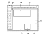
- Fig. 3 is a sectional top view of an electronic cassette according to a second embodiment.
- Fig. 4 is a sectional side view of the electronic cassette according to the second embodiment.
- Fig. 5 is a sectional top view of an electronic cassette according to a third embodiment.
- Figs. 1 and 2A to 2E illustrate the configuration of a radiographic imaging apparatus according to this embodiment.
- the radiographic imaging apparatus according to this embodiment will be described with reference to Figs. 1 and 2A to 2E.
- Fig. 1 is a sectional side view of an electronic cassette according to this embodiment. As illustrated in Fig. 1, the electronic cassette according to this embodiment is shaped as a cuboid.
- a housing 101 of an electronic cassette 10 includes a stiff metal housing part 101b and a radiation incident surface formed of a high radiation-transmittance material 101a.
- the housing 101 accommodates a radiographic image sensor 102 that functions as a radiographic image detecting unit detecting radiation and converting the detected radiation to an image signal.
- a sensor retaining plate 107 is attached to the radiographic image sensor 102 on the surface opposite to the radiation incident surface of the radiographic image sensor 102.
- the sensor retaining plate 107 and the radiographic image sensor 102 are joined together with a radiation shielding plate 108 interposed therebetween so as to protect electric substrates, including a control circuit portion 104, and prevent image degradation due to backscattering.
- the radiographic image sensor 102 a plurality of pixels, each having a converter element converting the radiation to a charge corresponding to the radiation and a switching element transferring an electrical signal based on the charge, are arranged two-dimensionally.
- the radiographic image sensor 102 is connected to a readout circuit portion 106 that reads out electrical signals from the pixels via a flexible circuit board 105.
- the readout circuit portion 106 and the control circuit portion 104 that controls electrical signals are connected via a cable (not shown).
- a wireless transmission and reception antenna 103 functions as a wireless receiving unit and a wireless transmitting unit transmitting image signals to and from external devices. Instead of the wireless transmission and reception antenna 103, a wireless transmission antenna mainly for transmitting image signals may be used.
- the wireless transmission and reception antenna 103 is connected to the control circuit portion 104 via a cable (not shown).
- the wireless transmission and reception antenna 103 be a protrusion on the housing 101 that is covered with a non-conductive cover.
- the wireless transmission and reception antenna 103 is disposed on the side opposite to the side on which the radiation incident surface of the radiographic image sensor 102 is disposed. In this way, size of the electronic cassette 10 becomes substantially the same as that of a film cassette.
- antenna covers 11 and 12 including non-conductive members are disposed on adjoining surfaces of the housing 101 near the wireless transmission and reception antenna 103.
- the antenna covers 11 and 12 of the housing 101 are installed in openings, each having a length larger than one half of wavelength l of the antenna frequency F.
- the wireless transmission and reception antenna 103 is a multiband antenna
- openings each having a length larger than one half of the longest wavelength should be formed.
- optimal wireless transmission is achieved by forming a first opening in a first side surface of the housing 101 and forming a second opening in a second side surface adjoining the first side surface.
- the stiffness of the housing 101 is maintained by forming the antenna openings such that an edge section 101c shared by two surfaces of the housing 101 is left.
- the radiating property of the antenna and the stiffness of the housing 101 are ensured, and the size of the device (the size compatible with the size of the cassette).
- the antenna covers 11 and 12 are light-shielding members and prevent the radiographic image sensor 102 from being exposed to external light.
- Figs. 2A to 2E illustrate example arrangements of the antenna covers of this embodiment.
- the antenna covers 11 and 12 are disposed on a side surface of the electronic cassette 10 and the surface opposing the radiation incident surface.
- the antenna covers 11 and 12 are provided as an integrated structure such that the antenna covers 11 and 12 can be removed from the electronic cassette 10 together with the edge section 101 as one piece. By provided the antenna covers as an integrated structure, the number of components can be reduced.
- antenna covers 11 and 12 are disposed separately on a side surface of the electronic cassette 10 and the surface opposing the radiation incident surface.
- stiffness is increased, and the size can be decreased (especially, the thickness of the housing and frame can be reduced).
- antenna covers 12 and 13 are disposed separately on two adjoining side surfaces near a corner of the electronic cassette 10.
- the stiffness of the corner sections is lowered but an optimal antenna radiating property can be acquired when, for example, a metal structure is installed behind the electronic cassette 10.
- antenna covers 12, 13, and 14 are disposed separately on two adjoining side surfaces and on the surface opposing the radiation incident surface near a corner of the electronic cassette 10.
- the stiffness is lowered and the size is large (in particular, the frame is thick) but the antenna radiating property is optimal, providing a structure effective in environments with unsatisfactory wireless communication conditions.
- antenna covers 11 and 12 are disposed on a side surface of the electronic cassette 10 and the surface opposing the radiation incident surface.
- an antenna cover 13 is disposed on another side surface on which the antenna cover 12 is not disposed, and an antenna 14 is provided on the surface opposing the radiation incident surface.
- the antenna property is improved even more by providing two antennas, each of which has the same structure as the antenna illustrated in Fig. 2B. Any of the arrangements in Figs. 2A, 2B, and 2C can be combined; for example, the arrangements in Figs. 2B and 2C may be combined.
- the width of the edge sections of the housing differ depending on the arrangement, when there is no restrictions on the external size of the housing, the width of the edge sections are set to a value that ensures resistance against impacts, such as drops.
- antenna cover parts such as those illustrated in Fig. 2B, are also provided in the arrangements illustrated in Figs. 2C, 2D, and 2E.
- the antenna cover parts may instead be integrated such as those illustrated in Fig. 2A.
- Figs. 3 and 4 illustrate the internal structure of a radiographic imaging apparatus according to this embodiment.
- the radiographic imaging apparatus according to this embodiment will be described with reference to Figs. 3 and 4.
- Fig. 3 is a sectional top view from the back side of the radiation incident surface of an electronic cassette 200 according to this embodiment.
- Fig. 4 is a sectional side view of the electronic cassette 200 according to this embodiment.
- the housing of the electronic cassette 200 accompanies a radiographic image sensor 201 and a sensor retaining plate 211, which are joined together with a radiation-shielding and noise-shielding metal shielding plate 210 interposed therebetween.
- a radiographic image sensor 201 a plurality of pixels, each having a converter element converting radiation to a charge corresponding to the radiation and a switching element transferring an electrical signal based on the charge, are arranged two-dimensionally.
- a driving circuit portion 203 outputs a driving signal having a voltage that makes the switching element conductive to the switching element via a flexible circuit board.
- the driving circuit portion 203 and a readout circuit portion 202 that reads out electrical signals from the pixels are respectively connected to a first side and a second side different from the first side of the radiographic image sensor 201.
- the readout circuit portion 202 is covered with a metal shield portion 206 that prevents a reduction in image quality due to noise.
- the readout circuit portion 202 and a control circuit portion 204 that controls the electrical signal are connected via a cable (not shown).
- a wireless communication unit 205 is disposed near a side opposing the readout circuit portion 202 so that the radiating property is not degraded and/or the resonant frequency is not changed due to the influence of surrounding conductive members.
- the periphery is covered with a non-conductive material (not shown). The influence of noise can be reduced by disposing the wireless communication unit 205 on the surface opposite to the radiation incident surface of the radiographic image sensor 201 with the radiation-shielding and noise shielding metal shielding plate 210.
- the radiographic imaging apparatus also includes a power source 208 supplying power to the radiographic image sensor 201 and the circuit boards.
- the power source 208 together with the wireless communication unit 205, enables wireless communication.
- all components are disposed on the surface opposing the radiation incident surface of the radiographic image sensor 201.
- an apparatus that does not require a size reduction may have the components disposed on a surface not opposing the radiation incident surface of the radiographic image sensor 201.
- an electronic cassette accommodates a double-scanning radiation sensor having two readout circuit portions, which enable high-speed readout and are disposed at two opposing sides.
- a wireless communication unit cannot be disposed at a side opposing the readout circuit portion.
- Fig. 5 is a sectional top view from the back side of the radiation incident surface of the electronic cassette according to this embodiment.
- Readout circuit portions 202a and 202b that readout electrical signals from pixels are connected to opposing sides of a radiographic image sensor 201.
- a driving circuit portion 203 is connected to a third side.
Landscapes
- Physics & Mathematics (AREA)
- General Physics & Mathematics (AREA)
- Measurement Of Radiation (AREA)
- Apparatus For Radiation Diagnosis (AREA)
- Radiography Using Non-Light Waves (AREA)
Abstract
Description
Claims (8)
- A radiographic imaging apparatus comprising:
a radiographic-image detecting unit configured to detect radiation and convert the detected radiation to an image signal;
a wireless transmission unit configured to wirelessly transmit the image signal to an external device; and
a housing configured to cover the radiographic-image detecting unit and the wireless transmission unit,
wherein a first side surface of the housing has a first opening for wireless transmission performed by the wireless transmission unit, and a second side surface of the housing adjoining the first side surface has a second opening for wireless transmission by the wireless transmission unit. - The radiographic imaging apparatus according to Claim 1, wherein a first non-conductive member is disposed in the first opening, and a second non-conductive member is disposed in the second opening.
- The radiographic imaging apparatus according to Claim 2, wherein the first non-conductive member and the second non-conductive member have a light blocking effect.
- The radiographic imaging apparatus according to Claim 1, wherein the first non-conductive member and the second non-conductive material are provided as an integrated structure.
- The radiographic imaging apparatus according to Claim 1, wherein the wireless transmission unit is a wireless transmission antenna.
- The radiographic imaging apparatus according to Claim 1, further comprising:
a readout circuit disposed at a first side inside the radiographic imaging apparatus and configured to readout the image signal from the radiographic-image detecting unit,
wherein the radiographic imaging apparatus is shaped as a cuboid, and
wherein the wireless transmission unit is disposed at a second side different from the first side inside the radiographic imaging apparatus. - The radiographic imaging apparatus according to Claim 1, further comprising:
a shielding plate interposed between the radiographic-image detecting unit and the wireless transmission unit and configured to prevent an influence of noise. - The radiographic imaging apparatus according to Claim 6, wherein the wireless transmission unit is disposed at the center of the second side.
Priority Applications (2)
| Application Number | Priority Date | Filing Date | Title |
|---|---|---|---|
| US13/508,858 US8822937B2 (en) | 2009-11-27 | 2010-11-24 | Radiographic imaging apparatus |
| CN201080053824.5A CN102630309B (en) | 2009-11-27 | 2010-11-24 | Radiographic imaging apparatus |
Applications Claiming Priority (2)
| Application Number | Priority Date | Filing Date | Title |
|---|---|---|---|
| JP2009-270096 | 2009-11-27 | ||
| JP2009270096A JP5451341B2 (en) | 2009-11-27 | 2009-11-27 | Radiation imaging equipment |
Publications (1)
| Publication Number | Publication Date |
|---|---|
| WO2011064989A1 true WO2011064989A1 (en) | 2011-06-03 |
Family
ID=43626940
Family Applications (1)
| Application Number | Title | Priority Date | Filing Date |
|---|---|---|---|
| PCT/JP2010/006848 Ceased WO2011064989A1 (en) | 2009-11-27 | 2010-11-24 | Radiographic imaging apparatus |
Country Status (4)
| Country | Link |
|---|---|
| US (1) | US8822937B2 (en) |
| JP (1) | JP5451341B2 (en) |
| CN (1) | CN102630309B (en) |
| WO (1) | WO2011064989A1 (en) |
Families Citing this family (21)
| Publication number | Priority date | Publication date | Assignee | Title |
|---|---|---|---|---|
| JP6227227B2 (en) * | 2012-05-31 | 2017-11-08 | コニカミノルタ株式会社 | Radiation imaging equipment |
| JP6050201B2 (en) * | 2013-09-09 | 2016-12-21 | 富士フイルム株式会社 | Electronic cassette |
| CN104688255A (en) * | 2013-12-09 | 2015-06-10 | 通用电气公司 | Optical detector, X-ray detection device, and computerized tomography device |
| JP6673435B2 (en) * | 2014-04-09 | 2020-03-25 | コニカミノルタ株式会社 | Radiation imaging equipment |
| JP6259382B2 (en) | 2014-09-22 | 2018-01-10 | 富士フイルム株式会社 | Electronic cassette |
| WO2016133178A1 (en) * | 2015-02-18 | 2016-08-25 | Canon Kabushiki Kaisha | Wireless communication device and electronic apparatus |
| JP6512857B2 (en) * | 2015-02-18 | 2019-05-15 | キヤノン株式会社 | Wireless communication device and electronic device |
| JP6512856B2 (en) * | 2015-02-18 | 2019-05-15 | キヤノン株式会社 | Wireless communication device and electronic device |
| JP6553929B2 (en) * | 2015-04-13 | 2019-07-31 | キヤノン株式会社 | Radiation imaging apparatus and imaging system |
| US10631801B2 (en) * | 2016-11-17 | 2020-04-28 | General Electric Company | Scintillator sealing for solid state X-ray detector |
| JP7043305B2 (en) * | 2018-03-20 | 2022-03-29 | キヤノン株式会社 | Radiography equipment and radiography system |
| JP7054356B2 (en) | 2018-03-20 | 2022-04-13 | キヤノン株式会社 | Radiation imaging device |
| JP7230256B2 (en) * | 2018-03-20 | 2023-02-28 | キヤノン株式会社 | radiography equipment |
| US10955571B2 (en) * | 2018-03-20 | 2021-03-23 | Canon Kabushiki Kaisha | Radiographing apparatus and radiographing system |
| JP6762994B2 (en) * | 2018-07-31 | 2020-09-30 | キヤノン株式会社 | Radiation imaging device |
| JP7631027B2 (en) * | 2021-03-01 | 2025-02-18 | キヤノン株式会社 | Radiation imaging apparatus, data processing apparatus, radiation imaging system, and method for controlling radiation imaging system |
| JP2023009367A (en) * | 2021-07-07 | 2023-01-20 | キヤノン株式会社 | Radiographic apparatus |
| CN115590539A (en) | 2021-07-07 | 2023-01-13 | 佳能株式会社(Jp) | radiographic imaging device |
| JP2023086028A (en) | 2021-12-09 | 2023-06-21 | キヤノン株式会社 | Radiation detector |
| JP7482100B2 (en) * | 2021-12-09 | 2024-05-13 | キヤノン株式会社 | Radiation detection equipment |
| US12260056B2 (en) * | 2023-02-06 | 2025-03-25 | Htc Corporation | Device and method for detection |
Citations (6)
| Publication number | Priority date | Publication date | Assignee | Title |
|---|---|---|---|---|
| JP2003210444A (en) * | 2002-01-23 | 2003-07-29 | Canon Inc | Radiation imaging equipment |
| US20070272873A1 (en) * | 2006-05-26 | 2007-11-29 | Eastman Kodak Company | Compact and durable encasement for a digital radiography detector |
| US7482595B1 (en) * | 2006-03-31 | 2009-01-27 | General Electric Company | Digital radiography detector assembly with access opening |
| US20090026376A1 (en) * | 2007-07-23 | 2009-01-29 | Takeshi Kuwabara | Cassette device and cassette storage bag for cassette device |
| WO2009054231A1 (en) * | 2007-10-25 | 2009-04-30 | Konica Minolta Medical & Graphic, Inc. | Cassette-type radiation image solid detector |
| JP2009270096A (en) | 2008-04-11 | 2009-11-19 | Kuraray Co Ltd | Method of hydrogenating polymer, and hydrogenated polymer obtained by hydrogenation reaction |
Family Cites Families (4)
| Publication number | Priority date | Publication date | Assignee | Title |
|---|---|---|---|---|
| US7203549B2 (en) * | 2003-10-02 | 2007-04-10 | Medtronic, Inc. | Medical device programmer with internal antenna and display |
| JP2009048171A (en) * | 2007-07-23 | 2009-03-05 | Fujifilm Corp | Cassette device and cassette storage bag provided in the cassette device |
| JP4444348B2 (en) | 2007-08-16 | 2010-03-31 | 富士フイルム株式会社 | Radiation detection cassette and radiographic imaging system |
| JP5073519B2 (en) * | 2008-01-30 | 2012-11-14 | 富士フイルム株式会社 | Electronics |
-
2009
- 2009-11-27 JP JP2009270096A patent/JP5451341B2/en active Active
-
2010
- 2010-11-24 CN CN201080053824.5A patent/CN102630309B/en active Active
- 2010-11-24 WO PCT/JP2010/006848 patent/WO2011064989A1/en not_active Ceased
- 2010-11-24 US US13/508,858 patent/US8822937B2/en active Active
Patent Citations (7)
| Publication number | Priority date | Publication date | Assignee | Title |
|---|---|---|---|---|
| JP2003210444A (en) * | 2002-01-23 | 2003-07-29 | Canon Inc | Radiation imaging equipment |
| JP3990914B2 (en) | 2002-01-23 | 2007-10-17 | キヤノン株式会社 | Radiation imaging equipment |
| US7482595B1 (en) * | 2006-03-31 | 2009-01-27 | General Electric Company | Digital radiography detector assembly with access opening |
| US20070272873A1 (en) * | 2006-05-26 | 2007-11-29 | Eastman Kodak Company | Compact and durable encasement for a digital radiography detector |
| US20090026376A1 (en) * | 2007-07-23 | 2009-01-29 | Takeshi Kuwabara | Cassette device and cassette storage bag for cassette device |
| WO2009054231A1 (en) * | 2007-10-25 | 2009-04-30 | Konica Minolta Medical & Graphic, Inc. | Cassette-type radiation image solid detector |
| JP2009270096A (en) | 2008-04-11 | 2009-11-19 | Kuraray Co Ltd | Method of hydrogenating polymer, and hydrogenated polymer obtained by hydrogenation reaction |
Also Published As
| Publication number | Publication date |
|---|---|
| CN102630309B (en) | 2014-12-24 |
| JP2011112923A (en) | 2011-06-09 |
| US8822937B2 (en) | 2014-09-02 |
| JP5451341B2 (en) | 2014-03-26 |
| CN102630309A (en) | 2012-08-08 |
| US20120228499A1 (en) | 2012-09-13 |
Similar Documents
| Publication | Publication Date | Title |
|---|---|---|
| US8822937B2 (en) | Radiographic imaging apparatus | |
| JP5743477B2 (en) | Radiography equipment | |
| US10061042B2 (en) | Radiation imaging apparatus and radiation imaging system | |
| US10283839B2 (en) | Dual band SRR loaded cavity antenna | |
| KR101927690B1 (en) | Radiation imaging system | |
| US11320546B2 (en) | Radiation imaging apparatus | |
| JP2010127680A (en) | Radiographic image detecting sensor unit | |
| JP2010127882A (en) | Radiological image detecting device | |
| JP7635450B2 (en) | Radiation imaging system and radiation imaging apparatus | |
| JP2011045213A (en) | Cassette charging device | |
| JP7043305B2 (en) | Radiography equipment and radiography system | |
| JP5709972B2 (en) | Radiation imaging equipment | |
| EP4014071B1 (en) | Radiographic detector | |
| JP2018004520A (en) | Radiation image photographing device | |
| US12265187B2 (en) | Radiation detection apparatus | |
| JP2022111805A (en) | Radiographic device |
Legal Events
| Date | Code | Title | Description |
|---|---|---|---|
| WWE | Wipo information: entry into national phase |
Ref document number: 201080053824.5 Country of ref document: CN |
|
| 121 | Ep: the epo has been informed by wipo that ep was designated in this application |
Ref document number: 10796160 Country of ref document: EP Kind code of ref document: A1 |
|
| WWE | Wipo information: entry into national phase |
Ref document number: 13508858 Country of ref document: US |
|
| NENP | Non-entry into the national phase |
Ref country code: DE |
|
| 122 | Ep: pct application non-entry in european phase |
Ref document number: 10796160 Country of ref document: EP Kind code of ref document: A1 |