WO2011026257A1 - System and method for analyzing gait by fabric sensors - Google Patents
System and method for analyzing gait by fabric sensors Download PDFInfo
- Publication number
- WO2011026257A1 WO2011026257A1 PCT/CN2009/000999 CN2009000999W WO2011026257A1 WO 2011026257 A1 WO2011026257 A1 WO 2011026257A1 CN 2009000999 W CN2009000999 W CN 2009000999W WO 2011026257 A1 WO2011026257 A1 WO 2011026257A1
- Authority
- WO
- WIPO (PCT)
- Prior art keywords
- gait analysis
- sensor according
- fabric
- sensor
- gait
- Prior art date
- Legal status (The legal status is an assumption and is not a legal conclusion. Google has not performed a legal analysis and makes no representation as to the accuracy of the status listed.)
- Ceased
Links
Classifications
-
- A—HUMAN NECESSITIES
- A61—MEDICAL OR VETERINARY SCIENCE; HYGIENE
- A61B—DIAGNOSIS; SURGERY; IDENTIFICATION
- A61B5/00—Measuring for diagnostic purposes; Identification of persons
- A61B5/103—Measuring devices for testing the shape, pattern, colour, size or movement of the body or parts thereof, for diagnostic purposes
- A61B5/1036—Measuring load distribution, e.g. podologic studies
- A61B5/1038—Measuring plantar pressure during gait
-
- A—HUMAN NECESSITIES
- A61—MEDICAL OR VETERINARY SCIENCE; HYGIENE
- A61B—DIAGNOSIS; SURGERY; IDENTIFICATION
- A61B5/00—Measuring for diagnostic purposes; Identification of persons
- A61B5/68—Arrangements of detecting, measuring or recording means, e.g. sensors, in relation to patient
- A61B5/6801—Arrangements of detecting, measuring or recording means, e.g. sensors, in relation to patient specially adapted to be attached to or worn on the body surface
- A61B5/6802—Sensor mounted on worn items
- A61B5/6804—Garments; Clothes
- A61B5/6807—Footwear
-
- A—HUMAN NECESSITIES
- A61—MEDICAL OR VETERINARY SCIENCE; HYGIENE
- A61B—DIAGNOSIS; SURGERY; IDENTIFICATION
- A61B5/00—Measuring for diagnostic purposes; Identification of persons
- A61B5/103—Measuring devices for testing the shape, pattern, colour, size or movement of the body or parts thereof, for diagnostic purposes
- A61B5/11—Measuring movement of the entire body or parts thereof, e.g. head or hand tremor or mobility of a limb
- A61B5/112—Gait analysis
Definitions
- the invention can be applied to the fields of rehabilitation therapy, physical training, long-term care, orthopedics and sports medicine, health care, entertainment and the like.
- SUMMARY OF THE INVENTION The present invention is directed to sensing a walking motion of a wearer using a fabric sensor attached to the garment, and performing an analysis to know the physiological condition of the wearer. Background technique
- Gait analysis is often used to help athletes, as well as patients with impaired motor function, such as cerebral palsy, Parkinson's disease, stroke or accidental injuries.
- gait analysis is often performed in a specialized laboratory or physician's office, and must be accomplished using a number of sophisticated devices and complex methods.
- the most ideal gait analysis system should be able to be continuously monitored, low cost, easy to operate, and easy to obtain.
- the prior art also has a disadvantage: it does not exhibit the motor function of the subject in normal life. Therefore, both experts and patients need a low-cost system that can produce quantified and reproducible results.
- Most of the current gait analysis is used to help athletes and injured people, mainly in the laboratory, or in the doctor's office and visual observation.
- US6231527 is equipped with a camera and shoes as a gait analysis sensor, and when performing gait analysis, it can only be performed indoors, allowing users to perform gait analysis indoors, thereby causing users Inconvenient operation is not conducive to the promotion of gait analysis systems.
- US Patent No. US6984208 uses ultrasonic waves to test the user's posture and movement state and gait analysis related data, but it is not conducive to the popularity of gait analysis related systems due to the cost of acquiring ultrasonic related equipment.
- US 2008010891 3A 1 uses a pressure sensor to detect a user's gait analysis, but still needs to have an independent power supply on each shoe or sock and is not a digital sensor, and at the same time, in signal processing Need feedback method (Feedback)
- Needback Need feedback method
- the process is too cumbersome, lengthy, and complex. It requires the use of neuro-fuzzy theory. It is difficult to synchronize the gait changes of the tester in real time.
- US Patent No. US20090012433A1 requires a camera, a microphone, and a sensor to detect the user's gait analysis related data, but this analysis method is too cumbersome, which is not conducive to the promotion of gait analysis.
- US Patent No. US2007 / 0112287 A1 uses an accelerometer and a gyroscope to hang on the ear to detect the user's gait analysis related data, which is not comfortable to use. Summary of the invention
- the gait sensor can connect a sense of physiology. Detectors, such as heartbeat, breathing, body temperature, sweat, blood oxygen, electrocardiogram and other sensors, can sense physiological functions during limb movement, allowing the invention to be further extended to every level of daily life, and measured
- the gait analysis of the user in various postures is performed to analyze the physiological state of the user. Previously, the sensor was placed on the shoe and did not directly match the foot. The resulting gait analysis error was extremely large and could not be matched in various shoes, which was too expensive and consumes electricity.
- the invention is provided with the sensor on the sock, which is comfortable and washable on the one hand, and can measure the data of the gait analysis when the user wears different shoes, and is suitable for the users of all levels, because The size required for the socks is not as precise as the shoes, but the socks can fit snugly on the user's feet, so the resulting gait analysis can be more precise.
- the sock sensor can also know that when the user is walking, the user wears different shoes, and the gait analysis signal can be used to know the style of the shoe that the user is currently wearing. Such as: high heels, flat shoes, slippers, sports shoes, skates, etc.
- the sock sensor of the invention can be arranged on different shoes, and is easy to use and ergonomic for the user. As long as the user wears the sock sensor, it can be applied to various shoes, so that the growth time can be integrated. Continuous exercise physiology and gait analysis changes are very helpful for the health and safety of users. Moreover, since the present invention is to mount a sensor in one or more everyday clothes that are in contact with the body, it is advantageous for the promotion and application of the present invention.
- One of the objects of the present invention is to use clothes and pants in addition to the sensors on the socks.
- measure gait analysis and attitude changes such as the angle of knee flexion, the length of the step, the number of steps per minute and the walking speed, or whether the heel is stepping on the ground, whether the arm is swinging, whether the waist is bent, and using
- the order of the posture changes, the period and other parameters, to observe the health of the user's limbs or rehabilitation treatment, or to determine the user's posture can also be used as an input to interactive computer games, rather than virtual games that are now only on the computer, because the players themselves have no actual action to interact with the game software.
- the invention is a wearable gait analysis system, which has the following features: 1. It is wearable, comfortable and can be directly installed on general pants or socks for use in real life; 2. The wearable type The gait analysis system has the following features: washable, durable, reliable, flexible, and inexpensive, so it can be easily applied to every level of daily life; 3. Use common digital output interfaces, such as: Bluetooth, The measured data can be directly transmitted to the instruments commonly used in daily life for signal analysis, such as: PDA or laptop.
- these easy-to-obtain electronic instruments can be used to test the user's posture and gait analysis data, and can also predict the next action to generate and evaluate gait or behavioral abnormalities, and the variability and stability of each parameter. The degree can also be clearly expressed in the Power Spectrum.
- Figure 1 is a block diagram of a gait analysis system utilizing a fabric sensor of the present invention.
- Fig. 2 is a view showing the sensor architecture of the first embodiment of the gait analysis system using the fabric sensor of the present invention.
- Figure 3A is a sensor position map on the sock.
- Figure 3B is a schematic illustration of the relative position of the sensor on the sock.
- Figure 4A is a sensor position map on the knee joint.
- Fig. 4B is a schematic view showing the position of the tension sensor mounted on the pants.
- Figure 5 is a typical gait timing diagram and sensor position.
- Figure 6 is the first four phases of the phase of ga i t analysis of the gait.
- Figure 7 is the post three phase of the phase of the gait (pha s e of ga i t) analysis.
- Figure 8A is a completed gait analysis diagram.
- Figure 8B is a flow chart of the method of the phase of the gait.
- Figure 9 is a schematic diagram for analysis of time parameters (Tempora l Parameters).
- Figure 10A is a pressure center analysis diagram of a normal walk.
- Figure 1 0B is a quality center analysis diagram of normal walking.
- Figure 10C is an analysis of the pressure center and mass center of the upper floor.
- Figure 10D is an analysis of the pressure center and center of the running.
- Figure 1 0E is an analysis of the pressure center and mass center of the lower building.
- Figure 1 OF is the full pressure analysis of the first jump and then jump.
- Figure 1 0G is an analysis of the posture state of the first jump and then jump.
- Figure 1 0H is the full motion quality analysis diagram of the first jump and then jump.
- Figure 1 1 is a timing diagram of the running gait.
- Figure 12 is a timing diagram of the forward walking gait.
- Figure 1 3 is a timing diagram of the reverse gait.
- Figure 14 is a timing diagram of the gait upstairs.
- Figure 15 is a timing diagram of the gait of the lower building.
- Figure 16 is a schematic illustration of a first sock sensing system.
- Figure 17 is a schematic illustration of a second sock sensing system.
- Figure 18 is a schematic illustration of a third sock sensing system.
- Figure 19A is a circuit diagram of a resistor mounted in parallel next to the sensor.
- Fig. 19B is a circuit diagram of a resistor mounted in series next to the sensor.
- Figure 20 is a timing diagram of the Cavaliers walking.
- Figure 21 is a timing diagram of a rider riding a bicycle.
- Figure 22 is a schematic illustration of a pressure sensor outputted in multiple stages.
- Figure 23 is a schematic illustration of the time difference between the two sensors on the heel to observe the inner and outer touchdown.
- Fig. 24A is a timing chart for traverse to the left.
- Fig. 24B is a timing chart for traversing to the right.
- Figure 25 is a timing chart of the kick step.
- Figure 26 is a timing chart of sitting down after going forward.
- Figure 27 is a timing chart of the fall after the advancement.
- Figure 28 is a schematic diagram of estimating the walking speed using the time difference of the sensor.
- Figure 29 is a timing chart of the treadmill (speed setting is 2km/hr).
- 30A and 30B are schematic diagrams of detection.
- Figure 31 is a flow chart of gait analysis.
- 32A and 32B are schematic diagrams of posture discrimination. The best way to achieve your invention
- the system architecture of the present invention is shown in the system architecture diagram.
- switches, pressure, gravity or tension sensors are installed on the socks or pants depending on the application (refer to PCT/CN2008/001570, PCT/CN2005/001520, PCT/ CN2008/001571 patent application), the above sensor is a Available in elastic materials such as: metal (eg iron), non-metallic (eg rubber, silicone, foam) and conductive carbon (eg graphite).
- metal eg iron
- non-metallic eg rubber, silicone, foam
- conductive carbon eg graphite
- other elastic materials can be added to the fabric during the manufacturing process (eg rubber, foam, silicone, sponge, spring, cotton, elastic fiber).
- the fabric sensor can be connected to a physiological sensor, such that when the wearer moves, the fabric sensor is reacted by an external force, and the physiological sensor simultaneously senses the wearer's physiological signal, especially when the wearer moves
- the physiological sensor is used to sense the physiological signal of the wearer to detect the state of the user.
- Microcontrollers can also be used to connect camera accelerometers or gyroscopes, camera accelerometers or gyroscopes to clothing, shoes, socks, control boxes or cell phones to increase the correctness of sensing limb movements.
- the present invention installs four digital sensors under the socks of the soles of the feet.
- the output is logically "1". " becomes “0", as shown in Figure 3, the sensor position map on the sock, Figure 3 is the position map relative to the sole of the foot, where (12) is the sole of the foot, (11) is the side of the foot, and (10) is the tibia. (9) is the part of the thumb of the foot.
- two tension sensors on the upper part of the trousers of the trousers respectively switching their output logic state at about 45 and 60 degrees, as shown in Figure 4 ⁇ , Figure 4 is the tension.
- FIG. 5 A schematic representation of the sensor on the trousers.
- the timing diagrams of the digital sensor output logic states are as shown in FIG. 5, wherein the sensors 1 to 4 are tension sensors, and the sensors 5 to 12 are pressure sensors.
- the first step of the two legs is the sensor 3 (45 degrees to the right knee), which changes from “0" to "1".
- the right leg is starting to rise, so the four sensors on the right foot start successively.
- Off-ground sensors 12 to 9 change from logic "0" to " ⁇ ”
- the sensors on the left foot are landed one after the other (sensors 8 to 5 are changed from logic "1" to "0").
- the present invention can obtain the gait timing diagram of FIG. 5, and the following diagram can be used to perform the following analysis.
- the gait timing is divided into seven phases, with the right heel touches the ground as the starting point, followed by the load response.
- the invention can be completed with the digital sensors of the toes and heels of the feet (sensor 5, 8 , 9, 12), as shown in Figure 6, take (a) and (f) for the right heel touch (initial contact), (b) for the left toe off the ground, (c) for the right heel off the ground, (d) The left heel touches the ground, (e) touches the ground with the left toe.
- the latter three phases are referred to as the swing phase.
- the invention can be accomplished with four pull digital sensors on the knees of the legs (sensors 1, 2, 3, 4), as shown in Fig. 7. .
- the initial swing should start from the right foot off the ground (g) to the right knee's most bend point (h).
- the right knee 60 degree pull force digital sensor sensor 4
- the intermediate point (h, ) whose output is "1" is replaced. Therefore, from sensors 1, 2, 3, 4, we can measure (g) to (h, ) for initial swing, (h,) to (i) for mid-swing.
- the microcontroller reads the logic state of each sensor at a sampling frequency of 100 times per second, that is, a sufficiently high time resolution can measure the time occupied by each stage of the gait, wherein all the gaits
- a sufficiently high time resolution can measure the time occupied by each stage of the gait, wherein all the gaits
- the recording time is the pre-swing period, and then the timer is reset to zero; then the right knee is 60 degrees, the tension sensor output is the intermediate point of 1, the recording time is the initial swing, and then the timer is reset to zero and then started;
- the pull sensor output changes from 1 to 0, and the recording time is the midpoint of the swing. After the timer is reset to zero, it is started;
- the phase periods of each step of the same person may be more or less different.
- the invention can continuously record the phase periods of each step in a few minutes, obtain the average value and standard deviation of each parameter, and also know the average value and standard deviation of the two-leg support, the standing period, the swing period. If the standard deviation of a person is too large, it means that the person may have an injury to the motor function. This is an important indicator, and the present invention can be completed at a low cost and with a simple operation.
- the microcontroller can also predict the next gait by this gait change data. If the two gaits change greatly, it means that the user's balance is poor, or the road is uneven, for example, on a treadmill. Or on the suspension bridge, or the leg is injured or the shoes are not fit. Under normal circumstances, the gait of the left and right feet should be periodic, otherwise it may be a fall or other sudden situation, and the present invention can raise an alarm.
- the number of steps is measured by the timing chart, as shown in Fig. 9.
- the gait timing diagram clearly illustrates the sequence of each sensor switch, but for analysts who want to analyze a large amount of gait information, the timing diagram is not easy to navigate. Therefore, the present invention specifically defines a pressure center (Centra l of pressure, COP) and a center of mass analysis method, so that analysts can quickly and easily analyze a large amount of gait information.
- the timing diagram generated by the two-legged digital sensor is shown in Figure 10A, where (a) shows that the left foot is everywhere ⁇ 3 ⁇ 4 ⁇ and the right foot is off the ground, and then (b) shows that the left foot is halfway away from the toes. Touching the ground with the foot, then (c) more than (b) one of the right ankle bone touches the ground.
- the change of the pressure center shows the stability of a person's walking gait. For example: Even if the user does not move on both feet, The pressure center still changes with time, so it can be known The sense of balance and the ability of the brain to control the feet.
- the number of sensors touching the ground of the left foot is defined as positive, and the number of sensors touching the ground of the right foot is defined as negative, and the sum of the two can be approximated to represent the person, and the center of mass of the body is left or biased.
- the present invention defines a total pressure (tot a l pressure) posture state (pos ture s ta te), and total motion quality (tota l movement mas s) analysis method, as follows:
- Posture state The sensor on the left side of the body is set to be positive when it is changed by an external force, and the sensor on the right side is set to be negative when it is changed by an external force, and the posture state is the sum of all the sensors;
- the value is zero, the time from 0 in the figure is the total time to jump to the ground, but the analysis chart formed by the center of mass (com) cannot be distinguished; then in the posture state analysis diagram 10G, we can see almost Both are at "0", and we set the value to 6 , which means that the subject is kneeling and ready to jump, so the process of jumping up first straightens the knee joint, then lifts the heel, then the toes are off the ground, so The value is zero. In this process, it can be seen that the knees of the legs are the time taken by the full motion quality analysis graph "6", so each parameter can express different posture states.
- Figure 10C shows the pressure and mass center analysis of the running and can be seen from the figure, a to h is the time point of the gait analysis of the upper floor; a point is the signal of the right foot just stepping on the ladder of the upper floor, It is also the starting point of this analysis definition, and the vertical line drawn from this time point can be It is clear that the knee of the right foot is bent more than 60 degrees at this point in time, while the left knee is barely bent; b is the signal that the left foot just left the ground, and the left foot has just bent more than 45 degrees.
- c time is the signal that the left knee flexion is just greater than 60 degrees.
- the right knee is still greater than 60 degrees, but the right knee is currently in a state of returning from a large angle to a small angle.
- d time point is the time point when the right foot knee has just returned to a small angle.
- the e point is the signal when the left heel just stepped on the step. At this time, the left foot knee angle is greater than 60 degrees, and the right foot knee is still less than 45 degrees.
- point f is the signal when the right heel has been off the ground and the knee just bends more than 60 degrees
- g point is the signal of the whole foot off the ground
- h point is the signal that the right foot just stepped on the ladder upstairs It is also the end point of this analysis definition.
- a cyclic analysis action of a complete upstairs gait can be known.
- the entire analysis paradigm is based on the right foot for analysis.
- the time from point a to point b is the time when the first foot supports the body; the time from point b to point e is the time when the right foot supports the body alone; the time from point e to point g is the second time that the feet support the body.
- Time; g to h time is the time when the right foot swings in the air.
- Figure 1 0D shows the pressure ⁇ ⁇ center analysis of the lower floor, and it can be seen from the figure that a to e is the time point of the running gait analysis; a point is the right heel just stepped on the ground
- the signal which is also the starting point for this analysis definition, can be clearly seen from the vertical line drawn at that point in time, the knee of the right foot is less than 45 degrees, and the left foot is completely suspended, while the left foot is knee It is just bent more than 60 degrees; b is the signal that the right toe has just left the ground. At this time, the right knee has just bent more than 60 degrees, while the left knee is still at 60 degrees, but is about to recover to less than 45 degrees.
- the state of c is that the left heel has just stepped onto the ground, and the left knee is more than 45 degrees less than 60 degrees, the right knee is still greater than 60 degrees, and the time difference between point b and point c is It is the time when the feet are still in the air, because there will be a movement similar to a small jump when running; d is the time point when the left toe is about to leave the ground, the left knee just bends more than 60 degrees while the right knee is still Then at a 60 degree angle, To return to the state is in a less than 45 degrees, e signal point is right heel just stepped on the ground, but also defined the end of this analysis. At this time, the knee angle of the right foot is less than 45 degrees, and the left knee is still at a state greater than 60 degrees, and the time difference between the point d and the point e is the time when the feet are still in the air.
- a to f are the time points of the gait analysis of the downstairs; point a is the signal that the right toe has just stepped on the stairs downstairs, and is also the starting point of this analysis definition, from this point of time
- the vertical line drawn can clearly see that the knee bending angle of the right foot is less than 45 degrees at this time point, while the left foot knee is bent more than 60 degrees; b point is the signal that the right heel has just stepped into the lower stairs, right now The knees of the feet are still less than 45 degrees, and the knees of the left foot are still more than 60 degrees.
- the c point is the signal that the left toes are off the stairs. The right knees are just bent more than 60 degrees, but the right foot is still on the stairs.
- the time point is the time when the left toe has just stepped into the stairs downstairs.
- the left knee is less than 45 degrees
- the right knee is greater than 60 degrees
- the e point is the signal when the right toe just leaves the lower stairs.
- the knee angle is greater than 60 degrees
- the left knee is still less than 45 degrees
- the f point is just the right toe.
- the signal to the stairs downstairs is also the end point of this analysis definition.
- the simplified running gait is shown in Figure 1.
- the standing period (A) is reduced and the swing period (B) is increased, and the time (C) at which the legs touch the ground at the same time is very short, in Figure 1.
- I can hardly see it in 1.
- the clothes on the arm have sensors, the user's exercise physiology can be further analyzed. Under normal circumstances, the greater the swing of the hand, the faster the movement of the foot and the synchronization of the two, generally the left hand and the right foot are synchronized. The right hand is synchronized with the left foot.
- the elbow joint is more curved, which can be used to assist the gait analysis and the accuracy of the exercise physiology. It is easier to judge the user's posture change.
- the simplified reverse gait is shown in Figure 13.
- the phase change is reversed compared to normal walking.
- the simplified upstairs gait is shown in Figure 14. It is significantly different from normal walking. For example, when the left leg is starting to go upstairs, the left knee is bent more than 45 degrees instead of straight (please refer to point (a) in Figure 14). ), this is to go up the stairs.
- the right foot touches the next step is the heel (Fig. 13 (b)), and the same right knee bends more than 45 degrees.
- the time difference between the heel and the thumb landing is small, the two are almost at the same time, and the knee is bent about twice as long as walking on the flat.
- Figure 15 is the signal that the right foot just stepped on the next step at the end of the swing period, not the heel. First, while the left knee is bent more than 45 degrees, the left foot is in contact with the next step and the toe (b) first touches the ground.
- the "60" generated by the knee 60-degree sensor was longer than the "1" generated in the behavior of going back and forth on the flat ground, so when the knee bend was greater than 45.
- the time spent is greater than the level walking, the user is going up or down the stairs or going up and down.
- the threshold value of the knee sensor is larger, the inclination of the up and down building or the up and down slope that can be detected is more easily detected without misjudgment, for example, 60 degrees response is 45 degrees.
- the length of the reaction time is the same.
- the slope of the up and down slope or the upper and lower floors will have the same time when the 60 degree sensor indicates that it is more inclined than the 45 degree sensor. If the 75 degree sensor is on the knee, You can get higher response to the up and down stairs or up and down slope changes.
- the present invention can identify the user as being walking, reversing, going up or down by checking A and B in the following table. Stairs, of course, the principle of up and down slopes is the same as that of the upper and lower floors, so the ground can be evaluated by the signal measured by the sensor.
- Table 1 Logic status table for walking, retreating, going up or down stairs
- the present invention can mount more sensors on pants or socks or clothing to improve the accuracy of recognition. For example, if two sensors are installed on the hips of the pants, the sensors of the two-leg socks are “1", and the sensors of the two pants are “1", and the hip sensor is also "1". " , that means the user is sitting, and the height of the chair is greater than the length of the leg, causing the legs to hang without touching the ground. Because in the summer, the user wears shorts, the sensor of the fixed knee joint is replaced by a sensor in the thigh area or a trousers in the joint (hitj on it) sensor to replace the sensor.
- Wireless communication such as RFID or video
- a microprocessor such as a controller or mobile phone on the clothes
- the external monitoring system using wireless transmission.
- the sensor formed by the socks and the shoes can also be multi-stage.
- the socks have a semi-spherical conductive material, and the two sets of conductive wires bl, b2 are concentric on the inner lining of the corresponding shoes.
- the distance between the wires of bl is less than the distance between the wires of b2, so when the hind legs are pressed down, first the conductive material of al, such as conductive sand or conductive metal sheet, first turns on the wires at both ends of bl, when the heel continues down.
- the multi-section pressure sensor composed of two separate conductive wires to form the conductive hemispheres of the socks with a separate bl, b2 for more accurate analysis, as shown in Figure 18, using the variable on the shoes.
- the electric group or the piezoelectric material or the variable capacitor cl replaces bl, b2.
- the variable electric group cl is placed on the inside of the shoe and one end corresponds to the center position of the ball of the al hemisphere of the sock.
- each sensor gets an analog signal.
- we separate the original sock sensor, some of which are in the shoes, such as the underline of the shoe and the bottom of the sock; or the sock camera speed gauge or the gyroscope To detect the acceleration and angular velocity of the action, to help me to detect the information more accurately.
- the walking is usually the heel first, so the heel signal will appear first than the toe.
- the back is usually the tip of the toe first, so the toe signal must appear earlier than the heel signal.
- the foot Before the foot signal of the foot appears, the foot will have a signal that the knee bends more than 60 degrees.
- the knee signal of the foot will be less than 45 degrees.
- a physiological sensor such as heartbeat, body temperature, sweat, blood oxygen, electrocardiogram, blood pressure, and respiration can be attached to the clothing to connect with the fabric sensor, and the physiological function can also be sensed.
- the present invention uses a flexible and washable stainless steel wire connection sensor and a microcontroller, that is, a stainless steel wire as a transmission line, a sock or a garment trouser as a circuit board.
- the stainless steel wire and the microcontroller are connected by a common snap or mother-and-pin buckle on the garment. Considering the comfort of the clothes, the stainless steel wire and the snaps or the mother and child buckles on the clothes should not be too much. If it is necessary to install a plurality of sensors in practical applications, the present invention can install a resistor beside each fabric sensor with a resistance ratio of 2, and then in series (Fig. 19B) or in parallel (Fig. 19A).
- the equivalent resistance of the four sensors can be 0, R, 2 R, 3R, 4R, 5R ... up to 1 5R, a total of 16 values, so It can guarantee that regardless of how the fabric sensors are switched, the equivalent resistances formed in series or in parallel are different, which can be resolved by the microcontroller after analog-to-digital conversion (a na 1 og- digi 1 conver si on) Logic of each fabric sensor State. This can greatly reduce the wire and snap or mother and child buckle.
- the present invention can also be applied to a bicycle rider to calculate the pedal pedal number, using the tire radius R, and stepping into a 2 ⁇ ⁇ to estimate the moving distance and speed because of the time used. It is known by the processor.
- the invention is applied to a bicycle knight, which is equipped with a 40- and 90-degree digital sensor on both knee joints, and the timing chart obtained by the rider and the bicycle is shown in Fig. 20 and Fig. 21, respectively, and right 1 and The left 1 is a 40 degree angle sensor, and the right 2 and left 2 are 90 degree angle sensors. Since the knee joint does not bend more than 90 degrees when walking, the 90-degree digital sensors on both knees in Figure 20 are all "0", and only the 40-degree digital sensor switches.
- both knees have at least 40 degrees of bending, so the 40-degree digital sensors on both knees in Figure 21 are both "0", only 90 degrees in the digital sensor switch, because when riding, The sole of the foot is still on the pedal of the bicycle, so it is in the state of turning on "0". Therefore, it is only necessary to use the sensor of the knee and set it at 90 degrees to react, so that it is possible to take or ride separately. Because the foot of the foot produces a knee signal _ ⁇ socks signal in the case of double ⁇ only bicycle riding. Therefore, the user's behavior status can also be distinguished. : When walking or riding a bicycle, the road condition necessarily affects the gait.
- the present invention uses a camera, an accelerometer or a gyroscope to measure the road condition and improves the accuracy of the gait recognition. For example, when a bicycle passes through a pothole or when a person suddenly falls, the accelerometer or gyroscope will get considerable acceleration (for example, above a gravitational acceleration) or an angle change, and the camera will also take a sharp change in the image. At this time, the microcontroller can Suspend the recognition of the gait to avoid false positives and record road conditions.
- a digital sensor can have three stages of output if needed, see Figure 22.
- the center of the digital sensor is a ball embedded in a ring-shaped conductive rubber or silica gel with a conductor under the cross, but no conductor in the middle.
- the lowest annular conductive rubber in the ball touches the lower conductor, but the higher annular conductive rubber in the ball does not touch the lower conductor, so only one set of conductors conducts; when the ball is heavily pressed, Two annular conductive rubbers in the ball will touch the lower conductor, so there are two sets of conductors conducting.
- the weight is heavier, the three groups on the ball are all connected. Therefore, in the gait analysis, the same point as the heel is not only "0".
- the result of "1" there may be different pressure or force performance, for example, when the pressure is greater than 20 kg, the first group of the ball is turned on, and when the gravity is greater than 40 kg, the two groups of the ball are turned on, greater than 60 When the force of kilograms is reached, the three groups of the ball are all connected, which can show the analysis result of the gait.
- the performance of the pressure center (COP) is more meaningful.
- the pressure change can be exhibited at each point of FIG. 10A, for example, 0 when there is no external force, 1 for the pressure at 20 to 40 kg, and 40 for the pressure.
- the weight is 2, and when the pressure is greater than 60 kg, the weight is 3, and the value presented at the heel has 4 variations instead of "0" or "1".
- the Quality Center (COM) is even more meaningful, because the meaning of the center of mass (COM) or pressure center (COP) is not just the change in the sole of the subject when looking at gait analysis, but also the difference in the sole of the foot. Point in the gait cycle The situation of pressure changes. Therefore, when performing mass center (COM), total pressure (tota l pressure), posture state (pos ture ta te), and total motion quality (tota l movement mas s) analysis, each point is weighted (for example, pressure In 40 to 60 kg, the weight is 2).
- More than two digital sensors can be mounted on the heel to distinguish the inside or outside of the foot when the foot is touched (except the inner eight or the outer eight feet), as shown in Figure 23.
- the digital sensor of the two heels of the same foot has a time difference of less than a small range. If the two feet are too different, it may be caused by a foot injury or a lesion. The reason is that more sensors can be placed in the socks, and the gait analysis result we detected is not a straight line signal, but the performance of the overall foot gait analysis of the left and right feet as a solid plane.
- the present invention can be implemented in a computer game in which the body interacts, and the body movements are input to the computer to increase the fun of the player.
- the signal of the arm and the body is presented by the top.
- Some gaits that rarely occur in daily life can occur in the game, such as going left or right, see Figure 24A, Figure 24B.
- the four sensors on both feet touch the ground almost at the same time; for example, kicking See Figure 25. There are few bends on the knees, but the four sensors on the feet are almost; for example, sitting down, see Figure 26, bending both knees; for example, falling, common in old people or children, see Figure 27, feet four The sensors touch the ground at the same time.
- the system can analyze the behavior patterns of users or animals; if there is danger, it can issue a warning.
- you can add camera acceleration gauges or gyroscopes to your clothes, socks, shoes, control boxes, or mobile phones to increase the power of the game's analog power to compensate for the lack of digital sensing while at the same time.
- State analysis or exercise physiology can also increase accuracy.
- the present invention considers the normal human condition and summarizes the following rules in order to pre-process the signals output by the respective sensors.
- the procedure for pre-processing each sensor signal of the present invention is as follows:
- the invention can use the time difference between the heel and the toe to touch the ground to estimate the speed of walking and obtain an approximate value.
- digital sensors S2 and S1 are installed on the heel and toe.
- the distance between the two sensors is a certain value d.
- the user can record the time difference of at least two speeds on the treadmill at a constant speed, approaching by interpolation in practical applications, or using a camera accelerometer or gyroscope to assist in correcting the accuracy.
- a timing diagram (Fig. 29) of a user walking on a treadmill (speed setting 2km/hr) as an example, the time difference between the two sensors S1 and S2 at the first to sixth steps is 0.32, 0.50.
- Fig. 30B it is assumed that the foot is in a constant-speed circular motion between the heel touch and the toe touch ground, and in the normal walking condition, the heel touches the ground instantaneously, the sole of the foot is at an angle to the ground (10 degrees), and S1 and S2 are sensed.
- the time difference between the grounding and the grounding time is At, and the grounding gradient is ⁇ *( ⁇ - At' ) / ⁇ 1 0
- the same principle can be obtained from at least two angle sensors at the joint, and the angular velocity of the joint can be known.
- the angular acceleration can be obtained by using the value of this and the next angular velocity and the time difference.
- the present invention can estimate the slope of the upslope or ups and downs of stairs by using the length of time the knee joint sensor is pulled apart, and obtain an approximate value.
- the steeper the slope the higher the leg must be lifted, the more the knee joint is bent, and the longer the knee sensor is pulled apart.
- a multi-segment sensor on the trousers for example: 45 degrees, 60 degrees, 75 degrees three segments, when the knee joint is straight from the beginning, only the 45 degree sensor has produced ' ⁇ ', and the next 45 degrees and 60 degrees sensor are generated", if Even if the 75-degree sensor is "", it means that the angle of the knee is larger, which means that the steeper the slope.
- Fig. 31 the flow of the gait analysis, we know that the heel of the foot is also the first when the user advances, but if the ground is uphill, the time difference between the heel strike time and the toe landing time becomes shorter. Conversely, if it is downhill, the forefoot will land first and the downhill angle will be larger. The pressure distribution on the toe and the heel will be opposite, ie the pressure will move to the toes, which is like wearing high heels. If it is added to the posture change of the upper body, as shown in Figure 31, where A stands for, when the user's posture changes, the sensor also responds at the same time, and is received by the information provided by the various sensors.
- B stands for providing a database to compare the on/off related signals on or off to determine the user's posture change;
- the 3D stereoscopic information of the posture change made by the user at the same time can more accurately detect the change of the posture of the subject, and can also know the posture state of the person at that time, for example, Table 2.
- the 8-bit string in the database from right to left represents right ⁇ , right elbow, left ⁇ , left elbow, right hip, right knee, left hip, left knee.
Landscapes
- Health & Medical Sciences (AREA)
- Life Sciences & Earth Sciences (AREA)
- Biomedical Technology (AREA)
- Molecular Biology (AREA)
- Veterinary Medicine (AREA)
- Biophysics (AREA)
- Pathology (AREA)
- Engineering & Computer Science (AREA)
- Public Health (AREA)
- Heart & Thoracic Surgery (AREA)
- Medical Informatics (AREA)
- Physics & Mathematics (AREA)
- Surgery (AREA)
- Animal Behavior & Ethology (AREA)
- General Health & Medical Sciences (AREA)
- Dentistry (AREA)
- Oral & Maxillofacial Surgery (AREA)
- Measurement Of The Respiration, Hearing Ability, Form, And Blood Characteristics Of Living Organisms (AREA)
- Measurement Of Distances Traversed On The Ground (AREA)
Abstract
Description
利用织品感测器的步态分析系统及方法 技术领域 Gait analysis system and method using fabric sensor
本发明可应用于复健治疗、 体能训练、 长期照护、 骨科及运动医学、 保 健、 娱乐等领域。 本发明是关于利用固定在衣物上的织品感测器, 来感测 穿戴者的步行动作, 并且进行分析, 以得知穿戴者的运动生理状况。 背景技术 The invention can be applied to the fields of rehabilitation therapy, physical training, long-term care, orthopedics and sports medicine, health care, entertainment and the like. SUMMARY OF THE INVENTION The present invention is directed to sensing a walking motion of a wearer using a fabric sensor attached to the garment, and performing an analysis to know the physiological condition of the wearer. Background technique
步态分析常用于帮助运动员, 以及运动功能受损的病患, 例如脑性淋 痹、 帕金森氏症、 中风或意外伤害的病患。 以现有技术, 步态分析常在专 业的实验室或医师的诊疗室下进行, 且必须利用许多精密的装置和复杂的 方法才能完成。 然而,最理想的步态分析系统, 应该是能即时连续监视、 低 成本、 易于操作、 且易于获得。 现有技术还有一缺点:它不能表现出受测者 在曰常生活中的运动功能。 故而,专家和病患都需要一套低成本的系统,能 获得量化且有再现性的结果。 目前步态分析大部分是用于帮助运动员和受 伤的人, 它主要是在实验室进行, 或在医生的办公室与目视观测。 临床医 生依靠广泛的步态分析、 诊断和治疗方法, 但都面临众多复杂的因素。 适 合一般使用者的步态分析系统和程序应具备随时监控、 价格低廉, 让消费 者易于使用, 并且容易取得。 然而, 传统的步态分析设备通常是需要实地 测试, 或者是在实验室做全面且健全的步态分析实验, 进而让步态分析系 统不利于普及。 Gait analysis is often used to help athletes, as well as patients with impaired motor function, such as cerebral palsy, Parkinson's disease, stroke or accidental injuries. In the prior art, gait analysis is often performed in a specialized laboratory or physician's office, and must be accomplished using a number of sophisticated devices and complex methods. However, the most ideal gait analysis system should be able to be continuously monitored, low cost, easy to operate, and easy to obtain. The prior art also has a disadvantage: it does not exhibit the motor function of the subject in normal life. Therefore, both experts and patients need a low-cost system that can produce quantified and reproducible results. Most of the current gait analysis is used to help athletes and injured people, mainly in the laboratory, or in the doctor's office and visual observation. Clinicians rely on extensive gait analysis, diagnosis, and treatment, but they all face many complex factors. Gait analysis systems and procedures for general users should be readily monitored and inexpensive, making them easy to use and easy to obtain. However, traditional gait analysis equipment usually requires field testing or a comprehensive and robust gait analysis experiment in the laboratory, which makes the gait analysis system unfavorable.
由于步态分析的门槛过高, 所以此时价格低廉的设备, 且能够及时提 供大量和可重复读取的数据, 并可长时间监测使用者的步态信号, 尤其是 对受过伤的使用者与帕金森氏症的病患, 都能产生极大的助益。 然而, 目 前步态分析相关的设备取得门槛高不可攀, 或是其相关的产品本身应用上 的限制, 并没有办法满足消费者的需求, 如: 美国专利号 US6789331 和 US7168185 ,其专利内容均是利用鞋子来当作步态分析感应器,且无法水洗, 从而造成使用者的不便。 美国专利号 US6231527 系搭配一台摄 几来和鞋 子做为步态分析感应器, 且进行步态分析时, 只能在室内进行, 让使用者 只能在室内从事步态分析, 进而造成使用者操作不便, 不利于步态分析系 统的推广。 美国专利号 US6984208 是利用超音波来测试使用者的姿势和移 动状态及步态分析相关数据, 但由于取得超音波的相关设备所费不赀, 故 不利于步态分析相关系统的普及。 美国专利号 US 2008010891 3A 1则用压力 感测器来侦测使用者的步态分析, 但仍需要在各个鞋子或袜子上设有一个 独立的电源且不是数字感测器, 同时,在信号处理需用反馈方法(Feedback) 来进行信号分析, 其过程过于繁瑣、 冗长、 复杂, 需要用到类神经及模糊 理论(neuro- fuzzy),若要即时同步表现出测试者的步态变化,会很困难。 美 国专利号 US20090012433A1 ,则是需要摄像机、麦克风,并搭配一感应器来侦 测使用者的步态分析相关数据, 但此分析方法过于麻烦, 不利于步态分析 的推广。 美国专利号 US200610282021. A 1,则是利用一感应器和一远端监视 系统来侦测使用者的姿势及步态分析相关数据,但此系统有距离的限制 ,当 使用者距离监视器较远时, 监视器就无法处理相关讯息。 美囯专利号 US2007 / 0112287 A1则是用加速规及陀螺仪来挂在耳朵上, 来侦测使用者的 步态分析相关数据, 在使用上并不舒适。 发明内容 Because the threshold of gait analysis is too high, the equipment with low price at this time can provide a large amount of data that can be read repeatedly and can monitor the gait signal of the user for a long time, especially for the injured user. Both patients with Parkinson's disease can be of great help. However, the current gait analysis related equipment has high barriers to entry, or the limitations of its related products, and there is no way to meet the needs of consumers, such as: US Patent Nos. US6789331 and US7168185, the patent contents are The shoe is used as a gait analysis sensor and cannot be washed, which causes inconvenience to the user. US Patent No. US6231527 is equipped with a camera and shoes as a gait analysis sensor, and when performing gait analysis, it can only be performed indoors, allowing users to perform gait analysis indoors, thereby causing users Inconvenient operation is not conducive to the promotion of gait analysis systems. US Patent No. US6984208 uses ultrasonic waves to test the user's posture and movement state and gait analysis related data, but it is not conducive to the popularity of gait analysis related systems due to the cost of acquiring ultrasonic related equipment. U.S. Patent No. US 2008010891 3A 1 uses a pressure sensor to detect a user's gait analysis, but still needs to have an independent power supply on each shoe or sock and is not a digital sensor, and at the same time, in signal processing Need feedback method (Feedback) For signal analysis, the process is too cumbersome, lengthy, and complex. It requires the use of neuro-fuzzy theory. It is difficult to synchronize the gait changes of the tester in real time. US Patent No. US20090012433A1 requires a camera, a microphone, and a sensor to detect the user's gait analysis related data, but this analysis method is too cumbersome, which is not conducive to the promotion of gait analysis. US Patent No. US200610282021. A1 uses a sensor and a remote monitoring system to detect the user's posture and gait analysis related data, but the system has a distance limitation when the user is far from the monitor. The monitor cannot process related messages. US Patent No. US2007 / 0112287 A1 uses an accelerometer and a gyroscope to hang on the ear to detect the user's gait analysis related data, which is not comfortable to use. Summary of the invention
人曰常生活中绝大部分时间都要穿上衣物、 坐在椅子上或躺在床上,故 在裤子、 袜子、 衣物、 上设置步态感测器, 步态感测器可连接一生理感测 器, 例如心跳、 呼吸、 体温、 汗湿、 血氧、 心电图等感测器, 即可在肢体 运动时感测生理机能, 可让本发明进一步地推广到日常生活的每一个层面, 并测得使用者各种不同姿势的步态分析, 以分析使用者的生理状态。 先前 感测器设置在鞋子上, 没有直接与脚部完全吻合的情形下, 所得的步态分 析误差值极大, 且无法在各种不同的鞋子吻合, 成本太贵又耗电。 而本发 明将感测器设置在袜子上, 一方面舒适, 又可以水洗, 且当使用者着不同 鞋子时, 都可以测得步态分析的相关数据, 同时适合各个层级的使用者穿 戴, 因为袜子所要求的尺寸没有像鞋子那么精确,袜子反而能完全贴合在使 用者的脚部, 故所得的步态分析能更为精确。 本发明中袜子感测器同时还 可以得知当使用者在行走时, 使用者穿着的鞋子不同, 可藉由步态分析信 号, 来获知使用者当下所穿着的鞋子款式。 如: 高跟鞋、 平底鞋、 拖鞋、 运动鞋、 溜冰鞋…等。 且不同的鞋子, 所测得的步态分析信号也不尽相同, 故可评估使用者所穿鞋子对使用者的步态及各关节的影响。 例如: 若穿着 高跟鞋感觉不适, 导致使用者腰酸背痛。 本发明袜子感应器可配置在不同 的鞋子上, 对使用者而言易于使用又符合人体工学, 只要使用者穿上袜子 感应器, 就可应用在各种不同的鞋款, 故可整合成长时间且连续的运动生 理机能及步态分析变化图, 对于使用者的健康及安全有很大助益。 且由于 本发明是在一个或多个与身体接触的日常生活衣物中安装感测器, 故有利 于本发明的推广与应用。 目前此技术已通过 IEEE EMBC 2009年会的审核, 即将在九月发表, 题目为 "A wi re l es s ga i t ana l ys i s sys tem by d i g i ta l tex t i l e sensor s. " 最后, 此发明不只适用于人类, 对于动物, 例如: 猫、 狗的行为模式也可长期监测分析及预测行为模式。 People spend most of their lives wearing clothes, sitting on a chair or lying on a bed, so they set up gait sensors on their trousers, socks, and clothes. The gait sensor can connect a sense of physiology. Detectors, such as heartbeat, breathing, body temperature, sweat, blood oxygen, electrocardiogram and other sensors, can sense physiological functions during limb movement, allowing the invention to be further extended to every level of daily life, and measured The gait analysis of the user in various postures is performed to analyze the physiological state of the user. Previously, the sensor was placed on the shoe and did not directly match the foot. The resulting gait analysis error was extremely large and could not be matched in various shoes, which was too expensive and consumes electricity. The invention is provided with the sensor on the sock, which is comfortable and washable on the one hand, and can measure the data of the gait analysis when the user wears different shoes, and is suitable for the users of all levels, because The size required for the socks is not as precise as the shoes, but the socks can fit snugly on the user's feet, so the resulting gait analysis can be more precise. In the present invention, the sock sensor can also know that when the user is walking, the user wears different shoes, and the gait analysis signal can be used to know the style of the shoe that the user is currently wearing. Such as: high heels, flat shoes, slippers, sports shoes, skates, etc. And the different gait analysis signals of different shoes are different, so the influence of the shoes worn by the user on the gait and the joints of the user can be evaluated. For example: If you feel uncomfortable wearing high heels, the user will have a backache. The sock sensor of the invention can be arranged on different shoes, and is easy to use and ergonomic for the user. As long as the user wears the sock sensor, it can be applied to various shoes, so that the growth time can be integrated. Continuous exercise physiology and gait analysis changes are very helpful for the health and safety of users. Moreover, since the present invention is to mount a sensor in one or more everyday clothes that are in contact with the body, it is advantageous for the promotion and application of the present invention. This technology has been approved by the IEEE EMBC 2009 Annual Conference and will be published in September, entitled "A wi re l es s ga it ana l ys is sys tem by di ta tex tile sensor s." Finally, this invention Not only for humans, but also for animals, such as: cats, dogs, behavior patterns can also be long-term monitoring analysis and predictive behavior patterns.
本发明的目的之一在于除了利用袜子上的感测器外, 尚可利用衣、 裤 上的感测器, 测得步态分析及姿态变化, 例如膝关节弯曲的角度、 步伐长 度、 每分钟步伐数及行走速率, 或脚跟踏地与否、 手臂是否摆动, 腰部是 否弯曲, 并且利用各姿式变化的顺序、 周期等参数, 来观察使用者肢体的 健康状况或复健治疗效果, 或是判断使用者的动作姿势(例如向前走、 倒退 走、 跑步、 上楼梯、 下楼梯、 爬坡、 下坡、 横走, 跌倒), 另外还可当作互 动电脑游戏的输入,而非如今只是在电脑上的虚拟游戏, 因游戏者本身都没 有实际的动作来与游戏软体互动。 也可运用在侦测使用者开车时的姿势(例 如: 脚踩刹车时脚的弯曲程度)。 本发明是一种可穿戴式步态分析系统, 其 结构具有以下特征: 一、 可穿戴、 舒适且可直接安装在一般的裤子或袜子 上, 以便于在实际生活上使用; 二、 该穿戴式步态分析系统, 具有下列特 性:可洗、 耐用、 可靠、 可曲挠、 价格低廉, 故可以很容易地应用到日常生 活的每一个层面; 三、 使用常见的数字输出介面, 例如: 蓝牙, 使测得的 数据可以直接传送到日常生活常见的仪器作信号分析, 如: PDA或笔记本电 脑。 故可利用这些易于取得的电子仪器, 来测试使用者的姿势以及步态分 析的相关数据, 同时也可以不断预测下一个动作产生及评估步态或行为异 常, 而且每一个参数的变异度和稳定度也可以清楚的以功率频谱(Power Spec t rum)呈现。 附图的简要说明 One of the objects of the present invention is to use clothes and pants in addition to the sensors on the socks. On the sensor, measure gait analysis and attitude changes, such as the angle of knee flexion, the length of the step, the number of steps per minute and the walking speed, or whether the heel is stepping on the ground, whether the arm is swinging, whether the waist is bent, and using The order of the posture changes, the period and other parameters, to observe the health of the user's limbs or rehabilitation treatment, or to determine the user's posture (such as walking forward, going backwards, running, going up the stairs, going down the stairs, Climbing, downhill, traversing, falling), can also be used as an input to interactive computer games, rather than virtual games that are now only on the computer, because the players themselves have no actual action to interact with the game software. It can also be used to detect the posture of the user when driving (for example: the degree of bending of the foot when the brake is applied). The invention is a wearable gait analysis system, which has the following features: 1. It is wearable, comfortable and can be directly installed on general pants or socks for use in real life; 2. The wearable type The gait analysis system has the following features: washable, durable, reliable, flexible, and inexpensive, so it can be easily applied to every level of daily life; 3. Use common digital output interfaces, such as: Bluetooth, The measured data can be directly transmitted to the instruments commonly used in daily life for signal analysis, such as: PDA or laptop. Therefore, these easy-to-obtain electronic instruments can be used to test the user's posture and gait analysis data, and can also predict the next action to generate and evaluate gait or behavioral abnormalities, and the variability and stability of each parameter. The degree can also be clearly expressed in the Power Spectrum. BRIEF DESCRIPTION OF THE DRAWINGS
图 1是本发明的利用织品感测器的步态分析系统的架构图。 BRIEF DESCRIPTION OF THE DRAWINGS Figure 1 is a block diagram of a gait analysis system utilizing a fabric sensor of the present invention.
图 2 是本发明的利用织品感测器的步态分析系统的第一实施例的感测 器架构图。 Fig. 2 is a view showing the sensor architecture of the first embodiment of the gait analysis system using the fabric sensor of the present invention.
图 3A是袜子上的感测器位置图。 Figure 3A is a sensor position map on the sock.
图 3B是袜子上的感测器相对位置示意图。 Figure 3B is a schematic illustration of the relative position of the sensor on the sock.
图 4A是膝关节上的感测器位置图。 Figure 4A is a sensor position map on the knee joint.
图 4B是拉力感测器安装于裤子的位置示意图。 Fig. 4B is a schematic view showing the position of the tension sensor mounted on the pants.
图 5是典型的步态时序图及感测器位置。 Figure 5 is a typical gait timing diagram and sensor position.
图 6是步态的相位(phase of ga i t)分析的前四相。 Figure 6 is the first four phases of the phase of ga i t analysis of the gait.
图 7是步态的相位(pha s e of ga i t)分析的后三相。 Figure 7 is the post three phase of the phase of the gait (pha s e of ga i t) analysis.
图 8A是完成的步态分析图。 Figure 8A is a completed gait analysis diagram.
图 8B是步态的相位的方法流程图。 Figure 8B is a flow chart of the method of the phase of the gait.
图 9是用于时间参数(Tempora l Parame ters)分析的示意图。 Figure 9 is a schematic diagram for analysis of time parameters (Tempora l Parameters).
图 10A是正常走路的压力中心分析图。 Figure 10A is a pressure center analysis diagram of a normal walk.
图 1 0B是正常走路的质量中心分析图。 Figure 1 0B is a quality center analysis diagram of normal walking.
图 10C是上楼的压力中心及质量中心分析图。 Figure 10C is an analysis of the pressure center and mass center of the upper floor.
图 10D是跑步的压力中心及质量中心分析图。 图 1 0E是下楼的压力中心及质量中心分析图。 Figure 10D is an analysis of the pressure center and center of the running. Figure 1 0E is an analysis of the pressure center and mass center of the lower building.
图 1 OF是先蹲下再跳起的全压分析图。 Figure 1 OF is the full pressure analysis of the first jump and then jump.
图 1 0G是先蹲下再跳起的姿势状态分析图。 Figure 1 0G is an analysis of the posture state of the first jump and then jump.
图 1 0H是先蹲下再跳起的全动作质量分析图。 Figure 1 0H is the full motion quality analysis diagram of the first jump and then jump.
图 1 1是跑步步态的时序图。 Figure 1 1 is a timing diagram of the running gait.
图 12是前走步态的时序图。 Figure 12 is a timing diagram of the forward walking gait.
图 1 3是倒退步态的时序图。 Figure 1 3 is a timing diagram of the reverse gait.
图 14是上楼步态的时序图。 Figure 14 is a timing diagram of the gait upstairs.
图 15是下楼步态的时序图。 Figure 15 is a timing diagram of the gait of the lower building.
图 16是第一袜子感测系统示意图。 Figure 16 is a schematic illustration of a first sock sensing system.
图 17是第二袜子感测系统示意图。 Figure 17 is a schematic illustration of a second sock sensing system.
图 18是第三袜子感测系统示意图。 Figure 18 is a schematic illustration of a third sock sensing system.
图 19A是感测器旁安装一电阻再并联后的电路图。 Figure 19A is a circuit diagram of a resistor mounted in parallel next to the sensor.
图 19B是感测器旁安装一电阻再串联后的电路图。 Fig. 19B is a circuit diagram of a resistor mounted in series next to the sensor.
图 20是骑士走路所得的时序图。 Figure 20 is a timing diagram of the Cavaliers walking.
图 21是骑士骑自行车所得的时序图。 Figure 21 is a timing diagram of a rider riding a bicycle.
图 22是多个阶段输出的压力感测器的示意图。 Figure 22 is a schematic illustration of a pressure sensor outputted in multiple stages.
图 23是脚跟设置两个感测器以观察内外侧触地的时间差的示意图。 图 24A是向左横走的时序图。 Figure 23 is a schematic illustration of the time difference between the two sensors on the heel to observe the inner and outer touchdown. Fig. 24A is a timing chart for traverse to the left.
图 24B是向右横走的时序图。 Fig. 24B is a timing chart for traversing to the right.
图 25是踢正步的时序图。 Figure 25 is a timing chart of the kick step.
图 26是前进后坐下的时序图。 Figure 26 is a timing chart of sitting down after going forward.
图 27是前进后跌倒的时序图。 Figure 27 is a timing chart of the fall after the advancement.
图 28是利用感测器的时间差来推估步行速度的示意图。 Figure 28 is a schematic diagram of estimating the walking speed using the time difference of the sensor.
图 29是跑步机上(速度设定为 2km/hr)行走的时序图。 Figure 29 is a timing chart of the treadmill (speed setting is 2km/hr).
图 30A、 图 30B是^^侦测示意图。 30A and 30B are schematic diagrams of detection.
图 31是步态分析的流程图。 Figure 31 is a flow chart of gait analysis.
图 32A、 图 32B是姿势判别示意图。 实现发明的最佳方式 32A and 32B are schematic diagrams of posture discrimination. The best way to achieve your invention
为更进一步阐述本发明为达成预定发明目的的所采取的技术手段及功 效, 以下结合附图及较佳实施例, 对依据本发明提出的利用织品感测器的 步态分析系统其具体实施方式、 结构、 特征及其功效, 详细说明如后。 In order to further explain the technical means and efficacy of the present invention for achieving the intended purpose of the present invention, a specific embodiment of a gait analysis system using a fabric sensor according to the present invention will be described below with reference to the accompanying drawings and preferred embodiments. , structure, characteristics and their efficacy, as detailed below.
本发明系统架构如图 1 系统架构图所示, 在袜或衣裤上视应用场合安 装若干开关、 压力、 重力或拉力感测器 (参考 PCT/CN2008 /001570、 PCT/CN2005 / 001520 , PCT/CN2008/001571专利申请案), 上述的感测器是一 种具有弹性材质, 例如: 金属材质(如: 铁片)、 非金属材质(如: 橡胶、 硅 胶、 泡棉)及导电碳材质(如: 石墨)。 另外, 在制造过程中布料上亦可加入 其他弹性材质(如: 橡胶、 发泡材料、 硅胶、 海绵、 弹簧、 棉、 弹性纤维The system architecture of the present invention is shown in the system architecture diagram. Several switches, pressure, gravity or tension sensors are installed on the socks or pants depending on the application (refer to PCT/CN2008/001570, PCT/CN2005/001520, PCT/ CN2008/001571 patent application), the above sensor is a Available in elastic materials such as: metal (eg iron), non-metallic (eg rubber, silicone, foam) and conductive carbon (eg graphite). In addition, other elastic materials can be added to the fabric during the manufacturing process (eg rubber, foam, silicone, sponge, spring, cotton, elastic fiber).
(Spandex) > 人造弹性纤维(lycra)、 合成橡月史(SBR, Styrene Butadience Rubber) , 和泡沫基材料), 以增加其弹性。 这些织品感测器以线连接至微 控制器的输入端。 当感测器感测到姿态变化时, 即产生数字信号到微控制 器, 微控制器内含程序处理模块, 把各个感测器输出的数字信号编码同时 进行分析、 显示、 储存或警告, 或再由通讯模块传送到其他的个人数字装 置, 例如: 智能手机或电脑, 以进行分析、 显示、 储存或警告。 (Spandex) > Synthetic elastic fiber (lycra), Synthetic Oak (SBR, Styrene Butadience Rubber), and foam-based materials to increase its elasticity. These fabric sensors are wired to the input of the microcontroller. When the sensor senses a change in attitude, a digital signal is generated to the microcontroller, and the microcontroller includes a program processing module that encodes the digital signals output by the respective sensors simultaneously for analysis, display, storage, or warning, or It is then transmitted by the communication module to other personal digital devices, such as smartphones or computers, for analysis, display, storage or warning.
织品感测器,可连接一生理感测器, 如此一来当穿戴者运动时, 织品感 测器受到外力产生反应, 同时生理感测器也同时感测穿戴者生理信号, 尤 其当穿戴者运动停止时, 例如站立、 躺卧时, 测试使用者的姿势以及步态 没有改变时, 利用生理感测器感测穿戴者生理信号来侦测使用者的状态。 The fabric sensor can be connected to a physiological sensor, such that when the wearer moves, the fabric sensor is reacted by an external force, and the physiological sensor simultaneously senses the wearer's physiological signal, especially when the wearer moves When the vehicle is stopped, for example, when standing, lying down, when the posture of the test user and the gait are not changed, the physiological sensor is used to sense the physiological signal of the wearer to detect the state of the user.
微控制器亦可视应用场合, 连接摄影机加速规或陀螺仪, 摄影机加速 规或陀螺仪设置于衣服、 鞋子、 袜子、 控制盒或手机, 以增加感测肢体运 动的正确性。 Microcontrollers can also be used to connect camera accelerometers or gyroscopes, camera accelerometers or gyroscopes to clothing, shoes, socks, control boxes or cell phones to increase the correctness of sensing limb movements.
第一较佳实施例 First preferred embodiment
如图 2 第一实施例感测器架构图所示, 本发明在双脚脚掌的袜子部位 下, 各安装四个数字感测器, 当外力大于 200克重, 其输出就会由逻辑 "1" 变成 "0" , 如图 3Α袜子上感测器位置图所示, 图 3Β为相对脚底的位置图, 其中(12)为脚底, (11)为脚侧边, (10)为跖骨, (9)为脚拇指的部位。 另外 为了更准确得到步态资讯, 我们在裤子的两膝盖骨上方部位各安装两个拉 力感测器, 分别在屈膝约 45及 60度切换其输出逻辑状态,如图 4Α所示,图 4Β为拉力感测器在裤子上的示意图。 一般健康使用者在往前步行时, 各数 字感测器输出逻辑状态时序图如图 5, 其中感测器 1至 4为拉力感测器, 感 测器 5至 12为压力感测器。 图 5 中, 双腿最先切换的是感测器 3(右膝 45 度), 由 "0" 变 "1" , 此时右腿正开始抬高, 故右脚四个感测器开始先 后离地(感测器 12至 9由逻辑 "0" 变 "Γ ), 左脚各感测器则是先后落地 (感测器 8至 5由逻辑 "1" 变 "0" )。 接下来是右腿抬更高致感测器 4 (右 膝 60度) "0" 切换 "Γ , 右脚掌完全离地(感测器 9至 12皆为 "1" ),左 脚掌完全触地(感测器 5至 8 皆为 "0" ) , 而左膝伸直(感测器 1至 2 皆为 "0" )。 再接下来是右腿开始放下右脚开始落地, 使感测器 12至 9陆续由 "1"变 "0" ,同时左腿开始抬高左脚开始离地,致感测器 8至 5陆续由 "0" 变 "1" 。 同时是左腿膝部开始抬高, 感测器 1及 2 由 "0" 变 "1" ,如此 左右腿交替, 本发明即可获得如图 5 的步态时序图, 由时序图可进行下列 分析。 一般将步态时序分为七相,以右脚跟触地为起点,依序为负荷反应As shown in the sensor architecture diagram of the first embodiment of the present invention, the present invention installs four digital sensors under the socks of the soles of the feet. When the external force is greater than 200 grams, the output is logically "1". " becomes "0", as shown in Figure 3, the sensor position map on the sock, Figure 3 is the position map relative to the sole of the foot, where (12) is the sole of the foot, (11) is the side of the foot, and (10) is the tibia. (9) is the part of the thumb of the foot. In addition, in order to get more accurate gait information, we installed two tension sensors on the upper part of the trousers of the trousers, respectively switching their output logic state at about 45 and 60 degrees, as shown in Figure 4Α, Figure 4 is the tension. A schematic representation of the sensor on the trousers. When the general health user walks forward, the timing diagrams of the digital sensor output logic states are as shown in FIG. 5, wherein the sensors 1 to 4 are tension sensors, and the sensors 5 to 12 are pressure sensors. In Figure 5, the first step of the two legs is the sensor 3 (45 degrees to the right knee), which changes from "0" to "1". At this time, the right leg is starting to rise, so the four sensors on the right foot start successively. Off-ground (sensors 12 to 9 change from logic "0" to "Γ"), and the sensors on the left foot are landed one after the other (sensors 8 to 5 are changed from logic "1" to "0"). Raise the right leg to the higher sensor 4 (60 degrees to the right knee) "0" Switch "Γ, the right foot is completely off the ground (sensors 9 to 12 are all "1"), the left foot is completely touched (sensing The 5 to 8 are both "0") and the left knee is straight (the sensors 1 to 2 are both "0"). Then the right leg begins to lay down the right foot and begins to land, so that the sensors 12 to 9 change from "1" to "0", while the left leg starts to raise the left foot and start to leave the ground, causing the sensors 8 to 5 to continue. Change from "0" to "1". At the same time, the knees of the left leg start to rise, and the sensors 1 and 2 change from "0" to "1", so that the left and right legs alternate, the present invention can obtain the gait timing diagram of FIG. 5, and the following diagram can be used to perform the following analysis. Generally, the gait timing is divided into seven phases, with the right heel touches the ground as the starting point, followed by the load response.
(loading response),站立中期 (mid- stance),站立末期 (terminal stance) 摆荡前期 (pre-swing) ,初始摆荡 (initial swing),摆荡中点 (mid-swing) , 摆荡末期(terminal swing)。 前四; f目 尔为 占立期(stance phase) , 于于5占 立期(stance phase) , 本发明可以用双脚的脚趾及脚跟的数字感测器来完 成(感测器 5, 8, 9, 12) , 如图 6, 取(a)与(f)为右脚跟触地(initial contact) , (b) 为左脚尖离地, (c)为右脚跟离地, (d) 为左脚跟触地, (e) 为左脚尖触地。 由感测器 5、 8、 9、 12, 即可量得(a)至(b)为负荷反应 (loading response) , (b)至 (c)为 立中期(mid— stance) , (c)至 (d)为 ¾ 立末期(terminal stance) , (d)至(e)摆荡前期(pre- swing) , (e)至(f )为 摆荡期(详述于下段)。 图 6所显示的前四相的时间, 依序为 0.09、 0.23、 0.20、 0.62 秒。 同时可知双脚触地(Double support) , 各脚的站立期与摆 荡期所需时间、 及在整个步伐中所占的比例。 (loading response), mid-stance, terminal stance pre-swing, initial swing, mid-swing, terminal swing. The first four; f mesh is the stance phase, and the stance phase is 5, the invention can be completed with the digital sensors of the toes and heels of the feet (sensor 5, 8 , 9, 12), as shown in Figure 6, take (a) and (f) for the right heel touch (initial contact), (b) for the left toe off the ground, (c) for the right heel off the ground, (d) The left heel touches the ground, (e) touches the ground with the left toe. From the sensors 5, 8, 9, 12, we can measure (a) to (b) as the loading response, and (b) to (c) as the mid-stance, (c) To (d) is 3⁄4 terminal stance, (d) to (e) pre-swing, and (e) to (f) are swing periods (detailed in the next paragraph). The time of the first four phases shown in Figure 6 is 0.09, 0.23, 0.20, 0.62 seconds. At the same time, you can know the double foot touch (Double support), the time required for the standing and swinging periods of each foot, and the proportion of the whole pace.
后三相称为摆荡期(swing phase) , 对于后三相, 本发明可以用双腿膝 部的四个拉力数字感测器来完成(感测器 1, 2, 3, 4), 如图 7。 学理上初 始摆荡(initial swing)应始自右脚离地(g)终至右膝最弯点(h), 在本发明 则是以右膝 60度拉力数字感测器(感测器 4)输出为 "1" 的中间点(h, )代 替。 因此, 由感测器 1、 2、 3、 4, 即可量得(g)至(h, )为初始摆荡(initial swing), (h,)至(i)为摆荡中点(mid-swing) (其中(i)为 45度感测器由 "1" 变为 "0" 的点), (i)至(f)为摆荡终点(terminal swing)。 图 7所显示的 后三相的时间, 依序为 0.12, 0.21, 0.09秒。 站立期与摆荡期整合成完整的 步态分析图, 见图 8A。 The latter three phases are referred to as the swing phase. For the latter three phases, the invention can be accomplished with four pull digital sensors on the knees of the legs (sensors 1, 2, 3, 4), as shown in Fig. 7. . In theory, the initial swing should start from the right foot off the ground (g) to the right knee's most bend point (h). In the present invention, the right knee 60 degree pull force digital sensor (sensor 4) The intermediate point (h, ) whose output is "1" is replaced. Therefore, from sensors 1, 2, 3, 4, we can measure (g) to (h, ) for initial swing, (h,) to (i) for mid-swing. (where (i) is the point at which the 45-degree sensor changes from "1" to "0"), and (i) to (f) are terminal swings. The time of the last three phases shown in Figure 7 is 0.12, 0.21, 0.09 seconds. The stance phase and the swing phase are integrated into a complete gait analysis map, as shown in Figure 8A.
依据上述, 微控制器以每秒钟 100 次的取样频率读取各感测器的逻辑 状态, 即有足够高的时间解析度可测得步态各阶段所占的时间, 其中所有 的步态参数及其此例均可呈现, 以右脚为例的方法流程图见图 8B, 对于左 脚也是用同样的方法。 According to the above, the microcontroller reads the logic state of each sensor at a sampling frequency of 100 times per second, that is, a sufficiently high time resolution can measure the time occupied by each stage of the gait, wherein all the gaits The parameters and their examples can be presented. The flow chart of the method with the right foot as an example is shown in Figure 8B, and the same method is used for the left foot.
首先, 在开始时将计时器归零; First, zero the timer at the beginning;
等到右脚跟触地即开始计时(A); Wait until the right heel touches the ground to start timing (A);
等左脚尖离地(b), 记录时间即为负荷反应, 之后再将计时器归零后启 动; Wait until the left toe is off the ground (b), the recording time is the load response, and then the timer is reset to zero and then started;
等右脚跟离地, 记录时间为站立中期, 之后再将计时器归零后启动; 等左脚跟触地, 记录时间为站立末期, 之后再将计时器归零后启动; 等右脚尖离地, 记录时间为摆荡前期, 之后再将计时器归零后启动; 取右膝 60度, 拉力传感器输出为 1的中间点, 记录时间为初始摆荡, 之后再将计时器归零后启动; Wait for the right heel to leave the ground, record the time for the middle of the standing, then start the timer after zeroing; wait for the left heel to touch the ground, record the time for the end of the standing, then turn the timer back to zero and start; wait for the right toe off the ground, The recording time is the pre-swing period, and then the timer is reset to zero; then the right knee is 60 degrees, the tension sensor output is the intermediate point of 1, the recording time is the initial swing, and then the timer is reset to zero and then started;
取右膝 45度, 拉力传感器输出由 1变为 0, 记录时间为摆荡中点, 之 后再将计时器归零后启动; Take the right knee 45 degrees, the pull sensor output changes from 1 to 0, and the recording time is the midpoint of the swing. After the timer is reset to zero, it is started;
等右脚跟触地, 记录时间为摆荡末期; Wait for the right heel to touch the ground, and record the time as the end of the swing;
之后重复上述整个过程。 Then repeat the entire process described above.
同一个人每一步的各相周期可能或多或少有差异。 本发明可以连续记 录数分钟内每一步的各相周期, 求其每一个参数平均值及标准差, 同时也 可得知双脚支撑、 站立期, 摆荡期的平均值及标准差。 若是某人的标准差 过大, 即代表此人可能有运动功能上的伤病, 这是很重要的指标, 而本发 明可以很低的成本、 很简易的操作来完成。 此外, 微控制器也可由这一次 的步态变化资料来预测下一步的步态, 若是相邻两次步态变化很大, 表示 使用者的平衡感差, 或是路面不平, 例如在跑步机或在吊桥上, 或是腿受 伤或鞋子不合等。 正常情况下左脚与右脚的步态皆应为周期性变化, 否则 可能是跌倒或其他突发状况, 本发明即可提出警报。 The phase periods of each step of the same person may be more or less different. The invention can continuously record the phase periods of each step in a few minutes, obtain the average value and standard deviation of each parameter, and also know the average value and standard deviation of the two-leg support, the standing period, the swing period. If the standard deviation of a person is too large, it means that the person may have an injury to the motor function. This is an important indicator, and the present invention can be completed at a low cost and with a simple operation. In addition, the microcontroller can also predict the next gait by this gait change data. If the two gaits change greatly, it means that the user's balance is poor, or the road is uneven, for example, on a treadmill. Or on the suspension bridge, or the leg is injured or the shoes are not fit. Under normal circumstances, the gait of the left and right feet should be periodic, otherwise it may be a fall or other sudden situation, and the present invention can raise an alarm.
时间参数(Tempora l Parameters)分析 Tempora l Parameters analysis
步伐长度(St r ide l ength)、 每分钟步伐数(Cadence)及行走速率 (Wa l king speed) , 是三个重要的互相关联的时间参数, 由时序图我们可以 轻易计算出每分钟步伐数(cadence)。 至于步伐长度(s t r ide l ength) , 则 可由实际量测使用者走的距离再除以步数即得, 或由使用者自己量测, 或 由统计资料上依身高或腿长索查所得的平均步伐长度来设定。 每分钟步伐 数(Cadence)与步伐长度(St r ide Length)相乘即得行走速率(wa lking speed)。 首先让使用者自由走十米, 他用了 16步伐, 则可得量步伐长度为 10/ 16=0. 625米。 然后由时序图测量其步伐数, 见图 9, 取五次右脚跟触地 的时间为 5. 27秒,即可得每分钟步伐数为 60*2* (5/5. 27) =113. 8 t imes /mi n (因在每次右脚跟触地之间是走了右左脚各一步, 故以 60*2 计算每分钟步 伐数)。 由步伐长度乘以每分钟步伐数得行走速率, 即 0. 625* 113. 8=71. 125 米 /分钟(change to m/sec) , 一个步伐长度(s t r ide leng th)为两步(s tep length)„ Str ide l ength, Cadence and Wa l king speed are three important interrelated time parameters. From the timing chart, we can easily calculate the number of steps per minute. (cadence). As for the stride length (str ide l ength), it can be obtained by actually measuring the distance traveled by the user and dividing by the number of steps, or by the user himself, or by statistically checking the height or leg length. The average step length is set. The number of steps per minute (Cadence) is multiplied by the length of the step (St der Length) to obtain the wa lking speed. First let the user walk ten meters freely, he used 16 steps, then the available step length is 10/16=0.625 meters. Then, the number of steps is measured by the timing chart, as shown in Fig. 9. The time for taking the right heel touches the ground five times is 5.27 seconds, and the number of steps per minute is 60*2* (5/5. 27) = 113. 8 t imes /mi n (Because each time the right heel touches the ground, the right and left foot steps are taken, so the number of steps per minute is calculated as 60*2). The walking speed is multiplied by the length of the step by the number of steps per minute, that is, 0. 625* 113. 8 = 71. 125 m / sec (change to m / sec), one step length (str ide leng th) is two steps (s Tep length)„
压力中心 (Centra l of pressure, COP) ^^量中心(Center of Mass) 分析 Centra l of pressure (COP) ^ Center of Mass analysis
步态时序图可以清楚说明各感测器切换的先后顺序, 但是对于要分析 大量步态资讯的.分析师而言, 时序图是不易浏览的。 因此, 本发明特别定 义压力中心 (Centra l of pressure, COP) 及质量中心(Center of Mass) 分析方法, 以便分析师可迅速方便地分析大量步态资讯。 由两脚数字感测 器产生的时序图, 见图 10A, 其中(a)显示左脚四处皆 ί¾·地而右脚四处皆离 地, 接下来(b) 显示左脚已半离地仅脚尖与足心触地, 接下来(c)较(b)多 一处右脚跖骨触地, 由压力中心的变化可见一个人的行走步态稳定度, 例 如: 纵使使用者两脚着地不动, 其压力中心仍随时间变化, 故可得知使用 者的平衡感及脑部对双脚的控制能力。 本发明把左脚触地的感测器个数定 义为正, 右脚触地的感测器个数定义为负, 两者相加即可约略表示人, 体 的质量中心是偏左或偏右,见图 1 0B (图 10B与 10A中的(a) , (b) , (c), (d), (e)皆代表同一时刻) 可见上楼的压力及质量中心分析图, 且由图中可见, 例如当左脚完全触地而右脚完全离地, 两者相加为 +4 , 代表身体盾量中心 偏左。 当两脚皆完全触地, 两者相加为 0 , 代表身体质量中心在中间, 由质. 量中心的图随时间变化, 也可分析此人的步态是否正常且规律, 例如喝酒 状态下, 其质量中心变化就完全不规律。 The gait timing diagram clearly illustrates the sequence of each sensor switch, but for analysts who want to analyze a large amount of gait information, the timing diagram is not easy to navigate. Therefore, the present invention specifically defines a pressure center (Centra l of pressure, COP) and a center of mass analysis method, so that analysts can quickly and easily analyze a large amount of gait information. The timing diagram generated by the two-legged digital sensor is shown in Figure 10A, where (a) shows that the left foot is everywhere ί3⁄4· and the right foot is off the ground, and then (b) shows that the left foot is halfway away from the toes. Touching the ground with the foot, then (c) more than (b) one of the right ankle bone touches the ground. The change of the pressure center shows the stability of a person's walking gait. For example: Even if the user does not move on both feet, The pressure center still changes with time, so it can be known The sense of balance and the ability of the brain to control the feet. In the invention, the number of sensors touching the ground of the left foot is defined as positive, and the number of sensors touching the ground of the right foot is defined as negative, and the sum of the two can be approximated to represent the person, and the center of mass of the body is left or biased. Right, see Figure 1 0B ((a), (b), (c), (d), (e) in Figure 10B and 10A all represent the same moment) The pressure and mass center analysis of the upper floor can be seen, and As can be seen in the figure, for example, when the left foot completely touches the ground and the right foot is completely off the ground, the two add up to +4, which means that the center of the body shield is left. When both feet are completely touched, the sum of the two is 0, which means that the center of the body mass is in the middle. The graph of the center of mass and quantity changes with time. It can also analyze whether the gait of the person is normal and regular, such as drinking. The change in its quality center is completely irregular.
全压(tota l pressure)、 姿势状态(pos ture s tate)、 及全动作质量 (tota l movement mas s)分析 Total pressure (tota l pressure), posture state (pos ture s tate), and total motion quality (tota l movement mas s) analysis
上述质量中心分析对于前进后退及上下楼这种双脚先后交替的动作,是 很有助益, 但是在某些情况无法分辨, 例如: 蹲下起跳这种双脚同时的动 作, 在质量中心全部都当作是 "0" , 就无法分辨。 因此, 本发明定义了全 压 (tot a l pres sure) > 姿势状态 (pos ture s ta te)、 及全动作质量 (tota l movement mas s)分析方法, 如下: The above-mentioned quality center analysis is very helpful for the action of the forward and backward and the ups and downs of the two feet. However, in some cases, it is impossible to distinguish, for example: the action of the two feet at the same time, all in the quality center Both are considered to be "0" and cannot be distinguished. Therefore, the present invention defines a total pressure (tot a l pressure) posture state (pos ture s ta te), and total motion quality (tota l movement mas s) analysis method, as follows:
*全压: 脚掌受压的感测器总数, 不分左右脚, 不分正负, 一律为正; * Full pressure: The total number of sensors on the sole of the foot, regardless of the left and right feet, regardless of positive or negative, is positive;
*姿势状态: 身体上左边的感测器有受外力而产生变化时设定为正,右 边的感测器有受外力而产生变化时设定为负,姿势状态为所有感测 器总和; * Posture state: The sensor on the left side of the body is set to be positive when it is changed by an external force, and the sensor on the right side is set to be negative when it is changed by an external force, and the posture state is the sum of all the sensors;
•全动作质量: 脚掌受压的感测器总数再加上身上所有感测器(例如膝 或肘), 这些感测器均有受外力而产生变化时设定为正; • Full motion quality: The total number of sensors on the sole of the foot plus all the sensors on the body (such as the knee or elbow). These sensors are set to positive when they are changed by external force;
我们用先蹲下再跳起所呈现的姿态变化来说明这三个定义, 全压、 姿 势状态、 及全动作质量分析图分别列于图 10F, 10G, 10H , 其中在图 1 0F为 全压分析图,其中可见当双脚站平时,其全压值为 4, 当蹲下准备跳起时, 后 脚跟离地, 其全压值为 2; 最后当跳起时, 两脚掌都离地, 其值为零, 由图 中为 0的时间即是跳起到着地的总时间, 但这在质量中心(com)所构成的分 析图无法辨别; 接着在姿势状态分析图 10G中,我们可见几乎都在 "0" ,我 们设定的数值会达到 6 , 这表示受测者正在曲膝准备跳起, 所以往上跳的过 程先伸直膝关节, 然后抬脚跟, 接着脚尖离地, 故, 其值为零, 在此过程 可看到双腿曲膝即为全动作质量分析图 "6" 所占的时间, 故每一个参数都 可以表达不同的姿势状态。 We illustrate these three definitions with the attitude changes presented by first squatting and then jumping. The full pressure, posture state, and full motion mass analysis diagrams are shown in Figure 10F, 10G, 10H, respectively, where Figure 10F is full pressure. Analyze the graph, which shows that when the feet are flat, the total pressure is 4, when the arm is ready to jump, the heel is off the ground, and the total pressure is 2; finally, when jumping, both feet are off the ground. The value is zero, the time from 0 in the figure is the total time to jump to the ground, but the analysis chart formed by the center of mass (com) cannot be distinguished; then in the posture state analysis diagram 10G, we can see almost Both are at "0", and we set the value to 6 , which means that the subject is kneeling and ready to jump, so the process of jumping up first straightens the knee joint, then lifts the heel, then the toes are off the ground, so The value is zero. In this process, it can be seen that the knees of the legs are the time taken by the full motion quality analysis graph "6", so each parameter can express different posture states.
跑步、 上下楼梯的步态分析 Gait analysis of running, going up and down stairs
对于上楼、 跑步、 下楼, 亦可得压力中心(C0P)及质量中心(COM)图,见 图 10C、 10D、 10E。 图 10C中可见跑步的压力及质量中心分析图且由图中可 见, a至 h依序是上楼步态分析的时间点; a点是右脚掌刚踩到上楼的阶梯 上的信号, 同时也是这次分析定义的起始点, 从该时间点拉出的垂直线可 以清楚看出, 该时间点右脚的膝盖是弯曲超过 60度角, 而左脚膝盖是几乎 没有弯曲的; b 点是左脚掌刚离开地面的信号, 此时左脚膝盖刚弯曲大于 45度角小于 60度角, c时间点是左脚膝盖弯曲度刚大于 60度的信号, 此 时的右脚膝盖虽然仍大于 60度, 但是右脚膝盖目前是处于由大角度恢复为 小角度的状态, d时间点是右脚膝盖刚恢复为小角度的时间点, e点是左脚 跟刚踩上阶梯时的信号, 此时的左脚膝盖角度为大于 60度, 右脚膝盖则仍 处于小于 45度的状态, f 点是右脚跟已经离地且膝盖刚弯曲大于 60度时的 信号, g点则是右脚掌整个离地的信号, h点是右脚掌刚踩到上楼的阶梯上 的信号, 同时也是这次分析定义的终点。 由信号点 a至 h可得知一个完整 上楼步态的循环分析动作。 整个分析范例是以右脚为分析的重点。 a点到 b 点的时间是第一次双脚支撑身体的时间; b点到 e点的时间是右脚单独支撑 身体的时间; e点到 g点的时间是第二次双脚支撑身体的时间; g到 h的时 间是右脚在空中摆动的时间。 For the upstairs, running, downstairs, you can also get the pressure center (C0P) and quality center (COM) map, see Figure 10C, 10D, 10E. Figure 10C shows the pressure and mass center analysis of the running and can be seen from the figure, a to h is the time point of the gait analysis of the upper floor; a point is the signal of the right foot just stepping on the ladder of the upper floor, It is also the starting point of this analysis definition, and the vertical line drawn from this time point can be It is clear that the knee of the right foot is bent more than 60 degrees at this point in time, while the left knee is barely bent; b is the signal that the left foot just left the ground, and the left foot has just bent more than 45 degrees. The angle is less than 60 degrees, c time is the signal that the left knee flexion is just greater than 60 degrees. At this time, the right knee is still greater than 60 degrees, but the right knee is currently in a state of returning from a large angle to a small angle. , d time point is the time point when the right foot knee has just returned to a small angle. The e point is the signal when the left heel just stepped on the step. At this time, the left foot knee angle is greater than 60 degrees, and the right foot knee is still less than 45 degrees. The state of degree, point f is the signal when the right heel has been off the ground and the knee just bends more than 60 degrees, g point is the signal of the whole foot off the ground, h point is the signal that the right foot just stepped on the ladder upstairs It is also the end point of this analysis definition. From the signal points a to h, a cyclic analysis action of a complete upstairs gait can be known. The entire analysis paradigm is based on the right foot for analysis. The time from point a to point b is the time when the first foot supports the body; the time from point b to point e is the time when the right foot supports the body alone; the time from point e to point g is the second time that the feet support the body. Time; g to h time is the time when the right foot swings in the air.
图 1 0D中中可见下楼的压力 ^^量中心分析图, 且由图中可看出, a至 e依序是跑步步态分析的时间点; a点是右脚跟刚踩到地面上的信号, 同时 也是这次分析定义的起始点, 从该时间点拉出的垂直线可以清楚看出, 该 时间点右脚的膝盖小于 45度角, 而此时左脚掌整个悬空, 而左脚膝盖是刚 弯曲超过 60度的; b点是右脚尖刚离开地面的信号, 此时右脚膝盖刚弯曲 大于 60度角, 左脚膝盖虽仍则处于 60度角, 但是正要恢复至小于 45度的 状态; c时间点是左脚跟刚踏上地面, 且左膝盖弯曲度大于 45度小于 60度 的信号, 此时的右脚膝盖仍大于 60度, 而 b点与 c点中间这段时间差则是 双脚仍停留在空中的时间, 因为跑步时会有类似于小跳跃的动作出现; d时 间点是左脚尖正要离开地面的时间点, 左膝盖刚弯曲超过 60度的而右膝盖 虽仍则处于 60度角, 但正处于要恢复至小于 45度的状态, e点是右脚跟刚 踩上地面时的信号, 也是这次分析定义的终点。 此时的右脚膝盖角度为小 于 45度, 左脚膝盖则仍处于大于 60角度的状态, 而 d点与 e点中间这段 时间差则是双脚仍停留在空中的时间。 Figure 1 0D shows the pressure ^ ^ center analysis of the lower floor, and it can be seen from the figure that a to e is the time point of the running gait analysis; a point is the right heel just stepped on the ground The signal, which is also the starting point for this analysis definition, can be clearly seen from the vertical line drawn at that point in time, the knee of the right foot is less than 45 degrees, and the left foot is completely suspended, while the left foot is knee It is just bent more than 60 degrees; b is the signal that the right toe has just left the ground. At this time, the right knee has just bent more than 60 degrees, while the left knee is still at 60 degrees, but is about to recover to less than 45 degrees. The state of c; the time point is that the left heel has just stepped onto the ground, and the left knee is more than 45 degrees less than 60 degrees, the right knee is still greater than 60 degrees, and the time difference between point b and point c is It is the time when the feet are still in the air, because there will be a movement similar to a small jump when running; d is the time point when the left toe is about to leave the ground, the left knee just bends more than 60 degrees while the right knee is still Then at a 60 degree angle, To return to the state is in a less than 45 degrees, e signal point is right heel just stepped on the ground, but also defined the end of this analysis. At this time, the knee angle of the right foot is less than 45 degrees, and the left knee is still at a state greater than 60 degrees, and the time difference between the point d and the point e is the time when the feet are still in the air.
图 1 0E中, a至 f 依序是下楼步态分析的时间点; a点是右脚尖刚踩到 下楼的阶梯上的信号, 同时也是这次分析定义的起始点, 从该时间点拉出 的垂直线可以清楚看出, 该时间点右脚的膝盖弯曲角度小于 45度, 而左脚 膝盖是弯曲大于 60度; b点是右脚跟刚踏入下楼阶梯的信号, 此时右脚膝 盖仍维持小于 45度,而左脚膝盖弯曲仍大于 60度, c时间点是左脚尖离开下 楼阶梯的信号,右脚膝盖刚弯曲超过 60度, 但右脚掌仍踏在下楼阶梯上, d 时间点是左脚尖刚踏入下楼阶梯的时间点, 此时左脚膝盖小于 45度, 右膝 盖大于 60度角, e点是右脚尖刚离开下楼阶梯时的信号, 此时的右脚膝盖 角度为大于 60度, 左脚膝盖则仍处于小于 45度的状态, f 点是右脚尖刚踩 到下楼的阶梯上的信号, 同时也是这次分析定义的终点。 In Fig. 1E, a to f are the time points of the gait analysis of the downstairs; point a is the signal that the right toe has just stepped on the stairs downstairs, and is also the starting point of this analysis definition, from this point of time The vertical line drawn can clearly see that the knee bending angle of the right foot is less than 45 degrees at this time point, while the left foot knee is bent more than 60 degrees; b point is the signal that the right heel has just stepped into the lower stairs, right now The knees of the feet are still less than 45 degrees, and the knees of the left foot are still more than 60 degrees. The c point is the signal that the left toes are off the stairs. The right knees are just bent more than 60 degrees, but the right foot is still on the stairs. d The time point is the time when the left toe has just stepped into the stairs downstairs. At this time, the left knee is less than 45 degrees, the right knee is greater than 60 degrees, and the e point is the signal when the right toe just leaves the lower stairs. The knee angle is greater than 60 degrees, the left knee is still less than 45 degrees, and the f point is just the right toe. The signal to the stairs downstairs is also the end point of this analysis definition.
简化的跑步步态见图 1 1, 与正常走路相比, 可测得站立期(A)缩减而摆 荡期(B)增加, 且双腿同时触地的时间(C)很短, 在图 1 1中几乎看不到。 若 在手臂上的衣服有感测器,则可更进一步分析使用者的运动生理, 在正常情 况下,手的摆动愈大表示脚的移动愈快且两者同步,一般是左手与右脚同 步, 右手与左脚同步, 当速度愈快时肘关节弯曲更大, 都可以用来辅助步 态分析及运动生理的精准度, 如此判断使用者的姿态变化就更容易。 The simplified running gait is shown in Figure 1. Compared with the normal walking, the standing period (A) is reduced and the swing period (B) is increased, and the time (C) at which the legs touch the ground at the same time is very short, in Figure 1. I can hardly see it in 1. If the clothes on the arm have sensors, the user's exercise physiology can be further analyzed. Under normal circumstances, the greater the swing of the hand, the faster the movement of the foot and the synchronization of the two, generally the left hand and the right foot are synchronized. The right hand is synchronized with the left foot. When the speed is faster, the elbow joint is more curved, which can be used to assist the gait analysis and the accuracy of the exercise physiology. It is easier to judge the user's posture change.
简化的前走步态时序见图 12。 The simplified front walking gait timing is shown in Figure 12.
简化的倒退步态见图 1 3 , 与正常走路相比, 其相位变化是逆转的。 简化的上楼梯步态见图 14, 与正常步行相比显著不同, 例如当左腿正 开始上楼时,左膝是弯曲超过 45度而非伸直(请参照图 14中的(a)点) ,这是 为了上楼梯不得不然,右脚接触下一阶的是脚跟(图 1 3 中的(b) ),也是一样 在右膝的弯曲大于 45度。 另一方面, 脚跟与脚拇指着地的时间差很小, 两 者几乎同时, 而且膝盖弯曲的时间比在平地上行走多出约一倍。 The simplified reverse gait is shown in Figure 13. The phase change is reversed compared to normal walking. The simplified upstairs gait is shown in Figure 14. It is significantly different from normal walking. For example, when the left leg is starting to go upstairs, the left knee is bent more than 45 degrees instead of straight (please refer to point (a) in Figure 14). ), this is to go up the stairs. The right foot touches the next step is the heel (Fig. 13 (b)), and the same right knee bends more than 45 degrees. On the other hand, the time difference between the heel and the thumb landing is small, the two are almost at the same time, and the knee is bent about twice as long as walking on the flat.
简化的下楼梯步态见图 15, 与正常步行相比亦为显著不同, 例如图 15 的(a)是右脚在摆荡期结束时当脚尖刚踩到下一阶楼梯的信号, 而不是脚跟 先着地, 同时左膝是弯曲超过 45度, 左脚接触下一阶的也是脚尖(b) 先着 地。 另外, 我们发现在上、 下楼时, 膝部 60度感测器所产生 " 1 " 的时间, 比平地上前后走的行为中所产生 " 1 " 的时间长, 故当膝部弯曲大于 45 度 所花费的时间大于平地行走时, 即可知使用者正在上下楼或上下坡。 另夕卜, 若膝部感测器的临界值愈大, 可以侦测的上下楼或上下坡的倾斜度就越容 易侦测出, 而不会有误判, 例如 60度反应时比 45度反应时间长度都相同 下, 上下坡或上下楼的斜坡度在 60度感测器表示比 45度感测器更倾斜的 情形下才会有相同的时间, 若是 75度感测器在膝部即可得到更高的上下楼 或上下坡变化的反应上。 The simplified stair gait is shown in Figure 15. It is also significantly different from normal walking. For example, Figure 15 (a) is the signal that the right foot just stepped on the next step at the end of the swing period, not the heel. First, while the left knee is bent more than 45 degrees, the left foot is in contact with the next step and the toe (b) first touches the ground. In addition, we found that when the upper and lower floors were used, the "60" generated by the knee 60-degree sensor was longer than the "1" generated in the behavior of going back and forth on the flat ground, so when the knee bend was greater than 45. When the time spent is greater than the level walking, the user is going up or down the stairs or going up and down. In addition, if the threshold value of the knee sensor is larger, the inclination of the up and down building or the up and down slope that can be detected is more easily detected without misjudgment, for example, 60 degrees response is 45 degrees. The length of the reaction time is the same. The slope of the up and down slope or the upper and lower floors will have the same time when the 60 degree sensor indicates that it is more inclined than the 45 degree sensor. If the 75 degree sensor is on the knee, You can get higher response to the up and down stairs or up and down slope changes.
由步态相位辨认正走、 倒退、 上下梯 Identifying the gait phase, walking, reversing, stepping up and down
综合上述, 正走、 倒退、 上下梯四者的步态相位时序有显著差异, 本 发明可藉查索下表中的 A,B , 来辨认使用者是正在正走、 倒退、 上楼梯或下 楼梯, 当然, 上下坡与上下楼的原理相同, 故可由感测器所测得信号来评 估地面的情形。 In summary, there are significant differences in the gait phase timings of the forward, reverse, and upper and lower steps. The present invention can identify the user as being walking, reversing, going up or down by checking A and B in the following table. Stairs, of course, the principle of up and down slopes is the same as that of the upper and lower floors, so the ground can be evaluated by the signal measured by the sensor.
表 1 : 正走、 倒退、 上楼梯或下楼梯的逻辑状态表 Table 1: Logic status table for walking, retreating, going up or down stairs
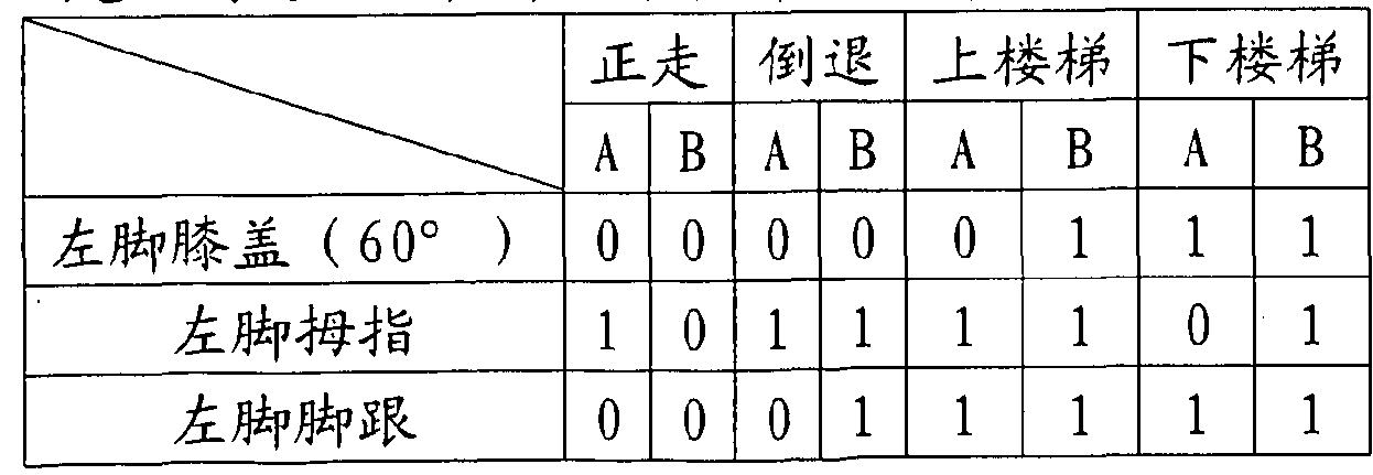
右脚拇指 0 1 0 0 0 0 0 0 Right foot thumb 0 1 0 0 0 0 0 0
右脚脚跟 1 1 1 0 0 0 1 0 Right heel 1 1 1 0 0 0 1 0
当然, 考虑各种干扰因素, 不见得每一步所产生的相位时序都如上表。 本发明可以安装更多感测器在裤子或袜子或衣物上, 以提高辨认的正确率。 例如在裤子臀部装有二个感测器, 则当两足部袜子的感测器都是 " 1" 、 且 两裤子膝部的感测器为 " 1" 、 且臀部感测器也是 "1 " , 即表示使用者坐 着,且椅子高度大于腿的长度导致双腿悬空没有碰触到地。 因为在夏天, 使 用者都穿短裤为多, 固膝关节的感测器改为在大腿部位的裤子放感测器或 裤子在关节(h i t j on i t )设置感测器来取代, 用以侦测人的行动时的腿部运 动, 当然若在裤子上, 所有的位置都放感测器来测步态, 准确度更佳这时 候, 袜子上的感测器无法连接到裤子上的控制器或手机, 故将袜子上的感 测器与鞋子结合,如图 16,其中在袜子上缝有 4个导电丝线 al、 a2、 a3、 a4 相对应在鞋子上有 M、 b2、 b3、 b4的导电材料, 当后脚跟接触地面时, a l 将 bl 的两端接通, 故使 bl 的 " 1" 状态变成 "0" 状态, 同时在鞋子上设 有微处理器来分析、 显示、 储存、 警告或往外传出信号。 Of course, considering various interference factors, the phase timings produced by each step are not as shown above. The present invention can mount more sensors on pants or socks or clothing to improve the accuracy of recognition. For example, if two sensors are installed on the hips of the pants, the sensors of the two-leg socks are "1", and the sensors of the two pants are "1", and the hip sensor is also "1". " , that means the user is sitting, and the height of the chair is greater than the length of the leg, causing the legs to hang without touching the ground. Because in the summer, the user wears shorts, the sensor of the fixed knee joint is replaced by a sensor in the thigh area or a trousers in the joint (hitj on it) sensor to replace the sensor. The leg movement of the person's action, of course, if on the trousers, all the positions are placed on the sensor to measure the gait, the accuracy is better. At this time, the sensor on the sock cannot be connected to the controller on the trousers or Mobile phone, so the sensor on the sock is combined with the shoe, as shown in Figure 16, where there are 4 conductive threads on the socks, a, a2, a3, a4 corresponding to the conductive, M, b2, b3, b4 on the shoes Material, when the heel touches the ground, al turns the two ends of bl on, so that the "1" state of bl becomes "0", and a microprocessor is provided on the shoe for analysis, display, storage, warning. Or send a signal out.
另一只袜子也是如此, 两者间可利用无线通讯, 例如 RFID或 ΖΥΒΕΕ相 互传送资讯, 也可与衣服上的微处理器如控制器或手机互动, 最后再与外 面的监控系统利用无线传输互动。 The same is true for another sock. Wireless communication, such as RFID or video, can be used to transfer information to each other. It can also interact with a microprocessor such as a controller or mobile phone on the clothes, and finally interact with the external monitoring system using wireless transmission. .
当然袜子与鞋子所形成的感测器也可为多段式, 例如图 17所示, 袜子 上有一半球状的导电材料, 而在相对应鞋子的内衬上有一同心的两组导电 线材 bl、 b2 , bl 的线材间距离小于 b2线材间, 故当后腿跟往下压时, 首 先 a l的导电材料,例如导电砂胶或导电金属片先将 bl的两端线材导通, 当 脚跟继续往下压时, a l又将 b2的两端线材导通, 故在脚跟上同一点就有二 段式的压出表现, 而非前面的单一开关或一段式压力感测器, 同时可在袜 子与鞋子不同地方设立多个多段的感测器, 用以感测步态进行时的压力变 化(cop), 此时的压力中心(cop)的每一点又可呈现不同的压力变化, 故当 要表现质量中心(COM)时就可看出人的质量中心(COM)的动态变化, 因为每 一点的表现不是单纯的 "0" 换 "Γ , 而是有所加权, 更能表现出人的质 心(COM)随走动的动态变化。 Of course, the sensor formed by the socks and the shoes can also be multi-stage. For example, as shown in FIG. 17, the socks have a semi-spherical conductive material, and the two sets of conductive wires bl, b2 are concentric on the inner lining of the corresponding shoes. The distance between the wires of bl is less than the distance between the wires of b2, so when the hind legs are pressed down, first the conductive material of al, such as conductive sand or conductive metal sheet, first turns on the wires at both ends of bl, when the heel continues down. When pressed, al turns on the wires at both ends of b2, so there is a two-stage extrusion performance at the same point on the heel, instead of the single switch or one-stage pressure sensor in front, and at the same time in socks and shoes. Multiple multi-segment sensors are installed in different places to sense the pressure change (cop) when the gait is performed. At this point, each point of the pressure center (COP) can exhibit different pressure changes, so the quality should be expressed. At the center (COM), we can see the dynamic change of the human quality center (COM), because the performance of each point is not a simple "0" change "Γ, but a weight, more can show the human centroid (COM ) moving around Of.
我们也可将原先 bl、 b2是利用分开的二个导电丝材来与袜子的导电半 球 a l共同组成的多段式压力感测器, 做更准确的分析, 如图 18 , 利用鞋子 上的可变电组或压电材料或可变电容 cl来取代 bl、 b2 , 如图 18 中可变电 组 cl放在鞋子内村上且一端正好相对应于袜子的 a l半球的球中心位置,在 可变电组 cl的两端测电组质, 则当压力愈大时, al半球与 cl的接触愈多, 导致量测 cl 两端的电组随重力增加而值下降同时可测当 cl 为压电材料或 可变电容时。 此时每一个感测器所得的是模拟信号, 总之, 我们将原先袜 子感测器分开, 有一部分在鞋子, 例如是鞋的内衬与袜子的底面; 或是袜 置摄影机 速规或陀 仪来侦 行动上的加速度及角速度, 以辅助我^所 侦测到的资讯更准确。 We can also use the multi-section pressure sensor composed of two separate conductive wires to form the conductive hemispheres of the socks with a separate bl, b2 for more accurate analysis, as shown in Figure 18, using the variable on the shoes. The electric group or the piezoelectric material or the variable capacitor cl replaces bl, b2. As shown in Fig. 18, the variable electric group cl is placed on the inside of the shoe and one end corresponds to the center position of the ball of the al hemisphere of the sock. When the pressure is measured at both ends of the group cl, the greater the pressure, the more contact the al hemisphere with the cl, causing the electrical groups at both ends of the measurement cl to decrease with the increase of gravity, and the value can be measured when cl is piezoelectric material or When changing the capacitor. At this point, each sensor gets an analog signal. In short, we separate the original sock sensor, some of which are in the shoes, such as the underline of the shoe and the bottom of the sock; or the sock camera speed gauge or the gyroscope To detect the acceleration and angular velocity of the action, to help me to detect the information more accurately.
归纳前述各种步态的时序,可得下列规则,也可用于辨认正走、 倒退、 上 楼梯或下楼梯。 By summarizing the timing of the various gaits described above, the following rules can be obtained, and can also be used to identify the walking, retreating, going up the stairs or going down the stairs.
• 正走: • Walking:
①一般而言, 正走通常是脚跟先着地, 所以脚跟信号会比脚尖先出现。 1 In general, the walking is usually the heel first, so the heel signal will appear first than the toe.
②脚跟着地的时, 该脚的膝盖会是小于 45度的状态。 2 When the heel is on the ground, the knee of the foot will be less than 45 degrees.
• 后退: • Back:
①一般而言,后退通常是脚尖先着地,所以脚尖信号一定要比脚跟信号 提早出现。 1 In general, the back is usually the tip of the toe first, so the toe signal must appear earlier than the heel signal.
②膝盖弯曲超过 60度的信号通常比较接近脚尖信号。 2 Signals with knees bent more than 60 degrees are usually closer to the toe signal.
• 上楼: • Go upstairs:
①该脚的踏地信号出现前, 该脚会出现膝盖弯曲超过 60度的信号。 1 Before the foot signal of the foot appears, the foot will have a signal that the knee bends more than 60 degrees.
②该脚踏地信号出现时, 同时膝盖信号会保持在 60度以上。 2 When the pedal signal appears, the knee signal will remain above 60 degrees.
③该脚膝盖刚打直的信号会出现在该脚的踏地信号内。 3 The signal that the knee has just straightened will appear in the foot signal of the foot.
④通常是脚跟先着地, 所以脚跟信号会先出现。 4 Usually the heel touches the ground first, so the heel signal will appear first.
• 下楼: • Going downstairs:
①脚尖会先着地, 所以脚尖信号会先出现。 1 The tip of the toes will land first, so the toe signal will appear first.
②脚尖讯出现时, 该脚的膝盖信号会是小于 45度状态。 When the toe signal appears, the knee signal of the foot will be less than 45 degrees.
③该脚膝盖刚大于 60度时的信号会出现在该脚的踏地信号时期内。 此外, 可在衣物上加入心跳、 体温、 汗湿、 血氧、 心电图、 血压、 呼 吸等生理感测器与织品感测器相连接, 亦可感测生理机能。 3 The signal when the knee is just greater than 60 degrees will appear in the pedaling signal period of the foot. In addition, a physiological sensor such as heartbeat, body temperature, sweat, blood oxygen, electrocardiogram, blood pressure, and respiration can be attached to the clothing to connect with the fabric sensor, and the physiological function can also be sensed.
第二较佳实施例 Second preferred embodiment
为了使本发明能和一般布料一样耐搓洗且穿着舒适, 本发明使用可曲 挠又耐搓洗的不锈钢丝连接感测器及微控制器, 即以不锈钢丝当传输线,袜 子或衣物裤子当电路板, 不锈钢丝与微控制器之间用服装上常见的按扣或 母子扣连接。 考虑衣物的舒适感, 衣物上的不锈钢丝与按扣或母子扣皆不 宜太多。 若实际应用上有须要安装多个感测器, 本发明可在各织品感测器 旁安装一电阻, 其阻值比例为 2, 然后再串联(图 19B)或并联(图 19A)。 此 原理类似二进制编码, 如图 19B 的电路, 四个感测器可组成的等效电阻有 0, R, 2 R, 3R, 4R, 5R ...最高至 1 5R , 合计 16个数值, 如此可保证不论各织品感 测器如何切换, 串联或并联所成的等效电阻, 都不相同, 即可经由模数转 换(a na 1 og- d i g i 1 conver s i on)之后, 由微控制器分辨各织品感测器的逻 辑状态。 如此可大幅减少导线及按扣或母子扣。 In order to make the invention as washable and comfortable to wear as the general fabric, the present invention uses a flexible and washable stainless steel wire connection sensor and a microcontroller, that is, a stainless steel wire as a transmission line, a sock or a garment trouser as a circuit board. The stainless steel wire and the microcontroller are connected by a common snap or mother-and-pin buckle on the garment. Considering the comfort of the clothes, the stainless steel wire and the snaps or the mother and child buckles on the clothes should not be too much. If it is necessary to install a plurality of sensors in practical applications, the present invention can install a resistor beside each fabric sensor with a resistance ratio of 2, and then in series (Fig. 19B) or in parallel (Fig. 19A). This principle is similar to binary coding. As shown in the circuit of Figure 19B, the equivalent resistance of the four sensors can be 0, R, 2 R, 3R, 4R, 5R ... up to 1 5R, a total of 16 values, so It can guarantee that regardless of how the fabric sensors are switched, the equivalent resistances formed in series or in parallel are different, which can be resolved by the microcontroller after analog-to-digital conversion (a na 1 og- digi 1 conver si on) Logic of each fabric sensor State. This can greatly reduce the wire and snap or mother and child buckle.
第三较佳实施例 Third preferred embodiment
本发明除了分析步态之外, 也可以应用于自行车骑士, 来计算其踩踏 板圏数, 利用轮胎半径为 R,踏一圏为 2 π Ι 从而推估其移动距离及速度,因 为所用的时间由处理器可知。 本发明应用于自行车骑士, 是在两膝关节上 各装一 40及 90度的数字感测器, '骑士走路、 与骑车所得的时序图, 分别 为图 20、 图 21 , 其中右 1及左 1为 40度角感测器, 右 2及左 2为 90度角 感测器。 由于走路时膝关节不会弯超过 90度, 因此图 20中两膝的 90度的 数字感测器皆为 "0", 仅 40度数字感测器切换。 而在骑车时两膝都至少有 40度弯曲, 因此图 21中两膝的 40度的数字感测器皆为 "0" , 仅 90在度数 字感测器切换, 因为在骑车时, 脚底仍踏在自行车的脚踏板上, 故都是导 通 "0" 的状态, 故只好用膝部的感测器且设定在 90度时才有反应, 则使 分别走或骑车, 因为欢脚周 性产生膝部信号_^袜子信号在双 ^都是 的情形只有骑自行车。 故同时也可分辨使用者的行为状态。 : 在行走或骑自行车时, 路况必然会影响步态, 本发明利用摄影机、 加 速规或陀螺仪来测知路况, 并且可提高步态辨识的准确度。 例如自行车行 经坑洞或人突然跌倒时, 加速规或陀螺仪会得到相当大的加速度(例如一个 重力加速度以上)或角度变化, 摄影机也会摄得影像有剧烈的变化, 此时微 控制器可暂停辨识步态, 以免误判, 同时可记录路况。 In addition to analyzing the gait, the present invention can also be applied to a bicycle rider to calculate the pedal pedal number, using the tire radius R, and stepping into a 2 π Ι to estimate the moving distance and speed because of the time used. It is known by the processor. The invention is applied to a bicycle knight, which is equipped with a 40- and 90-degree digital sensor on both knee joints, and the timing chart obtained by the rider and the bicycle is shown in Fig. 20 and Fig. 21, respectively, and right 1 and The left 1 is a 40 degree angle sensor, and the right 2 and left 2 are 90 degree angle sensors. Since the knee joint does not bend more than 90 degrees when walking, the 90-degree digital sensors on both knees in Figure 20 are all "0", and only the 40-degree digital sensor switches. In the bicycle, both knees have at least 40 degrees of bending, so the 40-degree digital sensors on both knees in Figure 21 are both "0", only 90 degrees in the digital sensor switch, because when riding, The sole of the foot is still on the pedal of the bicycle, so it is in the state of turning on "0". Therefore, it is only necessary to use the sensor of the knee and set it at 90 degrees to react, so that it is possible to take or ride separately. Because the foot of the foot produces a knee signal _^ socks signal in the case of double ^ only bicycle riding. Therefore, the user's behavior status can also be distinguished. : When walking or riding a bicycle, the road condition necessarily affects the gait. The present invention uses a camera, an accelerometer or a gyroscope to measure the road condition and improves the accuracy of the gait recognition. For example, when a bicycle passes through a pothole or when a person suddenly falls, the accelerometer or gyroscope will get considerable acceleration (for example, above a gravitational acceleration) or an angle change, and the camera will also take a sharp change in the image. At this time, the microcontroller can Suspend the recognition of the gait to avoid false positives and record road conditions.
第四较佳实施例 Fourth preferred embodiment
若有需要, 一个数字感测器可以有的三个阶段输出, 见图 22。 此数字 感测器的中心为一个嵌入环形导电橡胶或硅胶的球, 下方有导体成十字型, 但中间部分无导体。 当球受到轻压时, 球中最低的环形导电橡胶碰触下方 导体, 但球中较高的环形导电橡胶不会碰触下方导体, 因此只有一组导体 导通; 当球受到重压时,球中高低两个环形导电橡胶都会碰触下方导体, 因 此有两组导体导通, 更重时则球上三组都通, 故在步态分析时, 同一点如 脚跟,不是只有 "0" 或 "1" 的结果,也可有不同压力或受力大小的表现,例 如大于 20千克压力时, 球的第一组导通, 大于 40千克的重力时, 球的二 组导通, 大于 60千克的力时, 球的三组都通, 这样更可表现出步态的分析 结果。 同时压力中心(COP)的表现更具意义, 同为在图 10A的每一个点又可 呈现压力的变化,例如没外力时为 0,压力在 20至 40千克重时为权重 1 , 压 力在 40于 60千克重时权重为 2, 压力大于 60千克重时为权重 3 , 则在足 跟这一点所呈现的值就有 4种变化而非 " 0" 或 "1"。 质量中心(COM)也就 更具意义了, 因为无论质量中心(COM)或压力中心(COP)的意义不只是看步 态分析时受试者的足底的变化,也可得到足底的不同点在步态周期中的受 压力变化情形。 故在进行质量中心(COM)、 全压(tota l pres sure) , 姿势状 态 (pos ture s ta te)、 及全动作质量 (tota l movement mas s)分析时,每一点 都要加权(例如压力在 40至 60千克则权值为 2),另外,我们亦可由 ί F*△ t = MV得到冲量变化, 其中 F为作用力, M是使用者质量, V为速度, A t则为 作用时间, 结果 F* A t即为冲量, 例如在脚踏地的时候, 足跟会加重力道, 由 0到 60千克, 就如前面所述, 则在此变化时间.中, 脚跟所受的力随时间 变化, 导致三段式压力感测器随之变化, 故可得到外力与时间的乘积, 即 为冲量, 故不单纯只是压力中心的分析, 还可得到沖量的时间分析图。 A digital sensor can have three stages of output if needed, see Figure 22. The center of the digital sensor is a ball embedded in a ring-shaped conductive rubber or silica gel with a conductor under the cross, but no conductor in the middle. When the ball is lightly pressed, the lowest annular conductive rubber in the ball touches the lower conductor, but the higher annular conductive rubber in the ball does not touch the lower conductor, so only one set of conductors conducts; when the ball is heavily pressed, Two annular conductive rubbers in the ball will touch the lower conductor, so there are two sets of conductors conducting. When the weight is heavier, the three groups on the ball are all connected. Therefore, in the gait analysis, the same point as the heel is not only "0". Or the result of "1", there may be different pressure or force performance, for example, when the pressure is greater than 20 kg, the first group of the ball is turned on, and when the gravity is greater than 40 kg, the two groups of the ball are turned on, greater than 60 When the force of kilograms is reached, the three groups of the ball are all connected, which can show the analysis result of the gait. At the same time, the performance of the pressure center (COP) is more meaningful. At the same time, the pressure change can be exhibited at each point of FIG. 10A, for example, 0 when there is no external force, 1 for the pressure at 20 to 40 kg, and 40 for the pressure. At a weight of 60 kg, the weight is 2, and when the pressure is greater than 60 kg, the weight is 3, and the value presented at the heel has 4 variations instead of "0" or "1". The Quality Center (COM) is even more meaningful, because the meaning of the center of mass (COM) or pressure center (COP) is not just the change in the sole of the subject when looking at gait analysis, but also the difference in the sole of the foot. Point in the gait cycle The situation of pressure changes. Therefore, when performing mass center (COM), total pressure (tota l pressure), posture state (pos ture ta te), and total motion quality (tota l movement mas s) analysis, each point is weighted (for example, pressure In 40 to 60 kg, the weight is 2). In addition, we can also get the impulse change from ί F*△ t = MV, where F is the force, M is the user mass, V is the speed, and A t is the action time. The result is that F* A t is the impulse. For example, when the foot is on the ground, the heel will add gravity, from 0 to 60 kg. As mentioned above, in this change time, the force on the heel is The time changes, causing the three-stage pressure sensor to change accordingly, so the product of the external force and time can be obtained, that is, the impulse, so it is not just the analysis of the pressure center, but also the time analysis map of the impulse.
第五较佳实施例 Fifth preferred embodiment
脚跟部可装两个以上的数字感测器, 以分辨走路时脚的内侧或外侧先 触地 (俗话是内八或外八字脚), 见图 23。 对于正常人而言, 同一只脚的两 个脚跟的数字感测器, 其触地的时间差多在一小范围之内, 若两脚差别太 大, 可能是某脚受伤或是病变造成, 相同的道理可在袜子放置更多的感测 器, 则我们所侦测到的步态分析结果不是一直线的信号, 而是左右两脚各 为一立体平面的整体足部步态分析的表现。 More than two digital sensors can be mounted on the heel to distinguish the inside or outside of the foot when the foot is touched (except the inner eight or the outer eight feet), as shown in Figure 23. For normal people, the digital sensor of the two heels of the same foot has a time difference of less than a small range. If the two feet are too different, it may be caused by a foot injury or a lesion. The reason is that more sensors can be placed in the socks, and the gait analysis result we detected is not a straight line signal, but the performance of the overall foot gait analysis of the left and right feet as a solid plane.
第六较佳实施例 Sixth preferred embodiment
本发明可实施于肢体互动的电脑游戏, 把身体的动作输入到电脑, 增 加玩家的乐趣。 例如同时把手臂及身体的信号, 藉由上衣来呈现。 有些日 常生活很少发生的步态会在游戏中发生,例如向左或向右横走,见图 24A, 图 24B, 双脚的四个感测器几乎同时触地或离地; 例如踢正步, 见图 25 , 双膝 几无弯曲, 但双脚四个感测器几乎; 例如坐下, 见图 26 , 双膝同时弯曲; 例如跌倒, 在老人或小孩常见, 见图 27, 双脚四个感测器同时触离地。 故 此系统可分析使用者或动物的行为模式; 若有危险时可发出警告。 对于此 类应用, 可以在衣服上、 袜子、 鞋子、 控制盒、 或行动电话加上摄影机加 速规或陀螺仪, 增加游戏模拟式的力量感觉, 以补数字感测的不足, 同时 在真实的步态分析或运动生理上也可增加准确度。 The present invention can be implemented in a computer game in which the body interacts, and the body movements are input to the computer to increase the fun of the player. For example, the signal of the arm and the body is presented by the top. Some gaits that rarely occur in daily life can occur in the game, such as going left or right, see Figure 24A, Figure 24B. The four sensors on both feet touch the ground almost at the same time; for example, kicking See Figure 25. There are few bends on the knees, but the four sensors on the feet are almost; for example, sitting down, see Figure 26, bending both knees; for example, falling, common in old people or children, see Figure 27, feet four The sensors touch the ground at the same time. Therefore, the system can analyze the behavior patterns of users or animals; if there is danger, it can issue a warning. For such applications, you can add camera acceleration gauges or gyroscopes to your clothes, socks, shoes, control boxes, or mobile phones to increase the power of the game's analog power to compensate for the lack of digital sensing while at the same time. State analysis or exercise physiology can also increase accuracy.
第七较佳实施例 Seventh preferred embodiment
本发明在实施时, 难免会碰到不理想的状况, 例如使用者在穿衣、 裤 或袜时没有穿正, 或是剧烈运动后衣、 裤或袜偏离原位, 致使感测器信号 误动作, 最常见的是类似一般机械开关常见的弹跳(bounce) , 形式上是周 期极短(小于 0. 1秒)的脉沖。 为了减少误动作, 本发明考量正常人体状况, 归纳出下列规则, 以便对各感测器输出的信号做前处理。 When the invention is implemented, it is inevitable that it will encounter an unsatisfactory situation, such as the user does not wear the clothes when wearing clothes, pants or socks, or the clothes, pants or socks are deviated from the original position after strenuous exercise, causing the sensor signal to be wrong. The most common is the bounce, which is common in general mechanical switches, and is a pulse with a very short period (less than 0.1 second). In order to reduce malfunctions, the present invention considers the normal human condition and summarizes the following rules in order to pre-process the signals output by the respective sensors.
1. 当大角度膝关节感测器被拉开时, 小角度膝关节感测器必然已被拉 开; 1. When the large angle knee sensor is pulled apart, the small angle knee sensor must have been pulled apart;
2. 以人体的惯性和一般人的肌力, 伸腿屈膝、 抬脚踏地等动作不可能 在小于 K秒时间内完成; 1 在年轻人为 0. 1 , 老年人为 0. 15 , 老年痴 呆症病人为 0.2秒 2. With the inertia of the human body and the muscle strength of the general human body, the movements such as stretching the knees and lifting the pedals can not be completed in less than K seconds; 1 in the young people is 0.1, the elderly is 0. 15 , the old man The patient is 0.2 seconds
依上述规则, 本发明对各感测器信号做前处理的程序如下: According to the above rules, the procedure for pre-processing each sensor signal of the present invention is as follows:
1. 对于以上动作周期小于 K秒的正负脉沖都一律消除; 1. For the above positive and negative pulses with an action period less than K seconds, they are all eliminated;
2. 对于较小角度膝关节感测器, 当有信号显示未被拉开而有较大角度 膝关节感测器被拉开时, 即修改较小角度膝关节感测器信号为已拉 开。 、 2. For smaller angle knee sensor, when the signal display is not pulled open and the knee sensor is pulled out at a large angle, the signal of the smaller angle knee sensor is modified to be opened. . ,
第 佳实施例 . : , The first preferred embodiment . : ,
本发明可利用脚跟与脚尖触地的时间差, 来推估走路的速度, 取得近 似值。 见图 28, 在脚跟与脚尖装设数字感测器(S2与 S1) , 两感测器的距离 即为足底长为一定值 d, 当使用者以速度 V向前走, 我们预测其脚底地面接 触的速度 V' 近似于行走速度 V, 其中如图 28两感测器 S2与 S1接触地面的 时间差为 At, 则可测得速度 V' =d/At, 最后 s (step lengh) =V。t+l/2at 2, 也可算出。 另外, 由 V" =V, +at, 其中 a 为加速度, t为左脚与右脚间隔 的时间, V, 为左脚所测得的速度, V" 则是接下来右脚触地所测得, 则使 用者由左脚到右脚所经过的时间 t 也可得到, 由此可得加速度 a, 则可得 s(step lengh) =V0t+l/2at! 0 我们可由上监测长时间左右脚的步伐长度、 速 度及加速度变化, 因此也可测得步伐长度、 速度、 加速度的变异度 (variability), 由这些资讯的分析也可得到使用者的状态情形, 若要求较 准确的速度, 使用者可以在定速的跑步机上记录至少两种速度的时间差, 在实际应用时以内插法趋近, 或者利用摄影机加速规或陀螺仪来辅助校正 其准确度。以某一使用者在跑步机上(速度设定为 2km/hr)行走的时序图(图 29)为例,第 1至第 6步伐的两感测器 S1与 S2的时间差依序为 0.32, 0.50, 0.15, 0.35, 0.31, 0.30秒, 其两感测器 S1与 S2的距离为 20厘米, 换算 步行速率为 2.0, 1.28, 4.26, 1.83, 2.06, 2.13 km/hr , 另外, 这六个 步伐间的每一个步伐所需的时间为 0.8、 0.88、 0.57 、 0.57、 1.15秒, 故 可得每一步的加速度为 -0.9、 3.39、 -4.26、 0.4、 0.06Km / hr. sec相对 应所算得的步伐(step lengh)为 0.52、 0.67、 0.48、 0.34、 0.69 米 , 这 些测得的加速度 a 例如第一步到第二步为 - 0.9, 导致第二步到第三步的 加速度值为 3.39, ,由此亦可看到第二步所增加的步伐为 0.67, 比第一步 所导致, 接着到了第六步我们可看到加 度为 0. 表示受测者已经^应^ 步机的速度也与跑步机同步。 在步态分析上我们可利用这些参数来评断一 个人的步态是否稳定, 若是数值变化太大亦可能是跌倒的前兆, 即可提供 警讯, 相反的我们亦可利用其当作为虛拟游戏的输入。 The invention can use the time difference between the heel and the toe to touch the ground to estimate the speed of walking and obtain an approximate value. As shown in Figure 28, digital sensors (S2 and S1) are installed on the heel and toe. The distance between the two sensors is a certain value d. When the user moves forward at the speed V, we predict the sole of the foot. The ground contact velocity V' approximates the walking speed V, wherein the time difference between the two sensors S2 and S1 contacting the ground is At, then the velocity V' = d/At can be measured, and finally s (step lengh) = V . t+l/2at 2 can also be calculated. In addition, by V" = V, +at, where a is the acceleration, t is the time between the left foot and the right foot, V is the speed measured by the left foot, and V" is the next right foot touch. If so, the time t elapsed by the user from the left foot to the right foot can also be obtained, so that the acceleration a can be obtained, then s(step lengh) = V 0 t+l/2at ! 0 can be monitored by the upper The length, speed and acceleration of the foot and the foot change, so the variability of the length, speed and acceleration of the step can also be measured. The analysis of the information can also obtain the state of the user, if a more accurate speed is required. The user can record the time difference of at least two speeds on the treadmill at a constant speed, approaching by interpolation in practical applications, or using a camera accelerometer or gyroscope to assist in correcting the accuracy. Taking a timing diagram (Fig. 29) of a user walking on a treadmill (speed setting 2km/hr) as an example, the time difference between the two sensors S1 and S2 at the first to sixth steps is 0.32, 0.50. , 0.15, 0.35, 0.31, 0.30 seconds, the distance between the two sensors S1 and S2 is 20 cm, and the converted walking speed is 2.0, 1.28, 4.26, 1.83, 2.06, 2.13 km/hr, in addition, between these six steps The time required for each step is 0.8, 0.88, 0.57, 0.57, 1.15 seconds, so the acceleration of each step is -0.9, 3.39, -4.26, 0.4, 0.06Km / hr. sec corresponding to the calculated pace (step lengh) is 0.52, 0.67, 0.48, 0.34, 0.69 m. These measured accelerations a are, for example, the first step to the second step are -0.9, resulting in the acceleration values of the second to third steps being 3.39, by This can also be seen that the step added in the second step is 0.67, which is caused by the first step. Then, in the sixth step, we can see that the degree of addition is 0. It means that the subject has already responded to the speed of the step machine. The treadmill is synchronized. In gait analysis, we can use these parameters to judge whether a person's gait is stable. If the value changes too much, it may be a precursor to the fall, and it can provide a warning. On the contrary, we can also use it as a virtual game. Input.
对于关节的角速度, 亦可评估, 例如膝关节设定于 45度及 65度的感 测器, 则角速度 =6/ t, 其中 t为 45度及 60度感应器启动的时间差, L 为小腿长度, Θ为 15度, 则 L*6则可为摆动 45度到 60度之间的距离, 另 外 L*W可当作膝关节的角速度, 故我们亦可测得在摆动期姿态变化的各个 参数, 来评估受测者的稳定度及变异度。 For the angular velocity of the joint, it can also be evaluated. For example, if the knee joint is set at 45 degrees and 65 degrees, the angular velocity = 6 / t, where t is the time difference between the 45 degree and 60 degree sensor activation, L For the calf length, the Θ is 15 degrees, then L*6 can be the distance between 45 and 60 degrees. In addition, L*W can be used as the angular velocity of the knee joint, so we can also measure the attitude change during the swing period. Each parameter is used to assess the stability and variability of the subject.
对于踝关节我们亦可放置两个感测器来侦测其角度, 例如在脚跟与侧 边的两个感测器(S1与 S2)分别代表脚跟着地(10度)及整脚平踩(0度)时, 则这两个感测器所启动的时间差 At即可算出踝关节的角速度 W=10 /At, 如图 30A。 For the ankle joint, we can also place two sensors to detect the angle. For example, the two sensors on the heel and the side (S1 and S2) represent the heel strike (10 degrees) and the whole foot flat (0 At the time of the degree, the time difference At which the two sensors are activated can calculate the angular velocity of the ankle joint W=10 /At, as shown in Fig. 30A.
如果在上坡时, 不再是像平地行走一样, 而是受坡度影响, 因此可由 时间差推估。见图 30B,假设脚在脚跟触地至脚尖触地之间是等速圆周运动, 而在正常行走状况下脚跟触地瞬间, 脚底与地面呈 Θ角(10度), S1与 S2 两感测器触地时间差为 而在上坡时得触地时间差为 At, , 可推得地 面坡度为 Θ*(Δ - At' )/ Δ10 If it is on the uphill slope, it is no longer like walking on the ground, but is affected by the slope, so it can be estimated by the time difference. As shown in Fig. 30B, it is assumed that the foot is in a constant-speed circular motion between the heel touch and the toe touch ground, and in the normal walking condition, the heel touches the ground instantaneously, the sole of the foot is at an angle to the ground (10 degrees), and S1 and S2 are sensed. The time difference between the grounding and the grounding time is At, and the grounding gradient is Θ*(Δ - At' ) / Δ1 0
总之, 有谈到用脚底两点 Sl, S2着地的时间差可得脚底速度 V。 藉量 测得左右脚着地的时间差 ΔΠ、 右脚底速度 V2、 及左脚底速度 VI三者, 由 V2 =Vl+al*Atl, 可推估两脚着地之间的加速度 al; 或藉量测得左脚前后 两次着地的时间差 At2及下一次左脚底速度为 V3, 由 V3=Vl+a2*At2, 亦 可推估左脚前后两次着地的速度 a2。 原则上 Δί2约为 2*Atl。 由上, 本发 明可以测得运动过程中的加速度, 及每次的速度, 然后再加以统计得其变 异度(variability)。 由变异度可知受测者的步态是否平稳, 且可用来预测 下一步的步态为何, 因为当加速度及速度变异度都固定不变时, 速度也就 维持稳定。 再者, 由距离 S=V*t+0.5*a*t2 , 当速度、 加速度及时间差皆稳 定不变时, 即可预估下一步的步行距离 S。 另一方面, 若是加速度、 速度、 距离等数值变化很大, 表示受测者步态异常, 可能必须提出警报, 例如临 时跌倒或撞到其他人或物。 In short, there are two points Sl, S2 landing time difference can get the sole speed V. The borrowing measures the time difference ΔΠ, the right sole velocity V2, and the left sole velocity VI of the left and right feet. From V2 = Vl+al*Atl, the acceleration al between the two feet can be estimated; or the borrowing is measured. The time difference At2 between the left foot and the second foot and the next left foot velocity are V3. From V3=Vl+a2*At2, the speed a2 of the two grounds before and after the left foot can also be estimated. In principle Δί2 is approximately 2*Atl. From the above, the present invention can measure the acceleration during the movement, and the speed of each time, and then statistically obtain its variability. It is known from the variability whether the gait of the subject is stable and can be used to predict the gait of the next step, because the velocity remains stable when the acceleration and velocity variability are fixed. Furthermore, by the distance S=V*t+0.5*a*t 2 , when the speed, acceleration and time difference are both stable, the next walking distance S can be estimated. On the other hand, if the values of acceleration, speed, distance, etc. vary greatly, indicating that the subject's gait is abnormal, an alarm may have to be raised, such as a temporary fall or a collision with another person or thing.
同样的道理也可由关节处的至少两段角度感测器, 可知其关节的角速 度, 利用这次与下次角速度的值及时间差可求得角加速度。 这样的情形下, 若角加速度或角速度的变异度很小, 则可由这一次的角速度预测下一次的 关节运动的角速度, 且由 L=R*e, 其中 R为关节所在的手臂长度, Θ为变 化角度, 可得摆动长度 L。 若角速度及角加速度维持稳定(即变异度低), 则 摆动长度 L即可预测。 The same principle can be obtained from at least two angle sensors at the joint, and the angular velocity of the joint can be known. The angular acceleration can be obtained by using the value of this and the next angular velocity and the time difference. In such a case, if the angular acceleration or the angular variability is small, the angular velocity of the next joint motion can be predicted from the angular velocity of this time, and by L = R * e, where R is the length of the arm where the joint is located, The angle of change gives the length L of the swing. If the angular velocity and angular acceleration remain stable (ie, the variability is low), the swing length L can be predicted.
第九较佳实施例 Ninth preferred embodiment
本发明可利用膝关节感测器被拉开的时间长短, 来推估上下坡或上下 楼梯的坡度, 取得近似值。 当坡度愈陡, 腿必须抬得愈高, 膝关节愈弯曲, 膝关节感测器被拉开的时间也就愈长, 当然我们也可在裤子上设置多段感 测器, 例如: 45度、 60度、 75度三段, 当膝关节由直开始弯, 刚开始只有 45度感测器有产生 'Τ' , 接下来是 45度及 60度感测器都产生 " , 若 是连 75度感测器都是 " , 则代表屈膝角度更大, 意即坡度愈陡。 The present invention can estimate the slope of the upslope or ups and downs of stairs by using the length of time the knee joint sensor is pulled apart, and obtain an approximate value. The steeper the slope, the higher the leg must be lifted, the more the knee joint is bent, and the longer the knee sensor is pulled apart. Of course, we can also set a multi-segment sensor on the trousers, for example: 45 degrees, 60 degrees, 75 degrees three segments, when the knee joint is straight from the beginning, only the 45 degree sensor has produced 'Τ', and the next 45 degrees and 60 degrees sensor are generated", if Even if the 75-degree sensor is "", it means that the angle of the knee is larger, which means that the steeper the slope.
第十较佳实施例 Tenth preferred embodiment
在图 31为步态分析的流程, 我们可知当使用者前进时脚的脚跟也是先 着地, 但是若地面为上坡地则脚跟着地时间与脚尖着地时间差变短。 相反 地, 若是下坡, 则是前脚尖先着地, 下坡角度大些, 则脚尖与后脚跟所受 的压力分布相反, 即压力会移到脚尖, 这就像穿高跟鞋。 若是再加上上身 的姿态变化, 如图 31, 其中, A所代表着是, 当使用者姿势改变时, 感应 器也同时反应, 并由(身上)多种感测器所提供的资讯来接收开或关 on/off 的相关信号; B所代表着是提供一个资料库, 藉此来比较开或关 on/of f 的 相关信号, 藉此来判断使用者的姿势变化; C所提供的是使用者同时进行的 姿势变化的 3D立体资讯, 则更可准确的侦测到受测者的姿势变化, 亦即可 知道当时人的姿势状态, 例如表 2。 In Fig. 31, the flow of the gait analysis, we know that the heel of the foot is also the first when the user advances, but if the ground is uphill, the time difference between the heel strike time and the toe landing time becomes shorter. Conversely, if it is downhill, the forefoot will land first and the downhill angle will be larger. The pressure distribution on the toe and the heel will be opposite, ie the pressure will move to the toes, which is like wearing high heels. If it is added to the posture change of the upper body, as shown in Figure 31, where A stands for, when the user's posture changes, the sensor also responds at the same time, and is received by the information provided by the various sensors. Turn on or off the relevant signal on/off; B stands for providing a database to compare the on/off related signals on or off to determine the user's posture change; The 3D stereoscopic information of the posture change made by the user at the same time can more accurately detect the change of the posture of the subject, and can also know the posture state of the person at that time, for example, Table 2.
表 2: Table 2:
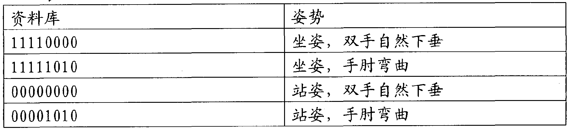
其中, 资料库中的 8位字符串从右到左依次代表右腋, 右肘, 左腋, 左肘, 右臀, 右膝, 左臀, 左膝。 Among them, the 8-bit string in the database from right to left represents right 腋, right elbow, left 腋, left elbow, right hip, right knee, left hip, left knee.
Claims
Priority Applications (5)
| Application Number | Priority Date | Filing Date | Title |
|---|---|---|---|
| PCT/CN2009/000999 WO2011026257A1 (en) | 2009-09-03 | 2009-09-03 | System and method for analyzing gait by fabric sensors |
| JP2012527179A JP5747034B2 (en) | 2009-09-03 | 2010-09-03 | Fabric sensing system gait analysis system and method |
| PCT/CN2010/001341 WO2011026316A1 (en) | 2009-09-03 | 2010-09-03 | System and method for analyzing gait using fabric sensors |
| CN201080039602.8A CN102781319B (en) | 2009-09-03 | 2010-09-03 | Gait analysis system and method of fabric sensor |
| US13/412,286 US8961439B2 (en) | 2009-09-03 | 2012-03-05 | System and method for analyzing gait using fabric sensors |
Applications Claiming Priority (1)
| Application Number | Priority Date | Filing Date | Title |
|---|---|---|---|
| PCT/CN2009/000999 WO2011026257A1 (en) | 2009-09-03 | 2009-09-03 | System and method for analyzing gait by fabric sensors |
Related Parent Applications (1)
| Application Number | Title | Priority Date | Filing Date |
|---|---|---|---|
| PCT/CN2010/001341 Continuation-In-Part WO2011026316A1 (en) | 2009-09-03 | 2010-09-03 | System and method for analyzing gait using fabric sensors |
Related Child Applications (1)
| Application Number | Title | Priority Date | Filing Date |
|---|---|---|---|
| US13/412,286 Continuation-In-Part US8961439B2 (en) | 2009-09-03 | 2012-03-05 | System and method for analyzing gait using fabric sensors |
Publications (1)
| Publication Number | Publication Date |
|---|---|
| WO2011026257A1 true WO2011026257A1 (en) | 2011-03-10 |
Family
ID=43648825
Family Applications (2)
| Application Number | Title | Priority Date | Filing Date |
|---|---|---|---|
| PCT/CN2009/000999 Ceased WO2011026257A1 (en) | 2009-09-03 | 2009-09-03 | System and method for analyzing gait by fabric sensors |
| PCT/CN2010/001341 Ceased WO2011026316A1 (en) | 2009-09-03 | 2010-09-03 | System and method for analyzing gait using fabric sensors |
Family Applications After (1)
| Application Number | Title | Priority Date | Filing Date |
|---|---|---|---|
| PCT/CN2010/001341 Ceased WO2011026316A1 (en) | 2009-09-03 | 2010-09-03 | System and method for analyzing gait using fabric sensors |
Country Status (3)
| Country | Link |
|---|---|
| US (1) | US8961439B2 (en) |
| JP (1) | JP5747034B2 (en) |
| WO (2) | WO2011026257A1 (en) |
Cited By (5)
| Publication number | Priority date | Publication date | Assignee | Title |
|---|---|---|---|---|
| CN103211604A (en) * | 2013-05-07 | 2013-07-24 | 河北工程大学 | Sitting-position psychological state detecting device and detecting method |
| CN104027107A (en) * | 2014-05-23 | 2014-09-10 | 浙江大学 | Wearable electrocardio measurement device |
| CN105388495A (en) * | 2014-08-20 | 2016-03-09 | 博能电子公司 | Estimating local motion of physical exercise |
| CN105476639A (en) * | 2015-11-20 | 2016-04-13 | 南京中科创达软件科技有限公司 | Electronic equipment for detecting and correcting splayfeet |
| CN108562384A (en) * | 2012-12-13 | 2018-09-21 | 耐克创新有限合伙公司 | Clothes with sensing system |
Families Citing this family (152)
| Publication number | Priority date | Publication date | Assignee | Title |
|---|---|---|---|---|
| US8647287B2 (en) | 2008-12-07 | 2014-02-11 | Andrew Greenberg | Wireless synchronized movement monitoring apparatus and system |
| US8880358B2 (en) * | 2010-04-16 | 2014-11-04 | Thomas J. Cunningham | Sensing device |
| KR102009711B1 (en) * | 2011-02-07 | 2019-08-12 | 뉴우바란스아스레틱스인코포레이팃드 | Systems and methods for monitoring athletic performance |
| JP5728689B2 (en) * | 2011-05-17 | 2015-06-03 | 株式会社国際電気通信基礎技術研究所 | Walking signal generation device and walking signal generation system |
| FR2976700B1 (en) * | 2011-06-17 | 2013-07-12 | Inst Nat Rech Inf Automat | METHOD FOR GENERATING COMMAND COORDINATION CONTROL ORDERS FOR DISPLACING AN ANIMATED PLATFORM AND CORRESPONDING GENERATOR. |
| US9524424B2 (en) | 2011-09-01 | 2016-12-20 | Care Innovations, Llc | Calculation of minimum ground clearance using body worn sensors |
| US9165113B2 (en) * | 2011-10-27 | 2015-10-20 | Intel-Ge Care Innovations Llc | System and method for quantitative assessment of frailty |
| US9339691B2 (en) | 2012-01-05 | 2016-05-17 | Icon Health & Fitness, Inc. | System and method for controlling an exercise device |
| US9078478B2 (en) * | 2012-07-09 | 2015-07-14 | Medlab, LLC | Therapeutic sleeve device |
| US8983637B2 (en) | 2012-07-30 | 2015-03-17 | Mapmyfitness, Inc. | Determining authenticity of reported fitness-related activities |
| US9877667B2 (en) | 2012-09-12 | 2018-01-30 | Care Innovations, Llc | Method for quantifying the risk of falling of an elderly adult using an instrumented version of the FTSS test |
| WO2014109799A1 (en) | 2012-09-17 | 2014-07-17 | President And Fellows Of Harvard College | Soft exosuit for assistance with human motion |
| US10042893B2 (en) | 2012-10-31 | 2018-08-07 | Under Armour, Inc. | System and method for personal and peer performance ranking of outdoor activities |
| US9700241B2 (en) | 2012-12-04 | 2017-07-11 | Under Armour, Inc. | Gait analysis system and method |
| US9864780B2 (en) * | 2012-12-06 | 2018-01-09 | Autonomous_Id Canada Inc. | Gait-based biometric data analysis system |
| KR101428325B1 (en) * | 2012-12-27 | 2014-08-07 | 현대자동차주식회사 | Robot foot apparatus |
| JP5811360B2 (en) * | 2012-12-27 | 2015-11-11 | カシオ計算機株式会社 | Exercise information display system, exercise information display method, and exercise information display program |
| WO2014104360A1 (en) * | 2012-12-28 | 2014-07-03 | 株式会社東芝 | Motion information processing device and method |
| US12161477B1 (en) * | 2013-01-19 | 2024-12-10 | Bertec Corporation | Force measurement system |
| US11857331B1 (en) * | 2013-01-19 | 2024-01-02 | Bertec Corporation | Force measurement system |
| US12453853B2 (en) | 2013-01-21 | 2025-10-28 | Cala Health, Inc. | Multi-modal stimulation for treating tremor |
| CN114768089A (en) | 2013-01-21 | 2022-07-22 | 卡拉健康公司 | Apparatus and method for controlling tremor |
| CN105210067B (en) * | 2013-03-04 | 2021-04-30 | 博能电子公司 | Calculate the user's physical state related to physical exercise |
| RU2531689C1 (en) * | 2013-03-05 | 2014-10-27 | Общество С Ограниченной Ответственностью "Хилби" | Method for monitoring individual's motion load and inner sole for implementing it |
| RU2531697C1 (en) * | 2013-03-05 | 2014-10-27 | Общество С Ограниченной Ответственностью "Хилби" | Method for determining individual's weight and inner sole for implementing it |
| US9254409B2 (en) | 2013-03-14 | 2016-02-09 | Icon Health & Fitness, Inc. | Strength training apparatus with flywheel and related methods |
| EP2783630A1 (en) * | 2013-03-27 | 2014-10-01 | ETH Zurich | Human motion analysis method and device |
| US8736439B1 (en) * | 2013-04-06 | 2014-05-27 | Kenneth Feng Shinozuka | Sock for bed-departure detection |
| TWI562100B (en) * | 2013-05-03 | 2016-12-11 | Ind Tech Res Inst | Device and method for monitoring postural and movement balance for fall prevention |
| EP3777677B1 (en) | 2013-05-31 | 2024-11-06 | President And Fellows Of Harvard College | Soft exosuit for assistance with human motion |
| JP6359343B2 (en) * | 2013-07-01 | 2018-07-18 | キヤノンメディカルシステムズ株式会社 | Motion information processing apparatus and method |
| US20150068069A1 (en) * | 2013-07-27 | 2015-03-12 | Alexander Bach Tran | Personally powered appliance |
| JP5888309B2 (en) * | 2013-10-31 | 2016-03-22 | カシオ計算機株式会社 | Training support apparatus and system, form analysis apparatus and method, and program |
| US9443063B2 (en) | 2013-12-06 | 2016-09-13 | President And Fellows Of Harvard College | Method and apparatus for using gait analysis to determine a health quality measure |
| US9445769B2 (en) * | 2013-12-06 | 2016-09-20 | President And Fellows Of Harvard College | Method and apparatus for detecting disease regression through network-based gait analysis |
| EP4104757B1 (en) | 2013-12-09 | 2024-10-02 | President and Fellows of Harvard College | Assistive flexible suits, flexible suit systems, and methods for making and control thereof to assist human mobility |
| EP3623020B1 (en) | 2013-12-26 | 2024-05-01 | iFIT Inc. | Magnetic resistance mechanism in a cable machine |
| US9801568B2 (en) * | 2014-01-07 | 2017-10-31 | Purdue Research Foundation | Gait pattern analysis for predicting falls |
| EP3102171A4 (en) | 2014-02-05 | 2018-03-28 | President and Fellows of Harvard College | Systems, methods, and devices for assisting walking for developmentally-delayed toddlers |
| US20150254992A1 (en) * | 2014-03-06 | 2015-09-10 | Maneesh SETHI | Memory-enhancing and habit-training methods and devices |
| WO2015138339A1 (en) * | 2014-03-10 | 2015-09-17 | Icon Health & Fitness, Inc. | Pressure sensor to quantify work |
| WO2015157731A1 (en) | 2014-04-10 | 2015-10-15 | President And Fellows Of Harvard College | Orthopedic device including protruding members |
| AU2015271774B2 (en) | 2014-06-02 | 2020-04-16 | Cala Health, Inc. | Systems and methods for peripheral nerve stimulation to treat tremor |
| TWI559144B (en) * | 2014-06-05 | 2016-11-21 | zhi-zhen Chen | Scale - guided limb rehabilitation system |
| CN106470739B (en) | 2014-06-09 | 2019-06-21 | 爱康保健健身有限公司 | Cable system incorporated into the treadmill |
| US9288556B2 (en) * | 2014-06-18 | 2016-03-15 | Zikto | Method and apparatus for measuring body balance of wearable device |
| WO2015195965A1 (en) | 2014-06-20 | 2015-12-23 | Icon Health & Fitness, Inc. | Post workout massage device |
| JP6080078B2 (en) * | 2014-08-18 | 2017-02-15 | 高知県公立大学法人 | Posture and walking state estimation device |
| US20170277138A1 (en) * | 2014-09-04 | 2017-09-28 | Leomo, Inc. | Information terminal device, motion capture system and motion capture method |
| JP6113934B2 (en) * | 2014-09-18 | 2017-04-12 | 一博 椎名 | Recording device, portable terminal, analysis device, program, and storage medium |
| EP3194769B1 (en) * | 2014-09-19 | 2020-04-08 | President and Fellows of Harvard College | Soft exosuit for assistance with human motion |
| CN104287743B (en) * | 2014-10-23 | 2016-03-23 | 东南大学 | A multi-joint angle integrated serial detection system based on flexible fabric |
| KR20160075118A (en) * | 2014-12-19 | 2016-06-29 | 한국산업기술대학교산학협력단 | System for Estimating the Center of Pressure in Gait Rehabilitation Robots and method thereof |
| US10258828B2 (en) | 2015-01-16 | 2019-04-16 | Icon Health & Fitness, Inc. | Controls for an exercise device |
| US20160253891A1 (en) * | 2015-02-27 | 2016-09-01 | Elwha Llc | Device that determines that a subject may contact a sensed object and that warns of the potential contact |
| US10391361B2 (en) | 2015-02-27 | 2019-08-27 | Icon Health & Fitness, Inc. | Simulating real-world terrain on an exercise device |
| CN104799862B (en) * | 2015-04-02 | 2018-06-19 | 中国海洋大学 | A kind of human body is unbalance method for early warning and system |
| TWI554266B (en) * | 2015-04-24 | 2016-10-21 | Univ Nat Yang Ming | Wearable gait rehabilitation training device and gait training method using the same |
| JP6552875B2 (en) * | 2015-05-28 | 2019-07-31 | 株式会社早稲田エルダリーヘルス事業団 | Moving motion analysis apparatus, method and program |
| US10248188B2 (en) * | 2015-06-03 | 2019-04-02 | James M. O'Neil | System and method for generating wireless signals and controlling digital responses from physical movement |
| JP2018516702A (en) | 2015-06-10 | 2018-06-28 | カラ ヘルス, インコーポレイテッドCala Health, Inc. | System and method for peripheral nerve stimulation for treating tremor with removable therapeutic devices and monitoring devices |
| US9836118B2 (en) | 2015-06-16 | 2017-12-05 | Wilson Steele | Method and system for analyzing a movement of a person |
| US12366496B2 (en) | 2015-06-23 | 2025-07-22 | Motion Metrics Limited | Methods for calibrating a motion and ground reaction force analysis system |
| JP6554996B2 (en) * | 2015-08-17 | 2019-08-07 | トヨタ自動車株式会社 | Walking training apparatus and walking training method thereof |
| US10953305B2 (en) | 2015-08-26 | 2021-03-23 | Icon Health & Fitness, Inc. | Strength exercise mechanisms |
| US20180140225A1 (en) * | 2015-09-21 | 2018-05-24 | Figur8, Inc. | Body part deformation analysis using wearable body sensors |
| US10603482B2 (en) | 2015-09-23 | 2020-03-31 | Cala Health, Inc. | Systems and methods for peripheral nerve stimulation in the finger or hand to treat hand tremors |
| US9978247B2 (en) | 2015-09-24 | 2018-05-22 | Microsoft Technology Licensing, Llc | Smart fabric that detects events and generates notifications |
| CN108028021B (en) * | 2015-09-29 | 2021-10-15 | 索尼公司 | Information processing apparatus, information processing method and program |
| TWI582389B (en) * | 2015-10-26 | 2017-05-11 | 行政院原子能委員會核能研究所 | Navigation system for inertial positioning with gait detection method |
| EP3442417A1 (en) * | 2016-01-07 | 2019-02-20 | Gunther Röder | Method and device for detecting a fall |
| WO2017132067A2 (en) | 2016-01-21 | 2017-08-03 | Cala Health, Inc. | Systems, methods and devices for peripheral neuromodulation for treating diseases related to overactive bladder |
| TWI615129B (en) * | 2016-02-19 | 2018-02-21 | 財團法人資訊工業策進會 | Gait analysis system and method thereof |
| US10716495B1 (en) | 2016-03-11 | 2020-07-21 | Fortify Technologies, LLC | Accelerometer-based gait analysis |
| CN109069278A (en) | 2016-03-13 | 2018-12-21 | 哈佛大学校长及研究员协会 | Flexible member for anchoring to the body |
| US10625137B2 (en) | 2016-03-18 | 2020-04-21 | Icon Health & Fitness, Inc. | Coordinated displays in an exercise device |
| US10272317B2 (en) | 2016-03-18 | 2019-04-30 | Icon Health & Fitness, Inc. | Lighted pace feature in a treadmill |
| US10493349B2 (en) | 2016-03-18 | 2019-12-03 | Icon Health & Fitness, Inc. | Display on exercise device |
| US10293211B2 (en) | 2016-03-18 | 2019-05-21 | Icon Health & Fitness, Inc. | Coordinated weight selection |
| US10561894B2 (en) | 2016-03-18 | 2020-02-18 | Icon Health & Fitness, Inc. | Treadmill with removable supports |
| WO2017192409A2 (en) | 2016-05-04 | 2017-11-09 | Allen Selner | Instrumented orthotic |
| US10252109B2 (en) | 2016-05-13 | 2019-04-09 | Icon Health & Fitness, Inc. | Weight platform treadmill |
| US10441844B2 (en) | 2016-07-01 | 2019-10-15 | Icon Health & Fitness, Inc. | Cooling systems and methods for exercise equipment |
| US10471299B2 (en) | 2016-07-01 | 2019-11-12 | Icon Health & Fitness, Inc. | Systems and methods for cooling internal exercise equipment components |
| CN109689151B (en) | 2016-07-08 | 2024-07-30 | 卡拉健康公司 | System and method for stimulating N nerves with exactly N electrodes and improved dry electrodes |
| GB2601710B (en) * | 2016-07-13 | 2022-11-23 | Palarum Llc | Patient monitoring system |
| CN109789543B (en) | 2016-07-22 | 2022-09-27 | 哈佛大学校长及研究员协会 | Control optimization for wearable systems |
| US12181352B2 (en) | 2021-06-03 | 2024-12-31 | Sigmasense, Llc. | Insole XYZ force detection system |
| US11246507B2 (en) * | 2016-08-18 | 2022-02-15 | Sigmasense, Llc. | Wireless in-shoe physical activity monitoring apparatus |
| US12194344B2 (en) | 2016-08-18 | 2025-01-14 | Sigmasense, Llc. | Plurality of layers of pressure sensors within a foot force detection system |
| US12207703B2 (en) | 2016-08-18 | 2025-01-28 | Sigmasense, Llc. | Shoe to shoe communication within a foot force detection system |
| US12121773B2 (en) | 2016-08-18 | 2024-10-22 | Sigmasense, Llc. | Personal athlete monitoring system |
| US12226674B2 (en) | 2016-08-18 | 2025-02-18 | Sigmasense, Llc. | Power harvesting in a foot force detection system |
| US12225979B2 (en) | 2016-08-18 | 2025-02-18 | Sigmasense, Llc. | Variable sampling rate within a foot force detection system |
| EP3503959A4 (en) | 2016-08-25 | 2020-01-15 | Cala Health, Inc. | SYSTEMS AND METHODS FOR TREATING CARDIAL DYSFUNCTION BY PERIPHERAL NERVOUS STIMULATION |
| US10671705B2 (en) | 2016-09-28 | 2020-06-02 | Icon Health & Fitness, Inc. | Customizing recipe recommendations |
| US10500473B2 (en) | 2016-10-10 | 2019-12-10 | Icon Health & Fitness, Inc. | Console positioning |
| US10207148B2 (en) | 2016-10-12 | 2019-02-19 | Icon Health & Fitness, Inc. | Systems and methods for reducing runaway resistance on an exercise device |
| US10376736B2 (en) | 2016-10-12 | 2019-08-13 | Icon Health & Fitness, Inc. | Cooling an exercise device during a dive motor runway condition |
| DE102016220660B4 (en) * | 2016-10-21 | 2019-03-07 | Robert Bosch Gmbh | Device, control unit, electric bicycle and method for detecting a movement sequence of a two-wheeled driver, as well as for controlling a motor |
| US10661114B2 (en) | 2016-11-01 | 2020-05-26 | Icon Health & Fitness, Inc. | Body weight lift mechanism on treadmill |
| TWI646997B (en) | 2016-11-01 | 2019-01-11 | 美商愛康運動與健康公司 | Distance sensor for console positioning |
| JP6508174B2 (en) * | 2016-11-29 | 2019-05-08 | カシオ計算機株式会社 | Running analysis device, running analysis method and running analysis program |
| JP6482106B2 (en) * | 2016-11-30 | 2019-03-13 | リオモ インクLEOMO, Inc. | Motion capture system, motion capture program, and motion capture method |
| TWI680782B (en) | 2016-12-05 | 2020-01-01 | 美商愛康運動與健康公司 | Offsetting treadmill deck weight during operation |
| TWI628524B (en) * | 2016-12-12 | 2018-07-01 | 長庚大學 | Somatosensory control system and method thereof |
| US10272293B2 (en) * | 2016-12-23 | 2019-04-30 | Industrial Technology Research Institute | Body motion analysis system, portable device and body motion analysis method |
| US10758160B2 (en) | 2017-01-20 | 2020-09-01 | Figur8, Inc. | Body part motion analysis with wearable sensors |
| KR101924441B1 (en) * | 2017-01-26 | 2018-12-03 | 주식회사 제윤메디컬 | Method, Apparatus and System for measuring body balance using Smart Insole |
| KR101909743B1 (en) * | 2017-01-26 | 2018-10-18 | 주식회사 제윤메디컬 | Method and system for controlling electrical equipment for vehicles based on Smart Insole |
| JP6834553B2 (en) * | 2017-02-09 | 2021-02-24 | セイコーエプソン株式会社 | Motion analysis system, motion analysis device, motion analysis program and motion analysis method |
| CN108567196A (en) * | 2017-03-09 | 2018-09-25 | 清远广硕技研服务有限公司 | Capacitive pressure detects insole and its operation method |
| US11014804B2 (en) | 2017-03-14 | 2021-05-25 | President And Fellows Of Harvard College | Systems and methods for fabricating 3D soft microstructures |
| KR101856077B1 (en) * | 2017-03-21 | 2018-05-09 | 스피나 시스템즈 주식회사 | Walking Calibrator Using Smart Insole |
| EP3606604A4 (en) | 2017-04-03 | 2020-12-16 | Cala Health, Inc. | SYSTEMS, METHODS AND DEVICES FOR PERIPHERAL NEUROMODULATION FOR THE TREATMENT OF DISEASES RELATED TO OVERACTIVE BLADDER |
| TWI655931B (en) * | 2017-05-12 | 2019-04-11 | 美思科技股份有限公司 | Wearable physiological monitoring device |
| US11253173B1 (en) * | 2017-05-30 | 2022-02-22 | Verily Life Sciences Llc | Digital characterization of movement to detect and monitor disorders |
| WO2018232266A2 (en) * | 2017-06-16 | 2018-12-20 | Medstar Health | Systems and methods for injury prevention and rehabilitation |
| WO2019022533A1 (en) * | 2017-07-28 | 2019-01-31 | 충남대학교 산학협력단 | Smart shoe system that judges the wearer's walking condition |
| KR102064591B1 (en) * | 2017-07-31 | 2020-01-09 | 충남대학교산학협력단 | Smart shoes system for calculating energy expenditure |
| TWI744546B (en) | 2017-08-16 | 2021-11-01 | 美商愛康運動與健康公司 | Systems for providing torque resisting axial impact |
| KR101899129B1 (en) * | 2017-11-07 | 2018-10-31 | 전자부품연구원 | Apparatus and method for analysis of exercising posture using textile sensor |
| US10729965B2 (en) | 2017-12-22 | 2020-08-04 | Icon Health & Fitness, Inc. | Audible belt guide in a treadmill |
| WO2019143790A1 (en) | 2018-01-17 | 2019-07-25 | Cala Health, Inc. | Systems and methods for treating inflammatory bowel disease through peripheral nerve stimulation |
| US11624755B2 (en) | 2018-02-21 | 2023-04-11 | Georgia Tech Research Corporation | Gait-pace meter and methods of determining gait speed |
| WO2019163714A1 (en) * | 2018-02-26 | 2019-08-29 | 国立大学法人お茶の水女子大学 | Movement determination device, movement determination system, movement determination method, and program |
| JP7405759B2 (en) * | 2018-03-13 | 2023-12-26 | キュオン アー・ゲー | Gait correction system to prevent degenerative diseases of joints and ligaments in dogs |
| US10325472B1 (en) * | 2018-03-16 | 2019-06-18 | Palarum Llc | Mount for a patient monitoring device |
| US10716492B2 (en) * | 2018-03-30 | 2020-07-21 | Bay West Veterinary Surgery, Inc. | Quadruped lameness detection |
| ES2736261B2 (en) * | 2018-06-25 | 2021-04-29 | Univ Coruna | PROCEDURE, CONTROL MODULE, AND COMPUTER PROGRAM PRODUCT TO CONTROL A SYSTEM TO MEASURE THE AMOUNT OF SCAFOID DISPLACEMENT OF A SUBJECT |
| US11672480B2 (en) * | 2018-07-09 | 2023-06-13 | V Reuben F. Burch | Wearable flexible sensor motion capture system |
| US11373452B2 (en) * | 2018-08-07 | 2022-06-28 | Georgetown University | Multidimensional analysis of gait in rodent |
| CN113396085B (en) | 2018-11-29 | 2025-03-14 | 格罗特工业有限公司 | Smart cable systems for truck trailers |
| US11039761B2 (en) * | 2018-12-14 | 2021-06-22 | At&T Intellectual Property I, L.P. | Fall prediction based on electroencephalography and gait analysis data |
| US10842413B2 (en) * | 2019-04-19 | 2020-11-24 | National Taiwan University | Piezoelectric patch sensor |
| JP7127738B2 (en) * | 2019-05-29 | 2022-08-30 | 日本電気株式会社 | Information processing device, weight estimation device, weight estimation system, information processing method, and storage medium |
| US20220211297A1 (en) * | 2019-05-29 | 2022-07-07 | Nec Corporation | Information processing device, walking environment determination device, walking environment determination system, information processing method, and storage medium |
| TWI749343B (en) | 2019-07-23 | 2021-12-11 | 緯創資通股份有限公司 | Wearable device and method of operating the same |
| US12251560B1 (en) | 2019-08-13 | 2025-03-18 | Cala Health, Inc. | Connection quality determination for wearable neurostimulation systems |
| US11890468B1 (en) | 2019-10-03 | 2024-02-06 | Cala Health, Inc. | Neurostimulation systems with event pattern detection and classification |
| US10863928B1 (en) * | 2020-01-28 | 2020-12-15 | Consensus Orthopedics, Inc. | System and methods for monitoring the spine, balance, gait, or posture of a patient |
| JP7283422B2 (en) * | 2020-03-06 | 2023-05-30 | 豊田合成株式会社 | Gait diagnosis system |
| US12115000B2 (en) * | 2020-09-24 | 2024-10-15 | SportScientia Pte. Ltd. | Sock for monitoring human lower limb and foot performance |
| EP4258988A1 (en) * | 2020-12-14 | 2023-10-18 | Universiteit Twente | Footwear sensors for human movement measurement |
| WO2022132764A1 (en) * | 2020-12-15 | 2022-06-23 | Arizona Board Of Regents On Behalf Of Arizona State University | Methods and systems for capturing and visualizing spinal motion |
| JP7543979B2 (en) * | 2021-05-12 | 2024-09-03 | トヨタ自動車株式会社 | Load measurement system, walking training system, load measurement method and program |
| WO2022266247A1 (en) * | 2021-06-15 | 2022-12-22 | My Medical Hub Corporation | Abnormal gait detection based on 2d human pose estimation |
| EP4154811B1 (en) * | 2021-09-22 | 2024-10-23 | Industrial Technology Research Institute | Gait evaluating system |
| CN115500814B (en) * | 2022-10-14 | 2025-01-28 | 复旦大学 | An in vivo multi-dimensional stress-strain detection device for plantar soft tissue |
| DE102023120648B3 (en) * | 2023-08-03 | 2024-12-19 | Hochschule Offenburg, Körperschaft des öffentlichen Rechts | Method for generating and/or processing motion data, method for detecting and/or evaluating motion sequences, method for detecting and/or evaluating dynamic instabilities, method for generating and/or optimizing algorithms and/or models, device for carrying out such methods and computer program |
| WO2025034467A1 (en) * | 2023-08-04 | 2025-02-13 | Active Protective Technologies, Inc. | Periodic motion based pedestrian dead reckoning |
| CN117752324B (en) * | 2023-12-05 | 2024-06-11 | 上海脊合医疗科技有限公司 | Scoliosis detection method and system based on muscle current signals |
Citations (4)
| Publication number | Priority date | Publication date | Assignee | Title |
|---|---|---|---|---|
| WO2001039655A2 (en) * | 1999-12-06 | 2001-06-07 | Trustees Of Boston University | In-shoe remote telemetry gait analysis system |
| WO2008058048A2 (en) * | 2006-11-06 | 2008-05-15 | Colorado Seminary, Which Owns And Operates The University Of Denver | Smart apparatus for gait monitoring and fall prevention |
| US20080146968A1 (en) * | 2006-12-14 | 2008-06-19 | Masuo Hanawaka | Gait analysis system |
| CN201135440Y (en) * | 2007-07-24 | 2008-10-22 | 中国科学院理化技术研究所 | A tiny measuring device for recording human gait information |
Family Cites Families (11)
| Publication number | Priority date | Publication date | Assignee | Title |
|---|---|---|---|---|
| CN2040365U (en) * | 1988-08-20 | 1989-07-05 | 中国人民解放军北京军区总医院 | Inertia walking state tester |
| US5546955A (en) * | 1992-06-18 | 1996-08-20 | Wilk; Peter J. | Medical stocking for temperature detection |
| US6922592B2 (en) * | 2000-04-04 | 2005-07-26 | Medtronic, Inc. | Implantable medical device controlled by a non-invasive physiological data measurement device |
| EP1675509A1 (en) * | 2003-10-17 | 2006-07-05 | M.B.T.L. Limited | Measuring forces in athletics |
| JP4374596B2 (en) * | 2004-01-30 | 2009-12-02 | 学校法人同志社 | Load measurement method |
| WO2006016369A2 (en) * | 2004-08-11 | 2006-02-16 | Andante Medical Devices Ltd. | Sports shoe with sensing and control |
| US8028443B2 (en) * | 2005-06-27 | 2011-10-04 | Nike, Inc. | Systems for activating and/or authenticating electronic devices for operation with footwear |
| DE102005055842A1 (en) * | 2005-11-23 | 2007-05-24 | Alpha-Fit Gmbh | Pressure sensor for incorporation in clinical test socks or stockings incorporates pressure-sensitive threads or ribbons |
| US8188868B2 (en) * | 2006-04-20 | 2012-05-29 | Nike, Inc. | Systems for activating and/or authenticating electronic devices for operation with apparel |
| US7726206B2 (en) * | 2006-11-02 | 2010-06-01 | The Regents Of The University Of California | Foot pressure alert and sensing system |
| CN200994779Y (en) * | 2006-12-06 | 2007-12-26 | 国家体育总局体育科学研究所 | Human-body gait motor measuring shoes and its energy consumption realtime monitor |
-
2009
- 2009-09-03 WO PCT/CN2009/000999 patent/WO2011026257A1/en not_active Ceased
-
2010
- 2010-09-03 WO PCT/CN2010/001341 patent/WO2011026316A1/en not_active Ceased
- 2010-09-03 JP JP2012527179A patent/JP5747034B2/en active Active
-
2012
- 2012-03-05 US US13/412,286 patent/US8961439B2/en active Active - Reinstated
Patent Citations (4)
| Publication number | Priority date | Publication date | Assignee | Title |
|---|---|---|---|---|
| WO2001039655A2 (en) * | 1999-12-06 | 2001-06-07 | Trustees Of Boston University | In-shoe remote telemetry gait analysis system |
| WO2008058048A2 (en) * | 2006-11-06 | 2008-05-15 | Colorado Seminary, Which Owns And Operates The University Of Denver | Smart apparatus for gait monitoring and fall prevention |
| US20080146968A1 (en) * | 2006-12-14 | 2008-06-19 | Masuo Hanawaka | Gait analysis system |
| CN201135440Y (en) * | 2007-07-24 | 2008-10-22 | 中国科学院理化技术研究所 | A tiny measuring device for recording human gait information |
Cited By (9)
| Publication number | Priority date | Publication date | Assignee | Title |
|---|---|---|---|---|
| CN108562384A (en) * | 2012-12-13 | 2018-09-21 | 耐克创新有限合伙公司 | Clothes with sensing system |
| US11320325B2 (en) | 2012-12-13 | 2022-05-03 | Nike, Inc. | Apparel having sensor system |
| US11946818B2 (en) | 2012-12-13 | 2024-04-02 | Nike, Inc. | Method of forming apparel having sensor system |
| US12332128B2 (en) | 2012-12-13 | 2025-06-17 | Nike, Inc. | Apparel having sensor system |
| CN103211604A (en) * | 2013-05-07 | 2013-07-24 | 河北工程大学 | Sitting-position psychological state detecting device and detecting method |
| CN104027107A (en) * | 2014-05-23 | 2014-09-10 | 浙江大学 | Wearable electrocardio measurement device |
| CN105388495A (en) * | 2014-08-20 | 2016-03-09 | 博能电子公司 | Estimating local motion of physical exercise |
| CN105388495B (en) * | 2014-08-20 | 2020-05-01 | 博能电子公司 | Estimating local motion in physical exercise |
| CN105476639A (en) * | 2015-11-20 | 2016-04-13 | 南京中科创达软件科技有限公司 | Electronic equipment for detecting and correcting splayfeet |
Also Published As
| Publication number | Publication date |
|---|---|
| JP5747034B2 (en) | 2015-07-08 |
| US20120253234A1 (en) | 2012-10-04 |
| JP2013503660A (en) | 2013-02-04 |
| US8961439B2 (en) | 2015-02-24 |
| WO2011026316A1 (en) | 2011-03-10 |
Similar Documents
| Publication | Publication Date | Title |
|---|---|---|
| WO2011026257A1 (en) | System and method for analyzing gait by fabric sensors | |
| CN102781319B (en) | Gait analysis system and method of fabric sensor | |
| Byl et al. | Clinical impact of gait training enhanced with visual kinematic biofeedback: Patients with Parkinson’s disease and patients stable post stroke | |
| US10376155B2 (en) | Method and system for generating physiological signals with fabric capacitive sensors | |
| TWI438018B (en) | Human lower limb mechanical behavior assessment system and method | |
| WO2014032181A1 (en) | Method to determine physical properties of the ground, foot-worn sensor therefore, and method to advise a user of a risk of falling based thereon | |
| Otis et al. | Toward an augmented shoe for preventing falls related to physical conditions of the soil | |
| CN102300499A (en) | Method and system for generating physiological signals by using cloth capacitive sensor | |
| Feeken et al. | ClimbingAssist: direct vibro-tactile feedback on climbing technique | |
| Ayena et al. | An efficient home-based risk of falling assessment test based on Smartphone and instrumented insole | |
| Biswas et al. | Smart wearables addressing gait disorders: A review | |
| WO2016096525A1 (en) | Method and system for physical training and rehabilitation | |
| TW201114408A (en) | Wireless gait analysis system by using fabric sensor | |
| JP2012161402A (en) | Exercise characteristics evaluation system and exercise characteristics evaluation method | |
| Pires et al. | Measurement of heel-rise test results using a mobile device | |
| Saidani et al. | Fear of falling and risk factors in older adults | |
| CN205321353U (en) | Rehabilitation shoes | |
| CN116058827B (en) | Multi-mode perception collaborative training system and multi-mode perception collaborative training method | |
| TWI796035B (en) | Biochemical evaluation system and biomechanical sensor and biomechanical evaluation platform thereof | |
| CN116869511A (en) | A human posture control evaluation system and method | |
| Yang et al. | A novel dynamic sensing of wearable digital textile sensor with body motion analysis | |
| JP2008161227A (en) | Gait analysis system | |
| CN118161007A (en) | An intelligent dance shoe system for Parkinson's disease rehabilitation training | |
| Rigby et al. | Measurement of gait and postural control in aging | |
| Shokri et al. | Recent advances in wearable sensors with application in rehabilitation motion analysis |
Legal Events
| Date | Code | Title | Description |
|---|---|---|---|
| 121 | Ep: the epo has been informed by wipo that ep was designated in this application |
Ref document number: 09848862 Country of ref document: EP Kind code of ref document: A1 |
|
| NENP | Non-entry into the national phase |
Ref country code: DE |
|
| 122 | Ep: pct application non-entry in european phase |
Ref document number: 09848862 Country of ref document: EP Kind code of ref document: A1 |