WO2010093028A1 - Non-coherent detection method of the number of transmit antenna ports for ofdma - Google Patents
Non-coherent detection method of the number of transmit antenna ports for ofdma Download PDFInfo
- Publication number
- WO2010093028A1 WO2010093028A1 PCT/JP2010/052110 JP2010052110W WO2010093028A1 WO 2010093028 A1 WO2010093028 A1 WO 2010093028A1 JP 2010052110 W JP2010052110 W JP 2010052110W WO 2010093028 A1 WO2010093028 A1 WO 2010093028A1
- Authority
- WO
- WIPO (PCT)
- Prior art keywords
- correlation
- downlink
- transmit antenna
- antenna ports
- sequence
- Prior art date
- Legal status (The legal status is an assumption and is not a legal conclusion. Google has not performed a legal analysis and makes no representation as to the accuracy of the status listed.)
- Ceased
Links
Classifications
-
- H—ELECTRICITY
- H04—ELECTRIC COMMUNICATION TECHNIQUE
- H04B—TRANSMISSION
- H04B7/00—Radio transmission systems, i.e. using radiation field
- H04B7/02—Diversity systems; Multi-antenna system, i.e. transmission or reception using multiple antennas
- H04B7/04—Diversity systems; Multi-antenna system, i.e. transmission or reception using multiple antennas using two or more spaced independent antennas
- H04B7/06—Diversity systems; Multi-antenna system, i.e. transmission or reception using multiple antennas using two or more spaced independent antennas at the transmitting station
- H04B7/0686—Hybrid systems, i.e. switching and simultaneous transmission
- H04B7/0691—Hybrid systems, i.e. switching and simultaneous transmission using subgroups of transmit antennas
-
- H—ELECTRICITY
- H04—ELECTRIC COMMUNICATION TECHNIQUE
- H04B—TRANSMISSION
- H04B7/00—Radio transmission systems, i.e. using radiation field
- H04B7/02—Diversity systems; Multi-antenna system, i.e. transmission or reception using multiple antennas
- H04B7/04—Diversity systems; Multi-antenna system, i.e. transmission or reception using multiple antennas using two or more spaced independent antennas
- H04B7/06—Diversity systems; Multi-antenna system, i.e. transmission or reception using multiple antennas using two or more spaced independent antennas at the transmitting station
- H04B7/0613—Diversity systems; Multi-antenna system, i.e. transmission or reception using multiple antennas using two or more spaced independent antennas at the transmitting station using simultaneous transmission
- H04B7/0667—Diversity systems; Multi-antenna system, i.e. transmission or reception using multiple antennas using two or more spaced independent antennas at the transmitting station using simultaneous transmission of delayed versions of same signal
-
- H—ELECTRICITY
- H04—ELECTRIC COMMUNICATION TECHNIQUE
- H04L—TRANSMISSION OF DIGITAL INFORMATION, e.g. TELEGRAPHIC COMMUNICATION
- H04L27/00—Modulated-carrier systems
- H04L27/26—Systems using multi-frequency codes
- H04L27/2601—Multicarrier modulation systems
- H04L27/2647—Arrangements specific to the receiver only
-
- H—ELECTRICITY
- H04—ELECTRIC COMMUNICATION TECHNIQUE
- H04L—TRANSMISSION OF DIGITAL INFORMATION, e.g. TELEGRAPHIC COMMUNICATION
- H04L5/00—Arrangements affording multiple use of the transmission path
- H04L5/003—Arrangements for allocating sub-channels of the transmission path
- H04L5/0048—Allocation of pilot signals, i.e. of signals known to the receiver
Definitions
- the present invention relates generally to orthogonal frequency division multiple access (OFDMA) communications system such as the Long Term Evolution (LTE) communication system, and in particular to the determination by a communication device such as User Equipment (UE) forming part of an LTE communication system of the number of cell-specific antenna ports of the serving cell in communication with the UE.
- OFDMA orthogonal frequency division multiple access
- the number of cell specific antenna ports of the serving cell is implicitly signaled to the UE via the Physical Broadcast Chanel (PBCH) cyclic redundancy check (CRC) mask, as defined in the third generation partnership project (3GPP) technical specification 36.212.
- PBCH Physical Broadcast Chanel
- CRC cyclic redundancy check
- 3GPP third generation partnership project
- One way to circumvent this problem is to perform a series of hypothesis testing by repeatedly attempting to receive the PBCH based on different assumptions about the number of cell-specific antenna ports. If the hypothesis testings are done sequentially, the latency in the communication may exceed desired limits. If the hypothesis testings are done in parallel though, then additional signal processing modules are required, resulting in an increased chip size and excessive power consumption.
- one aspect of the invention provides a method of non-coherent detection of the number of cell-specific transmit antenna ports for a communications device, the method including the steps of, at the communications device:
- step (d) determining the number of transmit antennas from a comparison of the correlation results in step (c).
- the RS sequence replica may be generated in step (a) for a maximum system bandwidth.
- the downlink system bandwidth may be determined in step (b) by performing the non-coherent correlation at a plurality of possible bandwidths, and identifying the bandwidth at which the greatest correlation result is obtained.
- Step (c) may be performed at a plurality of different RS shifts and slot numbers.
- the number of transmit antennas may be determined in step (d) by identifying the transmit antenna at which the greatest correlation result is obtained.
- Another aspect of the invention provides a communications device which performs non-coherent detection of the number of cell-specific transmit antenna ports, the device including: an RS sequence generator for generating a downlink reference signals (RS) sequence replica; a bandwidth determination block determining a downlink system bandwidth, for a first possible transmit antenna port only, from non-coherent correlation of the generated downlink RS sequence replica and received RS samples; a correlation calculator for performing, at the determined downlink system, a correlation of the generated downlink RS sequence replica and received RS samples for each of a plurality of possible transmit antenna ports; and a correlation results comparator for determining the number of transmit antennas from a comparison of the correlation results carried out by the correlation calculator.
- RS sequence generator for generating a downlink reference signals (RS) sequence replica
- a bandwidth determination block determining a downlink system bandwidth, for a first possible transmit antenna port only, from non-coherent correlation of the generated downlink RS sequence replica and received RS samples
- a correlation calculator for performing, at the determined
- FIG. 1 is a schematic diagram detecting a frame structure for transmitting data in an OFDMA communication system
- FIG. 2 is a schematic diagram illustrating a resource block for transmitting data in an OFDMA communication system
- FIG. 3 is a schematic diagram illustrating the transmission of reference signals in resource blocks respectively using 1 , 2 and 4 transmit antennas and forming part of an OFDMA communication system;
- FIG. 4 is a schematic diagram of multiple transceivers at both a base station and communications device forming part of an OFDMA communication system with transmit diversity and using multiple transmit antennas;
- FIG. 5 is a schematic diagram of part of a communication device for detecting the number of cell-specific transmitting antenna ports in a communication device forming part of an OFDMA communication system;
- FIG. 6 is a schematic diagram showing one of the functional elements of the part of the communication device illustrated in FIG. 5.
- FIG. 1 depicts the generic frame structure for transmitting data in an OFDMA system.
- an LTE frame 10 is 10 msec in duration.
- Each frame is divided into 10 subframes, each subframe being 1.0 msec long.
- Each subframe is further divided into two slots, each of 0.5 msec duration. Slots consist of either 6 or 7 OFDMA symbols, depending on whether a normal or extended cyclic prefix is employed.
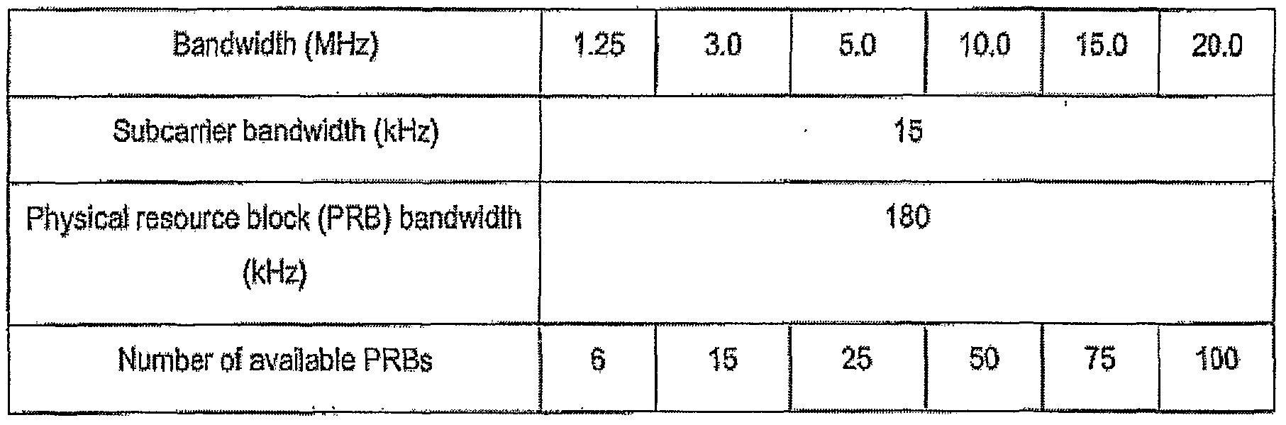
- the total number of available sub-carriers depends on the overall transmission bandwidth of the system.
- the LTE specifications define parameters for system bandwidths from 1.2 MHz to 20 MHz 5 as shown below in Table 1.
- APRB is defined as consisting of 12 consecutive sub-carriers for one slot (0.5 msec) in duration.
- a PRB is the smallest element of resource allocation assignment made by a base station scheduler.
- a transmitted downlink signal consists of NBW sub- carriers for a duration of N sym b OFDM symbols. This can be represented by a resource grid 20 as depicted in FIG. 2. Each box within the grid represents a single sub-carrier for one symbol period and is referred to as a resource element. One such resource element is reference 22 in FIG. 2. In multiple input multiple output applications, there is such a resource grid for each transmitting antenna.
- LTE communication systems do not employ a physical layer preamble to facilitate carrier offset estimates, channel estimation, timing synchronization, etc.
- special reference signals are embedded in the PRBs, as shown in FIG. 3. These reference signals are transmitted during the first and fifth OFDM symbols of each slot when the normal cyclic prefix (CP) is used and during the first and fourth OFDM symbols when the extended CP is used. Reference symbols are transmitted every sixth sub-carrier. Further, reference symbols are staggered in both time and frequency. The channel response on sub-carriers bearing reference symbols • can be computed directly. Interpolation is used to estimate the channel response on the remaining sub-carriers.
- CP normal cyclic prefix
- MIMO multiple-input multiple-output
- LTE Long Term Evolution
- channel impulse responses are determined by sequentially transmitting known reference signals from each transmitting antenna.
- FIG. 4 depicts an exemplary 2x 2 MIMO system including four transceivers 40 to 46, each of which is equipped with a single antenna, respectively referenced 48 to 54. Accordingly, a total of 4 channel impulse responses are provided in this system. While one transmitter antenna is sending a reference signal, the other antenna is idle. Once the channel impulse responses are known, data can be transmitted by both antennas simultaneously. The combination of the two data streams at the two receiver antennas results in a set of two equations and two unknowns, which is resolvable into the two original data streams.
- each transceiver must be able to detect the number of cell-specific transmit antenna ports. Whilst this would otherwise be blindly detected via PBCH demodulation and decoding, the present invention enables a communication device or UE to determine the number of cell-specific transmit antenna ports without PBCH processing.
- the first step required in this process is to generate a downlink reference signal (RS) sequence replica for the maximum possible system bandwidth.
- RS downlink reference signal
- the RS sequence replica is defined by
- n s is the slot number within a radio frame
- / is the OFDM symbol number within the slot
- JV ⁇ DL is the largest downlink bandwidth configuration, expressed in the number of resource blocks (RB).
- the pseudo-random sequence c(i) is defined in Section 7.2 of 3GPP TS 36.211.
- the pseudo-random sequence generator is initialized with at the start of each OFDM symbol where
- data processing block 62 determines downlink system bandwidth from non-coherent correlation, for the first possible transmit antenna port only (that is, transmit antenna port 0), of the generated RS sequence replica and received RS samples at a number of possible bandwidths.
- the non-coherent correlation detection is performed only on the RS transmitted from transmit antenna port 0 as it is the only RS sequence that is guaranteed to exist. It will be understood that at this stage the RS shift, as specified in Section 6.10.1.1 of 3GPP TS 36.211, is already known to the UE as it is derived from the Cell ID obtained from the cell searching process.
- the RS sequence that is actually transmitted from transmit antenna port 0 will vary depending upon the actual downlink system bandwidth, as defined in Section 6 6.10.1.2 of 3GPP TS 36.211.
- the vector of received RS samples at the UE 3 extracted from the received signal samples at receive antenna port 0 of the /* OFDM symbol, given the RS shift described in Section 6.10.1.2 of 3GPP TS 36.211 and assuming the bandwidth is x MHz. denotes the RS offset for transmit antenna port 0.
- the RS offset for transmit antenna port 0. is the vector of received RS samples at the UE 3 extracted from the received signal samples at receive antenna port 0 of the /* OFDM symbol
- the downlink system bandwidth is determined by
- a non-coherent correlation of the received RS samples at the UE and the RS sequence replica generated at the UE is carried out for all possible bandwidths listed in Table 1 above, and the downlink system bandwidth is thereby determined from the greatest calculated correlation value.
- a correlation is performed by data processing block 64 (shown in FIG. 6) of the generated downlink RS sequence replica and received RS samples for all possible transmit antenna ports.
- the correlation C (s, J) is processed by data processing block 66 for all combinations of s and / regarding RS allocation for transmit antenna port 0, 1, 2 and 3, as shown in Section 6.10.11 of 3GPP TS36.211, according to the equation:
- s denotes the RS shift ranged from 0 to 5 as specified in Section 6.10.11 of 3GPP TS 36.211.
- the vector f is the RS sequence calculated in RS pilot pattern generation module given the system bandwidth determined by the processing block 62.
- the vector y ⁇ ⁇ S is obtained by extracting every six samples with the starting offset ,s from the received signal for OFDM symbol / since reference signals are transmitted every sixth subcarrier.
- the number of transmit antenna ports is determined by data processing block 68 from a comparison of the results of the correlations.
- the correlation results comparison is processed based on the following criteria:
- Antenna ports 0 and 1 have the same RS sequence in one OFDM symbol.
- Antenna ports 2 and 3 have the same RS sequence in one OFDM symbol.
- Step 3 If the correlation result of antenna port 1 is much larger than the other 4 positions, a decision can be drawn that antenna port 1 exists. This in turn means at least antenna port 0 and 1 exist. Otherwise, no more process is needed and a decision is drawn that there is only 1 transmit antenna. Step 3:
- N T ⁇ denotes detection result for the number of transmit antennas if detection is successful.
- the present invention can be applied to orthogonal frequency division multiple access (OFDMA) communications system such as the Long Term Evolution (LTE) communication system.
- OFDMA orthogonal frequency division multiple access
- LTE Long Term Evolution
- the present invention can also be applied in particular to the determination by a communication device such as User Equipment (UE) forming part of an LTE communication system of the number of cell-specific antenna ports of the serving cell in communication with the UE.
- UE User Equipment
Landscapes
- Engineering & Computer Science (AREA)
- Signal Processing (AREA)
- Computer Networks & Wireless Communication (AREA)
- Mobile Radio Communication Systems (AREA)
- Radio Transmission System (AREA)
Abstract
Description


Claims
Priority Applications (5)
| Application Number | Priority Date | Filing Date | Title |
|---|---|---|---|
| EP10741305.6A EP2396914A4 (en) | 2009-02-10 | 2010-02-05 | Non-coherent detection method of the number of transmit antenna ports for ofdma |
| CN201080007175.5A CN102308505B (en) | 2009-02-10 | 2010-02-05 | Non-coherent detection method of the number of transmit antenna ports for OFDMA |
| KR1020117018225A KR101229841B1 (en) | 2009-02-10 | 2010-02-05 | Non-coherent detection method of the number of transmit antenna ports for ofdma |
| US13/148,493 US8514803B2 (en) | 2009-02-10 | 2010-02-05 | Non-coherent detection method of the number of transmit antenna ports for OFDMA |
| JP2011548899A JP5488616B2 (en) | 2009-02-10 | 2010-02-05 | Non-coherent detection method and number of communication antenna ports for OFDMA |
Applications Claiming Priority (2)
| Application Number | Priority Date | Filing Date | Title |
|---|---|---|---|
| AU2009900530A AU2009900530A0 (en) | 2009-02-10 | A non-coherent detection method of the number of transmit antenna ports for OFDMA | |
| AU2009900530 | 2009-02-10 |
Publications (1)
| Publication Number | Publication Date |
|---|---|
| WO2010093028A1 true WO2010093028A1 (en) | 2010-08-19 |
Family
ID=42561868
Family Applications (1)
| Application Number | Title | Priority Date | Filing Date |
|---|---|---|---|
| PCT/JP2010/052110 Ceased WO2010093028A1 (en) | 2009-02-10 | 2010-02-05 | Non-coherent detection method of the number of transmit antenna ports for ofdma |
Country Status (6)
| Country | Link |
|---|---|
| US (1) | US8514803B2 (en) |
| EP (1) | EP2396914A4 (en) |
| JP (1) | JP5488616B2 (en) |
| KR (1) | KR101229841B1 (en) |
| CN (1) | CN102308505B (en) |
| WO (1) | WO2010093028A1 (en) |
Cited By (3)
| Publication number | Priority date | Publication date | Assignee | Title |
|---|---|---|---|---|
| CN103209034A (en) * | 2012-01-16 | 2013-07-17 | 晨星软件研发(深圳)有限公司 | Method applied to wireless network receiving end for judging number of transmitting terminal antennas and relative device |
| WO2014112916A1 (en) | 2013-01-17 | 2014-07-24 | Telefonaktiebolaget L M Ericsson (Publ) | Determining signal transmission bandwidth |
| WO2014161087A1 (en) * | 2013-04-02 | 2014-10-09 | Sierra Wireless, Inc. | Method and apparatus for broadcast channel decoding |
Families Citing this family (2)
| Publication number | Priority date | Publication date | Assignee | Title |
|---|---|---|---|---|
| US9344953B2 (en) * | 2009-08-17 | 2016-05-17 | Nokia Technologies Oy | Apparatus and method for initialization and mapping of reference signals in a communication system |
| CN104363037B (en) * | 2014-12-10 | 2017-10-10 | 重庆邮电大学 | A kind of rapid detection system and method for LTE system antenna port number |
Citations (7)
| Publication number | Priority date | Publication date | Assignee | Title |
|---|---|---|---|---|
| JP2006101035A (en) * | 2004-09-28 | 2006-04-13 | Toshiba Corp | Wireless communication device |
| JP2006211727A (en) * | 2006-04-21 | 2006-08-10 | Sanyo Electric Co Ltd | Transmitting method and apparatus thereof |
| JP2006333088A (en) * | 2005-05-26 | 2006-12-07 | Matsushita Electric Ind Co Ltd | Base station apparatus, mobile station apparatus, and radio transmission method |
| JP2007060116A (en) * | 2005-08-23 | 2007-03-08 | Matsushita Electric Ind Co Ltd | Radio terminal apparatus and symbol timing detection method in scalable bandwidth system |
| WO2007135733A1 (en) * | 2006-05-23 | 2007-11-29 | Panasonic Corporation | Radio base station apparatus |
| JP2008017144A (en) * | 2006-07-05 | 2008-01-24 | Toshiba Corp | Radio receiving apparatus and method |
| JP2008118309A (en) * | 2006-11-01 | 2008-05-22 | Ntt Docomo Inc | Cell search method, mobile station and base station |
Family Cites Families (8)
| Publication number | Priority date | Publication date | Assignee | Title |
|---|---|---|---|---|
| US7548506B2 (en) * | 2001-10-17 | 2009-06-16 | Nortel Networks Limited | System access and synchronization methods for MIMO OFDM communications systems and physical layer packet and preamble design |
| US7039370B2 (en) * | 2003-10-16 | 2006-05-02 | Flarion Technologies, Inc. | Methods and apparatus of providing transmit and/or receive diversity with multiple antennas in wireless communication systems |
| US7826807B2 (en) * | 2005-03-09 | 2010-11-02 | Qualcomm Incorporated | Methods and apparatus for antenna control in a wireless terminal |
| US8325826B2 (en) * | 2005-03-09 | 2012-12-04 | Qualcomm Incorporated | Methods and apparatus for transmitting signals facilitating antenna control |
| CN101238668B (en) * | 2005-08-22 | 2011-05-04 | 松下电器产业株式会社 | Base station device and mobile platform device |
| TW200838194A (en) * | 2005-12-21 | 2008-09-16 | Interdigital Tech Corp | Synchronization channel for OFDMA based evolved UTRA downlink |
| ES2706020T3 (en) * | 2006-11-01 | 2019-03-27 | Qualcomm Inc | Reference signal design for cell search in an orthogonal wireless communication system |
| US8295381B2 (en) * | 2008-04-21 | 2012-10-23 | The Regents Of The University Of California | Signal decoder with general purpose calculation engine |
-
2010
- 2010-02-05 WO PCT/JP2010/052110 patent/WO2010093028A1/en not_active Ceased
- 2010-02-05 EP EP10741305.6A patent/EP2396914A4/en not_active Withdrawn
- 2010-02-05 KR KR1020117018225A patent/KR101229841B1/en not_active Expired - Fee Related
- 2010-02-05 CN CN201080007175.5A patent/CN102308505B/en not_active Expired - Fee Related
- 2010-02-05 JP JP2011548899A patent/JP5488616B2/en not_active Expired - Fee Related
- 2010-02-05 US US13/148,493 patent/US8514803B2/en not_active Expired - Fee Related
Patent Citations (7)
| Publication number | Priority date | Publication date | Assignee | Title |
|---|---|---|---|---|
| JP2006101035A (en) * | 2004-09-28 | 2006-04-13 | Toshiba Corp | Wireless communication device |
| JP2006333088A (en) * | 2005-05-26 | 2006-12-07 | Matsushita Electric Ind Co Ltd | Base station apparatus, mobile station apparatus, and radio transmission method |
| JP2007060116A (en) * | 2005-08-23 | 2007-03-08 | Matsushita Electric Ind Co Ltd | Radio terminal apparatus and symbol timing detection method in scalable bandwidth system |
| JP2006211727A (en) * | 2006-04-21 | 2006-08-10 | Sanyo Electric Co Ltd | Transmitting method and apparatus thereof |
| WO2007135733A1 (en) * | 2006-05-23 | 2007-11-29 | Panasonic Corporation | Radio base station apparatus |
| JP2008017144A (en) * | 2006-07-05 | 2008-01-24 | Toshiba Corp | Radio receiving apparatus and method |
| JP2008118309A (en) * | 2006-11-01 | 2008-05-22 | Ntt Docomo Inc | Cell search method, mobile station and base station |
Cited By (7)
| Publication number | Priority date | Publication date | Assignee | Title |
|---|---|---|---|---|
| CN103209034A (en) * | 2012-01-16 | 2013-07-17 | 晨星软件研发(深圳)有限公司 | Method applied to wireless network receiving end for judging number of transmitting terminal antennas and relative device |
| CN103209034B (en) * | 2012-01-16 | 2015-03-18 | 晨星软件研发(深圳)有限公司 | Method applied to wireless network receiving end for judging number of transmitting terminal antennas and relative device |
| WO2014112916A1 (en) | 2013-01-17 | 2014-07-24 | Telefonaktiebolaget L M Ericsson (Publ) | Determining signal transmission bandwidth |
| EP2946499A4 (en) * | 2013-01-17 | 2016-09-21 | Ericsson Telefon Ab L M | Determining signal transmission bandwidth |
| US9722744B2 (en) | 2013-01-17 | 2017-08-01 | Telefonaktiebolaget Lm Ericsson (Publ) | Determining signal transmission bandwidth |
| WO2014161087A1 (en) * | 2013-04-02 | 2014-10-09 | Sierra Wireless, Inc. | Method and apparatus for broadcast channel decoding |
| US9369230B2 (en) | 2013-04-02 | 2016-06-14 | Sierra Wireless, Inc. | Method and apparatus for broadcast channel decoding |
Also Published As
| Publication number | Publication date |
|---|---|
| KR101229841B1 (en) | 2013-02-05 |
| JP2012517731A (en) | 2012-08-02 |
| KR20110104543A (en) | 2011-09-22 |
| JP5488616B2 (en) | 2014-05-14 |
| US20120008576A1 (en) | 2012-01-12 |
| EP2396914A4 (en) | 2015-03-25 |
| US8514803B2 (en) | 2013-08-20 |
| CN102308505A (en) | 2012-01-04 |
| CN102308505B (en) | 2014-07-02 |
| EP2396914A1 (en) | 2011-12-21 |
Similar Documents
| Publication | Publication Date | Title |
|---|---|---|
| KR101105962B1 (en) | Pilot structure with multiplexed unicast and sfn transmissions | |
| EP2052472B1 (en) | Uplink access request in an ofdm communication environment | |
| EP2919538B1 (en) | User equipment, base station device, communication methods and integrated circuits | |
| CN102422663B (en) | Method and apparatus for transmitting positioning reference signal in wireless communication system | |
| US8654734B2 (en) | Multi-cell channel state information-reference symbol patterns for long term evolution extended cyclic prefix and code division multiplexing-time multiplexing | |
| CN103026674B (en) | Use the method, apparatus and system of reference signal in the communications | |
| EP2346188B1 (en) | Method and device for pilot symbol transmission in downlink mimo system | |
| EP1976167A1 (en) | Transmission device, reception device, and communication method | |
| EP2792096A1 (en) | Method for generating and transmitting demodulation reference signals | |
| US8885550B2 (en) | Beacon symbol orthogonalization | |
| US8526321B2 (en) | Method and device for detecting of transmitting antenna configuration in long term evolution system | |
| WO2010068029A2 (en) | Reference signal transmission method for downlink multiple input multiple output system | |
| CN108282289B (en) | Data receiving method and equipment | |
| CN107197422A (en) | The method and its equipment for the signal of direct communication between UE are detected in a wireless communication system | |
| US8514803B2 (en) | Non-coherent detection method of the number of transmit antenna ports for OFDMA | |
| CN107819557B (en) | Transmission processing method, network side device and mobile communication terminal |
Legal Events
| Date | Code | Title | Description |
|---|---|---|---|
| WWE | Wipo information: entry into national phase |
Ref document number: 201080007175.5 Country of ref document: CN |
|
| 121 | Ep: the epo has been informed by wipo that ep was designated in this application |
Ref document number: 10741305 Country of ref document: EP Kind code of ref document: A1 |
|
| ENP | Entry into the national phase |
Ref document number: 20117018225 Country of ref document: KR Kind code of ref document: A |
|
| WWE | Wipo information: entry into national phase |
Ref document number: 2011548899 Country of ref document: JP |
|
| NENP | Non-entry into the national phase |
Ref country code: DE |
|
| WWE | Wipo information: entry into national phase |
Ref document number: 2010741305 Country of ref document: EP |
|
| WWE | Wipo information: entry into national phase |
Ref document number: 6155/CHENP/2011 Country of ref document: IN |
|
| WWE | Wipo information: entry into national phase |
Ref document number: 13148493 Country of ref document: US |