WO2009045148A1 - Method and apparatus for multiple description coding - Google Patents
Method and apparatus for multiple description coding Download PDFInfo
- Publication number
- WO2009045148A1 WO2009045148A1 PCT/SE2008/050355 SE2008050355W WO2009045148A1 WO 2009045148 A1 WO2009045148 A1 WO 2009045148A1 SE 2008050355 W SE2008050355 W SE 2008050355W WO 2009045148 A1 WO2009045148 A1 WO 2009045148A1
- Authority
- WO
- WIPO (PCT)
- Prior art keywords
- bandwidth
- index assignment
- index
- matrix
- transmission condition
- Prior art date
- Legal status (The legal status is an assumption and is not a legal conclusion. Google has not performed a legal analysis and makes no representation as to the accuracy of the status listed.)
- Ceased
Links
Classifications
-
- H—ELECTRICITY
- H03—ELECTRONIC CIRCUITRY
- H03M—CODING; DECODING; CODE CONVERSION IN GENERAL
- H03M7/00—Conversion of a code where information is represented by a given sequence or number of digits to a code where the same, similar or subset of information is represented by a different sequence or number of digits
- H03M7/30—Compression; Expansion; Suppression of unnecessary data, e.g. redundancy reduction
-
- H—ELECTRICITY
- H03—ELECTRONIC CIRCUITRY
- H03M—CODING; DECODING; CODE CONVERSION IN GENERAL
- H03M13/00—Coding, decoding or code conversion, for error detection or error correction; Coding theory basic assumptions; Coding bounds; Error probability evaluation methods; Channel models; Simulation or testing of codes
- H03M13/35—Unequal or adaptive error protection, e.g. by providing a different level of protection according to significance of source information or by adapting the coding according to the change of transmission channel characteristics
- H03M13/353—Adaptation to the channel
-
- H—ELECTRICITY
- H03—ELECTRONIC CIRCUITRY
- H03M—CODING; DECODING; CODE CONVERSION IN GENERAL
- H03M7/00—Conversion of a code where information is represented by a given sequence or number of digits to a code where the same, similar or subset of information is represented by a different sequence or number of digits
- H03M7/30—Compression; Expansion; Suppression of unnecessary data, e.g. redundancy reduction
- H03M7/3057—Distributed Source coding, e.g. Wyner-Ziv, Slepian Wolf
-
- H—ELECTRICITY
- H04—ELECTRIC COMMUNICATION TECHNIQUE
- H04B—TRANSMISSION
- H04B7/00—Radio transmission systems, i.e. using radiation field
- H04B7/02—Diversity systems; Multi-antenna system, i.e. transmission or reception using multiple antennas
- H04B7/04—Diversity systems; Multi-antenna system, i.e. transmission or reception using multiple antennas using two or more spaced independent antennas
- H04B7/06—Diversity systems; Multi-antenna system, i.e. transmission or reception using multiple antennas using two or more spaced independent antennas at the transmitting station
- H04B7/0613—Diversity systems; Multi-antenna system, i.e. transmission or reception using multiple antennas using two or more spaced independent antennas at the transmitting station using simultaneous transmission
- H04B7/0615—Diversity systems; Multi-antenna system, i.e. transmission or reception using multiple antennas using two or more spaced independent antennas at the transmitting station using simultaneous transmission of weighted versions of same signal
- H04B7/0619—Diversity systems; Multi-antenna system, i.e. transmission or reception using multiple antennas using two or more spaced independent antennas at the transmitting station using simultaneous transmission of weighted versions of same signal using feedback from receiving side
- H04B7/0621—Feedback content
- H04B7/0632—Channel quality parameters, e.g. channel quality indicator [CQI]
-
- H—ELECTRICITY
- H04—ELECTRIC COMMUNICATION TECHNIQUE
- H04B—TRANSMISSION
- H04B7/00—Radio transmission systems, i.e. using radiation field
- H04B7/02—Diversity systems; Multi-antenna system, i.e. transmission or reception using multiple antennas
- H04B7/04—Diversity systems; Multi-antenna system, i.e. transmission or reception using multiple antennas using two or more spaced independent antennas
- H04B7/06—Diversity systems; Multi-antenna system, i.e. transmission or reception using multiple antennas using two or more spaced independent antennas at the transmitting station
- H04B7/0613—Diversity systems; Multi-antenna system, i.e. transmission or reception using multiple antennas using two or more spaced independent antennas at the transmitting station using simultaneous transmission
- H04B7/0615—Diversity systems; Multi-antenna system, i.e. transmission or reception using multiple antennas using two or more spaced independent antennas at the transmitting station using simultaneous transmission of weighted versions of same signal
- H04B7/0619—Diversity systems; Multi-antenna system, i.e. transmission or reception using multiple antennas using two or more spaced independent antennas at the transmitting station using simultaneous transmission of weighted versions of same signal using feedback from receiving side
- H04B7/0621—Feedback content
- H04B7/0634—Antenna weights or vector/matrix coefficients
-
- H—ELECTRICITY
- H04—ELECTRIC COMMUNICATION TECHNIQUE
- H04L—TRANSMISSION OF DIGITAL INFORMATION, e.g. TELEGRAPHIC COMMUNICATION
- H04L5/00—Arrangements affording multiple use of the transmission path
- H04L5/003—Arrangements for allocating sub-channels of the transmission path
- H04L5/0053—Allocation of signalling, i.e. of overhead other than pilot signals
- H04L5/0057—Physical resource allocation for CQI
Definitions
- the present invention relates to the field of multiple description coding in a communications system, and in particular to the design of an index assignment matrix to be used for multiple description coding.
- any communications system there is a risk that information that is transmitted from a transmitting end to a receiving end will be lost during transmission.
- diversity is often introduced, so that the information is transmitted over two or more independent channels.
- independent channels can for example be achieved by employing two or more different transmission paths and/or by transmitting the information at two or more different points in time or at different frequencies.
- MDC multiple description coding
- the different descriptions can be chosen to be similar to each other so that redundancy is large, whereas in a scenario where the probability of packet erasure is small, the different descriptions can be chosen to differ from each other to a greater extent, so that redundancy is smaller.
- the method described by Vaishampayan of designing an MDC encoder involves optimisation of an index assignment matrix by way of iteration. Such iterative optimisation of the MDC encoder requires high processing power. A way of designing a feasible index assignment matrix that requires less processing power is desired.
- a problem to which the present invention relates is the problem of how to reduce the processing power required for the design of an index assignment matrix.
- the method is characterised by selecting a bandwidth for the index assignment matrix in dependence of transmission condition information relating to a transmission condition of a communication channel onto which a description of the information signal can be transmitted.
- the problem is further addressed by an apparatus for use in the design of an index assignment matrix to be used in multiple description coding of an information signal, as well as by a computer program product.
- the inventive apparatus comprises a bandwidth selecting unit adapted to generate a signal indicative of a bandwidth of the index assignment matrix.
- the bandwidth selecting unit has an input adapted to receive transmission condition information indicative of a transmission condition on a communication channel onto which a description of the information signal can be transmitted.
- the bandwidth selecting unit is furthermore adapted to generate the signal indicative of the bandwidth in dependence of the transmission condition information.
- the bandwidth selecting unit moreover has an output adapted to output the signal indicative of the bandwidth.
- the bandwidth of an index assignment matrix is a measure of the band of the matrix, and can, for a square matrix in the two-dimensional case, be defined as the number of adjacent diagonals to which the non-zero elements of the matrix are confined.
- a similar definition of the bandwidth can be made for a non-square matrix, in two or more dimensions. Alternative definitions of the bandwidth may also be used.
- the design of the index assignment matrix can be performed according to an index assignment algorithm, which could for example be a prior art index assignment algorithm.
- an index assignment matrix used for encryption (or decryption) onto a transmission interface can be redesigned at low processing cost.
- the optimal design of an index assignment matrix of an encoder or decoder operation according to multiple description coding depends on the transmission conditions in which the encoder is operating. Since transmission conditions in most communications systems vary over time, it is desirable to enable adjustment of the index assignment matrix to such varying transmission conditions in an on-line fashion. By the low-processing-cost inventive method and apparatus, such on-line adjustment to transmission conditions may efficiently be performed.
- the selecting of a bandwidth comprises determining a root of a polynomial, wherein the coefficients of the polynomial are defined in dependence of the transmission condition information. Since finding a root of a polynomial only requires a few processing steps, this embodiment is processing power efficient.
- the selecting of a bandwidth comprises accessing a memory in which is stored information corresponding to a table over possible values of a transmission condition and corresponding suitable bandwidth values.
- the selecting of a bandwidth further comprises comparing the transmission condition information for which a bandwidth is to be selected to the possible values of the transmission condition stored in the memory; and selecting the bandwidth in accordance with the information stored in the memory.
- the invention may for example be applied in encoders and/or decoders of varying communications systems.
- transmission condition information could advantageously be received from a node in the communications system.
- the invention may also be applied in an apparatus for determining suitable bandwidths of index assignment matrices for multiple description coding at different transmission conditions.
- Fig. 1 is a schematic illustration of a communications system wherein diversity is employed.
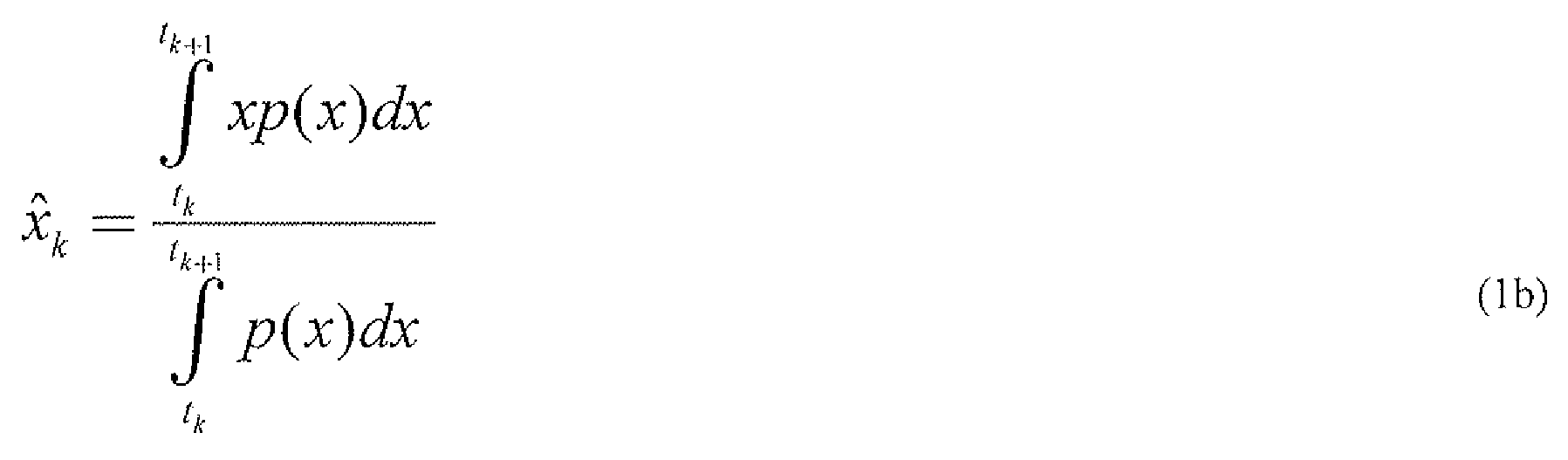
- Fig. 2 schematically illustrates an encoder and a decoder operating according to a multiple description coding using two different descriptions of an information signal x.
- Fig, 3a illustrates the mapping performed by an exemplary central quantizer.
- Fig. 3b illustrates the mapping performed by a resolution constrained central quantizer.
- Fig. 3c illustrates the mapping performed by an entropy constrained central quantizer.
- Fig. 4 illustrates an example of an index assignment matrix
- Fig. 5 schematically illustrates a method according to the invention.
- Fig. 6a illustrates an embodiment of one of the steps of the method of Fig. 5 in more detail.
- Fig. 6b illustrates an embodiment of one of the steps of the method of Fig. 5 in more detail.
- Fig. 6c illustrates an embodiment of one of the steps of the method of Fig. 5 in more detail.
- Fig. 7 schematically illustrates an apparatus comprising a bandwidth selecting unit.
- Fig. 8a schematically illustrates an embodiment of a bandwidth selecting unit.
- Fig. 8b schematically illustrates an embodiment of a bandwidth selection unit.
- Fig. 9 schematically illustrates an apparatus comprising a bandwidth selecting unit connected to a matrix design unit for designing an index assignment matrix.
- Fig. 10 shows an example of an index assignment matrix (left) for nested index assignment and corresponding side cell patterns (right).
- a communication system 100 comprising a first communication node 105 and a second communication node 110 is schematically illustrated in Fig. 1.
- First communication node 105 and second communication node 110 can communicate with each other over an interface 115 which employs diversity.
- Interface 115 could have any n>l communication channels 120 - in Fig. 1, interface 115 is shown to comprise three different communication channels 120 ⁇ ) .
- Both first and second communication nodes 105 and 110 could typically act as both a receiving node and a transmitting node.
- first communication node 105 will in the following be described as a transmitting node 105
- second communication node 110 will in the
- Transmitting node 105 comprises an encoder 125 and receiving node 1 10 comprises a decoder 130.
- any number of descriptions can be used by a system operating accoiding to multiple description coding.
- the invention will in the following be described in terms of a system using two different descriptions transmitted over two different communication channels 120. Furthermore, the description will mainly focus on the symmetrical case, where the number of possible values onto which the information signal can be mapped is the same for both descriptions, as is the probability of erasure, w. It should however be understood that the invention may be generalised to any number of descriptions of an information signal, as well as to a nonsymmetrical case.
- the encoder 125 and a decoder 130 operating according to a multiple description coding using two different descriptions of an information signal x is schematically illustrated in Fig. 2.
- the encoder 125 of Fig. 2 has an input 200 for receiving an information signal x having a probability density function /;(x ⁇ )
- the encoder 125 further has a central quantizer 205, arranged to map a sample of the information signal x onto a central quantizer index k, where k e ⁇ l,.,,,,r ⁇ 3 and r is the number of central quantizer cells, i.e. the number of quantization levels of the central quantizer 205.
- the mapping of the central quantize]- 205 is denoted a 0 (x) .
- FIG. 3a The mapping performed by an exemplary central quantizer 205 is illustrated in Fig. 3a.
- Possible values of the scalar source represented by the information signal x to be quantised are shown along an axis 305 in Fig. 3a.
- the central quantizer 205 described by Fig. 3a has r cells 300.
- Each central quantizer cell 300 is indexed k and has cell boundaries ⁇ i k / ⁇ 1 ) along the axis 305, where k is an integer value between 1 and r, and t is a vector of cell boundaries.
- a central quantizer cell 300 ⁇ represents the possible values of the information signal x which the central quantizer will map onto the central quantizer index /c.
- the length ⁇ / ⁇ of the A 1 ' 1 central quantizer cell 300 ⁇ is ⁇ , ⁇ t k l ] - t k .
- the length ⁇ / ⁇ is often referred to as the extent ⁇ /f of the cell 300 ⁇ .
- Each central quantizer cell 300 has an associated reconstruction point , where is a real number.
- the reconstruction point corresponds to the value which will be used by a decoder 130 to reconstruct a corresponding sample of x upon receipt of the central quantizer index k, and will in the following be referred to as a central reconstruction point .
- a central quantizer 205 typically operates under a constraint on either entropy or resolution.
- the resolution of a central quantizer 205 is constrained if the number of central reconstruction points is constraint.
- all central quantizer cell 205 have the same probability, and the same number of bits are used to encode each central quantizer index k.
- a resolution constrained quantizer operates at a fixed rate.
- the condition on equal probability can be achieved by using a variable cell extent along the real axis 305 representing the values of the information signal x to be quantised.
- Resolution constrained central quantizer 205 can for example advantageously be used for delay-sensitive communication services.
- the entropy of a central quantizer 205 is constrained if an average rate R uwmge is fixed. Hence, the momentary rate J? may vary with time, as long as the average rate R avm ⁇ g!1 over a specified time is fixed (the entropy constrained central quantizer generally requires a buffer, and the specified time depends on the size of the buffer).
- the extent A of all quantization cells 300 is the same. This implies that for the common situation where the information signal x to be quantized has a nonuniform probability density function, the probability will vary between different central quantizer cells 300.
- Entropy constrained central quantizers 205 are typically used in communication services for which a certain delay is acceptable.
- the mapping of a resolution constrained central quantizer 205 is schematically illustrated in Fig. 3b, where the different central quantizer cells 300 are of different extents A ⁇ , and the probability /7 of the value of information signal x to fall within the different central quantizer cells 300 is constant.
- the length b of the code word describing an index /c is the same for each cell.
- the mapping of an entropy constrained quantizer 205 is illustrated in Fig. 3c, wherein different central quantizer cells 300 are of the same extent A, and the probability /? A of the value of the information signal x to fall within a quantizer cell 300 ⁇ varies between different quantizer cells 300.
- the length b k of a code word describing an index k varies between different cells 300, where the length b k is smaller for code words k having a higher probability.
- the central quantizer 205 illustrated in Fig. 3 is an entropy constrained quantizer which is optimal in the high rate sense, i.e., the central reconstruction points x k lie in the middle of each cell 300:
- a central reconstruction point x k can be computed by using weighting with the source probability density function /?foj, i.e:
- the encoder 125 of Fig. 2 further comprises two side coders 210 (i) and 210 (2) , which are both arranged to receive the central quantizer output, i.e. the central quantizer indices k e ⁇ l,....,r ⁇ obtained by the mapping a Q (x) .
- Side coder 210 (l) hereinafter referred to as first side coder 210 (i) , is arranged to map an index k from the central quantizer 205 onto a First side coder cell index Zc 1 .
- Second side coder 210 (2) is arranged to map the index k from the central quantizer 205 onto a second side coder cell index Ii 2 . These mappings are referred to as ⁇ , (k) and a 2 (k) , respectively.
- the number of cells in first side coder 210 (1) is denoted M 1
- the number of cells in second side coder 210 (2) is denoted M 2 .
- the first side coder 210 (l) when a central quantizer index k is received by the first side coder 210 (l) , the first side coder 210 (l) will map this index k onto a first side coder cell index k ⁇ e (1,....,M 1 ⁇ , while if the same central quantizer index k is received by the second side coder 210 (2) , the second side coder 210 (2) will map this index k onto a second side coder cell index. k 2 e ⁇ l,...., M 2 ) .
- the invention is equally applicable to multiple description coding wherein
- the mappings a x (k) and a 2 (k) can be illustrated by way of a matrix, which in the following will be referred to as the index assignment matrix 400 (in the n- dimensional case, where the information signal x is encoded into n different descriptions which are transmitted over the interface 1 15, the index assignment matrix 400 will be an n- dimensionai matrix).
- the number of central quantizer indices k is 44, i.e. r - 44
- a side coder cell is generally denoted , where / is the side coder identity and / represents a value of the side coder cell index Ic 1 .
- the first side coder cell having index 4 i.e. , has been marked in bold, and corresponds to the set ⁇ 12, 13, 14, 16, 22 ⁇ .
- the mapping of a central quantizer index k onto a first and second side coder cell index /c, and Ic 2 will yield a side coder cell index pair ( k ] , k 2 ).
- a side coder cell index pair uniquely defines a central quantizer index k.
- the side coder cell index pair (4, 5) of Fig. 4 uniquely defines the central quantizer index 16.
- the mappings a t (Ic) and a t (k) of the central quantizer indices k can be made in a number of different ways. Different ways of filling the index assignment matrix 400 give rise to different distortions of the decoded information signal x on the decoder side of the interface 115, as will be further discussed below.
- the index assignment matrix 400 of Fig. 4 has been generated by means of the herringbone index assignment algorithm.
- the base rate R hme will change, the base rate being the rate at which pure information is transmitted:
- R is the total rate and R rechmdancy is the part of the total rate R which is used for transmission of redundant information.
- the first and second side coders 210 (1) and 210 (2) are each connected to an output 215 ⁇ , referred to as output 215 ⁇ and 215 (2) , respectively.
- the outputs 21 5 (1) and 215 (2) arc illustrated in Fig. 2 to be two separate outputs, the outputs 215 (1) and 215 (2) may alternatively use the same physical output 215 (different logical outputs 215 (1 ⁇ and 215 (2) could then for example be achieved by employing transmission from the same physical output 215 at different times, or at different frequencies)
- Outputs 215 (!) and 215 (2) are arranged to transmit the indices /c, and k 2 , respectively, to the encoder
- the decoder 130 of Fig. 2 has two different inputs 220 (! and 220 (2) , arranged to receive signals from the first and second side coders 210 (! and 210 (2) , respectively, and to retrieve the first and second side coder indices £, and k 2 , respectively. As with outputs
- the decoder 130 further comprises a central decoder 225, as well as a first side decoder 230 (1) and a second side decoder 230 (2; ⁇ .
- Input 220 (!) is arranged to convey any received first side coder cell index /c, to the first side decoder 230 1 ⁇ as well as to a central decoder 225, whereas the second input 220 (z: ⁇ is arranged to convey any received second side coder indices k 2 to the second side decoder 230 ⁇ as well as to the central decoder 225.
- Central decoder 225 is arranged to perform a mapping of the index pair (Zc 1 , Ic 2 ) onto a central quantizer index /c. Typically > the central decoder 225 is further arranged to determine the central quantizer reconstruction point x k (cf. expressions (Ia) and (I b)), and to output a signal indicative of the reconstruction point x k onto a central decoder output 235 ⁇ to which the central decoder 225 is connected.
- the mapping performed by the central decoder 225 in order to determine the reconstruction point x k from the central quantizer index k is denoted /? 0 (Zc 1 Jc 2 ) .
- the side decoders 230 ⁇ are
- a side coder reconstruction point from the received side coder cell index k p and to deliver a signal indicative of the side coder reconstruction point .
- First side decoder 235 (1) is connected to a first side coder output 235 1 ⁇ and second side coder 235 ⁇ is connected to a second side coder output 235 ⁇ (The outputs 235 may use the same, or different, physical outputs).
- each side coder 210 could advantageously be connected to an entropy coder, which in turn would be connected to one of the outputs 215.
- the decoder 230 would then advantageously comprise two entropy decoders, each connected to an input 220 Cl> and arranged to retrieve a side coder cell index k ⁇ .
- the encoder 125 and decoder 130 of Fig. 2 are adapted to multiple description encoding/decoding using two different descriptions.
- an encoder 125 would include n side coders 120.
- ⁇ decoder 130 would preferably include (2" - 1) decoders 225/230, since there should preferably be one decoder for each possible description subset that may be received.
- the central decoder 225 can retrieve the central quantizer index k corresponding to the side coder cell index pair (Zr 1 , k 2 ) by use of the applicable index assignment matrix 400. From the value of the retrieved central quantizer index k, a central reconstruction point can be obtained as the corresponding value of the information signal x (cf. Fig. 3a).
- Disturbances generally occur, more or less frequently, on a transmission interface 1 15, and the probability of erasure, w, on an interface 1 15 is generally non-zero.
- the central quantizer index k corresponding to the side coder cell index pair (A 1 , k 0 ) can generally not be uniquely determined.
- information about the value of the information signal x can still be obtained via the applicable index assignment matrix 400.
- index k falls within this set.
- the side coder reconstruction point falls outside this set, but within the extent of the side coder cell
- a side coder cell is typically not a continuous interval but includes of a set of disjoint intervals.
- the side coder cell extent can
- the side coder cell extent is sometimes referred to as the diameter of the side coder cell.
- an estimated value of the information signal x represented by the side coder cell index pair can be obtained from the side coder reconstruction point, which may be determined as follows:
- y is the side coder identity and / is a value of the received side coder cell index k s of the pair.
- the number of quantizer cells 300 will be M x M .
- the base rate R baw will in this case be at its highest. Redundancy, on the other hand, will be at its lowest (zero) when the index assignment matrix 400 is completely filled. If only one of the side coder cell indices k i and k 2 is received by the decoder 130, the uncertainty of which central quantizer index k gave rise to the received side coder cell index k ⁇ will in this situation be high, since the number of central quantizer indices k in a side coder cell will take its greatest value, i.e.
- the redundancy and the resolution/entropy of the encoder 125 both affect the distortion of the information signal * as received by the decoder 130.
- high base rate high resolution/high entropy
- the stability of a communication channel 120 generally varies significantly with time, and the possibility of adjusting the trade-off between redundancy and base rate to the current transmission conditions would therefore be highly desirable.
- State-of-the-art methods of designing an index assignment matrix are based on iteration, where a large number of iterations are required before convergence. High processing powers are therefore required for such methods.
- These index assignment matrix design methods are therefore generally not suitable for online adjustment of an index assignment matrix to current transmission conditions.
- An index assignment matrix 400 is generally a band matrix, whose non-zero entries are confined to a diagonal band, wherein the diagonal band comprises a main diagonal and possibly further diagonals on either side of the main diagonal.
- the trade-off between redundancy and base rate R hme can be optimised for certain transmission conditions by means of an analytical function describing the side coder distortion d / of an information signal x as a function of the bandwidth v of an index assignment matrix 400 to be used for the transmission of the information signal x.
- the bandwidth of an index assignment matrix is a measure of the band of the matrix, and can, for a square matrix in the two-dimensional case, be defined as the number of adjacent diagonals to which the non-zero elements of the matrix are confined.
- a similar definition of the bandwidth v can be made for a non-square matrix, in two or more dimensions.
- the bandwidth of the index assignment matrix 400 could advantageously be expressed by means of an M-dimensional vector v, where n is the number of descriptions employed in the multiple description coding.
- a vector component v ; , /M . , ,??, is an integer describing the bandwidth v ) of the index assignment matrix 400 in the/th dimension.
- the bandwidth v can alternatively be defined as the number of central quantizer indices k in a typical side coder cell of the index assignment matrix 400, where a "typical" side coder cell refers to a side coder cell at a sufficient distance from the matrix boundaries ("corners"). In other words, the bandwidth v represents the number of non-zero 1 centra!
- the linear index assignment algorithm may generate elements within the band that take the value zero. For purposes of determining the bandwidth v, such elements should be counted as non-zero elements.
- the bandwidth v describes the number of diagonals in the band of the index assignment matrix 400.
- bandwidth v of the index assignment matrix 400 may be used.
- Optimisation problems relating to the trade-off between redundancy and base rate R ki!!e in multiple description coding in different scenarios can be solved by means of an analytical function of the side coder distortion d ⁇ at a very small processing power cost.
- Such scenarios could for example be A) minimisation of the composite distortion d t subject to a constraint on the entropy of side coder cell indices k for a particular probability of erasure w .
- Such information typically relate to the quality of the channel onto which the information signal x is to be transmitted, and can for example relate to the probability of erasure w (scenario A & B) on a transmission channel 120; to the average rate available on a transmission channel 120® for transmission by a side coder side 210® (a constraint on the entropy can be seen as a constraint on the average rate R tmmg ⁇ ; ) (scenario A & C); or to the fixed rate available on a transmission channel 12(/ for transmission by a side coder 210® (a constraint on the resolution of a side coder 120, i.e. a constraint on the number of side coder cells, M, can be seen as a constraint on the available fixed bit rate on the transmission channel 120 ⁇ ) (scenario B & D).
- the composite distortion d t is a weighted function of the central distortion d 0 and the side coder distortions d l (weighted for instance by the probability of erasure, see expression (4) below).
- the side coder distortion can be expressed in terms of a measure of the band of an optimal index assignment matrix.
- the composite distortion d t is a sum of all possible distortions resulting from all possible subsets of descriptions that may be received at the receiver, weighted by the probabilities of receiving each particular subset.
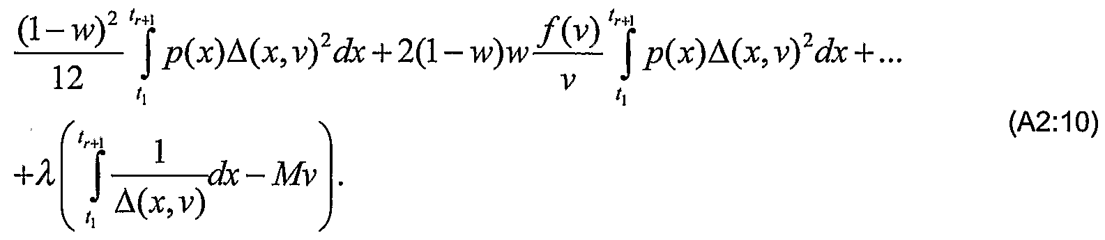
- the composite distortion d t can be expressed as (using squared error criterion):
- the factor (1 - w) 2 corresponds to the probability of both side coder cell indices (A 1 , /c, ) arriving safely at the decoder 130 and 2(1 - w)w corresponds to the probability that only one side coder cell index k f arrives safely.
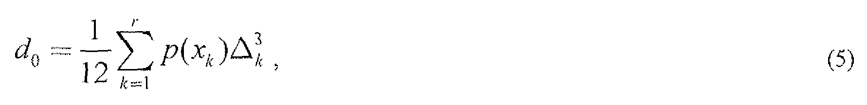
- p(x k ) is the source probability density function evaluated at the central reconstruction point x k and ⁇ / ⁇ is the extent of the central quantizer cell 300 ⁇ .
- A(x) is a function describing the value of the central quantizer cell extent if the reconstruction point had been given the value x.
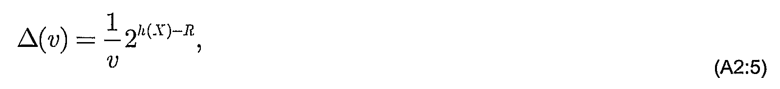
- ⁇ (x) which can be referred to as the step size, is a function inversely proportional to the local density of the reconstruction points (centroids) x per unit length.
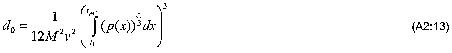
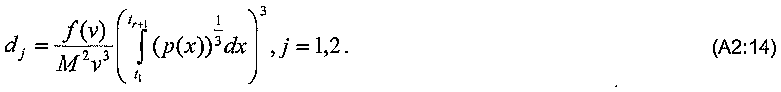
- Expression (6) is an analytical function by means of which values of the central distortion can easily be calculated.
- the probability density function of the source can be approximated as constant within a side coder cell extent of the index assignment matrix.
- This assumption can alternatively be expressed as the assumption that the central quantizer cell extent ⁇ is approximately constant within the side coder cell extent, and will be referred to as a high rate assumption.
- the pattern of central quantizer indices k within a side coder ceil of the index assignment matrix 400 is one of a set of possible patterns, and that the pattern of indices of different side coder cells is ordered within the index assignment matrix 400.
- Assumption 2 is made for purposes of estimating the side coder distortion. However, for other purposes, such as for mapping the central quantizer indices k onto the index assignment matrix 400, this assumption would generally not be used.
- a special case of assumption 2) is to assume, for purposes of estimating the side coder distortion, that the pattern of indices within a side coder cell extent is constant for a particular side coder 210. In order to simplify the des ⁇ iption, this special case is the case which will be considered below.
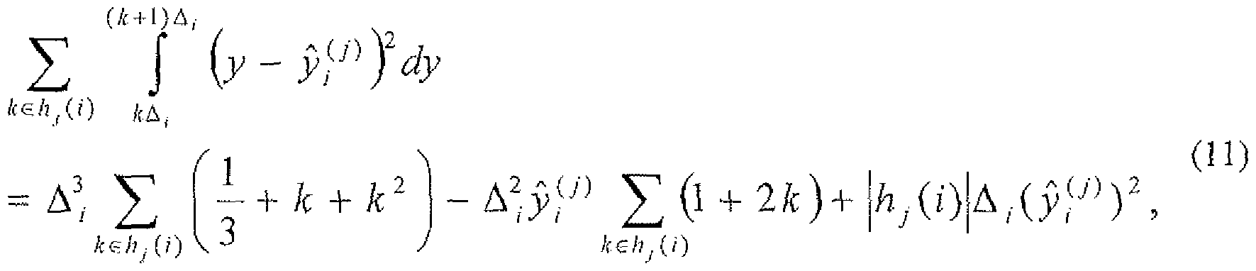
- the side coder distortion d f of side coder 210 ⁇ is given by:
- expression (7) can be expressed as:
- ⁇ is the extent of the central quantizer cells 300 within the side coder cell
- the distortion of a single side coder cell can be expressed as:
- h / (/) is the cardinality of the set , i.e. number of non-zero indices in the side coder cell
- a value of the corresponding side coder reconstruction point can be obtained via (see above).
- v Is the bandwidth of the index assignment matrix 400.
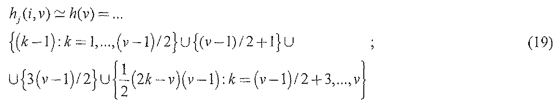
- Adopting assumption 2 As can be noted in expression (15), the coefficient of quantisation depends on the side coder cell index / (that is, k f ), since the normalised pattern of indices generally varies from one side coder cell to another side coder cell within the index assignment matrix 400. This dependency complicates the calculation of the side coder distortion d , when the number M of side coder cells is large. However, we have noted that the dependency of the side coder cell index / can be neglected for purposes of estimating the side coder distortion d f and thus that the normalised pattern of indices within a side coder cell extent of the index assignment matrix 400 can be approximated as constant within the same side coder 210 ⁇ . For a symmetrical case, the pattern of indices does not depend on the side quantizer index/. Hence, the normalised pattern of indices can be replaced in expression (15) by an /-independent pattern of indices, h(y) .
- h(v) is a typical pattern of an index assignment matrix 400, which pattern depends on the matrix bandwidth v and differs between different index assignment algorithms. h(v) approximates the geometry of the side coder cells for a given bandwidth v, and will in the following be referred to as an average pattern of indices.
- the average pattern of indices h(v) depends on the bandwidth v of the index assignment matrix 400.
- An average pattern of indices h(v) is given below for a number of different index assignment algorithms, see expressions (19) - (22).
- ⁇ (x,v) is a function describing the central quantizer cell extent ⁇ k if the reconstruction point had been given the value x in an index assignment matrix 400 having bandwidth v
- ⁇ ( ⁇ ,v) is inversely proportional to the local density of the reconstruction points (centroids) x per unit length for given bandwidth can be considered a coefficient of quantisation:
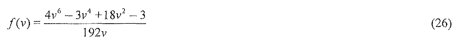
- an analytic expression for the side coder distortion d f is obtained which depends on the bandwidth v.
- This expression may be used in an optimisation scenario, in combination with the analytical expression for the central distortion d 0 given by expression (6), in order to obtain an optimal value of v under certain transmission conditions and constraints.
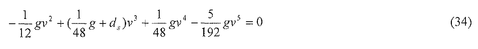
- the analytical functions of the side coder distortions d and the central coder distortions d 0 can advantageously be used to derive a solution to a given design problem, wherein the solution is expressed in terms of a polynomial rooting resulting in a polynomial of which the real and positive roots can be rounded or truncated to an integer which corresponds to a value of the bandwidth v of the index assignment matrix 400.
- a value of the bandwidth v of the index assignment matrix 400 can be derived from a real and positive root of one of the polynomials (28)-(31), where the root would be rounded or truncated to an integer which corresponds to the bandwidth v.
- the probability of erasure w should, in the polynomials (28)-(31), be expressed as the probability of erasure of a side coder cell index K 1 of one of the descriptions.
- other ways of expressing the probability of erasure w over a communication channel 120 may be used when expressing the transmission conditions, such as the probability of erasure of a data packet transmitted over the communications channel 120.
- Such alternative expressions of the probability of erasure w can easily be converted into the probability of erasure of a side coder cell index Ic 1 for purposes of determining the coefficients of the polynomials (28)-(31).
- the optimisation scenario A) is typically interesting in systems where a certain transmission delay is acceptable and where the encoder 125 comprises a buffer, which is used in the adaptation of a varying bit rate of the central quantizer 205 and/or side coders 210 ⁇ into a fixed bit rate available on the transmission channel 120 ⁇ .
- Optimisation scenario B) is typically interesting in systems wherein a side coder 210 has a limited number of quantization levels, and where the probability of erasure w is known or can be estimated,
- a value of the bandwidth v of the index assignment matrix 400 can be derived from a real and positive root of one of the polynomials (32)- (35), for a certain maximum side coder distortion d ⁇ .
- the root would be rounded or truncated to an integer which corresponds to the bandwidth v.
- Optimisation scenario C) is typically interesting when the entropy of the side coders 210 is constrained and there is a requirement on the quality of the reconstruction for the case when only one of the descriptions is received, i.e. when a too coarse reconstruction is undesirable.
- an encoder/decoder can be designed which provides a guaranteed minimum quality when only one description is received.
- An optimal value of the number of side coder cells, M depends on the available fixed bit rate on the transmission channels 120® over which the side coder indices k j are to be transmitted.
- a constraint on the number of side coder cells, M can be seen as a constraint on the available fixed bit rate on the transmission channel 120®.
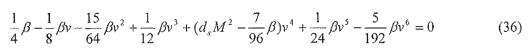
- a value of the bandwidth v of the index assignment matrix 400 can be derived from a real and positive root of one of the polynomials (36)-(39), for a certain maximum side coder distortion d ⁇ . If not already an integer, the root would have to be rounded or truncated to an integer which corresponds to the bandwidth v.
- Optimisation scenario D is typically interesting when the resolution of the side coders 230 is constrained and there is a requirement on the quality of the reconstruction for the case when only one of the descriptions is received, i.e. when a too coarse reconstruction is undesirable.
- an encoder/decoder can be designed which provides a guaranteed minimum quality when only one description is received.
- the particular index assignment algorithm puts further constraints on the bandwidth v - typically that the bandwidth v be either even or odd.
- the truncating or rounding should advantageously take such further constraints into account.
- the indication that the bandwidth v should equal 1 could result in that a special index assignment algorithm is applied which results in only one non-zero element in each column or row (full redundancy).
- a suitable value of the bandwidth v could be selected for the index assignment algorithm to be applied (preferably the lowest value of v that is applicable to the particular index assignment algorithm).
- Fig. 5 schematically illustrates a method for designing an index assignment matrix according to the invention.
- transmission condition information is received.
- the transmission condition information can advantageously be received from another node in the communications network or from a transmission condition determination unit in the node.
- the transmission condition information can for example be received from a memory, from an external source, or from an internal process.
- a bandwidth v of the index assignment matrix 400 to be designed is selected in dependence of transmission condition information relating to transmission conditions on a channel 120 O) over which an information signal x, to be encoded by means of the index assignment matrix 400, is to be transmitted.
- transmission condition information could for example include information on the probability of erasure w; available average bitratc R ave ⁇ agc ; available fixed bitrate R ⁇ ; constraints on the side coder distortion ⁇ s or constraints on the central distortion d 0 .
- the transmission condition information could for example have been received by a network node or an Operation and Management node in a communications system 100 and be based on the current situation in the communications system 100, or could for example have been derived from previous experience.
- step 505 is entered, in which an index assignment matrix 400 having the selected bandwidth v is designed according to known algorithms: If the number M 1 of side coder cells of a side coder 210 ⁇ is known, the number r of central quantizer cells 300 can be determined from the bandwidth v, and vice versa. The r central quantizer indices k can then be distributed within the index assignment matrix according to a selected index assignment algorithm. The central reconstruction points as well as the side coder reconstruction points can be determined as described above.
- step 503 of selecting the bandwidth v is illustrated in more detail in Fig. 6a.
- step 503 comprises steps 600- 615.
- step 600 it is assumed, for purposes of determining the side coder distortion d j , that the pattern of indices in a side coder cell is approximately constant in the index assignment matrix 400, i.e. that the pattern of indices is approximately independent of the value / of the side coder cell index Ic 1 (cf. expressions (19)-(22)).
- step 605 the high rate approximation is assumed, i.e.
- step 610 an analytical expression for the side coder distortion d j is determined under the assumptions made in steps 600 and 605 (cf. expression (17)).
- step 615 a bandwidth v of the index assignment matrix 400 that is favourable for a particular optimisation scenario is selected, using the analytical expression of the side coder distortion d and the transmission condition information (cf. expressions (28)-(39)).
- step 600 of Fig. 6a it is assumed, for purposes of estimating the side coder distortion d t , that the pattern of central quantizer indices k within a side coder cell is constant within the index assignment matrix 400. This is a special case of assumption 2) above.
- the general case would be that it is assumed that the pattern of central quantizer indices k within a side coder cell of the index assignment matrix 400 is one of a set of possible patterns, and that the pattern of indices of different side coder cells is ordered within the index assignment matrix 400.
- Fig. 6a reference is made to both the general and the specific case of step 600.
- Fig. 6a illustrates some inventive assumptions made to multiple description encoding theory that have proven to simplify the of index assignment matrix design in that a suitable or optimal value of the bandwidth v may be obtained by means of an analytical function. Other ways of obtaining an analytical function of the side coder distortion may also be conceived.
- Fig. 6b illustrates a method of solving an analytical function, in this case a polynomial, in order to arrive at a suitable or optimal bandwidth v.
- Fig. 6b illustrates an embodiment of step 503 of Fig. 5.
- Fig. 6b comprises steps 620-630.
- step 620 a polynomial to be used for selecting a suitable bandwidth v is determined in dependence of transmission condition information, cf. for example expressions (28)-(39).
- the polynomials of expression (28)-(39) have all been derived by using the method of steps 600-610 of Fig. 6.
- Other suitable polynomials could alternatively be used.
- a feasible root of the polynomial determined in step 620 is determined, where a feasible root is a root that is real and positive, and preferably greater than 1. From this feasible root, a bandwidth v is selected in step 630.
- the bandwidth v is given the truncated or rounded value of the root determined in step 625.
- the index assignment algorithm to be employed in the index assignment matrix design may put restrictions on the bandwidth v, and the selection of step 630 could then advantageously take such restrictions into account.
- the embodiment of selecting the bandwidth v illustrated in Figs. 6a and 6b could be performed in a transmitting node 105 and/or receiving node HO in an on-line fashion. Transmission condition information reflecting the current transmission conditions could then advantageously be received by the transmitting/receiving node from another network node in a communications system 100. Alternatively, selection according to the method of Fig.
- step 503 of the method illustrated in Fig. 5 would be performed in the transmitting/receiving node 105/1 10 by looking up a suitable bandwidth v for given transmission conditions. This is illustrated in Fig, 6c.
- Step 503 of Fig. 5 as illustrated in Fig. 6c comprises steps 635-645.
- step 635 stored values of transmission conditions with associated suitable bandwidths v are accessed.
- step 640 the value of the transmission condition for which a suitable bandwidth is to be selected is compared to the stored values of the transmission conditions.
- step 645 the bandwidth v which is associated with the stored transmission condition that has provided the best match in the comparison is selected as a suitable bandwidth v.
- Different tables/storages could be used for different optimisation scenarios and/or different index assignment algorithms, wherein the different values stored in the tables/storages would have been obtained from different polynomials.
- a predetermined index assignment algorithm could be used in step 505 for the design of the index assignment matrix 400 (e.g. the linear algorithm, the nested algorithm, etc.).
- a predetermined polynomial corresponding to the predetermined index assignment algorithm would preferably be used for obtaining a value of v (for example one of the polynomials given by expressions (28)- (39)).
- the index assignment matrix 400 would then be designed according to the predetermined index assignment algorithm, having a bandwidth v obtained from the predetermined polynomial .
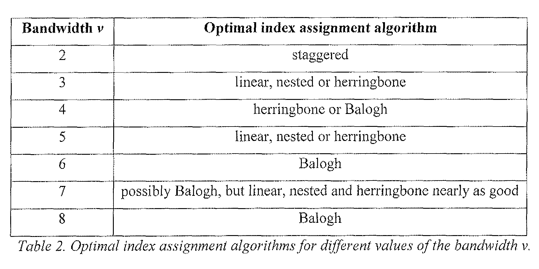
- the index assignment algorithm to be used could depend on the transmission conditions. It turns out that the optimal index assignment algorithm depends on the transmission conditions, and in particular, the optimal index assignment algorithm depends on the value of the bandwidth v. In table 2, the optimal index assignment algorithm is listed for different values of the bandwidth v.
- a predetermined polynomial could be used for the particular optimisation problem of interest, and the optimal index assignment algorithm for the obtained value of the bandwidth v could then be selected in accordance with table 2.
- various polynomials could be solved, each polynomial relating to an index assignment algorithm and being relevant to the optimisation problem of interest.
- the index assignment algo ⁇ thm for which the corresponding polynomial gives the lowest value of v could then be selected as the index assignment algorithm to be used for designing the index assignment matrix 400. If more than one polynomial/index assignment algorithm yield the lowest value of v, the index assignment algorithm that is preferred for the given value of the bandwidth v could advantageously be selected for the design of the index assignment matrix 400 (cf Table 2).
- Fig. 7 is a schematic illustration of an apparatus 700 comprising a bandwidth selecting unit 705.
- the apparatus 700 could for example be an encoder, a decoder, a user equipment comprising an encoder or decodei, a network node comprising an encoder or decoder, or a bandwidth calculation device adapted to calculate the optimal bandwidth v of an index assignment matrix 400 for different transmission conditions.
- the bandwidth selecting unit 705 is adapted to select a suitable bandwidth for an index assignment matrix 400 under particular transmission conditions.
- Bandwidth selecting unit 705 comprises an input 710 adapted to receive a signal 720 indicative of liansmission condition information, and an output 715 adapted to output a signal 725 indicative of a suitable bandwidth v.
- Fig. 8a illustrates an embodiment of the bandwidth selecting unit 705.
- the bandwidth selecting unit 705 of Fig. 8a comprises a polynomial generating unit 800, a root determination unit 805, and an output signal generating unit 810.
- the polynomial generating unit 800 is connected to the input 710, and is adapted to receive the signal 720 indicative of transmission condition information. Furthermore, the polynomial generating unit 800 is arranged to generate, based on the received transmission condition information, a polynomial thai would be suitable for bandwidth selection. Such polynomial could for example be derived from one of the expressions (28)-(39).
- the polynomial generating unit 800 would be adapted to generate more than polynomial based on the transmission condition information, such as for example more than one polynomial relating to the same optimisation scenario but different index assignment algorithms, or more than one polynomial relating to the same index assignment algorithms, but different optimisation scenarios, or any set of polynomials.
- the polynomial generating unit 800 is furthermore preferably adapted to output a signal indicative of the polynomiai(s) generated by the polynomial generating unit 800.
- the output of the polynomial generating unit 800 is preferably connected to the root determination unit 805, which is adapted to determine a feasible root of the polynomial generated by the polynomial generating unit 800 (a feasible root is in this context a root which is real and larger than zero).
- the root determination unit 805 is connected to the output 715 of the bandwidth selecting unit 705.
- the root determination unit 805 generates a signal indicative of the actual value of the feasible root. A value of the bandwidth v could then be selected elsewhere, based on the value of the root, either by another component of the bandwidth selecting unit 705, or in another device used for the design of an index assignment matrix.
- the signal 725 output from the bandwidth selecting unit 705 would not explicitly indicate a selected bandwidth v, but rather indicate such selected bandwidth v in an implicit manner by indicating the value of a root from which a suitable bandwidth v may be derived.
- the root determination unit 805 generates a signal indicative of a rounded or truncated value of the root, corresponding to a bandwidth v.
- the output signal 725 could be arranged to indicate a value of the bandwidth v for each of these polynomials.
- the output signal 725 could be arranged to indicate the most favourable value of the bandwidth v, preferably together with an indication of which polynomial gave rise to this value.
- Fig. 8b illustrates an alternative embodiment of the bandwidth selecting unit 705, wherein the bandwidth selecting unit 705 has access to a data storage medium 815, referred to as memory 815, in which different values of transmission conditions are stored together with associated values of the bandwidth v.
- Memory 815 could be any type of data storage medium.
- the memory 815 is shown to be a part of bandwidth selecting unit 705.
- memory 815 could be a memory external to bandwidth selecting unit 705, and to which bandwidth selecting unit 705 has access.
- bandwidth selecting unit 705 is arranged to compare the transmission condition information received in the signal 720 to the different values of the transmission condition stored in the memory 815, and to select as the bandwidth v the value of the bandwidth v which in memory 815 is associated with the stored value of the transmission condition that best matches the received transmission condition information.
- Fig. 9 schematically illustrates an embodiment of an apparatus 700 comprising a matrix design unit 900 as well as a bandwidth selecting unit 705.
- the output 715 of the bandwidth selecting unit 705 is connected to an input of the matrix design unit 900.
- the matrix design unit 900 is adapted to design an index assignment matrix 400 in dependence of the signal 725 indicating a suitable bandwidth v of the index assignment matrix 400.
- the output of the matrix design unit 900 is used to determine the mapping functions a ] (k) and a 2 (k) , and/or the mapping functions /? 0 (k l , Zc 2 ) , ⁇ ] (&, ) and ⁇ 2 (Ic 2 ) of the side coders 210 and decoders 225/230 of Fig. 2.
- the apparatus 700 of Fig. 9 could for example be part of a control unit of an encoder 125 or a decoder 130.
- Fig. 9 The configuration of Fig. 9 is particularity suitable for applications of the invention where the bandwidth v of the index assignment matrix 400 used for multiple encoding of an information signal x is adapted to current transmission conditions.
- the signal 720 indicative of transmission condition information could advantageously originate from a node in the communications system 100 having knowledge of the current transmission conditions in the communications system 100, such as for example an Operations & Maintenance node; the receiving node 3 10 in case the bandwidth selecting unit 705 is part of the transmitting node 105; a radio base station when the bandwidth selecting unit 705 is part of a user equipment for mobile communications; etc.
- the probability of erasure w can be estimated at the receiving node 1 10 and communicated to the transmitting node 1 105; the probability of erasure w can be estimated al a network node and communicated to the transmitting node 105; the information about available bit rate can be determined by the transmitting node 105 or communicated to the transmitting node 105 from a network node; a user or a receiving node 1 10 that receives the descriptions may request the transmitting node 105 that the central and side coder distortions be adjusted, etc.
- the input signal 720 indicative of transmission condition information, could for example originate from a process internal to the apparatus 700 of which the bandwidth selection unit 705 forms a part, from values that have been entered manually, from stored values, or from nodes having knowledge of the current and/or previous transmission conditions.
- a signal indicative of the transmitting condition information, and/or indicative of the optimal value of the bandwidth v that has been selected in response to the transmission condition information should preferably be transmitted to the other of the transmitting node 105 and the receiving node 110.
- the encoder 125 and the decoder 130 both operate according to the same index assignment matrix 400 and hence according to the same mapping of the central quantizer indices k onto the side coder indices M 1 .
- the bandwidth selecting unit 705, as well as the matrix design unit 900, can advantageously be implemented by suitable compute]- softwaie and/or hardware.
- the invention has mainly been described in terms of two-dimensional encoding, where the central quantizer indices k are mapped onto two different side coder cells .
- the invention works equally well for multiple description coding using more than two descriptions.
- Some of the expressions provided above will have to be amended accordingly.
- the bandwidth of the index assignment matrix would typically be described by a bandwidth vector v, and an analytical function corresponding to expression (16) could be derived for each transmission channel 120 ⁇ .
- j in the symmetrical case, where the same rates R and same probability of erasure w apply to all transmission channels 120®, it would still be possible to reduce the optimisation problem to finding a scalar value of the bandwidth v.
- the invention has been described in relation to the encoding/decoding of a scalar source x for purposes of illustration. However, the invention may also be applied to the encoding/decoding of a vector source, x.
- each side coder cell index k j is represented by 3 bits, resulting in a maximum size of the index assignment matrix 400 of 8*8 entries.
- the size of the index assignment matrix 400 is greater than 8*8 - for example 128* 128, or 256*256 entries.
- Multiple description coding can advantageously be used for transmission of audio and/or visual information such as speech or video over packet- switched networks where the probability of packet loss is non-zero, as well as for transmission of signals in scenarios wherein signal fading may be a problem, such as for example for the transmission of radio signals over a radio interface.
- an average pattern of indices h(v) will be derived for the nested index assignment algorithm.
- the nested index assignment algorithm is used as an illustrative example only, and average patterns of indices h(v) can be derived for any index assignment algorithm.
- An aim is to approximate the pattern produced by the nested index assignment in order to get a reliable estimate of geometry of an "average" side quantizer cell.
- the approximation is needed to estimate an optimal position of a reconstruction point within the side coder cell, to be used when determining the side coder distortion.
- the normalised pattern of indices may be seen as a sequence of integers obtained by considering a particular row (or column) of the index assignment matrix and subtracting the smallest element within the row from the other elements.
- the pattern can be averaged and expressed in terms of a parameter that describes a band of the index assignment matrix 400.
- FIG. 10 An example of an Index assignment matrix (left) for nested index assignment and corresponding side cell patterns (right) is provided in Fig. 10.
- An index assignment matrix 400 for the nested index assignment with 5 diagonals is shown in the left part of Figure 1.
- the consecutive patterns do not vary much and the weight centre of these patterns is approximately at the same place. We can then average these patterns to obtain: ⁇ 0, 3, 6, 8, 10 ⁇ .
- the average pattern should contain only integer elements. If an element of the average pattern is non-integer, this element should preferably be rounded or truncated.
- each side quantizer has precisely M reconstruction points.
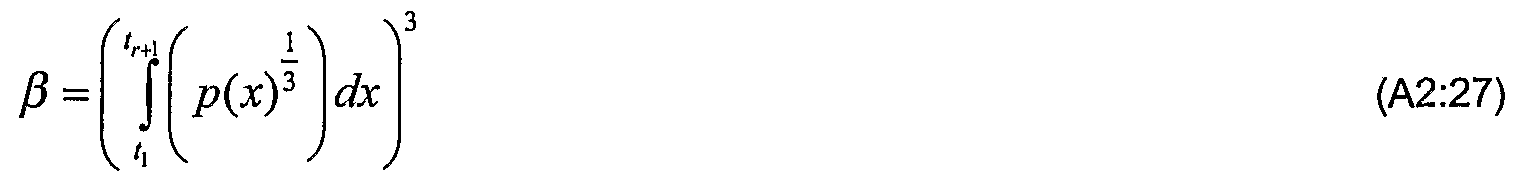
- the central coder distortion can be expressed by:
- the minimisation of the distortion expressed by expressions (A2:2), (A2:9), (A2:17) and (A2:22) should be performed over the set of all mapping functions (CC 0 , Ct x , (X 2 , ⁇ 0 ,..) relevant to the optimisation scenario.
Landscapes
- Engineering & Computer Science (AREA)
- Theoretical Computer Science (AREA)
- Physics & Mathematics (AREA)
- Probability & Statistics with Applications (AREA)
- Compression, Expansion, Code Conversion, And Decoders (AREA)
- Error Detection And Correction (AREA)
Abstract
Description


Claims

Priority Applications (4)
| Application Number | Priority Date | Filing Date | Title |
|---|---|---|---|
| JP2010527907A JP5159891B2 (en) | 2007-10-05 | 2008-03-28 | Method and apparatus for multiple description coding |
| US12/681,447 US20100215092A1 (en) | 2007-10-05 | 2008-03-28 | Method and Apparatus for Multiple Description Coding |
| CN2008801104513A CN101809873B (en) | 2007-10-05 | 2008-03-28 | Method and apparatus for multiple description coding |
| EP08724301A EP2193606A4 (en) | 2007-10-05 | 2008-03-28 | Method and apparatus for multiple description coding |
Applications Claiming Priority (2)
| Application Number | Priority Date | Filing Date | Title |
|---|---|---|---|
| US97779907P | 2007-10-05 | 2007-10-05 | |
| US60/977,799 | 2007-10-05 |
Publications (1)
| Publication Number | Publication Date |
|---|---|
| WO2009045148A1 true WO2009045148A1 (en) | 2009-04-09 |
Family
ID=40526449
Family Applications (1)
| Application Number | Title | Priority Date | Filing Date |
|---|---|---|---|
| PCT/SE2008/050355 Ceased WO2009045148A1 (en) | 2007-10-05 | 2008-03-28 | Method and apparatus for multiple description coding |
Country Status (6)
| Country | Link |
|---|---|
| US (1) | US20100215092A1 (en) |
| EP (1) | EP2193606A4 (en) |
| JP (1) | JP5159891B2 (en) |
| KR (1) | KR101589318B1 (en) |
| CN (1) | CN101809873B (en) |
| WO (1) | WO2009045148A1 (en) |
Families Citing this family (4)
| Publication number | Priority date | Publication date | Assignee | Title |
|---|---|---|---|---|
| US20110164672A1 (en) * | 2010-01-05 | 2011-07-07 | Hong Jiang | Orthogonal Multiple Description Coding |
| US9020029B2 (en) * | 2011-01-20 | 2015-04-28 | Alcatel Lucent | Arbitrary precision multiple description coding |
| US9203427B2 (en) * | 2011-02-10 | 2015-12-01 | Alcatel Lucent | System and method for mitigating the cliff effect for content delivery over a heterogeneous network |
| CN103503320B (en) | 2011-05-23 | 2016-10-05 | 华为技术有限公司 | For reconstructing method and the decoder of source signal |
Family Cites Families (6)
| Publication number | Priority date | Publication date | Assignee | Title |
|---|---|---|---|---|
| US6047395A (en) * | 1998-01-30 | 2000-04-04 | Cirrus Logic, Inc. | Error correction processor for correcting a multi-dimensional code by generating an erasure polynomial over one dimension for correcting multiple codewords in another dimension |
| EP0985697B1 (en) * | 1998-03-24 | 2006-01-04 | Nof Corporation | Oxirane derivatives and process for producing the same |
| US6983243B1 (en) * | 2000-10-27 | 2006-01-03 | Lucent Technologies Inc. | Methods and apparatus for wireless transmission using multiple description coding |
| JP4123856B2 (en) * | 2001-07-31 | 2008-07-23 | 日油株式会社 | Bio-related substance modifier and method for producing polyoxyalkylene derivative |
| EP1465349A1 (en) * | 2003-03-31 | 2004-10-06 | Interuniversitair Microelektronica Centrum Vzw | Embedded multiple description scalar quantizers for progressive image transmission |
| CN1633180A (en) * | 2004-12-24 | 2005-06-29 | 海信集团有限公司 | Multi-description video coding method based on transformation and data fusion |
-
2008
- 2008-03-28 US US12/681,447 patent/US20100215092A1/en not_active Abandoned
- 2008-03-28 JP JP2010527907A patent/JP5159891B2/en not_active Expired - Fee Related
- 2008-03-28 CN CN2008801104513A patent/CN101809873B/en not_active Expired - Fee Related
- 2008-03-28 WO PCT/SE2008/050355 patent/WO2009045148A1/en not_active Ceased
- 2008-03-28 KR KR1020107009887A patent/KR101589318B1/en not_active Expired - Fee Related
- 2008-03-28 EP EP08724301A patent/EP2193606A4/en not_active Withdrawn
Non-Patent Citations (4)
| Title |
|---|
| "Digital Signal Processing Workshop, 2002 and the 2nd Signal Processing Education Workshop. Proceedings of 2002 IEEE 10th", 13 October 2002, article VORAN S.D.: "The channel-optimized multiple-description scalar quantizer", pages: 400 - 405, XP010657835 * |
| "Image Processing, 2001. Proceedings. 2001 International Conference on", vol. 1, 2001, article GUIONNET T. ET AL: "Embedded multiple description coding for progressive image transmission over unreliable channels", pages: 94 - 97, XP010564804 * |
| BERGER-WOLF T.Y. ET AL: "Index assignment for multichannel communication under failure", INFORMATION THEORY, IEEE TRANSACTIONS ON, vol. 48, no. 10, October 2002 (2002-10-01), pages 2656 - 2668, XP011074590 * |
| SAGETONG P. ET AL: "Optimal bit allocation for channel-adaptive multiple description coding", PROCEEDINGS OF VCIP'2000, 2000, XP008007257, Retrieved from the Internet <URL:http://sipi.usc.edu/~ortega/./Papers/ei2000-sagetong.pdf> * |
Also Published As
| Publication number | Publication date |
|---|---|
| KR20100091958A (en) | 2010-08-19 |
| JP2010541466A (en) | 2010-12-24 |
| KR101589318B1 (en) | 2016-01-27 |
| JP5159891B2 (en) | 2013-03-13 |
| US20100215092A1 (en) | 2010-08-26 |
| CN101809873B (en) | 2013-11-06 |
| EP2193606A4 (en) | 2013-02-27 |
| EP2193606A1 (en) | 2010-06-09 |
| CN101809873A (en) | 2010-08-18 |
Similar Documents
| Publication | Publication Date | Title |
|---|---|---|
| US8325622B2 (en) | Adaptive, scalable packet loss recovery | |
| Batllo et al. | Asymptotic performance of multiple description transform codes | |
| JP7508633B2 (en) | Layered coding and data structures for compressed high-order Ambisonics sound or sound field representations - Patents.com | |
| EP2193606A1 (en) | Method and apparatus for multiple description coding | |
| Hagen et al. | Robust vector quantization by a linear mapping of a block code | |
| US9287895B2 (en) | Method and decoder for reconstructing a source signal | |
| CN113992303B (en) | Sequence determination method, device and equipment | |
| KR20150112802A (en) | Apparatus and method for channel information feedback in wireless communication system | |
| Jiang et al. | Joint rate and resource allocation in hybrid digital–analog transmission over fading channels | |
| JP6765355B2 (en) | How to decode decoders, encoders and coded values | |
| Farvardin et al. | Performance of entropy-constrained block transform quantizers | |
| Abou Saleh et al. | Power-constrained bandwidth-reduction source-channel mappings for fading channels | |
| Klejsa et al. | Adaptive resolution-constrained scalar multiple-description coding | |
| Méhes et al. | Performance of quantizers on noisy channels using structured families of codes | |
| KR101116170B1 (en) | Vector quantization method of data signal and record media recorded for realizing the same | |
| Åstrand et al. | Efficient Multiple Description Coding Using Sparse Linear Regression | |
| Chan et al. | Multiple description and matching pursuit coding for video transmission over the internet | |
| Movassagh et al. | Joint entropy-scalable coding of audio signals | |
| Dumitrescu et al. | Asymptotical analysis of several multiple description scenarios with L≥ 3 descriptions | |
| CN120476558A (en) | Apparatus and method for efficient communication in a cellular communication network | |
| Abou Saleh | Source-Channel Mappings with Applications to Compressed Sensing | |
| Farthofer | Performance limits of Gaussian channels with quantized feedback | |
| Xu et al. | Distortion optimized multiple channel image transmission under delay constraints | |
| Liang et al. | Beating the bounds on stabilizing data rates in networked systems | |
| Johansson | On the source-channel coding tradeoff in networked control |
Legal Events
| Date | Code | Title | Description |
|---|---|---|---|
| WWE | Wipo information: entry into national phase |
Ref document number: 200880110451.3 Country of ref document: CN |
|
| 121 | Ep: the epo has been informed by wipo that ep was designated in this application |
Ref document number: 08724301 Country of ref document: EP Kind code of ref document: A1 |
|
| DPE1 | Request for preliminary examination filed after expiration of 19th month from priority date (pct application filed from 20040101) | ||
| DPE1 | Request for preliminary examination filed after expiration of 19th month from priority date (pct application filed from 20040101) | ||
| WWE | Wipo information: entry into national phase |
Ref document number: 2010527907 Country of ref document: JP |
|
| REEP | Request for entry into the european phase |
Ref document number: 2008724301 Country of ref document: EP |
|
| WWE | Wipo information: entry into national phase |
Ref document number: 2008724301 Country of ref document: EP |
|
| WWE | Wipo information: entry into national phase |
Ref document number: 12681447 Country of ref document: US |
|
| NENP | Non-entry into the national phase |
Ref country code: DE |
|
| ENP | Entry into the national phase |
Ref document number: 20107009887 Country of ref document: KR Kind code of ref document: A |