WO2009034303A1 - Improvements in liquid dispensing devices - Google Patents
Improvements in liquid dispensing devices Download PDFInfo
- Publication number
- WO2009034303A1 WO2009034303A1 PCT/GB2008/003034 GB2008003034W WO2009034303A1 WO 2009034303 A1 WO2009034303 A1 WO 2009034303A1 GB 2008003034 W GB2008003034 W GB 2008003034W WO 2009034303 A1 WO2009034303 A1 WO 2009034303A1
- Authority
- WO
- WIPO (PCT)
- Prior art keywords
- arc
- flow directing
- central axis
- nozzle
- fluid passage
- Prior art date
- Legal status (The legal status is an assumption and is not a legal conclusion. Google has not performed a legal analysis and makes no representation as to the accuracy of the status listed.)
- Ceased
Links
Classifications
-
- B—PERFORMING OPERATIONS; TRANSPORTING
- B65—CONVEYING; PACKING; STORING; HANDLING THIN OR FILAMENTARY MATERIAL
- B65D—CONTAINERS FOR STORAGE OR TRANSPORT OF ARTICLES OR MATERIALS, e.g. BAGS, BARRELS, BOTTLES, BOXES, CANS, CARTONS, CRATES, DRUMS, JARS, TANKS, HOPPERS, FORWARDING CONTAINERS; ACCESSORIES, CLOSURES, OR FITTINGS THEREFOR; PACKAGING ELEMENTS; PACKAGES
- B65D47/00—Closures with filling and discharging, or with discharging, devices
- B65D47/04—Closures with discharging devices other than pumps
- B65D47/06—Closures with discharging devices other than pumps with pouring spouts or tubes; with discharge nozzles or passages
- B65D47/12—Closures with discharging devices other than pumps with pouring spouts or tubes; with discharge nozzles or passages having removable closures
- B65D47/122—Threaded caps
- B65D47/123—Threaded caps with internal parts
-
- B—PERFORMING OPERATIONS; TRANSPORTING
- B65—CONVEYING; PACKING; STORING; HANDLING THIN OR FILAMENTARY MATERIAL
- B65D—CONTAINERS FOR STORAGE OR TRANSPORT OF ARTICLES OR MATERIALS, e.g. BAGS, BARRELS, BOTTLES, BOXES, CANS, CARTONS, CRATES, DRUMS, JARS, TANKS, HOPPERS, FORWARDING CONTAINERS; ACCESSORIES, CLOSURES, OR FITTINGS THEREFOR; PACKAGING ELEMENTS; PACKAGES
- B65D1/00—Rigid or semi-rigid containers having bodies formed in one piece, e.g. by casting metallic material, by moulding plastics, by blowing vitreous material, by throwing ceramic material, by moulding pulped fibrous material or by deep-drawing operations performed on sheet material
- B65D1/02—Bottles or similar containers with necks or like restricted apertures, designed for pouring contents
- B65D1/0223—Bottles or similar containers with necks or like restricted apertures, designed for pouring contents characterised by shape
- B65D1/023—Neck construction
Definitions
- the present invention relates to the improvements in liquid dispensing devices. More specifically, the present invention relates to improved nozzles used to dispense liquid compositions from a container or a flask containing a quantity of the liquid composition which is intended to be directed in a controlled fashion therefrom, particularly in the form of a controllable liquid stream.
- flow directing nozzles are advantageously included that they provide a means by which a user dispensing a quantity of such a liquid treatment composition from a bottle can exert some degree of control over the direction of the stream of the liquid composition exiting to the bottle via the nozzle.
- surfaces of such lavatory appliances are often obscured from view, or are inclined surfaces or may be surfaces which are positioned such that ideally the dispensing device would need to direct a stream or a jet of the liquid treatment composition in a direction which was directed above the horizontal such that the stream or jet was at least partially vertical.
- a flow directing nozzle which is adapted to be used to dispense a liquid composition, such as a treatment composition primarily directed to be used for the cleaning and/or disinfecting and/or sanitizing treatment of a lavatory appliance particularly a toilet bowl.
- a dispensing container having mounted thereon a flow directing nozzle which is adapted to be used to dispense a liquid composition, such as a treatment composition primarily directed to be used for the cleaning and/or disinfecting and/or sanitizing treatment of a lavatory appliance particularly a toilet bowl.
- sealable dispensing container according to the second aspect of the invention wherein said dispensing container includes said flow directing nozzle as well as further includes a closure.
- an improved method for dispensing a quantity of a liquid treatment composition from a container such as a dispensing container provided with an improved flow directing nozzle which is adapted to provide improved control over the directional dispensing of a stream of said liquid composition, such as a liquid treatment composition primarily directed to be used for the cleaning and/or disinfecting and/or sanitizing treatment of a lavatory appliance particularly a toilet bowl.
- the present invention provides a flow directing nozzle which is adapted to be used to dispense a liquid composition, such as a liquid treatment composition primarily directed to be used for the cleaning and/or disinfecting and/or sanitizing treatment of a lavatory appliances and especially a toilet bowl.
- a liquid composition such as a liquid treatment composition primarily directed to be used for the cleaning and/or disinfecting and/or sanitizing treatment of a lavatory appliances and especially a toilet bowl.
- the flow directing nozzle provides for improved directional dispensing of a stream of said liquid composition from a dispensing container upon which the flow directing nozzle is mounted.
- Such improved directional dispensing provides for the directed application of the liquid treatment composition onto surfaces of lavatory appliances which may be obscured from view, and/or onto inclined surfaces and/or surfaces which are positioned wherein the stream or a jet of the liquid treatment composition needs be oriented in a direction which above the horizontal such that the stream or jet is at least partially vertical.
- Such improved directional dispensing provides for the dispensing of a stream or a jet of the liquid treatment composition to the underside of the interior of the rim of the toilet bowl, a locus which is known in the art to be a particularly difficult area of the toilet bowl to clean, but at which the formation of hard water stains, rust stains, or other stains typically are known to occur.
- the geometry of the nozzle provides for an angular deflection of the stream or jet of the liquid treatment composition exiting said the nozzle.
- This allows for the improved placement of the dispensing device, viz., a bottle, containing the liquid treatment composition with respect to the lavatory appliance, and particularly with respect to portions of a toilet bowl.
- the placement and relative angular positioning of the dispensing device, viz., bottle frequently required partial or near total insertion of the dispensing device within the interior of the toilet bowl in order to ensure proper directional dispensing of the stream or jet of the liquid treatment composition exiting its nozzle
- the improved flow directing nozzle according to the present invention does not require the same.
- the improved flow directing nozzle is one which can be easily adapted for use with a variety of dispensing devices, especially bottles having essentially bottle necks which are generally circular bores extending from the exterior of the bottle and into the interior cavity of the bottle within which the liquid treatment composition would be provided and stored between dispensing.
- the improved flow directing nozzles according to the invention can be readily adapted for use with known-art existing bottle designs which would not need to be reconfigured in order to enjoy the benefits provided by the flow directing nozzles being toward herein.
- the improved flow directing nozzles include fluid passage which is generally in the form of hollow cylindrical shaft having a proximal end, and a distal end to which the liquid treatment composition is dispensed from said that nozzle.
- the cylindrical shaft is on a uniform diameter or cross-sectional area between the proximal end and a distal end however, this is not a critical requirement and some degree of tapering can be permitted between these two actions. For example, coming into consideration would be an angular taper of between 0.5° of arc and 20° of arc measured between the proximal and distal ends of the fluid passage. Providing such taper might be useful in circumstances wherein it is desired to increase the exit velocity of a stream or jet of the liquid treatment composition exiting the nozzle.
- the distal end of the fluid passage it is at least partially domed, and includes a fluid outlet which is angled with respect to a central axis of the fluid passage.
- the fluid passage is a fluid outlet which is an opening which is preferably defined by a plane crossing the central axis at an angle of between 5°of arc and 85° of arc, preferably between about 20° of arc and about 75° of arc, yet more preferably between about 30° of arc and about 60° of arc, and most preferably between about 32° of arc and 55° of arc with respect to the central axis and, preferably also the plane partially intersects the domed portion of the distal end of the fluid passage.
- the opening is preferably defined by a plane crossing the central axis at an angle of between 42°of arc and 48° of arc, and particularly preferably at 45° of arc.
- the radius of the domed end is circular with respect to a point on the central axis, however, the domed end may in certain circumstances be defined as noncircular, or elliptical with respect to a point on the central axis. Preferably however, the radius of the domed end is however circular with respect to a point on the central axis.
- the fluid outlet is planar in a cross-sectional view with respect to the central axis as noted above but this is not a limitation and the geometry of the fluid outlet may be a configuration having a geometry other than planar, such as might be defined by one or more cylindrical, conical or hyperbolic sections intersecting the central axis, and is also preferably angled with respect to the central axis at an angle of between 5°of arc and 85° of arc, preferably between about 20° of arc and about 75° of arc, yet more preferably v between about 30° of arc and about 60° of arc, and most preferably between about 32° of arc and 55° of arc with respect to the central axis and, preferably such other one or more cylindrical, conical or hyperbolic sections partially intersects the domed portion of the distal end of the fluid passage and thereby define the fluid outlet.
- a geometry other than planar such as might be defined by one or more cylindrical, conical or hyperbolic sections intersecting the central axis, and is also
- the fluid outlet is preferably planar in a cross-sectional view with respect to the central axis of the fluid passage especially where such passage is generally in the form of hollow cylindrical shaft, from a top plan view the fluid outlet is advantageously circular having a center point which is coincident with the central axis of the of the fluid passage.
- the improved flow directing nozzles of the invention typically include a skirt a portion of which may extend radially outwardly from the fluid passage in the form of a generally planar base portion from which extends in a distal direction a skirt sidewall having a geometry which is dimensioned such that the flow directing nozzles can be inserted into a portion of a container such as a bottle.
- the dimensions of the skirt and in particular the dimensions of the skirt sidewall are such that they are adapted to be inserted into the interior of the neck of a container, such as a bottle.
- the overall geometric dimensions the skirt are generally cylindrical wherein the skirt sidewall it is a generally cylindrical section which has a central axis which is coincident with the central axis of the fluid passage.
- a margin member which may include a flat surface or a lip having an lower flat surface which engages on the one side with the end of a bottle neck so to optionally provide a generally liquid-tight seal therewith and also limits the insertion of the nozzle into the bottle neck, with while on the other side there is a top face which may come in to sealing -type contact with a portion of a closure which may be used with the dispensing device.
- the exterior dimensions of the skirt are such that any can form an interference tight fit, preferably a liquid-tight interference type fit with the interior dimensions of a bottle neck.
- the nozzle may include one or further ancillary elements relative to the skirt sidewall but preferably forming part of the skirt sidewall which may be used to provide an improved interference tight fit, preferably a liquid -tight interference type fit with the interior dimensions of a bottle neck when the nozzle is mounted on a container, viz., a bottle.
- the dispensing device according to the invention further includes a closure.
- the closure may take the form of a conventional cap and have an internal cavity which is dimensioned in order to and encompass a least a part of the nozzle and at least a part of the bottle neck upon which the nozzle is mounted.
- a plug element from a top inner surface on the closure, various extending downwardly and concentrically with the center line of the closure a plug elements.
- the plug element is generally circular cross-section, or it may be slightly tapered or in some embodiments the plug element of the closure may be conical in shape.
- the plug element is dimensioned such that when the closure is mounted upon the dispensing device and simultaneously onto the nozzle the plug element extends through the fluid outlet and into the interior of the fluid passage of the nozzle.
- the plug element is dimensioned such that provide at least an interference type fit and preferably also provides a liquid type seal between portions of the plot, such as side walls of the plug, and the margins of the fluid outlet.
- a generally reliable liquid-tight seal can be formed by the interface between these two elements.
- the plug has a geometry which is symmetrical about the central axis of the closure, and also in a plan of view, the margins of the fluid outlet are also symmetrical about the central axis of the fluid passage, the overall dimensions of the closure and on the improved fluid nozzle can be dimensioned such that the central axis of the closure and the central axis of the fluid nozzle are coincident when the closure is mounted upon the dispensing device and in particular when mounted upon the nozzle.
- a further important technical feature of the improved flow directing nozzles of the invention is that as the planar face of the fluid outlets are not perpendicular to the central axis of the fluid passage, but rather are angled with respect thereto, such geometry of the nozzle and its fluid outlet provides for the angular deflection of the stream or jet of the liquid treatment composition exiting said the nozzle with respect to the central axis of the fluid passage of the nozzle.
- This allows for the improved placement of the dispensing device, viz., a bottle, containing the liquid treatment composition with respect to the lavatory appliance, and particularly with respect to portions of a toilet bowl.
- prior art dispensers typically requires the positioning of the dispensing device, viz., bottle, usually at least partially and too often usually requires near total insertion of the bottle within the interior of the toilet bowl in order to ensure proper directional dispensing of the stream or jet of the liquid treatment composition exiting its nozzle to the underside of a toilet bowl rim, such is not required of dispensing devices which include the improved flow directing nozzles taught herein.
- FIG. 1 illustrates in a side cross-sectional view a flow directing nozzle 10 which is adapted to be used to dispense a liquid composition from a container such as if by which the nozzle 10 is mounted.
- the nozzle 10 includes a shaft 12 having a proximal end 14 and a distal end 16.
- a skirt 20 which includes a skirt base 22 which is generally perpendicular to the sidewall 18 of the shaft 12 which skirt base 22 extends to a chamber section 24, which is angled distally with respect to the skirt base 22, from whence they skirt continues to a skirt sidewall 26 which is generally circular, and concentric about a central axis "C".
- skirt lip 28 which here, is in the form of a generally flat member which is integrally formed as part of the skirt 20 and includes a top face 28a and a bottom face 28b which bottom face it also a generally flat member which is parallel to the top face 28a.
- a hollow shaft which is generally circular in cross section and has a uniform cross-sectional area across most of its distance between its proximal end 14 and distal end 16 however it is to be understood that the central axis "D" of the hollow interior of the shaft 12 is not coincident with the central axis "C", but rather is offset thereto.
- a domed section 30 which extends from and is integrally formed with the shaft 12.
- an inner semi- hemispherical sidewall 34 which extends towards the fluid outlet 36.
- the fluid outlet 36 is in this embodiment, seen to be an opening spanning a part of the shaft 12 at a plane angled with respect to the central axis. Such an angled opening of the fluid outlet 26 also contributes to redirecting the direction of fluid flow from being one generally coincident with the axes C and D, to a direction of flow which is now angled by an angle "K" with respect thereto. While the angle K shown in Fig 1.
- the angle K may vary from between about 5°of arc and about 85° of arc, preferably between about 20° of arc and about 75° of arc, yet more preferably between about 30° of arc and about 60° of arc, and most preferably between about 32° of arc and 55° of arc with respect to the central axis.
- An angle of between about 40° of arc and 50° of arc is especially preferred.
- Figure 3 illustrates in a perspective view, the nozzle 10 inserted into a neck portion 52 of bottle 50. As is visible from the figure, the nozzle 10 is inserted partially within the neck 52 with the lip 28 of the nozzle 10 abutting the top margin 52a of the neck. Further visible on the exterior portion of the neck 52 are a series of threads 54 which are adapted to interact or make with corresponding threads of a closure which are however not shown in the figure.
- Figure 4 depicts in a cross-sectional view a preferred embodiments of any nozzle 10 according to the invention, which is generally in accordance with the embodiment disclosed and discussed with reference to Fig. 1 , a portion of a bottle 50 illustrating the closure 10 inserted within the neck 52 thereof and a removable closure 70 mounted upon both a part of the closure 10 and the bottle neck 52.
- the closure 70 includes an internal cavity 72, within which is a plug 74 which extends downwardly from a top part 76 of the closure.
- the plus 74 has the form of a downwardly directed, slightly tapering column having a sidewall 78 which forms an interference tight fit, preferably a liquid tight fit between the sidewall 70 and the margins 36a on the fluid opening 36.
- the plug 74 is preferably and desirably concentric about a central axis C, and simultaneously, when the closure 70 is mounted any is the nozzle 10 the plot 74 is engaged within the fluid outlet 36 which can be plan view as discussed with reference to Fig. 2 is also concentric about this central axis C.
- Such an inter-relational geometry provides an important advantage of the nozzles of the invention in that while the dimensions and the central axis of the shaft 12 can be offset with regard to the central axis C, the orientation of the fluid outlet 36 its preferred geometry in both being circular and coincident with central axis C when projected onto a plane perpendicular to central axis C, but intersecting the shaft 12 in a plane which is angled with respect to central axis C provides on the one hand this the ability to alter the direction of the fluid flow passing through the shaft 12, it on the other hand preserves concentricity with respect to the closure 70 and preferably also preserves concentricity with the neck 52 of the bottle 50 within which the nozzle 10 is mounted.
- a consumer may still easily, and reliably attach and remove the closure 70 from the bottle 50 in the usual manner, as the plug 74 and the fluid outlet 36 come into alignment and form an interference tight fit, but preferably a liquid tight fit therebetween.
- additional contact between the closure 70 and the nozzle may occur by contact between the top faced 28 any an inner portion 77 of the skirt 78 which extends downwardly from the top 76 of the closure 70.
- corresponding mating threads 79 may be provided on an inner surface 79 of the skirt 78 which corresponding mating threads 79 engaging mating threads 54 present on part of the neck 52 of the bottle 50.
- Figure A depicts for illustrative purposes, a conventional prior art and nozzle 100 mounted within a part of a neck 52 of a bottle 50.
- nozzle 100 includes a hollow central shaft 102 which terminates at an opening 104; as is visible, both the hollow central shaft 102 and the fluid outlet 104 are concentric to the central axis C. Additionally, the fluid outlet 104 may be defined by a perpendicular plane intersecting the central axis C, but that the perpendicular plane and hence the angle of the fluid outlet is only perpendicular to the central axis C.
- Fig. 5 depicts a dispensing device 90 according to the invention which includes a bottle 50 having 80 nozzle and mounted within a portion of the neck 52 thereof.
- the bottle while having a generally linear axis, and coincident with the axis M running centrally along its back wall, has a curved neck region 54 which deflects the central axis C of the neck 52 by an angle N away from the bottle's back wall 53.
- the nozzle 10 is mounted with respect to the neck 52 such that the fluid opening 36 is also directed away from the back wall 53.
- direction of fluid exiting the fluid opening 36 and is generally in direction of the line F, which is angled by an amount "K" with respect to the central axis C.
- both specific geometries of a bottle 50 as well and specific placement on the improved nozzle 10 with respect to the neck of the bottle can be used to impart a specific directional displacement of the direction of the direction of fluid exiting the fluid opening 36 and is generally in direction of the line F with respect to the back wall 53 of the bottle 50.
- Figures 6 and B respectively illustrate a dispensing device according to the invention, and a dispensing a device according to the prior art.
- Fig. 6 depicts in a cross-sectional representational view if dispensing device 90 including an improved nozzle 10 according to the invention mounted in a bottle 50.
- the nozzle 10 is positioned such that the direction of the fluid stream F of the liquid treatment composition exiting the bottle 50 is directed towards the underside 202 of the top rim 204 of a toilet bowl 200.
- most of the bottle 50 may be positioned above the margin of the rim 204 and effective delivery of the liquid treatment composition to the underside of the rim thereto does not require substantial placement of the bottle 50 within the interior 206 of the toilet bowl 200.
- This is also evidenced by the angle "Z" defined which defined by the angle is formed between the back wall 53 of the bottle 50 and a horizontal line “H” the latter being coincident with the top rim 204 of the toilet bowl 200.
- Fig. B illustrates the relative placement of a prior art bottle 50 bearing a prior art and nozzle.
- a substantial portion of the bottle 50 must be placed within the interior 206 of the toilet bowl 200 in order to provide ample directional flow towards the underside 202 of the top rim 204 of the toilet bowl 200.
- the angle "Z" defined which defined by the angle is formed between the back wall 53 of the bottle 50 and a horizontal line “H" the latter being coincident with the top rim 204 of the toilet bowl 200 is much smaller than that of the embodiment of the invention discussed with reference to Fig. 6.
- the bottle and nozzle according to the prior art and depicted on Fig. B required a much of the bottle and nozzle according to the prior art and depicted on Fig. B required a much
- the angle "Z" was greater for the dispensing device according to the invention, viz., bottle and nozzle according to Figures 1, 2, 3 and 5 than using the prior art nozzle with the bottle of Fig. 5. This permitted the user to incline the bottle less in order to initiate dispensing of the treatment composition from the bottle via the nozzle, than the use of the prior art nozzle and bottle, as is depicted with reference to Fig. 6 and Fig. B.
- the present invention provides an improved method for dispensing a quantity of a liquid treatment composition from a container, such as a dispensing container provided with an improved flow directing nozzle which is adapted to provide improved control over the directional dispensing of a stream of said liquid composition, such as a liquid treatment composition primarily directed to be used for the cleaning and/or disinfecting and/or sanitizing treatment of a lavatory appliance particularly a toilet bowl.
- the nozzles of the invention, as well as the dispensing devices may be formed of any suitable material.
- Advantageously naturally occurring or synthetic polymers provide excellent materials of construction as they are readily molded or otherwise formed into appropriate shapes and configurations. Additionally such polymers are often resistant to the treatment compositions, and particularly with respect to the bottle are resilient and flexible, and thus provide for compressible flasks or bottles.
- Such are known to the art and include, e.g., any of a number of thermosettable or thermoformable synthetic polymers such as are widely used in casting or injection molding.
- Exemplary synthetic polymers such as polyamides, polyolefins (e.g., polypropylene, polyethylene) as well as polyalkyleneterephalates (i.e., polyethylene terephthalate, polybutylene terephthalate), polystyrenes, polysulfones, polycarbonates as well as copolymers formed from monomers of one or more of the foregoing being several nonlimiting examples of useful synthetic polymers.
- Other materials which may be used include metals, glass, elastomeric polymers both naturally occurring and synthetic, as well as any other material which can be suitably shaped or formed into the nozzles of the invention , as well as the dispensing devices.
- the dispensing devices of the invention provide a particularly effective device for the effective storage and spray or stream delivery of liquid treatment compositions onto a surface needing treatment by the composition, particularly wherein the dispensing device is for the directed delivery of a liquid treatment composition to a portion of a toilet bowl, and particularly to the underside of the rim of a toilet bowl.
Landscapes
- Engineering & Computer Science (AREA)
- Mechanical Engineering (AREA)
- Ceramic Engineering (AREA)
- Nozzles (AREA)
Abstract
A flow directing nozzle which is adapted to be used to dispense a liquid composition, such as a treatment composition primarily directed to be used for the cleaning and/or disinfecting and/or sanitizing treatment of a lavatory appliance particularly a toilet bowl.
Description
IMPROVEMENTS IN LIQUID DISPENSING DEVICES
The present invention relates to the improvements in liquid dispensing devices. More specifically, the present invention relates to improved nozzles used to dispense liquid compositions from a container or a flask containing a quantity of the liquid composition which is intended to be directed in a controlled fashion therefrom, particularly in the form of a controllable liquid stream.
The prior art is replete with various dispensing containers which are useful in both scoring and dispensing liquid therefrom. Certain of these include flow directing nozzles which are typically inserted in the neck of a flask, or more particularly typically in the neck of a bottle which contains a quantity of a liquid treatment composition. These flow directing nozzles can be a closure for the bottle or may be used in conjunction with a further closure in order to provide a removable sealing means in order to ensure that the contents of the bottle are not prematurely dispensed. Such nozzles and closures are known from a variety of consumer products including a variety of cleaning products. For example, cleaning products which are particularly adapted to be used in the cleaning of lavatory appliances, such as a toilet bowl, are frequently provided with flow directing nozzles. Such flow directing nozzles are advantageously included that they provide a means by which a user dispensing a quantity of such a liquid treatment composition from a bottle can exert some degree of control over the direction of the stream of the liquid composition exiting to the bottle via the nozzle. Such as beneficial as, in many instances, surfaces of such lavatory appliances are often obscured from view, or are inclined surfaces or may be surfaces which are positioned such that ideally the dispensing device would need to direct a stream or a jet of the liquid treatment composition in a direction which was directed above the horizontal such that the stream or jet was at least partially
vertical. For example, such would be required if it were desired to direct a stream or a jet of a liquid treatment composition to the underside of the interior of the rim of the toilet bowl. This locus is known in the art to be a particularly difficult area of the toilet bowl to clean, and yet is also known to the art as being the locus at which the formation of hard water stains, rust stains, or other stains typically formed as a consequence of the quality of the water used to supply the toilet bowl are known to occur. Thus, access to this locus provides a technical challenge which has not been wholly satisfactorily addressed by flow directing nozzles or by dispensing containers which include such flow directing nozzles. If it is to such a technical shortcoming, as well as further technical shortcomings that the present invention is primarily directed.
Accordingly, in one aspect of present invention provides a flow directing nozzle which is adapted to be used to dispense a liquid composition, such as a treatment composition primarily directed to be used for the cleaning and/or disinfecting and/or sanitizing treatment of a lavatory appliance particularly a toilet bowl. hi a second aspect of the present invention there is provided a dispensing container having mounted thereon a flow directing nozzle which is adapted to be used to dispense a liquid composition, such as a treatment composition primarily directed to be used for the cleaning and/or disinfecting and/or sanitizing treatment of a lavatory appliance particularly a toilet bowl. hi a third aspect of the invention there is provided sealable dispensing container according to the second aspect of the invention wherein said dispensing container includes said flow directing nozzle as well as further includes a closure.
According to a fourth aspect of the invention there is provided an improved method for dispensing a quantity of a liquid treatment composition from a container, such as a dispensing container provided with an improved flow directing nozzle which is adapted to provide improved control over the directional dispensing of a stream of said liquid composition, such as a liquid treatment composition primarily directed to be used for the cleaning and/or disinfecting and/or sanitizing treatment of a lavatory appliance particularly a toilet bowl. These and further aspects of the invention will be in further detail with reference to one or more of the embodiments disclosed herein.
Broadly speaking the present invention provides a flow directing nozzle which is adapted to be used to dispense a liquid composition, such as a liquid treatment composition primarily directed to be used for the cleaning and/or disinfecting and/or sanitizing treatment of a lavatory appliances and especially a toilet bowl. The flow directing nozzle provides for improved directional dispensing of a stream of said liquid composition from a dispensing container upon which the flow directing nozzle is mounted. Such improved directional dispensing provides for the directed application of the liquid treatment composition onto surfaces of lavatory appliances which may be obscured from view, and/or onto inclined surfaces and/or surfaces which are positioned wherein the stream or a jet of the liquid treatment composition needs be oriented in a direction which above the horizontal such that the stream or jet is at least partially vertical. Such improved directional dispensing provides for the dispensing of a stream or a jet of the liquid treatment composition to the underside of the interior of the rim of the toilet bowl, a locus which is known in the art to be a particularly difficult area of the toilet bowl to clean, but at which the formation of hard water stains, rust stains, or other stains typically are known to occur.
An important technical advantage provided by the flow directing nozzle is that the geometry of the nozzle provides for an angular deflection of the stream or jet of the liquid treatment composition exiting said the nozzle. This allows for the improved placement of the dispensing device, viz., a bottle, containing the liquid treatment composition with respect to the lavatory appliance, and particularly with respect to portions of a toilet bowl. Whereas in prior art compositions the placement and relative angular positioning of the dispensing device, viz., bottle, frequently required partial or near total insertion of the dispensing device within the interior of the toilet bowl in order to ensure proper directional dispensing of the stream or jet of the liquid treatment composition exiting its nozzle, the improved flow directing nozzle according to the present invention does not require the same. Further, the improved flow directing nozzle is one which can be easily adapted for use with a variety of dispensing devices, especially bottles having essentially bottle necks which are generally circular bores extending from the exterior of the bottle and into the interior cavity of the bottle within which the liquid treatment composition would be provided and stored between dispensing. Thus, the improved flow directing
nozzles according to the invention can be readily adapted for use with known-art existing bottle designs which would not need to be reconfigured in order to enjoy the benefits provided by the flow directing nozzles being toward herein.
The improved flow directing nozzles include fluid passage which is generally in the form of hollow cylindrical shaft having a proximal end, and a distal end to which the liquid treatment composition is dispensed from said that nozzle. In preferred embodiments, the cylindrical shaft is on a uniform diameter or cross-sectional area between the proximal end and a distal end however, this is not a critical requirement and some degree of tapering can be permitted between these two actions. For example, coming into consideration would be an angular taper of between 0.5° of arc and 20° of arc measured between the proximal and distal ends of the fluid passage. Providing such taper might be useful in circumstances wherein it is desired to increase the exit velocity of a stream or jet of the liquid treatment composition exiting the nozzle. For example, should such be desired and then the introduction of an angular taper wherein the diameter or cross-sectional area of the distal end is less than the diameter or cross-sectional area of the proximal end is contemplated as being useful in providing such a technical result. The distal end of the fluid passage it is at least partially domed, and includes a fluid outlet which is angled with respect to a central axis of the fluid passage. From a side cross- sectional view the fluid passage is a fluid outlet which is an opening which is preferably defined by a plane crossing the central axis at an angle of between 5°of arc and 85° of arc, preferably between about 20° of arc and about 75° of arc, yet more preferably between about 30° of arc and about 60° of arc, and most preferably between about 32° of arc and 55° of arc with respect to the central axis and, preferably also the plane partially intersects the domed portion of the distal end of the fluid passage. In a certain particularly preferred embodiment the opening is preferably defined by a plane crossing the central axis at an angle of between 42°of arc and 48° of arc, and particularly preferably at 45° of arc. In preferred embodiments, the radius of the domed end is circular with respect to a point on the central axis, however, the domed end may in certain circumstances be defined as noncircular, or elliptical with respect to a point on the central axis. Preferably however, the radius of the domed end is however circular with respect to a point on the central axis.
Preferably the fluid outlet is planar in a cross-sectional view with respect to the central axis as noted above but this is not a limitation and the geometry of the fluid outlet may be a configuration having a geometry other than planar, such as might be defined by one or more cylindrical, conical or hyperbolic sections intersecting the central axis, and is also preferably angled with respect to the central axis at an angle of between 5°of arc and 85° of arc, preferably between about 20° of arc and about 75° of arc, yet more preferably v between about 30° of arc and about 60° of arc, and most preferably between about 32° of arc and 55° of arc with respect to the central axis and, preferably such other one or more cylindrical, conical or hyperbolic sections partially intersects the domed portion of the distal end of the fluid passage and thereby define the fluid outlet.
While the fluid outlet is preferably planar in a cross-sectional view with respect to the central axis of the fluid passage especially where such passage is generally in the form of hollow cylindrical shaft, from a top plan view the fluid outlet is advantageously circular having a center point which is coincident with the central axis of the of the fluid passage.
Extending outward from the proximal end of the fluid passage the improved flow directing nozzles of the invention typically include a skirt a portion of which may extend radially outwardly from the fluid passage in the form of a generally planar base portion from which extends in a distal direction a skirt sidewall having a geometry which is dimensioned such that the flow directing nozzles can be inserted into a portion of a container such as a bottle.. Most preferably, the dimensions of the skirt and in particular the dimensions of the skirt sidewall are such that they are adapted to be inserted into the interior of the neck of a container, such as a bottle. Most preferably, the overall geometric dimensions the skirt are generally cylindrical wherein the skirt sidewall it is a generally cylindrical section which has a central axis which is coincident with the central axis of the fluid passage. Optionally, but desirably in many embodiments at the top margin of the skirt sidewall there is provided a margin member which may include a flat surface or a lip having an lower flat surface which engages on the one side with the end of a bottle neck so to optionally provide a generally liquid-tight seal therewith and also limits the insertion of the nozzle into the bottle neck, with while on the other side there is a top face which may come in to sealing -type contact with a portion of a closure which
may be used with the dispensing device. Advantageously, the exterior dimensions of the skirt are such that any can form an interference tight fit, preferably a liquid-tight interference type fit with the interior dimensions of a bottle neck. If required, the nozzle may include one or further ancillary elements relative to the skirt sidewall but preferably forming part of the skirt sidewall which may be used to provide an improved interference tight fit, preferably a liquid -tight interference type fit with the interior dimensions of a bottle neck when the nozzle is mounted on a container, viz., a bottle.
In certain advantageous embodiments, the dispensing device according to the invention further includes a closure. The closure may take the form of a conventional cap and have an internal cavity which is dimensioned in order to and encompass a least a part of the nozzle and at least a part of the bottle neck upon which the nozzle is mounted. Advantageously, from a top inner surface on the closure, various extending downwardly and concentrically with the center line of the closure a plug elements. The plug element is generally circular cross-section, or it may be slightly tapered or in some embodiments the plug element of the closure may be conical in shape. Ideally, the plug element is dimensioned such that when the closure is mounted upon the dispensing device and simultaneously onto the nozzle the plug element extends through the fluid outlet and into the interior of the fluid passage of the nozzle. In particularly preferred embodiments the plug element is dimensioned such that provide at least an interference type fit and preferably also provides a liquid type seal between portions of the plot, such as side walls of the plug, and the margins of the fluid outlet. As such, according to particular preferred embodiments, a generally reliable liquid-tight seal can be formed by the interface between these two elements. Additionally, due to the fact that according to preferred embodiments the plug has a geometry which is symmetrical about the central axis of the closure, and also in a plan of view, the margins of the fluid outlet are also symmetrical about the central axis of the fluid passage, the overall dimensions of the closure and on the improved fluid nozzle can be dimensioned such that the central axis of the closure and the central axis of the fluid nozzle are coincident when the closure is mounted upon the dispensing device and in particular when mounted upon the nozzle. A further important technical feature of the improved flow directing nozzles of the invention is that as the planar face of the fluid outlets are not perpendicular to the
central axis of the fluid passage, but rather are angled with respect thereto, such geometry of the nozzle and its fluid outlet provides for the angular deflection of the stream or jet of the liquid treatment composition exiting said the nozzle with respect to the central axis of the fluid passage of the nozzle. This allows for the improved placement of the dispensing device, viz., a bottle, containing the liquid treatment composition with respect to the lavatory appliance, and particularly with respect to portions of a toilet bowl. For example the use of prior art dispensers typically requires the positioning of the dispensing device, viz., bottle, usually at least partially and too often usually requires near total insertion of the bottle within the interior of the toilet bowl in order to ensure proper directional dispensing of the stream or jet of the liquid treatment composition exiting its nozzle to the underside of a toilet bowl rim, such is not required of dispensing devices which include the improved flow directing nozzles taught herein. Additionally the use of prior art dispensers with many conventional prior art nozzles makes the total evacuation of the liquid treatment composition from the interior of such dispensing devices while directing the stream or jet of the liquid treatment composition exiting its nozzle to the underside of a toilet bowl rim nearly impossible as the liquid treatment composition fails to reach the nozzle in such a position rather only a blast of air from within the bottle is achieved. Thus, wastage of any liquid treatment composition often occurs in such a circumstance. Such technical shortcomings or however overcome by the use of dispensing devices provided with the flow directing nozzles taught herein.
Certain features in certain preferred embodiments of the flow directing nozzles according to the invention, as well as dispensing devices and closures according to the present invention are discussed with reference to the following figures. It is believed that the present invention will be better understood from the following description of preferred embodiments, taken in conjunction with the accompanying drawings, in which like reference numerals identify identical elements.
Figure 1 illustrates in a side cross-sectional view a flow directing nozzle 10 which is adapted to be used to dispense a liquid composition from a container such as if by which the nozzle 10 is mounted. The nozzle 10 includes a shaft 12 having a proximal end 14 and a distal end 16. Depending regularly outward from the proximal and 14 is a skirt 20 which includes a skirt base 22 which is generally perpendicular to the sidewall 18
of the shaft 12 which skirt base 22 extends to a chamber section 24, which is angled distally with respect to the skirt base 22, from whence they skirt continues to a skirt sidewall 26 which is generally circular, and concentric about a central axis "C". The end of the skirt sidewall 26 terminates in a skirt lip 28 which here, is in the form of a generally flat member which is integrally formed as part of the skirt 20 and includes a top face 28a and a bottom face 28b which bottom face it also a generally flat member which is parallel to the top face 28a. Returning to the shaft 12, depicted is a hollow shaft which is generally circular in cross section and has a uniform cross-sectional area across most of its distance between its proximal end 14 and distal end 16 however it is to be understood that the central axis "D" of the hollow interior of the shaft 12 is not coincident with the central axis "C", but rather is offset thereto. At the distal end 16 of the shaft 12, is a domed section 30 which extends from and is integrally formed with the shaft 12. Within the interior 32 of the domed section is seen that there is defined an inner semi- hemispherical sidewall 34 which extends towards the fluid outlet 36. It will be understood that a stream of liquid treatment composition entering the nozzle 10 through its open proximal end 14 passing towards the distal end 16 through the hollow portion of the shaft 12 will be partially redirected by the semi-hemispherical sidewall 34 which deflects the direction of fluid flow from being one generally coincident with the axes C and D, to a direction of flow which is now angled by an angle "K" with respect thereto. The fluid outlet 36 is in this embodiment, seen to be an opening spanning a part of the shaft 12 at a plane angled with respect to the central axis. Such an angled opening of the fluid outlet 26 also contributes to redirecting the direction of fluid flow from being one generally coincident with the axes C and D, to a direction of flow which is now angled by an angle "K" with respect thereto. While the angle K shown in Fig 1. is generally approximately 45° of arc, the angle K may vary from between about 5°of arc and about 85° of arc, preferably between about 20° of arc and about 75° of arc, yet more preferably between about 30° of arc and about 60° of arc, and most preferably between about 32° of arc and 55° of arc with respect to the central axis. An angle of between about 40° of arc and 50° of arc is especially preferred. Turning now to Fig. 2 is depicted in a top plan view of the improved flow directing nozzle 10 discussed with reference to Fig. 1. In this top plan view, it now better
seen the relationship of the overall dimensions on the shaft 12 with respect to the fluid outlet 36 and the margin 36a of the fluid outlet 36 and the overall dimensions of the nozzle 10 such as with respect to the lip 28. Additionally can be that the central axis C of both the fluid outlet 36, as well as that of the lip 20 is non -coincident with the center axis D of the shaft 12, which is also depicted on Fig. 1
Figure 3 illustrates in a perspective view, the nozzle 10 inserted into a neck portion 52 of bottle 50. As is visible from the figure, the nozzle 10 is inserted partially within the neck 52 with the lip 28 of the nozzle 10 abutting the top margin 52a of the neck. Further visible on the exterior portion of the neck 52 are a series of threads 54 which are adapted to interact or make with corresponding threads of a closure which are however not shown in the figure.
Figure 4 depicts in a cross-sectional view a preferred embodiments of any nozzle 10 according to the invention, which is generally in accordance with the embodiment disclosed and discussed with reference to Fig. 1 , a portion of a bottle 50 illustrating the closure 10 inserted within the neck 52 thereof and a removable closure 70 mounted upon both a part of the closure 10 and the bottle neck 52. With reference to these elements, as is seen the closure 70 includes an internal cavity 72, within which is a plug 74 which extends downwardly from a top part 76 of the closure. In the depicted embodiment, the plus 74 has the form of a downwardly directed, slightly tapering column having a sidewall 78 which forms an interference tight fit, preferably a liquid tight fit between the sidewall 70 and the margins 36a on the fluid opening 36. The plug 74 is preferably and desirably concentric about a central axis C, and simultaneously, when the closure 70 is mounted any is the nozzle 10 the plot 74 is engaged within the fluid outlet 36 which can be plan view as discussed with reference to Fig. 2 is also concentric about this central axis C. Such an inter-relational geometry provides an important advantage of the nozzles of the invention in that while the dimensions and the central axis of the shaft 12 can be offset with regard to the central axis C, the orientation of the fluid outlet 36 its preferred geometry in both being circular and coincident with central axis C when projected onto a plane perpendicular to central axis C, but intersecting the shaft 12 in a plane which is angled with respect to central axis C provides on the one hand this the ability to alter the direction of the fluid flow passing through the shaft 12, it on the other hand preserves
concentricity with respect to the closure 70 and preferably also preserves concentricity with the neck 52 of the bottle 50 within which the nozzle 10 is mounted. Thus, even though the shaft 12 may be offset with regard to central axis C, a consumer may still easily, and reliably attach and remove the closure 70 from the bottle 50 in the usual manner, as the plug 74 and the fluid outlet 36 come into alignment and form an interference tight fit, but preferably a liquid tight fit therebetween. As is further visible from figure 4, additional contact between the closure 70 and the nozzle may occur by contact between the top faced 28 any an inner portion 77 of the skirt 78 which extends downwardly from the top 76 of the closure 70. Additionally, corresponding mating threads 79 may be provided on an inner surface 79 of the skirt 78 which corresponding mating threads 79 engaging mating threads 54 present on part of the neck 52 of the bottle 50.
Figure A depicts for illustrative purposes, a conventional prior art and nozzle 100 mounted within a part of a neck 52 of a bottle 50. As is seen thereon, and nozzle 100 includes a hollow central shaft 102 which terminates at an opening 104; as is visible, both the hollow central shaft 102 and the fluid outlet 104 are concentric to the central axis C. Additionally, the fluid outlet 104 may be defined by a perpendicular plane intersecting the central axis C, but that the perpendicular plane and hence the angle of the fluid outlet is only perpendicular to the central axis C. Fig. 5 depicts a dispensing device 90 according to the invention which includes a bottle 50 having 80 nozzle and mounted within a portion of the neck 52 thereof. As can be seen by inspection, the bottle while having a generally linear axis, and coincident with the axis M running centrally along its back wall, has a curved neck region 54 which deflects the central axis C of the neck 52 by an angle N away from the bottle's back wall 53. Further, it is preferred that the nozzle 10 is mounted with respect to the neck 52 such that the fluid opening 36 is also directed away from the back wall 53. As can be seen direction of fluid exiting the fluid opening 36 and is generally in direction of the line F, which is angled by an amount "K" with respect to the central axis C. from the foregoing then it will be appreciated that both specific geometries of a bottle 50 as well and specific placement on the improved nozzle 10 with respect to the neck of the bottle can be used to impart a specific directional displacement of the direction of the direction of fluid exiting
the fluid opening 36 and is generally in direction of the line F with respect to the back wall 53 of the bottle 50.
Figures 6 and B respectively illustrate a dispensing device according to the invention, and a dispensing a device according to the prior art. Fig. 6 depicts in a cross-sectional representational view if dispensing device 90 including an improved nozzle 10 according to the invention mounted in a bottle 50. The nozzle 10 is positioned such that the direction of the fluid stream F of the liquid treatment composition exiting the bottle 50 is directed towards the underside 202 of the top rim 204 of a toilet bowl 200. As can be seen from the figure, most of the bottle 50 may be positioned above the margin of the rim 204 and effective delivery of the liquid treatment composition to the underside of the rim thereto does not require substantial placement of the bottle 50 within the interior 206 of the toilet bowl 200. This is also evidenced by the angle "Z" defined which defined by the angle is formed between the back wall 53 of the bottle 50 and a horizontal line "H" the latter being coincident with the top rim 204 of the toilet bowl 200.
Fig. B illustrates the relative placement of a prior art bottle 50 bearing a prior art and nozzle. Unlike the dispensing device 90 of Fig. 6, in order to properly dispense the stream F of the liquid treatment composition from the bottle 50, a substantial portion of the bottle 50 must be placed within the interior 206 of the toilet bowl 200 in order to provide ample directional flow towards the underside 202 of the top rim 204 of the toilet bowl 200. In the figure, the angle "Z" defined which defined by the angle is formed between the back wall 53 of the bottle 50 and a horizontal line "H" the latter being coincident with the top rim 204 of the toilet bowl 200 is much smaller than that of the embodiment of the invention discussed with reference to Fig. 6. By comparison, the bottle and nozzle according to the prior art and depicted on Fig. B required a much
"shallower angle", Z, in order to properly position said bottle and nozzle so that the jet of liquid treatment composition could be properly directed to the underside of the toilet rim. In contrast the bottle with the nozzle according to the present invention as depicted in Fig. 6 required a less "shallow" angle, Z, in order to properly position said bottle and nozzle so that the jet of liquid treatment composition could be properly directed to the underside of the toilet rim.
A test was performed comparing the minimum angle "Z" which needed to be established between a bottle and a nozzle as depicted with reference to Fig. 1, 2, 3 and 5, and a prior art nozzle as depicted on Fig. A mounted on the bottle of Fig. 5. In accordance with the test, a bottle containing a preestablished amount of a thickened liquid lavatory treatment composition was positioned in a vertical orientation, and after which the bottle was inclined downwardly as depicted with reference to Fig. 7 until the liquid treatment composition was observed to flow outward from the nozzle 10. Between each test, the original amount of the thickened liquid lavatory treatment composition was replenished so that a constant volume of the liquid composition was maintained at bottle at the initiation of each test. The angle at which this occurred, angle "Z" was noted. This test was repeated 15 times using the prior art nozzle of Fig.A, and 15 times using the bottle and nozzle according to Figures 1, 2, 3 and 5. The results of the test are reported on the following Table A.
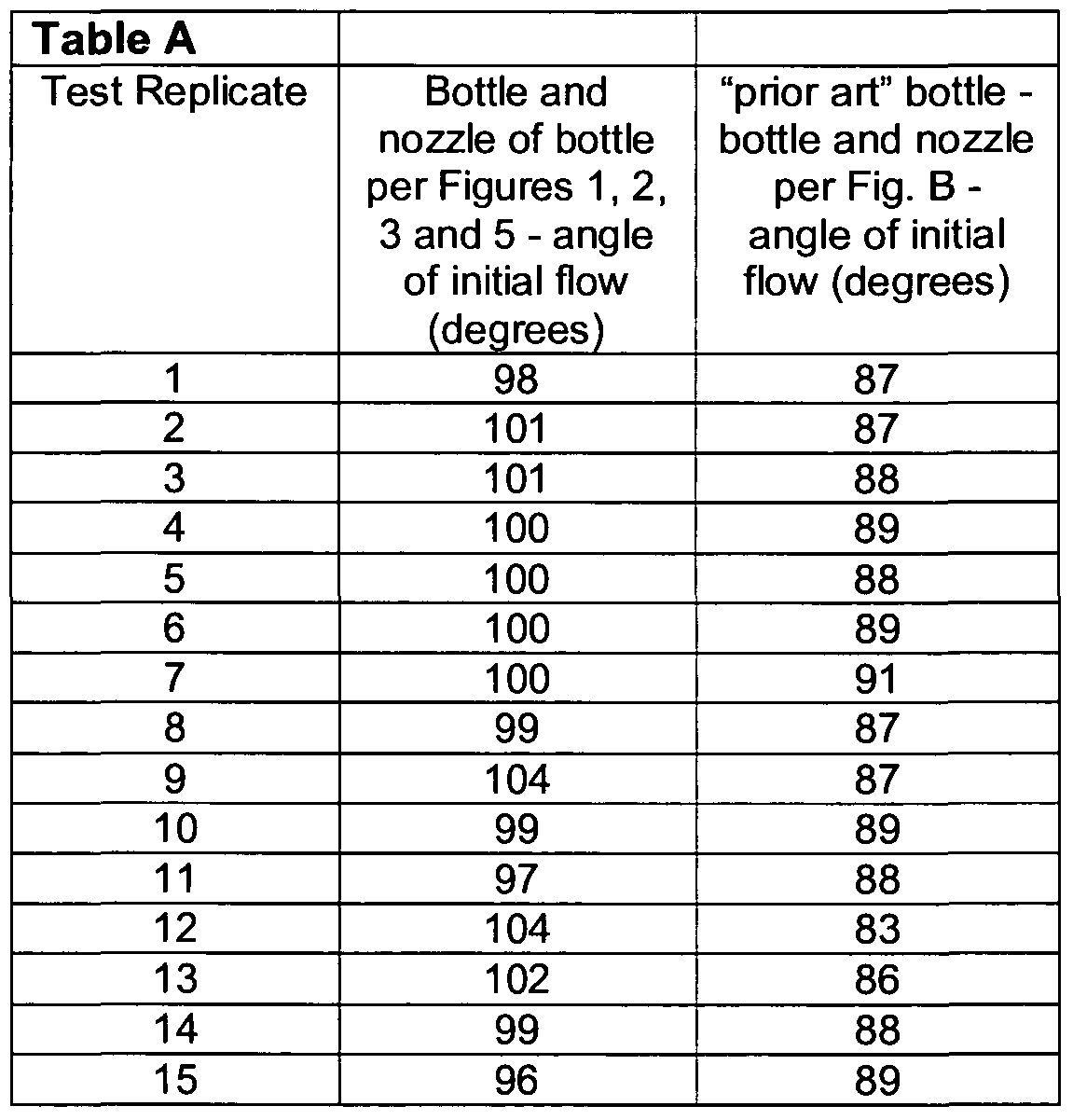
As can be seen from the foregoing, the angle "Z" was greater for the dispensing device according to the invention, viz., bottle and nozzle according to Figures 1, 2, 3 and
5 than using the prior art nozzle with the bottle of Fig. 5. This permitted the user to incline the bottle less in order to initiate dispensing of the treatment composition from the bottle via the nozzle, than the use of the prior art nozzle and bottle, as is depicted with reference to Fig. 6 and Fig. B. In view of the foregoing it will now be understood that in a further aspect the present invention provides an improved method for dispensing a quantity of a liquid treatment composition from a container, such as a dispensing container provided with an improved flow directing nozzle which is adapted to provide improved control over the directional dispensing of a stream of said liquid composition, such as a liquid treatment composition primarily directed to be used for the cleaning and/or disinfecting and/or sanitizing treatment of a lavatory appliance particularly a toilet bowl.
The nozzles of the invention, as well as the dispensing devices may be formed of any suitable material. Advantageously naturally occurring or synthetic polymers provide excellent materials of construction as they are readily molded or otherwise formed into appropriate shapes and configurations. Additionally such polymers are often resistant to the treatment compositions, and particularly with respect to the bottle are resilient and flexible, and thus provide for compressible flasks or bottles. Such are known to the art and include, e.g., any of a number of thermosettable or thermoformable synthetic polymers such as are widely used in casting or injection molding. Exemplary synthetic polymers such as polyamides, polyolefins (e.g., polypropylene, polyethylene) as well as polyalkyleneterephalates (i.e., polyethylene terephthalate, polybutylene terephthalate), polystyrenes, polysulfones, polycarbonates as well as copolymers formed from monomers of one or more of the foregoing being several nonlimiting examples of useful synthetic polymers. Other materials which may be used include metals, glass, elastomeric polymers both naturally occurring and synthetic, as well as any other material which can be suitably shaped or formed into the nozzles of the invention , as well as the dispensing devices.
The dispensing devices of the invention provide a particularly effective device for the effective storage and spray or stream delivery of liquid treatment compositions onto a surface needing treatment by the composition, particularly wherein the dispensing device
is for the directed delivery of a liquid treatment composition to a portion of a toilet bowl, and particularly to the underside of the rim of a toilet bowl.
While described in terms of the presently preferred embodiments, it is to be understood that the present disclosure is to be interpreted as by way of illustration, and not by way of limitation, and that various modifications and alterations apparent to one skilled in the art may be made without departing from the scope and spirit of the present invention.
Claims
1. A flow directing nozzles which comprises: a fluid passage having a central axis which fluid passage is generally in the form of hollow cylindrical shaft having a proximal end, and a distal end from which the liquid treatment composition is dispensed from said that nozzle, said distal end of the fluid passage it is at least partially domed, and includes a fluid outlet which is angled with respect to a central axis of the fluid passage , and a skirt portion which extends radially outwardly from the fluid passage in the form of a generally planar base portion from which extends a skirt sidewall having a geometry which is dimensioned such that the flow directing nozzle is adapted to be inserted into a portion of a container.
2. A flow directing nozzle according to claim 1 wherein: the fluid outlet is an opening defined by a plane crossing the central axis at an angle of between 5°of arc and 85° of arc, and which also intersects the domed portion of the distal end of the fluid passage.
3. A flow directing nozzle according to claim 2 wherein: the fluid outlet is an opening defined by a plane crossing the central axis at an angle of between 20°of arc and 75° of arc, and which also intersects the domed portion of the distal end of the fluid passage.
4. A flow directing nozzle according to claim 3 wherein: the fluid outlet is an opening defined by a plane crossing the central axis at an angle of between 30°of arc and 60° of arc, and which also intersects the domed portion of the distal end of the fluid passage.
5. A flow directing nozzle according to claim 4 wherein: the fluid outlet is an opening defined by a plane crossing the central axis at an angle of between 32°of arc and 45° of arc, and which also intersects the domed portion of the distal end of the fluid passage.
6. A flow directing nozzle according to any preceding claim wherein the radius of the domed end is circular with respect to a point on the central axis of the fluid passage.
7. A flow directing nozzle according to any preceding claim wherein the hollow cylindrical shaft is tapered having an angular taper of between 0.5° of arc and 20° ofarc.
8. A flow directing nozzle according to any preceding claim wherein the diameter or cross-sectional area of the distal end is less than the diameter or cross-sectional area of the proximal end.
9. A container comprising a liquid treatment composition and a flow directing nozzle according to any preceding claim.
10. A method for dispensing a quantity of a liquid treatment composition from a dispensing device which comprises an improved flow directing nozzle according to any of claims 1 — 9.
Applications Claiming Priority (2)
| Application Number | Priority Date | Filing Date | Title |
|---|---|---|---|
| GB0717807A GB0717807D0 (en) | 2007-09-13 | 2007-09-13 | Improvements in liquid dispensing devices |
| GB0717807.2 | 2007-09-13 |
Publications (1)
| Publication Number | Publication Date |
|---|---|
| WO2009034303A1 true WO2009034303A1 (en) | 2009-03-19 |
Family
ID=38658845
Family Applications (1)
| Application Number | Title | Priority Date | Filing Date |
|---|---|---|---|
| PCT/GB2008/003034 Ceased WO2009034303A1 (en) | 2007-09-13 | 2008-09-08 | Improvements in liquid dispensing devices |
Country Status (2)
| Country | Link |
|---|---|
| GB (1) | GB0717807D0 (en) |
| WO (1) | WO2009034303A1 (en) |
Cited By (4)
| Publication number | Priority date | Publication date | Assignee | Title |
|---|---|---|---|---|
| WO2011049616A1 (en) | 2009-10-19 | 2011-04-28 | S. C. Johnson & Son, Inc. | Device for providing cleansing composition to the inner surface of a toilet bowl |
| WO2011049618A1 (en) | 2009-10-19 | 2011-04-28 | S. C. Johnson & Son, Inc. | Non-contact spray toilet bowl cleaning device |
| USD841471S1 (en) | 2017-02-24 | 2019-02-26 | S. C. Johnson & Son, Inc. | Bottle |
| USD845135S1 (en) | 2017-02-24 | 2019-04-09 | S. C. Johnson & Son, Inc. | Bottle neck with cap |
Citations (5)
| Publication number | Priority date | Publication date | Assignee | Title |
|---|---|---|---|---|
| US3837535A (en) * | 1973-02-09 | 1974-09-24 | Formold A Division Of Vca Corp | Plastic dispensing nozzle with reclosable closure cap |
| DE8615534U1 (en) * | 1986-06-09 | 1986-09-25 | Höhn & Höhn GmbH, 5657 Haan | Splash top or insert for a squeeze bottle |
| US4815616A (en) * | 1988-02-29 | 1989-03-28 | The Dow Chemical Company | Angled dispensing closure |
| US5269445A (en) * | 1991-09-17 | 1993-12-14 | Supermatic Kunststoff A.G. | Dispensing device for free-flowing preparations comprising a removable head piece |
| WO2002011895A1 (en) * | 2000-08-08 | 2002-02-14 | Reckitt Benckiser (Brasil) Ltda. | A squeeze bottle dispenser |
-
2007
- 2007-09-13 GB GB0717807A patent/GB0717807D0/en not_active Ceased
-
2008
- 2008-09-08 WO PCT/GB2008/003034 patent/WO2009034303A1/en not_active Ceased
Patent Citations (5)
| Publication number | Priority date | Publication date | Assignee | Title |
|---|---|---|---|---|
| US3837535A (en) * | 1973-02-09 | 1974-09-24 | Formold A Division Of Vca Corp | Plastic dispensing nozzle with reclosable closure cap |
| DE8615534U1 (en) * | 1986-06-09 | 1986-09-25 | Höhn & Höhn GmbH, 5657 Haan | Splash top or insert for a squeeze bottle |
| US4815616A (en) * | 1988-02-29 | 1989-03-28 | The Dow Chemical Company | Angled dispensing closure |
| US5269445A (en) * | 1991-09-17 | 1993-12-14 | Supermatic Kunststoff A.G. | Dispensing device for free-flowing preparations comprising a removable head piece |
| WO2002011895A1 (en) * | 2000-08-08 | 2002-02-14 | Reckitt Benckiser (Brasil) Ltda. | A squeeze bottle dispenser |
Cited By (5)
| Publication number | Priority date | Publication date | Assignee | Title |
|---|---|---|---|---|
| WO2011049616A1 (en) | 2009-10-19 | 2011-04-28 | S. C. Johnson & Son, Inc. | Device for providing cleansing composition to the inner surface of a toilet bowl |
| WO2011049618A1 (en) | 2009-10-19 | 2011-04-28 | S. C. Johnson & Son, Inc. | Non-contact spray toilet bowl cleaning device |
| US8359676B2 (en) | 2009-10-19 | 2013-01-29 | S.C. Johnson & Son, Inc. | Relatively compact non-contact spray toilet bowl cleaning device |
| USD841471S1 (en) | 2017-02-24 | 2019-02-26 | S. C. Johnson & Son, Inc. | Bottle |
| USD845135S1 (en) | 2017-02-24 | 2019-04-09 | S. C. Johnson & Son, Inc. | Bottle neck with cap |
Also Published As
| Publication number | Publication date |
|---|---|
| GB0717807D0 (en) | 2007-10-24 |
Similar Documents
| Publication | Publication Date | Title |
|---|---|---|
| US4550862A (en) | Liquid product pouring and measuring package with self draining feature | |
| EP2296820B1 (en) | Dispensing closure for a fan spray nozzle | |
| EP0109704B1 (en) | Liquid product pouring and measuring package with self draining feature | |
| US8313002B2 (en) | Lid for beverage container | |
| JP2009102071A (en) | Pump head and solution-distributing instrument for volume type pump | |
| US8814010B2 (en) | Fan orifice dispensing closure | |
| WO2009034303A1 (en) | Improvements in liquid dispensing devices | |
| US20080023502A1 (en) | Closure Cap | |
| TWI625282B (en) | Refilling container plug member, refilling method, and refilling container | |
| WO2009034306A1 (en) | Method for manufacturing dispensing devices | |
| US11414248B2 (en) | Dispenser with a membrane for sachets | |
| EP1120354B1 (en) | Package comprising a closure for a liquid container and a refill means, and a method for refilling the package | |
| WO2012063798A1 (en) | Nozzle for liquid medicine container | |
| US20170210521A1 (en) | Closure | |
| EP2476627A1 (en) | Nozzle arrangement fixed on a container | |
| EP0014283B1 (en) | Container for a fluid and a closure member | |
| GB2284202A (en) | Spray type valved dispenser cap | |
| JPS621905B2 (en) | ||
| JP7640968B2 (en) | Containers and dispensed products | |
| US20130032595A1 (en) | Drink containers with unremovable closures | |
| US1104594A (en) | Non-refillable bottle. | |
| WO2003084834A9 (en) | Dispensing article with visual indication of closure | |
| JP2004010054A (en) | Spout plug of liquid storage container |
Legal Events
| Date | Code | Title | Description |
|---|---|---|---|
| 121 | Ep: the epo has been informed by wipo that ep was designated in this application |
Ref document number: 08806209 Country of ref document: EP Kind code of ref document: A1 |
|
| NENP | Non-entry into the national phase |
Ref country code: DE |
|
| 122 | Ep: pct application non-entry in european phase |
Ref document number: 08806209 Country of ref document: EP Kind code of ref document: A1 |