WO2008013159A1 - Noble metal alloy for spark plug and method for producing and processing the same - Google Patents
Noble metal alloy for spark plug and method for producing and processing the same Download PDFInfo
- Publication number
- WO2008013159A1 WO2008013159A1 PCT/JP2007/064482 JP2007064482W WO2008013159A1 WO 2008013159 A1 WO2008013159 A1 WO 2008013159A1 JP 2007064482 W JP2007064482 W JP 2007064482W WO 2008013159 A1 WO2008013159 A1 WO 2008013159A1
- Authority
- WO
- WIPO (PCT)
- Prior art keywords
- noble metal
- metal alloy
- processing
- oxide
- alloy according
- Prior art date
- Legal status (The legal status is an assumption and is not a legal conclusion. Google has not performed a legal analysis and makes no representation as to the accuracy of the status listed.)
- Ceased
Links
Classifications
-
- C—CHEMISTRY; METALLURGY
- C22—METALLURGY; FERROUS OR NON-FERROUS ALLOYS; TREATMENT OF ALLOYS OR NON-FERROUS METALS
- C22C—ALLOYS
- C22C5/00—Alloys based on noble metals
-
- C—CHEMISTRY; METALLURGY
- C22—METALLURGY; FERROUS OR NON-FERROUS ALLOYS; TREATMENT OF ALLOYS OR NON-FERROUS METALS
- C22F—CHANGING THE PHYSICAL STRUCTURE OF NON-FERROUS METALS AND NON-FERROUS ALLOYS
- C22F1/00—Changing the physical structure of non-ferrous metals or alloys by heat treatment or by hot or cold working
- C22F1/14—Changing the physical structure of non-ferrous metals or alloys by heat treatment or by hot or cold working of noble metals or alloys based thereon
-
- C—CHEMISTRY; METALLURGY
- C23—COATING METALLIC MATERIAL; COATING MATERIAL WITH METALLIC MATERIAL; CHEMICAL SURFACE TREATMENT; DIFFUSION TREATMENT OF METALLIC MATERIAL; COATING BY VACUUM EVAPORATION, BY SPUTTERING, BY ION IMPLANTATION OR BY CHEMICAL VAPOUR DEPOSITION, IN GENERAL; INHIBITING CORROSION OF METALLIC MATERIAL OR INCRUSTATION IN GENERAL
- C23C—COATING METALLIC MATERIAL; COATING MATERIAL WITH METALLIC MATERIAL; SURFACE TREATMENT OF METALLIC MATERIAL BY DIFFUSION INTO THE SURFACE, BY CHEMICAL CONVERSION OR SUBSTITUTION; COATING BY VACUUM EVAPORATION, BY SPUTTERING, BY ION IMPLANTATION OR BY CHEMICAL VAPOUR DEPOSITION, IN GENERAL
- C23C26/00—Coating not provided for in groups C23C2/00 - C23C24/00
- C23C26/02—Coating not provided for in groups C23C2/00 - C23C24/00 applying molten material to the substrate
-
- C—CHEMISTRY; METALLURGY
- C23—COATING METALLIC MATERIAL; COATING MATERIAL WITH METALLIC MATERIAL; CHEMICAL SURFACE TREATMENT; DIFFUSION TREATMENT OF METALLIC MATERIAL; COATING BY VACUUM EVAPORATION, BY SPUTTERING, BY ION IMPLANTATION OR BY CHEMICAL VAPOUR DEPOSITION, IN GENERAL; INHIBITING CORROSION OF METALLIC MATERIAL OR INCRUSTATION IN GENERAL
- C23C—COATING METALLIC MATERIAL; COATING MATERIAL WITH METALLIC MATERIAL; SURFACE TREATMENT OF METALLIC MATERIAL BY DIFFUSION INTO THE SURFACE, BY CHEMICAL CONVERSION OR SUBSTITUTION; COATING BY VACUUM EVAPORATION, BY SPUTTERING, BY ION IMPLANTATION OR BY CHEMICAL VAPOUR DEPOSITION, IN GENERAL
- C23C6/00—Coating by casting molten material on the substrate
-
- H—ELECTRICITY
- H01—ELECTRIC ELEMENTS
- H01T—SPARK GAPS; OVERVOLTAGE ARRESTERS USING SPARK GAPS; SPARKING PLUGS; CORONA DEVICES; GENERATING IONS TO BE INTRODUCED INTO NON-ENCLOSED GASES
- H01T13/00—Sparking plugs
- H01T13/20—Sparking plugs characterised by features of the electrodes or insulation
- H01T13/39—Selection of materials for electrodes
-
- H—ELECTRICITY
- H01—ELECTRIC ELEMENTS
- H01T—SPARK GAPS; OVERVOLTAGE ARRESTERS USING SPARK GAPS; SPARKING PLUGS; CORONA DEVICES; GENERATING IONS TO BE INTRODUCED INTO NON-ENCLOSED GASES
- H01T21/00—Apparatus or processes specially adapted for the manufacture or maintenance of spark gaps or sparking plugs
- H01T21/02—Apparatus or processes specially adapted for the manufacture or maintenance of spark gaps or sparking plugs of sparking plugs
-
- B—PERFORMING OPERATIONS; TRANSPORTING
- B22—CASTING; POWDER METALLURGY
- B22F—WORKING METALLIC POWDER; MANUFACTURE OF ARTICLES FROM METALLIC POWDER; MAKING METALLIC POWDER; APPARATUS OR DEVICES SPECIALLY ADAPTED FOR METALLIC POWDER
- B22F2998/00—Supplementary information concerning processes or compositions relating to powder metallurgy
- B22F2998/10—Processes characterised by the sequence of their steps
Definitions
- the present invention relates to a noble metal alloy suitable as a material for a noble metal tip attached to the tip of a center electrode of a spark plug.
- a suitable method for producing and processing a noble metal alloy is provided.
- a spark plug used in an internal combustion engine such as an automobile has a noble metal tip fixed to its tip for the purpose of improving the durability of the center electrode.
- Particularly useful as a material for this noble metal tip is iridium or an alloy thereof.
- Patent Document 1 describes a noble metal tip made of iridium
- Patent Document 2 describes a noble metal tip made of an alloy of iridium and nickel.
- Patent Document 1 JP-A-5-54955
- Patent Document 2 JP-A-1 319284
- Precious metal tips are used for the purpose of improving durability, but their constituent materials are required to be excellent in resistance to sparks, resistance to oxidation and chemicals. Since the spark plug causes combustion in the internal combustion engine by sparks, it is exposed to impacts from sparks and high-temperature, high-oxidation atmospheres, and also comes into contact with chemicals such as fuel and oil additives. Because.
- iridium and iridium alloys which are materials for precious metal chips, have been considered to satisfy the above-mentioned characteristics for a long time. You need something. In particular, when it comes to oxidation resistance, iridium is a chemically stable force S, yet it cannot suppress the progress of oxidation in the environment where the spark plug is used. The iridium oxide generated by the oxidation of iridium volatilizes at a high temperature, so that the noble metal tip is consumed due to long-term use. Obedience Therefore, it is necessary to take measures against consumption due to such oxidation.
- an object of the present invention is to provide a material for a noble metal tip of a spark plug, which is superior in durability and particularly in oxidation resistance consumption as compared with the prior art.
- the present invention for solving the above-mentioned problems is for a spark plug containing 0.2 to 6.0 wt% of Cr as an essential component, and further containing at least one of Fe and Ni, with the balance being Ir.
- This is a noble metal alloy.
- the present invention is a noble metal alloy in which Cr and Fe or Cr and Ni or Cr and Fe and Ni are alloyed with Ir, and when this alloy is oxidized, a Cr—Fe oxide or Cr—Ni is formed on the surface. A film composed of a series oxide or Cr — Fe—Ni series oxide is formed. Since this oxide film does not disappear even at high temperatures that are not volatile in the environment in which the plug is used, it is possible to suppress the consumption of the iridium alloy as a base material, and long-term use. It becomes possible.
- the Ir alloy according to the present invention has the characteristics of the oxide film to be formed and the resistance to wear under a high-temperature oxidizing atmosphere due to the self-healing action of the film based on the diffusion phenomenon therein. Excellent. And since these actions are greatly related to the presence of Cr, Cr is an essential constituent!
- the composition of the Ir alloy according to the present invention is such that Cr, which is an essential component, is 0.2 to 6.0% by weight. This is because when the amount is less than 0.2% by weight, the above-mentioned effect is not exhibited. When the amount exceeds 6.0%, the melting point of the alloy is lowered and the spark wear resistance is affected. Cr is 0.5 It is preferable to set it to -6.0 weight%. This is because it is easy to form a stronger oxide film.
- 12.0% by weight is preferable 5.0-12.0% by weight is more preferable. This is because if these additive elements are less than 2.0% by weight, an oxide film having a sufficient thickness cannot be formed. If it exceeds 12.0% by weight, the spark wear resistance is affected. This is because the workability is remarkably deteriorated. On the other hand, if it is 5.0% by weight or more, the oxide film is formed to a sufficient thickness, and iridium oxidation consumption can be effectively prevented.
- the Ir alloy according to the present invention preferably further contains 0.5 to 15% by weight of Rh (rhodium). This is because the discharge voltage of the spark plug is suppressed and the workability of the noble metal alloy is improved. If the amount of Rh added is less than 0.5% by weight, it is not desired to improve the workability, and if it is added more than 15% by weight, there is no particular problem. Because it becomes.
- the spark plug made of an Ir alloy manufactured and processed by the above method is used in a high-temperature, high-oxidation atmosphere, the noble metal tip made of the alloy according to the present invention immediately has the above-described action on the surface during use. An oxide film is formed.
- the Ir alloy according to the present invention one having an oxide layer formed in advance can also be used.
- the oxide layer formed by the diffusion treatment preferably has a thickness of 5 to 100111. This is because if it is less than 5 m, it has no protective action, and if it exceeds 100 m, it is easy to peel off due to impact or the like. A more preferable range of the thickness of the oxide layer is 10 to 50 111.
- the Ir alloy according to the present invention can be manufactured by mixing constituent metals and performing melting and forging. After the obtained Ir alloy is used as a sheet material or wire, a desired length is obtained. It can be used as a spark plug by processing it into a noble metal tip by a method such as cutting.
- a force S can be obtained by heating and melting the raw material charged in the crucible with a high energy beam such as arc melting.
- a high energy beam such as arc melting.
- melting by high energy beam irradiation has a large capacity of raw materials. If it is not, it is difficult to uniformly dissolve the whole, and it may be difficult to make the alloy composition uniform.
- the plug material that is the object of the noble metal alloy according to the present invention is manufactured from a long wire, but in order to manufacture a long wire, it is necessary to melt and produce a corresponding amount of raw materials.
- two or more marble ingots having a small diameter are manufactured by melting and forming powder or small pieces made of metal constituting the alloy by a high frequency induction heating method, The marble ingots were brought into contact with each other, and the contact portions were melted and joined to be integrated, and the integrated ingot was plastic processed.
- the high-frequency induction heating method is a method in which a raw material to be melted is introduced into a high-frequency coil, a coil is energized, and the raw material is melted by induction heating.
- the raw material in the coil can be melted in the same way, and a high-quality marble ingot without segregation can be produced.
- the basic configuration of the apparatus used in the manufacturing process of the present invention is an AC power source and a coil.
- oxides such as graphite, alumina, magnesia, and force lucia are used as crucibles that contain raw materials. Can be used.
- the power output is set to 1 to OOkW depending on the composition of the raw materials to be melted.
- the frequency is set according to the size of the raw material. In the production of marble ingots, a frequency of 30 to 500 kHz force S is preferable.
- As the coil a copper pipe is used, and a coil having a water cooling mechanism is used.
- a flotation melting and forging method can be used as the high-frequency induction heating method.
- the levitation melting method is a method in which a coil is energized using a water-cooled copper crucible and melted in a state where the raw material is floated by the Lorentz force generated between the eddy current induced in the copper crucible and the eddy current flowing through the raw material. is there. According to this method, a high-purity ingot can be produced in which the melted raw material does not come into contact with the crucible.
- the size of the marble ingot is preferably 5 to 500 g! /. If it is less than 5 g, a large number of marble ingots must be manufactured, and it is difficult to manufacture a product exceeding 500 g by the high frequency induction heating method because of the capability of the apparatus.
- an appropriate mold for the work of integrating a plurality of marble ingots, it is preferable to use an appropriate mold (saddle mold).
- the internal shape of the mold is preferably a rod-shaped one, and the ratio of the square root to the length of the cross-sectional area (aspect ratio) is from 1: 3 to 1:20!
- the method of melting the contact portions of the plurality of marble ingots is preferably an arc melting method for the sake of convenience, preferably by heating with a high energy beam such as a laser or electron beam. it can.
- plastic working can be performed by one or more processes of forging, rolling, swaging caloe, and drawing.
- the rolling process includes not only rolling with a flat roll but also groove rolling with a grooved roll.
- the processing for forming the wire can be performed by a known method such as hot swaging. Heat treatment may be performed during the processing.
- the processing temperature (hot and cold) during processing can be appropriately selected according to the processing rate and the like.
- heat treatment may be performed between the steps.
- the heat treatment is performed for the purpose of adjusting the crystal structure and removing processing strain.
- the marble ingot is integrated, hot forged and then heat treated, and the entire joint and melted parts are uniform.
- rolling or the like can be performed to suppress material breakage and defect introduction due to processing.
- This heat treatment is also often performed at a force of 800 to 1700 ° C depending on the composition of the target material, recrystallization temperature, and the like.
- FIG. 1 is a photograph showing a material structure of a cross section of a wire manufactured and processed in the present embodiment.
- FIG. 2 is a photograph showing a cross section of a noble metal tip according to Example 6.
- Ir Cr Fe alloy, Ir Cr Ni alloy, and Ir—Cr—Fe—Ni alloy having various compositions were produced, and oxidation resistance and wear resistance were evaluated.
- Each alloy was manufactured by the following method.
- Ir, Cr, Fe, Ni, Rh small pieces (dimensions: 2 mm to 10 mm) were prepared as raw materials, and loaded into a water-cooled copper mold so that the alloy composition shown in Table 1 was obtained. Then, it was dissolved and fabricated in an inert gas by a high-frequency induction heating method (floating dissolution method). Dissolution conditions: output 50kW, frequency 250 The whole alloy was melted to achieve a uniform composition at kHz. After the alloy was melted, the output was controlled and gradually cooled at a cooling rate of 200 ° C / min to discharge the residual gas to produce a marble ingot (diameter 15 mm, thickness 8 mm) without voids.
- a high-frequency induction heating method floating dissolution method
- the marble ingot was integrated, it was hot forged at 1500 ° C and formed into a 12mm square ingot. After that, groove rolling, swaging caloe, and die drawing were performed to obtain a wire with a diameter of 0.6 mm. In these processing steps, heat treatment was performed at 1400 ° C in nitrogen at a stage where the cross-section reduction rate was 20% force and 30%. A noble metal tip having a length of 0.8 mm was cut out from this wire.
- Figure 1 shows the material structure of the cross-section of the wire after processing.
- the oxidation consumption resistance of the manufactured noble metal tip was evaluated.
- some noble metal chips were subjected to diffusion treatment before evaluation to form an oxide film in advance. This treatment was performed by heating the chip at 500 ° C for 1 hour in the atmosphere.
- the oxidation resistance of the noble metal tip was evaluated by heating the tip in air at 1300 ° C for 10 hours, measuring the mass change during the heating process with TG-DTA, and determining the mass change per hour. evaluated. In addition, the appearance of the chip after the test was observed to examine the presence or absence of wear.
- Table 1 shows a comparison of the evaluation results of noble metal tips made of Ir, Ir-Ni alloy, and Ir-Fe alloy as conventional technologies.
- the precious metal tip made of an Ir alloy of! ⁇ 8 manufactured in this embodiment with Cr as an essential component is used in a high-temperature oxidizing atmosphere with extremely low mass loss. It was confirmed that the wear resistance was excellent. Also, the appearance was relatively smooth although there was a change in hue. On the other hand, when Cr is not contained as in Comparative Examples 1 to 3, or when the Cr content exceeds the range of 0.2 to 6.0% by weight as in Comparative Examples 4 and 5, mass loss occurs. As soon as this occurred, the appearance became extremely rough.
- FIG. 2 shows a photograph of the noble metal tip of Example 6 after the evaluation test and quantitative analysis values at various places.
- the noble metal tip of Example 6 has a surface after oxidation. It can be seen that there is a ternary oxide film formed on and a layer enriched with Fe and Cr as an intermediate layer.
- the Ir alloy according to the present invention can form an oxide film excellent in the protective effect of the base material by the action of Cr in the alloy, and in particular, the resistance to oxidation and consumption. Excellent.
- the Cr concentration within an appropriate range, other durability such as spark wear resistance is ensured to be equal to or higher than that of conventional materials. Therefore, by providing the center electrode with the noble metal tip made of the Ir alloy according to the present invention, the life of the spark plug can be extended.
Landscapes
- Chemical & Material Sciences (AREA)
- Engineering & Computer Science (AREA)
- Materials Engineering (AREA)
- Mechanical Engineering (AREA)
- Metallurgy (AREA)
- Organic Chemistry (AREA)
- Chemical Kinetics & Catalysis (AREA)
- Physics & Mathematics (AREA)
- Thermal Sciences (AREA)
- Crystallography & Structural Chemistry (AREA)
- Manufacturing & Machinery (AREA)
- Spark Plugs (AREA)
Abstract
Description
明 細 書 Specification
スパークプラグ用の貴金属合金及びその製造カ卩ェ方法 Noble metal alloy for spark plug and method for manufacturing the same
技術分野 Technical field
[0001] 本発明は、スパークプラグの中心電極の先端部に取り付けられる貴金属チップの 材料として好適な貴金属合金に関する。また、貴金属合金の好適な製造加工方法を 提供する。 The present invention relates to a noble metal alloy suitable as a material for a noble metal tip attached to the tip of a center electrode of a spark plug. In addition, a suitable method for producing and processing a noble metal alloy is provided.
背景技術 Background art
[0002] 自動車等の内燃機関で使用されるスパークプラグには、中心電極の耐久性向上を 目的として、その先端部に貴金属チップが固定されている。この貴金属チップの材料 として、特に有用なのはイリジウム又はその合金である。例えば、特許文献 1には、ィ リジゥムからなる貴金属チップが記載されており、また、特許文献 2ではイリジウムと二 ッケルとの合金からなる貴金属チップが記載されている。 [0002] A spark plug used in an internal combustion engine such as an automobile has a noble metal tip fixed to its tip for the purpose of improving the durability of the center electrode. Particularly useful as a material for this noble metal tip is iridium or an alloy thereof. For example, Patent Document 1 describes a noble metal tip made of iridium, and Patent Document 2 describes a noble metal tip made of an alloy of iridium and nickel.
特許文献 1 :特開平 5— 54955号公報 Patent Document 1: JP-A-5-54955
特許文献 2:特開平 1 319284号公報 Patent Document 2: JP-A-1 319284
[0003] 貴金属チップは、耐久性向上の目的で使用されるものであるが、その構成材料に は、耐火花消耗性、耐酸化消耗性、耐薬品性に優れていることが要求される。スパー クプラグは、火花により内燃機関内の燃焼を生じさせるものであることから、火花によ る衝撃や高温高酸化性雰囲気に曝され、更に、燃料、オイル添加剤等の化学薬品 にも接触するからである。 [0003] Precious metal tips are used for the purpose of improving durability, but their constituent materials are required to be excellent in resistance to sparks, resistance to oxidation and chemicals. Since the spark plug causes combustion in the internal combustion engine by sparks, it is exposed to impacts from sparks and high-temperature, high-oxidation atmospheres, and also comes into contact with chemicals such as fuel and oil additives. Because.
発明の開示 Disclosure of the invention
発明が解決しょうとする課題 Problems to be solved by the invention
[0004] 従来から貴金属チップ用の材料であるイリジウム、イリジウム合金は、上記の諸特性 を一応満足するものとされていた力 スパークプラグの更なる長寿命化への要望を考 えれば、より優れたものが必要となる。特に、耐酸化特性に関して言えば、イリジウム は化学的に安定ではある力 S、それでも、スパークプラグの使用環境においては酸化 の進行を抑制することはできない。そして、イリジウムの酸化により生じる酸化イリジゥ ムは、高温下で揮発するため長期使用に伴う貴金属チップは消耗することとなる。従 つて、このような酸化に伴う消耗に対する対策が必要となる。 [0004] Conventionally, iridium and iridium alloys, which are materials for precious metal chips, have been considered to satisfy the above-mentioned characteristics for a long time. You need something. In particular, when it comes to oxidation resistance, iridium is a chemically stable force S, yet it cannot suppress the progress of oxidation in the environment where the spark plug is used. The iridium oxide generated by the oxidation of iridium volatilizes at a high temperature, so that the noble metal tip is consumed due to long-term use. Obedience Therefore, it is necessary to take measures against consumption due to such oxidation.
[0005] そこで、本発明は、スパークプラグの貴金属チップ用の材料であって、従来よりも耐 久性、特に耐酸化消耗性に優れるものを提供することを課題とする。 [0005] Accordingly, an object of the present invention is to provide a material for a noble metal tip of a spark plug, which is superior in durability and particularly in oxidation resistance consumption as compared with the prior art.
課題を解決するための手段 Means for solving the problem
[0006] 上記課題を解決する本発明は、必須成分として Crを 0. 2〜6. 0重量%含有し、更 に、 Fe、 Niの少なくともいずれかを含み、残部が Irからなるスパークプラグ用の貴金 属合金である。 [0006] The present invention for solving the above-mentioned problems is for a spark plug containing 0.2 to 6.0 wt% of Cr as an essential component, and further containing at least one of Fe and Ni, with the balance being Ir. This is a noble metal alloy.
[0007] 本発明では、イリジウムへ合金化する元素として、 Cr (クロム)を必須の成分とし、更 に Fe (鉄)、 Ni (ニッケル)の少なくともいずれかを含むイリジウム合金である。本発明 は、 Crと Fe又は Crと Ni若しくは Crと Feと Niとを Irに合金化した貴金属合金であり、こ の合金は酸化したときに、表面に Cr— Fe系酸化物又は Cr— Ni系酸化物若しくは Cr — Fe— Ni系酸化物からなる皮膜が形成される。この酸化物皮膜は、プラグの使用環 境下では揮発性を有するものではなぐ高温下においても消失することはないため、 基材となるイリジウム合金の消耗を抑制することができ、長期の使用が可能となる。 [0007] In the present invention, an iridium alloy containing Cr (chromium) as an essential component and further containing at least one of Fe (iron) and Ni (nickel) as an element to be alloyed with iridium. The present invention is a noble metal alloy in which Cr and Fe or Cr and Ni or Cr and Fe and Ni are alloyed with Ir, and when this alloy is oxidized, a Cr—Fe oxide or Cr—Ni is formed on the surface. A film composed of a series oxide or Cr — Fe—Ni series oxide is formed. Since this oxide film does not disappear even at high temperatures that are not volatile in the environment in which the plug is used, it is possible to suppress the consumption of the iridium alloy as a base material, and long-term use. It becomes possible.
[0008] また、上記の酸化物皮膜の形成過程においては、合金中の Cr、 Fe、 Niが合金表 面に拡散し、これにより Irを含めた表面上の各元素が酸化して皮膜を形成する。その ため、酸化物層と基材である Ir合金との間には、 Irマトリックス中に酸素と共に Cr、 Fe 、 Niが富化された中間層が形成される。この中間層は完全な酸化物である皮膜の密 着性を確保すると共に、皮膜が消失した場合の新たな酸化物の供給源となる。即ち、 仮に振動、衝撃等により酸化物皮膜が、部分的に或いは大部分が剥離しても、中間 層が直ちに酸化物となりその消耗を抑制することができる。 [0008] In the above oxide film formation process, Cr, Fe, and Ni in the alloy diffuse to the alloy surface, and each element on the surface including Ir is oxidized to form a film. To do. Therefore, an intermediate layer enriched with Cr, Fe, and Ni together with oxygen in the Ir matrix is formed between the oxide layer and the base Ir alloy. This intermediate layer ensures the adhesion of the film, which is a complete oxide, and provides a new source of oxide when the film disappears. That is, even if the oxide film is partially or largely peeled off due to vibration, impact, etc., the intermediate layer immediately becomes an oxide and its consumption can be suppressed.
[0009] 以上のように、本発明に係る Ir合金は、形成される酸化物皮膜の特性、及び、その 内部の拡散現象に基づく皮膜の自己修復作用により、高温酸化雰囲気下での耐消 耗特性に優れる。そして、これらの作用は Crの存在が大きく関与していることから、 C rは必須の構成成分として!/、る。 [0009] As described above, the Ir alloy according to the present invention has the characteristics of the oxide film to be formed and the resistance to wear under a high-temperature oxidizing atmosphere due to the self-healing action of the film based on the diffusion phenomenon therein. Excellent. And since these actions are greatly related to the presence of Cr, Cr is an essential constituent!
[0010] ここで、本発明に係る Ir合金の組成は、必須成分である Crは、 0. 2〜6. 0重量%と する。 0. 2重量%未満では、上記の作用を発揮しないからであり、 6. 0%を超えると 、合金の融点が低下し耐火花消耗性に影響を及ぼすからである。また、 Crは、 0. 5 〜6. 0重量%とすることが好ましい。より強固な酸化膜を形成しやすいからである。 Here, the composition of the Ir alloy according to the present invention is such that Cr, which is an essential component, is 0.2 to 6.0% by weight. This is because when the amount is less than 0.2% by weight, the above-mentioned effect is not exhibited. When the amount exceeds 6.0%, the melting point of the alloy is lowered and the spark wear resistance is affected. Cr is 0.5 It is preferable to set it to -6.0 weight%. This is because it is easy to form a stronger oxide film.
[0011] 一方、 Fe、 Niのいずれか又は双方を添加する場合、その添加量は、合計で 2· 0〜 [0011] On the other hand, when either or both of Fe and Ni are added, the total amount added is 2.0 ·
12. 0重量%とするのが好ましぐ 5. 0-12. 0重量%とするのが、さらに好ましい。こ れらの添加元素が 2. 0重量%未満であると、十分な厚さの酸化物皮膜が形成されな いからであり、 12. 0重量%を超えると、耐火花消耗性に影響を及ぼすと共に加工性 が著しく低下するからである。また、 5. 0重量%以上であると、酸化膜が十分な厚さ に形成され、イリジウムの酸化消耗を効果的に防ぐことが出来る。 12.0% by weight is preferable 5.0-12.0% by weight is more preferable. This is because if these additive elements are less than 2.0% by weight, an oxide film having a sufficient thickness cannot be formed. If it exceeds 12.0% by weight, the spark wear resistance is affected. This is because the workability is remarkably deteriorated. On the other hand, if it is 5.0% by weight or more, the oxide film is formed to a sufficient thickness, and iridium oxidation consumption can be effectively prevented.
[0012] 本発明に係る Ir合金は、更に、 0. 5〜; 15重量%の Rh (ロジウム)を含有することも 好ましい。スパークプラグの放電電圧の上昇を抑えるとともに、貴金属合金の加工性 が向上するからである。 Rhの添加量は、 0. 5重量%未満では、加工性の向上が望ま れず、 15重量%より多く含有しても特に問題はないが、加工性は向上しにくい傾向と なる一方、高コストになるためである。 [0012] The Ir alloy according to the present invention preferably further contains 0.5 to 15% by weight of Rh (rhodium). This is because the discharge voltage of the spark plug is suppressed and the workability of the noble metal alloy is improved. If the amount of Rh added is less than 0.5% by weight, it is not desired to improve the workability, and if it is added more than 15% by weight, there is no particular problem. Because it becomes.
[0013] 上記方法により製造及び加工した Ir合金からなるスパークプラグは、高温、高酸化 雰囲気で使用されることから、本発明に係る合金からなる貴金属チップは、使用時に 直ちに表面に上記の作用により酸化物皮膜が形成される。 [0013] Since the spark plug made of an Ir alloy manufactured and processed by the above method is used in a high-temperature, high-oxidation atmosphere, the noble metal tip made of the alloy according to the present invention immediately has the above-described action on the surface during use. An oxide film is formed.
[0014] また、本発明に係る Ir合金は、予め酸化物層が形成されたものも使用できる。この 場合、 Ir合金を酸化雰囲気中、 300〜900°Cで加熱する拡散処理を行なうことで、 C ー?6系酸化物又は ー^系酸化物若しくは ー?6— ^系酸化物からなる酸化 物皮膜が形成される。このように拡散処理により形成される酸化物層は、その厚さが 5 〜100 111のものが好ましい。 5 m未満であると保護作用を有しないからであり、 10 0 mを超えると衝撃などにより剥離しやすくなるからである。酸化物層の厚さのより 好ましい範囲は、 10〜50 111である。 [0014] As the Ir alloy according to the present invention, one having an oxide layer formed in advance can also be used. In this case, it is possible to perform diffusion treatment by heating the Ir alloy at 300 to 900 ° C in an oxidizing atmosphere. 6-type oxide or-^-type oxide or-? An oxide film composed of 6 — ^-based oxide is formed. Thus, the oxide layer formed by the diffusion treatment preferably has a thickness of 5 to 100111. This is because if it is less than 5 m, it has no protective action, and if it exceeds 100 m, it is easy to peel off due to impact or the like. A more preferable range of the thickness of the oxide layer is 10 to 50 111.
[0015] そして、本発明に係る Ir合金は、構成金属を混合し、溶解'铸造を行うことで製造す ること力 Sでき、得られた Ir合金を板材ゃ線材とした後、所望の長さに切断する方法等 によって貴金属チップに加工して、スパークプラグとして使用可能となる。 [0015] The Ir alloy according to the present invention can be manufactured by mixing constituent metals and performing melting and forging. After the obtained Ir alloy is used as a sheet material or wire, a desired length is obtained. It can be used as a spark plug by processing it into a noble metal tip by a method such as cutting.
[0016] 本発明に係る高融点の貴金属合金を溶解 ·铸造する方法としては、坩堝に投入し た原材料を、アーク溶解等の高エネルギービームによって加熱溶解させる方法によ ること力 Sできる。しかし、高エネルギービーム照射による溶解は、原材料の容量が多 い場合、全体を均一に溶解させることが困難であり、合金組成を均一化しにくい場合 がある。特に、本発明に係る貴金属合金の対象となるプラグ材料は、長尺の線材から 製造されるが、長尺の線材を製造するためには相応の量の原材料を溶解'铸造する 必要がある。 [0016] As a method for melting and forging a noble metal alloy having a high melting point according to the present invention, a force S can be obtained by heating and melting the raw material charged in the crucible with a high energy beam such as arc melting. However, melting by high energy beam irradiation has a large capacity of raw materials. If it is not, it is difficult to uniformly dissolve the whole, and it may be difficult to make the alloy composition uniform. In particular, the plug material that is the object of the noble metal alloy according to the present invention is manufactured from a long wire, but in order to manufacture a long wire, it is necessary to melt and produce a corresponding amount of raw materials.
[0017] そこで、本発明に係る Ir合金の製造加工方法では、合金を構成する金属からなる 粉末又は小片を高周波誘導加熱法により溶解 '铸造し小径のマーブル状インゴットを 2個以上製造し、前記マーブル状インゴットを相互に当接させると共に、接触部を溶 解させて接合して一体化し、一体化したインゴットを塑性加工することとした。 [0017] Therefore, in the Ir alloy manufacturing and processing method according to the present invention, two or more marble ingots having a small diameter are manufactured by melting and forming powder or small pieces made of metal constituting the alloy by a high frequency induction heating method, The marble ingots were brought into contact with each other, and the contact portions were melted and joined to be integrated, and the integrated ingot was plastic processed.
[0018] 高周波誘導加熱法は、高周波コイルの内部へ溶解対象となる原材料を導入してコ ィルへ通電し、誘導加熱により原材料を溶解するものである。コイル内の原材料を一 様に溶解でき、偏析等のない高品質のマーブル状インゴットを製造できる。複数のマ 一ブル状インゴットを溶解 .接合し加ェすることにより、組成'組織の均一性を維持し た線材等が得られる。 [0018] The high-frequency induction heating method is a method in which a raw material to be melted is introduced into a high-frequency coil, a coil is energized, and the raw material is melted by induction heating. The raw material in the coil can be melted in the same way, and a high-quality marble ingot without segregation can be produced. By melting, joining, and adding a plurality of mull-shaped ingots, it is possible to obtain a wire or the like that maintains the compositional uniformity of the structure.
[0019] 本発明の製造工程に用いる装置の基本的構成は、交流電源、コイルであり、铸造 には、原材料を収容する坩堝として、グラフアイトやアルミナ、マグネシア、力ルシア等 の酸化物等を使用できる。溶解工程は、溶解する原材料の組成により、電源の出力 を 1〜; !OOkWとする。周波数は、原材料のサイズによって設定するものであり、マー ブル状インゴットの製造では、周波数 30〜500kHz力 S好ましい。コイルは、銅製のパ イブを成形したものが用いられ、水冷機構を有するものが用いられる。 [0019] The basic configuration of the apparatus used in the manufacturing process of the present invention is an AC power source and a coil. For fabrication, oxides such as graphite, alumina, magnesia, and force lucia are used as crucibles that contain raw materials. Can be used. In the melting process, the power output is set to 1 to OOkW depending on the composition of the raw materials to be melted. The frequency is set according to the size of the raw material. In the production of marble ingots, a frequency of 30 to 500 kHz force S is preferable. As the coil, a copper pipe is used, and a coil having a water cooling mechanism is used.
[0020] また、高周波誘導加熱法として浮揚溶解铸造法を用いることができる。浮揚溶解铸 造法は、水冷銅坩堝を用いてコイルに通電し、銅坩堝に誘起する渦電流と原材料を 流れる渦電流との間で生じるローレンツ力により原材料を浮揚させた状態で溶解する 方法である。この方法によれば、溶解した原材料が坩堝と接触することなぐ高純度 のインゴットを製造できる。 [0020] Further, a flotation melting and forging method can be used as the high-frequency induction heating method. The levitation melting method is a method in which a coil is energized using a water-cooled copper crucible and melted in a state where the raw material is floated by the Lorentz force generated between the eddy current induced in the copper crucible and the eddy current flowing through the raw material. is there. According to this method, a high-purity ingot can be produced in which the melted raw material does not come into contact with the crucible.
[0021] 高周波誘導加熱法による铸造では、マーブル状インゴットの大きさを 5〜500gとす るのが好まし!/、。 5g未満では多数のマーブル状インゴットを製造しなければならず煩 雑となり、 500gを超えるものを高周波誘導加熱法で製造するのは装置の能力等の 関係から困難だからである。 [0022] 複数のマーブル状インゴットを一体化する作業には、適宜の型 (铸型)を用いるの が好ましい。型の内部形状は棒状のものが好ましぐその断面積の平方根と長さとの 比(アスペクト比)が 1: 3〜; 1: 20となって!/、るものが好ましレ、。マーブル状インゴットを 一体化する際、複数のマーブル状インゴットの接触部分を溶解させる方法としては、 レーザー、電子ビーム等の高エネルギービーム加熱によるものが好ましぐ便宜的に アーク溶解法も用いることができる。 [0021] In the forging by the high frequency induction heating method, the size of the marble ingot is preferably 5 to 500 g! /. If it is less than 5 g, a large number of marble ingots must be manufactured, and it is difficult to manufacture a product exceeding 500 g by the high frequency induction heating method because of the capability of the apparatus. [0022] For the work of integrating a plurality of marble ingots, it is preferable to use an appropriate mold (saddle mold). The internal shape of the mold is preferably a rod-shaped one, and the ratio of the square root to the length of the cross-sectional area (aspect ratio) is from 1: 3 to 1:20! When the marble ingots are integrated, the method of melting the contact portions of the plurality of marble ingots is preferably an arc melting method for the sake of convenience, preferably by heating with a high energy beam such as a laser or electron beam. it can.
[0023] マーブル状インゴットを一体化した後は、鍛造加工、圧延加工、スウェージングカロェ 、引き抜き加工の 1以上の工程による塑性加工が可能である。圧延加工は、平ロール による圧延の他、溝付ロールによる溝圧延を含む。線材にするための加工は、熱間ス ゥエージング等の公知の方法で行うことができる。加工途中で熱処理を行っても良い 。加工時の加工温度(熱間、冷間)は、加工率等に応じて適宜選択できる。 [0023] After the marble ingot is integrated, plastic working can be performed by one or more processes of forging, rolling, swaging caloe, and drawing. The rolling process includes not only rolling with a flat roll but also groove rolling with a grooved roll. The processing for forming the wire can be performed by a known method such as hot swaging. Heat treatment may be performed during the processing. The processing temperature (hot and cold) during processing can be appropriately selected according to the processing rate and the like.
[0024] 尚、これら加工方法を複数行う場合においては、工程間に熱処理を行っても良い。 [0024] When a plurality of these processing methods are performed, heat treatment may be performed between the steps.
熱処理は結晶組織の調整、加工ひずみの除去等の目的で行われ、例えば、マーブ ル状インゴットの一体化、熱間鍛造した後に熱処理を行い、接合部 (溶解部)を含め て全体的に均一な組織を得てから、圧延加工等を行うことで加工による材料の破断 や欠陥の導入を抑制することができる。この熱処理も、対象となる材料の組成、再結 晶温度等により異なる力 800〜; 1700°Cでなされることが多い。 The heat treatment is performed for the purpose of adjusting the crystal structure and removing processing strain. For example, the marble ingot is integrated, hot forged and then heat treated, and the entire joint and melted parts are uniform. After obtaining a suitable structure, rolling or the like can be performed to suppress material breakage and defect introduction due to processing. This heat treatment is also often performed at a force of 800 to 1700 ° C depending on the composition of the target material, recrystallization temperature, and the like.
図面の簡単な説明 Brief Description of Drawings
[0025] [図 1]本実施形態で製造加工した線材断面の材料組織を示す写真。 FIG. 1 is a photograph showing a material structure of a cross section of a wire manufactured and processed in the present embodiment.
[図 2]実施例 6に係る貴金属チップの断面を示す写真。 FIG. 2 is a photograph showing a cross section of a noble metal tip according to Example 6.
発明を実施するための最良の形態 BEST MODE FOR CARRYING OUT THE INVENTION
[0026] 以下に本発明の好適な実施の形態を説明する。 [0026] Preferred embodiments of the present invention will be described below.
[0027] [第 1実施形態] :本実施形態では、各種組成の Ir Cr Fe合金、 Ir Cr Ni合金、 Ir— Cr— Fe— Ni合金を製造し、耐酸化消耗性を評価した。各合金の製造は、以下 の方法により行った。 [First Embodiment] In this embodiment, Ir Cr Fe alloy, Ir Cr Ni alloy, and Ir—Cr—Fe—Ni alloy having various compositions were produced, and oxidation resistance and wear resistance were evaluated. Each alloy was manufactured by the following method.
[0028] 原材料として、 Ir、 Cr、 Fe、 Ni、 Rhの小片(寸法: 2mm〜; 10mm)を用意し、表 1の ような合金組成となるよう水冷銅铸型に装填した。そして、高周波誘導加熱法 (浮揚 溶解法)にて不活性ガス中で溶解 ·铸造した。溶解条件は、出力 50kW、周波数 250 kHzとし、均一な組成とすべく合金全体を溶融した。合金溶融後、出力をコントロー ルし、 200°C/分の冷却速度で徐冷させて残存ガスを排出し、ボイドのないマーブル 状インゴット(直径 15mm、厚さ 8mm)を製造した。この铸造を繰り返し同サイズのマ 一ブル状インゴットを 6個製造した。次に、製造したマーブル状インゴットを幅 20mm 、長さ 100mmの水冷銅铸型に互いに接触するように並べ、接触部分についてアル ゴンアークを照射して溶解 '接合した。 [0028] Ir, Cr, Fe, Ni, Rh small pieces (dimensions: 2 mm to 10 mm) were prepared as raw materials, and loaded into a water-cooled copper mold so that the alloy composition shown in Table 1 was obtained. Then, it was dissolved and fabricated in an inert gas by a high-frequency induction heating method (floating dissolution method). Dissolution conditions: output 50kW, frequency 250 The whole alloy was melted to achieve a uniform composition at kHz. After the alloy was melted, the output was controlled and gradually cooled at a cooling rate of 200 ° C / min to discharge the residual gas to produce a marble ingot (diameter 15 mm, thickness 8 mm) without voids. By repeating this forging, six mable ingots of the same size were produced. Next, the produced marble ingots were arranged in contact with each other on a water-cooled copper mold having a width of 20 mm and a length of 100 mm, and the contact portions were melted and joined by irradiating an argon arc.
[0029] マーブル状インゴットの一体化をした後、 1500°Cで熱間鍛造し、 12mm角のインゴ ットに成型した。そして、その後溝圧延、スウェージングカロェ、ダイス引き加工を行い、 直径 0. 6mmの線材とした。これらの加工過程においては、断面減少率 20%力、ら 30 %とする段階で窒素中 1400°Cの熱処理を行った。この線材から、長さ 0. 8mmの貴 金属チップを切り出した。 [0029] After the marble ingot was integrated, it was hot forged at 1500 ° C and formed into a 12mm square ingot. After that, groove rolling, swaging caloe, and die drawing were performed to obtain a wire with a diameter of 0.6 mm. In these processing steps, heat treatment was performed at 1400 ° C in nitrogen at a stage where the cross-section reduction rate was 20% force and 30%. A noble metal tip having a length of 0.8 mm was cut out from this wire.
[0030] 以上の加工の過程にお!/、て、被加工材料に顕著な割れ、断線はみられなかった。 [0030] During the above process, no remarkable cracks or breaks were observed in the work material.
また、加工後の線材について金属組織を観察したところ、結晶粒径の揃った均質な 材料であった。図 1は、加工後の線材断面の材料組織を示す。 Further, when the metal structure of the processed wire was observed, it was a homogeneous material with a uniform crystal grain size. Figure 1 shows the material structure of the cross-section of the wire after processing.
[0031] そして、製造した貴金属チップの耐酸化消耗性を評価した。また、一部の貴金属チ ップについては、評価前に拡散処理を行い、予め酸化物皮膜を形成した。この処理 は、チップを大気中で 500°Cで 1時間加熱して行なった。 [0031] Then, the oxidation consumption resistance of the manufactured noble metal tip was evaluated. In addition, some noble metal chips were subjected to diffusion treatment before evaluation to form an oxide film in advance. This treatment was performed by heating the chip at 500 ° C for 1 hour in the atmosphere.
[0032] 貴金属チップの耐酸化性の評価は、チップを大気中で 1300°Cで 10時間加熱し、 加熱過程の質量変化を TG— DTAにて測定し、 1時間当りの質量変化を求めて評価 した。また、試験後のチップの外観を観察し消耗の有無を検討した。 [0032] The oxidation resistance of the noble metal tip was evaluated by heating the tip in air at 1300 ° C for 10 hours, measuring the mass change during the heating process with TG-DTA, and determining the mass change per hour. evaluated. In addition, the appearance of the chip after the test was observed to examine the presence or absence of wear.
[0033] 本実施形態で評価した合金及びその結果を表 1に示す。表 1には従来技術として Ir 、 Ir—Ni合金、 Ir—Fe合金からなる貴金属チップについての評価結果を比較として 示している。 [0033] Alloys evaluated in the present embodiment and the results are shown in Table 1. Table 1 shows a comparison of the evaluation results of noble metal tips made of Ir, Ir-Ni alloy, and Ir-Fe alloy as conventional technologies.
[0034] [表 1] 合金組成 (重量%) 質量変化率 [0034] [Table 1] Alloy composition (wt%) Mass change rate
外観※ Appearance *
Fe Ni Cr Ir (%) Fe Ni Cr Ir (%)
実施例 1 10 一 1 残 -0.02 〇 Example 1 10 1 1 Remaining -0.02 〇
実施例 2 12 一 1 残 0.00 〇 Example 2 12 1 1 Remaining 0.00 〇
実施例 3 - 10 1 残 - 0.01 O Example 3-10 1 Balance-0.01 O
実施例 4 - 12 1 残 0.00 O Example 4-12 1 remaining 0.00 O
実施例 5 5 1 1 残 -0.03 O Example 5 5 1 1 balance -0.03 O
実施例 6 8 2 2 残 0.00 〇 Example 6 8 2 2 Remaining 0.00 〇
実施例 7 0.5 0.5 6 残 -0.06 〇 Example 7 0.5 0.5 6 Remaining -0.06 〇
実施例 8 8 5 1 残 -0.02 Δ Example 8 8 5 1 Remaining -0.02 Δ
比較例 1 - 一 - 残 -0.27 X Comparative Example 1-One-Remaining -0.27 X
比較例 2 - 12 - 残 -0.27 X Comparative Example 2-12-Remaining -0.27 X
比較例 3 10 2 - 残 -0.22 X Comparative Example 3 10 2-Remaining -0.22 X
比較例 4 10 - 0.1 残 -0.23 X Comparative Example 4 10-0.1 remaining -0.23 X
比較例 5 6 2 7 残 - 0.03 X Comparative Example 5 6 2 7 Remaining-0.03 X
〇:表面及び側面が均一で滑らかな消耗形態 ◯: Consumable form with smooth surface and side
厶:表面又は側面の一部が荒れている消耗状態 厶: Consumed condition with rough surface or side
X:表面又は側面が著しく荒れている消耗状態 X: Consumed state with extremely rough surface or side
[0035] 表 1からわかるように、本実施形態で製造した Crを必須成分とする実施例;!〜 8の Ir 合金からなる貴金属チップは、質量損失が極めて少なぐ高温の酸化雰囲気中での 耐消耗性に優れていることが確認された。また、外観においても色相の変化はあるも のの比較的滑らかであった。一方、比較例 1〜3のように Crを含有しない場合や、比 較例 4、 5のように Cr含有量が 0. 2〜6. 0重量%の範囲を超える場合には、質量損 失を生じやすぐ外観も著しく荒れた状態となった。 [0035] As can be seen from Table 1, the precious metal tip made of an Ir alloy of! ~ 8 manufactured in this embodiment with Cr as an essential component is used in a high-temperature oxidizing atmosphere with extremely low mass loss. It was confirmed that the wear resistance was excellent. Also, the appearance was relatively smooth although there was a change in hue. On the other hand, when Cr is not contained as in Comparative Examples 1 to 3, or when the Cr content exceeds the range of 0.2 to 6.0% by weight as in Comparative Examples 4 and 5, mass loss occurs. As soon as this occurred, the appearance became extremely rough.
[0036] また、 Cr含有量が 0. 2〜6. 0重量%の範囲内であっても、実施例 7のように、 Fe及 び Niの合計した含有量が 2. 0重量%未満であると、質量損失が生じやすい傾向が あり、一方、実施例 8のように、 Fe及び Niの合計含有量が 12. 0重量%を超えると、 質量損失は少な!/、ものの、外観の一部が荒れた状態となることが分かった。 [0036] Even if the Cr content is in the range of 0.2 to 6.0 wt%, the total content of Fe and Ni is less than 2.0 wt% as in Example 7. However, if the total content of Fe and Ni exceeds 12.0% by weight as in Example 8, the mass loss is small! It was found that the part was in a rough state.
[0037] 図 2は、評価試験後の実施例 6の貴金属チップの写真及び各所の定量分析値を示 すものである。図からわかるように、この実施例 6の貴金属チップでは、酸化後に表面 には 3元系の酸化物皮膜が形成されていると共に、中間層として Fe、 Crが富化され た層が形成されていることがわかる。 FIG. 2 shows a photograph of the noble metal tip of Example 6 after the evaluation test and quantitative analysis values at various places. As can be seen from the figure, the noble metal tip of Example 6 has a surface after oxidation. It can be seen that there is a ternary oxide film formed on and a layer enriched with Fe and Cr as an intermediate layer.
[0038] [第 2実施形態] :本実施形態では、各種組成の Ir— Cr— Rh— Fe合金、 Ir— Cr— Rh[Second Embodiment]: In this embodiment, Ir—Cr—Rh—Fe alloys of various compositions, Ir—Cr—Rh
— Ni合金、 Ir— Cr— Rh— Fe— Ni合金を製造し、これを原材料として、第 1実施形 態と同様の方法により貴金属チップを製造した。得られた貴金属チップについて、前 記と同様の方法により耐酸化消耗性を評価した。 —Ni alloys, Ir—Cr—Rh—Fe—Ni alloys were produced, and noble metal chips were produced in the same manner as in the first embodiment using these as raw materials. The obtained noble metal tip was evaluated for oxidation resistance by the same method as described above.
[0039] [表 2] [0039] [Table 2]
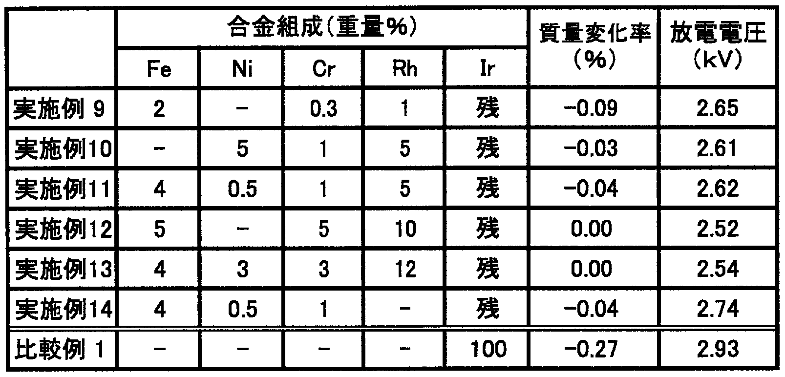
[0040] 表 2からわかるように、本実施形態で製造した Rhを含有する実施例 9〜; 13の Ir合金 からなる実施例の貴金属チップは、比較例 1よりも質量損失が少なぐ高温の酸化雰 囲気中での耐消耗性に優れていることが確認された。また、放電電圧も低いものであ つた。一方、 Rhを含有しない実施例 14では、質量変化率は少ないものの、放電電圧 が多少上昇することが分かった。 [0040] As can be seen from Table 2, the noble metal tips of Examples 9 to 13 containing Rh produced in the present embodiment were made at a higher temperature with less mass loss than Comparative Example 1. It was confirmed that it has excellent wear resistance in an oxidizing atmosphere. Also, the discharge voltage was low. On the other hand, in Example 14 containing no Rh, it was found that the discharge voltage slightly increased although the mass change rate was small.
産業上の利用可能性 Industrial applicability
[0041] 以上説明したように、本発明に係る Ir合金は、合金中の Crの作用により、基材の保 護効果に優れた酸化物皮膜を形成することができ、特に、耐酸化消耗性に優れてい る。また、 Cr濃度を適正な範囲にすることで、耐火花消耗性等の他の耐久性に関し ても従来の材料と同等以上に確保されている。従って、本発明に係る Ir合金からなる 貴金属チップを中心電極に備えることで、スパークプラグの長寿命化を図ることがで きる。 [0041] As described above, the Ir alloy according to the present invention can form an oxide film excellent in the protective effect of the base material by the action of Cr in the alloy, and in particular, the resistance to oxidation and consumption. Excellent. In addition, by making the Cr concentration within an appropriate range, other durability such as spark wear resistance is ensured to be equal to or higher than that of conventional materials. Therefore, by providing the center electrode with the noble metal tip made of the Ir alloy according to the present invention, the life of the spark plug can be extended.
Claims
Priority Applications (3)
| Application Number | Priority Date | Filing Date | Title |
|---|---|---|---|
| EP07791214A EP2045342B1 (en) | 2006-07-25 | 2007-07-24 | Noble metal alloy for spark plug and method for producing and processing the same |
| US12/064,665 US8029628B2 (en) | 2006-07-25 | 2007-07-24 | Noble metal alloy for spark plug and method for producing and processing the same |
| JP2008526770A JP4430119B2 (en) | 2006-07-25 | 2007-07-24 | Noble metal alloy for spark plug and manufacturing method thereof |
Applications Claiming Priority (4)
| Application Number | Priority Date | Filing Date | Title |
|---|---|---|---|
| JP2006-202471 | 2006-07-25 | ||
| JP2006202471 | 2006-07-25 | ||
| JP2007097465 | 2007-04-03 | ||
| JP2007-097465 | 2007-04-03 |
Publications (1)
| Publication Number | Publication Date |
|---|---|
| WO2008013159A1 true WO2008013159A1 (en) | 2008-01-31 |
Family
ID=38981470
Family Applications (1)
| Application Number | Title | Priority Date | Filing Date |
|---|---|---|---|
| PCT/JP2007/064482 Ceased WO2008013159A1 (en) | 2006-07-25 | 2007-07-24 | Noble metal alloy for spark plug and method for producing and processing the same |
Country Status (4)
| Country | Link |
|---|---|
| US (1) | US8029628B2 (en) |
| EP (1) | EP2045342B1 (en) |
| JP (1) | JP4430119B2 (en) |
| WO (1) | WO2008013159A1 (en) |
Cited By (4)
| Publication number | Priority date | Publication date | Assignee | Title |
|---|---|---|---|---|
| WO2013069822A1 (en) * | 2012-02-03 | 2013-05-16 | 住友電気工業株式会社 | Electrode material, electrode for spark plug, and spark plug |
| WO2018117135A1 (en) * | 2016-12-22 | 2018-06-28 | 石福金属興業株式会社 | Heat-resistant ir alloy |
| JP2018104816A (en) * | 2016-12-22 | 2018-07-05 | 石福金属興業株式会社 | Heat resistant Ir alloy |
| US11773473B2 (en) | 2016-12-22 | 2023-10-03 | Ishifuku Metal Industry Co., Ltd. | Heat-resistant IR alloy |
Families Citing this family (9)
| Publication number | Priority date | Publication date | Assignee | Title |
|---|---|---|---|---|
| TWI289708B (en) | 2002-12-25 | 2007-11-11 | Qualcomm Mems Technologies Inc | Optical interference type color display |
| US7342705B2 (en) | 2004-02-03 | 2008-03-11 | Idc, Llc | Spatial light modulator with integrated optical compensation structure |
| US7911428B2 (en) | 2004-09-27 | 2011-03-22 | Qualcomm Mems Technologies, Inc. | Method and device for manipulating color in a display |
| US7898521B2 (en) * | 2004-09-27 | 2011-03-01 | Qualcomm Mems Technologies, Inc. | Device and method for wavelength filtering |
| US8872085B2 (en) | 2006-10-06 | 2014-10-28 | Qualcomm Mems Technologies, Inc. | Display device having front illuminator with turning features |
| CN101600901A (en) | 2006-10-06 | 2009-12-09 | 高通Mems科技公司 | Optical loss structure integrated in illumination device of display |
| WO2009052324A2 (en) | 2007-10-19 | 2009-04-23 | Qualcomm Mems Technologies, Inc. | Display with integrated photovoltaic device |
| US8068710B2 (en) | 2007-12-07 | 2011-11-29 | Qualcomm Mems Technologies, Inc. | Decoupled holographic film and diffuser |
| DE102009046005A1 (en) * | 2009-10-26 | 2011-04-28 | Robert Bosch Gmbh | Spark plug electrode made of improved electrode material |
Citations (6)
| Publication number | Priority date | Publication date | Assignee | Title |
|---|---|---|---|---|
| JPS5077738A (en) * | 1973-10-01 | 1975-06-25 | ||
| JPH01319284A (en) | 1988-06-17 | 1989-12-25 | Ngk Spark Plug Co Ltd | Spark plug for internal combustion engine |
| JPH0554955A (en) | 1991-08-27 | 1993-03-05 | Ngk Spark Plug Co Ltd | Spark plug |
| JP2002198158A (en) * | 2000-12-27 | 2002-07-12 | Ngk Spark Plug Co Ltd | Manufacturing method of spark plug, and the spark plug |
| WO2004105204A1 (en) * | 2003-03-25 | 2004-12-02 | Ngk Spark Plug Co., Ltd. | Spark plug |
| JP2006233270A (en) * | 2005-02-24 | 2006-09-07 | Toho Kinzoku Co Ltd | Spark plug electrode and manufacturing method thereof |
Family Cites Families (10)
| Publication number | Priority date | Publication date | Assignee | Title |
|---|---|---|---|---|
| JPS62226592A (en) * | 1986-03-28 | 1987-10-05 | 日本特殊陶業株式会社 | Ignition plug |
| DD288113A5 (en) * | 1989-07-03 | 1991-03-21 | Veb Mansfeld-Komb.,De | METHOD FOR PRODUCING A THERMALLY STABLE IRIDIUM POWDER |
| JPH07268574A (en) | 1994-03-25 | 1995-10-17 | Tanaka Kikinzoku Kogyo Kk | Iridium wire manufacturing method |
| GB2302367B (en) * | 1995-06-15 | 1998-11-25 | Nippon Denso Co | Spark plug for internal combustion engine |
| US7323811B2 (en) * | 2001-08-23 | 2008-01-29 | Federal-Mogul Ignition (U.K.) Limited | Noble metal tip for spark plug electrode and method of making same |
| JP2003317896A (en) * | 2002-02-19 | 2003-11-07 | Denso Corp | Spark plug |
| GB0216323D0 (en) * | 2002-07-13 | 2002-08-21 | Johnson Matthey Plc | Alloy |
| EP1628375B1 (en) * | 2003-05-28 | 2010-05-05 | Ngk Spark Plug Co., Ltd. | Spark plug |
| US20050168121A1 (en) * | 2004-02-03 | 2005-08-04 | Federal-Mogul Ignition (U.K.) Limited | Spark plug configuration having a metal noble tip |
| KR20090003271A (en) * | 2006-03-24 | 2009-01-09 | 페더럴-모걸 코오포레이숀 | spark plug |
-
2007
- 2007-07-24 WO PCT/JP2007/064482 patent/WO2008013159A1/en not_active Ceased
- 2007-07-24 US US12/064,665 patent/US8029628B2/en not_active Expired - Fee Related
- 2007-07-24 JP JP2008526770A patent/JP4430119B2/en not_active Expired - Fee Related
- 2007-07-24 EP EP07791214A patent/EP2045342B1/en not_active Not-in-force
Patent Citations (6)
| Publication number | Priority date | Publication date | Assignee | Title |
|---|---|---|---|---|
| JPS5077738A (en) * | 1973-10-01 | 1975-06-25 | ||
| JPH01319284A (en) | 1988-06-17 | 1989-12-25 | Ngk Spark Plug Co Ltd | Spark plug for internal combustion engine |
| JPH0554955A (en) | 1991-08-27 | 1993-03-05 | Ngk Spark Plug Co Ltd | Spark plug |
| JP2002198158A (en) * | 2000-12-27 | 2002-07-12 | Ngk Spark Plug Co Ltd | Manufacturing method of spark plug, and the spark plug |
| WO2004105204A1 (en) * | 2003-03-25 | 2004-12-02 | Ngk Spark Plug Co., Ltd. | Spark plug |
| JP2006233270A (en) * | 2005-02-24 | 2006-09-07 | Toho Kinzoku Co Ltd | Spark plug electrode and manufacturing method thereof |
Non-Patent Citations (1)
| Title |
|---|
| See also references of EP2045342A4 |
Cited By (7)
| Publication number | Priority date | Publication date | Assignee | Title |
|---|---|---|---|---|
| WO2013069822A1 (en) * | 2012-02-03 | 2013-05-16 | 住友電気工業株式会社 | Electrode material, electrode for spark plug, and spark plug |
| JP2014029002A (en) * | 2012-02-03 | 2014-02-13 | Sumitomo Electric Ind Ltd | Electrode material and electrode for spark plug, and spark plug |
| WO2018117135A1 (en) * | 2016-12-22 | 2018-06-28 | 石福金属興業株式会社 | Heat-resistant ir alloy |
| JP2018104816A (en) * | 2016-12-22 | 2018-07-05 | 石福金属興業株式会社 | Heat resistant Ir alloy |
| US11131008B2 (en) | 2016-12-22 | 2021-09-28 | Ishifuku Metal Industry Co., Ltd. | Heat-resistant Ir alloy |
| JP7057935B2 (en) | 2016-12-22 | 2022-04-21 | 石福金属興業株式会社 | Heat resistant Ir alloy |
| US11773473B2 (en) | 2016-12-22 | 2023-10-03 | Ishifuku Metal Industry Co., Ltd. | Heat-resistant IR alloy |
Also Published As
| Publication number | Publication date |
|---|---|
| EP2045342B1 (en) | 2012-09-05 |
| EP2045342A1 (en) | 2009-04-08 |
| US20090293995A1 (en) | 2009-12-03 |
| US8029628B2 (en) | 2011-10-04 |
| JPWO2008013159A1 (en) | 2009-12-17 |
| EP2045342A4 (en) | 2010-09-01 |
| JP4430119B2 (en) | 2010-03-10 |
Similar Documents
| Publication | Publication Date | Title |
|---|---|---|
| WO2008013159A1 (en) | Noble metal alloy for spark plug and method for producing and processing the same | |
| JP3731600B2 (en) | Copper alloy and manufacturing method thereof | |
| JP5232917B2 (en) | Spark plug | |
| JP7057935B2 (en) | Heat resistant Ir alloy | |
| WO2016186070A1 (en) | Copper alloy sputtering target and method for manufacturing same | |
| JP5650969B2 (en) | Electrode material, spark plug electrode, and spark plug | |
| JP2006274383A (en) | Copper material manufacturing method and copper material | |
| JP5273725B2 (en) | Plug electrode material for internal combustion engines | |
| CN103282523B (en) | Metal wire rod made of iridium-ontaining alloy | |
| JP6155575B2 (en) | Electrode material, spark plug electrode, and spark plug | |
| WO2018117135A1 (en) | Heat-resistant ir alloy | |
| JP7531194B2 (en) | Heat-resistant Ir alloy wire | |
| JP5590979B2 (en) | Spark plug electrode material with excellent spark wear resistance | |
| KR100537693B1 (en) | Fe- base heat-resistant alloy having improved the high temperature oxidation resistance and the method of making the same | |
| WO2011102355A1 (en) | Spark plug electrode material having excellent spark consumption resistance and excellent discharge characteristics | |
| JP6075707B2 (en) | Electrode material, spark plug electrode, and spark plug | |
| JP2004291052A (en) | Casting method for low phosphorous deoxidized copper, low phosphorous deoxidized copper ingot produced by the method, and low phosphorous deoxidized copper material | |
| JP2019218572A (en) | HEAT-RESISTANT Ir ALLOY | |
| JP5912986B2 (en) | Electrode material, electrode for spark plug and spark plug | |
| JPH11209835A (en) | High-strength, high-conductivity chromium-zircon copper alloy with excellent fusion resistance | |
| JP2007167880A (en) | Brazing filler metal and its production method |
Legal Events
| Date | Code | Title | Description |
|---|---|---|---|
| WWE | Wipo information: entry into national phase |
Ref document number: 2007791214 Country of ref document: EP |
|
| WWE | Wipo information: entry into national phase |
Ref document number: 2008526770 Country of ref document: JP |
|
| 121 | Ep: the epo has been informed by wipo that ep was designated in this application |
Ref document number: 07791214 Country of ref document: EP Kind code of ref document: A1 |
|
| NENP | Non-entry into the national phase |
Ref country code: DE |
|
| NENP | Non-entry into the national phase |
Ref country code: RU |
|
| WWE | Wipo information: entry into national phase |
Ref document number: 12064665 Country of ref document: US |