WO2007117311A2 - A dsl modem and a method of providing operating power for same - Google Patents
A dsl modem and a method of providing operating power for same Download PDFInfo
- Publication number
- WO2007117311A2 WO2007117311A2 PCT/US2006/061319 US2006061319W WO2007117311A2 WO 2007117311 A2 WO2007117311 A2 WO 2007117311A2 US 2006061319 W US2006061319 W US 2006061319W WO 2007117311 A2 WO2007117311 A2 WO 2007117311A2
- Authority
- WO
- WIPO (PCT)
- Prior art keywords
- frequency
- transmission medium
- component
- carrier wave
- power
- Prior art date
- Legal status (The legal status is an assumption and is not a legal conclusion. Google has not performed a legal analysis and makes no representation as to the accuracy of the status listed.)
- Ceased
Links
Classifications
-
- H—ELECTRICITY
- H04—ELECTRIC COMMUNICATION TECHNIQUE
- H04M—TELEPHONIC COMMUNICATION
- H04M19/00—Current supply arrangements for telephone systems
- H04M19/08—Current supply arrangements for telephone systems with current supply sources at the substations
-
- H—ELECTRICITY
- H04—ELECTRIC COMMUNICATION TECHNIQUE
- H04B—TRANSMISSION
- H04B2203/00—Indexing scheme relating to line transmission systems
- H04B2203/54—Aspects of powerline communications not already covered by H04B3/54 and its subgroups
- H04B2203/5462—Systems for power line communications
- H04B2203/547—Systems for power line communications via DC power distribution
Definitions
- a multiple dwelling unit is a structure, such as a hotel, apartment building, dormitory, or hospital, that provides individual accommodations and associated services to a number of occupants.
- the occupants may be relatively long term, as in an apartment building or dormitory, or short term, as in a hotel.
- An operator of an MDU must provide access to certain essential services to the MDU' s occupants, such as electricity, water, telephone, etc.
- Different types of MDUs will use different technology to provide internal telephone service.
- An apartment building may provide a direct connection, typically via an unshielded twisted pair (UTP) of copper wires, from the local public switched telephone network (PSTN) to each unit, whereas a hotel may provide a connection, also via a UTP, from each unit to a private branch exchange (PBX).
- UTP unshielded twisted pair
- PBX private branch exchange
- each telephone extension within the MDU connects to a central piece of PBX equipment and the PBX connects calls between the extensions, such as between a hotel room and the front desk.
- a number of trunk lines connect from the PBX to the local PSTN for making and receiving calls external to the MDU.
- the local PSTN or the PBX in conjunction with the local PSTN, provides analog voice communication and DC operating power for basic telephone services (POTS - Plain Old Telephone Service) over a UTP to each unit of an MDU.
- POTS Plain Old Telephone Service
- the upper limit of the UTP' s usable bandwidth can be upwards of 10 MHz, while POTS only utilizes the 0 - 4 kHz frequency band.
- HSIA high-speed internet access
- the MDU as a whole may connect to the internet through an xDSL circuit connected to a local loop data circuit via a dedicated transmission line, such as a Tl line.
- a dedicated transmission line such as a Tl line.
- multiple units may access the internet by connecting to the xDSL circuit, for instance embodied within a DSL access multiplexer (DSLAM).
- the DSLAM is connected to the MDU's internal phone lines between the PBX equipment and the units of the MDU.
- the DSLAM receives a high-bandwidth digital data signal from the local loop data circuit, demultiplexes the data signal according to the desired destination of the data (creating multiple lower bandwidth digital data signals), and modulates the digital data signals with a high-frequency analog waveform.
- an xDSL modem uses high -pass filter circuitry to isolate the high- frequency modulated data signals being transmitted over the phone line while any phone jacks not connected to the xDSL modem will use passive low-pass filter circuitry to isolate the lower frequency POTS signals, such as voice communication and dial tone signals and the DC operating power.
- the above process is reversed for outgoing network traffic.
- an xDSL modem receives DC operating power from a transformer/rectifier that converts AC power received from a 110-120 V 60 Hz wall outlet to low voltage DC power.
- One possible deterrent to theft of the xDSL modem is to physically secure the xDSL modem to the MDU itself, for instance to a wall of the unit or to a large piece of furniture.
- the secured xDSL modem will still need be connected to the unit's phone line and to a power source and these connections may still inadvertently become unplugged causing an unnecessary service outage. If the connection between the phone line and the xDSL modem were inaccessible to occupants of the unit, the problem of disconnection of the phone line would be avoided.
- an xDSL modem having means for connecting to an MDU unit's telephone line and means for providing operating power to the xDSL modem that are inaccessible to an occupant of the unit. It is also desirable that the design of the xDSL modem discourage theft. Further, it is also desirable that installation of the xDSL modem and any related components be simple and not require any replacement, removal or complex reconfiguration of existing telephone wiring.
- an xDSL modem apparatus comprising a port for transmitting and receiving carrier waves, a low-pass filtering means for isolating a low-frequency component of a received composite carrier wave below a first frequency and transmitting the isolated low- frequency component of the composite carrier wave, a high-pass filtering means for isolating a high-frequency component of the composite carrier wave above a second frequency, a band-pass filtering means for isolating a power component of the composite carrier wave, the power component being in a frequency range between the first and second frequencies, an xDSL modem for demodulating the high-frequency component of the composite carrier wave and recovering a computer readable bitstream therefrom and transmitting the computer readable bitstream, and for modulating a high-frequency carrier wave with a received computer readable bitstream and transmitting the modulated carrier wave, and a means for utilizing the power component of the composite carrier wave to provide operating power for the DSL modem.
- cable interface device for combining an alternating current power carrier, a first carrier component in a first frequency band and a second carrier component in a second frequency band into a composite carrier wave and injecting the composite carrier wave onto a first transmission medium having a resonant frequency between said first and second frequency bands, the first component being audio and the second component being data
- the interface device comprising a first input for connection to a second transmission medium, the second transmission medium being for delivering the first component to the first transmission medium, a second input for connection to a third transmission medium, the third transmission medium being for delivering the second component to the first transmission medium, an output for connection to the first transmission medium for transmitting the composite carrier wave, a power carrier generator connected to the output, and a feedback path between the power carrier generator and the first transmission medium, wherein, in operation, the power carrier generator generates an AC power carrier wave oscillating at the resonant frequency of the first transmission medium and delivers the AC power carrier wave to the first transmission medium.
- a method of providing electrical power to a primary device the primary device being electrically connected to a remote device via a transmission medium, the transmission medium having a first section terminating at the remote device and a second section terminating at the primary device, and the method comprising (a) determining a resonant frequency of the second section of the transmission medium, (b) generating an oscillating electrical power carrier at the resonant frequency of the second section, (c) injecting the power carrier into the transmission medium at a point of intersection between the first and second sections, and (d) receiving the power carrier at the primary device.
- a method of installing an xDSL modem on to a phone jack wall plate the xDSL modem being housed in an external casing, the xDSL modem having a telephone line connection means accessible from a rear side of the casing, the phone jack wall plate having an unpopulated phone jack and being secured to a structure by a screw having a threaded portion and a head
- the method comprising loosening the screw securing the wall plate to the structure, positioning an adapter plate over the wall plate, the adapter plate having a frame surrounding a recess and a rearward wall, the rearward wall having a primary opening and at least one keyhole opening, the at least one keyhole opening having a lower section and a upper section, the lower section being larger than the upper section, wherein the adapter plate is positioned over the wall plate such that the rearward wall is in contact with the wall plate, the head of the screw passes through the lower section of the at least one
- FIG. 1 shows a block diagram of a power injection circuit embodying an aspect of the present invention
- FIG. 2 shows a block diagram of a DSLAM containing multiple power injection circuits embodying an aspect of the present invention
- FIG. 3 shows a block diagram of a phone jack wall plate xDSL modem attachment embodying an aspect of the present invention
- FIG. 4 shows a partial block diagram of a multiple dwelling unit in which an embodiment of the present invention is installed
- FIG. 5 shows an enlarged schematic view of a telephone line junction box embedded in a wall
- FIG. 6 shows an enlarged schematic view of a conventional telephone jack wall plate
- FIG. 7 shows an enlarged schematic view of an adapter plate used in an installation process embodying an aspect of the present invention.
- FIG. 8 shows a side schematic view of the conventional telephone jack wall plate, the adapter plate, and an xDSL modem attachment embodying an aspect of the present invention.
- the following description relates to two components, each embodying aspects of the present invention and intended to be installed at separate locations within an MDU.
- the first component a cable interface device
- the second component a telephone jack wall plate attachment
- the upstream is intended to refer to any portion of a transmission medium, component, or sub-component oriented away from the individual unit of the MDU
- the term downstream is intended to refer to any portion of a transmission medium, component, or sub-component oriented towards the individual unit of the MDU. No limitation on the direction of signal propagation is intended with the use of the terms upstream and downstream.
- FIG. 1 shows the internal functional blocks of a cable interface device (CID) 2 embodying an aspect of the present invention.
- An upstream analog phone line 6 is connected to an upstream side 10 of a low-pass filter circuit 14 having a cutoff frequency f lp>1 .
- a downstream side 18 of the low-pass filter circuit 14 is connected to an intermediate transmission medium 20, such as a UTP, at a common node 22.
- An upstream xDSL service line 26 is connected to an upstream side 34 of a high-pass filter circuit 38 having a cutoff frequency f hP;1 .
- a downstream side 42 of the high-pass filter circuit 38 is connected to the intermediate transmission medium 20 at the common node 22.
- a DC power supply 46 provides electrical power to an input side 50 of an adaptive frequency power generator (AFPG) 54.
- the DC power supply 46 contains a transformer/rectifier circuit (not shown) supplied by an AC power supply 58, such as a conventional 110-220 V 60 Hz wall outlet.
- the AFPG 54 converts the electrical power received from the DC power supply 46 to an AC power carrier with a frequency of fo and transmits the AC power carrier from an output side 62 of the AFPG 54.
- the output side of the AFPG 62 is connected to an input side 66 of a bandpass filter 70 having a lower cutoff frequency f lc>1 and an upper cutoff frequency f uc>1 .
- An output side 74 of the band-pass filter is connected to the intermediate transmission 20 medium at the common node 22.
- the AFPG 54 is also connected to the intermediate transmission medium 20 through a feedback path 78.
- the band-pass filter's cutoff frequencies are selected to allow a range of frequencies, corresponding to expected values of fo, to propagate through the filter but to block frequency values that would be allowed to pass by either the low-pass filter 14 or the high-pass filter 38.
- the low-pass filter 14 and the high-pass filter 38 act to isolate components of a waveform received from the intermediate transmission medium 20 based on the frequency of the components.
- the low-pass filter 14 will pass frequency components less than f lp>1 to the upstream analog phone line 6 and will block higher frequency components.
- the high-pass filter 34 will pass frequency components greater than f hP;1 to the xDSL service line and will block lower frequency components.
- the band-pass filter 70 acts to block frequency components outside the frequency band between fbp,ic,i an d fbp,uc,i, i-e. the components allowed to pass by the low-pass and high pass filters.
- the band-pass filter's cutoff frequencies are selected to allow a range of frequencies, corresponding to expected values of f 0 , to propagate from the AFPG 54, through the band-pass filter and on to the intermediate transmission medium 20 but to block the AFPG from receiving low and high frequency signals from the intermediate transmission medium 20.
- a transmission medium such as a UTP has certain inherent physical characteristics that present an impedance to an AC carrier wave, primarily capacitance and inductance.
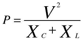
- the power loss due to the capacitive and inductive characteristics of the transmission medium can be calculated by the equation:
- V the peak voltage of carrier signal
- X c the capacitive reactance of the transmission medium
- X L the inductive reactance of the transmission medium
- P the power loss.
- the values of the capacitive and inductive reactance are both a function of the physical properties of the transmission medium and the frequency of the AC carrier wave.
- the capacitive reactance is inversely proportional to frequency, and thus as the frequency of the carrier increases, the capacitive reactance will decrease and the associated power losses will increase.
- the inductive reactance is directly proportional to the frequency of the AC carrier, and thus as the frequency of a carrier decreases, the inductive reactance also decreases and the associated power losses will increase.
- the reactive power loss in an AC carrier on a transmission medium is minimized when the capacitive reactance equals the inductive reactance.
- the frequency at which this occurs is known as the transmission medium's resonant frequency f r .
- the intermediate transmission medium's resonant frequency will vary depending on the physical characteristics of the medium, such as wire gauge, twists per inch, shielding and length.
- the frequency fo of the AC power carrier generated by the AFPG 54 should be as close to the intermediate transmission medium's resonant frequency f r as possible.
- the AFPG 54 includes an oscillator that receives feedback from its load.
- the feedback causes the oscillator's operating frequency to be a function of the capacitive and inductive components of the oscillator's load, and will, after a brief period upon power up, stabilize at the load's resonant frequency f r . Therefore, the AC power carrier's frequency fo will equal the resonant frequency of the intermediate transmission medium, which in turn will depend on cable configuration (length, cable type, bridge taps, etc.), and the reactive power loss of the AC power carrier will be minimized.
- the oscillator is a Royer oscillator.
- Royer oscillators are commonly used in flat panel display technology and are well understood by those skilled in the art (see U.S. Patent No. 6,633,138 and Jim Williams, "A Fourth Generation of LCD Backlight Technology” Linear Technology, Application Note #65, pages 32 - 36 and 119).
- the AFPG 54 will be electrically connected to a power conversion block (114, FIG. 2) containing a transformer that presents an inductive load to the AFPG 54.
- the corresponding capacitive load largely depends on the length of the intermediate transmission medium. If the length of the intermediate transmission medium 20 is less than some minimum amount (e.g. 50 feet), its capacitive load, even combined with any capacitive load of the band-pass filter 70, may result in a resonant frequency f r that falls outside of the frequency band of the band-pass filter 70. Therefore, it may be desirable to include a bias capacitor circuit (not shown) at the downstream side 62 of the AFPG 54 to balance the inductive load of the power conversion block.
- multiple CIDs are incorporated into a DSLAM 79.
- An upstream analog phone line 6 is routed to each CID 2 within the DSLAM 79 from a source (not shown), such as a PBX.
- An xDSL service line 26, such as a Tl line is routed to the DSLAM from a local loop data circuit (not shown) and is connected to an xDSL circuit 80.
- the xDSL circuit 80 connects to each CID 2.
- Each CID 2 connects to an inte ⁇ nediate transmission medium 20, which is connected in turn to a phone jack (not shown) of an individual unit of the MDU.
- FIG. 3 shows the internal functional blocks of a telephone jack wall plate attachment 82 embodying an aspect of the present invention.
- the telephone jack wall plate attachment 82 includes a low-pass filter 86 having a cutoff frequency f lp>2 , a band-pass filter 90 having a lower cutoff frequency f lc>2 (where f lc>2 > f lp>2 ) and an upper cutoff frequency f uc>2 , and a high-pass filter 94 having a cutoff frequency f hPj2 (where fh Pj2 > f uc ,2)-
- the intermediate transmission medium 20 is connected to all three filter circuits at a common node 98.
- the low-pass filter 86 is connected to a downstream analog voice signal I/O 102 (such as a conventional telephone jack).
- the high-pass filter 94 is connected to a customer premises equipment (CPE) xDSL modem 106.
- the CPE xDSL modem 106 is connected to a downstream digital data VO 110 (such as a conventional Ethernet jack).
- the band-pass filter 90 is connected to a power conversion block 114.
- the power conversion block 114 may include a transformer and a rectifier (not shown).
- the three filters 86, 90, 94 act to isolate components of a composite carrier wave received from the intermediate transmission medium 20.
- the low-pass filter 86 will pass frequency components less than f lp>2 to the downstream analog voice signal VO 102 and will block higher frequency components.
- the band-pass filter 94 will pass frequency components in the frequency band between fb P ,ic,2 and fb p , uc ,2 to the power conversion block 114 and will block components outside this frequency band.
- the high-pass filter 94 will pass frequency components greater than f hP;2 to the xDSL CPE modem 106 and will block lower frequency components.
- the CID 2 receives a low-frequency analog carrier wave from the upstream analog phone line 6 and a high-frequency analog carrier wave, modulated with digital data, from the upstream xDSL service line 26.
- the low-frequency carrier wave and the high-frequency carrier wave propagate through the low-pass filter 14 and the high-pass filter 38 respectively and then on to the intermediate transmission medium 20.
- the CID 2 injects the AC power carrier generated by the AFPG 54 onto the intermediate transmission medium.
- the three carriers combine to form a composite carrier waveform carrying analog voice data, A/C power and modulated digital data.
- Each component of the composite carrier wave operates in its own, non- overlapping, frequency range.
- the three filter circuits isolate the components of the composite carrier.
- the low-pass filter blocks 86 all the components of the composite carrier except the low-frequency voice signal component.
- the low-frequency voice signal component passes through the low-pass filter 86 to the phone jack 102.
- the band-pass filter 90 blocks all the components of the composite carrier except the AC power carrier originally injected by the CID 2 which passes through the band-pass filter 90 to the power conversion block 114.
- the power conversion block 114 converts the AC power carrier to DC operating power usable by the xDSL CPE modem 106.
- the high-pass filter 94 blocks all the components of the composite carrier except the high-frequency modulated digital data component which passes through the high-pass filter 94 to the xDSL CPE modem 106.
- the xDSL CPE modem 106 uses the DC operating power received from the power conversion block 114 to translate the high-frequency modulated digital data component into a packetized digital signal in a way determined by the standard of the particular version of DSL technology being implemented by the xDSL CPE modem 106.
- the ability of the CID 2 to self-tune to the AC power carrier to the resonant frequency of the intermediate transmission medium 20 allows for greater flexibility in installation as the AFPG 54 does not have to be configured based on the physical characteristics of the individual intermediate transmission medium (wire gauge, twists per inch, shielding, length, etc).
- a CID 2 must be installed at a convenient location in the MDU, for instance near a junction box, and a wall plate attachment 82 must be installed in the desired unit(s).
- the CID 2 is installed at an access point 120, such as a utility closet or service room, in an MDU.
- the phone line and xDSL service line are divided into upstream sections 6, 26 from the access point to upstream equipment (not shown), such as an xDSL circuit in the case of the xDSL service line or a central PBX device in the case of the analog phone line, and an intermediate section 20 from the phone line access point to a desired telephone jack 124 in a unit 128 of the MDU.
- the upstream section of the phone line 6 is connected to the upstream side (10, FIG. 1) of the low-pass filter (14, FIG. 1) of the CID 2 and the intermediate section 20 is connected to the common node (22, FIG. 1) of the three CID filters.
- the telephone jack wall plate attachment 82 is attached to the desired phone jack 124 whereby the intermediate section 20 is also connected to the common node (98, FIG. 3) of the three wall plate attachment filters.
- a DSLAM 79 containing multiple CIDs may be installed in a utility room of the MDU containing a system block 136 and a station block 137.
- Telephone lines 138 from a source (not shown), such as a PBX are terminated at the system block 136 and the telephone lines 139 from the units of the MDU (not shown) are terminated at the station block 137.
- the system block 136 and the station block 137 are connected together by jumper wires (not shown).
- an installer disconnects the jumper wires and installs a new termination block 140 between the system and station blocks.
- the installer installs jumpers 141 from the system block 136 to a system side 142 of the new termination block 140, from the system side 142 to the DSLAM 79, from the DSLAM 79 to a station side 143 of the new termination block, and from the station side 143 to the station block 138.
- a conventional 110/240 VAC power outlet may provide operating power to the DSLAM 79.
- the waveform entering the DSLAM from the PBX to a unit of the MDU contains only the low-frequency POTS signal for the unit.
- the waveform is a composite carrier containing the low- frequency POTS signal, a high-frequency modulated digital data signal, and a power carrier.
- a wall plate attachment 82 embodying the present invention may be quickly installed on an existing telephone jack wall plate 160 in a unit of an MDU.
- the wall plate attachment 82 is housed in a casing 192.
- the casing includes an RJIl phone jack 196, connected internally to the downstream analog voice data I/O (102, FIG. 1) and a Tl Ethernet jack 200, connected internally to the downstream digital data I/O (110, FIG. 3).
- the wall plate attachment casing also includes a DC power input 204.
- the DC power input 204 enables the option of providing operating power to the wall plate attachment's DSL modem in the event no CID is installed upstream of the telephone jack wall plate.
- the frame 176 of the adapter plate 172 and the casing 192 are formed to engage with a snap fit.
- the telephone jack wall plate 160 is attached by screws 164 to an outlet box (not shown) that is mounted behind the wall of the unit.
- An RJl 1 jack 168 that is connected to the telephone line is mounted in the wall plate 160.
- the adapter plate 172 comprises a rectangular frame 176 and a rear wall 180.
- the rear wall 180 is formed with two keyhole openings 184 and with a larger or primary opening 188.
- the installer should position the adapter plate 172 such that the telephone jack 168 is accessible through the adapter plate's primary opening 188 and such that the screw heads pass through the wider portion of the two keyhole openings 184.
- the installer slides the adapter plate 172 downwards until it is supported by the screws 164. Next, the installer should tighten the screws, thereby securing the adapter plate 172 to the wall plate 160.
- the present invention therefore provides an xDSL modem having means for connecting to an MDU unit's telephone line and means for providing operating power to the xDSL modem, both of which are inaccessible to an occupant of the unit.
- the xDSL modem is designed to receive operating power over the phone line, the xDSL modem is essentially useless outside of the MDU and there is therefore little point in stealing it. Further, installation of the xDSL modem is simple and does not require any replacement, removal or complex reconfiguration of existing telephone wiring.
Landscapes
- Engineering & Computer Science (AREA)
- Signal Processing (AREA)
- Telephonic Communication Services (AREA)
- Digital Transmission Methods That Use Modulated Carrier Waves (AREA)
Abstract
Description
Claims
Priority Applications (1)
| Application Number | Priority Date | Filing Date | Title |
|---|---|---|---|
| DE112006003291T DE112006003291B4 (en) | 2005-11-30 | 2006-11-29 | A DSL modem and a method for providing operating power therefor |
Applications Claiming Priority (2)
| Application Number | Priority Date | Filing Date | Title |
|---|---|---|---|
| US11/291,333 US7512220B2 (en) | 2005-11-30 | 2005-11-30 | DSL modem and a method of providing operating power for same |
| US11/291,333 | 2005-11-30 |
Publications (2)
| Publication Number | Publication Date |
|---|---|
| WO2007117311A2 true WO2007117311A2 (en) | 2007-10-18 |
| WO2007117311A3 WO2007117311A3 (en) | 2008-11-20 |
Family
ID=38087557
Family Applications (1)
| Application Number | Title | Priority Date | Filing Date |
|---|---|---|---|
| PCT/US2006/061319 Ceased WO2007117311A2 (en) | 2005-11-30 | 2006-11-29 | A dsl modem and a method of providing operating power for same |
Country Status (3)
| Country | Link |
|---|---|
| US (1) | US7512220B2 (en) |
| DE (1) | DE112006003291B4 (en) |
| WO (1) | WO2007117311A2 (en) |
Families Citing this family (5)
| Publication number | Priority date | Publication date | Assignee | Title |
|---|---|---|---|---|
| US8437468B2 (en) * | 2009-10-09 | 2013-05-07 | At&T Intellectual Property I, L. P. | Methods, systems and products for providing modem functions |
| FR2961989B1 (en) * | 2010-06-23 | 2012-08-17 | Freebox | EQUIPMENT / BLOCK ASSEMBLY WITH DATA TRANSMISSION BY CURRENT CARRIERS ONLINE CPL |
| US20160211673A1 (en) * | 2015-01-16 | 2016-07-21 | Hamilton Sundstrand Corporation | Localized source selection and power conversion power distribution system |
| US10063316B2 (en) * | 2016-04-30 | 2018-08-28 | Nanoprecision Products, Inc. | Wall plate having a built-in modem for performing electrical-to-optical conversion, optical-to-electrical conversion and protocol-to-protocol conversion |
| US10129889B1 (en) * | 2015-09-01 | 2018-11-13 | Sprint Spectrum L.P. | Selecting primary and secondary component carriers for carrier aggregation based on carrier receive power at a UE, transmit power, frequency, and other carrier attributes |
Family Cites Families (5)
| Publication number | Priority date | Publication date | Assignee | Title |
|---|---|---|---|---|
| US6114814A (en) | 1998-12-11 | 2000-09-05 | Monolithic Power Systems, Inc. | Apparatus for controlling a discharge lamp in a backlighted display |
| US6690677B1 (en) * | 1999-07-20 | 2004-02-10 | Serconet Ltd. | Network for telephony and data communication |
| US6549616B1 (en) * | 2000-03-20 | 2003-04-15 | Serconet Ltd. | Telephone outlet for implementing a local area network over telephone lines and a local area network using such outlets |
| WO2001082584A2 (en) * | 2000-04-24 | 2001-11-01 | Broadcom Corporation | System and method for providing power over a home phone line network |
| US6904149B2 (en) * | 2000-08-11 | 2005-06-07 | Corning Cable Systems Llc | Tool-less wall-mount distributed filter housing |
-
2005
- 2005-11-30 US US11/291,333 patent/US7512220B2/en not_active Expired - Fee Related
-
2006
- 2006-11-29 DE DE112006003291T patent/DE112006003291B4/en not_active Expired - Fee Related
- 2006-11-29 WO PCT/US2006/061319 patent/WO2007117311A2/en not_active Ceased
Also Published As
| Publication number | Publication date |
|---|---|
| WO2007117311A3 (en) | 2008-11-20 |
| DE112006003291B4 (en) | 2011-07-21 |
| US20070121924A1 (en) | 2007-05-31 |
| DE112006003291T5 (en) | 2008-10-23 |
| US7512220B2 (en) | 2009-03-31 |
Similar Documents
| Publication | Publication Date | Title |
|---|---|---|
| JP4515918B2 (en) | Method and system for providing DC power over a local telephone line | |
| CA2603867C (en) | Network interface device with a remote power source | |
| EP1302023B1 (en) | System and method for providing power over a home phone line network | |
| US5974139A (en) | Line isolation device for asymmetrical digital subscriber line | |
| EP1142291B1 (en) | Network data filtering | |
| US6239672B1 (en) | Wall mount filter for a digital subscriber line (xDSL) network and methods of installation and manufacture | |
| US6674843B1 (en) | Apparatus system and method for enabling multi-frequency communication over a telephone network having a billing/tax tone | |
| WO2007123650A1 (en) | Method and apparatus for providing power to a network interface device via telephone lines | |
| US20010008534A1 (en) | Digital subscriber line multiplexer | |
| US7512220B2 (en) | DSL modem and a method of providing operating power for same | |
| US6850618B1 (en) | Central office interface techniques for digital subscriber lines | |
| US6826278B2 (en) | Central office interface techniques for digital subscriber lines | |
| US6839343B2 (en) | Physical layer router system and method | |
| US6449362B1 (en) | Apparatus, systems and methods for isolating ADSL signals from POTS signals | |
| EP1009156A2 (en) | Device and method for local power and signal feeding into subscriber lines | |
| US6829336B1 (en) | System and method for active filtering in a telecommunications network | |
| CA2692156A1 (en) | Apparatus, method and system for providing new communication services over existing wiring | |
| EP1284088B1 (en) | Termination device for a telephone line | |
| US20030138082A1 (en) | Line interface for combining a voice band signal and an XDSL signal on a twisted-pair copper line | |
| KR100543927B1 (en) | Telephone line terminal | |
| AU2003200045B2 (en) | Asymmetric Digital Subscriber Line (ADSL) Filter | |
| CN100576764C (en) | Apparatus for distributing digital signals | |
| GB2339506A (en) | Line balancing interface to support simultaneous voice band and broadband data transmissions over in-house telephony wiring |
Legal Events
| Date | Code | Title | Description |
|---|---|---|---|
| 121 | Ep: the epo has been informed by wipo that ep was designated in this application |
Ref document number: 06850832 Country of ref document: EP Kind code of ref document: A2 |
|
| RET | De translation (de og part 6b) |
Ref document number: 112006003291 Country of ref document: DE Date of ref document: 20081023 Kind code of ref document: P |
|
| WWE | Wipo information: entry into national phase |
Ref document number: 112006003291 Country of ref document: DE |
|
| 122 | Ep: pct application non-entry in european phase |
Ref document number: 06850832 Country of ref document: EP Kind code of ref document: A2 |
|
| REG | Reference to national code |
Ref country code: DE Ref legal event code: 8607 |