WO2007063922A1 - Communication terminal and communication system, and display method of communication terminal - Google Patents
Communication terminal and communication system, and display method of communication terminal Download PDFInfo
- Publication number
- WO2007063922A1 WO2007063922A1 PCT/JP2006/323857 JP2006323857W WO2007063922A1 WO 2007063922 A1 WO2007063922 A1 WO 2007063922A1 JP 2006323857 W JP2006323857 W JP 2006323857W WO 2007063922 A1 WO2007063922 A1 WO 2007063922A1
- Authority
- WO
- WIPO (PCT)
- Prior art keywords
- display
- screen
- image
- unit
- area
- Prior art date
- Legal status (The legal status is an assumption and is not a legal conclusion. Google has not performed a legal analysis and makes no representation as to the accuracy of the status listed.)
- Ceased
Links
Classifications
-
- H—ELECTRICITY
- H04—ELECTRIC COMMUNICATION TECHNIQUE
- H04N—PICTORIAL COMMUNICATION, e.g. TELEVISION
- H04N7/00—Television systems
- H04N7/14—Systems for two-way working
- H04N7/15—Conference systems
- H04N7/152—Multipoint control units therefor
-
- H—ELECTRICITY
- H04—ELECTRIC COMMUNICATION TECHNIQUE
- H04M—TELEPHONIC COMMUNICATION
- H04M1/00—Substation equipment, e.g. for use by subscribers
- H04M1/253—Telephone sets using digital voice transmission
- H04M1/2535—Telephone sets using digital voice transmission adapted for voice communication over an Internet Protocol [IP] network
-
- H—ELECTRICITY
- H04—ELECTRIC COMMUNICATION TECHNIQUE
- H04M—TELEPHONIC COMMUNICATION
- H04M1/00—Substation equipment, e.g. for use by subscribers
- H04M1/72—Mobile telephones; Cordless telephones, i.e. devices for establishing wireless links to base stations without route selection
- H04M1/724—User interfaces specially adapted for cordless or mobile telephones
- H04M1/72403—User interfaces specially adapted for cordless or mobile telephones with means for local support of applications that increase the functionality
- H04M1/72427—User interfaces specially adapted for cordless or mobile telephones with means for local support of applications that increase the functionality for supporting games or graphical animations
-
- H—ELECTRICITY
- H04—ELECTRIC COMMUNICATION TECHNIQUE
- H04N—PICTORIAL COMMUNICATION, e.g. TELEVISION
- H04N7/00—Television systems
- H04N7/14—Systems for two-way working
- H04N7/141—Systems for two-way working between two video terminals, e.g. videophone
- H04N7/147—Communication arrangements, e.g. identifying the communication as a video-communication, intermediate storage of the signals
-
- H—ELECTRICITY
- H04—ELECTRIC COMMUNICATION TECHNIQUE
- H04M—TELEPHONIC COMMUNICATION
- H04M2250/00—Details of telephonic subscriber devices
- H04M2250/62—Details of telephonic subscriber devices user interface aspects of conference calls
Definitions
- the present invention relates to a communication terminal such as a mobile phone, a communication system, and a communication terminal display method, and more particularly to a communication terminal and communication system capable of multipoint communication, and a communication terminal display method. .
- a representative example of multipoint communication is a video conference system.
- multiple terminals are connected via an MCU (Multi-point Control Unit).
- MCU realizes video conferencing by connecting multiple points by dividing and synthesizing image data sent from many terminals on one screen and sending it to each terminal together with audio data.
- FIGS. 1A to 1E are diagrams showing display screen examples of a terminal such as a personal computer (PC) at the time of multilevel communication in a general video conference system.
- a terminal such as a personal computer (PC) at the time of multilevel communication in a general video conference system.
- PC personal computer
- screen 1 is displayed in a window with a predetermined frame (rectangle). To divide.
- screen 1 is composed of one large window (square) 2 and a plurality of small windows (squares) 3-1 to 3-5, and the speaker is displayed in large window 2.
- the size of the window and the number of divisions are fixed, and the captured image is displayed as it is. Therefore, the size of the face varies depending on the shooting state.
- mobile communication terminals such as mobile phones are becoming more and more sophisticated year by year, such as mail, web access, games, cameras, videophones, media players, radios, and televisions that can be communicated only by voice calls.
- videophones on mobile communication terminals are selected to be connected via videophones when making a call.
- voice information itself uses voice information (VoIP) that supports packet communication.
- VoIP voice information
- the camera is activated during the call, and voice and video are used.
- the main usage is when switching to a phone call, or conversely, stopping the camera and making a voice call only.
- Patent Document 1 Japanese Patent Laid-Open No. 06-141310
- Patent Document 2 Japanese Patent Laid-Open No. 06-141311
- the screen setting of the video conference system needs to be set in advance. For this reason, if the number of screens handled exceeds the expected number, it cannot be displayed.
- the number of operation keys is limited in a mobile communication terminal. Even if it is possible to operate with some keys, it is difficult to actually move and resize the screen optimally on the screen.
- the screen size is small. Therefore, when a telephone call using images is performed by a plurality of people, the size of each person's face becomes small.
- the present invention provides a communication terminal and a communication system that can adaptively update the size and position of the screen adaptively according to the situation that the user does not operate, and a display method of the communication terminal. It is in.
- a first aspect of the present invention is a communication terminal that reproduces received image data and audio data.
- the image data force also extracts a specific area, and the extraction is performed based on the size of the audio data.
- control unit can form a plurality of display areas for displaying each of a plurality of images to be displayed by extracting a specific area on the display unit, and at least a center of the display area of the image
- the display area display magnification is calculated on the basis of the connecting line segment, the thickness of the reference shape, and the volume of the voice, and the display area is moved and newly generated based on the display magnification.
- a plurality of display areas are formed on the display screen of the display unit.
- the communication terminal reproduces the received captured image data and audio data transmitted from the transmission side terminal, and the control unit displays a specific area extracted from the display unit.
- a plurality of display areas for displaying an image to be displayed can be formed, and the control unit is based on the attention level estimation unit for estimating the attention level of the received image, the estimated attention level, and the reception volume!
- a table magnification factor combining unit that calculates a display magnification factor of the display area, and a display magnification calculator that calculates a display magnification of the display area based on the calculated display magnification factor.
- control unit can form a plurality of display areas for extracting a specific area on the display unit and displaying an image to be displayed, based on the order of determination results of the volume order.
- V. Determine the position of the display area.
- the communication terminal can transmit and receive image data and audio data, and can reproduce the received image data and audio data, and the control unit extracts a specific area in the display unit. Multiple display areas for displaying images to be displayed can be formed.
- the display area size for displaying the image is the display area to which attention should be paid to the display area related to the information located at the lowest position. Determine and control to the corresponding display area.
- a second aspect of the present invention is a communication terminal that reproduces received image data and audio data.
- the display unit displays an image, and a specific area is extracted and displayed on the display unit.
- a display area for displaying each of the plurality of power images can be formed, the display magnification of the display area is calculated based on predetermined information, and the movement and new generation of the display area are controlled based on the display magnification.
- a control unit that forms a plurality of display areas on the display screen of the display unit, and the control unit is in a state where one or more display areas are in a state of continuously moving in a local region.
- a third aspect of the present invention is a communication system capable of transmitting and receiving image data and audio data and performing communication between a plurality of communication terminals capable of reproducing the received image data and audio data.
- the communication terminal includes a display unit that displays an image, and a display unit that is specific to the display unit.
- As another information another session from the same terminal is added as lower information of the same terminal, and the display area size for displaying an image is determined as the display area to which attention should be paid is the display area related to the information positioned at the lowest position. Control to the corresponding display area.
- a fourth aspect of the present invention is a communication terminal that reproduces reception image data and audio data transmitted from a plurality of transmission-side terminals, the display unit displaying an image, and the above-mentioned display unit Based on the size of the area occupied by each image, an upper limit setting unit that sets an upper limit value of the brightness of each area, and a control unit that controls the brightness of each area within a range that does not exceed the upper limit value .
- a fifth aspect of the present invention is a display method of a communication terminal for reproducing received image data and audio data, the step of extracting a specific area from the image data, and the size of the audio data And the step of controlling the size of the extracted image and the step of displaying the image.
- a sixth aspect of the present invention is a display method of a communication terminal that reproduces received image data and audio data, wherein a specific area is extracted and displayed between the centers of display areas of a plurality of images to be displayed.
- a seventh aspect of the present invention is a display method of a communication terminal that reproduces received image data and audio data, wherein a specific area is extracted and the display area of a plurality of images to be displayed is displayed.
- a step of calculating a display magnification, a step of controlling the movement and new generation of the display area based on the display magnification to form a plurality of display areas on the display screen, and a plurality of display areas including an image to be displayed And a step of determining whether or not one or more display areas are in a state of continuously moving in a local area, and fixing the display area if determined to be in a vibration state.
- An eighth aspect of the present invention provides a communication terminal for reproducing received image data and audio data.
- a display method is a step of calculating a display magnification of the display area of a plurality of images to be extracted and displayed by a specific area, and controlling the movement and new generation of the display area based on the display magnification.
- a ninth aspect of the present invention is a display method of a communication terminal that reproduces received captured image data and audio data transmitted from a transmission side terminal, and includes a step of estimating a degree of attention of a received image; A step of calculating a display area display magnification factor based on the estimated attention level and the received volume, a step of calculating a display area display magnification based on the calculated display magnification factor, and a display according to the display magnification Displaying a display area including an image to be displayed.
- a tenth aspect of the present invention is a display method for a communication terminal that reproduces received image data and audio data, and includes a plurality of display areas for extracting a specific area and displaying an image to be displayed. Forming the display area, controlling the size of the image to be displayed based on the received volume, determining the volume order of the display areas, and arranging the display areas based on the order of the determination results A step of determining a position; and a step of displaying a plurality of display areas including an image to be displayed at a position corresponding to the determination result.
- An eleventh aspect of the present invention is a display method of a communication terminal capable of transmitting and receiving image data and audio data and reproducing the received image data and audio data, and extracting a specific area on the display unit And forming a plurality of display areas for displaying the images to be displayed, and controlling the size of the image to be displayed based on the received sound volume. Sessions with different items are added as lower information of the same terminal, and the display area size for displaying images is determined as the display area to which attention should be paid to the display area related to the information located at the lowest position, and the corresponding display area is controlled. To do.
- a twelfth aspect of the present invention is a display method of a communication terminal that reproduces received image data and audio data transmitted from a plurality of transmitting terminals, and each image in the display section occupies Based on the size of the area, set the upper limit of the brightness of each area And a step of controlling the luminance of each of the areas within a range that does not exceed the upper limit value.
- the size and position of the screen can be updated optimally adaptively according to the situation that the user does not operate.
- the display image area (screen) is adaptively and optimally adapted according to the situation such as the volume level that the user does not operate and the number of display image areas (screens) to be displayed.
- the size and position can be updated, and the display image area can be rearranged (moved) continuously, and even with different shapes, it can be arranged in an optimal size. Further, by stopping the vibration, it is possible to eliminate troublesomeness.
- the local stable state can be eliminated.
- the screen can be enlarged, and it is not necessary to perform an inadvertent stirring process in order to determine whether or not the screen is in a stable state.
- the receiver does not add any new operations (and the sender does not speak), and the receiver immediately ) Can be shown larger.
- playback can be performed at the same timing on the transmission side and reception side.
- the present invention when displaying images of a plurality of people on one screen and reproducing them together with sound, it is possible to control the brightness of a specific region extracted from each image force.
- the speaker's brightness can be made relatively higher than the listener's brightness, making it easier to identify the speaker, and when increasing the brightness, the upper limit set based on the size of the area should not be exceeded. By doing so, it is possible to prevent the waste of electric power due to the fact that the image is displayed in a large size, gets a lot of attention, and makes the area brighter.
- FIGS. 1A to 1E are diagrams showing examples of display screens of a terminal such as a personal computer (PC) at the time of multi-value communication in a general video conference system.
- a terminal such as a personal computer (PC) at the time of multi-value communication in a general video conference system.
- PC personal computer
- FIG. 2 is a diagram showing a configuration example of the mobile communication terminal according to the first embodiment of the present invention, and is a block diagram showing an encoding device.
- FIG. 3 is a diagram showing a configuration example of a mobile communication terminal according to the first embodiment of the present invention, and is a block diagram showing a decoding device.
- FIG. 4 is a diagram for explaining the screen display control, and is an explanatory diagram of a circular window.
- FIG. 5 is a diagram for explaining the screen display control, and is an explanatory diagram of processing corresponding to the overlap of the display frame of the circular window and the overlap of the windows.
- Fig. 6 is a diagram for explaining the screen display control, and is a diagram for explaining a process of displaying a character when the size of the circular window is a predetermined size or less.
- FIG. 7 is a diagram for explaining the screen display control, and is a diagram for explaining the case where the size of the circular window is changed according to the sound pressure and the conversation time.
- FIG. 8 is a diagram for explaining the screen display control, and is a diagram for explaining a process when a circular window collides.
- FIG. 9 is a diagram for explaining screen display control in the first embodiment, and is an explanatory diagram of face area extraction processing from a received image.
- FIG. 10 is a diagram for explaining the screen display control in the first embodiment, and is an explanatory diagram of the cut-out process after the received image force and the face area extraction process.
- FIG. 11 is a diagram for explaining the screen display control in the first embodiment, and is a diagram for explaining the corresponding processing when the cut-out area protrudes from the received image.
- FIG. 12 is a diagram for explaining the screen display control in the first embodiment, and is an explanatory diagram of processing according to the area of the face area.
- FIG. 13 is a diagram for explaining the screen display control in the first embodiment, and is a diagram for explaining the handling process when there are a plurality of face-determined areas.
- FIG. 14 is a diagram for explaining the screen display control in the first embodiment, and is a diagram for explaining the handling process when the communication partner lies sideways.
- FIG. 15 is a diagram for explaining the screen display control in the first embodiment, and is a diagram for explaining the handling process when the terminal is lying down.
- FIG. 16 is a diagram for explaining the screen display control in the first embodiment, and is a diagram for explaining a temporary arrangement process on a virtual image.
- FIG. 17 is a diagram showing a configuration example of a mobile communication terminal according to the second embodiment of the present invention, and is a block diagram showing an encoding device.
- FIG. 18 is a diagram showing a configuration example of a mobile communication terminal according to the second embodiment of the present invention, and is a block diagram showing a decoding device.
- FIG. 19 is a diagram for explaining a display magnification calculation process.
- FIG. 20 is a diagram for explaining wall processing on four sides of the screen.
- Figures 21A to 21C show the screens with an elliptical reference shape (S (0), S (1)) by changing the audio volume ratio (V (0), V (1)). It is a figure which shows the example.
- FIGS. 22A to 22C show screens having an elliptical reference shape (the number of screens formed on the screen in S (0), S (1), S (2), S (3)). It is a figure which shows the example which increased / decreased.
- FIG. 23A to FIG. 23C show the number of screens formed on the screen in the screen having an elliptical reference shape (S (0), S (1), S (2), S (3)).
- FIG. 5 is a diagram showing an example in which the volume of sound on one screen is doubled the volume of sound on another screen while increasing and decreasing.
- FIGS. 24A to 24 show the number of screens formed on the screen in screens S (0), S (1), S (2), S (3) having an elliptical reference shape.
- FIG. 5 is a diagram showing an example in which the volume of sound on one screen is increased by 1Z2 times the volume of sound on another screen while increasing or decreasing.
- FIGS. 26A to 26C are diagrams showing an example in which an area separation line (bold line) is formed between the screens, and the area based on the separation line is a display area of each screen.
- FIG. 27 is a diagram for explaining the screen display control in the second embodiment, and is an explanatory diagram of a process of extracting a face area from a received image.
- FIG. 28 is a diagram for explaining the screen display control in the second embodiment, and is an explanatory diagram of the cut-out process after the received image force and the face area extraction process.
- FIG. 29 is a diagram schematically showing the operation of the second exemplary embodiment.
- FIG. 30 is a diagram for explaining the operation of the second embodiment and is a diagram illustrating an example of a transmission area of a captured image on the transmission side.
- FIG. 31 is a diagram for explaining the screen display control in the second embodiment, and is an explanatory diagram of processing according to the area of the face area.
- FIG. 32 is a diagram showing a configuration example of a decoding device in a mobile communication terminal according to a third embodiment of the present invention.
- FIG. 33A to FIG. 33C are diagrams for explaining the problem of the vibration state of the multi-screen image.
- FIG. 34A to FIG. 34C are diagrams for explaining a problem in a local stable state of a multi-screen image.
- FIG. 35 is a flowchart for explaining basic processing for vibration avoidance.
- FIG. 36 is a flow chart for explaining a process of determining a stable state and performing a stirring process.
- FIG. 37 is a diagram showing a case where two screens are in a stable relative positional relationship and move up and down as one lump.
- FIGS. 38A to 38E are diagrams showing a stirring screen and for explaining the behavior.
- FIG. 39 is a diagram showing a configuration example of a mobile communication terminal according to the fourth embodiment of the present invention, and is a block diagram showing a decoding device on the receiving side.
- FIG. 40 is a flowchart showing main operations of the fourth embodiment.
- FIGS. 41A to 41C show captured images from terminal A and terminal B on the screen of terminal C.
- FIG. 41A to 41C show captured images from terminal A and terminal B on the screen of terminal C.
- FIG. 42A to FIG. 42C are diagrams showing other examples in which captured images from terminal A and terminal B are displayed on the screen of terminal C.
- Fig.43 shows changes in attention level (V) and received volume (V) due to scene changes.
- FIG. 5 is a diagram showing fluctuations in display magnification factor (V).
- Fig.44 shows changes in attention level (V) due to scene changes and changes in reception volume (V)
- FIG. 5 is a diagram showing fluctuations in display magnification factor (V).
- FIG. 45 is a diagram showing a configuration example of a mobile communication terminal according to the fifth embodiment of the present invention, and is a block diagram showing an encoding device.
- FIG. 46 is a diagram showing a configuration example of a mobile communication terminal according to the fifth embodiment of the present invention, and is a block diagram showing a decoding device.
- FIGS. 47A to 47C are diagrams showing a case where the degree of attention is increased when a face is recognized in the image power and a hand enters the image.
- Fig.48 shows the change in attention (V) due to scene change when the reception volume is high
- FIG. 6 is a diagram showing changes in att, reception volume (V), and display magnification coefficient (V).
- Fig.49 shows the change in the degree of attention (V) due to a scene change when the reception volume is low
- FIG. 6 is a diagram showing changes in att, reception volume (V), and display magnification coefficient (V).
- FIG. 50 is a diagram for explaining the screen display control in the fifth embodiment, and is an explanatory diagram of processing according to the area of the face area.
- FIG. 51 is a diagram for explaining the screen display control in the fifth embodiment, and is a diagram for explaining the handling process when there are a plurality of face-determined areas.
- FIG. 52 is a diagram for explaining the screen display control in the fifth embodiment, and is a diagram for explaining the handling process when the cut-out area protrudes from the received image.
- FIG. 53 is a diagram showing a configuration example of a decoding device in a mobile communication terminal according to a sixth embodiment of the present invention.
- FIG. 54 is a diagram for explaining a problem in a local stable state of a multi-screen image.
- FIG. 55 is a block diagram illustrating a configuration example of an arrangement replacement processing function unit in a display magnification calculation determination unit according to the sixth embodiment.
- FIG. 56 is a diagram showing a basic pattern of screen reception volume.
- FIG. 57 is a diagram for explaining a process of grasping the magnitude relation of the reception volume of the screen.
- FIG. 58 is a diagram showing a conversion graph of received volume (V) and playback volume (V).
- Fig.59 shows the reception volume (V) conversion volume conversion volume (V) conversion scaler.
- FIG. 1 A first figure.
- FIG. 60 is a diagram showing a screen setting state according to the reception volume ratio in the normal state and when there is an offset.
- FIG. 61 is a diagram showing a setting state of a screen according to a reception sound volume ratio in a normal state and when there is an offset.
- FIG. 62A to FIG. 62C are diagrams showing the relationship between screen layout and key layout of the screen.
- FIG. 63 is a diagram showing an example in which key numbers corresponding to the respective screens are displayed on the selection operation.
- Fig.64 shows the volume (V) of received audio and display magnification calculation for the first case.
- Fig.65 shows the volume (V) of received audio and display magnification calculation in the case of the first case.
- Fig.66 shows the volume (V) of received audio and display magnification calculation in case 2
- FIG. 67 shows the volume (V) of received audio and display magnification calculation in the second case.
- FIG. 68 is a flowchart showing the flow of processing associated with FIGS. 64-67.
- FIG. 69 is a diagram showing a configuration example of a mobile communication terminal according to the seventh embodiment of the present invention, and is a block diagram showing an encoding apparatus.
- FIG. 70 is a diagram showing a configuration example of a mobile communication terminal according to the seventh embodiment of the present invention, and is a block diagram showing a decoding device.
- FIG. 71 is a diagram for explaining screen display control in the seventh embodiment, and is an explanatory diagram of processing according to the area of the face area.
- FIG. 72 is a diagram for explaining the screen display control in the seventh embodiment, and is a diagram for explaining the handling process when there are a plurality of face-determined areas.
- FIG. 73 is a diagram for explaining the screen display control in the seventh embodiment, and is a diagram for explaining the handling process when the cut-out area protrudes from the received image.
- FIG. 74 is a diagram showing an example of basic communication processing according to the seventh embodiment.
- FIG. 75 is a diagram showing an example of communication processing when a website is opened.
- FIG. 76 is a diagram showing an example of communication processing when the receiving side refuses to send a website address.
- FIG. 77 is a diagram showing a display form example of a screen at the time of communication processing.
- FIG. 78 is a diagram showing an example of communication processing for controlling the coding rate of a transmission image based on the screen size information on the receiving side in the previous time.
- FIG. 79 is a diagram showing a configuration example of a decoding device in a mobile communication terminal according to an eighth embodiment of the present invention.
- FIG. 80 is a front view of a screen in the eighth embodiment.
- FIG. 81A and FIG. 81B are graphs showing changes over time in volume in the eighth embodiment.
- FIG. 82A and FIG. 82B are graphs showing changes with time in volume in the eighth embodiment.
- FIG. 83 is a flowchart showing a process of obtaining a luminance control sound volume corresponding to a speech continuation time in the eighth embodiment.
- FIG. 84 is a flowchart showing a process of obtaining a luminance control sound volume according to a speech duration in the eighth embodiment.
- FIG. 2 and 3 are diagrams illustrating a configuration example of the mobile communication terminal according to the first embodiment of the present invention.
- FIG. 2 is a block diagram illustrating an encoding device
- FIG. 3 illustrates a decoding device. It is a block diagram.
- the mobile communication terminal 10 includes an encoding device 20 as a transmission source and a decoding device 30 as a reception side, and is configured to be capable of multipoint communication.
- the encoding device 20 has a function of transmitting encoded audio data and image data to the network as a packet by adding instruction information to the receiving terminal, image top and bottom information, and the like.
- the instruction information of the transmission source added to the audio data and the image data includes information for identifying the transmission source of the instructed image (for example, IP address, MAC address) and position information indicating the position on the received image. Including.
- the encoding device 20 serving as the transmission source generates the corresponding instruction information when the transmission source has a screen (the screen will be described in detail later) at the indicated position on the screen.
- the encoding device 20 in FIG. 2 includes a voice input unit 201 having a microphone equal power, a digital force, and the like.
- An image input unit 202 such as a camera, an operation unit 203 capable of key input, an audio code processing unit 204 for encoding audio data input by the audio input unit 201, and an image input from the image input unit 202
- a terminal control unit 206 that controls the terminal, a storage unit 207 that stores an image'video, a control information generation unit 208 that generates control information such as instruction information and top-and-bottom information based on an instruction from the terminal control unit 206, an encoding Audio data and image data, control information, transmission packet generation unit 209 that generates image / video data read from the storage unit 207 based on instructions from the terminal control unit 206 as a transmission packet, and wireless communication with the network It has a network interface (IZF) 210 that transmits possible transmission packets to a communication partner terminal or server via a network.
- IZF network interface
- the decoding device 30 has a function of reproducing audio data and image data transmitted from the encoding device 20 of the communication partner (transmission source) and received via the network.
- the decoding device 30 extracts (detects) a face that is a specific area of the received image, and a screen (size is controlled) to be used based on the extracted face area. (Display area) is selected and displayed.
- the decoding device 30 has a function of dividing the screen by a circular window (a concept including an ellipse) from which a dead zone is eliminated.
- the screen is divided into rectangles.
- the human face is basically oval, and the four corners of the rectangle are dead zones. This dead zone results in a narrower (smaller) area for displaying the face.
- the decoding device 30 performs processing by associating each packet based on the address of the transmission source. Based on the sound pressure (sound volume) of audio information (VoIP) from the transmission source address, the decoding device 30 calculates a screen size to which a packet of video information from the transmission source address is mapped. The decoding device 30 also has control information of the same source address. The screen has a function of correcting the top and bottom of the screen and displaying the pointing character based on the top and bottom information and instruction information described in the packet.
- the decoding device 30 calculates the display position of each screen, and arranges the screen on the virtual screen based on the received image, screen information (shape), and size information. For a quadrangle that includes all the arranged screens, if the area exceeds the screen area, similarity conversion is performed so that the temporary layout area is equivalent to the screen area.
- the conversion rate at the time of similar conversion is used for size correction at the next time.
- the decoding device 30 compresses the length of the temporary arrangement when the area of the temporary arrangement is equal to or smaller than the area of the screen and the vertical and horizontal lengths of the temporary arrangement are larger than the vertical and horizontal lengths of the screen. Have the same function.
- each screen when an external pressure is applied to each arranged screen, each screen is moved depending on the magnitude of the external pressure.
- the decoding device 30 in FIG. 3 is a network interface (I / F) 301 that receives packets including audio data, image (video) data, control information, and instruction information that can be wirelessly communicated with the network and transmitted from the transmission source.
- Received packet analysis that analyzes packets received by the operation unit 302 and the network interface 301 that allow key input, etc., and extracts voice data, image data, transmission source address, and control information (top and bottom information and instruction information) Unit 303, audio decoding processing unit 304 that decodes the audio data extracted by reception packet analysis unit 303, video decoding processing unit 305 that decodes video data extracted by reception packet analysis unit 303, and video decoding processing unit 305 Based on the video data, the source address, the control information, and the audio data decoded by the audio decoding processor 304.
- Display image control unit 306 that controls the size and display form of the display screen (display window), volume correction unit 307 that corrects the volume of the audio decoded by the audio decoding processing unit 304, and volume that is corrected by the volume correction unit 307
- a sound output unit 308 such as a speaker
- an image correction unit 309 that corrects an image whose size and display form are controlled by a display image control unit 306, an LCD that displays an image via the image correction unit 309
- the encoding device 20 and the decoding device 30 can share the operation units 203 and 302, the network interface 210 and 301, the terminal control unit 206, and the own terminal control unit 311.
- the display image control unit 306 basically includes an extraction function (detection function) for extracting (detecting) a specific (face) area from the image data, and audio data sent from the same transmission source as the image data. And a control function for controlling the size of the extracted image based on the size (volume) information.
- extraction function detection function
- control function for controlling the size of the extracted image based on the size (volume) information.
- the control function includes a function of controlling the arrangement of the images to be displayed based on the degree of overlap between the display range of the display unit 310 and the images to be displayed.
- control function includes a function of controlling the arrangement of the images to be displayed based on the degree of overlap between the images to be displayed when there are a plurality of images to be displayed.
- the display image control unit 306 in FIG. 3 corrects the top and bottom of the received image to match the top and bottom of the screen (terminal screen) of the display unit 310 based on the top and bottom information associated with the received image.
- a reduction / enlargement processing unit 3066 for enlargement • A reduction / enlargement processing unit 3066 for enlargement, a display position calculation unit 3067 for calculating the display position, and a display.
- the screen determination unit 3063 includes the face (specific) area as the screen shape, and minimizes the portion other than the face area. Select the circle (ellipse) to be used.
- the screen determination unit 3063 determines that the image is a landscape, and selects a shape other than a circle, for example, a quadrangle as the screen shape.
- the screen determination unit 3063 determines that the image is a landscape when the number of face (specific) areas extracted by the face / rear detection unit 3062 is equal to or greater than a certain value, and the screen has a shape other than circular, for example, Select a rectangle.
- the screen determination unit 3063 selects the screen according to the area force S of the face area. .
- the screen determination part 3063 determines that the image is a landscape, and the screen shape is circular. A shape other than the above, for example, a quadrangle is selected.
- the screen determination unit 3063 selects a screen shape in accordance with the received image and the requested shape from the same transmission source.
- the screen determination unit 3063 has a function of selecting a screen shape according to the request information control information from the operation unit 302 given by the own terminal control unit 311.
- Size calculator 3065 calculates the size of the screen based on the volume of the current audio received from the transmission source and the volume of the audio received in the past.
- mapping processing unit 3068 maps the character associated with the transmission source instead of the received image.
- the image correction unit 309 it has a function to standardize the size to be smaller than the screen size.
- the vertical and horizontal sizes of the quadrangle encompassing the group of screens formed on the same image are the vertical and horizontal sizes of the screen of the display unit 310 as the image output unit. If the size is exceeded, the image correction unit 309 The shape frame is compressed to fit the screen, and the screen group position is repositioned by collision.
- the screen according to the present embodiment has an area that allows overlapping with other screens, and overlaps with a smaller screen force allowable area on a larger size. It has an allowable overlap area.
- the screen moves on the screen of the display unit 310 and collides with another screen
- the screen is controlled to receive a force corresponding to the size of the collided screen and change the moving direction.
- the screen moves on the screen of the display unit 310 and collides with the screen frame
- the screen is controlled to receive a force corresponding to the size of the own screen and change the moving direction.
- the screen whose size and display form are controlled by the display image control unit 306 of the present embodiment is displayed as a multi-screen that displays a plurality of screens on one screen.
- Each screen moves on the screen independently, and when it is judged that it overlaps with another screen or overlaps with the screen frame, the moving direction and moving speed are changed so as to avoid overlapping, and the screen
- the screen size is controlled to change according to the status of the transmission source of each display content and the status of reception.
- Each screen has the screen's representative position, moving speed, actual size, required size, and contraction speed, and if there is no update of the required size of the information power of the screen display, the previous request is made according to the contraction speed Controlled to shrink size.
- the screen size is controlled so that all screens fit within the screen by standardizing the required size.
- each screen has information on representative position coordinates (P), moving speed (V), actual size (R), and required size (r).
- the display image control unit 306 determines that the screen is a finite space and the screen overlaps the boundary line of the screen, the display image control unit 306 changes the moving direction of the screen.
- the moving speed V is given by the following equation.
- V (T + AT) V (T) ⁇ ⁇ (Specular reflection)
- the display image display unit 306 determines that the display image display unit 306 overlaps with another screen, the display image display unit 306 changes the movement speed in accordance with both the movement speed (V) and the required size (r).
- the changing moving speed is given by the following equation.
- V0 (T + ⁇ T) V0 (T) + (VI ( ⁇ ) X rl (T) + V0 (T) X r0 ( ⁇ )) / r0 ( ⁇ )
- the size of the screen is changed to the required size in a minute time ⁇ according to the following equation.
- the display image control unit 306 changes to the maximum size that does not overlap.
- Each application (including TV calls, playback of downloaded files from websites, etc.) has a screen size shrinkage rate (S ( ⁇ 1)). If there is no update of the requested size from the information provider, the application, or the user, the screen size is reduced according to the time interval (D) when there is no update as shown in the following formula.
- the contraction speed (S) is set so that the size becomes 1Z2 in 5 minutes.
- the contraction speed that will be 1Z2 in 30 minutes.
- the required size should be a fixed size.
- the required size should be a fixed size (minimum).
- the required size should be a fixed size (maximum).
- the screen becomes the maximum size on the screen according to the required size.
- Each screen repeatedly moves in a collision so that the entire screen can be accommodated on the screen with the above-mentioned size, so that the optimum arrangement is achieved.
- the screens are automatically updated and rearranged automatically without overlapping the screens and hiding the displayed contents.
- FIGS. 4 to 16 are diagrams for explaining the screen display control
- FIG. 4 is an explanatory diagram of a circular window
- FIG. 5 is an explanatory diagram of processing corresponding to overlapping of windows.
- Fig. 6 is an explanatory diagram of the process of displaying a character when the size of the circular window is below a certain size
- Fig. 7 is an explanatory diagram of changing the size of the circular window according to sound pressure and conversation time.
- 8 is an explanatory diagram of processing when a circular window collides
- FIG. 9 is an explanatory diagram of extraction processing of a received image force face area
- FIG. 10 is a diagram after extraction processing of a face area from a received image.
- FIG. 11 is an explanatory diagram of the cutout process of FIG. FIG.
- FIG. 12 is an explanatory diagram of processing corresponding to the area of the face area
- FIG. 13 is an explanatory diagram of processing corresponding to the case where there are a plurality of face-determined areas.
- Fig. 14 is an explanatory diagram of the handling process when the communication partner lies side by side
- Fig. 15 is an explanatory diagram of the handling process when the own terminal lies side by side
- Fig. 16 is a diagram of the virtual image. It is explanatory drawing of a temporary arrangement
- the image is divided by a circular (elliptical) window from which a dead zone is eliminated.
- the circular window 100 has a slightly narrow circular area 102 inside the outer circle 101, and the received image force also extracts the face area and fits in the narrow circular area 101 (within the overlapping boundary). So that the entire image is enlarged and reduced and mapped.
- a circular window of the same size or less may overlap between the outer circle 101 of the circular window 100 and the overlapping allowable line (overlapping allowable area). It is possible.
- the overlapping allowable area can protrude outside the display frame 3101 of the display unit 310.
- the size of the circular window may be varied according to the following formula according to the sound pressure of the speaker and Z or the time of speaking.
- V (t) f (v (t)) + j8 -v (t- l)
- V (t) is the window size at time t
- V (t) is the sound pressure at time t
- f (*) is the function to calculate the sound pressure
- ⁇ is the coefficient ( ⁇ 1) respectively.
- the feature point 111 of the face is searched from the received image, and the face is extracted by performing contour extraction. Once the face area 112 is extracted, the motion vector In response, the face area is tracked and cut out.
- the received image is determined as a “person image”. If the face area is below a certain value, the received image is determined as a “non-human image”.
- a circular screen 3101 is set. If it is determined that the image is a “non-person image”, a quadrilateral screen 312 is set. Even for non-human images, the display size is changed according to the sound pressure from the same source.
- the image is rotated based on the top and bottom information from the partner terminal, and the face area is cut out and mapped.
- the image is rotated, the face area is cut out, and mapping is performed based on the top and bottom information from the own terminal.
- each screen is calculated, and based on the received image, screen information (shape), and size information, the screen is arranged on a virtual screen as shown in FIG.
- screen information shape
- size information size information
- the conversion rate at the time of similar conversion is used for size correction at the next time.
- each screen moves depending on the magnitude of the external pressure.
- each packet is associated and processed based on the source address.
- the screen size for mapping the packet of video information from the sender address is calculated, and from the sender address.
- the top and bottom of the screen can be corrected and the instruction character can be displayed.
- the screen size and position can be updated adaptively and optimally.
- the image (screen) is controlled so that the image (screen) does not overlap as soon as the other party is talking. Can be confirmed at a glance. In addition, new participants can be easily accommodated.
- FIG. 17 and 18 are diagrams illustrating a configuration example of the mobile communication terminal according to the second embodiment of the present invention.
- FIG. 17 is a block diagram illustrating an encoding device
- FIG. 18 illustrates a decoding device. It is a block diagram.
- the size and position of the screen can be updated optimally according to the situation that the user does not operate.
- the volume of all screens is low, a small screen will float on the screen.
- the total area of the display screen may exceed the screen area.
- the rearrangement (movement) of the screen position at the next time may be discontinuous. is there.
- the second embodiment while maintaining the characteristics of the first embodiment, it depends on the situation such as the volume level that the user does not operate and the number of display image areas (screens) to be displayed.
- the display image area (screen) size and position are updated adaptively and optimally.
- the display image area can be rearranged (moved) continuously, and the mobile communication terminal can be arranged in an optimal size even if it has a different shape.
- This mobile communication terminal 10A includes an encoding device 40 as a transmission source and a decoding device 50 as a reception side, and is configured to be capable of multipoint communication.
- the encoding device 40 has a function of transmitting the encoded audio data and image data to the network as a packet by adding instruction information for the receiving terminal, image top and bottom information, and the like.
- the instruction information of the transmission source added to the audio data and the image data includes information for identifying the transmission source of the instructed image (for example, IP address, MAC address) and position information indicating the position on the received image. Including.
- the encoding device 40 serving as a transmission source generates corresponding instruction information, screen information, and volume information when the screen exists at the designated position on the screen, and sends it to the other party during the communication. It has a function.
- the encoding apparatus 40 in FIG. 17 includes an audio input unit 401 that also has a microphone power, an image input unit 402 such as a digital camera, an operation unit 403 that allows key input, and an audio input by the audio input unit 401.
- a top / bottom correction unit 406 that corrects the top / bottom of the captured image so that it matches the top / bottom of the screen (terminal screen) on the receiving side, and a face area detection unit that detects and extracts a face area from the top / bottom correction 407, face area detection unit 407, a screen determination unit 408 for determining a screen to be used (display image area to be displayed) based on the face area detected by 07 and generating screen information, screen determination Based on the determination of 408,
- Control information generation unit 412 that generates control information
- storage unit 413 that stores images and video, encoded audio data and image data, control information, read from storage unit 413 based on instructions from terminal control unit 411
- a transmission packet generator 414 that generates the received image / video data as a transmission packet, and a network interface (I) that transmits the transmission packet generated so as to be wirelessly communicable with the network to the terminal or server of the communication partner via the network.
- ZF ZF
- the decoding device 50 has a function of reproducing audio data and image data transmitted from the encoding device 50 of the communication partner (transmission source) and received via the network.
- the decoding device 50 selects a screen (a display area whose size is controlled) to use an image including a face as a specific area based on control information of the received image. Display, and has a function of emitting sound.
- the decoding device 50 has a function of dividing the screen by a circular (concept including an ellipse) window from which a dead zone is eliminated.
- the screen is divided into rectangles.
- the human face is basically oval, and the four corners of the rectangle are dead zones. This dead zone results in a narrower (smaller) area for displaying the face.
- the second embodiment is configured to divide by a circular (elliptical) window from which this dead zone is eliminated.
- the decoding device 50 has a function of displaying a multi-screen.
- the decoding device 50 calculates the screen display magnification based on the line segment connecting the center of the screen, the thickness of the reference shape, and the volume of the sound. By controlling screen movement and new generation based on the above, it has a function to optimally form a plurality of screens on the screen.
- the decoding device 50 in FIG. 18 receives a packet including audio data, image (video) data, control information and instruction information, screen information, volume information, and the like transmitted from a transmission source that can wirelessly communicate with the network.
- Received packet analysis unit 503 that analyzes packets received by the operation unit 502 and network interface 501 and extracts voice data, image data, transmission source address, and control information (top and bottom information, instruction information, etc.), received packet analysis
- the audio decoding processing unit 504 that decodes the audio data extracted by the unit 503, the video decoding processing unit 505 that decodes the video data extracted by the received packet analysis unit 503, and the video data decoded by the video decoding processing unit 505 Decoded by the display image control unit 506 and the audio decoding processing unit 504 that control the size and display form of the screen (display window) to be displayed based on the transmission source address, control information, screen information, size information, and top and bottom information
- Volume correction unit 507 that corrects the volume of audio
- audio output unit 508 such as a speaker that produces sound with the volume corrected by the volume correction unit 507
- the encoding device 40 and the decoding device 50 can share the operation units 403 and 502, the network interface 410 and 501, the terminal control unit 411 and the own terminal control unit 511.
- the display image control unit 506 which is a characteristic part of the second embodiment, will be described in order according to a more specific configuration and function, and a specific configuration and display example of the screen. I will explain.
- a display image control unit 506 in FIG. 18 extracts a control information analysis unit 5061 that extracts screen information, size information, top and bottom information, and instruction information based on the control information supplied by the received packet analysis unit 503.
- Masking processing unit 5062 for masking the video decoded by the video decoding processing unit 505 based on the screen information, Display magnification for calculating the display magnification of the screen (display image area) to be displayed based on the size information Calculation unit 5063, Display magnification calculation unit Reduces the image after masking processing according to the display magnification calculated by 5063. • Enlargement reduction.
- Display position calculation unit 5065 for calculating the position, and display position 510 obtained by display position calculation unit 5065
- a mapping processing unit 5066 for mapping the obtained image is included.
- the screen whose size and display form are controlled by the display image control unit 506 of the second embodiment is displayed as a multi-screen that displays a plurality of screens on one screen.
- the screen includes a center position coordinate (P (i)) indicating the display position of the screen, a reference shape (Unit (i)) indicating the shape of the screen, and a screen.
- Display magnification (R (0) is the center position coordinate of the surrounding screen) (Line segment (UU) connecting to (P (j))), the thickness of the reference shape on the line segment (Lm (i, j), LmO), and the volume of voice (V (i), The smallest value among the temporary display magnifications (R (U)) calculated based on V (j)).
- the magnification (R (i, k) is calculated. Further, the screen moves to a position where the display magnification (R (0) is maximized).
- the screen generates the center of the new screen at the position where the display magnification (R (k)) is the largest.
- the reference shape has the same area.
- a separation line is drawn between the screens formed with the reference shape, and the area separated by this separation line is defined as a new screen.
- each screen 120 has a reference shape (Unit).
- the screen 120 on the screen of the display unit 310 displays the reference shape (Unit) enlarged or reduced according to the display magnification (R).
- the display magnification calculator 5063 calculates the distance (L (i, j)) between the centers of the screen i and the screen j and the thickness (Lm (i, j, j), Lm (j, i)) and the volume of the received voice in the content displayed on each screen (V (i), V (j)) Based on the above, the display magnification (R (i, j)) calculated from screen j on screen i is calculated as follows.
- R (i, j) (L (i, j) xy (i) xLm (i, J) + £ mi ')
- the display magnification calculator 5063 places a temporary center on the screen, and at each center, the display magnification (
- Rmin is calculated.
- the position that takes the largest value among the display magnifications (R) is the center position for generating a new screen.
- the center satisfying this condition (P (k) is the center position of the new screen.
- Each screen calculates the display magnification (R) at each position where the current (t) position force is within a certain distance (set I), and the position that takes the largest value among the display magnifications is calculated at the next time (t + At ).
- the screen position moves on the screen as time elapses. For this reason, when generating a new screen, it is not necessary to perform calculations for all empty positions on the screen. In other words, even if a new generation position is determined for some points on the screen and the position is arranged according to the result, it moves to the position where the display magnification force S is the largest as time passes. Thereby, it becomes possible to reduce the calculation load in generation.
- This thickness can be calculated by drawing a digital straight line from the center to the target direction (for complex shapes). However, this increases the computational load. For this, by referring to a table in which the thickness for each angle is calculated in advance for each reference shape, it is possible to reduce the calculation load when calculating the display magnification.
- Each screen 120 calculates the display magnification (R) according to the following calculation rule between the four walls.
- the point dropped perpendicular to the central force wall of the screen is the center of the calculated wall, and the line segment between the centers (L (i, k), thickness in the standard shape (Unit) ( Lm (i, k), Lm (k, i)) and the volume of the voice received by the screen (V (i), V (k)).
- the number of screens is 2, 3, and 4 from the left. In this way, it is possible to adaptively change the screen size according to the number of screens and form all the screens within the screen.
- a screen having an elliptical reference shape (S (0), S (1), S (2), S (3 >>), while increasing or decreasing the number of screens formed on the screen, one of them
- Figure 23A to Figure 23C show an example in which the volume of the voice is doubled that of the other screens.
- the screen size can be adaptively enlarged or reduced.
- Figure 25A shows an example in which the reference shape is a mixture of ellipses (S ( 0 val)), circles (S (drcle)), and rectangles ⁇ (rectangle) (sound volume is equal) ⁇ Shown in Figure 25D.
- each screen size can be visually displayed equally.
- an area separation line (bold line) is formed between the screens, and the area based on the separation line is a display area of each screen. This makes it possible to divide and use the screen to the maximum while adapting to the increase or decrease of the number of screens and the increase or decrease of the sound volume of each screen.
- Fig. 26A to Fig. 26C shows the audio volume ratio (V (0): V (1 >> is 2: 1, ratio (0): ⁇ (1): ⁇ (2) is 2: 1: 1). , Ratio (V (0): V (l): V (2): V (3) is 2: 1: 1: 1.
- FIG. 510 screen display control in display unit 510 in which the size and display mode are controlled as described above will be described with reference to FIGS. 27 to 31.
- FIG. 510 screen display control in display unit 510 in which the size and display mode are controlled as described above will be described with reference to FIGS. 27 to 31.
- the image is divided by a circular (elliptical) window from which a dead zone is eliminated.
- the image displayed on the screen is obtained by extracting facial feature points from the image on the transmission side (encoding device side) or the reception side (decoding device side). Based on this, the face area is calculated. The image is cut out and mapped to the screen so that this face area is included on the screen.
- a facial feature point 111 is searched from the received image, and a face is extracted by extracting a contour. Once the face area is extracted, the motion vector is applied. Next, the face area is tracked and cut out.
- the face area is detected on the encoding device 40 side (encoding side), and the detected face area is detected.
- a circular screen is selected so that the area other than the face is minimized.
- a rectangular area including a circular screen is cut out as a transmission image, encoded, and sent as a packet together with screen information and volume information of input sound such as a microphone.
- the encoded part is part 421.
- the shaded portion is a cut-off portion 422, which is deleted from the encoding target. As a result, the capacity of image data to be transmitted is reduced.
- the present invention can be applied to the case where the captured content is analyzed and the screen shape is changed according to the captured content.
- the screen shape when it is determined that a person is imaged, the screen shape is an ellipse, and in other cases, the screen shape is a rectangle.
- the received image is determined as a “person image”. If the face area is below a certain value, the received image is determined as a “non-human image”.
- a circular screen is used. If it is determined that the image is a “non-human image”, the screen is a quadrilateral screen. Even for non-human images, the display size is changed according to the sound pressure of the same transmission source.
- the received image decoded by the video decoding processing unit 505 from the received data is based on the screen information extracted by the control information analyzing unit 5061. Then mask it.
- the display magnification calculation unit 5063 calculates the display magnification based on the size information, and the masked image is reduced or enlarged according to the magnification calculated by the reduction / enlargement processing unit 5064.
- display position calculation section 3065 calculates a display position according to the calculated display magnification, and displays a screen including an image reduced or enlarged at the calculated display position on display section 510. Consideration will be given to the processing in the case where individual multipoint communication is performed and the terminal is configured as shown in FIGS. 17 and 18, depending on the load.
- Processing when the number of decoding devices 30 is increased to N is as follows.
- the processing when the processing on the transmission side (encoding device side) according to the present embodiment is performed on the decoding device side and performed on the decoding device side is as follows. become.
- Oold N X (top / bottom correction processing + face area detection + screen determination + clipping processing + size calculation + reduction / enlargement processing + display magnification calculation + display position calculation + mapping processing)
- Enew Top and bottom correction processing + Face area detection + Screen judgment + Cutout processing + Size calculation
- the encoding device 40 serving as the transmission source has the corresponding instruction information when the transmission source has a screen at the designated position on the screen.
- the decoding device 50 has a function of displaying a multi-screen, a line connecting between the screen centers, and a reference shape.
- a function that optimally forms multiple screens on the screen by calculating the screen display magnification based on the thickness of the screen and the volume of the sound, and controlling the movement and new generation of the screen based on the display magnification. Therefore, the size of the screen can be varied adaptively according to the volume and the number of screens.
- there is an advantage that the movement of the screen is continuous, and it is possible to arrange the screen in an optimal size even if the shape is different.
- the image (screen) is controlled so that the image (screen) does not overlap as soon as the other party is talking. Can be confirmed at a glance. In addition, new participants can be easily accommodated.
- FIG. 32 is a diagram showing a configuration example of the decoding device in the mobile communication terminal according to the third embodiment of the present invention.
- the encoding device in the mobile communication terminal 10B according to the third embodiment has the same configuration as that of Fig. 17 described in the second embodiment, the illustration thereof is omitted here.
- the basic block configuration of the decoding device 50B is the same as that of the configuration of FIG. 18 described in the second embodiment, except for the processing of the force display image control unit 506B.
- FIG. 33A to FIG. 33C show a vibration state, and shows a case where there are four screens having the same sound volume.
- FIGS. 34A to 34C show the local stable state, and show the case where there are four screens having the same voice volume. On each screen, the screen stops or vibrates It is in the state.
- the display image is adaptively and optimally adapted according to the situation such as the volume level that the user does not operate and the number of display image areas (screens) to be displayed.
- the size and position of the area (screen) can be updated, and the display image area can be rearranged (moved) continuously, so that different shapes can be arranged at the optimum size.
- the decoding device 50B in FIG. 32 basically has the same audio data, image (video) data, control information, and instructions transmitted from the transmission source as it can wirelessly communicate with the network as in the configuration in FIG.
- Network interface (IZF) 501 that receives packets including information, screen information, volume information, etc., operation unit 502 that allows key input, etc., and packets received by network interface 501 ,
- a received packet analysis unit 503 that extracts source address and control information (top and bottom information, instruction information, etc.)
- a voice decoding processing unit 504 that decodes voice data extracted by the received packet analysis unit 503, and a received packet analysis unit 5
- Video decoding processing unit 505 for decoding the video data extracted by 03, video data decoded by the video decoding processing unit 05, source address, control information, screen Based on information, size information, and top and bottom information!
- volume correction unit 507 Sound output unit 508 that produces sound with the volume corrected by the volume correction unit 507
- image correction unit that corrects images whose size and display form are controlled by the display image control unit 506 509
- LC that displays images via the image correction unit 509
- Display unit (image output unit) 510 such as D
- own terminal control unit 511 that gives control information (top and bottom information) to display image control unit 506B based on input information from operation unit 502.
- the display image control unit 506B which is a characteristic part of the third embodiment, will be described in order according to a more specific configuration and function, a specific configuration of the screen, and a display form example. explain.
- the display image control unit 506B of FIG. 32 basically extracts a screen information, size information, top and bottom information, and instruction information based on the control information supplied from the received packet analysis unit 503. 5061, masking processing unit 5062 for masking the video decoded by the video decoding processing unit 505 based on the screen information, calculating the display magnification of the screen (display image area) to be displayed based on the size information, Masking process according to the display magnification calculated by the display magnification calculation determination unit 5063B and display magnification calculation determination unit 5063B, which has the function of stirring the screen to determine whether the screen is vibrated or stable.
- a display position calculation unit 5065 for calculating, and a mapping processing unit 5066 for mapping the image obtained by the reduction / enlargement processing unit 5064 to a position on the display unit 510 obtained by the display position calculation unit 5065 are provided.
- the display image control unit 506B of the third embodiment has a vibration state determination function for determining whether or not one or more screens are in a state of continuously moving in a local region.
- this vibration state judgment function there is no change in the number of screens in a certain period (n), there is no change in the sound volume of each screen, there is a change in the screen position, and the change is below the threshold (PthreshO).
- the threshold PthreshO
- Yes if the fluctuation of the screen display magnification is less than or equal to the threshold (RthreshO), it is determined that it is in a vibration state, and the vibration display is placed in a state where the sum of squares (R) of the display magnification during the period is the largest. Fix it.
- the display image control unit 506B of the third embodiment has a stable state determination function for determining whether or not the screen is in a stable state.
- the stable state judgment function has no fluctuation in the volume of the sound of each screen, and the fluctuation in the screen position is less than the threshold (Pthr eshl), and the screen display magnification. If the sum of squares of is less than or equal to the threshold (Rthresh2), it is determined that the local stable state exists.
- the display image control unit 506B of the third embodiment has a stirring processing function that prompts the rearrangement of the screen position when the screen stable state determination function determines that the screen is stable. Have.
- This agitation treatment function places a temporary center on the screen, and the display magnification at each center is not selected first, and the position where the smallest value is obtained is the center of the screen for agitation for a certain period of time.
- Stirring is performed by creating, updating and extinguishing the screen for stirring.
- Sthresh the threshold
- the screen whose size and display form are controlled by the display image control unit 506B of the third embodiment is displayed as a multi-screen that displays a plurality of screens on one screen.
- FIG. 35 is a flowchart for explaining the basic processing for vibration avoidance.
- C is the fluctuation value of the number of screens
- V is the fluctuation value of the sound volume
- P is the fluctuation value of the position
- R is the fluctuation value of the display magnification
- Rthresh0 and PthreshO are the threshold values.
- C (t) is the number of screens at time t
- Vi (t) is the loudness of screen i at time t
- Pi (t) is the position of screen i at time t
- Ri (t) is Let screen i be the display magnification at time t.
- Rmax is the display magnification when the entire display is covered with one screen.
- FIG. 36 is a flowchart for explaining a process of determining a stable state and performing a stirring process.
- C is the fluctuation value of the number of screens
- V is the fluctuation value of the sound volume
- P is the fluctuation value of the position
- R is the fluctuation value of the display magnification
- Pthreshl is the threshold value
- R max is the display Each display magnification is shown when the whole is covered with one screen.
- C (t) is the number of screens at time t
- Vi (t) is the loudness of screen i at time t
- Pi (t) is the position of screen i at time t
- Ri (t) is Let screen i be the display magnification at time t.
- Rmax is the display magnification when the entire display is covered with one screen.
- Fig. 37 shows a case where two screens are in a stable relative positional relationship and move up and down as one lump.
- the determination is made using only the absolute position for the determination of local stability, the result is that it does not fall into the local stable state because it moves up and down as a whole. Even in this determination, it is difficult to determine the vibration state because the vertical movement distance is large.
- Figs. 38A to 38E are diagrams illustrating a stirring screen and are diagrams for explaining the behavior.
- a temporary center is placed on the screen, and the display magnification (Rmin) is calculated at each center.
- a screen for stirring is created at the position where the smallest value is displayed in each display magnification (Rmin), and after updating the U step state (U ⁇ l), the screen for stirring is discarded. This stirring screen shall not be visible visually.
- the stirring process itself may not be visible to the user. If there is no effect once, repeat several times. In this case, the generation position of the stirring screen shall be set to a position different from the previous time.
- FIGS. 38A to 38E illustrate a screen for stirring to facilitate the application of force.
- FIGS. 38A to 38E time advances from the left (FIG. 38A) to the right (FIG. 38E).
- FIG. 38B When it is determined in FIG. 38A that it is in the local stable state, as shown in FIG. 38B, the stirring process is started. A screen for stirring is generated. Due to the positional relationship, the size of the nearby screen became smaller.
- the state is updated in Fig. 38C. Update the layout so that the square sum ratio of the display magnification is increased.
- the state is updated. Further, the layout is updated so that the square sum ratio of the display magnification is increased.
- the stirring process ends (state update). Disappear the stirring screen.
- the arrangement is updated so that the square sum ratio of the display magnification is increased.
- the screen display control in the display unit 510 in which the size and the display form are controlled as described above will be described with reference to FIGS. 27 to 31 in the second embodiment. Since this is the same as the display control described in association with, the description is omitted here.
- the encoding device 40 serving as the transmission source has the corresponding instruction information when the transmission source has a screen at the indicated position on the screen. It has a function to generate screen information and volume information and send it to the other party during the communication.
- the decoding device 50 has a function of displaying a multi-screen, calculates the display magnification of the screen based on the line connecting the centers of the screens, the thickness of the reference shape, and the volume of the sound. By controlling the movement and new generation of screens based on the above, multiple screens are optimally formed on the screen, and it is determined whether the screen layout on the screen is in a vibrating state or not. In some cases, it has a function to cancel the local stable state by determining the stable state and applying a stirring process, so that the size power of the screen, the volume, and the number of screens The size can be changed adaptively.
- the screen is enlarged by eliminating the local stable state.
- the image (screen) is controlled so that the image (screen) does not overlap as soon as the other party is talking. Can be confirmed at a glance. In addition, new participants can be easily accommodated.
- FIG. 39 is a diagram showing a configuration example of a mobile communication terminal according to the fourth embodiment of the present invention, and is a block diagram showing a decoding device on the reception side.
- the optimum display is performed adaptively according to the situation such as the volume level that the user does not operate and the number of display image areas (screens) to be displayed.
- the size and position of the image area (screen) can be updated, and the force can be displayed.
- the image area can be rearranged (moved) continuously, and even with different shapes, it can be placed at the optimum size.
- by stopping the vibration it is possible to eliminate inconvenience, and a mobile communication terminal capable of eliminating the local stable state is realized.
- the received image itself must be a screen that is sized so that it can be seen continuously.
- the display image is adaptively and optimally adapted according to the situation such as the volume level that the user does not operate and the number of display image areas (screens) to be displayed.
- the size and position of the area (screen) can be updated, and the display image area can be rearranged (moved) continuously, so that different shapes can be arranged at the optimum size.
- the decoding device 60 in the mobile communication terminal 10C basically also uses the encoding device power of the communication partner (transmission source) to transmit the audio data and image data received via the network. It has a function to play.
- the decoding device 60 selects a screen (a display area whose size is controlled) to use an image including a face as a specific area based on the control information of the received image. Display, and has a function of emitting sound.
- the decoding device 60 has a function of dividing the screen in a circular (concept including an ellipse) window that eliminates the dead zone when the screen is displayed.
- the screen is divided into rectangles.
- the human face is basically oval, and the four corners of the rectangle are dead zones. This dead zone results in a narrower (smaller) area for displaying the face.
- it is configured to divide in a circular (elliptical) window from which this dead zone is eliminated.
- the decoding device 600 of FIG. 39 is wirelessly communicable with the network and transmitted from the transmission source.
- Network interface (IZF) 601 that receives packets including audio data, image (video) data, control information and instruction information, screen information, volume information, etc.
- Received packet analysis unit 602 for extracting image data, transmission source address, control information (top and bottom information, instruction information, etc.), audio decoding processing unit 603 for decoding audio data extracted by the received packet analysis unit 602, reception Video decoding processing unit 604 for decoding video data extracted by the packet analysis unit 602, video storage unit 605 for storing video data decoded by the decoded video processing unit 604, video data stored in the video storage unit 605, and Based on the video signal decoded by the video decoding processing unit 604, a scene for estimating a scene change of the camera (imaging) operation on the transmission side is estimated.
- Attention level estimation unit 610 that estimates the attention level (V) of the received image based on the determination result,
- Display magnification factor composition unit 611 that calculates the display magnification factor (V)
- Multi-screen synthesis unit 613 that synthesizes the video signal decoded by video calculation processing unit 612 and video decoding processing unit 604 according to the calculated display magnification, and a display unit such as an LCD that displays a composite image of multi-screen synthesis unit 613 (image output 614, and a sound output unit 615 such as a speaker that produces the sound decoded by the sound decoding processing unit 603 at a predetermined volume.
- the attention level estimation unit 610 is based on the motion vector of the received image, the increase in encoding, and the frequency component! The attention level (V) of the received image.
- the display magnification factor composition unit 611 performs the scoring based on the attention level (V) and the reception volume (V).
- the display magnification calculation unit 612 displays the screen based on the display magnification coefficient (V).
- the determination units 606 to 609 estimate the camera operation (burn, rotation, scene change) on the transmission side based on the motion vector of the received image and the variation in encoding.
- attention level estimation section 610 estimates that the image received after the determined operation (end) has a high level of attention.
- the display magnification factor composition unit 611 calculates the magnitude from the attention level (V) and the reception volume (V).
- the scene change determination unit 606, the burn determination unit 607, and the rotation determination unit 608 To determine whether a scene change has occurred, whether a burn has occurred, and whether a rotation has occurred. Specifically, for example, a motion vector between videos is detected, and the motion vector of the entire screen is uniform. If they are aligned in the direction and the vector length is equal to or greater than the threshold value, it is determined that the burn has occurred. Further, when the vector is arranged in a vortex around a certain point, it is determined that the rotation. A scene change is determined when the vectors are not aligned and the amount of code increases.
- Attention level calculation section 610 is either scene change, burn, or rotation based on the determination result of scene change determination section 606, burn determination section 607, rotation determination section 608, and the determination result of focus determination section 609. If this occurs, it is assumed that the video to be watched will be received after it has been completed, and if the focused video is received after the video is finished, the video after this video is estimated as the video to be watched.
- the focus determination unit 609 performs the focus determination by calculating the frequency component of the received video and determining whether the maximum value of the frequency component is greater than or equal to the threshold value.
- the display magnification factor synthesis unit 611 is based on the received voice (V) and the attention level (V) as follows.
- the display magnification calculator 612 calculates the display magnification (R syn from the display magnification coefficient (V) as follows.
- a screen is formed on the screen, and is displayed and output by a display unit 614 as an image output unit.
- the decoded sound is reproduced by the sound output unit 615.
- FIG. 40 is a flowchart showing the main operation of the fourth embodiment.
- the attention level flag (bAtentFlg) is set to TRUE (ST25).
- the function (g (')) is a function that becomes maximum at 0 and decays with time.
- FIG. 41A to FIG. 41C are diagrams showing a case where captured images of terminal A and terminal B are displayed on the screen of terminal C.
- terminal A it is assumed that a constant sound volume is heard from terminal A.
- terminal B the camera for imaging was switched between time t and time t + At.
- the image captured at time t + A t changed from a person to a fish.
- Figs. 42A to 42C show captured images of terminal A and terminal B on the screen of terminal C.
- terminal A the camera for imaging was burned between time t and time t + NAt. Image power picked up at time t + NA t Changed from human to fish. However, at time t + NAt, the image is blurred. Focus at time t + (N + l) At.
- the screen at terminal C is larger than the screen at terminal B with screen force time t + NAt as the time t + (N + 1) At is focused.
- FIG. 43 and FIG. 44 are diagrams showing a change in the degree of attention (V) due to a scene change, a change in the reception volume (V) att rec, and a change in the display magnification factor (V).
- the reception volume (V) varies and rec 2 is high at the scene change (time t).
- the coefficient for display magnification (V) is the amount of attention (V) in the interval from time t to t.
- V v because it is larger than V).
- the maximum value (max) is used to synthesize the attention level (V) and the reception syn att volume).
- the display magnification factor (V) is restricted from increasing too much
- the decoding device 60 estimates the display unit 114 that displays an image, the attention level estimation unit 610 that estimates the attention level of a received image, and the estimation.
- the table magnification factor composition unit 611 that calculates the display area display magnification coefficient based on the target degree and the received volume, and the display magnification that calculates the display area display magnification based on the calculated display magnification coefficient
- the receiver does not add any new operations (and the sender does not speak), and the receiver immediately ) Can be shown larger.
- the image (screen) is controlled so that the image (screen) does not overlap as soon as the other party is talking. Can be confirmed at a glance. In addition, new participants can be easily accommodated.
- FIG. 45 and 46 are diagrams showing a configuration example of the mobile communication terminal according to the fifth embodiment of the present invention.
- FIG. 45 is a block diagram showing an encoding device
- FIG. 46 is a decoding diagram. It is a block diagram which shows an apparatus.
- the mobile terminal device 10D includes an encoding device 70 and a decoding device.
- the encoding apparatus 70 according to the fifth embodiment is similar to each of the embodiments described above. It has a function to transmit the audio data and image data to the network as packets by adding instruction information for the receiving terminal and image top / bottom information.
- the instruction information of the transmission source added to the audio data and the image data includes information for identifying the transmission source of the instructed image (for example, IP address, MAC address) and position information indicating the position on the received image. Including.
- the encoding device 70 as a transmission source generates corresponding instruction information, screen information, and volume information when the screen exists at the specified position on the screen, and sends it to the other party during the communication. It has a function.
- the encoding device 70 in FIG. 45 encodes audio data input by the audio input unit 701, which has a microphone power, an image input unit 702 such as a digital camera, an operation unit 703 capable of key input, and the audio input unit 701.
- a voice encoding processing unit 704 an image encoding processing unit 705 that encodes image data input from the image input unit 702 and cut out into a predetermined area, and a captured image based on the top and bottom information associated with the captured image
- the top and bottom correction unit 706 corrects the top and bottom of the display to match the top and bottom of the display screen (terminal screen) on the receiving side, and a face area detection unit that detects and extracts the face area (first specific area) from the captured image ( 707, a screen that generates screen information by determining the screen (display image area to be displayed) to be used based on the face area detected by the face area detection unit 707 Based on the determination of the fixed unit 708 and the clean discriminating unit 708, the area corresponding to the received image
- the behavior determination is performed, the behavior determination unit 711 that generates attention information, the behavior information storage unit 712 that stores behavior information, and the input information of the operation unit 703 Terminal control unit 713 that controls the terminal, control information generation unit 714 that generates control information including instruction information, top and bottom information, screen information, attention level information, volume information, and the like based on instructions from the terminal control unit 713, image / video Storage unit 715 for storing the encoded audio data and image data, control information, and image / video data read from storage unit 715 based on the instruction of terminal control unit 713 as a transmission packet Transmission packet generation unit 716 to be generated, and transmission packets generated so that wireless communication with the network is possible is transmitted to the communication partner terminal or server via the network.
- Network interface (IZF) 717 for storing the encoded audio data and image data, control information, and image / video data read from storage unit 715 based on the instruction of terminal control unit 713 as a transmission packet Transmission packet generation unit 716 to be generated, and transmission packets generated so that wireless
- the behavior determination unit 711 detects the movement of the hand on the video when the face detection unit 707 extracts a face on the video, and determines the attention level when detecting the previously set motion. increase.
- the behavior information storage unit 712 stores a vector group representing the movement locus of the hand position relative to the face position.
- the behavior determination unit 711 recognizes the hand coordinates relative to the face position based on the face coordinates extracted by the face detection unit 707 and the hand coordinates extracted by the hand detection unit 710, The movement vector of the relative coordinates of the hand is calculated over time, and the movement vector calculates the degree of coincidence with the vector accumulated in the behavior information accumulation unit 712, and the degree of coincidence is greater than the threshold value. In the case, it is determined that the accumulated behavior is being performed.
- the decoding device 80 has a function of reproducing audio data and image data transmitted from the encoding device 20 of the communication partner (transmission source) and received via the network, as in the above-described embodiments.
- the decoding device 80 selects a screen (a display area whose size is controlled) that uses an image including a face, which is a specific area, based on control information of the received image. Display, and has a function of emitting sound.
- the decoding device 80 has a function of dividing the screen by a circular window (a concept including an ellipse) from which a dead zone is eliminated.
- the screen is divided into rectangles.
- the human face is basically oval, and the four corners of the rectangle are dead zones. This dead zone results in a narrower (smaller) area for displaying the face.
- it is configured to divide by a circular (elliptical) window from which this dead zone is eliminated.
- the decoding device 80 has a function of displaying a multi-screen, calculates a screen display magnification based on a line segment connecting the centers of the screens, a thickness of a reference shape, and a volume of sound, and displays the display magnification.
- new generation based on It has a function of optimally forming a plurality of screens on the screen.
- the 46 includes audio data, image (video) data, control information and instruction information, screen information, attention level information, volume information, and the like that can be wirelessly communicated with the network and transmitted from the transmission source.
- the network interface (IZF) 801 that receives the packet, the operation unit 802 that allows key input, etc., the packet received by the network interface 801 are analyzed, and the voice data, image data, source address, control information (top and bottom information and instructions) Received packet analysis unit 803 for extracting information, etc., audio decoding processing unit 804 for decoding audio data extracted by reception packet analysis unit 803, and video decoding process for decoding video data extracted by reception packet analysis unit 803 Unit 805, video data decoded by video decoding processing unit 805, transmission source address, control information, screen information, size information Display that controls the size and display form of the screen (display window) to be displayed based on the top and bottom information Image control unit 806, audio decoding processing unit 804 Volume correction unit 807 that corrects the volume of the decoded audio, volume correction Via an
- the encoding device 70 and the decoding device 80 can share the operation units 703 and 802, the network interface 717 and 801, the terminal control unit 713, and the own terminal control unit 811.
- the display image control unit 8306 in FIG. 46 extracts a control information analysis unit 8061 that extracts screen information, size information, top and bottom information, and instruction information based on the control information supplied from the received packet analysis unit 803.
- Enlargement processing unit 8064 and display magnification factor The display position is calculated according to the display magnification factor and top and bottom information calculated by the combining unit 8063.
- the screen whose size and display form are controlled by the display image control unit 806 is displayed as a multi-screen that displays a plurality of screens on one screen.
- the face detection unit 707, the hand detection unit 710, and the behavior determination unit 711 are placed on the transmission side, and the degree of attention determined by the behavior determination unit 711 is received as control information on the reception side. Is being sent to. At the receiving end, attention level information (V) written in the received control information
- the behavior information accumulating unit 712 accumulates a vector group representing the movement locus of the hand position relative to the face position, and the face coordinates detected by the face detecting hand unit 707 and detected by the hand detecting unit 710. Based on the coordinates of the hand, it is recognized as the relative coordinates of the hand with respect to the face position, the movement vector of the relative coordinates of the hand is calculated over time, and the movement vector force behavior information storage unit 712 stores If the degree of coincidence is greater than the threshold, it is determined that the accumulated behavior is being performed.
- FIGS. 47A to 47C are diagrams showing a case where the degree of attention is increased when a face is recognized in the image power and a hand enters the image.
- Time t—Attention V is increased when a hand (upward) cannot be detected at time t and a hand (upward) can be detected at time t
- the display magnification factor (V) for calculating the screen size is constant.
- the screen size will be syn over time.
- FIG. 48 shows the case where the reception volume is high
- FIG. 49 shows the case where the reception volume is low (solid line).
- An upward hand is detected at time t and time t, and the degree of attention (V) increases (broken line).
- the reception volume (V) is the threshold (V
- the display magnification factor (Vsyn) can be maintained at a certain level during the conversation.
- the received image is determined as a “person image”. If the face area is below a certain value, the received image is determined as a “non-human image”.
- a circular screen is used. If it is determined that the image is a “non-human image”, a quadrangular screen is used. Even for non-human images, the display size is changed according to the sound pressure of the same transmission source. [0217] As shown in FIG. 51, when there are a plurality of areas determined as faces and the number is less than a certain value, priority is given to the larger area, and when the number is more than a certain value, As with, display on a square screen.
- the size of the screen can be changed adaptively according to the volume of the volume and the number of screens, and the screen moves continuously, so even if it is in different shapes, it is optimal. Rather than being able to place them in size, the sender does not add any new operations when taking an image that the sender wants to show (and the sender does not speak) ) The receiving side can immediately make the image (screen size) appear larger.
- the image (screen) is controlled so that the image (screen) does not overlap as soon as the other party is talking. Can be confirmed at a glance. In addition, new participants can be easily accommodated.
- FIG. 53 is a diagram illustrating a configuration example of the decoding device in the mobile communication terminal according to the sixth embodiment of the present invention.
- the encoding device in portable communication terminal 10E according to the sixth embodiment has the same configuration as that of Fig. 17 described in the second embodiment, the illustration thereof is omitted here.
- the basic block configuration of the decoding device 50E is the same as that of the configuration of FIG. 18 described in the second embodiment, except for the processing of the force display image control unit 506E.
- 54A and 54B differ in the positions of S1 and S3.
- the occupation ratio (R) is smaller in FIG. 54B than in FIG. 54A. In this way, depending on the arrangement relationship, there may be a case where it cannot transition to the state with the highest occupation rate.
- the display image is adaptively and optimally adapted according to the situation such as the volume level that the user does not operate and the number of display image areas (screens) to be displayed.
- the size and position of the area (screen) can be updated, and the display image area can be rearranged (moved) continuously, so that different shapes can be arranged at the optimum size.
- a mobile communication terminal capable of eliminating the local stable state has been realized.
- the decoding device 30E analyzes the arrangement pattern of the display area on the screen based on the screen information based on the functions of the third and Z or the fourth embodiment. And has a function of exchanging and replacing the stable pattern.
- the decoding device 30E shown in Fig. 53 basically has the same audio data, image (video) data, control information, and instructions transmitted from the transmission source as it can wirelessly communicate with the network, as in the configurations shown in Figs.
- Network interface (IZF) 301 that receives packets including information, screen information, volume information, etc., operation unit 302 that allows key input, etc., and packets received by network interface 301 are analyzed, voice data, image data, Received packet analysis unit 303 that extracts source address and control information (top and bottom information, instruction information, etc.), audio decoding processing unit 304 that decodes audio data extracted by received packet analysis unit 303, and reception bucket Based on video data decoded by the video decoding processing unit 305, transmission source address, control information, screen information, size information, and top and bottom information.
- IZF Network interface
- the display image control unit 306E that controls the size of the screen (display window) to be displayed and the display form, the volume correction unit 307 that corrects the volume of the audio decoded by the audio decoding processing unit 304, and the volume correction unit 307
- An audio output unit 308 such as a speaker that emits sound at a high volume
- an image correction unit 309 that corrects an image whose size and display form are controlled by the display image control unit 306E
- an LCD that displays an image via the image correction unit 309
- a display unit (image output unit) 310 and a terminal control unit 311 that gives control information (top and bottom information) to the display image control unit 306 based on input information from the operation unit 302.
- the display image control unit 306E which is a characteristic part of the sixth embodiment, will be described in order according to a more specific configuration and function, and a specific configuration and display example of the screen. explain.
- Display image control unit 306E in FIG. 53 extracts screen information, size information, top and bottom information, and instruction information based on the control information supplied from received packet analysis unit 303.
- Control information analysis unit 3061 screen information
- the masking processing unit 3062 performs masking on the video decoded by the video decoding processing unit 305 based on the size, and calculates the display magnification of the screen (display image area) to be displayed based on the size information and screen information.
- Upper display area analysis pattern is analyzed and stable pattern replacement is performed.
- Display magnification calculation determination unit 3063E display magnification calculation determination unit 3063E reduces / enlarges the image after masking according to the display magnification calculated Reduction / enlargement processing unit 3064, display magnification calculation Judgment unit Calculates the display position according to the display magnification and top information calculated by 3063 Display position A calculation unit 3065 and a mapping processing unit 3066 that maps the image obtained by the reduction / enlargement processing unit 3064 to the position on the display unit 310 obtained by the display position calculation unit 3065 are provided.
- the display image control unit 306E of the present embodiment has a vibration state determination function for determining whether or not one or more screens are in a state of continuously moving in a local region.
- This vibration state judgment function eliminates the fluctuation of the number of screens in a certain period (n). If there is a variation in the screen position, a variation in the screen position, a variation below the threshold (PthreshO), and a variation in the screen display magnification below the threshold (RthreshO), the vibration state In the vibration state, the display magnification during the period is fixed to the state in which the square sum total value (R) is the largest.
- the display image control unit 306E of the present embodiment has a stable state determination function for determining whether or not the screen is in a stable state.
- the stable state judgment function has no fluctuation in the volume of the sound of each screen, and the fluctuation in the screen position is less than the threshold (Pthr eshl), and the screen display magnification. If the sum of squares of is less than or equal to the threshold (Rthresh2), it is determined that the local stable state exists.
- the display image control unit 306 of the present embodiment uses a screen stable state determination function.
- This agitation treatment function places a temporary center on the screen, and the display magnification at each center is not selected first, and the position where the smallest value is obtained is the center of the screen for agitation for a certain period of time.
- Stirring is performed by creating, updating and extinguishing the screen for stirring.
- Sthresh the threshold
- the screen whose size and display form are controlled by the display image control unit 306E of the present embodiment is displayed as a multi-screen in which a plurality of screens are displayed on one screen.
- the multi-screen display control centering on the processing of the display magnification calculation determination unit 3063E and the display position calculation unit 3065 of the display image control unit 306E of the sixth embodiment will be described with reference to FIGS. It is the same as the display control described in relation to 26 etc. Therefore, the description thereof is omitted here.
- FIG. 55 is a block diagram illustrating a configuration example of the arrangement exchange processing function unit in the display magnification calculation determination unit 3063E of the present embodiment.
- the arrangement exchange processing function unit 320 in FIG. 55 includes a screen arrangement update processing unit 321 and an arrangement determination unit.
- An appropriate rearrangement processing unit 327 is configured by the arrangement determination unit 322, the volume order determination unit 323, the proper arrangement storage unit 324, the proper arrangement determination unit 325, and the arrangement exchange processing unit 326.
- the screen arrangement update processing unit 321 is arranged based on the arrangement information P (t) of the screen (Sn) and the reception volume V (t)! /, And the arrangement information (P ( t + ⁇ t)).
- the arrangement determination unit 322 determines the arrangement of the screen based on the order by the volume order determination unit 323.
- the proper placement determination unit 325 compares the placement determined by the placement determination unit 322 with the proper placement storage unit 324 and compares the placement pattern to determine whether the placement is proper.
- the arrangement exchange processing unit 56 performs screen arrangement exchange.
- the proper arrangement determination unit 325 compares the arrangement relation based on the volume order of the screen with the arrangement relation of the screen in the proper volume order, using the screen with the highest volume as a reference.
- the arrangement exchange processing function unit 320 subtracts the priority display offset (V) from the reception volume (V) relative to the priority display target screen selected by the user.
- V display magnification calculation volume value
- the key arrangement of the terminal is projected onto the screen arrangement on the screen, and a screen existing in the range of the pressed key projected on the screen in response to the key operation (for example, pressing) is selected.
- the volume (V) for display magnification calculation is the silent period (T) after the utterance period (T).
- the generation period and silent period of each screen are measured, and the length of the short generation period is calculated based on the past generation period and silent period patterns, and the next silent period is calculated based on the above statistics. If it is assumed that the volume is short, the volume for calculating the display magnification (V)
- FIG. 56 is a diagram showing a basic pattern of screen reception volume.
- Fig. 57 is a diagram for explaining the process of grasping the magnitude relationship of the reception volume of the screen.
- the arrangement order of S1 to S3 from the viewpoint of SO is S2 ⁇ S1 ⁇ S3 from the neighboring power of SO.
- time t is S2 ⁇ S3 ⁇ S1, etc. This means that the positional relationship between S3 and S1 is reversed. For this reason, the arrangement of S3 and SI is exchanged at time t + A t. Eventually, due to the interaction of the screens, the system automatically shifts to the layout with the highest occupation ratio (Reference figure 3) (time t + n At).
- FIG. 58 is a diagram showing a conversion graph of reception volume (V) ⁇ reproduction volume (V).
- Figure 59 shows the conversion graph of reception volume (V) —volume value (V) for display magnification calculation.
- the loudness (V) of the received sound is used as the loudness (V) of the screen.
- the sound volume (V) for calculating the display magnification (R) is set, and the received sound display
- V Volume (V) —Volume value (V) for display magnification calculation (V) Conversion display
- the screen display receive display
- the display size of the screen is preferentially increased.
- V the playback volume (V) is proportional to the minimum (0) —maximum volume (V) interval.
- the maximum playback volume (V) can be changed based on the terminal volume setting.
- FIG. 60 and FIG. 61 are diagrams showing screen setting states according to the reception volume ratio in the normal state and when there is an offset.
- FIG. 5 is a diagram showing the difference in size in a case where the size of the SO (SO) is set so as to be preferentially increased and the case is increased (added with an offset).
- FIG. 62A to FIG. 62C are diagrams showing the relationship between the screen layout of the screen and the key layout.
- the key arrangement 330 is projected on the screen, and when any key is pressed, it is assumed that the screen number included in the area corresponding to the key number is selected.
- the outer frame of the color changes to the selected color. The outer frame becomes thicker. Repeated enlargement / reduction while the screen size is small.
- Screen SO is included in areas A2, A3, A5, A6A.
- the area with the largest share is area A3, and the largest area MA is area A3.
- the second largest area is area A6, and the second area A2 is area A6.
- Screen S3 is only included in area A7. For this reason, the maximum area MA is area A7, and there are no second and third areas.
- the screen number is assigned to the key number.
- a screen number is assigned to the vacant key numbers in the order of maximum area MA, second area A2, and third area A3. Note that if it is already assigned at the nth, it is not assigned at the (n + 1) th. In the first assignment, if there are multiple screens in one area, assign them as they are. In the 2nd allocation and the 3rd allocation, allocation is to the area with the larger occupation ratio in the area. And However, in the case of the difference in occupation rate, in the case of allocation, both shall be assigned.
- the first assignment for the key number is filled.
- the largest area MA for screen SO is area A3. Therefore, the screen SO is filled in the first assignment for the key number 3.
- Based on the second area A2 and the screen number in the table enter the screen number corresponding to the second area A2 for the key numbers that do not have the first assignment among the key numbers.
- Screens S2 and S4 are area A1 as second area A2. At this time, in area A1, screen S2, which has the higher area occupancy, is selected and entered as the second assignment. Similarly, for the third assignment.
- assignment can be assigned as shown in Table 2 below (one key number assignment).
- the operability can be further improved by indicating the corresponding key number on each screen during the selection operation.
- FIG. 64 and FIG. 65 are diagrams showing the relationship between the volume (V) of the received voice and the volume (V) for display double reception rate calculation in the case of the first case.
- FIG. 66 and FIG. 67 are diagrams showing the relationship between the received sound volume (V) receive and the display magnification calculation volume (V) in the second case.
- the straight line is the volume of the received voice (V.), and the broken line is the volume for calculating the display magnification.
- the horizontal axis represents the time axis, and the vertical axis represents the volume.
- T is the time when the display is spoken, and T is the time when it is not speaking.
- Case 1 in FIG. 64 and FIG. 65 shows the case of a short voice such as “Aizuchi”, and case 2 shows the case of a long voice such as during a conversation.
- the volume (V) for magnification calculation takes a direct value (V). In the period [t, t], the threshold (V) is not displayed. At this time, during this period [t, t], the volume (V) for display magnification is
- the volume (V) for display magnification calculation is a relatively high value with V even immediately before time t display 3 level2
- FIG. 68 is a diagram showing a flow of processing associated with FIGS.
- the state (statel) is a rising state, and the reception volume increases across the upper threshold (V).
- State 2 is a falling state and a falling period, and also crosses the lower threshold (V).
- the volume (V) for calculating the display magnification is larger than the reception volume (V) and during the period.
- State (state 3) is a stable period, and after the rising state, the upper and lower thresholds (V, V) are met.
- the volume (V) for calculating the display magnification is the reception volume in the period and state (state2)
- V display V r receive
- V display V level + ( V base- V ! L) CX P ( ⁇ a j T speak- ⁇ se))
- ⁇ display ⁇ levelj-l + (Fbase ⁇ ⁇ levelj -l) QX P ( ⁇ a "tpeak one ⁇ base))
- V is P iay: mean U
- V display _ ⁇ receive ⁇ )
- the utterance period and silent period are measured for each screen, and the decay rate is changed based on the patterns of the past utterance period and silent period.
- a plurality of utterance periods are watched according to the length.
- the subsequent silent period is measured for the utterance period, and the average value of the silent period in each utterance period is calculated.
- the average silent period is short relative to the parameter a in the attenuation formula of the display magnification calculation volume (V display) during the subsequent silent period, the attenuation rate is slowed down. Decrease parameter a.
- the encoding device 20 serving as a transmission source when the transmission source has a screen at the designated position on the screen, corresponds to the corresponding instruction information.
- the decoding device 30E has a function to generate screen information and volume information and send it to the other party during the communication.
- the screen display magnification is calculated based on the line segment connecting the two, the thickness of the reference shape, and the volume of the sound, and the screen movement and new generation are controlled based on this display magnification.
- the size of the screen is optimized because it has the function of optimally forming the screen, praying for the layout pattern of the display area on the screen, and replacing the stable pattern layout.
- the size can be changed adaptively according to the volume of the volume and the number of screens.
- the size for a specific screen Furthermore, it is possible to preferentially increase the size for a specific screen. Furthermore, it is possible to reduce the number of key presses for screen selection.
- the expansion of the screen responds quickly. The speed at which the screen shrinks after utterance is inversely proportional to the length of the utterance period. While the screen size increases immediately in response to new utterances, the screen size increases in the short term because the size reduction gradually decreases for short utterances such as “Aizichi” and “Shinji”. 'It is possible to eliminate annoying screen size fluctuation that causes reduction.
- FIG. 69 and 70 are diagrams showing a configuration example of the mobile communication terminal according to the seventh embodiment of the present invention.
- FIG. 69 is a block diagram showing an encoding device
- FIG. 70 is a decoding diagram. It is a block diagram which shows an apparatus.
- the basic block configuration of the encoding device 40F in the mobile communication terminal 10F according to the seventh embodiment has the same configuration as the configuration of Fig. 17 described in the second embodiment, and the decoding is performed.
- the basic block configuration of the device 50F is the same as the configuration of FIG. 18 and FIG. 32 described in the second embodiment.
- the mobile terminal device 10F according to the seventh embodiment has different sessions from the same terminal as the same end as communication information.
- the display area size that is added as the lower information at the end and displays an image has a function of determining the display area related to the information located at the lowest position as the display area to be noted and controlling to the corresponding display area.
- the received image itself needs to be a screen that can be seen continuously during that time.
- the file sent during the call is the file to be noticed during the conversation, and the displayed and played back content must be a screen that can be visually recognized.
- the terminal power connected to both parties changes the media connected to both parties, and operates as media mixing.
- Screen control is performed by a terminal that performs media mixing.
- the display image is adaptively and optimally adapted according to the situation such as the volume level that the user does not operate and the number of display image areas (screens) to be displayed.
- the size and position of the area (screen) can be updated, and the display image area can be rearranged (moved) continuously.
- the receiving side can immediately make the image appear larger.
- a mobile communication terminal that can be played back at the same timing on the receiving side is realized.
- the encoding device 40F in FIG. 69 includes an audio input unit 401 composed of a microphone, an image input unit 402 such as a digital camera, an operation unit 403 capable of key input, and audio data input by the audio input unit 401.
- the top and bottom correction unit 406 Based on the top and bottom information associated with the captured image, the top and bottom correction unit 406 corrects the top and bottom of the captured image to match the top and bottom of the display screen (terminal screen) on the receiving side.
- Face area detection unit 407 for detecting and extracting
- screen determination unit 408 for generating screen information by determining a screen (display image area to be displayed) to be used based on the face area detected by the face area detection unit 407 Based on the determination of the determination unit 408, the input processing unit 409 that extracts the corresponding area from the received image, the input volume measurement unit 410 that measures the input volume by the voice input unit 401 and generates volume information, and the input of the operation unit 403 Control for generating terminal control unit 411 that controls the terminal based on information, control information including instruction information, top and bottom information, screen information, volume information, and the like based on an instruction from terminal control unit 411
- a network interface (IZF) 415 for transmitting a transmission packet generated so as to be wirelessly communicable with a network to a communication partner
- the decoding device 50F in FIG. 70 is a network interface that receives packets including audio data, image (video) data, control information and instruction information, screen information, volume information, and the like that can be wirelessly communicated with the network and transmitted from the transmission source.
- Reception packet analysis unit 503, audio decoding processing unit 504 that decodes the audio data extracted by reception packet analysis unit 503, video decoding processing unit 505 that decodes video data extracted by reception packet analysis unit 503, video decoding processing Based on the video data decoded by the unit 505, transmission source address, control information, screen information, size information, and top and bottom information
- the display image control unit 506F controls the size of the screen (display window) to be displayed and the display form
- the volume correction unit 50 7 corrects the volume of the audio decoded by the audio decoding processing
- Image correction that corrects the image whose size and display form are controlled by the audio output unit 508 and the display image control unit 506 Based on the input information from the display unit (image output unit) 5 10 and the operation unit 502 that displays an image via the unit 509 and the image correction unit 509, control information (top and bottom) is displayed.
- the encoding device 40F and the decoding device 50F can share the operation units 403 and 502, the network interface 415 and 501, the terminal control unit 411 and the own terminal control unit 511.
- Display image control unit 506F in FIG. 70 extracts screen information, size information, top and bottom information, and instruction information based on the control information supplied from received packet analysis unit 503.
- Enlargement processing unit 5064 Display magnification calculation determination unit 5063 Display magnification and top and bottom calculated by 5063 Display position calculation unit 5065 that calculates the display position according to the information, and reduction / enlargement processing to the position on display unit 510 obtained by display position calculation unit 5065
- a mapping processing unit 5066 for mapping the image obtained by the unit 5064 is provided.
- the display image control unit 506F of the present embodiment has a vibration state determination function for determining whether or not one or more screens are in a state of continuously moving in a local region.
- the display image control unit 506F of the present embodiment determines whether or not the screen is in a stable state. Has a stable state determination function.
- the stable state judgment function has no fluctuation in the volume of the sound of each screen, and the fluctuation in the screen position is less than the threshold (Pthr eshl), and the screen display magnification. If the sum of squares of is less than or equal to the threshold (Rthresh2), it is determined that the local stable state exists.
- the display image control unit 506F of the present embodiment has a stirring processing function that prompts rearrangement of the screen position arrangement when the screen stable state determination function determines that the screen is stable.
- This agitation treatment function places a temporary center on the screen, and the display magnification at each center is not selected first, and the position where the smallest value is obtained is the center of the screen for agitation for a certain period of time.
- Stirring is performed by creating, updating and extinguishing the screen for stirring.
- Sthresh the threshold
- the screen whose size and display form are controlled by the display image control unit 306F of the seventh embodiment is displayed as a multi-screen that displays a plurality of screens on one screen.
- FIG. 19 to FIG. Since this is the same as the display control described in relation to 26 etc., the description thereof is omitted here.
- the received image when the area of the face area is greater than or equal to a certain value, the received image is determined as a “person image”. When the area of the face area is below a certain value, the received image is identified as a “non-human image” To do.
- a circular screen is used. If it is determined that the image is a “non-human image”, the screen is a quadrilateral screen. Even for non-human images, the display size is changed according to the sound pressure of the same transmission source.
- the camera When a call is made, the camera is activated (such as operation) to display whether or not the camera sends an image stream. If the operator permits it, a streaming playback request is sent to the other party who is currently talking. When the receiving side permits playback, streaming distribution starts based on this, and the receiving side generates a new screen and plays the received streaming.
- the terminal that has received the incoming call request receives the incoming call with the information (calling source information, authentication key, encryption key) described in the incoming call request. If it matches, connect.
- screens belonging to the same simultaneous call group have the same color and thickness for the outer frame of the screen.
- an incoming call When an incoming call is received, an image corresponding to the number of the called party is read from the memory and newly generated on the screen.
- the screen changes the color of the outer frame for incoming calls, and the outer frame has a large and small amplitude. In addition, the color is varied (or flashing).
- the size of the screen that displays the image captured by the camera of its own terminal does not depend on the sound input by the microphone of its own terminal, and is set to a certain size.
- the outer frame of the screen is handled in the same way as the wall in the outer frame of the screen.
- the coding rate of the transmitted image is controlled. Also, according to the screen size of the receiving side that receives and plays back the same image, it signs according to the size with the largest occupancy ratio on the screen, and all (I picture, P picture, B picture) For smaller sizes, send I-pictures and P-pictures excluding B-pictures from the encoded data.
- the screen size is within a range that does not generate visually unpleasant noise (for example, an area ratio of 2 times or less), it is handled as the same size. Coding size variation due to screen size variation is handled in I picture units.
- the coding size fluctuates by up-sampling (or down-sampling) the predicted image to the current size and performing inter-frame prediction. On the receiving side, the predicted image is similarly up-sampled (or down-sampled). Sampling) and decoding.
- FIG. 74 shows multipoint communication processing using the mobile communication terminal 10F having the above functions.
- FIG. 74 is a diagram showing an example of basic communication processing according to the present embodiment (S101 to S108).
- file playback For file playback, if (synchronous) playback is requested on the transmission side, the file is transferred and playback is started when data capacity that can be played back is transmitted to synchronize the playback timing. Time information is transmitted, and playback is started on the transmission side and reception side according to the playback start time.
- the playback screen When the playback screen is closed on the transmitting side, the playback screen is also closed on the receiving side. Release the memory reserved for communication information.
- voice call (VoIP) is basically used, and the camera-captured video is sent out as a separate session based on the operation of the terminal.
- the file is a file such as music
- a playback application is displayed on the screen.
- the screen size does not depend on the volume.
- FIG. 75 is a diagram showing an example of communication processing when a website is opened (S 111 to S 118)
- the receiving side When the receiving side receives the website, it links the information for accessing the website as the attached information of the same session, and displays the accessed website on a new screen.
- the size of the screen for displaying the website is set to a size corresponding to the audio ratio. Other screens should be the smallest size.
- the sound file and playback timing are transmitted, and the sound file is played back at the transmission side and the reception side in accordance with the playback timing (when synchronous playback is requested).
- the playback software On the receiving side, if there is no attached information such as images and information to be displayed for the sound file, the playback software is displayed on a new screen in a size that allows the playback software to be operated. Other screens should be the smallest size.
- FIG. 76 is a diagram showing an example of communication processing in the case where the receiving side refuses to send a website address (S121 to S125).
- the sender saves the image of the currently displayed website and tries to send it as an image again.
- the receiving side When the receiving side permits image reception, the image is sent out, and the receiving side reproduces the image on a new screen.
- Fig. 77 is a diagram showing an example of a display form of the screen at the time of communication processing.
- the outer frame of the screen is the same color for the screens belonging to the group that is talking together.
- the outer frame of the screen is basically a different color.
- the outer frame of the screen that belongs to that group is basically a different color.
- the image on the screen is changed to a lighter color or an image in which fog is strong. If there is an incoming call, the screen is changed so that the incoming call is clearly identified. For example, the screen size is increased by small vibrations and the color of the outer frame blinks.
- the terminal When a third party participates in a call, the terminal is operated to communicate with both parties.
- An incoming call request (an identifier for identifying a caller, an authentication key) is sent to an existing group, and a call request (an identifier for identifying a callee, (Authentication key).
- the newly joining terminal calls the described call destination according to the call request.
- the existing terminal performs an incoming call operation for a call from the new terminal, and connects when the authentication keys match.
- connection is complete, the end that prompted the connection
- the new terminal is judged to have completed participation based on the connection completion information of the new participating terminal.
- participation in the group is completed based on the authentication key in the incoming call operation.
- the screen size is set to a constant size without depending on the sound. Note that the color and thickness of the outer frame of the screen are set so that the video of the terminal is clearly divided. In other screen size calculations, the outer frame of the screen is handled in the same way as the wall.
- step ST71 on the terminal 10-1 side audio is transmitted to the user UB. However, no audio is sent from the UB.
- Step ST72 the voice is transmitted to the user UB.
- audio is sent from the UB.
- step ST73 the same screen frame color is the same.
- the voice is transmitted to the users UB and UC.
- step ST81 on the terminal 10-2 side when there is an incoming call, the associated image is read from the telephone directory and a screen is generated.
- the screen does not flash and the frame size vibrates.
- As the screen frame color a color different from the color of the group in communication is used.
- step ST82 voice is transmitted and the frame color of the communication partner's screen is lightened, and the luminance gain of the image on the screen is also increased. In this case, only the user UA transmits audio.
- step ST83 sound is transmitted, the frame color of the communication partner's screen is lightened, and the luminance gain of the image on the screen is also increased. In this case, only the user UA transmits audio.
- step ST84 the same group of screen frame colors are used. In this case, audio is transmitted to user UB and UC.
- FIG. 78 is a diagram illustrating an example of communication processing for controlling the coding rate of the transmission image based on the screen size information on the reception side of the previous time.
- the total amount of codes received at the receiving terminal is prevented from becoming extremely large.
- the screen size of the receiver classify it into two or more sizes. Sign according to the largest size. For small sizes, the code data is thinned and transmitted.
- I picture intra-frame coding
- P picture inter-frame forward prediction coding
- B picture inter-frame bi-directional prediction code
- the code size to be transmitted is reduced by thinning out the B picture and P picture for the smaller size of thinning out the B picture.
- the size of the image to be encoded can be visually interpolated on the maximum size screen by upsampling the maximum size that does not fit the maximum size of the receiving screen. Keep the upsampling to a small size (for example, by suppressing upsampling to less than twice the area ratio, aliasing due to upsampling can be reduced).
- the face becomes large and the background with a large amount of change is reduced, so that it is possible to reduce the high-frequency component that increases the code amount and consequently reduce the code amount.
- Fig. 78 (1), the user of the user terminal UA is talking alone, and the screen size of the user terminal UA in the user terminals UB and UC is about the same.
- the user terminal UA sends an encoded image in accordance with this size.
- the screen of the user terminal UB is moderately large at the user terminal UA, whereas it is very small at the user terminal UC. For this reason, the user end End Send out as image data for UA and user terminal UC. Since the user terminal UA is larger, code it accordingly.
- encoded data is sent only for I pictures (or even I pictures are thinned out).
- the screen size of the user terminal UC in the user terminals UA and UB is similarly small if it is judged that there is no visual discomfort (due to noise) even if upsampling and playback are performed. Encoded data is sent out according to the size of the other.
- the difference in size of the playback screen is within the range that can be absorbed by upsampling (ex. Area ratio is less than 2 times), the same size is used, and encoding is performed according to the smaller screen size. .
- the screen size is changed in units of I picture (intra-frame code key) corresponding to the code key method that accompanies the change in screen size.
- the predicted image is upsampled or downsampled according to the current resized image, and interframe prediction processing is performed during this time. Do.
- the prediction image is decoded by upsampling or downsampling.
- the encoding device 40F serving as the transmission source has the corresponding instruction information when the transmission source has a screen at the designated position on the screen.
- the decoding device 50F has a function of displaying a multi-screen, a line connecting between the screen centers, and a reference shape. Multiple screens are optimally formed on the screen by calculating the screen display magnification based on the thickness of the screen and the volume of the sound, and controlling screen movement and new generation based on this display magnification.
- As a communication information another session from the same terminal is added as subordinate information of the same terminal, and the display area size for displaying images pays attention to the display area that is influenced by the information located at the bottom. Since the screen has a function to determine the display area to be controlled and control to the corresponding display area, The size can be adaptively changed according to the number of screens.
- playback can be performed at the same timing on the transmission side and reception side.
- FIG. 79 is a diagram illustrating a configuration example of the decoding device in the mobile communication terminal according to the eighth embodiment of the present invention.
- the encoding device in the mobile communication terminal 10G according to the eighth embodiment has the same configuration as the configuration of Fig. 2 described in the first embodiment, the illustration thereof is omitted here. . Further, the basic block configuration of the decoding device 30G is the same as the configuration of FIG. 3 described in the first embodiment, but the processing of the display image control unit 306G is different.
- the face part of the conference participant is cut into an oval shape to form a screen, and each screen is displayed on one screen. Then, by changing the display area of each screen according to the volume of the sound uttered by each conference participant, the speaker can be displayed in a large size, and images of other conference participants are preferably arranged. Like that.
- the speaker is not necessarily one person.
- plan and research results In the case of a conference to be presented, the presenter is the main speaker, and the other conference participants are mainly listeners, but the listeners may make comments such as questions and questions.
- the listener each time the listener hits the screen, the size of the screen changes as the speaker changes, or the screen of the presenter and listener blinks. Concentration at the meeting is disturbed, which is not preferable.
- the decoding device 30G in FIG. 79 basically has the same audio data, image (video) data, control information, and instruction information transmitted from the transmission source as it can wirelessly communicate with the network, as in the configuration of FIG.
- the network interface (IZF) 301 that receives the received packet, the operation unit 302 that allows key input, etc., the packet received by the network interface 301 is analyzed, and the audio data, image data, source address, control information (top and bottom) Information and instruction information) received packet analysis unit 303, received packet analysis unit 303 decodes audio data extracted by received packet analysis unit 303, and received packet analysis unit 303 decodes video data extracted Video decoding processor 305, video data decoded by video decoding processor 305, source address, control information, luminance information, and Z or audio decoding processor 304
- a display image control unit 306G for controlling the size and display form of a screen (display window) to be displayed based on the decoded audio data, and a volume correction unit for correcting the volume of the audio decoded
- the decoding device 30G of the eighth embodiment sets the upper limit value of the luminance of each region based on the size of the region occupied by each image in the display unit 310. It has a function to set and control the brightness of each area within the! / ⁇ range that does not exceed this upper limit.
- display image control unit 306G in FIG. 79 corrects the top and bottom of the received image to match the top and bottom of the screen (terminal screen) of display unit 310.
- Screen determination unit 3063 A cutout unit 3064 that cuts out the corresponding area based on the determination of the received image 3063, the screen display size and the screen according to the volume of the received audio sent from the same source as the received image Based on the calculation results of the size luminance calculation unit 3065G and the size luminance calculation unit 3065G that calculate the luminance when displayed on the display unit 310, the image cut out by the cutout unit 3064 is reduced / enlarged.
- a processing unit 3068 is included.
- the screen determination unit 3063 selects an ellipse that includes this face area and minimizes the portion other than the face area as the screen shape. In addition, when the face area detection unit 3062 does not detect a face area, the screen determination unit 3063 determines that the image is a landscape and selects a rectangle.
- the size luminance calculation unit 3065G calculates the size and luminance of the screen based on the volume of the audio data and the volume of the audio data received in the past.
- FIG. 80 is a front view of the screen of display unit 310 during a video conference.
- the explanation To make it easier, we used the case where one person is the main speaker and the other is the main listener, as in the planning and presentation of research results.
- Screen S (j) is associated with three types of values: area R1, luminance L (j) on screen 1, and volume V (j). Assuming that the degree of attention that each screen S (j) should obtain is A1, it is desirable that the screen SG) on which the person being spoken is displayed should be focused, so the ratio of each degree of attention A (j) The volume is controlled to be equal to the ratio of V (j). This is expressed by equation (a).
- the degree of attention A1 is considered to increase as the area R (j) increases and increases as the luminance L (j) increases, so it is the product of the area R1 and the luminance L (j). This is expressed by equation (b).
- a (j) R (j) XL (j) ⁇ ⁇ ⁇ (b)
- Expression (c) is obtained from Expression (a) and Expression (b).
- L (0) L (1): ⁇ : L (n-l): L (n)
- the display unit 310 defines an initial value L of luminance. (Luminance above LG)
- the luminance of the organic EL elements constituting each pixel of the display unit 310 is generally determined by a current value. That is, the luminance L (j) is proportional to the current value I1 per unit area. If the current value per unit area when the luminance is L is I, then Equation (f) is obtained from Equation (e).
- the maximum allowable current value W is defined in the display unit 310. Therefore
- the display unit 310 sets the luminance according to the degree of attention A (j) that each screen S (j) should obtain.
- the consumed current value W can be kept below the maximum allowable current value W.
- condition of ⁇ 1 may be adjusted so that the minimum luminance L does not exceed the threshold.
- V (O): V (l): V (2): V (3) 2: 1: 2: 1
- ⁇ can be determined from the above equation, and the luminance to be set for each screen S (j) can be determined.
- the size luminance calculation unit 3065G uses the voice decoding processing unit 304 as the volume V1 in the above formula.
- the volume of the input voice data is calculated as shown in Fig. 81A, Fig. 81B, Fig. 82A, and Fig. 82B. Use what has been processed.
- FIG. 81A, FIG. 81B, and FIG. 82A, FIG. 82B are graphs showing changes in volume over time.
- the volume (input volume) V of the audio data input from the audio decoding processing unit 304 is indicated by a solid line, and the volume processed for luminance calculation based on this volume (processed volume)
- v is indicated by a broken line.
- the reason for using the processing volume V for brightness calculation is to calculate the brightness using the input volume V.
- the processing volume V is assumed to be the average of the input volume V during speech, and the end of speech.
- the decay after the end is more gradual as the speech duration is shorter.
- FIGS. 82A and 82B are for the case of a short utterance such as a conflict
- FIGS. 82A and 82B are for the case of a utterance longer than a predetermined time.
- T is the duration of speech (speech period)
- T is the period of silence (silence period). V is set at a predetermined interval and silent level
- FIGS. 81A and 82A show the case where the volume during speaking is high, and FIGS. 81B and 82B show the case where the volume during speaking is low.
- the processing volume V is calculated by an expression suitable for each state, which is divided into a state (state 2) and a stable state (state 3).
- V (t) is the current input volume
- V (t- ⁇ t) is the time ⁇ t from now.
- V The input volume at the past time point, V is the threshold value above V (t—A t), V is V leveli receive leveli— 1 rec
- the processing performed by the size luminance calculation unit 3065 is performed. This process is repeated every predetermined time.
- the input volume V (t) does not increase at receive leven across the threshold value V (No in ST101) from time (t—A t) to the time, the input volume V (t) is the threshold value.
- V V ⁇ ⁇ ⁇ (i)
- V V + (V -V) X exp (-a XT X (t— t)) display level] ⁇ 1 base level] ⁇ 1 j speak base
- state is stored in state (ST114), and the process is terminated.
- step ST116 if the input volume V (t) has not fallen across the threshold V receive le from time (t—A t) to time t (No in STl 16), Velj-l in stable state (state3)
- step STl 15 if the previous state power is 3 ⁇ 4 (No in STl 15), pre
- the past processing volume V is not attenuated to the same value as the input volume V for time At. Display receive
- step STl 22 if the past processing volume V has attenuated to the display receive value equivalent to the input volume V for the time At (STl 22 No), it is assumed that the state is stable (state 3). (ST12 7), the cache volume V is calculated using equation (k) (ST128).
- the large screen displaying each communication partner is used.
- the brightness according to the volume of the voice associated with the screen it is possible to give each screen an appropriate level of attention and to apply an excessively high brightness to the screen.
- the reception volume increases greatly in response to changes in the reception volume, that is, when the speech starts, the brightness is increased immediately, while when the brightness is attenuated after the speech ends, the speech period is taken into account.
- the brightness immediately increases for new utterances, but the brightness gradually decreases for short utterances such as conflicts and replies, so the brightness increases in the short term and causes Z attenuation. It is possible to eliminate unsightly screen brightness fluctuations.
- the image can be displayed on a mobile phone having a small screen size. Applicable to V and communication.
Landscapes
- Engineering & Computer Science (AREA)
- Signal Processing (AREA)
- Multimedia (AREA)
- Human Computer Interaction (AREA)
- Computer Networks & Wireless Communication (AREA)
- Two-Way Televisions, Distribution Of Moving Picture Or The Like (AREA)
- Telephone Function (AREA)
Abstract
Description
明 細 書 Specification
通信端末および通信システム、並びに通信端末の表示方法 Communication terminal, communication system, and communication terminal display method
技術分野 Technical field
[0001] 本発明は、携帯電話機等の通信端末および通信システム、並びに通信端末の表 示方法に係り、特に、多地点通信可能な通信端末および通信システム、並びに通信 端末の表示方法に関するものである。 TECHNICAL FIELD [0001] The present invention relates to a communication terminal such as a mobile phone, a communication system, and a communication terminal display method, and more particularly to a communication terminal and communication system capable of multipoint communication, and a communication terminal display method. .
背景技術 Background art
[0002] 多地点通信としての代表としては、テレビ会議システムがある。テレビ会議システム では、 MCU (Multi- point Control Unit)を介して複数の端末が接続する。 MCUは、 多数の端末から送られてきた画像データを 1つの画面上に分割合成し、音声データ とともに、各々の端末に送信することにより、多地点をつないだテレビ会議を実現する A representative example of multipoint communication is a video conference system. In a video conference system, multiple terminals are connected via an MCU (Multi-point Control Unit). MCU realizes video conferencing by connecting multiple points by dividing and synthesizing image data sent from many terminals on one screen and sending it to each terminal together with audio data.
[0003] 基本的に、各拠点の画像を 1つの画像に分割合成する場合、 [0003] Basically, when the image of each site is divided and combined into one image,
(1) 1つの画像を等分割する場合 (たとえば 4分割、 9分割)と、 (1) When one image is equally divided (for example, 4 divisions, 9 divisions)
(2) 1つ大きな画像領域を取り、残りの領域を等分割に分割して合成する場合と、 がある(たとえば 6分割)。 (2) Take one larger image area and divide the remaining area into equal parts and combine (for example, 6 parts).
[0004] (1)の場合、 MCUで結んでいる拠点力もの画像が同じ面積を使って合成される。 [0004] In the case of (1), images of strong bases connected by MCUs are synthesized using the same area.
(2)の場合、話している拠点に大きな面積を割り当て、残りの拠点からの画像を残り の等分割された領域に割り当てて、合成する。 In the case of (2), a large area is allocated to the talking base, and images from the remaining bases are assigned to the remaining equally divided areas and synthesized.
[0005] いずれの場合でも、テレビ会議システムでは、大画面のモニタを用いて行うために、 複数の拠点の画像を 1つの画像に分割合成しても、個々の拠点を映す画像のサイズ は充分な大きさを有し、一人で映っている分には、その人の顔が認識困難になるとい うことはない。テレビジョン会議システムとしては、たとえば特許文献 1, 2等に開示さ れている。 [0005] In any case, since the video conference system uses a large-screen monitor, the image size of each base is sufficient even if the images of multiple bases are divided and combined into one image. As long as it is so large that it is shown alone, it does not make it difficult to recognize that person's face. A television conference system is disclosed in Patent Documents 1 and 2, for example.
[0006] 図 1A〜図 1Eは、一般的なテレビ会議システムにおける多値点通信時のパーソナ ルコンピュータ (PC)等の端末の表示画面例を示す図である。 [0006] FIGS. 1A to 1E are diagrams showing display screen examples of a terminal such as a personal computer (PC) at the time of multilevel communication in a general video conference system.
図 1 A〜図 1Eの例においては、画面 1を先に決められた枠(四角形)のウィンドウに 分割する。 In the example shown in Fig. 1A to Fig. 1E, screen 1 is displayed in a window with a predetermined frame (rectangle). To divide.
たとえば、画面 1は 1つの大きなウィンドウ(四角形) 2と複数の小さなウィンドウ(四角 形) 3— 1〜3— 5から形成され、話し手を大きなウィンドウ 2に表示する。 For example, screen 1 is composed of one large window (square) 2 and a plurality of small windows (squares) 3-1 to 3-5, and the speaker is displayed in large window 2.
この場合、ウィンドウのサイズ、および分割数は固定的であり、撮像された画像をそ のまま表示しているため、撮影の状態に応じて、顔の大きさが変動する。 In this case, the size of the window and the number of divisions are fixed, and the captured image is displayed as it is. Therefore, the size of the face varies depending on the shooting state.
[0007] 一般的な PCのウィンドウ制御の場合、マウスでウィンドウをドラッグすることにより、ゥ インドウのサイズの変更、ウィンドウの選択を自由に行うことが可能である。 [0007] In the case of general PC window control, it is possible to freely change the size of the window and select the window by dragging the window with the mouse.
[0008] ところで、携帯電話機等の携帯通信端末は、音声通話だけでなぐメール、 Webァ クセス、ゲーム、カメラ、テレビ電話、メディアプレイァ、ラジオ、テレビなど年々高機能 化されている。 [0008] Incidentally, mobile communication terminals such as mobile phones are becoming more and more sophisticated year by year, such as mail, web access, games, cameras, videophones, media players, radios, and televisions that can be communicated only by voice calls.
現行、携帯通信端末でのテレビ電話は、発呼時に、テレビ電話で接続することを選 択するものである。 Currently, videophones on mobile communication terminals are selected to be connected via videophones when making a call.
[0009] し力しながら、パケット通信への対応が進むことにより、音声通話自体がパケット通 信に対応した音声情報 (VoIP)が使用され、通話中にカメラを起動し、音声および映 像での通話に切り替えたり、また逆に、カメラを停止し、音声通話のみにしたりといつ た使い方が主要となる。さらに、通話中の相手に、自端末に保存している文書 (ex.メ ール)、住所データ、画像 (静止画像、動画像)、音声などを送って、たとえば、通話 相手にて自動的に再生され、同時に観たり、 Webサイトを同時に観たりすることが可 能となる。 [0009] However, with the progress of support for packet communication, voice information itself uses voice information (VoIP) that supports packet communication. The camera is activated during the call, and voice and video are used. The main usage is when switching to a phone call, or conversely, stopping the camera and making a voice call only. In addition, send the document (ex. Mail), address data, images (still images, moving images), audio, etc. saved on your terminal to the other party during the call. It is possible to watch at the same time or watch the Web site at the same time.
[0010] このように、高機能化により携帯通信端末が IP化された場合、同時に複数の相手( サーバを含む)と通信を行うことが可能となる。 [0010] As described above, when the mobile communication terminal is converted to IP due to high functionality, it becomes possible to simultaneously communicate with a plurality of partners (including a server).
この場合、一つの端末で複数のスクリーンを取り扱う必要がある。複数のスクリーン を取り扱う方法としては、(PDAなどで)ページめくり的に取り扱う方法がある。 In this case, it is necessary to handle a plurality of screens with one terminal. As a method of handling multiple screens, there is a method of turning pages (by PDA etc.).
特許文献 1 :特開平 06— 141310号公報 Patent Document 1: Japanese Patent Laid-Open No. 06-141310
特許文献 2:特開平 06 - 141311号公報 Patent Document 2: Japanese Patent Laid-Open No. 06-141311
発明の開示 Disclosure of the invention
発明が解決しょうとする課題 Problems to be solved by the invention
[0011] 今後想定される携帯通信端末の利用シーンのひとつとして、複数の人と TV通話し ながら、 web、ファイル、動画像、音楽の共有ィ匕がある。 [0011] As one of the future usage scenarios of mobile communication terminals, a TV call is made with multiple people. However, there are web, file, video and music sharing.
し力しながら、携帯通信端末の画面は非常に小さぐ前述したページめくり的な扱 い方法では、実現はできない。 However, the screen of the mobile communication terminal is very small, and the above-described page turning method cannot be realized.
テレビ会議システムの画面設定は、前もって設定しておく必要がある。このため、取 り扱 、画面数が想定数を越えた場合、表示することはできなくなる。 The screen setting of the video conference system needs to be set in advance. For this reason, if the number of screens handled exceeds the expected number, it cannot be displayed.
パーソナルコンピュータ(PC)におけるスクリーンの場合に対して、携帯通信端末で は、操作キーの数に限界がある。いくつかのキーにて操作を可能としても、実際に画 面上でスクリーンを最適に移動すること、サイズ変更することは困難である。 Compared to the screen in a personal computer (PC), the number of operation keys is limited in a mobile communication terminal. Even if it is possible to operate with some keys, it is difficult to actually move and resize the screen optimally on the screen.
[0012] また、たとえば携帯 IP-TV電話では、画面のサイズが小さ 、ため、複数人で、画像 を用いた通話を行った場合、一人ひとりの顔の大きさが小さくなる。 [0012] In addition, for example, in a portable IP-TV phone, the screen size is small. Therefore, when a telephone call using images is performed by a plurality of people, the size of each person's face becomes small.
PCのウィンドウのように、ユーザがウィンドウを動かしたら、サイズを変えたりできるよう にするには、画面サイズ、および操作キーに制限があり、困難である。 Like a PC window, it is difficult to change the size of the window when the user moves it, because the screen size and operation keys are limited.
また、複数人が同程度で話した場合、スクリーンが対応できない。 In addition, when multiple people talk at the same level, the screen is not compatible.
[0013] 本発明は、ユーザが操作することなぐ状況に応じて適応的に、最適にスクリーンの サイズ、位置を更新することができる通信端末および通信システム、並びに通信端末 の表示方法を提供することにある。 [0013] The present invention provides a communication terminal and a communication system that can adaptively update the size and position of the screen adaptively according to the situation that the user does not operate, and a display method of the communication terminal. It is in.
課題を解決するための手段 Means for solving the problem
[0014] 本発明の第 1の観点は、受信した画像データ、音声データを再生する通信端末で あって、画像データ力も特定のエリアを抽出し、前記音声データの大きさに基づいて 、前記抽出した画像のサイズを制御する制御部と、前記画像を表示する表示部と、を 含む。 [0014] A first aspect of the present invention is a communication terminal that reproduces received image data and audio data. The image data force also extracts a specific area, and the extraction is performed based on the size of the audio data. A control unit for controlling the size of the captured image, and a display unit for displaying the image.
[0015] 好適には、前記制御部は、前記表示部に特定のエリアを抽出されて表示すべき複 数の画像の各々を表示する複数の表示エリアを形成可能で、少なくとも画像の表示 エリア中心間を結ぶ線分、基準形状の厚さ、音声の大きさに基づいて、前記表示エリ ァの表示倍率を算出し、当該表示倍率に基づいて表示エリアの移動、新規生成を制 御して、前記表示部の表示画面上に複数の表示エリアを形成する。 [0015] Preferably, the control unit can form a plurality of display areas for displaying each of a plurality of images to be displayed by extracting a specific area on the display unit, and at least a center of the display area of the image The display area display magnification is calculated on the basis of the connecting line segment, the thickness of the reference shape, and the volume of the voice, and the display area is moved and newly generated based on the display magnification. A plurality of display areas are formed on the display screen of the display unit.
[0016] 好適には、前記通信端末は、送信側端末から送信された受信撮像画像データおよ び音声データを再生し、前記制御部は、前記表示部に特定のエリアを抽出されて表 示すべき画像を表示する複数の表示エリアを形成可能で、かつ、前記制御部は、受 信画像の注目度を推定する注目度推定部と、推定した注目度と、受信音量に基づ!、 て表示エリアの表示倍率用係数を算出する表倍率用係数合成部と、算出した前記 表示倍率用係数に基づいて表示エリアの表示倍率を算出する表示倍率算出部と、 を含む。 [0016] Preferably, the communication terminal reproduces the received captured image data and audio data transmitted from the transmission side terminal, and the control unit displays a specific area extracted from the display unit. A plurality of display areas for displaying an image to be displayed can be formed, and the control unit is based on the attention level estimation unit for estimating the attention level of the received image, the estimated attention level, and the reception volume! A table magnification factor combining unit that calculates a display magnification factor of the display area, and a display magnification calculator that calculates a display magnification of the display area based on the calculated display magnification factor.
[0017] 好適には、前記制御部は、前記表示部に特定のエリアを抽出されて表示すべき画 像を表示する複数の表示エリアを形成可能で、音量順序の判定結果の順番に基づ V、て表示エリアの配置位置を判別する。 [0017] Preferably, the control unit can form a plurality of display areas for extracting a specific area on the display unit and displaying an image to be displayed, based on the order of determination results of the volume order. V. Determine the position of the display area.
[0018] 好適には、前記通信端末は、画像データおよび音声データを送受信可能で、受信 した画像データおよび音声データを再生可能で、前記制御部は、前記表示部に特 定のエリアを抽出されて表示すべき画像を表示する複数の表示エリアを形成可能で [0018] Preferably, the communication terminal can transmit and receive image data and audio data, and can reproduce the received image data and audio data, and the control unit extracts a specific area in the display unit. Multiple display areas for displaying images to be displayed can be formed.
、通信情報として、同一端末力 の別セッションは、同一端末の下位情報として付カロ し、画像を表示する表示エリアサイズは、最も下位に位置する情報にかかわる表示ェ リアを注目すべき表示エリアと判断し、対応する表示エリアに制御する。 As the communication information, another session with the same terminal power is attached as lower information of the same terminal, and the display area size for displaying the image is the display area to which attention should be paid to the display area related to the information located at the lowest position. Determine and control to the corresponding display area.
[0019] 本発明の第 2の観点は、受信した画像データおよび音声データを再生する通信端 末であって、画像を表示する表示部と、前記表示部に特定のエリアを抽出されて表 示すべき複数の画像の各々を表示する表示エリアを形成可能で、所定の情報に基 づいて前記表示エリアの表示倍率を算出し、当該表示倍率に基づいて表示エリアの 移動、新規生成を制御して、前記表示部の表示画面上に複数の表示エリアを形成 する制御部と、を有し、前記制御部は、 1つ以上の表示エリアが局所領域にて継続的 に動き続ける状態にある力否かを判定し、振動状態であると判定すると表示エリアを 固定する第 1機能と、前記表示エリアが安定状態にあるか否かを判定する第 2機能と 、 1つ以上の表示エリアが局所領域にて継続的に動き続ける状態にある力否かを判 定し、振動状態であると判定すると表示エリアを固定する機能と、前記表示エリアが 安定状態にある力否かを判定する第 3機能と、のうち少なくとも一つの機能を有する。 [0019] A second aspect of the present invention is a communication terminal that reproduces received image data and audio data. The display unit displays an image, and a specific area is extracted and displayed on the display unit. A display area for displaying each of the plurality of power images can be formed, the display magnification of the display area is calculated based on predetermined information, and the movement and new generation of the display area are controlled based on the display magnification. A control unit that forms a plurality of display areas on the display screen of the display unit, and the control unit is in a state where one or more display areas are in a state of continuously moving in a local region. A first function that fixes the display area when it is determined that it is in a vibration state, a second function that determines whether the display area is in a stable state, and one or more display areas are local regions Power that is in a state of continuously moving at If it is determined that the display area is in a vibration state, the display area is fixed, and a third function for determining whether or not the display area is in a stable state has at least one function.
[0020] 本発明の第 3の観点は、画像データおよび音声データを送受信可能で、受信した 画像データおよび音声データを再生可能な複数の通信端末間で通信を行う通信シ ステムであって、前記通信端末は、画像を表示する表示部と、前記表示部に特定の エリアを抽出されて表示すべき画像を表示する複数の表示エリアを形成可能で、受 信音量に基づいて表示すべき画像のサイズを制御する制御部と、を有し、前記制御 部は、通信情報として、同一端末からの別セッションは、同一端末の下位情報として 付加し、画像を表示する表示エリアサイズは、最も下位に位置する情報にかかわる表 示エリアを注目すべき表示エリアと判断し、対応する表示エリアに制御する。 [0020] A third aspect of the present invention is a communication system capable of transmitting and receiving image data and audio data and performing communication between a plurality of communication terminals capable of reproducing the received image data and audio data. The communication terminal includes a display unit that displays an image, and a display unit that is specific to the display unit. A plurality of display areas for extracting an area to be displayed and displaying an image to be displayed; and a control unit for controlling a size of the image to be displayed based on a reception volume. As another information, another session from the same terminal is added as lower information of the same terminal, and the display area size for displaying an image is determined as the display area to which attention should be paid is the display area related to the information positioned at the lowest position. Control to the corresponding display area.
[0021] 本発明の第 4の観点は、複数の送信側端末から送信された受信画像データおよび 音声データを再生する通信端末であって、画像を表示する表示部と、前記表示部に おける前記各画像が占める領域の大きさに基づいて、前記各領域の輝度の上限値 を設定する上限設定部と、前記上限値を超えな ヽ範囲で前記各領域の輝度を制御 する制御部とを有する。 [0021] A fourth aspect of the present invention is a communication terminal that reproduces reception image data and audio data transmitted from a plurality of transmission-side terminals, the display unit displaying an image, and the above-mentioned display unit Based on the size of the area occupied by each image, an upper limit setting unit that sets an upper limit value of the brightness of each area, and a control unit that controls the brightness of each area within a range that does not exceed the upper limit value .
[0022] 本発明の第 5の観点は、受信した画像データ、音声データを再生する通信端末の 表示方法であって、画像データから特定のエリアを抽出するステップと、前記音声デ ータの大きさに基づいて、前記抽出した画像のサイズを制御するステップと、前記画 像を表示するステップとを有する。 [0022] A fifth aspect of the present invention is a display method of a communication terminal for reproducing received image data and audio data, the step of extracting a specific area from the image data, and the size of the audio data And the step of controlling the size of the extracted image and the step of displaying the image.
[0023] 本発明の第 6の観点は、受信した画像データ、音声データを再生する通信端末の 表示方法であって、特定のエリアを抽出されて表示すべき複数の画像の表示エリア 中心間を結ぶ線分、基準形状の厚さ、音声の大きさに基づいて、前記表示エリアの 表示倍率を算出するステップと、当該表示倍率に基づいて表示エリアの移動、新規 生成を制御して、表示画面上に複数の表示エリアを形成するステップと、表示すべき 画像を含む複数の表示エリアを表示するステップとを有する。 [0023] A sixth aspect of the present invention is a display method of a communication terminal that reproduces received image data and audio data, wherein a specific area is extracted and displayed between the centers of display areas of a plurality of images to be displayed. A step of calculating the display magnification of the display area based on the connecting line segment, the thickness of the reference shape, and the loudness of the display area, and control of the display area movement and new generation based on the display magnification. Forming a plurality of display areas on the top and displaying a plurality of display areas including an image to be displayed;
[0024] 本発明の第 7の観点は、受信した画像データ、音声データを再生する通信端末の 表示方法であって、特定のエリアを抽出されて表示すべき複数の画像の前記表示ェ リアの表示倍率を算出するステップと、当該表示倍率に基づいて表示エリアの移動、 新規生成を制御して、表示画面上に複数の表示エリアを形成するステップと、表示す べき画像を含む複数の表示エリアを表示するステップと、 1つ以上の表示エリアが局 所領域にて継続的に動き続ける状態にある力否かを判定し、振動状態であると判定 すると表示エリアを固定するステップとを有する。 [0024] A seventh aspect of the present invention is a display method of a communication terminal that reproduces received image data and audio data, wherein a specific area is extracted and the display area of a plurality of images to be displayed is displayed. A step of calculating a display magnification, a step of controlling the movement and new generation of the display area based on the display magnification to form a plurality of display areas on the display screen, and a plurality of display areas including an image to be displayed And a step of determining whether or not one or more display areas are in a state of continuously moving in a local area, and fixing the display area if determined to be in a vibration state.
[0025] 本発明の第 8の観点は、受信した画像データ、音声データを再生する通信端末の 表示方法であって、特定のエリアを抽出されて表示すべき複数の画像の前記表示ェ リアの表示倍率を算出するステップと、当該表示倍率に基づいて表示エリアの移動、 新規生成を制御して、表示画面上に複数の表示エリアを形成するステップと、表示す べき画像を含む複数の表示エリアを表示ステップと、前記表示エリアが安定状態にあ る力否かを判定し、安定と判断された場合に、表示エリアの位置配置の再配置を促 す攪拌処理を行うステップとを有する。 [0025] An eighth aspect of the present invention provides a communication terminal for reproducing received image data and audio data. A display method is a step of calculating a display magnification of the display area of a plurality of images to be extracted and displayed by a specific area, and controlling the movement and new generation of the display area based on the display magnification. A step of forming a plurality of display areas on the display screen; a step of displaying a plurality of display areas including an image to be displayed; and determining whether or not the display area is in a stable state. A stirring process for prompting rearrangement of the position arrangement of the display area.
[0026] 本発明の第 9の観点は、送信側端末から送信された受信撮像画像データおよび音 声データを再生する通信端末の表示方法であって、受信画像の注目度を推定する ステップと、推定した注目度と、受信音量に基づいて表示エリアの表示倍率用係数を 算出するステップと、算出した前記表示倍率用係数に基づいて表示エリアの表示倍 率を算出するステップと、表示倍率に従って表示すべき画像を含む表示エリアを表 示するステップとを有する。 [0026] A ninth aspect of the present invention is a display method of a communication terminal that reproduces received captured image data and audio data transmitted from a transmission side terminal, and includes a step of estimating a degree of attention of a received image; A step of calculating a display area display magnification factor based on the estimated attention level and the received volume, a step of calculating a display area display magnification based on the calculated display magnification factor, and a display according to the display magnification Displaying a display area including an image to be displayed.
[0027] 本発明の第 10の観点は、受信した画像データおよび音声データを再生する通信 端末の表示方法であって、特定のエリアを抽出されて表示すべき画像を表示する複 数の表示エリアを形成するステップと、受信音量に基づ 、て表示すべき画像のサイ ズを制御するステップと、表示エリアの音量順序を判定するステップと、判定結果の 順番に基づ 、て表示エリアの配置位置を判別するステップと、判別結果に応じた位 置に表示すべき画像を含む複数の表示エリアを表示するステップとを有する。 [0027] A tenth aspect of the present invention is a display method for a communication terminal that reproduces received image data and audio data, and includes a plurality of display areas for extracting a specific area and displaying an image to be displayed. Forming the display area, controlling the size of the image to be displayed based on the received volume, determining the volume order of the display areas, and arranging the display areas based on the order of the determination results A step of determining a position; and a step of displaying a plurality of display areas including an image to be displayed at a position corresponding to the determination result.
[0028] 本発明の第 11の観点は、画像データおよび音声データを送受信可能で、受信した 画像データおよび音声データを再生可能な通信端末の表示方法であって、表示部 に特定のエリアを抽出されて表示すべき画像を表示する複数の表示エリアを形成す るステップと、受信音量に基づ 、て表示すべき画像のサイズを制御するステップと、 を有し、通信情報として、同一端末力もの別セッションは、同一端末の下位情報とし て付加し、画像を表示する表示エリアサイズは、最も下位に位置する情報にかかわる 表示エリアを注目すべき表示エリアと判断し、対応する表示エリアに制御する。 [0028] An eleventh aspect of the present invention is a display method of a communication terminal capable of transmitting and receiving image data and audio data and reproducing the received image data and audio data, and extracting a specific area on the display unit And forming a plurality of display areas for displaying the images to be displayed, and controlling the size of the image to be displayed based on the received sound volume. Sessions with different items are added as lower information of the same terminal, and the display area size for displaying images is determined as the display area to which attention should be paid to the display area related to the information located at the lowest position, and the corresponding display area is controlled. To do.
[0029] 本発明の第 12の観点は、複数の送信側端末から送信された受信画像データおよ び音声データを再生する通信端末の表示方法であって、前記表示部における前記 各画像が占める領域の大きさに基づいて、前記各領域の輝度の上限値を設定する ステップと、前記上限値を超えな 、範囲で前記各領域の輝度を制御するステップとを 有する。 [0029] A twelfth aspect of the present invention is a display method of a communication terminal that reproduces received image data and audio data transmitted from a plurality of transmitting terminals, and each image in the display section occupies Based on the size of the area, set the upper limit of the brightness of each area And a step of controlling the luminance of each of the areas within a range that does not exceed the upper limit value.
発明の効果 The invention's effect
[0030] 本発明によれば、ユーザが操作することなぐ状況に応じて適応的に、最適にスクリ ーンのサイズ、位置を更新することができる。 [0030] According to the present invention, the size and position of the screen can be updated optimally adaptively according to the situation that the user does not operate.
また、本発明によれば、ユーザが操作することなぐ音量の大きさや表示すべき表 示画像エリア (スクリーン)の数等の状況に応じて適応的に、最適に表示画像エリア (ス クリーン)のサイズ、位置を更新することができ、し力も表示画像エリアの再配置 (移動) が連続的になり、異なる形状であっても最適なサイズで配置することが可能となる。 また、振動を停止することにより、煩わしさをなくすことが可能となる。 Further, according to the present invention, the display image area (screen) is adaptively and optimally adapted according to the situation such as the volume level that the user does not operate and the number of display image areas (screens) to be displayed. The size and position can be updated, and the display image area can be rearranged (moved) continuously, and even with different shapes, it can be arranged in an optimal size. Further, by stopping the vibration, it is possible to eliminate troublesomeness.
[0031] また、局所安定状態を解消することができる。 [0031] Further, the local stable state can be eliminated.
また、局所安定状態を解消することにより、スクリーンを大きくすることが可能で、ま た、安定状態であるか否かを判定するため、不用意な攪拌処理を行う必要がない。 また、送信者が見せたい画像を撮像した際に、送信者が何ら新たな操作を追加す ることなく、(また、送信者が声を発すことなぐ)受信側では即座にその画像 (スクリー ンサイズ)を大きく見せることが可能となる。 Further, by eliminating the local stable state, the screen can be enlarged, and it is not necessary to perform an inadvertent stirring process in order to determine whether or not the screen is in a stable state. In addition, when the image that the sender wants to show is captured, the receiver does not add any new operations (and the sender does not speak), and the receiver immediately ) Can be shown larger.
また、特定の表示エリアに対して、優先的にサイズを大きく設定することが可能とな る。 In addition, it is possible to preferentially increase the size for a specific display area.
また、表示エリアを選択するためのキー操作回数を低減することが可能となる。 In addition, the number of key operations for selecting a display area can be reduced.
[0032] また、送信者が見せた 、画像ファイルを送信した際に、送信者が何ら新たな操作を 追加することなぐまた、送信者が声を発すことなぐ受信側では即座にその画像 (ス クリーンサイズ)を大きく見せることが可能となる。 [0032] When the image file is transmitted by the sender, the receiver does not add any new operation, and the receiver immediately does not speak. (Clean size) can be shown larger.
また、ファイルと一緒に再生開始時刻の情報を送出することにより、送信側、受信側 にて同タイミングで再生することが可能となる。 Also, by sending the playback start time information together with the file, playback can be performed at the same timing on the transmission side and reception side.
2者から 3者の場合、双方に接続する端末力 双方に認証キーを発行し、これに基 づ 、て即座に接続することが可能となる。 In the case of two to three parties, it is possible to issue an authentication key to both terminals connected to both sides and to establish an immediate connection based on this.
[0033] また、本発明によれば、複数人の画像を一画面に表示して音声と共に再生するに あたり、各画像力 抽出した特定の領域の輝度を制御することができるので、たとえ ば話者の輝度を聞き手の輝度に対して相対的に高くすることによって話者を特定し やすくでき、輝度を高くするにあたって、領域の大きさに基づいて設定した上限値を 超えな 、ようにすることにより、大きく表示されて 、て十分な注目を得て 、る領域を更 に明るく光らせることによる電力の浪費を防止することができる。 [0033] Further, according to the present invention, when displaying images of a plurality of people on one screen and reproducing them together with sound, it is possible to control the brightness of a specific region extracted from each image force. For example, the speaker's brightness can be made relatively higher than the listener's brightness, making it easier to identify the speaker, and when increasing the brightness, the upper limit set based on the size of the area should not be exceeded. By doing so, it is possible to prevent the waste of electric power due to the fact that the image is displayed in a large size, gets a lot of attention, and makes the area brighter.
図面の簡単な説明 Brief Description of Drawings
[図 1]図 1A〜図 1Eは、一般的なテレビ会議システムにおける多値点通信時のパーソ ナルコンピュータ (PC)等の端末の表示画面例を示す図である。 [FIG. 1] FIGS. 1A to 1E are diagrams showing examples of display screens of a terminal such as a personal computer (PC) at the time of multi-value communication in a general video conference system.
[図 2]図 2は、本発明の第 1の実施形態に係る携帯通信端末の構成例を示す図であ つて、エンコード装置を示すブロック図である。 FIG. 2 is a diagram showing a configuration example of the mobile communication terminal according to the first embodiment of the present invention, and is a block diagram showing an encoding device.
[図 3]図 3は、本発明の第 1の実施形態に係る携帯通信端末の構成例を示す図であ つて、デコード装置を示すブロック図である。 FIG. 3 is a diagram showing a configuration example of a mobile communication terminal according to the first embodiment of the present invention, and is a block diagram showing a decoding device.
[図 4]図 4は、スクリーン表示制御について説明するための図であって、円形ウィンドウ の説明図である。 FIG. 4 is a diagram for explaining the screen display control, and is an explanatory diagram of a circular window.
[図 5]図 5は、スクリーン表示制御について説明するための図であって、円形ウィンドウ の表示枠との重なり、ウィンドウ同士の重なりに対応処理の説明図である。 [FIG. 5] FIG. 5 is a diagram for explaining the screen display control, and is an explanatory diagram of processing corresponding to the overlap of the display frame of the circular window and the overlap of the windows.
[図 6]図 6は、スクリーン表示制御について説明するための図であって、円形ウィンドウ のサイズが一定サイズ以下の場合にキャラクタを表示する処理の説明図である。 [Fig. 6] Fig. 6 is a diagram for explaining the screen display control, and is a diagram for explaining a process of displaying a character when the size of the circular window is a predetermined size or less.
[図 7]図 7は、スクリーン表示制御について説明するための図であって、音圧や会話 時間に応じて円形ウィンドウの大きさ変える場合の説明図である。 [FIG. 7] FIG. 7 is a diagram for explaining the screen display control, and is a diagram for explaining the case where the size of the circular window is changed according to the sound pressure and the conversation time.
[図 8]図 8は、スクリーン表示制御について説明するための図であって、円形ウィンドウ が衝突する場合の処理の説明図である。 [FIG. 8] FIG. 8 is a diagram for explaining the screen display control, and is a diagram for explaining a process when a circular window collides.
[図 9]図 9は、第 1の実施形態におけるスクリーン表示制御について説明するための 図であって、受信画像から顔エリアの抽出処理の説明図である。 FIG. 9 is a diagram for explaining screen display control in the first embodiment, and is an explanatory diagram of face area extraction processing from a received image.
[図 10]図 10は、第 1の実施形態におけるスクリーン表示制御について説明するため の図であって、受信画像力も顔エリアの抽出処理後の切り出し処理の説明図である。 圆 11]図 11は、第 1の実施形態におけるスクリーン表示制御について説明するため の図であって、切り出しエリアが受信画像からはみ出した場合の対応処理の説明図 である。 [図 12]図 12は、第 1の実施形態におけるスクリーン表示制御について説明するため の図であって、顔エリアの面積に応じた処理の説明図である。 FIG. 10 is a diagram for explaining the screen display control in the first embodiment, and is an explanatory diagram of the cut-out process after the received image force and the face area extraction process. [11] FIG. 11 is a diagram for explaining the screen display control in the first embodiment, and is a diagram for explaining the corresponding processing when the cut-out area protrudes from the received image. FIG. 12 is a diagram for explaining the screen display control in the first embodiment, and is an explanatory diagram of processing according to the area of the face area.
[図 13]図 13は、第 1の実施形態におけるスクリーン表示制御について説明するため の図であって、顔判定されたエリアが複数ある場合の対応処理の説明図である。 FIG. 13 is a diagram for explaining the screen display control in the first embodiment, and is a diagram for explaining the handling process when there are a plurality of face-determined areas.
[図 14]図 14は、第 1の実施形態におけるスクリーン表示制御について説明するため の図であって、通信相手が横になつた場合の対応処理の説明図である。 FIG. 14 is a diagram for explaining the screen display control in the first embodiment, and is a diagram for explaining the handling process when the communication partner lies sideways.
[図 15]図 15は、第 1の実施形態におけるスクリーン表示制御について説明するため の図であって、自端末が横になつた場合の対応処理の説明図である。 FIG. 15 is a diagram for explaining the screen display control in the first embodiment, and is a diagram for explaining the handling process when the terminal is lying down.
[図 16]図 16は、第 1の実施形態におけるスクリーン表示制御について説明するため の図であって、仮想画像上への仮配置処理の説明図である。 FIG. 16 is a diagram for explaining the screen display control in the first embodiment, and is a diagram for explaining a temporary arrangement process on a virtual image.
[図 17]図 17は、本発明の第 2の実施形態に係る携帯通信端末の構成例を示す図で あって、エンコード装置を示すブロック図である。 FIG. 17 is a diagram showing a configuration example of a mobile communication terminal according to the second embodiment of the present invention, and is a block diagram showing an encoding device.
[図 18]図 18は、本発明の第 2の実施形態に係る携帯通信端末の構成例を示す図で あって、デコード装置を示すブロック図である。 FIG. 18 is a diagram showing a configuration example of a mobile communication terminal according to the second embodiment of the present invention, and is a block diagram showing a decoding device.
[図 19]図 19は、表示倍率の算出処理を説明するための図である。 FIG. 19 is a diagram for explaining a display magnification calculation process.
[図 20]図 20は、画面四方の壁処理を説明するための図である。 [FIG. 20] FIG. 20 is a diagram for explaining wall processing on four sides of the screen.
圆 21]図 21A〜図 21Cは、基準形状を楕円形とするスクリーン (S(0),S(1》において、 音声の大きさ (V(0),V(1))の比を変化させた例を示す図である。 圆 21] Figures 21A to 21C show the screens with an elliptical reference shape (S (0), S (1)) by changing the audio volume ratio (V (0), V (1)). It is a figure which shows the example.
[図 22]図 22Α〜図 22Cは、基準形状を楕円形とするスクリーン (S(0),S(1),S(2),S(3》に おいて、画面上に形成するスクリーン数を増減した例を示す図である。 [FIG. 22] FIGS. 22A to 22C show screens having an elliptical reference shape (the number of screens formed on the screen in S (0), S (1), S (2), S (3)). It is a figure which shows the example which increased / decreased.
[図 23]図 23A〜図 23Cは、基準形状を楕円形とするスクリーン (S(0),S(1),S(2),S(3》に おいて、画面上に形成するスクリーン数を増減しつつ、そのうち 1つのスクリーンの音 声の大きさを他のスクリーンの音声の大きさの倍にした例を示す図である。 [FIG. 23] FIG. 23A to FIG. 23C show the number of screens formed on the screen in the screen having an elliptical reference shape (S (0), S (1), S (2), S (3)). FIG. 5 is a diagram showing an example in which the volume of sound on one screen is doubled the volume of sound on another screen while increasing and decreasing.
[図 24]図 24A〜図 24は、基準形状を楕円形とするスクリーン S(0),S(1),S(2),S(3》にお いて、画面上に形成するスクリーン数を増減しつつ、そのうち 1つのスクリーンの音声 の大きさを他のスクリーンの音声の大きさを 1Z2倍にした例を示す図である。 [FIG. 24] FIGS. 24A to 24 show the number of screens formed on the screen in screens S (0), S (1), S (2), S (3) having an elliptical reference shape. FIG. 5 is a diagram showing an example in which the volume of sound on one screen is increased by 1Z2 times the volume of sound on another screen while increasing or decreasing.
[図 25]図 25A〜図 25Dは、基準形状が、楕円形 (S(0val))、円形 (S(drcle))、長方形 (S( reCtangle》が混在して 、る場合 (音声の大きさは等 、)の例を示す図である。 [図 26]図 26A〜図 26Cは、各スクリーンの間にエリアの分離線 (太線)を形成し、前 記分離線に基づいたエリアは各スクリーンの表示エリアとする例を示す図である。 [25] FIG 25A~ FIG. 25D, the reference shape is oval (S (0 val)), circular (S (drcl e)), rectangular (S (re C t an gle " is mixed, Ru It is a figure which shows the example of the case (the magnitude | size of an audio | voice etc.). [FIG. 26] FIGS. 26A to 26C are diagrams showing an example in which an area separation line (bold line) is formed between the screens, and the area based on the separation line is a display area of each screen.
[図 27]図 27は、第 2の実施形態におけるスクリーン表示制御について説明するため の図であって、受信画像から顔エリアの抽出処理の説明図である。 FIG. 27 is a diagram for explaining the screen display control in the second embodiment, and is an explanatory diagram of a process of extracting a face area from a received image.
[図 28]図 28は、第 2の実施形態におけるスクリーン表示制御について説明するため の図であって、受信画像力も顔エリアの抽出処理後の切り出し処理の説明図である。 FIG. 28 is a diagram for explaining the screen display control in the second embodiment, and is an explanatory diagram of the cut-out process after the received image force and the face area extraction process.
[図 29]図 29は、本第 2の実施形態の動作を模式的に示す図である。 FIG. 29 is a diagram schematically showing the operation of the second exemplary embodiment.
[図 30]図 30は、本第 2の実施形態の動作を説明するための図であって、送信側にお ける撮像画像の送信エリア例を示す図である。 FIG. 30 is a diagram for explaining the operation of the second embodiment and is a diagram illustrating an example of a transmission area of a captured image on the transmission side.
[図 31]図 31は、第 2の実施形態におけるスクリーン表示制御について説明するため の図であって、顔エリアの面積に応じた処理の説明図である。 FIG. 31 is a diagram for explaining the screen display control in the second embodiment, and is an explanatory diagram of processing according to the area of the face area.
[図 32]図 32は、本発明の第 3の実施形態に係る携帯通信端末におけるデコード装置 の構成例を示す図である。 FIG. 32 is a diagram showing a configuration example of a decoding device in a mobile communication terminal according to a third embodiment of the present invention.
[図 33]図 33A〜図 33Cは、マルチスクリーン画像の振動状態の課題を説明するため の図である。 [FIG. 33] FIG. 33A to FIG. 33C are diagrams for explaining the problem of the vibration state of the multi-screen image.
[図 34]図 34A〜図 34Cは、マルチスクリーン画像の局所安定状態における課題を説 明するための図である。 [FIG. 34] FIG. 34A to FIG. 34C are diagrams for explaining a problem in a local stable state of a multi-screen image.
[図 35]図 35は、振動回避の基本処理を説明するためのフローチャートである。 FIG. 35 is a flowchart for explaining basic processing for vibration avoidance.
[図 36]図 36は、安定状態を判定し、攪拌処理を行う処理を説明するためのフローチ ヤートである。 FIG. 36 is a flow chart for explaining a process of determining a stable state and performing a stirring process.
[図 37]図 37は、 2つのスクリーンが安定した相対位置関係にあり、 1つの塊として、上 下に移動する場合を示す図である。 FIG. 37 is a diagram showing a case where two screens are in a stable relative positional relationship and move up and down as one lump.
[図 38]図 38A〜図 38Eは、攪拌用のスクリーンを示す図であって、挙動を説明するた めの図である。 [FIG. 38] FIGS. 38A to 38E are diagrams showing a stirring screen and for explaining the behavior.
[図 39]図 39は、本発明の第 4の実施形態に係る携帯通信端末の構成例を示す図で あって、受信側のデコード装置を示すブロック図である。 FIG. 39 is a diagram showing a configuration example of a mobile communication terminal according to the fourth embodiment of the present invention, and is a block diagram showing a decoding device on the receiving side.
[図 40]図 40は、第 4の実施形態の主要動作を示すフローチャートである。 FIG. 40 is a flowchart showing main operations of the fourth embodiment.
[図 41]図 41 A〜図 41 Cは、端末 Aと端末 Bからの撮像画像を端末 Cの画面にて表示 して 、る場合を示す図である。 [FIG. 41] FIGS. 41A to 41C show captured images from terminal A and terminal B on the screen of terminal C. FIG.
[図 42]図 42A〜図 42Cは、端末 Aと端末 Bからの撮像画像を端末 Cの画面にて表示 して 、る他の例を示す図である。 FIG. 42A to FIG. 42C are diagrams showing other examples in which captured images from terminal A and terminal B are displayed on the screen of terminal C.
[図 43]図 43は、シーンチェンジによる注目度 (V )の変化と、受信音量 (V )の変化 [Fig.43] Fig.43 shows changes in attention level (V) and received volume (V) due to scene changes.
att rec att rec
、および表示倍率用係数 (V )の変動を示した図である。 FIG. 5 is a diagram showing fluctuations in display magnification factor (V).
syn syn
[図 44]図 44は、シーンチェンジによる注目度 (V )の変化と、受信音量 (V )の変化 [Fig.44] Fig.44 shows changes in attention level (V) due to scene changes and changes in reception volume (V)
att rec att rec
、および表示倍率用係数 (V )の変動を示した図である。 FIG. 5 is a diagram showing fluctuations in display magnification factor (V).
syn syn
[図 45]図 45は、本発明の第 5の実施形態に係る携帯通信端末の構成例を示す図で あって、エンコード装置を示すブロック図である。 FIG. 45 is a diagram showing a configuration example of a mobile communication terminal according to the fifth embodiment of the present invention, and is a block diagram showing an encoding device.
[図 46]図 46は、本発明の第 5の実施形態に係る携帯通信端末の構成例を示す図で あって、デコード装置を示すブロック図である。 FIG. 46 is a diagram showing a configuration example of a mobile communication terminal according to the fifth embodiment of the present invention, and is a block diagram showing a decoding device.
[図 47]図 47A〜図 47Cは、映像力も顔が認識されている場合であって、映像内に手 が入ってきた場合に、注目度を増大させる場合を示す図である。 [FIG. 47] FIGS. 47A to 47C are diagrams showing a case where the degree of attention is increased when a face is recognized in the image power and a hand enters the image.
[図 48]図 48は、受信音量が高い場合の、シーンチェンジによる注目度 (V )の変化 [Fig.48] Fig.48 shows the change in attention (V) due to scene change when the reception volume is high
att と、受信音量 (V )の変化、および表示倍率用係数 (V )の変動を示した図である。 FIG. 6 is a diagram showing changes in att, reception volume (V), and display magnification coefficient (V).
rec syn rec syn
[図 49]図 49は、受信音量が低い場合の、シーンチェンジによる注目度 (V )の変化 [Fig.49] Fig.49 shows the change in the degree of attention (V) due to a scene change when the reception volume is low
att と、受信音量 (V )の変化、および表示倍率用係数 (V )の変動を示した図である。 FIG. 6 is a diagram showing changes in att, reception volume (V), and display magnification coefficient (V).
rec syn rec syn
[図 50]図 50は、第 5の実施形態におけるスクリーン表示制御について説明するため の図であって、顔エリアの面積に応じた処理の説明図である。 FIG. 50 is a diagram for explaining the screen display control in the fifth embodiment, and is an explanatory diagram of processing according to the area of the face area.
[図 51]図 51は、第 5の実施形態におけるスクリーン表示制御について説明するため の図であって、顔判定されたエリアが複数ある場合の対応処理の説明図である。 FIG. 51 is a diagram for explaining the screen display control in the fifth embodiment, and is a diagram for explaining the handling process when there are a plurality of face-determined areas.
[図 52]図 52は、第 5の実施形態におけるスクリーン表示制御について説明するため の図であって、切り出しエリアが受信画像からはみ出した場合の対応処理の説明図 である。 FIG. 52 is a diagram for explaining the screen display control in the fifth embodiment, and is a diagram for explaining the handling process when the cut-out area protrudes from the received image.
[図 53]図 53は、本発明の第 6の実施形態に係る携帯通信端末におけるデコード装置 の構成例を示す図である。 FIG. 53 is a diagram showing a configuration example of a decoding device in a mobile communication terminal according to a sixth embodiment of the present invention.
[図 54]図 54は、マルチスクリーン画像の局所安定状態における課題を説明するため の図である。 [図 55]図 55は、本第 6の実施形態の表示倍率算出判定部における配置交換処理機 能部の構成例を示すブロック図である。 FIG. 54 is a diagram for explaining a problem in a local stable state of a multi-screen image. FIG. 55 is a block diagram illustrating a configuration example of an arrangement replacement processing function unit in a display magnification calculation determination unit according to the sixth embodiment.
[図 56]図 56は、スクリーンの受信音量の基本パターンを示す図である。 FIG. 56 is a diagram showing a basic pattern of screen reception volume.
[図 57]図 57は、スクリーンの受信音量の大小関係を把握する処理を説明するための 図である。 [FIG. 57] FIG. 57 is a diagram for explaining a process of grasping the magnitude relation of the reception volume of the screen.
[図 58]図 58は、受信の音量 (V )一再生音量 (V )の変換グラフを示す図であ FIG. 58 is a diagram showing a conversion graph of received volume (V) and playback volume (V).
receive output receive output
る。 The
[図 59]図 59は、受信の音量 (V ) 表示倍率算出用の音量値 (V )の変換ダラ [Fig.59] Fig.59 shows the reception volume (V) conversion volume conversion volume (V) conversion scaler.
receive display receive display
フを示す図である。 FIG.
[図 60]図 60は、通常時とオフセットありの場合の受信音量比に応じたスクリーンの設 定状態を示す図である。 [FIG. 60] FIG. 60 is a diagram showing a screen setting state according to the reception volume ratio in the normal state and when there is an offset.
[図 61]図 61は、通常時とオフセットありの場合の受信音量比に応じたスクリーンの設 定状態を示す図である。 [FIG. 61] FIG. 61 is a diagram showing a setting state of a screen according to a reception sound volume ratio in a normal state and when there is an offset.
[図 62]図 62A〜図 62Cは、画面のスクリーン配置とキー配置との関係を示し図である FIG. 62A to FIG. 62C are diagrams showing the relationship between screen layout and key layout of the screen.
[図 63]図 63は、選択操作時に各々のスクリーン上に対応するキー番号を表記する例 を示す図である。 FIG. 63 is a diagram showing an example in which key numbers corresponding to the respective screens are displayed on the selection operation.
[図 64]図 64は、第 1のケースの場合の受信した音声の音量 (V )と表示倍率算出 [Fig.64] Fig.64 shows the volume (V) of received audio and display magnification calculation for the first case.
receive receive
用の音量 (V )の関係を示す図である。 It is a figure which shows the relationship of the volume (V) for use.
display display
[図 65]図 65は、第 1のケースの場合の受信した音声の音量 (V )と表示倍率算出 [Fig.65] Fig.65 shows the volume (V) of received audio and display magnification calculation in the case of the first case.
receive receive
用の音量 (V )の関係を示す図である。 It is a figure which shows the relationship of the volume (V) for use.
display display
[図 66]図 66は、第 2のケースの場合の受信した音声の音量 (V )と表示倍率算出 [Fig.66] Fig.66 shows the volume (V) of received audio and display magnification calculation in case 2
receive receive
用の音量 (V )の関係を示す図である。 It is a figure which shows the relationship of the volume (V) for use.
display display
[図 67]図 67は、第 2のケースの場合の受信した音声の音量 (V )と表示倍率算出 [FIG. 67] FIG. 67 shows the volume (V) of received audio and display magnification calculation in the second case.
receive receive
用の音量 (V )の関係を示す図である。 It is a figure which shows the relationship of the volume (V) for use.
display display
[図 68]図 68は、図 64〜図 67に関連付けた処理の流れを示すフローチャートである。 FIG. 68 is a flowchart showing the flow of processing associated with FIGS. 64-67.
[図 69]図 69は、本発明の第 7の実施形態に係る携帯通信端末の構成例を示す図で あって、エンコード装置を示すブロック図である。 [図 70]図 70は、本発明の第 7の実施形態に係る携帯通信端末の構成例を示す図で あって、デコード装置を示すブロック図である。 FIG. 69 is a diagram showing a configuration example of a mobile communication terminal according to the seventh embodiment of the present invention, and is a block diagram showing an encoding apparatus. FIG. 70 is a diagram showing a configuration example of a mobile communication terminal according to the seventh embodiment of the present invention, and is a block diagram showing a decoding device.
[図 71]図 71は、第 7の実施形態におけるスクリーン表示制御について説明するため の図であって、顔エリアの面積に応じた処理の説明図である。 FIG. 71 is a diagram for explaining screen display control in the seventh embodiment, and is an explanatory diagram of processing according to the area of the face area.
[図 72]図 72は、第 7の実施形態におけるスクリーン表示制御について説明するため の図であって、顔判定されたエリアが複数ある場合の対応処理の説明図である。 FIG. 72 is a diagram for explaining the screen display control in the seventh embodiment, and is a diagram for explaining the handling process when there are a plurality of face-determined areas.
[図 73]図 73は、第 7の実施形態におけるスクリーン表示制御について説明するため の図であって、切り出しエリアが受信画像からはみ出した場合の対応処理の説明図 である。 FIG. 73 is a diagram for explaining the screen display control in the seventh embodiment, and is a diagram for explaining the handling process when the cut-out area protrudes from the received image.
[図 74]図 74は、本第 7の実施形態に係る基本的な通信処理例を示す図である。 FIG. 74 is a diagram showing an example of basic communication processing according to the seventh embodiment.
[図 75]図 75は、 webサイトを開いている際の通信処理例を示す図である。 FIG. 75 is a diagram showing an example of communication processing when a website is opened.
[図 76]図 76は、 webサイトのアドレス送出に対して、受信側が拒否をした場合の通信 処理例を示す図である。 [FIG. 76] FIG. 76 is a diagram showing an example of communication processing when the receiving side refuses to send a website address.
[図 77]図 77は、通信処理時のスクリーンの表示形態例を示す図である。 FIG. 77 is a diagram showing a display form example of a screen at the time of communication processing.
[図 78]図 78は、前時間の受信側のスクリーンサイズ情報に基づいて、送信画像の符 号化率を制御する通信処理例を示す図である。 FIG. 78 is a diagram showing an example of communication processing for controlling the coding rate of a transmission image based on the screen size information on the receiving side in the previous time.
[図 79]図 79は、本発明の第 8の実施形態に係る携帯通信端末におけるデコード装置 の構成例を示す図である。 FIG. 79 is a diagram showing a configuration example of a decoding device in a mobile communication terminal according to an eighth embodiment of the present invention.
[図 80]図 80は、本第 8の実施形態における画面の正面図である。 FIG. 80 is a front view of a screen in the eighth embodiment.
[図 81]図 81Aおよび図 81Bは、第 8の実施形態における音量の経時変化を表すダラ フである。 [FIG. 81] FIG. 81A and FIG. 81B are graphs showing changes over time in volume in the eighth embodiment.
[図 82]図 82Aおよび図 82Bは、第 8の実施形態における音量の経時変化を表すダラ フである。 [FIG. 82] FIG. 82A and FIG. 82B are graphs showing changes with time in volume in the eighth embodiment.
[図 83]図 83は、第 8の実施形態における発言継続時間に応じた輝度制御用音量を 得る過程を示すフローチャートである。 FIG. 83 is a flowchart showing a process of obtaining a luminance control sound volume corresponding to a speech continuation time in the eighth embodiment.
[図 84]図 84は、第 8の実施形態における発言継続時間に応じた輝度制御用音量を 得る過程を示すフローチャートである。 [FIG. 84] FIG. 84 is a flowchart showing a process of obtaining a luminance control sound volume according to a speech duration in the eighth embodiment.
符号の説明 10, 10G' ··携帯通信端末、 20···エンコード装置、 201···音声入力部、 202··· 画像入力部、 203·· '操作部、 204· · '音声符号化処理部、 205·· '画像符号化処 理部、 206· · ·端末制御部、 207· · ·記憶部、 208·· ·制御情報生成部、 209· ··送 信パケット生成部、 210· · 'ネットワークインタフェース(IZF)、 30, 30G- · 'デコード 装置、 301· · 'ネットワークインタフェース (IZF)、 302· · '操作部、 303· · '受信パケ ット解析部、 304· ·,音声復号処理部、 305· ··映像復号処理部、 306··,表示画像 制御部、 307· · '音量修正部、 308· ·音声出力部、 309·· '画像補正部、 310· · '表 示部(画像出力部)、 311···自端末制御部、 3061···天地補正部、 3062···顔エリ ァ検出部、 3063·· 'スクリーン判定部、 3064· · '切り出し部、 3065·· 'サイズ算出部 、 3066· · ·縮小 '拡大処理部、 3067· · ·表示位置算出部、 3068· · 'マッピング処理 部、 10Α· · '携帯通信端末、 40· · 'エンコード装置、 401· · '音声入力部、 402··· 画像入力部、 403·· '操作部、 404· · '音声符号化処理部、 405·· '画像符号化処 理部、 406· · '天地補正部、 407· · ·顔エリア検出部、 408· · 'スクリーン判定部、 40 9·· ·切り出し処理部、 410· · ·入力音量計測部、 411· · ·端末制御部、 412· · '制御 情報生成部、 413· · '記憶部、 414· · '送信パケット生成部、 415· · 'ネットワークイン タフエース(IZF)、 50···デコード装置、 501···ネットワークインタフェース(IZF)、 502· · '操作部、 503· · '受信パケット解析部、 504· · '音声復号処理部、 505· ··映 像復号処理部、 506·· ·表示画像制御部、 507· · ·音量修正部、 508· ·音声出力部 、 509···画像補正部、 510···表示部 (画像出力部)、 511···自端末制御部、 506 1· ·,制御情報解析部、 5062· · 'マスキング処理部、 5063· ·,表示倍率算出部、 50 63Β· · ·表示倍率算出判定部、 5064· · ·縮小 '拡大処理部、 5065·· ·表示位置算 出部、 5066· · 'マッピング処理部、 60· · 'デコード装置、 601·· 'ネットワークインタフ ース (IZF)、 602· · ·受信パケット解析部、 603· · '音声復号処理部、 604· "映像 復号処理部、 605· ··映像蓄積部、 606· · 'シーンチェンジ判定部、 607· · 'バーン 判定部、 608· · ·転判定部、 609· · ·合焦判定部、 610· ··注目度推定部、 611··· 表示倍率用係数合成部、 612· · ·表示倍率算出部、 613· · ·マルチスクリーン合成 部、 614· · '表示部 (画像出力部) ,615·· '音声出力部、 70· · 'エンコード装置、 70 1· · '音声入力部、 702· · '画像入力部、 703·· '操作部、 704· · '音声符号化処理 部、 705· · '画像符号化処理部、 706·· '天地補正部、 707·· '顔検出部、 708·· 'ス クリーン判定部、 709···切り出し処理部、 710···手検出部、 711···挙動判定部、 712· · ·挙動情報蓄積部、 713·· ·端末制御部、 714· · ·制御情報生成部、 715··· 記憶部、 716·· '送信パケット生成部、 717· · 'ネットワークインタフェース(IZF)、 80 ···デコード装置、 801···ネットワークインタフェース(IZF)、 802···操作部、 803· • ·受信パケット解析部、 804· · ·音声復号処理部、 805· ··映像復号処理部、 806·· •表示画像制御部、 807· ·,音量修正部、 808· ·音声出力部、 809··,画像補正部、 810· · ·表示部 (画像出力部)、 811· · ·自端末制御部、 8061· · '制御情報解析部、 8062· · 'マスキング処理部、 8063·· '表示倍率用係数合成部、 8064· · '縮小'拡 大処理部、 8065·· ·表示位置算出部、 8066· · ·マッピング処理部。 Explanation of symbols 10, 10G '··· mobile communication terminal, 20 · · · Encoding device, 201 · · · voice input unit, 202 · · · image input unit, 203 ·' operation unit, 204 · · 'voice encoding processing unit, 205 'Image coding processing unit, 206 · · Terminal control unit, 207 · · · Storage unit, 208 · · Control information generation unit, 209 · · Transmission packet generation unit, 210 · ·' Network Interface (IZF), 30, 30G- 'Decoding device, 301 · Network interface (IZF), 302 · Operation unit, 303 · Receive packet analysis unit, 304 · · Speech decoding processing unit 305 ··· Video decoding processing unit, 306 ··· Display image control unit, 307 · 'Volume correction unit, 308 · Audio output unit, 309 ·' Image correction unit, 310 ··· Display unit ( Image output unit), 311 ··· own terminal control unit, 3061 ··· top and bottom correction unit, 3062 ··· face area detection unit, 3063 ··· 'screen judgment unit, 3064 ·' clipping unit, 3065 ··· 'Size calculation , 3066 · · Reduction 'Enlargement processing unit, 3067 · · Display position calculation unit, 3068 ·' Mapping processing unit, 10Α · 'Mobile communication terminal, 40 · ·' Encoding device, 401 · · 'Audio input unit , 402 ··· Image input unit, 403 · 'Operation unit, 404 ·' Audio coding processing unit, 405 · 'Image coding processing unit, 406 · ·' Head correction unit, 407 · · · Face 'Area detection unit, 408 ·' Screen determination unit, 40 9 · · Clipping processing unit, 410 · · Input volume measurement unit, 411 · · Terminal control unit, 412 · · 'Control information generation unit, 413 · · 'Storage unit, 414 ··' Transmission packet generation unit, 415 ·· 'Network interface (IZF), 50 ·· Decoding device, 501 ··· Network interface (IZF), 502 ··' Operation unit, 503 · · 'Receive packet analysis unit, 504 · · Speech decoding processing unit, 505 · Image decoding processing unit, 506 · · Display image control unit, 507 · · Volume correction unit, 508 Audio output unit 509 Image correction unit 510 Display unit (image output unit) 511 Self terminal control unit 506 1 Control information analysis unit 5062 Masking processing unit, 5063 ··· Display magnification calculation unit, 50 63Β · · Display magnification calculation determination unit, 5064 · · Reduced 'Enlargement processing unit, 5065 · · Display position calculation unit, 5066 · ·' Mapping processing , 60 'Decoding device, 60 1' Network interface (IZF), 602 · Received packet analysis unit, 603 · 'Audio decoding processing unit, 604 · Video decoding processing unit, 605 · Image storage unit, 606 · · Scene change determination unit, 607 · · Burn determination unit, 608 · · Roll determination unit, 609 · · Focus determination unit, 610 · · Attention estimation unit, 611 · · Display magnification coefficient composition unit, 612 · · Display magnification calculation unit, 613 · · Multi-screen composition unit, 614 · 'Display unit (image output unit), 615 ·' Audio output unit, 70 · · 'Encoding device, 70 1' · 'Audio input unit, 702 ·' Image input unit, 703 · 'Operation unit, 704 · ·' Audio encoding processing , 705 ··· Image coding processing unit, 706 ··· Top and bottom correction unit, 707 ··· Face detection unit, 708 ··· Screen determination unit, 709 ··· Clipping processing unit, 710 · · · Detection unit, 711 ··· Behavior determination unit, 712 ··· Behavior information storage unit, 713 ··· Terminal control unit, 714 ··· Control information generation unit, 715 ··· Storage unit, 716 ·· 'Transmission packet Generation unit, 717 ··· Network interface (IZF), 80 · Decoding device, 801 · · Network interface (IZF), 802 · · · Operation unit, 803 · • · Received packet analysis unit, 804 · · · Audio decoding processing unit, 805 ··· Video decoding processing unit, 806 · Display image control unit, 807 · · Volume correction unit, 808 · · Audio output unit, 809 · · · Image correction unit, 810 · · · Display unit (image output unit), 811 · · Own terminal control unit, 8061 · 'Control information analysis unit, 8062 ·' Masking processing unit, 8063 · · Coefficient composition unit for display magnification, 8064 · · 'Reduction' enlargement processing unit, 8065 ··· Display position calculation unit, 8066 · · Mapping processing unit.
発明を実施するための最良の形態 BEST MODE FOR CARRYING OUT THE INVENTION
[0036] 以下、本発明の実施形態を図面に関連付けて説明する。 Hereinafter, embodiments of the present invention will be described with reference to the drawings.
[0037] <第 1実施形態 > [0037] <First embodiment>
図 2および図 3は、本発明の第 1の実施形態に係る携帯通信端末の構成例を示す 図であって、図 2はエンコード装置を示すブロック図であり、図 3はデコード装置を示 すブロック図である。 2 and 3 are diagrams illustrating a configuration example of the mobile communication terminal according to the first embodiment of the present invention. FIG. 2 is a block diagram illustrating an encoding device, and FIG. 3 illustrates a decoding device. It is a block diagram.
[0038] 本携帯通信端末 10は、送信元となるエンコード装置 20と、受信側となるデコード装 置 30とを有し、多地点通信可能に構成される。 The mobile communication terminal 10 includes an encoding device 20 as a transmission source and a decoding device 30 as a reception side, and is configured to be capable of multipoint communication.
[0039] エンコード装置 20は、符号ィ匕した音声データ、画像データを、受信側端末に対す る指示情報や画像の天地情報等を付加してパケットとしてネットワークに送信する機 能を有する。 [0039] The encoding device 20 has a function of transmitting encoded audio data and image data to the network as a packet by adding instruction information to the receiving terminal, image top and bottom information, and the like.
音声データおよび画像データに付加される送信元の指示情報は、指示された画像 の送信元の識別する情報 (たとえ、 IPアドレス、 MACアドレス)と、受信した画像上の 位置を示す位置情報とを含む。 The instruction information of the transmission source added to the audio data and the image data includes information for identifying the transmission source of the instructed image (for example, IP address, MAC address) and position information indicating the position on the received image. Including.
送信元となるエンコード装置 20は、送信元は、画面上、指示した位置にスクリーン( スクリーンにつ 、ては後で詳述する)が存在する場合、対応する指示情報を生成し、 同通信中の相手に対して送出する機能を有する。 The encoding device 20 serving as the transmission source generates the corresponding instruction information when the transmission source has a screen (the screen will be described in detail later) at the indicated position on the screen. The function to send to the other party.
[0040] 図 2のエンコード装置 20は、マイクロフォン等力 なる音声入力部 201、デジタル力
メラ等の画像入力部 202、キー入力等が可能な操作部 203、音声入力部 201により 入力される音声データを符号ィ匕する音声符号ィ匕処理部 204、画像入力部 202から 入力される画像データを符号化する画像符号化処理部 205、操作部 203の入力情
![]()
![]()
[0041] デコード装置 30は、通信相手 (送信元)のエンコード装置 20から送信されネットヮ ークを介して受信した音声データ、画像データを再生する機能を有する。 [0041] The decoding device 30 has a function of reproducing audio data and image data transmitted from the encoding device 20 of the communication partner (transmission source) and received via the network.
デコード装置 30は、たとえば多地点通信を行っている場合に、受信画像の特定ェ リアである顔を抽出 (検出)し、この抽出した顔エリアに基づいて使用するスクリーン (サ ィズが制御された表示エリア)を選択して表示する機能を有する。 For example, when performing multipoint communication, the decoding device 30 extracts (detects) a face that is a specific area of the received image, and a screen (size is controlled) to be used based on the extracted face area. (Display area) is selected and displayed.
デコード装置 30は、このスクリーンの表示に際し、デッドゾーンをなくした円形 (楕円 形を含む概念である)ウィンドウにて分割する機能を有する。 The decoding device 30 has a function of dividing the screen by a circular window (a concept including an ellipse) from which a dead zone is eliminated.
円形 (楕円形)ウィンドウに分割するように構成したのは、以下の理由による。 The reason for the division into the circular (elliptical) window is as follows.
一般的に、画面の分割は、長方形で行っていた。人間の顔は基本的に楕円形であ り、長方形の四隅はデットゾーンとなる。このデッドゾーンが、顔を表示するエリアを結 果的に狭く(小さく)している。 In general, the screen is divided into rectangles. The human face is basically oval, and the four corners of the rectangle are dead zones. This dead zone results in a narrower (smaller) area for displaying the face.
よって、本実施形態においては、このデッドゾーンをなくした円形 (楕円形)ウィンド ゥにて分割するように構成している。具体的な処理については、後で図面に関連付け て詳述する。 Therefore, in the present embodiment, it is configured to divide by a circular (elliptical) window from which this dead zone is eliminated. Specific processing will be described in detail later in association with the drawings.
[0042] デコード装置 30は、送信元のアドレスに基づいて、各々のパケットを関連付けて処 理をする。デコード装置 30は、同送信元アドレスからの音声情報 (VoIP)の音圧 (音 量)に基づいて、同送信元アドレスからの映像情報のパケットのマッピングするスクリ ーンサイズを算出する。また、デコード装置 30は、同送信元アドレス力もの制御情報 のパケットに記載された天地情報、指示情報などに基づいて、同スクリーンの天地補 正を行ったり、指示キャラクタを表示したりする機能を有する。 The decoding device 30 performs processing by associating each packet based on the address of the transmission source. Based on the sound pressure (sound volume) of audio information (VoIP) from the transmission source address, the decoding device 30 calculates a screen size to which a packet of video information from the transmission source address is mapped. The decoding device 30 also has control information of the same source address. The screen has a function of correcting the top and bottom of the screen and displaying the pointing character based on the top and bottom information and instruction information described in the packet.
デコード装置 30は、各スクリーンの表示位置を算出し、受信した画像と、スクリーン 情報 (形状)、サイズ情報に基づいて、仮想の画面上にスクリーンを配置する。配置し た全てのスクリーンを包含する四角形について、面積が画面の面積を越える場合、 仮配置の面積が画面の面積と同等になるように、相似変換する。 The decoding device 30 calculates the display position of each screen, and arranges the screen on the virtual screen based on the received image, screen information (shape), and size information. For a quadrangle that includes all the arranged screens, if the area exceeds the screen area, similarity conversion is performed so that the temporary layout area is equivalent to the screen area.
相似変換した際の変換率は、次の時刻におけるサイズ補正に用いる。 The conversion rate at the time of similar conversion is used for size correction at the next time.
また、デコード装置 30は、仮配置の面積が画面の面積と同等以下の場合で、仮配 置の縦、横の長さが、画面の縦、横の長さより大きい場合、圧縮して長さを同等にす る機能を有する。 In addition, the decoding device 30 compresses the length of the temporary arrangement when the area of the temporary arrangement is equal to or smaller than the area of the screen and the vertical and horizontal lengths of the temporary arrangement are larger than the vertical and horizontal lengths of the screen. Have the same function.
なお、本実施形態においては、配置された個々のスクリーンに外圧が加わった場合 、各々のスクリーンは外圧の大きさに依存して移動するものとする。 In the present embodiment, when an external pressure is applied to each arranged screen, each screen is moved depending on the magnitude of the external pressure.
図 3のデコード装置 30は、ネットワークと無線通信可能で送信元力 送信された音 声データ、画像 (映像)データ、制御情報や指示情報を含むパケットを受信するネット ワークインタフェース (I/F) 301、キー入力等が可能な操作部 302、ネットワークイン タフエース 301で受信されたパケットを解析し、音声データ、画像データ、送信元アド レス、制御情報 (天地情報や指示情報)を抽出する受信パケット解析部 303、受信パ ケット解析部 303により抽出された音声データを復号する音声復号処理部 304、受 信パケット解析部 303により抽出された映像データを復号する映像復号処理部 305 、映像復号処理部 305により復号された映像データ、送信元アドレス、制御情報、お よび Zまたは音声復号処理部 304により復号された音声データに基づ!/、て表示すベ きスクリーン (表示ウィンドウ)のサイズや表示形態を制御する表示画像制御部 306、 音声復号処理部 304により復号された音声の音量を修正する音量修正部 307、音 量修正部 307で修正された音量で発音するスピーカ等の音声出力部 308、表示画 像制御部 306によりサイズや表示形態が制御された画像を補正する画像補正部 30 9、画像補正部 309を介した画像を表示する LCDや自発光素子である有機 EL (elec tro-luminescence)素子による有機 ELディスプレイ等の表示部(画像出力部) 310、 および操作部 302からの入力情報に基づいて表示画像制御部 306に制御情報 (天 地情報)を与える自端末制御部 311を有する。 The decoding device 30 in FIG. 3 is a network interface (I / F) 301 that receives packets including audio data, image (video) data, control information, and instruction information that can be wirelessly communicated with the network and transmitted from the transmission source. Received packet analysis that analyzes packets received by the operation unit 302 and the network interface 301 that allow key input, etc., and extracts voice data, image data, transmission source address, and control information (top and bottom information and instruction information) Unit 303, audio decoding processing unit 304 that decodes the audio data extracted by reception packet analysis unit 303, video decoding processing unit 305 that decodes video data extracted by reception packet analysis unit 303, and video decoding processing unit 305 Based on the video data, the source address, the control information, and the audio data decoded by the audio decoding processor 304. Display image control unit 306 that controls the size and display form of the display screen (display window), volume correction unit 307 that corrects the volume of the audio decoded by the audio decoding processing unit 304, and volume that is corrected by the volume correction unit 307 A sound output unit 308 such as a speaker, an image correction unit 309 that corrects an image whose size and display form are controlled by a display image control unit 306, an LCD that displays an image via the image correction unit 309, Based on input information from the display unit (image output unit) 310 and the operation unit 302 such as an organic EL display using an organic EL (eletro-luminescence) element which is a light emitting element, control information is transmitted to the display image control unit 306. It has its own terminal control unit 311 that provides (location information).
[0044] なお、エンコード装置 20とデコード装置 30は、操作部 203と 302、ネットワークイン タフエース 210と 301、端末制御部 206と自端末制御部 311は共用することが可能で ある。 [0044] Note that the encoding device 20 and the decoding device 30 can share the operation units 203 and 302, the network interface 210 and 301, the terminal control unit 206, and the own terminal control unit 311.
[0045] 以下に、本実施形態の特徴部分である表示画像制御部 306のより具体的な構成 および機能、並びにスクリーンの具体的な表示形態例について順を追って説明する [0045] Hereinafter, a more specific configuration and function of the display image control unit 306, which is a characteristic part of the present embodiment, and a specific display form example of the screen will be described in order.
[0046] 表示画像制御部 306は、基本的に、画像データから特定 (顔)のエリアを抽出 (検出 )する抽出機能 (検出機能)と、画像データと同送信元から送られた音声データの大き さ(音量)情報に基づいて、抽出した画像のサイズを制御する制御機能と、を有して いる。 The display image control unit 306 basically includes an extraction function (detection function) for extracting (detecting) a specific (face) area from the image data, and audio data sent from the same transmission source as the image data. And a control function for controlling the size of the extracted image based on the size (volume) information.
制御機能は、表示部 310の表示範囲と表示すべき画像との重なり度合いに基づき 、表示すべき画像の配置を制御する機能を含む。 The control function includes a function of controlling the arrangement of the images to be displayed based on the degree of overlap between the display range of the display unit 310 and the images to be displayed.
さらに、制御機能は、表示すべき画像が複数ある場合は、表示すべき画像同士の 重なりの度合いに基づき、表示すべき画像の配置を制御する機能を含む。 Further, the control function includes a function of controlling the arrangement of the images to be displayed based on the degree of overlap between the images to be displayed when there are a plurality of images to be displayed.
[0047] 図 3の表示画像制御部 306は、受信した画像に関連付けられた天地情報に基づい て、受信した画像の天地を表示部 310の画面 (端末画面)の天地と一致するように補 正する天地補正部 3061、受信画像力 顔のエリアを検出、抽出する顔エリア検出部 3062、顔エリア検出部 3062にて検出された顔エリアに基づいて使用するスクリーン を判別するスクリーン判定部 3063、スクリーン判定部 3063の判定に基づいて受信 画像カゝら該当するエリアを切り出す切り出し部 3064、受信画像と同送信元から送ら れた受信音声の音量に応じてスクリーンのサイズを算出するサイズ算出部 3065、サ ィズ算出部 3065の算出結果に基づ ヽて切り出し部 3064にて切り出した画像を縮小 •拡大する縮小'拡大処理部 3066、表示位置を算出する表示位置算出部 3067、お よび表示位置算出部 3067にて得られた表示部 310上の位置に縮小'拡大処理部 3 066にて得られた画像をマッピングするマッピング処理部 3068を有する。 [0047] The display image control unit 306 in FIG. 3 corrects the top and bottom of the received image to match the top and bottom of the screen (terminal screen) of the display unit 310 based on the top and bottom information associated with the received image. The top and bottom correction unit 3061, the received image power, the face area detection unit 3062 for detecting and extracting the face area, the screen determination unit 3063 for determining the screen to be used based on the face area detected by the face area detection unit 3062, the screen Based on the determination of the determination unit 3063, a cutout unit 3064 that cuts out the corresponding area from the received image cover, a size calculation unit 3065 that calculates the screen size according to the volume of the received audio sent from the same source as the received image, Based on the calculation result of the size calculation unit 3065, the image cut out by the cutout unit 3064 is reduced. • A reduction / enlargement processing unit 3066 for enlargement, a display position calculation unit 3067 for calculating the display position, and a display. A mapping processing unit 3068 for mapping the image obtained by the reduction / enlargement processing unit 3066 at the position on the display unit 310 obtained by the position calculation unit 3067 is provided.
[0048] スクリーン判定部 3063は、顔エリア検出部 3062にて特定 (顔)エリアを検出した場 合、スクリーン形状としてこの顔 (特定)エリアを包含し、顔エリア以外の部分を最小と する円形 (楕円)を選択する。 [0048] When the face area detection unit 3062 detects the specific (face) area, the screen determination unit 3063 includes the face (specific) area as the screen shape, and minimizes the portion other than the face area. Select the circle (ellipse) to be used.
スクリーン判定部 3063は、顔ヱリア検出部 3062にて、顔 (特定)ヱリアが検出され なカゝつた場合、画像を風景と判定し、スクリーン形状として円形以外の形状、たとえば 四角形を選択する。 When the face / rear detection unit 3062 detects that the face (specific) face is not detected, the screen determination unit 3063 determines that the image is a landscape, and selects a shape other than a circle, for example, a quadrangle as the screen shape.
また、スクリーン判定部 3063は、顔ヱリア検出部 3062にて、抽出された顔 (特定)ェ リアの数が一定値以上の場合、画像を風景と判定し、スクリーン形状として円形以外 の形状、たとえば四角形を選択する。 In addition, the screen determination unit 3063 determines that the image is a landscape when the number of face (specific) areas extracted by the face / rear detection unit 3062 is equal to or greater than a certain value, and the screen has a shape other than circular, for example, Select a rectangle.
スクリーン判定部 3063は、顔ヱリア検出部 3062にて、抽出された顔 (特定)エリア の数が一定値以下の場合、顔エリアの面積力 Sもっとも大きい顔エリアに合わせて、ス クリーンを選択する。 If the number of face (specific) areas extracted by the face / rear detection unit 3062 is less than a certain value, the screen determination unit 3063 selects the screen according to the area force S of the face area. .
スクリーン判定部 3063は、顔ヱリア検出部 3062にて、抽出された顔ヱリアの面積 1S 推定される顔エリアの面積に対して一定値以下の場合、画像を風景と判定し、ス クリーン形状として円形以外の形状、たとえば四角形を選択する。 If the face area detection unit 3062 extracts a face area 1S that is less than a certain value relative to the estimated face area area, the screen determination part 3063 determines that the image is a landscape, and the screen shape is circular. A shape other than the above, for example, a quadrangle is selected.
[0049] また、スクリーン判定部 3063は、受信画像と同送信元からの要求形状に応じて、ス クリーンの形状を選択する。 [0049] In addition, the screen determination unit 3063 selects a screen shape in accordance with the received image and the requested shape from the same transmission source.
また、スクリーン判定部 3063は、自端末制御部 311により与えられる操作部 302か らの要求情報淛御情報)に応じて、スクリーン形状を選択する機能を有している。 Further, the screen determination unit 3063 has a function of selecting a screen shape according to the request information control information from the operation unit 302 given by the own terminal control unit 311.
[0050] サイズ算出部 3065は、同送信元から受信した現在の音声の音量、および過去に 受信した音声の音量に基づいて、スクリーンのサイズを算出する。 [0050] Size calculator 3065 calculates the size of the screen based on the volume of the current audio received from the transmission source and the volume of the audio received in the past.
[0051] マッピング処理部 3068は、マッピングするエリアが一定サイズ以下になった場合、 受信画像の変わりに、送信元に関連付けられたキャラクタをマッピングする。 [0051] When the area to be mapped becomes a certain size or less, the mapping processing unit 3068 maps the character associated with the transmission source instead of the received image.
マッピング処理部 3068にて、同一画像上に形成されたスクリーンの群を包含する 四角形のサイズが、画像出力部としての表示部 310の画面サイズを越える場合、画 像補正部 309は、スクリーン群のサイズが、画面サイズ以下になるように規格ィ匕する 機能を有している。 In the mapping processing unit 3068, when the size of the quadrangle that includes the group of screens formed on the same image exceeds the screen size of the display unit 310 as the image output unit, the image correction unit 309 It has a function to standardize the size to be smaller than the screen size.
また、マッピング処理部 3068によるマッピング処理にて、同一画像上に形成された スクリーンの群を包含する四角形の縦、横のサイズが、画像出力部としての表示部 3 10の画面の縦、横のサイズを越える場合、画像補正部 309は、スクリーン群の四角 形の枠を、画面に合わせ圧縮し、スクリーン群の位置を衝突による再配置処理を施 す機能を有している。 Also, in the mapping processing by the mapping processing unit 3068, the vertical and horizontal sizes of the quadrangle encompassing the group of screens formed on the same image are the vertical and horizontal sizes of the screen of the display unit 310 as the image output unit. If the size is exceeded, the image correction unit 309 The shape frame is compressed to fit the screen, and the screen group position is repositioned by collision.
[0052] 次に、本実施形態に係る表示画像制御部 306によりサイズおよび表示形態が制御 されるスクリーンについてより具体的に説明する。 Next, the screen whose size and display form are controlled by the display image control unit 306 according to this embodiment will be described more specifically.
[0053] 基本的に、本実施形態におけるスクリーンには、他のスクリーンとの重なりを許容す るエリアを有し、サイズが大きい方の上に、サイズの小さいスクリーン力 許容エリアま で重なることを許容する重なり許容エリアを有する。 [0053] Basically, the screen according to the present embodiment has an area that allows overlapping with other screens, and overlaps with a smaller screen force allowable area on a larger size. It has an allowable overlap area.
また、スクリーンは、表示部 310の画面上を移動し、他のスクリーンと衝突した場合、 衝突したスクリーンの大きさに応じた力を受け、移動方向を変えるように制御される。 また、スクリーンは、表示部 310の画面上を移動し、画面枠に衝突した場合、自スク リーンの大きさに応じた力を受け、移動方向を変えるように制御される。 In addition, when the screen moves on the screen of the display unit 310 and collides with another screen, the screen is controlled to receive a force corresponding to the size of the collided screen and change the moving direction. Further, when the screen moves on the screen of the display unit 310 and collides with the screen frame, the screen is controlled to receive a force corresponding to the size of the own screen and change the moving direction.
[0054] 本実施形態の表示画像制御部 306によりサイズおよび表示形態が制御されるスクリ ーンは、 1つの画面上に複数のスクリーンを表示するマルチ'スクリーンとして表示さ れる。 The screen whose size and display form are controlled by the display image control unit 306 of the present embodiment is displayed as a multi-screen that displays a plurality of screens on one screen.
スクリーンは、各々の独立に画面上を移動し、他のスクリーンと重なり合う、もしくは 画面枠と重なり合うと判断された場合、重なりを回避するように、移動方向、移動速度 を変化させ、さらに、スクリーンは、各々の表示内容の送信元の状況、および受信状 況に応じて、スクリーンのサイズを変化するように制御される。 Each screen moves on the screen independently, and when it is judged that it overlaps with another screen or overlaps with the screen frame, the moving direction and moving speed are changed so as to avoid overlapping, and the screen The screen size is controlled to change according to the status of the transmission source of each display content and the status of reception.
各々のスクリーンは、スクリーンの代表位置、移動速度、実サイズ、要求サイズ、収 縮速度を有し、スクリーン表示の情報元力 の要求サイズの更新がない場合、収縮 速度に応じて、先の要求サイズを収縮するように制御される。 Each screen has the screen's representative position, moving speed, actual size, required size, and contraction speed, and if there is no update of the required size of the information power of the screen display, the previous request is made according to the contraction speed Controlled to shrink size.
さらに、各々のスクリーンの要求サイズの総和が、画面のサイズを越える場合、画面 のサイズにて、要求サイズを規格ィ匕することにより、全スクリーンが画面内に納まるよう に制御される。 Furthermore, if the total required size of each screen exceeds the size of the screen, the screen size is controlled so that all screens fit within the screen by standardizing the required size.
[0055] より具体的には、スクリーンは、各々代表位置座標 (P)、移動速度 (V)、実サイズ( R)、要求サイズ (r)の情報を有する。 More specifically, each screen has information on representative position coordinates (P), moving speed (V), actual size (R), and required size (r).
スクリーンは、微小時間 ΔΤに、移動速度 (V)にて、画面上を移動する。代表位置 座標 Pは次式で与えられる。 [0056] P (T+ ΔΤ) =Ρ (Τ) +V (T) The screen moves on the screen at a moving speed (V) in a minute time ΔΤ. The representative position coordinate P is given by the following equation. [0056] P (T + ΔΤ) = Ρ (Τ) + V (T)
[0057] 表示画像制御部 306は、画面上は有限空間であり、スクリーンが、画面の境界線と 重なると判断した場合、スクリーンの移動方向を変える。移動速度 Vは次式で与えら れる。 When the display image control unit 306 determines that the screen is a finite space and the screen overlaps the boundary line of the screen, the display image control unit 306 changes the moving direction of the screen. The moving speed V is given by the following equation.
[0058] V(T+ AT) =V(T) Χ Η (鏡面反射) [0058] V (T + AT) = V (T) Χ Η (Specular reflection)
[0059] これは移動方向と画面の境界線の鉛直、画面内側方向のベクトルである。 [0059] This is a vector of the direction of movement, the vertical of the boundary line of the screen, and the inner side of the screen.
表示画像表示部 306は、他のスクリーンと重なると判断した場合、双方の移動速度 (V)、および要求サイズ (r)に応じて、移動速度を変化する。変化する移動速度は次 式で与えられる。 When the display image display unit 306 determines that the display image display unit 306 overlaps with another screen, the display image display unit 306 changes the movement speed in accordance with both the movement speed (V) and the required size (r). The changing moving speed is given by the following equation.
[0060] V0 (T+ Δ T) =V0 (T) + (VI (Τ) X rl (T) +V0 (T) X r0 (Τ) ) /r0 (Τ) [0060] V0 (T + Δ T) = V0 (T) + (VI (Τ) X rl (T) + V0 (T) X r0 (Τ)) / r0 (Τ)
[0061] スクリーンは、次式に従って微小時間 ΔΤに、サイズを要求サイズに変更される。 [0061] The size of the screen is changed to the required size in a minute time ΔΤ according to the following equation.
R(T+ AT) =r (T) R (T + AT) = r (T)
[0062] ただし、表示画像制御部 306は、サイズ変更した際に、スクリーンが画面の境界線 と重なった場合、重ならな ヽ最大サイズに変更する。 [0062] However, if the screen overlaps the screen boundary when the size is changed, the display image control unit 306 changes to the maximum size that does not overlap.
また、他のスクリーンと重なった場合、重ならない最大サイズに変更する。 If it overlaps with another screen, it is changed to the maximum size that does not overlap.
[0063] 本実施形態にぉ 、て、アプリケーションの起動、テレビ (TV)通話における接続、 W ebサイトなどからのダウンロードファイルの再生などの開始に伴い、スクリーンを新た に画面上に生成する場合、このスクリーンの要求サイズは、最大とする。 [0063] According to the present embodiment, when a screen is newly generated on the screen in accordance with the start of application, connection in a TV (TV) call, playback of a download file from a web site, etc., The required size of this screen is the maximum.
アプリケーション毎(TV通話、 Webサイトなどからのダウンロードファイルの再生など も含む)に、スクリーンのサイズの収縮速度(S (< 1) )を有する。情報の提供元、アブ リケーシヨン、ないしユーザからの要求サイズの更新がない場合、次式のように、その 更新がない時間間隔 (D)に応じて、スクリーンサイズを収縮する。 Each application (including TV calls, playback of downloaded files from websites, etc.) has a screen size shrinkage rate (S (<1)). If there is no update of the requested size from the information provider, the application, or the user, the screen size is reduced according to the time interval (D) when there is no update as shown in the following formula.
[0064] R' (T) =R(T) X S X D [0064] R '(T) = R (T) X S X D
[0065] たとえば、 TV電話による通話先から、何の変化もな 、映像、音声が送信されてきて いる場合、 5分で 1Z2のサイズになる程度の収縮速度(S)を設定する。一方、 Webサ イトから映画などのストリーミングを受信している場合、より長い時間、たとえば、 30分 で 1Z2のサイズになる程度の収縮速度を設定する。 [0065] For example, when video and audio are transmitted from the callee of the video phone without any change, the contraction speed (S) is set so that the size becomes 1Z2 in 5 minutes. On the other hand, if you are receiving a movie stream from a website, set a contraction speed that will be 1Z2 in 30 minutes.
[0066] 情報の提供元、アプリケーション力もの要求サイズの更新の例を以下に示す。 TV通話の場合、送信元の音声の音量に応じて、要求サイズを算出する。 [0066] An example of updating the requested size of the information provider and the application capability is shown below. In the case of a TV call, the requested size is calculated according to the volume of the source voice.
テキスト ·エディタに分類されるアプリケーションの場合、要求サイズは一定サイズと する。 For applications classified as text editors, the required size should be a fixed size.
音楽録画、再生に分類されるアプリケーションの場合、要求サイズは一定サイズ (最 小)とする。 For applications categorized as music recording and playback, the required size should be a fixed size (minimum).
映画などの再生に分類されるアプリケーションの場合、要求サイズは一定サイズ (最 大)とする。 For applications categorized as movie playback, the required size should be a fixed size (maximum).
スクリーン全ての要求サイズの総和力 画面サイズ (A)を越える場合、次式に基づ き、要求サイズを画面サイズで規格化する。 Total power of all screen sizes required If the screen size (A) is exceeded, the screen size is standardized based on the following formula.
[0067] r (T) =r (T) X A/∑ (r (T) ) [0067] r (T) = r (T) X A / ∑ (r (T))
[0068] 複数のスクリーンの要求サイズが最大となり、力ち合う場合、 ΔΤを微小時間として、 移動計算、収縮計算を繰り返すことにより、要求サイズに応じた画面上、最大サイズ のスクリーンとなるとともに、前記サイズにて全スクリーンが画面上に収まるように、各 々のスクリーンが衝突を繰り返し移動することにより、最適な配置に収まることとなる。 また、スクリーンに表示されている内容の重要性に応じて、スクリーン同士が重なり あい、スクリーンの表示内容を隠すことをなぐスクリーンのサイズの更新、および再配 置を自動的に適応的に行う。 [0068] When the required size of multiple screens is maximized and they collide, by repeating the movement calculation and contraction calculation with ΔΤ as a minute time, the screen becomes the maximum size on the screen according to the required size. Each screen repeatedly moves in a collision so that the entire screen can be accommodated on the screen with the above-mentioned size, so that the optimum arrangement is achieved. In addition, depending on the importance of the contents displayed on the screen, the screens are automatically updated and rearranged automatically without overlapping the screens and hiding the displayed contents.
また、表示スクリーンそのもののサイズを大小変更していくため、何のスクリーンが拡 大されたの力容易に判断することが可能となる。 Also, since the size of the display screen itself is changed, it is possible to easily determine what screen has been enlarged.
[0069] 次に、上述したようサイズおよび表示形態が制御される表示部 310におけるスクリー ン表示制御について、図 4から図 16に関連付けて説明する。 Next, the screen display control in the display unit 310 in which the size and the display form are controlled as described above will be described with reference to FIGS. 4 to 16.
[0070] 図 4から図 16はスクリーン表示制御について説明するための図であって、図 4は円 形ウィンドウの説明図であり、図 5はウィンドウ同士の重なりに対応処理の説明図であ り、図 6は円形ウィンドウのサイズが一定サイズ以下の場合にキャラクタを表示する処 理の説明図であり、図 7は音圧や会話時間に応じて円形ウィンドウの大きさ変える場 合の説明図であり、図 8は円形ウィンドウが衝突する場合の処理の説明図であり、図 9 は受信画像力 顔エリアの抽出処理の説明図であり、図 10は、受信画像から顔エリ ァの抽出処理後の切り出し処理の説明図であり、図 11は、切り出しエリアが受信画 像からはみ出した場合の対応処理の説明図であり、図 12は顔エリアの面積に応じた 処理の説明図であり、図 13は顔判定されたエリアが複数ある場合の対応処理の説明 図であり、図 14は通信相手が横になつた場合の対応処理の説明図であり、図 15は 自端末が横になつた場合の対応処理の説明図であり、図 16は仮想画像上への仮配 置処理の説明図である。 FIGS. 4 to 16 are diagrams for explaining the screen display control, FIG. 4 is an explanatory diagram of a circular window, and FIG. 5 is an explanatory diagram of processing corresponding to overlapping of windows. Fig. 6 is an explanatory diagram of the process of displaying a character when the size of the circular window is below a certain size, and Fig. 7 is an explanatory diagram of changing the size of the circular window according to sound pressure and conversation time. 8 is an explanatory diagram of processing when a circular window collides, FIG. 9 is an explanatory diagram of extraction processing of a received image force face area, and FIG. 10 is a diagram after extraction processing of a face area from a received image. FIG. 11 is an explanatory diagram of the cutout process of FIG. FIG. 12 is an explanatory diagram of processing corresponding to the area of the face area, and FIG. 13 is an explanatory diagram of processing corresponding to the case where there are a plurality of face-determined areas. Fig. 14 is an explanatory diagram of the handling process when the communication partner lies side by side, Fig. 15 is an explanatory diagram of the handling process when the own terminal lies side by side, and Fig. 16 is a diagram of the virtual image. It is explanatory drawing of a temporary arrangement | positioning process.
[0071] 本実施形態においては、前述したように、デッドゾーンをなくした円形 (楕円形)ウイ ンドウにて分割する。 In this embodiment, as described above, the image is divided by a circular (elliptical) window from which a dead zone is eliminated.
円形ウィンドウ 100は、図 4に示すように、外円 101の内側に少し狭い円形エリア 10 2を有し、受信画像力も顔エリアを抽出し、狭い円形エリア 101(重なり境界線内)に収 まるように、画像全体を拡大'縮小し、マッピングする。 As shown in FIG. 4, the circular window 100 has a slightly narrow circular area 102 inside the outer circle 101, and the received image force also extracts the face area and fits in the narrow circular area 101 (within the overlapping boundary). So that the entire image is enlarged and reduced and mapped.
[0072] 本実施形態においては、図 5に示すように、円形ウィンドウ 100の外円 101と、重な り許容線の間 (重なり許容エリア)には、同サイズ以下の円形ウィンドウが重なることが 可能となっている。 In the present embodiment, as shown in FIG. 5, a circular window of the same size or less may overlap between the outer circle 101 of the circular window 100 and the overlapping allowable line (overlapping allowable area). It is possible.
重なり許容エリアは、表示部 310の表示枠 3101の外にはみ出すことが可能である The overlapping allowable area can protrude outside the display frame 3101 of the display unit 310.
[0073] また、図 6に示すように、円形ウィンドウ 100のサイズがあら力じめ設定した一定サイ ズ以下の場合、そのウィンドウの当事者に対応するキャラクタや電話帳等で保存して ある画像等を顔の代わりに表示してもよ 、。 [0073] Also, as shown in FIG. 6, when the size of the circular window 100 is less than a predetermined size, the image stored in the character or phonebook corresponding to the party of the window, etc. May be displayed instead of the face.
[0074] 図 7に示すように、話者の音圧、および Zまたは、話している時間に応じて、次式に 従 、円形ウィンドウの大きさを変動させてもょ ヽ。 [0074] As shown in FIG. 7, the size of the circular window may be varied according to the following formula according to the sound pressure of the speaker and Z or the time of speaking.
[0075] V(t) =f (v(t) ) + j8 -v(t- l) [0075] V (t) = f (v (t)) + j8 -v (t- l)
[0076] ただし、 V (t)は時間 tのウィンドウのサイズを、 V (t)は時間 tの音圧を、 f ( * )は音圧 カゝらサイズを算出する関数を、 βは係数(< 1)をそれぞれ示している。 [0076] where V (t) is the window size at time t, V (t) is the sound pressure at time t, f (*) is the function to calculate the sound pressure, and β is the coefficient (<1) respectively.
[0077] 図 8に示すように、円形ウィンドウ 100の外線 101、または重なり許容線にウィンドウ が衝突すると、その大きさに応じた力で押す。また、押され、移動する。 [0077] As shown in FIG. 8, when the window collides with the outer line 101 of the circular window 100 or the overlap allowable line, the window is pushed with a force according to its size. It is also pushed and moved.
画面枠線 3101に許容線が衝突すると、大きさに応じた力で押し返される。 When the tolerance line collides with the screen frame line 3101, it is pushed back with a force according to the size.
[0078] 図 9および図 10に示すように、受信画像から、顔の特徴点 111を検索し、輪郭抽出 を行って顔を抽出する。そして、一度、顔エリア 112を抽出した場合、動きベクトルに 応じて顔エリアの追従を行って、切り出しを行う。 As shown in FIG. 9 and FIG. 10, the feature point 111 of the face is searched from the received image, and the face is extracted by performing contour extraction. Once the face area 112 is extracted, the motion vector In response, the face area is tracked and cut out.
[0079] 図 11に示すように、切り出しエリア 113が、受信画像から、顔が出て行った場合 (は み出した場合)、動きベクトル力 切り出し可能なエリアを推定し、円形スクリーン (ウイ ンドウ)を見えている部分だけにする。 [0079] As shown in FIG. 11, when the cut-out area 113 is a face that protrudes from the received image (when it protrudes), the area where the motion vector force can be cut out is estimated, and a circular screen (window) is displayed. ) Is only visible.
推定された顔エリアのサイズに対する画面上に残っている顔画像の比が一定値以 下になつた場合、その顔を対象外とする。 If the ratio of the face image remaining on the screen to the estimated face area size falls below a certain value, that face is excluded.
[0080] 図 12に示すように、顔エリアの面積が一定値以上の場合、受信画像を「人物画像」 と判別する。顔エリアの面積が一定値以下の場合、受信画像を「非人物画像」と判別 する。 As shown in FIG. 12, when the area of the face area is greater than or equal to a certain value, the received image is determined as a “person image”. If the face area is below a certain value, the received image is determined as a “non-human image”.
「人物画像」と判別した場合、円形スクリーン 3101とする。「非人物画像」と判別した 場合、四角形スクリーン 312とする。「非人物画像」であっても、同送信元からの音圧 に応じて、表示サイズを変動させる。 When it is determined that the image is a “person image”, a circular screen 3101 is set. If it is determined that the image is a “non-person image”, a quadrilateral screen 312 is set. Even for non-human images, the display size is changed according to the sound pressure from the same source.
[0081] 図 13に示すように、顔として判定されたエリアが複数ある場合であって、個数が一 定値以下の場合、面積の大きいほうを優先し、個数が一定値以上の場合、非人物と 同様、四角形スクリーン 312で表示する。 [0081] As shown in FIG. 13, when there are a plurality of areas determined as faces and the number is less than a certain value, priority is given to the larger area, and when the number is more than a certain value, As with, display on a rectangular screen 312.
[0082] 図 14に示すように、通信相手の端末が横になつた場合、相手端末からの天地情報 に基づいて、画像を回転し、顔エリアの切り出し、マッピングを行う。 As shown in FIG. 14, when the communication partner terminal lies down, the image is rotated based on the top and bottom information from the partner terminal, and the face area is cut out and mapped.
図 15に示すように、自端末が横になつた場合、自端末からの天地情報に基づいて 、画像を回転し、顔エリアの切り出し、マッピングを行う。 As shown in FIG. 15, when the own terminal lies down, the image is rotated, the face area is cut out, and mapping is performed based on the top and bottom information from the own terminal.
[0083] 各スクリーンの表示位置を算出し、受信した画像と、スクリーン情報 (形状)、サイズ 情報に基づいて、図 16に示すように、仮想の画面上にスクリーンを配置する。配置し た全てのスクリーンを包含する四角形について、面積 AR1が画面の面積 AR2を越え る場合、仮配置の面積が画面の面積と同等になるように、相似変換する。 [0083] The display position of each screen is calculated, and based on the received image, screen information (shape), and size information, the screen is arranged on a virtual screen as shown in FIG. For the quadrangle that encompasses all the screens that have been placed, if the area AR1 exceeds the screen area AR2, similarity conversion is performed so that the temporary placement area is equal to the screen area.
相似変換した際の変換率は、次の時刻におけるサイズ補正に用いる。 The conversion rate at the time of similar conversion is used for size correction at the next time.
また、仮配置の面積が画面の面積と同等以下の場合で、仮配置の縦、横の長さが 、画面の縦、横の長さより大きい場合、圧縮して長さを同等にする。なお、配置された 個々のスクリーンに外圧が加わった場合、各々のスクリーンは外圧の大きさに依存し て移動するものとする。 [0084] 以上説明したように、本第 1の実施形態によれば、表示画像制御部 306の制御の 下、送信元のアドレスに基づいて、各々のパケットを関連付けて処理をする。同送信 元アドレス力もの音声情報 (VoIP)の音圧 (音量)に基づ 、て、同送信元アドレスから の映像情報のパケットのマッピングするスクリーンサイズを算出し、また、同送信元ァ ドレスからの制御情報のパケットに記載された天地情報、指示情報などに基づいて、 同スクリーンの天地補正を行ったり、指示キャラクタを表示したりすることが可能である ので、ユーザが操作することなぐ状況に応じて適応的に、最適にスクリーンのサイズ 、位置を更新することができる。 Further, when the area of the temporary arrangement is equal to or smaller than the area of the screen and the vertical and horizontal lengths of the temporary arrangement are larger than the vertical and horizontal lengths of the screen, the lengths are compressed to be the same. When external pressure is applied to each of the arranged screens, each screen moves depending on the magnitude of the external pressure. As described above, according to the first embodiment, under the control of the display image control unit 306, each packet is associated and processed based on the source address. Based on the sound pressure (volume) of the voice information (VoIP) with the same sender address, the screen size for mapping the packet of video information from the sender address is calculated, and from the sender address. Based on the top and bottom information and instruction information described in the control information packet, the top and bottom of the screen can be corrected and the instruction character can be displayed. The screen size and position can be updated adaptively and optimally.
その結果、複数端末の接続時であっても、通話中の相手を確認しやすぐまた、画 像 (スクリーン)は重ならな 、ように制御されることから、会話して 、る全員の状態が一 目で確認することができる。また、新たな参加人にも容易に対応することができる。 As a result, even when multiple terminals are connected, the image (screen) is controlled so that the image (screen) does not overlap as soon as the other party is talking. Can be confirmed at a glance. In addition, new participants can be easily accommodated.
[0085] <第 2実施形態 > [0085] <Second Embodiment>
図 17および図 18は、本発明の第 2の実施形態に係る携帯通信端末の構成例を示 す図であって、図 17はエンコード装置を示すブロック図であり、図 18はデコード装置 を示すブロック図である。 17 and 18 are diagrams illustrating a configuration example of the mobile communication terminal according to the second embodiment of the present invention. FIG. 17 is a block diagram illustrating an encoding device, and FIG. 18 illustrates a decoding device. It is a block diagram.
[0086] 前述したように、第 1の実施形態では、ユーザが操作することなぐ状況に応じて適 応的に、最適にスクリーンのサイズ、位置を更新することができる。 [0086] As described above, in the first embodiment, the size and position of the screen can be updated optimally according to the situation that the user does not operate.
ただし、音量に応じて、スクリーンサイズを設定した場合、無駄な空間を増加させた り、画面内に全スクリーンを表示しきれなくなったりするおそれがある。 However, if the screen size is set according to the volume, there is a risk that the wasted space will increase or the entire screen may not be displayed.
具体的には、全スクリーンの音量が小さい場合、小さいスクリーンが画面上を浮遊 することになる。一方、全スクリーンが音量最大の場合、表示スクリーンの合計面積が 画面面積を超える場合もある。 Specifically, if the volume of all screens is low, a small screen will float on the screen. On the other hand, if all screens are at maximum volume, the total area of the display screen may exceed the screen area.
これに対して、局所的に合計面積を画面面積に規格化することによって、画面内に 収まらせることは可能である力 次時刻におけるスクリーン位置の再配置 (移動)が不 連続的になるおそれがある。 On the other hand, if the total area is locally normalized to the screen area, the rearrangement (movement) of the screen position at the next time may be discontinuous. is there.
そこで、本第 2の実施形態においては、第 1の実施形態の特徴を保持しつつ、ユー ザが操作することなぐ音量の大きさや表示すべき表示画像エリア (スクリーン)の数等 の状況に応じて適応的に、最適に表示画像エリア (スクリーン)のサイズ、位置を更新 することができ、し力も表示画像エリアの再配置 (移動)が連続的になり、異なる形状で あっても最適なサイズで配置することが可能となる携帯通信端末を実現している。 Therefore, in the second embodiment, while maintaining the characteristics of the first embodiment, it depends on the situation such as the volume level that the user does not operate and the number of display image areas (screens) to be displayed. The display image area (screen) size and position are updated adaptively and optimally. The display image area can be rearranged (moved) continuously, and the mobile communication terminal can be arranged in an optimal size even if it has a different shape.
[0087] 以下、第 1の実施形態と重複する部分もあるが、本第 2の実施形態に係る携帯通信 端末 10Aの具体的な構成および機能について説明する。 [0087] Hereinafter, although there are portions that overlap with the first embodiment, a specific configuration and function of the mobile communication terminal 10A according to the second embodiment will be described.
[0088] 本携帯通信端末 10Aは、送信元となるエンコード装置 40と、受信側とあるデコード 装置 50とを有し、多地点通信可能に構成される。 This mobile communication terminal 10A includes an encoding device 40 as a transmission source and a decoding device 50 as a reception side, and is configured to be capable of multipoint communication.
[0089] エンコード装置 40は、符号ィ匕した音声データ、画像データを、受信側端末に対す る指示情報や画像の天地情報等を付加してパケットとしてネットワークに送信する機 能を有する。 The encoding device 40 has a function of transmitting the encoded audio data and image data to the network as a packet by adding instruction information for the receiving terminal, image top and bottom information, and the like.
音声データおよび画像データに付加される送信元の指示情報は、指示された画像 の送信元の識別する情報 (たとえ、 IPアドレス、 MACアドレス)と、受信した画像上の 位置を示す位置情報とを含む。 The instruction information of the transmission source added to the audio data and the image data includes information for identifying the transmission source of the instructed image (for example, IP address, MAC address) and position information indicating the position on the received image. Including.
送信元となるエンコード装置 40は、送信元は、画面上、指示した位置にスクリーン が存在する場合、対応する指示情報、スクリーン情報、音量情報を生成し、同通信中 の相手に対して送出する機能を有する。 The encoding device 40 serving as a transmission source generates corresponding instruction information, screen information, and volume information when the screen exists at the designated position on the screen, and sends it to the other party during the communication. It has a function.
[0090] 図 17のエンコード装置 40は、マイクロフォン等力もなる音声入力部 401、デジタル カメラ等の画像入力部 402、キー入力等が可能な操作部 403、音声入力部 401によ り入力される音声データを符号ィ匕する音声符号ィ匕処理部 404、画像入力部 402から 入力され所定エリアに切り出された画像データを符号化する画像符号化処理部 405 、撮像画像に関連付けた天地情報に基づいて、撮像画像の天地を受信側の表示部 の画面 (端末画面)の天地と一致するように補正する天地補正部 406、天地補正され た撮像画像から顔のエリアを検出、抽出する顔エリア検出部 407、顔エリア検出部 4 07にて検出された顔エリアに基づいて使用するスクリーン (表示すべき表示画像エリ ァ)を判定しスクリーン情報を生成するスクリーン判定部 408、スクリーン判定部 408 の判定に基づ 、て受信画像から該当するエリアを切り出す切り出し処理部 409、音 声入力部 401による h入力音量を計測し音量情報を生成する入力音量計測部 410、 操作部 403の入力情報に基づいて端末を制御する端末制御部 411、端末制御部 2 11の指示に基づいて指示情報や天地情報、スクリーン情報、音量情報等を含む制 御情報を生成する制御情報生成部 412、画像,映像を記憶する記憶部 413、符号ィ匕 された音声データおよび画像データ、制御情報、端末制御部 411の指示に基づいて 記憶部 413から読み出された画像 ·映像データを送信パケットとして生成する送信パ ケット生成部 414、およびネットワークと無線通信可能で生成された送信パケットをネ ットワークを介して通信相手の端末やサーバに送信するネットワークインタフェース (I ZF) 415を有する。 The encoding apparatus 40 in FIG. 17 includes an audio input unit 401 that also has a microphone power, an image input unit 402 such as a digital camera, an operation unit 403 that allows key input, and an audio input by the audio input unit 401. A voice encoding process unit 404 for encoding data, an image encoding processing unit 405 for encoding image data input from the image input unit 402 and cut out to a predetermined area, and based on the top and bottom information associated with the captured image , A top / bottom correction unit 406 that corrects the top / bottom of the captured image so that it matches the top / bottom of the screen (terminal screen) on the receiving side, and a face area detection unit that detects and extracts a face area from the top / bottom correction 407, face area detection unit 407, a screen determination unit 408 for determining a screen to be used (display image area to be displayed) based on the face area detected by 07 and generating screen information, screen determination Based on the determination of 408, a cutout processing unit 409 that extracts a corresponding area from the received image, an input volume measuring unit 410 that measures input volume by the audio input unit 401 and generates volume information, and input information of the operation unit 403 Terminal control unit 411 that controls the terminal based on the terminal control unit 211, control information including instruction information, top and bottom information, screen information, volume information, etc. based on the instruction of the terminal control unit 211. Control information generation unit 412 that generates control information, storage unit 413 that stores images and video, encoded audio data and image data, control information, read from storage unit 413 based on instructions from terminal control unit 411 A transmission packet generator 414 that generates the received image / video data as a transmission packet, and a network interface (I) that transmits the transmission packet generated so as to be wirelessly communicable with the network to the terminal or server of the communication partner via the network. ZF) 415.
[0091] デコード装置 50は、通信相手 (送信元)のエンコード装置 50から送信されネットヮ ークを介して受信した音声データ、画像データを再生する機能を有する。 The decoding device 50 has a function of reproducing audio data and image data transmitted from the encoding device 50 of the communication partner (transmission source) and received via the network.
デコード装置 50は、たとえば多地点通信を行っている場合に、受信画像の制御情 報に基づいて特定エリアである顔を含む画像を、使用するスクリーン (サイズが制御さ れた表示エリア)を選択して表示し、音声を発する機能を有する。 For example, when performing multipoint communication, the decoding device 50 selects a screen (a display area whose size is controlled) to use an image including a face as a specific area based on control information of the received image. Display, and has a function of emitting sound.
デコード装置 50は、このスクリーンの表示に際し、デッドゾーンをなくした円形 (楕円 形を含む概念である)ウィンドウにて分割する機能を有する。 The decoding device 50 has a function of dividing the screen by a circular (concept including an ellipse) window from which a dead zone is eliminated.
第 1の実施形態において説明したが、円形 (楕円形)ウィンドウに分割するように構成 したのは、以下の理由による。 Although described in the first embodiment, the reason for the division into the circular (elliptical) windows is as follows.
一般的に、画面の分割は、長方形で行っていた。人間の顔は基本的に楕円形であ り、長方形の四隅はデットゾーンとなる。このデッドゾーンが、顔を表示するエリアを結 果的に狭く(小さく)している。 In general, the screen is divided into rectangles. The human face is basically oval, and the four corners of the rectangle are dead zones. This dead zone results in a narrower (smaller) area for displaying the face.
よって、本第 2の実施形態においては、このデッドゾーンをなくした円形 (楕円形)ゥ インドウにて分割するように構成して 、る。 Therefore, in the second embodiment, it is configured to divide by a circular (elliptical) window from which this dead zone is eliminated.
また、デコード装置 50は、マルチスクリーンを表示する機能を有し、スクリーン中心 間を結ぶ線分、基準形状の厚さ、音声の大きさに基づいて、スクリーンの表示倍率を 算出し、この表示倍率に基づいてスクリーンの移動、新規生成を制御することにより、 画面上に複数のスクリーンを最適に形成する機能を有する。 In addition, the decoding device 50 has a function of displaying a multi-screen. The decoding device 50 calculates the screen display magnification based on the line segment connecting the center of the screen, the thickness of the reference shape, and the volume of the sound. By controlling screen movement and new generation based on the above, it has a function to optimally form a plurality of screens on the screen.
具体的な処理については、後で図面に関連付けて詳述する。 Specific processing will be described in detail later in association with the drawings.
[0092] 図 18のデコード装置 50は、ネットワークと無線通信可能で送信元から送信された 音声データ、画像 (映像)データ、制御情報や指示情報、スクリーン情報、音量情報等 を含むパケットを受信するネットワークインタフェース (IZF) 501、キー入力等が可能 な操作部 502、ネットワークインタフェース 501で受信されたパケットを解析し、音声 データ、画像データ、送信元アドレス、制御情報 (天地情報や指示情報等)を抽出す る受信パケット解析部 503、受信パケット解析部 503により抽出された音声データを 復号する音声復号処理部 504、受信パケット解析部 503により抽出された映像デー タを復号する映像復号処理部 505、映像復号処理部 505により復号された映像デー タ、送信元アドレス、制御情報、スクリーン情報、サイズ情報、天地情報に基づいて表 示すべきスクリーン (表示ウィンドウ)のサイズや表示形態を制御する表示画像制御部 506、音声復号処理部 504により復号された音声の音量を修正する音量修正部 507 、音量修正部 507で修正された音量で発音するスピーカ等の音声出力部 508、表示 画像制御部 506によりサイズや表示形態が制御された画像を補正する画像補正部 5 09、画像補正部 509を介した画像を表示する LCD等の表示部(画像出力部) 510、 および操作部 502からの入力情報に基づいて表示画像制御部 506に制御情報 (天 地情報)を与える自端末制御部 511を有する。 The decoding device 50 in FIG. 18 receives a packet including audio data, image (video) data, control information and instruction information, screen information, volume information, and the like transmitted from a transmission source that can wirelessly communicate with the network. Network interface (IZF) 501, key input, etc. are possible Received packet analysis unit 503 that analyzes packets received by the operation unit 502 and network interface 501 and extracts voice data, image data, transmission source address, and control information (top and bottom information, instruction information, etc.), received packet analysis The audio decoding processing unit 504 that decodes the audio data extracted by the unit 503, the video decoding processing unit 505 that decodes the video data extracted by the received packet analysis unit 503, and the video data decoded by the video decoding processing unit 505 Decoded by the display image control unit 506 and the audio decoding processing unit 504 that control the size and display form of the screen (display window) to be displayed based on the transmission source address, control information, screen information, size information, and top and bottom information Volume correction unit 507 that corrects the volume of audio, audio output unit 508 such as a speaker that produces sound with the volume corrected by the volume correction unit 507, display An image correction unit 509 for correcting an image whose size and display form are controlled by the image control unit 506, a display unit (image output unit) 510 for displaying an image via the image correction unit 509, and an operation unit 502 Own terminal control unit 511 that gives control information (top and bottom information) to the display image control unit 506 based on input information from.
[0093] なお、エンコード装置 40とデコード装置 50は、操作部 403と 502、ネットワークイン タフエース 410と 501、端末制御部 411と自端末制御部 511は共用することが可能で ある。 Note that the encoding device 40 and the decoding device 50 can share the operation units 403 and 502, the network interface 410 and 501, the terminal control unit 411 and the own terminal control unit 511.
[0094] 以下に、本第 2の実施形態の特徴部分である表示画像制御部 506のより具体的な 構成および機能、並びにスクリーンの具体的な構成や表示形態例にっ ヽて順を追つ て説明する。 [0094] Hereinafter, the display image control unit 506, which is a characteristic part of the second embodiment, will be described in order according to a more specific configuration and function, and a specific configuration and display example of the screen. I will explain.
[0095] 図 18の表示画像制御部 506は、受信パケット解析部 503により供給される制御情 報に基づいてスクリーン情報、サイズ情報、天地情報、および指示情報を抽出する制 御情報解析部 5061、スクリーン情報に基づいて映像復号処理部 505で復号された 映像に対してマスキングを行うマスキング処理部 5062、サイズ情報に基づ 、て表示 すべきスクリーン (表示画像エリア)の表示倍率を算出する表示倍率算出部 5063、表 示倍率算出部 5063で算出された表示倍率に従ってマスキング処理後の画像を縮小 •拡大する縮小 ·拡大処理部 5064、表示倍率算出部 5063で算出された表示倍率 および天地情報に従って表示位置を算出する表示位置算出部 5065、および表示 位置算出部 5065にて得られた表示部 510上の位置に縮小'拡大処理部 5064にて 得られた画像をマッピングするマッピング処理部 5066を有する。 A display image control unit 506 in FIG. 18 extracts a control information analysis unit 5061 that extracts screen information, size information, top and bottom information, and instruction information based on the control information supplied by the received packet analysis unit 503. Masking processing unit 5062 for masking the video decoded by the video decoding processing unit 505 based on the screen information, Display magnification for calculating the display magnification of the screen (display image area) to be displayed based on the size information Calculation unit 5063, Display magnification calculation unit Reduces the image after masking processing according to the display magnification calculated by 5063. • Enlargement reduction. Enlargement processing unit 5064, Display magnification calculation unit Display according to the display magnification and top information calculated by 5063. Display position calculation unit 5065 for calculating the position, and display position 510 obtained by display position calculation unit 5065 A mapping processing unit 5066 for mapping the obtained image is included.
[0096] 本第 2の実施形態の表示画像制御部 506によりサイズおよび表示形態が制御され るスクリーンは、 1つの画面上に複数のスクリーンを表示するマルチスクリーンとして表 示される。 The screen whose size and display form are controlled by the display image control unit 506 of the second embodiment is displayed as a multi-screen that displays a plurality of screens on one screen.
[0097] 本実施形態の表示倍率算出部 5063において、スクリーンは、スクリーンの表示位 置を示す中心位置座標 (P(i))、スクリーンの形状を示す基準形状 (Unit(i))、スクリーン に対応付けられた音声の大きさ (V(0)、スクリーンを画面上に表示する際の表示倍率( R(0)とを有する。表示倍率 (R(0)は、周囲のスクリーンの中心位置座標 (P(j))と結ぶ線 分 (UU))と、その線分上の基準形状の厚さ (Lm(i,j),Lm O)、および、音声の大きさ (V(i ),V(j))に基づいて算出しされた仮表示倍率 (R(U))の内、最も小さい値をする。 [0097] In the display magnification calculation unit 5063 of this embodiment, the screen includes a center position coordinate (P (i)) indicating the display position of the screen, a reference shape (Unit (i)) indicating the shape of the screen, and a screen. The associated voice volume (V (0), and display magnification (R (0) when the screen is displayed on the screen. Display magnification (R (0) is the center position coordinate of the surrounding screen) (Line segment (UU) connecting to (P (j))), the thickness of the reference shape on the line segment (Lm (i, j), LmO), and the volume of voice (V (i), The smallest value among the temporary display magnifications (R (U)) calculated based on V (j)).
表示倍率算出部 5063において、スクリーン中心力も画面境界に垂直に接した点に 、音声の大きさ (V(k)=0)、厚さ (Lm(k,i)=0)を設定し、表示倍率 (R(i,k》を算出する。 また、スクリーンは、表示倍率 (R(0)を最も大きくする位置に移動する。 In the display magnification calculator 5063, set the sound volume (V (k) = 0) and thickness (Lm (k, i) = 0) at the point where the screen center force is perpendicular to the screen boundary. The magnification (R (i, k) is calculated. Further, the screen moves to a position where the display magnification (R (0) is maximized).
また、スクリーンは、表示倍率 (R(k))の最も大きい位置に、新規スクリーンの中心を生 成する。 In addition, the screen generates the center of the new screen at the position where the display magnification (R (k)) is the largest.
また、基準形状は、面積を等しくする。 The reference shape has the same area.
さらにまた、基準形状にて形成したスクリーン間に分離線を引き、この分離線にて分 離されたエリアを新たなスクリーンとする。 Furthermore, a separation line is drawn between the screens formed with the reference shape, and the area separated by this separation line is defined as a new screen.
[0098] 次に、本第 2の実施形態に係る表示画像制御部 506によりサイズおよび表示形態 が制御されるスクリーンの表示倍率の算出、新規スクリーンの生成位置の算出、スクリ ーンの移動位置の算出等についてより具体的に説明する。 Next, calculation of the display magnification of the screen whose size and display form are controlled by the display image control unit 506 according to the second embodiment, calculation of the generation position of the new screen, and determination of the moving position of the screen The calculation and the like will be described more specifically.
[0099] 図 4に示すように、各スクリーン 120は、基準形状 (Unit)を有する。表示部 310の画 面上へのスクリーン 120は、基準形状 (Unit)を表示倍率 (R)に従って、拡大'縮小し て表示する。 [0099] As shown in FIG. 4, each screen 120 has a reference shape (Unit). The screen 120 on the screen of the display unit 310 displays the reference shape (Unit) enlarged or reduced according to the display magnification (R).
[0100] 表示倍率 (R)の 出: [0100] Display magnification (R) output:
表示倍率算出部 5063は、スクリーン iとスクリーン jとの中心間の距離 (L(i,j))、各スク リーンの中心から前記方向への基準形状 (Unit)における厚さ (Lm(i,j)、 Lm(j,i))を算 出し、および、各スクリーンに表示する内容における受信した音声の大きさ (V(i),V(j)) に基づいて、スクリーン iにおけるスクリーン jからの算出される表示倍率 (R(i,j))を以下 の通りに算出する。 The display magnification calculator 5063 calculates the distance (L (i, j)) between the centers of the screen i and the screen j and the thickness (Lm (i, j, j), Lm (j, i)) and the volume of the received voice in the content displayed on each screen (V (i), V (j)) Based on the above, the display magnification (R (i, j)) calculated from screen j on screen i is calculated as follows.
[0101] [数 1] [0101] [Equation 1]
R(i, j) = (L(i, j) x y(i) xLm(i, J) + £m i ') R (i, j) = (L (i, j) xy (i) xLm (i, J) + £ mi ')
[0102] 周囲に存在するスクリーン間の表示倍率を算出し、次式のように、その表示倍率の 内、最も小さい値を実際の表示倍率 (R(0)とする。 [0102] The display magnification between the surrounding screens is calculated, and the smallest value is set as the actual display magnification (R (0)) as shown in the following equation.
[0103] [数 2] i?( = min(i?(i, /)) [0103] [Equation 2] i? (= Min (i? (I, /))
[0104] 新規のスクリーンの牛.成位置の簞出: [0104] New screen cow.
表示倍率算出部 5063は、画面上に仮の中心を配し、各中心において、表示倍率 ( The display magnification calculator 5063 places a temporary center on the screen, and at each center, the display magnification (
Rmin)を算出する。各表示倍率 (R)の内、最も大きい値を取る位置を新規のスクリーン の生成の中心位置とする。 Rmin) is calculated. The position that takes the largest value among the display magnifications (R) is the center position for generating a new screen.
[0105] [数 3] [0105] [Equation 3]
R mm(k^) - mm(R(k j)) R mm (k ^)-mm (R (k j))
[0106] [数 4] [0106] [Equation 4]
一 IH3.^i( l ΠΙΙΙΙ^λ, )) IH3. ^ I (l ΠΙΙΙΙ ^ λ,))
[0107] この条件を満たす中心 (P(k》を新規スクリーンの中心位置とする。 [0107] The center satisfying this condition (P (k) is the center position of the new screen.
[0108] スクリーンの移動位置の簞出: [0108] Finding the screen position:
各スクリーンは、現在 (t)の位置力も一定距離内 (集合 I)の各位置において、表示倍 率 (R)を算出し、表示倍率の内、最も大きな値を取る位置を次時刻 (t+ At)における中 心位置とする。 Each screen calculates the display magnification (R) at each position where the current (t) position force is within a certain distance (set I), and the position that takes the largest value among the display magnifications is calculated at the next time (t + At ).
[0109] [数 5] R min(f + Δ /) = min(R(i + Δ i, /)) [0109] [Equation 5] R min (f + Δ /) = min (R (i + Δ i, /))
j-all j-all
[0110] 園 [0110] Garden
R i) = max(i? min(i + Δ )) R i) = max (i? Min (i + Δ))
[0111] この条件を満たす中心 (P(t+ At》に移動する。 [0111] Move to the center (P (t + At) that satisfies this condition.
[0112] スクリーン位置は、時間経過に伴い、画面上を移動していく。このため、新規のスク リーンの生成においては、画面上の空き位置全てに対して演算を行う必要はない。 つまり、画面上の何点かに対して、新規生成位置の判定を行い、その結果により位 置を配置したとしても、時間経過とともに、表示倍率力 Sもっとも大きい位置に移動して いく。これにより、生成における演算負荷を低減することが可能となる。 [0112] The screen position moves on the screen as time elapses. For this reason, when generating a new screen, it is not necessary to perform calculations for all empty positions on the screen. In other words, even if a new generation position is determined for some points on the screen and the position is arranged according to the result, it moves to the position where the display magnification force S is the largest as time passes. Thereby, it becomes possible to reduce the calculation load in generation.
[0113] 随時、スクリーンの位置関係は変動していくため、表示倍率 (R(*》算出における基 準形状の厚さ(Lm(*》は、その時の方向に対して算出する必要がある。 [0113] Since the positional relationship of the screen changes at any time, it is necessary to calculate the reference shape thickness (Lm (*) in the display magnification (R (*) calculation with respect to the direction at that time.
この厚さ算出に関しては、(複雑な形状に対して)中心から対象方向へデジタル直 線を引くことにより、算出することが可能となる。ただし、これは演算負荷の増加となる 。これに対しては、各基準形状に対して、各角度に対する厚さを前もって算出したテ 一ブルを参照することにより、表示倍率演算時の演算負荷を低減することが可能とな る。 This thickness can be calculated by drawing a digital straight line from the center to the target direction (for complex shapes). However, this increases the computational load. For this, by referring to a table in which the thickness for each angle is calculated in advance for each reference shape, it is possible to reduce the calculation load when calculating the display magnification.
[0114] 画面の四方の齄処理: [0114] Four-sided glazing on screen:
各スクリーン 120は、四方の壁との間に以下の演算規則に従って、表示倍率 (R)を 算出する。 Each screen 120 calculates the display magnification (R) according to the following calculation rule between the four walls.
図 20に示すように、スクリーンの中心力 壁に垂直に落とした点を算出上の壁の中 心とし、中心間の線分 (L(i,k》、基準形状 (Unit)における厚さ (Lm(i,k),Lm(k,i))、およ びスクリーンの受信した音声の大きさ (V(i),V(k》を算出する。この時、壁における、音 声の大きさは (V(k)=0)、基準形状の厚さ (Lm(k,i)=0)として、前述の表示倍率 (R)の算出 と同様に算出を行う。 As shown in Fig. 20, the point dropped perpendicular to the central force wall of the screen is the center of the calculated wall, and the line segment between the centers (L (i, k), thickness in the standard shape (Unit) ( Lm (i, k), Lm (k, i)) and the volume of the voice received by the screen (V (i), V (k)). The thickness is (V (k) = 0) and the thickness of the reference shape (Lm (k, i) = 0) is calculated in the same manner as the calculation of the display magnification (R) described above.
各々のスクリーン 120において、表示倍率 (R(0)を算出する場合、周囲のスクリーン との表示倍率 (R(i,j)と同様に、壁との表示倍率 (R(i,k))を算出し、この内、最も小さい値 を実際に表示する際の表示倍率 (R(0)とする For each screen 120, when calculating the display magnification (R (0)), the display magnification with the surrounding screen (R (i, j), as well as the display magnification with the surrounding screen (R (i, k)) Calculate the smallest value Display magnification (R (0) when actually displaying
[0115] 基準形状を楕円形とするスクリーン (S(0),S(1》において、音声の大きさ (V(0),V(1》の 比を変化させた例を図 21A〜図 21Cに示す。 [0115] An example in which the ratio of audio volume (V (0), V (1 >>) is changed on screens (S (0), S (1 >>) with an elliptical reference shape is shown in Figs. 21A to 21C. Shown in
図 21A〜図 21Cにおいて、左から、音声の大きさの比 (V(0):V(1》が、 1:1、 2:1、 3 :1の場合である。このように、音量に大きさに応じて、適応的にスクリーンサイズを変 動することが可能となる。 In FIGS. 21A to 21C, from the left, the audio volume ratio (V (0): V (1 >> is 1: 1, 2: 1, 3: 1). It is possible to adaptively change the screen size according to the size.
[0116] 基準形状を楕円形とするスクリーン (S(0),S(1),S(2),S(3》において、画面上に形成す るスクリーン数を増減した例を図 22A〜図 22Cに示す。 [0116] In the screen (S (0), S (1), S (2), S (3 >>) whose reference shape is an ellipse, an example in which the number of screens formed on the screen is increased or decreased is shown in FIGS. Shown in 22C.
図 22A〜図 22Cにおいて、左から、スクリーン数 =2、 3、 4の場合である。 このように、スクリーン数の数に応じて、適応的にスクリーンサイズを変動させ、画面 内に全てのスクリーンを形成することが可能となる。 22A to 22C, the number of screens is 2, 3, and 4 from the left. In this way, it is possible to adaptively change the screen size according to the number of screens and form all the screens within the screen.
[0117] 基準形状を楕円形とするスクリーン (S(0),S(1),S(2),S(3》において、画面上に形成す るスクリーン数を増減しつつ、そのうち 1つのスクリーンの音声の大きさを他のスクリー ンの音声の大きさの倍にした例を図 23A〜図 23Cに示す。 [0117] A screen having an elliptical reference shape (S (0), S (1), S (2), S (3 >>), while increasing or decreasing the number of screens formed on the screen, one of them Figure 23A to Figure 23C show an example in which the volume of the voice is doubled that of the other screens.
図 23A〜図 23Cにおいて、左から、スクリーン数 =2、 3、 4の場合であり、音声の大 きさの比 (V(0):V(1》が 2: 1、比 (V(0):V(1):V(2》が 2: 1: 1、比 (0):¥(1):¥(2):¥(3》 が 2: 1:1:1の場合である。 23A to 23C, the number of screens is 2, 3, and 4 from the left, and the audio size ratio (V (0): V (1) is 2: 1, ratio (V (0 ): V (1): V (2) is 2: 1: 1, ratio (0): ¥ (1): ¥ (2): ¥ (3 >> is 2: 1: 1: 1.
このように、スクリーン数に応じて、適応的にスクリーンサイズを変動させ、画面内に 全てのスクリーンを形成することが可能となる。これは、スクリーン (S(0》に映っている 人が発言をしている例であり、このように、一人が発言している場合、その人のスクリ ーンのみ力、その大きさに応じて適応的にスクリーンサイズを拡大 ·縮小することが可 能となる。 In this way, it is possible to adaptively change the screen size according to the number of screens and form all screens in the screen. This is an example of a person who is speaking on the screen (S (0) .In this way, when one person is speaking, the power of the person's screen depends on the size of the person. Thus, the screen size can be adaptively enlarged or reduced.
[0118] 基準形状を楕円形とするスクリーン S(0),S(1),S(2),S(3》において、画面上に形成する スクリーン数を増減しつつ、そのうち 1つのスクリーンの音声の大きさを他のスクリーン の音声の大きさを 1Z2倍にした例を図 24A〜図 24Cに示す。 [0118] In the screen S (0), S (1), S (2), S (3 >> with the reference shape being elliptical, the number of screens formed on the screen is increased or decreased, and the sound of one of the screens Fig. 24A to Fig. 24C show an example in which the size of the audio on the other screen is 1Z2 times the size of the other screen.
図 24A〜図 24Cにおいて、左から、スクリーン数 =2、 3、 4の場合であり、音声の大 きさの比 (V(0):V(1》が 2: 1、比 (V(0):V(1):V(2》が 2: 1 :2、比 (0):¥(1):¥(2):¥(3》 が 2: 1:2: 2の場合である。 このように、スクリーン数に応じて、適応的にスクリーンサイズを変動させ、画面内に 全てのスクリーンを形成することが可能となる。これは、スクリーン (s(o》に映っている 人以外が発言をしている例であり、このように、複数の人が発言している場合でも、状 況に合わせて、適応的にスクリーンサイズを拡大 ·縮小することが可能となる。 In FIGS. 24A to 24C, from the left, the number of screens is 2, 3, and 4, and the ratio of the audio size (V (0): V (1) is 2: 1, the ratio (V (0 ): V (1): V (2) is 2: 1: 2 and ratio (0): ¥ (1): ¥ (2): ¥ (3) is 2: 1: 2: 2. In this way, it is possible to adaptively change the screen size according to the number of screens and form all screens in the screen. This is an example in which a person other than the person shown on the screen (s (o) is speaking.In this way, even when multiple persons are speaking, the screen is adaptively adapted to the situation. The size can be increased or decreased.
[0119] 基準形状が、楕円形 (S(0val))、円形 (S(drcle))、長方形 ^(rectangle))が混在している 場合 (音声の大きさは等しい)の例を図 25A〜図 25Dに示す。 [0119] Figure 25A shows an example in which the reference shape is a mixture of ellipses (S ( 0 val)), circles (S (drcle)), and rectangles ^ (rectangle) (sound volume is equal) ~ Shown in Figure 25D.
図 25A〜図 25Dにおいて、左から、長方形と楕円形、円形と楕円形、円形と長方 形、下方が円形と楕円形と長方形の場合を示している。 25A to 25D, from the left, a case of a rectangle and an ellipse, a circle and an ellipse, a circle and a rectangle, and a lower portion of a circle, an ellipse, and a rectangle are shown.
基準形状は、形状が異なっても、面積を同等に設定することにより、各スクリーンは Regardless of the shape of the reference shape, each screen
、適応的にスクリーンサイズを調整し、音声の大きさが等しい場合、視覚的に各々の スクリーンサイズが等しく表示することが可能となる。 If the screen size is adjusted adaptively and the sound volume is equal, each screen size can be visually displayed equally.
[0120] さらに、本実施形態においては、スクリーン外のデッドゾーンを低減することから、図Furthermore, in the present embodiment, since the dead zone outside the screen is reduced,
26A〜図 26Cに示すように、各スクリーンの間にエリアの分離線 (太線)を形成し、前 記分離線に基づいたエリアは各スクリーンの表示エリアとする。これにより、スクリーン 数の増減と、各スクリーンの音声の大きさの増減に適応しつつ、画面を最大限に分割 利用することが可能となる。 As shown in FIG. 26A to FIG. 26C, an area separation line (bold line) is formed between the screens, and the area based on the separation line is a display area of each screen. This makes it possible to divide and use the screen to the maximum while adapting to the increase or decrease of the number of screens and the increase or decrease of the sound volume of each screen.
図 26A〜図 26Cの例は、音声の大きさの比 (V(0) :V(1》が 2 : 1、比 (0) :¥(1) :¥(2》 が 2: 1: 1、比 (V(0): V(l) : V(2): V(3》が 2 : 1 : 1 : 1の場合である。 The example in Fig. 26A to Fig. 26C shows the audio volume ratio (V (0): V (1 >> is 2: 1, ratio (0): ¥ (1): ¥ (2) is 2: 1: 1). , Ratio (V (0): V (l): V (2): V (3) is 2: 1: 1: 1.
[0121] 次に、上述したようサイズおよび表示形態が制御される表示部 510におけるスクリー ン表示制御について、図 27から図 31に関連付けて説明する。 Next, screen display control in display unit 510 in which the size and display mode are controlled as described above will be described with reference to FIGS. 27 to 31. FIG.
[0122] 本第 2の実施形態においては、前述したように、デッドゾーンをなくした円形 (楕円 形)ウィンドウにて分割する。 [0122] In the second embodiment, as described above, the image is divided by a circular (elliptical) window from which a dead zone is eliminated.
[0123] 図 27および図 28に示すように、スクリーン上に表示する画像は、送信側 (エンコード 装置側)、ないし受信側 (デコード装置側)において、画像から顔の特徴点を抽出し、こ れに基づいて、顔エリア算出を行う。この顔エリアがスクリーンにて包含されるように画 像を切り出し、スクリーンにマッピングする。 [0123] As shown in Figs. 27 and 28, the image displayed on the screen is obtained by extracting facial feature points from the image on the transmission side (encoding device side) or the reception side (decoding device side). Based on this, the face area is calculated. The image is cut out and mapped to the screen so that this face area is included on the screen.
図 27および図 28に示すように、受信画像から、顔の特徴点 111を検索し、輪郭抽 出を行って顔を抽出する。そして、一度、顔エリアを抽出した場合、動きベクトルに応 じて顔エリアの追従を行って、切り出しを行う。 As shown in FIGS. 27 and 28, a facial feature point 111 is searched from the received image, and a face is extracted by extracting a contour. Once the face area is extracted, the motion vector is applied. Next, the face area is tracked and cut out.
[0124] 本第 2の実施形態においては、図 17および図 18に関連つけた図 29に示すように、 エンコード装置 40側 (符号化側)にて、顔エリアを検出し、検出した顔エリアを包含す るとともに、顔以外のエリアが最小になるように円形のスクリーンを選択する。円形の スクリーンを包含する四角形エリアを送信画像として切り出し、これを符号化し、スクリ ーン情報、マイクロフォンなどの入力音声の音量情報とともにパケットとして送出する エンコード装置 40において、図 30に示すように、撮像画像に対して、符号化部分 は一部分 421である。網掛けの部分は、切り落とし部分 422であり、符号化の対象か ら削除している。結果的に伝送する画像データの容量は削減される。 In the second embodiment, as shown in FIG. 29 associated with FIG. 17 and FIG. 18, the face area is detected on the encoding device 40 side (encoding side), and the detected face area is detected. A circular screen is selected so that the area other than the face is minimized. A rectangular area including a circular screen is cut out as a transmission image, encoded, and sent as a packet together with screen information and volume information of input sound such as a microphone. For the image, the encoded part is part 421. The shaded portion is a cut-off portion 422, which is deleted from the encoding target. As a result, the capacity of image data to be transmitted is reduced.
[0125] また、図 31示すように、撮像されている内容を解析し、撮像内容に応じて、スクリー ン形状を変える場合において、適用可能である。 Further, as shown in FIG. 31, the present invention can be applied to the case where the captured content is analyzed and the screen shape is changed according to the captured content.
図 31の例においては、人が撮像されていると判断された場合、スクリーン形状を楕 円形にし、それ以外の場合はスクリーン形状を長方形にした場合である。 In the example of FIG. 31, when it is determined that a person is imaged, the screen shape is an ellipse, and in other cases, the screen shape is a rectangle.
図 31に例においては、図 12の場合と同様に、顔エリアの面積が一定値以上の場 合、受信画像を「人物画像」と判別する。顔エリアの面積が一定値以下の場合、受信 画像を「非人物画像」と判別する。 In the example of FIG. 31, as in the case of FIG. 12, if the area of the face area is equal to or greater than a certain value, the received image is determined as a “person image”. If the face area is below a certain value, the received image is determined as a “non-human image”.
「人物画像」と判別した場合、円形スクリーンとする。「非人物画像」と判別した場合 、四角形スクリーンとする。「非人物画像」であっても、同送信元力もの音圧に応じて、 表示サイズを変動させる。 When it is determined that the image is a “person image”, a circular screen is used. If it is determined that the image is a “non-human image”, the screen is a quadrilateral screen. Even for non-human images, the display size is changed according to the sound pressure of the same transmission source.
[0126] そして、図 29に示すように、デコード装置 50においては、受信データから映像復号 処理部 505にて復号された受信画像を、制御情報解析部 5061で抽出されたスクリ ーン情報に基づ 、てマスキングする。 Then, as shown in FIG. 29, in the decoding device 50, the received image decoded by the video decoding processing unit 505 from the received data is based on the screen information extracted by the control information analyzing unit 5061. Then mask it.
また、表示倍率算出部 5063において、サイズ情報に基づき表示倍率を算出し、縮 小'拡大処理部 5064において算出した倍率に従ってマスキングされた画像が縮小、 拡大する。一方、表示位置算出部 3065において、算出された表示倍率に従って表 示位置を算出し、算出した表示位置に縮小または拡大された画像を含むスクリーン を表示部 510に表示する。 [0127] 個々で、多地点通信を行う場合であって、端末機を図 17および図 18に示す構成と した場合における処理に負荷にっ 、て考察する。 The display magnification calculation unit 5063 calculates the display magnification based on the size information, and the masked image is reduced or enlarged according to the magnification calculated by the reduction / enlargement processing unit 5064. On the other hand, display position calculation section 3065 calculates a display position according to the calculated display magnification, and displays a screen including an image reduced or enlarged at the calculated display position on display section 510. Consideration will be given to the processing in the case where individual multipoint communication is performed and the terminal is configured as shown in FIGS. 17 and 18, depending on the load.
デコード装置 30側で台数 Nに増大した場合の処理は、次のようになる。 Processing when the number of decoding devices 30 is increased to N is as follows.
[0128] Onew=N X (マスキング処理 +縮小 ·拡大処理 +マッピング処理 +表示倍率算出 [0128] Onew = N X (Masking process + Reduction / Enlargement process + Mapping process + Display magnification calculation
+表示位置算出) + Display position calculation)
[0129] これに対して、デコード装置側にお!ヽて、本実施形態の送信側 (エンコード装置側) の処理をデコード装置側にぉ 、て行うように構成した場合の処理は次のようになる。 On the other hand, the processing when the processing on the transmission side (encoding device side) according to the present embodiment is performed on the decoding device side and performed on the decoding device side is as follows. become.
[0130] Oold=N X (天地補正処理 +顔エリア検出 +スクリーン判定 +切り出し処理 +サイ ズ算出 +縮小 ·拡大処理 +表示倍率算出 +表示位置算出 +マッピング処理) [0130] Oold = N X (top / bottom correction processing + face area detection + screen determination + clipping processing + size calculation + reduction / enlargement processing + display magnification calculation + display position calculation + mapping processing)
[0131] 処理の差を観ると、図 17および図 18に示す構成の方力 次に示す分、負荷が軽 減されていること〖こなる。 [0131] Looking at the difference in processing, the load of the configuration shown in FIG. 17 and FIG. 18 is reduced by the amount shown below.
[0132] Osub = Oold— Onew [0132] Osub = Oold—Onew
=N X (天地補正処理 +顔エリア検出 +スクリーン判定 +切り出し処理 +サイ ズ算出一マスキング処理) = N X (Top and bottom correction processing + Face area detection + Screen judgment + Cutout processing + Size calculation one masking processing)
[0133] この内、処理負荷のほとんどは、「顔エリア検出」となる。 Among these, most of the processing load is “face area detection”.
[0134] 送信側 (エンコード装置側)では、次に示す分だけ負荷が増加して 1、る。 [0134] On the transmission side (encoding device side), the load increases by the amount shown below and becomes 1.
[0135] Enew=天地補正処理 +顔エリア検出 +スクリーン判定 +切り出し処理 +サイズ算 出 [0135] Enew = Top and bottom correction processing + Face area detection + Screen judgment + Cutout processing + Size calculation
[0136] しかし、この負荷は接続する台数には依存しない。 [0136] However, this load does not depend on the number of connected devices.
[0137] 以上説明したように、本第 2の実施形態によれば、送信元となるエンコード装置 40 は、送信元は、画面上、指示した位置にスクリーンが存在する場合、対応する指示情 報、スクリーン情報、音量情報を生成し、同通信中の相手に対して送出する機能を有 し、デコード装置 50は、マルチスクリーンを表示する機能を有し、スクリーン中心間を 結ぶ線分、基準形状の厚さ、音声の大きさに基づいて、スクリーンの表示倍率を算出 し、この表示倍率に基づいてスクリーンの移動、新規生成を制御することにより、画面 上に複数のスクリーンを最適に形成する機能を有することから、スクリーンのサイズが 、音量の大きさ、およびスクリーン数に応じて、適応的にサイズを変動させることがで きる。 また、スクリーンの動きが連続的になり、異なる形状であっても、最適なサイズに配 置することが可能となる利点がある。 [0137] As described above, according to the second embodiment, the encoding device 40 serving as the transmission source has the corresponding instruction information when the transmission source has a screen at the designated position on the screen. The decoding device 50 has a function of displaying a multi-screen, a line connecting between the screen centers, and a reference shape. A function that optimally forms multiple screens on the screen by calculating the screen display magnification based on the thickness of the screen and the volume of the sound, and controlling the movement and new generation of the screen based on the display magnification. Therefore, the size of the screen can be varied adaptively according to the volume and the number of screens. In addition, there is an advantage that the movement of the screen is continuous, and it is possible to arrange the screen in an optimal size even if the shape is different.
その結果、複数端末の接続時であっても、通話中の相手を確認しやすぐまた、画 像 (スクリーン)は重ならな 、ように制御されることから、会話して 、る全員の状態が一 目で確認することができる。また、新たな参加人にも容易に対応することができる。 As a result, even when multiple terminals are connected, the image (screen) is controlled so that the image (screen) does not overlap as soon as the other party is talking. Can be confirmed at a glance. In addition, new participants can be easily accommodated.
[0138] <第 3実施形態 > <Third Embodiment>
図 32は、本発明の第 3の実施形態に係る携帯通信端末におけるデコード装置の構 成例を示す図である。 FIG. 32 is a diagram showing a configuration example of the decoding device in the mobile communication terminal according to the third embodiment of the present invention.
[0139] 本第 3の実施形態に係る携帯通信端末 10Bにおけるエンコード装置は、第 2の実 施形態で説明した図 17の構成と同様の構成を有することからここではその図示を省 略している。また、デコード装置 50Bの基本的なブロック構成は、第 2の実施形態で 説明した図 18の構成と同様である力 表示画像制御部 506Bの処理が異なる。 [0139] Since the encoding device in the mobile communication terminal 10B according to the third embodiment has the same configuration as that of Fig. 17 described in the second embodiment, the illustration thereof is omitted here. . Further, the basic block configuration of the decoding device 50B is the same as that of the configuration of FIG. 18 described in the second embodiment, except for the processing of the force display image control unit 506B.
[0140] 上述したように、位置の算出、スクリーンサイズの算出を、周辺のスクリーンとの相互 作用によって基づいて算出した場合、その位置、サイズは、必ずしも、期待した状態 に収束するとは限らない。 [0140] As described above, when the position calculation and the screen size calculation are calculated based on the interaction with the surrounding screens, the position and size do not necessarily converge to the expected state.
停止せずに、絶えず振動し続ける状態 (振動状態)、スクリーンの占有率が小さいま ま、停止してしまった状態 (局所安定状態)に陥ることがある。振動状態の場合、絶え ずスクリーンが振動し続けるため、その動きは煩わしく感じることがある。 Without stopping, it may fall into a state where it continues to vibrate (vibration state), or it has stopped (local stable state) while the screen occupancy is small. In a vibrating state, the screen will continue to vibrate, which can make the movement annoying.
一方、局所安定状態の場合、スクリーンが小さいままであるため、表示される内容も 小さくなる。 On the other hand, in the local stable state, since the screen remains small, the displayed content is also small.
[0141] 図 33A〜図 33Cは振動状態を示し、音声の大きさが等しい 4つのスクリーンがある 場合を示している。 [0141] FIG. 33A to FIG. 33C show a vibration state, and shows a case where there are four screens having the same sound volume.
各々の画面の表示倍率の二乗総和比は等しい。しかしながら、図 33Aの画面図で は、スクリーンが停止しているのに対して、図 33Bと図 33Cの画面図では、スクリーン が絶えず上下に震動している。スクリーンが絶えず振動しているため、ユーザにとつ ては非常に煩わしいものとなる。 The square sum ratio of the display magnification of each screen is equal. However, in the screen view of Figure 33A, the screen is stopped, whereas in the screen views of Figures 33B and 33C, the screen constantly vibrates up and down. The screen is constantly vibrating, which is very annoying for the user.
[0142] また、図 34A〜図 34Cは局所安定状態を示し、音声の大きさが等しい 4つのスクリ ーンがある場合を示している。各々の画面において、スクリーンは停止、ないし振動し た状態にある。 [0142] Further, FIGS. 34A to 34C show the local stable state, and show the case where there are four screens having the same voice volume. On each screen, the screen stops or vibrates It is in the state.
各々の画面の表示倍率の二乗総和比は、図 34Aの画面図から、 R(t)=0.961712、 0. 721003、 0.551646と、図 34A画面図が最も高ぐ図 34B、図 34Cになるにつれて小さ くなる。 The sum of squares of the display magnification of each screen is smaller as R (t) = 0.961712, 0.7721003, 0.551646 from the screen diagram of Fig. 34A, and as the screen diagrams of Fig. 34A are the highest, Fig. 34B and Fig. 34C. Become.
これらの値は、スクリーンが画面に占める割合と同じ意味を示しており、図からも、図 34B,図 34Cにおけるスクリーンの大きさが、図 34Aの画面に比べ小さくなり、画面 上スクリーンに使用されな ヽ無駄な領域 (デッドゾーン)が広くなつて ヽることが分かる 。結果的に表示される画像が小さくなる。 These values have the same meaning as the ratio of the screen to the screen. From the figure, the screen size in Figs. 34B and 34C is smaller than the screen in Fig. 34A and is used for the on-screen screen. It can be seen that the useless area (dead zone) is widened. As a result, the displayed image becomes smaller.
[0143] そこで、本第 3の実施形態においては、ユーザが操作することなぐ音量の大きさや 表示すべき表示画像エリア (スクリーン)の数等の状況に応じて適応的に、最適に表 示画像エリア (スクリーン)のサイズ、位置を更新することができ、しかも表示画像エリ ァの再配置 (移動)が連続的になり、異なる形状であっても最適なサイズで配置するこ とが可能であり、振動を停止することにより、煩わしさをなくすことが可能となり、局所 安定状態を解消することが可能な携帯通信端末を実現している。 [0143] Therefore, in the third embodiment, the display image is adaptively and optimally adapted according to the situation such as the volume level that the user does not operate and the number of display image areas (screens) to be displayed. The size and position of the area (screen) can be updated, and the display image area can be rearranged (moved) continuously, so that different shapes can be arranged at the optimum size. By stopping the vibration, it is possible to eliminate the annoyance and to realize a mobile communication terminal capable of eliminating the local stable state.
[0144] 図 32のデコード装置 50Bは、基本的に図 18の構成と同様に、ネットワークと無線通 信可能で送信元カゝら送信された音声データ、画像 (映像)データ、制御情報や指示情 報、スクリーン情報、音量情報等を含むパケットを受信するネットワークインタフェース (IZF) 501、キー入力等が可能な操作部 502、ネットワークインタフェース 501で受 信されたパケットを解析し、音声データ、画像データ、送信元アドレス、制御情報 (天 地情報や指示情報等)を抽出する受信パケット解析部 503、受信パケット解析部 503 により抽出された音声データを復号する音声復号処理部 504、受信パケット解析部 5 03により抽出された映像データを復号する映像復号処理部 505、映像復号処理部 5 05により復号された映像データ、送信元アドレス、制御情報、スクリーン情報、サイズ 情報、天地情報に基づ!、て表示すべきスクリーン (表示ウィンドウ)のサイズや表示形 態を制御する表示画像制御部 506B、音声復号処理部 504により復号された音声の 音量を修正する音量修正部 507、音量修正部 507で修正された音量で発音するス ピー力等の音声出力部 508、表示画像制御部 506によりサイズや表示形態が制御さ れた画像を補正する画像補正部 509、画像補正部 509を介した画像を表示する LC D等の表示部(画像出力部) 510、および操作部 502からの入力情報に基づいて表 示画像制御部 506Bに制御情報 (天地情報)を与える自端末制御部 511を有する。 [0144] The decoding device 50B in FIG. 32 basically has the same audio data, image (video) data, control information, and instructions transmitted from the transmission source as it can wirelessly communicate with the network as in the configuration in FIG. Network interface (IZF) 501 that receives packets including information, screen information, volume information, etc., operation unit 502 that allows key input, etc., and packets received by network interface 501 , A received packet analysis unit 503 that extracts source address and control information (top and bottom information, instruction information, etc.), a voice decoding processing unit 504 that decodes voice data extracted by the received packet analysis unit 503, and a received packet analysis unit 5 Video decoding processing unit 505 for decoding the video data extracted by 03, video data decoded by the video decoding processing unit 05, source address, control information, screen Based on information, size information, and top and bottom information! Correct the volume of audio decoded by the display image control unit 506B and audio decoding processing unit 504 that control the size and display format of the screen (display window) to be displayed. Volume correction unit 507, sound output unit 508 that produces sound with the volume corrected by the volume correction unit 507, and image correction unit that corrects images whose size and display form are controlled by the display image control unit 506 509, LC that displays images via the image correction unit 509 Display unit (image output unit) 510 such as D, and own terminal control unit 511 that gives control information (top and bottom information) to display image control unit 506B based on input information from operation unit 502.
[0145] 以下に、本第 3の実施形態の特徴部分である表示画像制御部 506Bのより具体的 な構成および機能、並びにスクリーンの具体的な構成や表示形態例にっ 、て順を追 つて説明する。 [0145] In the following, the display image control unit 506B, which is a characteristic part of the third embodiment, will be described in order according to a more specific configuration and function, a specific configuration of the screen, and a display form example. explain.
[0146] 図 32の表示画像制御部 506Bは、基本的に、受信パケット解析部 503により供給さ れる制御情報に基づいてスクリーン情報、サイズ情報、天地情報、および指示情報を 抽出する制御情報解析部 5061、スクリーン情報に基づいて映像復号処理部 505で 復号された映像に対してマスキングを行うマスキング処理部 5062、サイズ情報に基 づいて表示すべきスクリーン (表示画像エリア)の表示倍率を算出し、スクリーンの振 動状態、安定状態を判定し、スクリーンの位置配置の再配置を促す攪拌処理する機 能を有する表示倍率算出判定部 5063B、表示倍率算出判定部 5063Bで算出され た表示倍率に従ってマスキング処理後の画像を縮小 ·拡大する縮小 ·拡大処理部 50 64、表示倍率算出判定部 5063で算出された表示倍率および天地情報に従って表 示位置を算出する表示位置算出部 5065、および表示位置算出部 5065にて得られ た表示部 510上の位置に縮小'拡大処理部 5064にて得られた画像をマッピングす るマッピング処理部 5066を有する。 [0146] The display image control unit 506B of FIG. 32 basically extracts a screen information, size information, top and bottom information, and instruction information based on the control information supplied from the received packet analysis unit 503. 5061, masking processing unit 5062 for masking the video decoded by the video decoding processing unit 505 based on the screen information, calculating the display magnification of the screen (display image area) to be displayed based on the size information, Masking process according to the display magnification calculated by the display magnification calculation determination unit 5063B and display magnification calculation determination unit 5063B, which has the function of stirring the screen to determine whether the screen is vibrated or stable. Reduce the subsequent image · Reduce to enlarge · Enlargement processing unit 50 64, Display magnification calculation judgment unit 5063 A display position calculation unit 5065 for calculating, and a mapping processing unit 5066 for mapping the image obtained by the reduction / enlargement processing unit 5064 to a position on the display unit 510 obtained by the display position calculation unit 5065 are provided.
[0147] 本第 3の実施形態の表示画像制御部 506Bは、 1つ以上のスクリーンが局所領域に て継続的に動き続ける状態にあるか否かを判定する振動状態判定機能を有する。 この振動状態判定機能は、一定期間 (n)において、スクリーン個数の変動がなぐ 各スクリーンの音声の大きさの変動がなぐさらに、スクリーンの位置の変動があり、変 動が閾値 (PthreshO)以下であり、スクリーンの表示倍率の変動が閾値 (RthreshO)以下 である場合、振動状態にあると判定し、振動状態中、前記期間中の表示倍率の二乗 総和値 (R)が最も大きい状態の配置に固定する。 [0147] The display image control unit 506B of the third embodiment has a vibration state determination function for determining whether or not one or more screens are in a state of continuously moving in a local region. In this vibration state judgment function, there is no change in the number of screens in a certain period (n), there is no change in the sound volume of each screen, there is a change in the screen position, and the change is below the threshold (PthreshO). Yes, if the fluctuation of the screen display magnification is less than or equal to the threshold (RthreshO), it is determined that it is in a vibration state, and the vibration display is placed in a state where the sum of squares (R) of the display magnification during the period is the largest. Fix it.
[0148] また、本第 3の実施形態の表示画像制御部 506Bは、スクリーンの安定状態にある か否かを判定する安定状態判定機能を有する。 [0148] In addition, the display image control unit 506B of the third embodiment has a stable state determination function for determining whether or not the screen is in a stable state.
この安定状態判定機能は、一定期間 (m)において、スクリーン個数の変動がなぐ 各スクリーンの音声の大きさの変動がなぐさらに、スクリーンの位置の変動が閾値 (P threshl)以下であり、スクリーンの表示倍率の変動が閾値 (Rthreshl)以下である場合 、安定状態にあると判定する。 In this stable state judgment function, there is no change in the number of screens in a certain period (m), and there is no change in the sound volume of each screen. threshl) or less, and when the change in the screen display magnification is less than or equal to the threshold (Rthreshl), it is determined that the state is stable.
また、安定状態判定機能は、一定期間において、スクリーン個数の変動がなぐ各 スクリーンの音声の大きさの変動がなぐさらに、スクリーンの位置の変動が閾値 (Pthr eshl)以下であり、スクリーンの表示倍率の二乗総和比が閾値 (Rthresh2)以下である 場合、局所安定状態にあると判定する。 In addition, the stable state judgment function has no fluctuation in the volume of the sound of each screen, and the fluctuation in the screen position is less than the threshold (Pthr eshl), and the screen display magnification. If the sum of squares of is less than or equal to the threshold (Rthresh2), it is determined that the local stable state exists.
[0149] また、本第 3の実施形態の表示画像制御部 506Bは、スクリーンの安定状態判定機 能にて、安定と判断された場合に、スクリーンの位置配置の再配置を促す攪拌処理 機能を有する。 [0149] Further, the display image control unit 506B of the third embodiment has a stirring processing function that prompts the rearrangement of the screen position when the screen stable state determination function determines that the screen is stable. Have.
この攪拌処置機能は、画面上に仮の中心を配し、各中心における表示倍率の内、 先に選択しておらず、最も小さい値を取得する位置を攪拌用のスクリーンの中心とし 、一定期間、攪拌用のスクリーンを生成、更新し、消滅することによって、攪拌を行う。 攪拌処理の実行回数 (S)が閾値 (Sthresh)を越える場合、安定状態にあると判断し、 攪拌処理を停止する。 This agitation treatment function places a temporary center on the screen, and the display magnification at each center is not selected first, and the position where the smallest value is obtained is the center of the screen for agitation for a certain period of time. Stirring is performed by creating, updating and extinguishing the screen for stirring. When the number of executions (S) of the stirring process exceeds the threshold (Sthresh), it is determined that the state is stable and the stirring process is stopped.
[0150] 本第 3の実施形態の表示画像制御部 506Bによりサイズおよび表示形態が制御さ れるスクリーンは、 1つの画面上に複数のスクリーンを表示するマルチスクリーンとして 表示される。 [0150] The screen whose size and display form are controlled by the display image control unit 506B of the third embodiment is displayed as a multi-screen that displays a plurality of screens on one screen.
本第 3の実施形態の表示画像制御部 506Bの表示倍率算出判定部 5063B、表示 位置算出部 5065の処理を中心としたマルチスクリーンの表示制御については、第 2 の実施形態において、図 19〜図 26等に関連付けて説明した表示制御と同様である ことから、ここではその説明を省略する。 The multi-screen display control centering on the processing of the display magnification calculation determination unit 5063B and the display position calculation unit 5065 of the display image control unit 506B of the third embodiment will be described with reference to FIGS. Since this is the same as the display control described in relation to 26 etc., its description is omitted here.
[0151] 次に、本第 3の実施形態における振動状態判定処理、安定状態判定処理、攪拌処 理について、図 35、図 36、図 37、および図 38A〜図 38Eに関連つけて説明する [0151] Next, the vibration state determination process, the stable state determination process, and the agitation process in the third embodiment will be described with reference to FIGS. 35, 36, 37, and 38A to 38E.
[0152] 図 35は、振動回避の基本処理を説明するためのフローチャートである。 FIG. 35 is a flowchart for explaining the basic processing for vibration avoidance.
以下の処理において、 Cはスクリーン個数の変動値、 Vは音声の大きさの変動値、 P は位置の変動値、 Rは表示倍率の変動値、 Rthresh0、 PthreshOは閾値をそれぞれ示 している。 In the following processing, C is the fluctuation value of the number of screens, V is the fluctuation value of the sound volume, P is the fluctuation value of the position, R is the fluctuation value of the display magnification, and Rthresh0 and PthreshO are the threshold values.
[0153] スクリーン個数の変動がなく (C=0)、音声の大きさの変動がな 、(V=0)の場合で (ステ ップ ST1)、表示倍率の変動 Rが閾値 RthreshO以下(R≤RthreshO)、スクリーン位置 の変動 Pが変動しつつ、その変動幅が閾値 PthreshO以下である(0< P≤ PthreshO)で ある場合 (ST2)、スクリーンが絶えず振動している状態に陥っていると判断し、判断区 間における表示倍率の二乗の総和が最大値を取る時刻のスクリーン配置に固定する (配置に置き換える)(ST3)。 [0153] The number of screens does not change (C = 0), the volume of the sound does not change, and (V = 0) ST1), display magnification fluctuation R is less than threshold RthreshO (R≤RthreshO), screen position fluctuation P is changing, and the fluctuation width is less than threshold PthreshO (0 <P≤ PthreshO) ( ST2), it is determined that the screen is constantly vibrating, and is fixed to the screen layout at the time when the sum of the squares of the display magnification in the judgment section takes the maximum value (replaced with the layout) (ST3).
なお、スクリーン個数が変動した場合 (C≠0)、もしくは音声の大きさが変動した場 合 (V≠0)、配置の固定を解除し、演算結果に基づいて再配置する(ST4)。 If the number of screens fluctuates (C ≠ 0) or the sound volume fluctuates (V ≠ 0), the fixed arrangement is released and rearranged based on the calculation result (ST4).
これにより、局所的な位置にて、スクリーンが目障りに振動しつづけることを回避す ることが可能となる。 As a result, it is possible to avoid the screen from continuing to vibrate at local positions.
[0154] なお、スクリーン個数の変動 C、音声の大きさの変動 V、位置の変動 P、および表示 倍率の変動 Rは、以下の式で与えられる。 [0154] Note that the variation C of the number of screens, the variation V of the sound volume V, the variation P of the position P, and the variation R of the display magnification R are given by the following equations.
[0155] [数 7] [0155] [Equation 7]
*スクリーン の C 0:(0— (: — π厶 ί))2 * Screen C 0: (0— (: — π 厶 ί)) 2
[0156] [0156]
•音声の大きさの CTl V
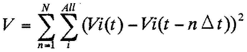
[0157] [0157]
-位置の麵 P -Position 麵 P
C(t)>1の ttS^ TtS ^ with C (t)> 1
N All N All
ρΰ ( )― ( — «厶0—尸。 一 0)) ρ ΰ () ― (— «厶 0— 尸. 1 0))
C(t)=lの C (t) = l
N N
尸 = ^ 0Ρο (ί)— 一《厶り)2 [0158] [数 10] 尸 = ^ 0Ρ ο (ί) —one << squeeze 2 [0158] [Equation 10]
• ¾¾¾fg率の S3¾ R • S3¾ R of ¾¾¾fg rate
R ^ (Ri(t) - Ri(t— " Δ i))2 R ^ (Ri (t)-Ri (t— "Δ i)) 2
[0159] なお、 C(t)は時間 tにおけるスクリーン個数、 Vi(t)はスクリーン iが時間 tにおける音声 の大きさ、 Pi(t)はスクリーン iが時間 tにおける位置、 Ri(t)はスクリーン iが時間 tにおける 表示倍率とする。 Rmaxはディスプレイ全体を 1つのスクリーンで覆った場合の表示倍 率とする。 [0159] Note that C (t) is the number of screens at time t, Vi (t) is the loudness of screen i at time t, Pi (t) is the position of screen i at time t, and Ri (t) is Let screen i be the display magnification at time t. Rmax is the display magnification when the entire display is covered with one screen.
[0160] 図 36は、安定状態を判定し、攪拌処理を行う処理を説明するためのフローチャート である。 FIG. 36 is a flowchart for explaining a process of determining a stable state and performing a stirring process.
以下の処理において、 Cはスクリーン個数の変動値、 Vは音声の大きさの変動値、 P は位置の変動値、 Rは表示倍率の変動値、 Rthreshl、 Rthresh2、 Pthreshlは閾値、 R maxはディスプレイ全体を 1つのスクリーンで覆った場合の表示倍率をそれぞれ示し ている。 In the following processing, C is the fluctuation value of the number of screens, V is the fluctuation value of the sound volume, P is the fluctuation value of the position, R is the fluctuation value of the display magnification, Rthreshl, Rthresh2, Pthreshl is the threshold value, R max is the display Each display magnification is shown when the whole is covered with one screen.
[0161] スクリーン個数の変動がなく (C=0)、音声の大きさの変動がな 、(V=0)の場合 (ST11) で、表示倍率の変動 Rが閾値 Rthreshl以下(R≤RthreshO)、スクリーン位置の変動 P が閾値 Pthreshl以下である(P≤Pthreshl)である場合 (ST12)、もしくは、表示倍率の 二乗総和比 R(t)が閾値 Rthresh2以下(R(t)≤Rthresh2)、スクリーン位置の変動 Pが閾 値 Pthreshl以下である(P≤ Pthreshl)である場合(ST13)、スクリーンが絶えず安定 状態に陥ったと判断する。 [0161] When there is no change in the number of screens (C = 0), there is no change in the sound volume, and (V = 0) (ST11), the change in display magnification R is less than the threshold Rthreshl (R≤RthreshO) When the screen position variation P is less than or equal to the threshold Pthreshl (P≤Pthreshl) (ST12), or the sum-to-square ratio R (t) of the display magnification is less than or equal to the threshold Rthresh2 (R (t) ≤Rthresh2) If the position variation P is less than or equal to the threshold value Pthreshl (P≤Pthreshl) (ST13), it is determined that the screen is constantly in a stable state.
攪拌回数 Sが閾値 Sthresh以下の場合 (S≤Sthresh)で (ST14)、攪拌処理後の経過 時間 Qが閾値 Qthresh経過している場合 (ST15)、攪拌処理を施し、攪拌回数 S、経過 時間 Qを更新 (S++、 Q=0)する(ST16、 ST17)。攪拌回数 Sが閾値 Sthreshを越える場 合 (ST14)、安定状態にある判定する (ST18)。 When the number of agitation S is less than or equal to the threshold Sthresh (S≤Sthresh) (ST14), and the elapsed time Q after the agitation process has passed the threshold Qthresh (ST15), the agitation process is performed, the number of agitation S, the elapsed time Q Is updated (S ++, Q = 0) (ST16, ST17). When the number of agitation S exceeds the threshold Sthresh (ST14), it is determined that the mixture is in a stable state (ST18).
なお、スクリーン個数が変動した場合 (C≠0)、もしくは音声の大きさが変動した場 合 (V≠0)、攪拌回数 S、経過時間 Qをクリアする (ST19)。 If the number of screens fluctuates (C ≠ 0) or the sound volume fluctuates (V ≠ 0), the number of agitation S and elapsed time Q are cleared (ST19).
これにより、表示倍率の変動値 Rが小さい状態に安定した場合に、この配置状態か らの脱却を促すことが可能となる。また、安定状態を判定して力 攪拌処理を行うた め、不用意な攪拌処理をなくすことが可能となる。 As a result, when the variation value R of the display magnification is stabilized in a small state, it is possible to prompt a departure from this arrangement state. In addition, to determine the stable state and perform force agitation processing Therefore, it is possible to eliminate an inadvertent stirring process.
[0162] なお、スクリーン個数の変動 C、音声の大きさの変動 V、位置の変動 P、表示倍率の 変動 および時間 tにおける表示倍率の二乗総和比は、以下の式で与えられる。 [0162] It should be noted that the variation C of the number of screens, the variation V of the sound volume V, the variation P of the position, the variation of the display magnification, and the square sum ratio of the display magnification at time t are given by the following equations.
[0163] [数 11] [0163] [Equation 11]
.スクリーン «Β [の « C

[0164] [数 12] [0164] [Equation 12]
•音声の大きさの麵 V
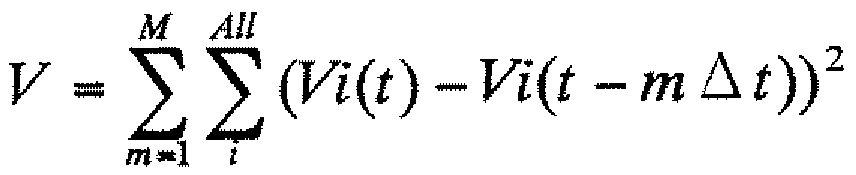
[0165] [数 13] [0165] [Equation 13]
•位置の魏 P • Position 魏 P
C(t)>1 C (t)> 1
M All M All
P = Τ 2 ((Pi(t)― P0 (0)― (Pi(t— m△ ί)— Ρ0 (ί - w Δ i P = Τ 2 ((Pi (t) ― P 0 (0) ― (Pi (t— m △ ί)) Ρ 0 (ί-w Δ i
C(t)=1
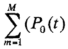
[0166] [数 14] [0166] [Equation 14]
• 率の趣 R
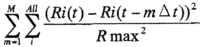
[0167] [数 15] [0167] [Equation 15]
畤 is tにおける表 率の: gi^a比 Table ratio of 表 is t: gi ^ a ratio
R(t) =R (t) =
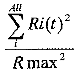
[0169] 位置の変動 Pの算出において、相対値を用いることにより、下記の場合において、 対応が可能となる。 [0169] By using relative values in the calculation of position fluctuation P, the following cases can be handled.
[0170] 図 37の例は、 2つのスクリーンが安定した相対位置関係にあり、 1つの塊として、上 下に移動する場合を示して 、る。 [0170] The example in Fig. 37 shows a case where two screens are in a stable relative positional relationship and move up and down as one lump.
局所安定の判定にぉ ヽて、単純に絶対的な位置のみを用いて判定を行った場合、 全体として上下に移動しているため、局所安定状態には該当しないという結果を得る また、振動状態という判定においても、上下の移動距離が大きいため、振動状態と 判定することは困難となる。 If the determination is made using only the absolute position for the determination of local stability, the result is that it does not fall into the local stable state because it moves up and down as a whole. Even in this determination, it is difficult to determine the vibration state because the vertical movement distance is large.
これに対して、本第 3の実施形態にように、相対位置を用いて判定を行うことにより、 局所安定状態と判定することが可能となる。 On the other hand, as in the third embodiment, it is possible to determine the local stable state by performing the determination using the relative position.
[0171] 図 38A〜図 38Eは、攪拌用のスクリーンを示す図であって、挙動を説明するための 図である。 [0171] Figs. 38A to 38E are diagrams illustrating a stirring screen and are diagrams for explaining the behavior.
[0172] 画面上に仮の中心を配し、各中心いおいて、表示倍率 (Rmin)を算出する。各表示 倍率 (Rmin)の内、最も小さい値を取る位置に攪拌用のスクリーンを生成し、 Uステツ プ状態 (U≥l)を更新した後で、攪拌用のスクリーンを廃棄する。この攪拌用のスクリ ーンは視覚的に見得ないものとする。 [0172] A temporary center is placed on the screen, and the display magnification (Rmin) is calculated at each center. A screen for stirring is created at the position where the smallest value is displayed in each display magnification (Rmin), and after updating the U step state (U≥l), the screen for stirring is discarded. This stirring screen shall not be visible visually.
また、この攪拌処理自体をユーザに見得ないものとしても良い。 1度で効果が現れ ない場合、数度繰り返す。この場合、攪拌用のスクリーンの生成位置は、前回と異な る位置に設定するものとする。 The stirring process itself may not be visible to the user. If there is no effect once, repeat several times. In this case, the generation position of the stirring screen shall be set to a position different from the previous time.
攪拌処理後は、安定するまでに時間を要する。このため、この安定していない状態 で、攪拌処理実行有無の判定に入れると、攪拌処理回数 Sが即座にクリア (S=0)にな る。つまり、処理が効果的に効いた力否かに関わらず、効果的に効いたと判断してし まうことになる。このため、経過時間 Qは、 Qthreshステップ経過してから、判定を再開 するものとする。 After stirring, it takes time to stabilize. For this reason, if it is determined whether or not the stirring process is executed in this unstable state, the number of stirring processes S is immediately cleared (S = 0). In other words, it is judged that the treatment is effective regardless of whether the treatment is effective or not. It will be. For this reason, the elapsed time Q shall be restarted after Qthresh steps have elapsed.
[0173] [数 16] [0173] [Equation 16]
R min(kl = min(R(k /)) R min (kl = min (R (k /))
ゾ'" Zo '"
[0174] [数 17] [0174] [Equation 17]
R(k) = mm(i? min(^:')) R (k) = mm (i? Min (^: '))
[0175] 図 38A〜図 38Eは、分力りやすくするための、攪拌用のスクリーンを図示している。 [0175] FIGS. 38A to 38E illustrate a screen for stirring to facilitate the application of force.
図 38A〜図 38Eの画面図において、左(図 38A)から右(図 38E)に時間が進む。 図 38Aにおいて局所安定状態であると判定された場合に、図 38Bに示すように、 攪拌処理に入る。攪拌用のスクリーンが生成される。位置関係により、近傍のスクリー ンのサイズが小さくなつた。 In the screen diagrams of FIGS. 38A to 38E, time advances from the left (FIG. 38A) to the right (FIG. 38E). When it is determined in FIG. 38A that it is in the local stable state, as shown in FIG. 38B, the stirring process is started. A screen for stirring is generated. Due to the positional relationship, the size of the nearby screen became smaller.
図 38Cにおいて状態更新する。表示倍率の二乗総和比が大きくなるように配置を 更新する。 The state is updated in Fig. 38C. Update the layout so that the square sum ratio of the display magnification is increased.
図 38Dにおいて、状態更新する。表示倍率の二乗総和比が大きくなるように更に、 配置を更新する。 In FIG. 38D, the state is updated. Further, the layout is updated so that the square sum ratio of the display magnification is increased.
そして、図 38Dにおいて攪拌処理が終了(状態更新)する。攪拌用のスクリーンを 消滅する。表示倍率の二乗総和比が大きくなるように配置を更新する。 Then, in FIG. 38D, the stirring process ends (state update). Disappear the stirring screen. The arrangement is updated so that the square sum ratio of the display magnification is increased.
図 38Aと図 38Eとを比較した場合、スクリーンの位置関係が変化し、表示倍率の二 乗総和比 R(t)=0.637197から 0.884781に増大して!/、ることが分かる。 When comparing FIG. 38A and FIG. 38E, it can be seen that the positional relationship of the screen changes and the square sum ratio R (t) of the display magnification increases from 0.637197 to 0.884781! /.
[0176] なお、本第 3の実施形態にぉ 、て、上述したようにサイズおよび表示形態が制御さ れる表示部 510におけるスクリーン表示制御については、第 2の実施形態において、 図 27〜図 31に関連付けて説明した表示制御と同様であることから、ここではその説 明を省略する。 Note that in the third embodiment, the screen display control in the display unit 510 in which the size and the display form are controlled as described above will be described with reference to FIGS. 27 to 31 in the second embodiment. Since this is the same as the display control described in association with, the description is omitted here.
[0177] 以上説明したように、本第 3の実施形態によれば、送信元となるエンコード装置 40 は、送信元は、画面上、指示した位置にスクリーンが存在する場合、対応する指示情 報、スクリーン情報、音量情報を生成し、同通信中の相手に対して送出する機能を有 し、デコード装置 50は、マルチスクリーンを表示する機能を有し、スクリーン中心間を 結ぶ線分、基準形状の厚さ、音声の大きさに基づいて、スクリーンの表示倍率を算出 し、この表示倍率に基づいてスクリーンの移動、新規生成を制御することにより、画面 上に複数のスクリーンを最適に形成し、画面上のスクリーンの配置状態が振動状態 にある力否かを判定し、振動状態にある場合に固定ィ匕するとともに、安定状態を判定 し、攪拌処理を施すことにより、局所安定状態を解消する機能を有することから、スク リーンのサイズ力 音量の大きさ、およびスクリーン数に応じて、適応的にサイズを変 動させることができる。 [0177] As described above, according to the third embodiment, the encoding device 40 serving as the transmission source has the corresponding instruction information when the transmission source has a screen at the indicated position on the screen. It has a function to generate screen information and volume information and send it to the other party during the communication. The decoding device 50 has a function of displaying a multi-screen, calculates the display magnification of the screen based on the line connecting the centers of the screens, the thickness of the reference shape, and the volume of the sound. By controlling the movement and new generation of screens based on the above, multiple screens are optimally formed on the screen, and it is determined whether the screen layout on the screen is in a vibrating state or not. In some cases, it has a function to cancel the local stable state by determining the stable state and applying a stirring process, so that the size power of the screen, the volume, and the number of screens The size can be changed adaptively.
また、スクリーンの動きが連続的になり、異なる形状であっても、最適なサイズに配 置することが可能となる利点がある。 In addition, there is an advantage that the movement of the screen is continuous, and it is possible to arrange the screen in an optimal size even if the shape is different.
さらに、振動を停止することにより、煩わしさをなくすことが可能となる。 Furthermore, the troublesomeness can be eliminated by stopping the vibration.
また、局所安定状態を解消することにより、スクリーンを大きくする。 In addition, the screen is enlarged by eliminating the local stable state.
また、安定状態であるか否かを判定するため、不用意な攪拌処理を行う必要がない という利点がある。 Moreover, since it is determined whether it is a stable state, there exists an advantage that it is not necessary to perform careless stirring processing.
その結果、複数端末の接続時であっても、通話中の相手を確認しやすぐまた、画 像 (スクリーン)は重ならな 、ように制御されることから、会話して 、る全員の状態が一 目で確認することができる。また、新たな参加人にも容易に対応することができる。 As a result, even when multiple terminals are connected, the image (screen) is controlled so that the image (screen) does not overlap as soon as the other party is talking. Can be confirmed at a glance. In addition, new participants can be easily accommodated.
[0178] <第 4実施形態 > [0178] <Fourth embodiment>
図 39は、本発明の第 4の実施形態に係る携帯通信端末の構成例を示す図であつ て、受信側のデコード装置を示すブロック図である。 FIG. 39 is a diagram showing a configuration example of a mobile communication terminal according to the fourth embodiment of the present invention, and is a block diagram showing a decoding device on the reception side.
[0179] 前述した第 2および第 3の実施形態においては、ユーザが操作することなぐ音量 の大きさや表示すべき表示画像エリア (スクリーン)の数等の状況に応じて適応的に、 最適に表示画像エリア (スクリーン)のサイズ、位置を更新することができ、し力も表示 画像エリアの再配置 (移動)が連続的になり、異なる形状であっても最適なサイズで配 置することが可能であり、また、振動を停止することにより、煩わしさをなくすことが可 能となり、局所安定状態を解消することが可能な携帯通信端末を実現している。 [0179] In the second and third embodiments described above, the optimum display is performed adaptively according to the situation such as the volume level that the user does not operate and the number of display image areas (screens) to be displayed. The size and position of the image area (screen) can be updated, and the force can be displayed. The image area can be rearranged (moved) continuously, and even with different shapes, it can be placed at the optimum size. In addition, by stopping the vibration, it is possible to eliminate inconvenience, and a mobile communication terminal capable of eliminating the local stable state is realized.
[0180] ただし、たとえば送信側である撮影者力カメラをバーンなどして被写体を変える場 合、その被写体を受信側である相手に見せたいがためである。その際に、必ずしも撮 影者は話しているとは限らない。このため、バーンした後に、何力しら話さないといけ ないことになる。 [0180] However, for example, when the subject is changed by burning the photographer-powered camera on the transmission side, it is desired to show the subject to the other party on the reception side. Do not necessarily take Shadow casts are not always talking. For this reason, after burning, you have to talk about how much you can.
たとえば、何を購入してくれば良いか選択してもらうために、画像を送っている場合 、絶えず撮影者が話しをしつづけることはできない。しかし、受信した画像自体はそ の間絶えず視認できる大きさのスクリーンである必要がある。 For example, if you are sending an image to choose what to buy, the photographer can't keep talking. However, the received image itself must be a screen that is sized so that it can be seen continuously.
[0181] そこで、本第 4の実施形態においては、ユーザが操作することなぐ音量の大きさや 表示すべき表示画像エリア (スクリーン)の数等の状況に応じて適応的に、最適に表 示画像エリア (スクリーン)のサイズ、位置を更新することができ、しかも表示画像エリ ァの再配置 (移動)が連続的になり、異なる形状であっても最適なサイズで配置するこ とが可能であり、送信者が見せたい画像を撮像した際に、送信者が何ら新たな操作 を追加することなぐ受信側では即座にその画像を大きく見せることが可能となる携帯 通信端末を実現している。 [0181] Therefore, in the fourth embodiment, the display image is adaptively and optimally adapted according to the situation such as the volume level that the user does not operate and the number of display image areas (screens) to be displayed. The size and position of the area (screen) can be updated, and the display image area can be rearranged (moved) continuously, so that different shapes can be arranged at the optimum size. When the image that the sender wants to view is taken, a mobile communication terminal is realized that allows the receiver to immediately display the image larger without adding any new operation.
[0182] 本第 4の実施形態に係る携帯通信端末 10Cにおけるデコード装置 60も、基本的に 、通信相手 (送信元)のエンコード装置力 送信されネットワークを介して受信した音 声データ、画像データを再生する機能を有する。 [0182] The decoding device 60 in the mobile communication terminal 10C according to the fourth embodiment basically also uses the encoding device power of the communication partner (transmission source) to transmit the audio data and image data received via the network. It has a function to play.
デコード装置 60は、たとえば多地点通信を行っている場合に、受信画像の制御情 報に基づいて特定エリアである顔を含む画像を、使用するスクリーン (サイズが制御さ れた表示エリア)を選択して表示し、音声を発する機能を有する。 For example, when performing multipoint communication, the decoding device 60 selects a screen (a display area whose size is controlled) to use an image including a face as a specific area based on the control information of the received image. Display, and has a function of emitting sound.
デコード装置 60は、このスクリーンの表示に際し、デッドゾーンをなくした円形 (楕円 形を含む概念である)ウィンドウにて分割する機能を有する。 The decoding device 60 has a function of dividing the screen in a circular (concept including an ellipse) window that eliminates the dead zone when the screen is displayed.
第 1の実施形態等において説明したが、円形 (楕円形)ウィンドウに分割するように構 成したのは、以下の理由による。 As described in the first embodiment, etc., the reason why it is configured to be divided into circular (elliptical) windows is as follows.
一般的に、画面の分割は、長方形で行っていた。人間の顔は基本的に楕円形であ り、長方形の四隅はデットゾーンとなる。このデッドゾーンが、顔を表示するエリアを結 果的に狭く(小さく)している。 In general, the screen is divided into rectangles. The human face is basically oval, and the four corners of the rectangle are dead zones. This dead zone results in a narrower (smaller) area for displaying the face.
よって、本実施形態においては、このデッドゾーンをなくした円形 (楕円形)ウィンド ゥにて分割するように構成して 、る。 Therefore, in the present embodiment, it is configured to divide in a circular (elliptical) window from which this dead zone is eliminated.
[0183] 図 39のデコード装置 600は、ネットワークと無線通信可能で送信元から送信された 音声データ、画像 (映像)データ、制御情報や指示情報、スクリーン情報、音量情報等 を含むパケットを受信するネットワークインタフェース(IZF) 601、ネットワークインタ フェース 101で受信されたパケットを解析し、音声データ、画像データ、送信元ァドレ ス、制御情報 (天地情報や指示情報等)を抽出する受信パケット解析部 602、受信パ ケット解析部 602により抽出された音声データを復号する音声復号処理部 603、受 信パケット解析部 602により抽出された映像データを復号する映像復号処理部 604 、復号映像処理部 604により復号された映像データを蓄積する映像蓄積部 605、映 像蓄積部 605に蓄積された映像データおよび映像復号処理部 604により復号された 映像信号に基づいて送信側のカメラ (撮像)操作のシーンチェンジを推定するシーン チェンジ判定部 606、映像蓄積部 605に蓄積された映像データおよび映像復号処 理部 604により復号された映像信号に基づいて送信側のカメラ (撮像)操作のバーン 操作を推定するバーン判定部 607、映像蓄積部 605に蓄積された映像データおよ び映像復号処理部 604により復号された映像信号に基づいて送信側のカメラ (撮像) 操作の回転操作を推定する回転判定部 608、映像復号処理部 604により復号され た映像信号に基づ 、て画像の合焦状態を判定する合焦判定部 609、シーンチェン ジ判定部 606、バーン判定部 607、回転判定部 608、および合焦判定部 609の判定 結果に基づいて受信画像の注目度 (V )を推定する注目度推定部 610、推定した [0183] The decoding device 600 of FIG. 39 is wirelessly communicable with the network and transmitted from the transmission source. Network interface (IZF) 601 that receives packets including audio data, image (video) data, control information and instruction information, screen information, volume information, etc. Received packet analysis unit 602 for extracting image data, transmission source address, control information (top and bottom information, instruction information, etc.), audio decoding processing unit 603 for decoding audio data extracted by the received packet analysis unit 602, reception Video decoding processing unit 604 for decoding video data extracted by the packet analysis unit 602, video storage unit 605 for storing video data decoded by the decoded video processing unit 604, video data stored in the video storage unit 605, and Based on the video signal decoded by the video decoding processing unit 604, a scene for estimating a scene change of the camera (imaging) operation on the transmission side is estimated. A change determination unit 606, a burn determination unit 607 for estimating a burn operation of a camera (imaging) operation on the transmission side based on the video data stored in the video storage unit 605 and the video signal decoded by the video decoding processing unit 604, Rotation determination unit 608 for estimating the rotation operation of the camera (imaging) operation on the transmission side based on the video data stored in video storage unit 605 and the video signal decoded by video decoding processing unit 604, video decoding processing unit Based on the video signal decoded by 604, the in-focus determining unit 609, the scene change determining unit 606, the burn determining unit 607, the rotation determining unit 608, and the in-focus determining unit 609 that determine the in-focus state of the image. Attention level estimation unit 610 that estimates the attention level (V) of the received image based on the determination result,
att att
注目度注目度 (V )と、受信音量 (V )に基づ 、て画像を表示すべき表示エリア (ス Attention level Based on the attention level (V) and the reception volume (V)
att rec att rec
クリーン)の表示倍率用係数 (V )を算出する表示倍率用係数合成部 611、算出し Display magnification factor composition unit 611 that calculates the display magnification factor (V)
syn syn
た表示倍率用係数 (V )に基づいてスクリーンの表示倍率 (R)を算出する表示倍率 Display magnification that calculates the screen display magnification (R) based on the display magnification factor (V)
syn syn
算出部 612、映像復号処理部 604により復号された映像信号を算出した表示倍率に 従って合成するマルチスクリーン合成部 613、マルチスクリーン合成部 613の合成画 像を表示する LCD等の表示部(画像出力部) 614、および音声復号処理部 603で復 号された音声を所定の音量で発音するスピーカ等の音声出力部 615を有する。 このように、本第 4の実施形態においては、注目度推定部 610は、受信画像の動き ベクトル、符号化の増大、および周波数成分に基づ!ヽて、受信画像の注目度 (V ) Multi-screen synthesis unit 613 that synthesizes the video signal decoded by video calculation processing unit 612 and video decoding processing unit 604 according to the calculated display magnification, and a display unit such as an LCD that displays a composite image of multi-screen synthesis unit 613 (image output 614, and a sound output unit 615 such as a speaker that produces the sound decoded by the sound decoding processing unit 603 at a predetermined volume. As described above, in the fourth embodiment, the attention level estimation unit 610 is based on the motion vector of the received image, the increase in encoding, and the frequency component! The attention level (V) of the received image.
att を推定する。 Estimate att.
表示倍率用係数合成部 611は、注目度 (V )と、受信音量 (V )に基づいて、スク The display magnification factor composition unit 611 performs the scoring based on the attention level (V) and the reception volume (V).
att rec リーンの表示倍率用係数 (V )を算出する。 att rec Calculate the lean display magnification factor (V).
syn syn
また、表示倍率算出部 612は、表示倍率用係数 (V )に基づいてスクリーンの表示 The display magnification calculation unit 612 displays the screen based on the display magnification coefficient (V).
syn syn
倍率 (R)を算出する。 Calculate the magnification (R).
また、判定部 606〜609は、受信画像の動きベクトル、符号化の変動に基づいて、 送信側のカメラ操作 (バーン、回転、シーンチェンジ)を推定する。 Further, the determination units 606 to 609 estimate the camera operation (burn, rotation, scene change) on the transmission side based on the motion vector of the received image and the variation in encoding.
そして、所定の操作があつたと判定した場合、注目度推定部 610は、判定された操 作 (終了)後に受信する画像は、注目度が高 、と推定する。 If it is determined that a predetermined operation has been performed, attention level estimation section 610 estimates that the image received after the determined operation (end) has a high level of attention.
また、表示倍率用係数合成部 611は、注目度 (V )と、受信音量 (V )とから、大き Also, the display magnification factor composition unit 611 calculates the magnitude from the attention level (V) and the reception volume (V).
stt rec stt rec
い方を選択する。 Select the one you want.
[0185] 以下に、図 39のデコード装置 60の動作について説明する。 Hereinafter, the operation of the decoding device 60 of FIG. 39 will be described.
[0186] 復号された映像データ (M(t))に基づき、前時刻の映像データ (M(t-n Δ t) )に基づ いて、シーンチェンジ判定部 606、バーン判定部 607、回転判定部 608により、各々 シーンチェンジの発生の有無、バーンの発生の有無、回転の発生の有無を判定する 具体的には、たとえば、映像間の動きベクトルを検出し、画面全体の動きベクトルが 一様に一方向に揃っており、そのベクトル長が閾値以上の場合、バーンと判定する。 また、ある一点を中心にベクトルが渦状に配している場合、回転と判定する。ベクトル が揃わず、符号量が増大している場合に、シーンチェンジと判定する。 Based on the decoded video data (M (t)), based on the previous video data (M (tn Δt)), the scene change determination unit 606, the burn determination unit 607, and the rotation determination unit 608 To determine whether a scene change has occurred, whether a burn has occurred, and whether a rotation has occurred. Specifically, for example, a motion vector between videos is detected, and the motion vector of the entire screen is uniform. If they are aligned in the direction and the vector length is equal to or greater than the threshold value, it is determined that the burn has occurred. Further, when the vector is arranged in a vortex around a certain point, it is determined that the rotation. A scene change is determined when the vectors are not aligned and the amount of code increases.
[0187] 注目度算出部 610は、シーンチェンジ判定部 606、バーン判定部 607、回転判定 部 608の判定結果、および合焦判定部 609の判定結果に基づいて、シーンチェンジ 、バーン、回転いずれかが起こっている場合、それが終了した後に注目すべき映像 を受信すると推測し、終了後、合焦している映像を受信した場合に、この映像以降を 注目すべき映像と推定する。 [0187] Attention level calculation section 610 is either scene change, burn, or rotation based on the determination result of scene change determination section 606, burn determination section 607, rotation determination section 608, and the determination result of focus determination section 609. If this occurs, it is assumed that the video to be watched will be received after it has been completed, and if the focused video is received after the video is finished, the video after this video is estimated as the video to be watched.
なお、合焦判定部 609は、受信映像の周波数成分を算出し、周波数成分の最大値 が閾値以上であるかを判定することにより、合焦判定を行う。 Note that the focus determination unit 609 performs the focus determination by calculating the frequency component of the received video and determining whether the maximum value of the frequency component is greater than or equal to the threshold value.
表示倍率係数合成部 611は、次のように受信した音声 (V )と、注目度 (V )に基 The display magnification factor synthesis unit 611 is based on the received voice (V) and the attention level (V) as follows.
rec att づいて表示倍率係数 (V )算出する。 Calculate the display magnification factor (V) based on rec att.
syn syn
[0188] [数 18] ϊ7 = max( V rec , r attノ [0188] [Equation 18] ϊ 7 = max (V rec, r att
[0189] そして、表示倍率算出部 612は、次のように、表示倍率係数 (V )から表示倍率 (R syn [0189] Then, the display magnification calculator 612 calculates the display magnification (R syn from the display magnification coefficient (V) as follows.
)を算出する。 ) Is calculated.
[0190] [数 19] D [0190] [Equation 19] D
[0191] 各スクリーンの表示倍率 (R)に基づいて、画面上にスクリーンを成形し、画像出力 部としての表示部 614にて表示出力する。また、復号された音声は、音声出力部 61 5にて再生される。 [0191] Based on the display magnification (R) of each screen, a screen is formed on the screen, and is displayed and output by a display unit 614 as an image output unit. The decoded sound is reproduced by the sound output unit 615.
[0192] 図 40は、本第 4の実施形態の主要動作を示すフローチャートである。 FIG. 40 is a flowchart showing the main operation of the fourth embodiment.
[0193] この場合、画像を受信して(ST21)、シーンチェンジ、バーン、回転を判別した場合 [0193] In this case, when an image is received (ST21) and scene change, burn, or rotation is determined
(ST22〜ST24)、注目度フラグ(bAtentFlg)を TRUEとする(ST25)。 (ST22 to ST24), the attention level flag (bAtentFlg) is set to TRUE (ST25).
注目度フラグ (bAtentFlg)が TRUEの場合 (ST26)、映像の周半数成分 (F )が閾 max 値 (F )を越えているか否かを判定し (ST27)、越えている場合、合焦と判定し、時 When the attention flag (bAtentFlg) is TRUE (ST26), it is determined whether the video half-frequency component (F) exceeds the threshold max value (F) (ST27). Judgment and time
Threa Threa
間を初期化し (T =t)、注目度 (V )を関数 (g ( )にて算出する (ST28〜ST33)。 The interval is initialized (T = t), and the degree of attention (V) is calculated by the function (g () (ST28 to ST33).
stt att stt att
関数 (g ( '))は、 0で最大となり、時間経過に伴い減衰する関数である。 The function (g (')) is a function that becomes maximum at 0 and decays with time.
[0194] [数 20] [0194] [Equation 20]
Ku = g(t ) Ku = g (t)
[0195] 図 41A〜図 41Cは、端末 Aと端末 B力もの撮像画像を端末 Cの画面にて表示して いる場合を示す図である。 FIG. 41A to FIG. 41C are diagrams showing a case where captured images of terminal A and terminal B are displayed on the screen of terminal C.
この場合、端末 Aからは絶えず一定の音量の声が流れて ヽるものとする。 端末 Bでは、時間 tから時間 t+ A tの間にて、撮像するカメラを切り替えた。これによ り、時間 t+ A tにて撮像される画像が、人から魚になった。 In this case, it is assumed that a constant sound volume is heard from terminal A. In terminal B, the camera for imaging was switched between time t and time t + At. As a result, the image captured at time t + A t changed from a person to a fish.
この場合、端末 B力 の画像の注目度は上がったと判断し、端末 Cの画面には、時 間 t+ A tにおける端末 Bのスクリーンは、時間 tにおける端末 Bのスクリーンよりサイズ が大きくなる。 そのまま時間 t+N A tに経過した場合、注目度は少しずつ低下すると推測し、時間 t+N A tにおける端末 Bのスクリーンは、時間 t+ A tのスクリーンサイズに比べ小さく する。 In this case, it is determined that the attention level of the image of the terminal B power has increased, and the screen of the terminal C on the screen of the terminal C is larger in size than the screen of the terminal B at the time t + At. If the time t + NA t elapses, it is assumed that the degree of attention will gradually decrease, and the screen of terminal B at time t + NA t is made smaller than the screen size at time t + At.
[0196] 図 42A〜図 42Cは、端末 Aと端末 B力もの撮像画像を端末 Cの画面にて表示して [0196] Figs. 42A to 42C show captured images of terminal A and terminal B on the screen of terminal C.
V、る他の例を示す図である。 It is a figure which shows the other example of V.
この場合、端末 Aからは絶えず一定の音量の声が流れて ヽるものとする。 端末 Bでは、時間 tから時間 t+N A tの間にて、撮像するカメラをバーンした。時間 t +N A tにて撮像される画像力 人間から魚になった。しかし、時間 t+N A tでは、ぼ けた画像となっている。時間 t+ (N+ l) A tにて合焦する。 In this case, it is assumed that a constant sound volume is heard from terminal A. In terminal B, the camera for imaging was burned between time t and time t + NAt. Image power picked up at time t + NA t Changed from human to fish. However, at time t + NAt, the image is blurred. Focus at time t + (N + l) At.
これに対して、端末 Cでの画面は、時間 t+ (N+ 1) A tの合焦に共に、端末 Bのス クリーン力 時間 t+N A tのスクリーンより大きくなる。 On the other hand, the screen at terminal C is larger than the screen at terminal B with screen force time t + NAt as the time t + (N + 1) At is focused.
時間 t+ A tのバーンの検知により、注目画像が来ることを予測し、その後、合焦の 検知により、時間 t+ (N+ 1) A tの画像を注目度の高い画像と判断し、注目度の値 を大きくする。 By detecting the burn at time t + A t, it is predicted that the image of interest will come.After that, by detecting the focus, the image at time t + (N + 1) A t is judged as an image with high attention. Increase the value.
[0197] 図 43および図 44は、シーンチェンジによる注目度 (V )の変化と、受信音量 (V ) att rec の変化、および表示倍率用係数 (V )の変動を示した図である。 FIG. 43 and FIG. 44 are diagrams showing a change in the degree of attention (V) due to a scene change, a change in the reception volume (V) att rec, and a change in the display magnification factor (V).
syn syn
図 43では、時間 tにて符号量の増大があり、および動きベクトル(図なし)から、シ In FIG. 43, there is an increase in the code amount at time t, and from the motion vector (not shown),
0 0
ーンチェンジが生じたと判定する。注目度 (V )は時間 tに最大値となる。時間経過 att 0 It is determined that an event change has occurred. Attention (V) reaches its maximum at time t. Elapsed time att 0
とともに、注目度 (V )は減衰する。表示倍率用係数合成部にて、表示倍率用係数( att At the same time, the degree of attention (V) decreases. Display magnification factor (att
V )を得る。時間 tから tの区間は、注目度 (V )が受信音量 (V )より大きいため、 syn 0 1 att rec V) get. Syn 0 1 att rec in the interval from t to t because the degree of attention (V) is higher than the reception volume (V)
V =v とする。 Let V = v.
syn att syn att
図 44も同様である。受信音量 (V )の変動が異なり、シーンチェンジ時(時間 t )に rec 2 高い。表示倍率用係数 (V )は、時間 tから tの区間は、注目度 (V )が受信音量( syn 2 3 att The same applies to FIG. The reception volume (V) varies and rec 2 is high at the scene change (time t). The coefficient for display magnification (V) is the amount of attention (V) in the interval from time t to t.
V )より大きいため、 V =v とする。 V = v because it is larger than V).
rec syn att rec syn att
表示倍率用係数 (V )の算出において最大値 (max)演算にて注目度 (V )と受信 syn att 音量 )を合成しているため、受信音量が高い場合に、注目度が上がった場合に rec When calculating the display magnification factor (V), the maximum value (max) is used to synthesize the attention level (V) and the reception syn att volume). rec
、更に表示倍率用係数 (V )が増大しすぎることを制限することとなっており、声の大 syn In addition, the display magnification factor (V) is restricted from increasing too much,
きい人の撮像したものだけが、シーンチェンジ、バーン、回転など注目度が高いと推 測された際のスクリーンサイズが極端に大きくなることを防ぐことが可能となる。 It is assumed that only the images taken by a person with a high degree of attention, such as scene changes, burns, and rotations. It becomes possible to prevent the screen size when measured from becoming extremely large.
[0198] 以上説明したように、本第 4の実施形態によれば、デコード装置 60は、画像を表示 する表示部 114と、受信画像の注目度を推定する注目度推定部 610と、推定した注 目度と、受信音量に基づいて表示エリアの表示倍率用係数を算出する表倍率用係 数合成部 611と、算出した表示倍率用係数に基づいて表示エリアの表示倍率を算 出する表示倍率算出部 612と、を有するとともに、マルチスクリーンを表示する機能を 有し、スクリーン中心間を結ぶ線分、基準形状の厚さ、音声の大きさに基づいて、スク リーンの表示倍率を算出し、この表示倍率に基づいてスクリーンの移動、新規生成を 制御することにより、画面上に複数のスクリーンを最適に形成する機能を有することか ら、スクリーンのサイズ力 音量の大きさ、およびスクリーン数に応じて、適応的にサイ ズを変動させることができる。 As described above, according to the fourth embodiment, the decoding device 60 estimates the display unit 114 that displays an image, the attention level estimation unit 610 that estimates the attention level of a received image, and the estimation. Note: The table magnification factor composition unit 611 that calculates the display area display magnification coefficient based on the target degree and the received volume, and the display magnification that calculates the display area display magnification based on the calculated display magnification coefficient A calculation unit 612 and a function of displaying a multi-screen, calculating the display magnification of the screen based on the line segment connecting the center of the screen, the thickness of the reference shape, and the volume of the sound, By controlling the movement and new generation of the screen based on this display magnification, it has a function to optimally form multiple screens on the screen, so it can respond to the size, volume, and number of screens. Therefore, the size can be changed adaptively.
また、スクリーンの動きが連続的になり、異なる形状であっても、最適なサイズに配 置することが可能となる利点がある。 In addition, there is an advantage that the movement of the screen is continuous, and it is possible to arrange the screen in an optimal size even if the shape is different.
また、送信者が見せたい画像を撮像した際に、送信者が何ら新たな操作を追加す ることなく、(また、送信者が声を発すことなぐ)受信側では即座にその画像 (スクリー ンサイズ)を大きく見せることが可能となる。 In addition, when the image that the sender wants to show is captured, the receiver does not add any new operations (and the sender does not speak), and the receiver immediately ) Can be shown larger.
その結果、複数端末の接続時であっても、通話中の相手を確認しやすぐまた、画 像 (スクリーン)は重ならな 、ように制御されることから、会話して 、る全員の状態が一 目で確認することができる。また、新たな参加人にも容易に対応することができる。 As a result, even when multiple terminals are connected, the image (screen) is controlled so that the image (screen) does not overlap as soon as the other party is talking. Can be confirmed at a glance. In addition, new participants can be easily accommodated.
[0199] <第 5実施形態 > [0199] <Fifth Embodiment>
[0200] 図 45および図 46は、本発明の第 5の実施形態に係る携帯通信端末の構成例を示 す図であって、図 45はエンコード装置を示すブロック図であり、図 46はデコード装置 を示すブロック図である。 45 and 46 are diagrams showing a configuration example of the mobile communication terminal according to the fifth embodiment of the present invention. FIG. 45 is a block diagram showing an encoding device, and FIG. 46 is a decoding diagram. It is a block diagram which shows an apparatus.
[0201] 本第 5の実施形態が上述した第 4の実施形態と異なる点は、送信側と受信側に処 理を分散したことにある。 [0201] The difference of the fifth embodiment from the fourth embodiment described above is that the processing is distributed to the transmission side and the reception side.
[0202] 本第 5の実施形態に係る携帯端末装置 10Dは、エンコード装置 70とデコード装置[0202] The mobile terminal device 10D according to the fifth embodiment includes an encoding device 70 and a decoding device.
80を有する。 Has 80.
[0203] 本第 5の実施形態に係るエンコード装置 70は、前述各実施形態と同様に、符号ィ匕 した音声データ、画像データを、受信側端末に対する指示情報や画像の天地情報 等を付加してパケットとしてネットワークに送信する機能を有する。 [0203] The encoding apparatus 70 according to the fifth embodiment is similar to each of the embodiments described above. It has a function to transmit the audio data and image data to the network as packets by adding instruction information for the receiving terminal and image top / bottom information.
音声データおよび画像データに付加される送信元の指示情報は、指示された画像 の送信元の識別する情報 (たとえ、 IPアドレス、 MACアドレス)と、受信した画像上の 位置を示す位置情報とを含む。 The instruction information of the transmission source added to the audio data and the image data includes information for identifying the transmission source of the instructed image (for example, IP address, MAC address) and position information indicating the position on the received image. Including.
送信元となるエンコード装置 70は、送信元は、画面上、指示した位置にスクリーン が存在する場合、対応する指示情報、スクリーン情報、音量情報を生成し、同通信中 の相手に対して送出する機能を有する。 The encoding device 70 as a transmission source generates corresponding instruction information, screen information, and volume information when the screen exists at the specified position on the screen, and sends it to the other party during the communication. It has a function.
図 45のエンコード装置 70は、マイクロフォン等力もなる音声入力部 701、デジタル カメラ等の画像入力部 702、キー入力等が可能な操作部 703、音声入力部 701によ り入力される音声データを符号ィ匕する音声符号ィ匕処理部 704、画像入力部 702から 入力され所定エリアに切り出された画像データを符号化する画像符号化処理部 705 、撮像画像に関連付けた天地情報に基づいて、撮像画像の天地を受信側の表示部 の画面 (端末画面)の天地と一致するように補正する天地補正部 706、撮像画像から 顔のエリア (第 1特定エリア)を検出、抽出する顔エリア検出部 (顔検出部という場合も ある) 707、顔エリア検出部 707にて検出された顔エリアに基づいて使用するスクリー ン (表示すべき表示画像エリア)を判別しスクリーン情報を生成するスクリーン判定部 708、クリーン判別部 708の判定に基づいて受信画像力も該当するエリアを切り出す 切り出し処理部 709、撮像画像力も手のエリア(第 2特定エリア)を検出、抽出する手 検出部 710、顔エリア検出部 707および手検出部 710の検出結果に基づいて挙動 判定を行 、注目度情報を生成する挙動判定部 711、挙動情報を蓄積する挙動情報 蓄積部 712、操作部 703の入力情報に基づいて端末を制御する端末制御部 713、 端末制御部 713の指示に基づいて指示情報や天地情報、スクリーン情報、注目度 情報、音量情報等を含む制御情報を生成する制御情報生成部 714、画像 ·映像を 記憶する記憶部 715、符号化された音声データおよび画像データ、制御情報、端末 制御部 713の指示に基づいて記憶部 715から読み出された画像 ·映像データを送 信パケットとして生成する送信パケット生成部 716、およびネットワークと無線通信可 能で生成された送信パケットをネットワークを介して通信相手の端末やサーバに送信 するネットワークインタフェース(IZF) 717を有する。 The encoding device 70 in FIG. 45 encodes audio data input by the audio input unit 701, which has a microphone power, an image input unit 702 such as a digital camera, an operation unit 703 capable of key input, and the audio input unit 701. A voice encoding processing unit 704, an image encoding processing unit 705 that encodes image data input from the image input unit 702 and cut out into a predetermined area, and a captured image based on the top and bottom information associated with the captured image The top and bottom correction unit 706 corrects the top and bottom of the display to match the top and bottom of the display screen (terminal screen) on the receiving side, and a face area detection unit that detects and extracts the face area (first specific area) from the captured image ( 707, a screen that generates screen information by determining the screen (display image area to be displayed) to be used based on the face area detected by the face area detection unit 707 Based on the determination of the fixed unit 708 and the clean discriminating unit 708, the area corresponding to the received image force is also cut out. Based on the detection results of the detection unit 707 and the hand detection unit 710, the behavior determination is performed, the behavior determination unit 711 that generates attention information, the behavior information storage unit 712 that stores behavior information, and the input information of the operation unit 703 Terminal control unit 713 that controls the terminal, control information generation unit 714 that generates control information including instruction information, top and bottom information, screen information, attention level information, volume information, and the like based on instructions from the terminal control unit 713, image / video Storage unit 715 for storing the encoded audio data and image data, control information, and image / video data read from storage unit 715 based on the instruction of terminal control unit 713 as a transmission packet Transmission packet generation unit 716 to be generated, and transmission packets generated so that wireless communication with the network is possible is transmitted to the communication partner terminal or server via the network. Network interface (IZF) 717.
[0205] 挙動判定部 711は、顔検出部 707にて、映像上に顔を抽出した場合に、映像上の 手の動きを検知し、先に設定された動きを検出した場合、注目度を上げる。 [0205] The behavior determination unit 711 detects the movement of the hand on the video when the face detection unit 707 extracts a face on the video, and determines the attention level when detecting the previously set motion. increase.
挙動情報蓄積部 712には、顔の位置に対する手の位置の移動軌跡を表すベクトル 群が蓄積されている。 The behavior information storage unit 712 stores a vector group representing the movement locus of the hand position relative to the face position.
そして、挙動判定部 711は、顔検出部 707にて抽出された顔の座標と、手検出部 7 10にて抽出された手の座標に基づき、顔の位置に対する手の相対座標として認識し 、時間経過に対して、手の相対座標の移動ベクトルを算出し、当該移動ベクトルが、 挙動情報蓄積部 712に蓄積されているベクトルとの一致度湘関)を算出し、一致度 が閾値より大きい場合、蓄積された挙動を行っていると判定する。 Then, the behavior determination unit 711 recognizes the hand coordinates relative to the face position based on the face coordinates extracted by the face detection unit 707 and the hand coordinates extracted by the hand detection unit 710, The movement vector of the relative coordinates of the hand is calculated over time, and the movement vector calculates the degree of coincidence with the vector accumulated in the behavior information accumulation unit 712, and the degree of coincidence is greater than the threshold value. In the case, it is determined that the accumulated behavior is being performed.
[0206] デコード装置 80は、前述各実施形態と同様に、通信相手 (送信元)のエンコード装 置 20から送信されネットワークを介して受信した音声データ、画像データを再生する 機能を有する。 [0206] The decoding device 80 has a function of reproducing audio data and image data transmitted from the encoding device 20 of the communication partner (transmission source) and received via the network, as in the above-described embodiments.
デコード装置 80は、たとえば多地点通信を行っている場合に、受信画像の制御情 報に基づいて特定エリアである顔を含む画像を、使用するスクリーン (サイズが制御さ れた表示エリア)を選択して表示し、音声を発する機能を有する。 For example, when performing multipoint communication, the decoding device 80 selects a screen (a display area whose size is controlled) that uses an image including a face, which is a specific area, based on control information of the received image. Display, and has a function of emitting sound.
デコード装置 80は、このスクリーンの表示に際し、デッドゾーンをなくした円形 (楕円 形を含む概念である)ウィンドウにて分割する機能を有する。 The decoding device 80 has a function of dividing the screen by a circular window (a concept including an ellipse) from which a dead zone is eliminated.
第 1の実施形態等と同様に、円形 (楕円形)ウィンドウに分割するように構成したのは 、以下の理由による。 As in the first embodiment, etc., it is configured to be divided into circular (elliptical) windows for the following reason.
一般的に、画面の分割は、長方形で行っていた。人間の顔は基本的に楕円形であ り、長方形の四隅はデットゾーンとなる。このデッドゾーンが、顔を表示するエリアを結 果的に狭く(小さく)している。 In general, the screen is divided into rectangles. The human face is basically oval, and the four corners of the rectangle are dead zones. This dead zone results in a narrower (smaller) area for displaying the face.
よって、本実施形態においては、このデッドゾーンをなくした円形 (楕円形)ウィンド ゥにて分割するように構成して 、る。 Therefore, in the present embodiment, it is configured to divide by a circular (elliptical) window from which this dead zone is eliminated.
また、デコード装置 80は、マルチスクリーンを表示する機能を有し、スクリーン中心 間を結ぶ線分、基準形状の厚さ、音声の大きさに基づいて、スクリーンの表示倍率を 算出し、この表示倍率に基づいてスクリーンの移動、新規生成を制御することにより、 画面上に複数のスクリーンを最適に形成する機能を有する。 In addition, the decoding device 80 has a function of displaying a multi-screen, calculates a screen display magnification based on a line segment connecting the centers of the screens, a thickness of a reference shape, and a volume of sound, and displays the display magnification. By controlling screen movement, new generation based on It has a function of optimally forming a plurality of screens on the screen.
[0207] 図 46のデコード装置 80は、ネットワークと無線通信可能で送信元から送信された 音声データ、画像 (映像)データ、制御情報や指示情報、スクリーン情報、注目度情報 、音量情報等を含むパケットを受信するネットワークインタフェース (IZF) 801、キー 入力等が可能な操作部 802、ネットワークインタフェース 801で受信されたパケットを 解析し、音声データ、画像データ、送信元アドレス、制御情報 (天地情報や指示情報 等)を抽出する受信パケット解析部 803、受信パケット解析部 803により抽出された音 声データを復号する音声復号処理部 804、受信パケット解析部 803により抽出され た映像データを復号する映像復号処理部 805、映像復号処理部 805により復号され た映像データ、送信元アドレス、制御情報、スクリーン情報、サイズ情報、天地情報に 基づいて表示すべきスクリーン (表示ウィンドウ)のサイズや表示形態を制御する表示 画像制御部 806、音声復号処理部 804により復号された音声の音量を修正する音 量修正部 807、音量修正部 807で修正された音量で発音するスピーカ等の音声出 力部 808、表示画像制御部 806によりサイズや表示形態が制御された画像を補正す る画像補正部 809、画像補正部 809を介した画像を表示する LCD等の表示部(画 像出力部) 810、および操作部 802からの入力情報に基づいて表示画像制御部 80 6に制御情報 (天地情報)を与える自端末制御部 811を有する。 46 includes audio data, image (video) data, control information and instruction information, screen information, attention level information, volume information, and the like that can be wirelessly communicated with the network and transmitted from the transmission source. The network interface (IZF) 801 that receives the packet, the operation unit 802 that allows key input, etc., the packet received by the network interface 801 are analyzed, and the voice data, image data, source address, control information (top and bottom information and instructions) Received packet analysis unit 803 for extracting information, etc., audio decoding processing unit 804 for decoding audio data extracted by reception packet analysis unit 803, and video decoding process for decoding video data extracted by reception packet analysis unit 803 Unit 805, video data decoded by video decoding processing unit 805, transmission source address, control information, screen information, size information Display that controls the size and display form of the screen (display window) to be displayed based on the top and bottom information Image control unit 806, audio decoding processing unit 804 Volume correction unit 807 that corrects the volume of the decoded audio, volume correction Via an audio output unit 808 such as a speaker that produces sound at a volume corrected by the unit 807, an image correction unit 809 that corrects an image whose size and display form are controlled by the display image control unit 806, and an image correction unit 809 A display unit (image output unit) 810 for displaying an image, etc., and an own terminal control unit 811 for giving control information (top and bottom information) to the display image control unit 806 based on input information from the operation unit 802 .
[0208] なお、エンコード装置 70とデコード装置 80は、操作部 703と 802、ネットワークイン タフエース 717と 801、端末制御部 713と自端末制御部 811は共用することが可能で ある。 Note that the encoding device 70 and the decoding device 80 can share the operation units 703 and 802, the network interface 717 and 801, the terminal control unit 713, and the own terminal control unit 811.
[0209] 図 46の表示画像制御部 8306は、受信パケット解析部 803により供給される制御情 報に基づいてスクリーン情報、サイズ情報、天地情報、および指示情報を抽出する制 御情報解析部 8061、スクリーン情報に基づいて映像復号処理部 805で復号された 映像に対してマスキングを行うマスキング処理部 8062、注目度情報に基づ!/、て表示 すべきスクリーン (表示画像エリア)の表示倍率用係数を算出する表示倍率用係数合 成部 8063、表示倍率用係数合成部 8063で算出された表示倍率用係数に従ってマ スキング処理後の画像を縮小 ·拡大する縮小 ·拡大処理部 8064、表示倍率用係数 合成部 8063で算出された表示倍率用係数および天地情報に従って表示位置を算 出する表示位置算出部 8065、および表示位置算出部 8065にて得られた表示部 81 0上の位置に縮小 ·拡大処理部 3064にて得られた画像をマッピングするマッピング 処理部 8066を有する。 The display image control unit 8306 in FIG. 46 extracts a control information analysis unit 8061 that extracts screen information, size information, top and bottom information, and instruction information based on the control information supplied from the received packet analysis unit 803. Masking processing unit 8062 for masking the video decoded by the video decoding processing unit 805 based on the screen information, the display magnification factor for the screen (display image area) to be displayed based on the attention level information! Display magnification factor composition unit 8063 and display magnification factor composition unit 8063 to reduce the image after masking processing according to the display magnification factor calculated by the display magnification factor 8063 Enlargement processing unit 8064 and display magnification factor The display position is calculated according to the display magnification factor and top and bottom information calculated by the combining unit 8063. And a mapping processing unit 8066 for mapping the image obtained by the reduction / enlargement processing unit 3064 to a position on the display unit 810 obtained by the display position computing unit 8065.
[0210] 本第 5の実施形態においても、表示画像制御部 806によりサイズおよび表示形態 が制御されるスクリーンは、 1つの画面上に複数のスクリーンを表示するマルチスクリ ーンとして表示される。 Also in the fifth embodiment, the screen whose size and display form are controlled by the display image control unit 806 is displayed as a multi-screen that displays a plurality of screens on one screen.
[0211] 次に、本第 5の実施形態に係る表示画像制御部 806によりサイズおよび表示形態 が制御されるスクリーンの表示倍率の算出、新規スクリーンの生成位置の算出、スクリ ーンの移動位置の算出等については、第 2の実施形態において、図 19〜図 26等に 関連付けて説明した表示制御と同様であることから、ここではその説明を省略する。 [0211] Next, the display magnification of the screen whose size and display form are controlled by the display image control unit 806 according to the fifth embodiment, the generation position of the new screen, and the movement position of the screen are calculated. Since the calculation and the like are the same as the display control described in association with FIGS. 19 to 26 in the second embodiment, the description thereof is omitted here.
[0212] 本第 5の実施形態においては、顔検出部 707、手検出部 710、および挙動判定部 711を送信側に置き、挙動判定部 711にて判定した注目度は、制御情報として受信 側に送出している。受信側では、受信した制御情報に記載された注目度情報 (V ) [0212] In the fifth embodiment, the face detection unit 707, the hand detection unit 710, and the behavior determination unit 711 are placed on the transmission side, and the degree of attention determined by the behavior determination unit 711 is received as control information on the reception side. Is being sent to. At the receiving end, attention level information (V) written in the received control information
att att
、および、受信音量 (V )とから表示倍率用係数合成部 8063にて、表示倍率用係 , And received volume (V), display magnification factor synthesis unit 8063
rec rec
数 (V )を算出し、スクリーンを形成する。なお、送信側力も操作部 703にて、意図的 syn Calculate the number (V) and form the screen. The transmission side force is also intentionally syn
に注目度 (V )を発生することもできるものとする。 It is assumed that the degree of attention (V) can be generated.
att att
挙動情報蓄積部 712には、顔の位置に対する手の位置の移動軌跡を表すベクトル 群として蓄積し、顔検出手部 707にて検出された顔の座標と、手検出部 710にて検 出された手の座標に基づき、顔の位置に対する手の相対座標として認識し、時間経 過に対して、手の相対座標の移動ベクトルを算出し、この移動ベクトル力 挙動情報 蓄積部 712に蓄積されているベクトルとの一致度湘関)を算出し、一致度が閾値より 大きい場合、蓄積された挙動を行っていると判定する。 The behavior information accumulating unit 712 accumulates a vector group representing the movement locus of the hand position relative to the face position, and the face coordinates detected by the face detecting hand unit 707 and detected by the hand detecting unit 710. Based on the coordinates of the hand, it is recognized as the relative coordinates of the hand with respect to the face position, the movement vector of the relative coordinates of the hand is calculated over time, and the movement vector force behavior information storage unit 712 stores If the degree of coincidence is greater than the threshold, it is determined that the accumulated behavior is being performed.
[0213] 図 47A〜図 47Cは、映像力も顔が認識されている場合であって、映像内に手が入 つてきた場合に、注目度を増大させる場合を示す図である。 [0213] FIGS. 47A to 47C are diagrams showing a case where the degree of attention is increased when a face is recognized in the image power and a hand enters the image.
映像内に顔を検出できた場合、映像内に手を探索する。時間 t— A tに(上向きの) 手を検出できず、時間 tに(上向きの)手を検出できた場合に、注目度 V を増加する If a face can be detected in the video, search for a hand in the video. Time t—Attention V is increased when a hand (upward) cannot be detected at time t and a hand (upward) can be detected at time t
att att
。なお、その後受信音声が増大した場合に、時間経過に対して注目度 V が閾値 (V . Note that when the received voice increases after that, the degree of attention V with respect to the passage of time becomes the threshold (V
att a att a
)以下に低下しないように制限する。なお、受信音量が一定時間途切れた場合 、注目度 (V )の閾値 (V )の制限をなくす。 ) Restrict so as not to drop below. If the reception volume is interrupted for a certain period of time The threshold (V) of the degree of attention (V) is removed.
att attThresh att attThresh
これにより、手を挙げたと判断されたスクリーンは、手を挙げた動作と共に、話始め ることにより、話を継続している最中は、スクリーンサイズを算出する表示倍率用係数 (V )が一定値以下に低くなることを抑えることとなり、スクリーンサイズが時間経過に syn As a result, the screen that has been judged to have raised its hand, together with the action of raising its hand, starts talking, and while the talk is continued, the display magnification factor (V) for calculating the screen size is constant. The screen size will be syn over time.
伴 、小さくなることを抑えることが可能となる。 As a result, it becomes possible to suppress the reduction.
[0214] 図 48は、受信音量が高い場合を示し、図 49は受信音量が低い場合を示す (実線) 。時間 t、時間 tにて上向き手が検知され、注目度 (V )が増大する (破線)。受信音FIG. 48 shows the case where the reception volume is high, and FIG. 49 shows the case where the reception volume is low (solid line). An upward hand is detected at time t and time t, and the degree of attention (V) increases (broken line). Received sound
0 4 att 0 4 att
量 (V )が閾値 (V )を下回った場合、話が途切れたと判断する。時間 tから tの区 rec recO 0 1 間では、注目度 (V )が、受信音量 (V )より大きいため、表示倍率用係数 (V =v att rec syn When the amount (V) falls below the threshold (V), it is determined that the talk is interrupted. Between time t and t rec recO 0 1, the degree of attention (V) is larger than the reception volume (V), so the display magnification factor (V = v att rec syn
)とする。時間 tから tの区間では、受信音量 (V )が注目度 (V )より大きいため、 att 1 2 rec att ). In the interval from time t to t, the reception volume (V) is higher than the attention level (V), so att 1 2 rec att
表示倍率用係数 (V =V )とする。時間 tで閾値 (V )を下回り、話が途切れたと syn rec 3 recO The display magnification factor (V = V). Syn rec 3 recO when the talk is interrupted below the threshold (V) at time t
判断する。 to decide.
時間 tで、注目度 (V )が閾値 (V )に到達する。受信音量 (V )は閾値 (V At time t, the degree of attention (V) reaches the threshold value (V). The reception volume (V) is the threshold (V
5 att attThresn rec attT5 att attThresn rec attT
)より小さいため、話が途切れる時間 tまで、表示倍率用係数は (V =v )と hresh 6 syn attThresn なる。 The display magnification factor is (V = v) and hresh 6 syn attThresn until time t when the talk is interrupted.
これにより、受信音量が小さい場合でも、話中はある程度の大きさに表示倍率用係 数 (Vsyn)を保つことが可能となる。 As a result, even when the reception volume is low, the display magnification factor (Vsyn) can be maintained at a certain level during the conversation.
なお、上向きの手を認識する。つまり手を挙げる挙動に対して、動作する場合を示 したが、その他の挙動に対して、顔を近づけるなどにて、注目度を上げるように設定 しても良い。 It recognizes an upward hand. In other words, the case where the robot moves with respect to the behavior of raising the hand has been shown, but it may be set so as to raise the attention level by bringing the face closer to other behavior.
[0215] 次に、第 5の実施形態における表示形態例について図 50〜図 52に関連付けて説 明する。 [0215] Next, display examples in the fifth embodiment will be described with reference to Figs.
[0216] 図 50に示すように、顔エリアの面積が一定値以上の場合、受信画像を「人物画像」 と判別する。顔エリアの面積が一定値以下の場合、受信画像を「非人物画像」と判別 する。 As shown in FIG. 50, when the area of the face area is greater than or equal to a certain value, the received image is determined as a “person image”. If the face area is below a certain value, the received image is determined as a “non-human image”.
「人物画像」と判別した場合、円形スクリーンとする。「非人物画像」と判別した場合 、四角形スクリーンとする。「非人物画像」であっても、同送信元力もの音圧に応じて、 表示サイズを変動させる。 [0217] 図 51に示すように、顔として判定されたエリアが複数ある場合であって、個数が一 定値以下の場合、面積の大きいほうを優先し、個数が一定値以上の場合、非人物と 同様、四角形スクリーンで表示する。 When it is determined that the image is a “person image”, a circular screen is used. If it is determined that the image is a “non-human image”, a quadrangular screen is used. Even for non-human images, the display size is changed according to the sound pressure of the same transmission source. [0217] As shown in FIG. 51, when there are a plurality of areas determined as faces and the number is less than a certain value, priority is given to the larger area, and when the number is more than a certain value, As with, display on a square screen.
[0218] 図 52に示すように、切り出しエリアが、受信画像から、顔が出て行った場合 (はみ出 し場合)、動きベクトル力 切り出し可能なエリアを推定し、円形スクリーン (ウィンドウ)を 見えている部分だけにする。 [0218] As shown in FIG. 52, when the cutout area is a face that protrudes from the received image (extends), the motion vector force is estimated and the circular screen (window) can be seen. Only the part that is.
推定された顔エリアのサイズに対する画面上に残っている顔画像の比が一定値以 下になつた場合、その顔を対象外とする。 If the ratio of the face image remaining on the screen to the estimated face area size falls below a certain value, that face is excluded.
[0219] 本第 5の実施形態によれば、前述した第 4の実施形態の効果と同様の効果を得るこ とがでさる。 [0219] According to the fifth embodiment, it is possible to obtain the same effects as those of the fourth embodiment described above.
すなわち、スクリーンのサイズ力 音量の大きさ、およびスクリーン数に応じて、適応 的にサイズを変動させることができ、また、スクリーンの動きが連続的になり、異なる形 状であっても、最適なサイズに配置することが可能となることはもより、送信者が見せ たい画像を撮像した際に、送信者が何ら新たな操作を追加することなぐ(また、送信 者が声を発すことなく、)受信側では即座にその画像 (スクリーンサイズ)を大きく見せ ることが可能となる。 In other words, the size of the screen can be changed adaptively according to the volume of the volume and the number of screens, and the screen moves continuously, so even if it is in different shapes, it is optimal. Rather than being able to place them in size, the sender does not add any new operations when taking an image that the sender wants to show (and the sender does not speak) ) The receiving side can immediately make the image (screen size) appear larger.
その結果、複数端末の接続時であっても、通話中の相手を確認しやすぐまた、画 像 (スクリーン)は重ならな 、ように制御されることから、会話して 、る全員の状態が一 目で確認することができる。また、新たな参加人にも容易に対応することができる。 As a result, even when multiple terminals are connected, the image (screen) is controlled so that the image (screen) does not overlap as soon as the other party is talking. Can be confirmed at a glance. In addition, new participants can be easily accommodated.
[0220] <第 6実施形態 > [0220] <Sixth Embodiment>
図 53は、本発明の第 6の実施形態に係る携帯通信端末におけるデコード装置の構 成例を示す図である。 FIG. 53 is a diagram illustrating a configuration example of the decoding device in the mobile communication terminal according to the sixth embodiment of the present invention.
[0221] 本第 6の実施形態に係る携帯通信端末 10Eにおけるエンコード装置は、第 2の実 施形態で説明した図 17の構成と同様の構成を有することからここではその図示を省 略している。また、デコード装置 50Eの基本的なブロック構成は、第 2の実施形態で 説明した図 18の構成と同様である力 表示画像制御部 506Eの処理が異なる。 [0221] Since the encoding device in portable communication terminal 10E according to the sixth embodiment has the same configuration as that of Fig. 17 described in the second embodiment, the illustration thereof is omitted here. . Further, the basic block configuration of the decoding device 50E is the same as that of the configuration of FIG. 18 described in the second embodiment, except for the processing of the force display image control unit 506E.
[0222] 上述したように、位置の算出、スクリーンサイズの算出を、周辺のスクリーンとの相互 作用によって基づいて算出した場合、その位置、サイズは、必ずしも、期待した状態 に収束するとは限らない。 [0222] As described above, when the calculation of the position and the calculation of the screen size are calculated based on the interaction with the surrounding screen, the position and the size are not necessarily in the expected state. It does not necessarily converge to.
スクリーンの占有率が小さいまま、停止してしまった状態 (局所安定状態)に陥ること がある。この場合、スクリーンが小さいままであるため、表示される内容も小さくなる。 先に攪拌処理にて局所安定状態の解消することも考えられる。 It may fall into a stopped state (local stable state) with a small screen occupancy. In this case, since the screen remains small, the displayed content is also small. It is also conceivable that the local stable state is eliminated by stirring treatment first.
[0223] し力しながら、局所安定状態では、攪拌処理を施しても、スクリーンの配置、および 音量の関係から、全スクリーンの占有率が最も高い配置に移行することができない場 合がある。 [0223] However, in the local stable state, even if stirring is performed, there may be a case where it is not possible to shift to an arrangement in which the occupancy ratio of all the screens is highest because of the arrangement of the screen and the volume.
図 54Aおよび図 54Bにおいて、各々スクリーンの音量比は、 V(SO): V (S1): V (S 2): V (S3) =6 : 5 :4 : 3である。図 54Aと図 54Bとでは、 S1と S3の位置が異なる。こ の場合に、占有率 (R)は、図 54Aに比べ、図 54Bが小さくなつていることが分かる。こ のように、配置関係によっては、占有率が最も高い状態に遷移できない場合がある。 In FIGS. 54A and 54B, the volume ratios of the screens are V (SO): V (S1): V (S2): V (S3) = 6: 5: 4: 3. 54A and 54B differ in the positions of S1 and S3. In this case, it can be seen that the occupation ratio (R) is smaller in FIG. 54B than in FIG. 54A. In this way, depending on the arrangement relationship, there may be a case where it cannot transition to the state with the highest occupation rate.
[0224] そこで、本第 6の実施形態においては、ユーザが操作することなぐ音量の大きさや 表示すべき表示画像エリア (スクリーン)の数等の状況に応じて適応的に、最適に表 示画像エリア (スクリーン)のサイズ、位置を更新することができ、しかも表示画像エリ ァの再配置 (移動)が連続的になり、異なる形状であっても最適なサイズで配置するこ とが可能であり、局所安定状態を解消することが可能な携帯通信端末を実現してい る。 Therefore, in the sixth embodiment, the display image is adaptively and optimally adapted according to the situation such as the volume level that the user does not operate and the number of display image areas (screens) to be displayed. The size and position of the area (screen) can be updated, and the display image area can be rearranged (moved) continuously, so that different shapes can be arranged at the optimum size. In addition, a mobile communication terminal capable of eliminating the local stable state has been realized.
[0225] 本第 6の実施形態に係るデコード装置 30Eは、第 3および Zまたは第 4の実施形態 の機能にカ卩えて、スクリーン情報に基づ 、て画面上の表示エリアの配置パターンを 解析し安定ィ匕するパターンの配置交換を行う機能を有する。 [0225] The decoding device 30E according to the sixth embodiment analyzes the arrangement pattern of the display area on the screen based on the screen information based on the functions of the third and Z or the fourth embodiment. And has a function of exchanging and replacing the stable pattern.
具体的な処理については、後で図面に関連付けて詳述する。 Specific processing will be described in detail later in association with the drawings.
[0226] 図 53のデコード装置 30Eは、基本的に図 18や図 32の構成と同様に、ネットワーク と無線通信可能で送信元から送信された音声データ、画像 (映像)データ、制御情報 や指示情報、スクリーン情報、音量情報等を含むパケットを受信するネットワークイン タフエース (IZF) 301、キー入力等が可能な操作部 302、ネットワークインタフェース 301で受信されたパケットを解析し、音声データ、画像データ、送信元アドレス、制御 情報 (天地情報や指示情報等)を抽出する受信パケット解析部 303、受信パケット解 析部 303により抽出された音声データを復号する音声復号処理部 304、受信バケツ ト解析部 303により抽出された映像データを復号する映像復号処理部 305、映像復 号処理部 305により復号された映像データ、送信元アドレス、制御情報、スクリーン情 報、サイズ情報、天地情報に基づいて表示すべきスクリーン (表示ウィンドウ)のサイズ や表示形態を制御する表示画像制御部 306E、音声復号処理部 304により復号され た音声の音量を修正する音量修正部 307、音量修正部 307で修正された音量で発 音するスピーカ等の音声出力部 308、表示画像制御部 306Eによりサイズや表示形 態が制御された画像を補正する画像補正部 309、画像補正部 309を介した画像を 表示する LCD等の表示部(画像出力部) 310、および操作部 302からの入力情報に 基づいて表示画像制御部 306に制御情報 (天地情報)を与える自端末制御部 311を 有する。 [0226] The decoding device 30E shown in Fig. 53 basically has the same audio data, image (video) data, control information, and instructions transmitted from the transmission source as it can wirelessly communicate with the network, as in the configurations shown in Figs. Network interface (IZF) 301 that receives packets including information, screen information, volume information, etc., operation unit 302 that allows key input, etc., and packets received by network interface 301 are analyzed, voice data, image data, Received packet analysis unit 303 that extracts source address and control information (top and bottom information, instruction information, etc.), audio decoding processing unit 304 that decodes audio data extracted by received packet analysis unit 303, and reception bucket Based on video data decoded by the video decoding processing unit 305, transmission source address, control information, screen information, size information, and top and bottom information. The display image control unit 306E that controls the size of the screen (display window) to be displayed and the display form, the volume correction unit 307 that corrects the volume of the audio decoded by the audio decoding processing unit 304, and the volume correction unit 307 An audio output unit 308 such as a speaker that emits sound at a high volume, an image correction unit 309 that corrects an image whose size and display form are controlled by the display image control unit 306E, and an LCD that displays an image via the image correction unit 309 And a display unit (image output unit) 310 and a terminal control unit 311 that gives control information (top and bottom information) to the display image control unit 306 based on input information from the operation unit 302.
[0227] 以下に、本第 6の実施形態の特徴部分である表示画像制御部 306Eのより具体的 な構成および機能、並びにスクリーンの具体的な構成や表示形態例にっ 、て順を追 つて説明する。 [0227] In the following, the display image control unit 306E, which is a characteristic part of the sixth embodiment, will be described in order according to a more specific configuration and function, and a specific configuration and display example of the screen. explain.
[0228] 図 53の表示画像制御部 306Eは、受信パケット解析部 303により供給される制御 情報に基づいてスクリーン情報、サイズ情報、天地情報、および指示情報を抽出する 制御情報解析部 3061、スクリーン情報に基づいて映像復号処理部 305で復号され た映像に対してマスキングを行うマスキング処理部 3062、サイズ情報、スクリーン情 報に基づいて表示すべきスクリーン (表示画像エリア)の表示倍率を算出し、画面上の 表示エリアの配置パターンを解析し安定ィ匕するパターンの配置交換を行う表示倍率 算出判定部 3063E、表示倍率算出判定部 3063Eで算出された表示倍率に従って マスキング処理後の画像を縮小 ·拡大する縮小 ·拡大処理部 3064、表示倍率算出 判定部 3063で算出された表示倍率および天地情報に従って表示位置を算出する 表示位置算出部 3065、および表示位置算出部 3065にて得られた表示部 310上の 位置に縮小 ·拡大処理部 3064にて得られた画像をマッピングするマッピング処理部 3066を有する。 Display image control unit 306E in FIG. 53 extracts screen information, size information, top and bottom information, and instruction information based on the control information supplied from received packet analysis unit 303. Control information analysis unit 3061, screen information The masking processing unit 3062 performs masking on the video decoded by the video decoding processing unit 305 based on the size, and calculates the display magnification of the screen (display image area) to be displayed based on the size information and screen information. Upper display area analysis pattern is analyzed and stable pattern replacement is performed. Display magnification calculation determination unit 3063E, display magnification calculation determination unit 3063E reduces / enlarges the image after masking according to the display magnification calculated Reduction / enlargement processing unit 3064, display magnification calculation Judgment unit Calculates the display position according to the display magnification and top information calculated by 3063 Display position A calculation unit 3065 and a mapping processing unit 3066 that maps the image obtained by the reduction / enlargement processing unit 3064 to the position on the display unit 310 obtained by the display position calculation unit 3065 are provided.
[0229] 本実施形態の表示画像制御部 306Eは、 1つ以上のスクリーンが局所領域にて継 続的に動き続ける状態にある力否かを判定する振動状態判定機能を有する。 [0229] The display image control unit 306E of the present embodiment has a vibration state determination function for determining whether or not one or more screens are in a state of continuously moving in a local region.
この振動状態判定機能は、一定期間 (n)において、スクリーン個数の変動がなぐ 各スクリーンの音声の大きさの変動がなぐさらに、スクリーンの位置の変動があり、変 動が閾値 (PthreshO)以下であり、スクリーンの表示倍率の変動が閾値 (RthreshO)以下 である場合、振動状態にあると判定し、振動状態中、前記期間中の表示倍率の二乗 総和値 (R)が最も大きい状態の配置に固定する。 This vibration state judgment function eliminates the fluctuation of the number of screens in a certain period (n). If there is a variation in the screen position, a variation in the screen position, a variation below the threshold (PthreshO), and a variation in the screen display magnification below the threshold (RthreshO), the vibration state In the vibration state, the display magnification during the period is fixed to the state in which the square sum total value (R) is the largest.
[0230] また、本実施形態の表示画像制御部 306Eは、スクリーンの安定状態にある力否か を判定する安定状態判定機能を有する。 [0230] Further, the display image control unit 306E of the present embodiment has a stable state determination function for determining whether or not the screen is in a stable state.
この安定状態判定機能は、一定期間 (m)において、スクリーン個数の変動がなぐ 各スクリーンの音声の大きさの変動がなぐさらに、スクリーンの位置の変動が閾値 (P threshl)以下であり、スクリーンの表示倍率の変動が閾値 (Rthreshl)以下である場合 In this stable state determination function, there is no change in the number of screens in a certain period (m), and there is no change in the sound volume of each screen. When the change in display magnification is below the threshold (Rthreshl)
、安定状態にあると判定する。 And determined to be in a stable state.
また、安定状態判定機能は、一定期間において、スクリーン個数の変動がなぐ各 スクリーンの音声の大きさの変動がなぐさらに、スクリーンの位置の変動が閾値 (Pthr eshl)以下であり、スクリーンの表示倍率の二乗総和比が閾値 (Rthresh2)以下である 場合、局所安定状態にあると判定する。 In addition, the stable state judgment function has no fluctuation in the volume of the sound of each screen, and the fluctuation in the screen position is less than the threshold (Pthr eshl), and the screen display magnification. If the sum of squares of is less than or equal to the threshold (Rthresh2), it is determined that the local stable state exists.
[0231] また、本実施形態の表示画像制御部 306は、スクリーンの安定状態判定機能にて[0231] The display image control unit 306 of the present embodiment uses a screen stable state determination function.
、安定と判断された場合に、スクリーンの位置配置の再配置を促す攪拌処理機能を 有する。 When it is determined to be stable, it has a stirring process function that prompts rearrangement of the screen position.
この攪拌処置機能は、画面上に仮の中心を配し、各中心における表示倍率の内、 先に選択しておらず、最も小さい値を取得する位置を攪拌用のスクリーンの中心とし 、一定期間、攪拌用のスクリーンを生成、更新し、消滅することによって、攪拌を行う。 攪拌処理の実行回数 (S)が閾値 (Sthresh)を越える場合、安定状態にあると判断し、 攪拌処理を停止する。 This agitation treatment function places a temporary center on the screen, and the display magnification at each center is not selected first, and the position where the smallest value is obtained is the center of the screen for agitation for a certain period of time. Stirring is performed by creating, updating and extinguishing the screen for stirring. When the number of executions (S) of the stirring process exceeds the threshold (Sthresh), it is determined that the state is stable and the stirring process is stopped.
[0232] 本実施形態の表示画像制御部 306Eによりサイズおよび表示形態が制御されるス クリーンは、 1つの画面上に複数のスクリーンを表示するマルチスクリーンとして表示 される。 [0232] The screen whose size and display form are controlled by the display image control unit 306E of the present embodiment is displayed as a multi-screen in which a plurality of screens are displayed on one screen.
本第 6の実施形態の表示画像制御部 306Eの表示倍率算出判定部 3063E、表示 位置算出部 3065の処理を中心としたマルチスクリーンの表示制御については、第 2 の実施形態において、図 19〜図 26等に関連付けて説明した表示制御と同様である ことから、ここではその説明を省略する。 The multi-screen display control centering on the processing of the display magnification calculation determination unit 3063E and the display position calculation unit 3065 of the display image control unit 306E of the sixth embodiment will be described with reference to FIGS. It is the same as the display control described in relation to 26 etc. Therefore, the description thereof is omitted here.
[0233] 次に、スクリーン情報に基づいて画面上の表示エリアの配置パターンを解析し安定 化するパターンの配置交換処理について、図 55〜図 68に関連つけて説明する [0233] Next, an explanation will be given of the pattern exchange process for analyzing and stabilizing the arrangement pattern of the display area on the screen based on the screen information in relation to Figs. 55 to 68.
[0234] 図 55は、本実施形態の表示倍率算出判定部 3063Eにおける配置交換処理機能 部の構成例を示すブロック図である。 FIG. 55 is a block diagram illustrating a configuration example of the arrangement exchange processing function unit in the display magnification calculation determination unit 3063E of the present embodiment.
[0235] 図 55の配置交換処理機能部 320は、スクリーン配置更新処理部 321、配置判別部[0235] The arrangement exchange processing function unit 320 in FIG. 55 includes a screen arrangement update processing unit 321 and an arrangement determination unit.
322、音量順序判定部 323、適正配置記憶部 324、適正配置判定部 325、および配 置交換処理部 326を有する。 322, a volume order determination unit 323, an appropriate arrangement storage unit 324, an appropriate arrangement determination unit 325, and an arrangement exchange processing unit 326.
そして、配置判別部 322、音量順序判定部 323、適正配置記憶部 324、適正配置 判定部 325、および配置交換処理部 326により適正再配置処理部 327が構成され ている。 An appropriate rearrangement processing unit 327 is configured by the arrangement determination unit 322, the volume order determination unit 323, the proper arrangement storage unit 324, the proper arrangement determination unit 325, and the arrangement exchange processing unit 326.
[0236] スクリーン配置更新処理部 321は、スクリーン (Sn)の配置情報 P (t)、受信音量 V (t )に基づ!/、て、次時刻(t+ Δ t)における配置情報 (P (t+ Δ t) )を生成する。 [0236] The screen arrangement update processing unit 321 is arranged based on the arrangement information P (t) of the screen (Sn) and the reception volume V (t)! /, And the arrangement information (P ( t + Δt)).
配置判別部 322は、音量順序判定部 323による順番に基づいて、スクリーンの配 置を判別する。 The arrangement determination unit 322 determines the arrangement of the screen based on the order by the volume order determination unit 323.
適正配置判定部 325は、配置判別部 322にて判別された配置と適正配置記憶部 3 24に保持して 、る配置パターンとを比較し、適正な配置であるかを判定する。 The proper placement determination unit 325 compares the placement determined by the placement determination unit 322 with the proper placement storage unit 324 and compares the placement pattern to determine whether the placement is proper.
適正配置判定部 55の判定結果に基づき、適正化が必要な場合、配置交換処理部 56にて、スクリーンの配置交換を行う。 Based on the determination result of the proper arrangement determination unit 55, when the optimization is necessary, the arrangement exchange processing unit 56 performs screen arrangement exchange.
スクリーン配置更新処理部 321にて、交換された配置 (P' (t) )に対して、スクリーン の配置更新処理が行われる。適正化が不必要な場合は、配置交換処理部 326では 何も行われず、スクリーン配置更新処理部 321では、配置情報 P' (t) ( = P (t) )に基 づ 、て次時刻(t+ Δ t)の配置情報 (P (t+ Δ t) )を生成する。 The screen layout update processing unit 321 performs screen layout update processing for the replaced layout (P ′ (t)). If the optimization is not necessary, nothing is performed in the arrangement exchange processing unit 326, and the screen arrangement update processing unit 321 performs the next time based on the arrangement information P ′ (t) (= P (t)) ( The arrangement information (P (t + Δt)) of t + Δt) is generated.
[0237] 適正配置判定部 325は、最も音量の高いスクリーンを基準とし、スクリーンの音量順 序に基づく配置関係と、適正となる音量順序のスクリーンの配置関係を比較する。 [0237] The proper arrangement determination unit 325 compares the arrangement relation based on the volume order of the screen with the arrangement relation of the screen in the proper volume order, using the screen with the highest volume as a reference.
[0238] また、配置交換処理機能部 320にお 、ては、ユーザが選択した優先的表示対象と するスクリーンに対して、受信の音量 (V )に優先表示用のオフセット (V )分底 [0238] In addition, the arrangement exchange processing function unit 320 subtracts the priority display offset (V) from the reception volume (V) relative to the priority display target screen selected by the user.
receive offset 上げした表示倍率算出用の音量値 (V )にて、優先的表示対象となるスクリーンの サイズが他のスクリーンに比べ大きくなるようにする(再生音量とは関係なく)。 receive offset Increased display magnification calculation volume value (V) for the screen to be preferentially displayed. Make the size larger than other screens (regardless of playback volume).
また、面上のスクリーン配置に、端末のキー配置を投影し、キー操作 (たとえば押下 )に対して画面上に投影した前記押下されたキーの範囲に存在するスクリーンを選択 する。 Further, the key arrangement of the terminal is projected onto the screen arrangement on the screen, and a screen existing in the range of the pressed key projected on the screen in response to the key operation (for example, pressing) is selected.
さらに、表示倍率算出用の音量 (V )は、発声期間 (T )後の静音期間 (T ) Furthermore, the volume (V) for display magnification calculation is the silent period (T) after the utterance period (T).
display speak silent において、発声期間 (T )が短い場合、減衰を遅くし、発声期間 (T )が長い場 In display speak silent, if the utterance period (T) is short, the attenuation is slowed down and the utterance period (T) is long.
speak speak speak speak
合、減衰を早くする。 If this is the case, speed up the decay.
スクリーン毎の発生期間、静音期間を計測し、過去の発生期間、静音期間のパター ンに基づいて、静音期間の短い発生期間の長さの統計を取り、前記統計に基づき、 次の静音期間が短いと推測した場合、表示倍率算出用の音量 (V ) The generation period and silent period of each screen are measured, and the length of the short generation period is calculated based on the past generation period and silent period patterns, and the next silent period is calculated based on the above statistics. If it is assumed that the volume is short, the volume for calculating the display magnification (V)
displayの静音期間 における in the silent period of the display
減衰速度を遅くする。 Decrease the decay rate.
[0239] 図 56はスクリーンの受信音量の基本パターンを示す図である。 FIG. 56 is a diagram showing a basic pattern of screen reception volume.
図 56に示すように、スクリーンの受信音量 (V )の関係が、 V (SO)≥V (S1)≥V As shown in Fig. 56, the relationship between the reception volume (V) of the screen is V (SO) ≥V (S1) ≥V
receive receive
(S2)≥V(S3)の場合のスクリーンの位置配置の関係を設定する。 (S2) Sets the relationship of screen position when ≥V (S3).
[0240] 図 57は、スクリーンの受信音量の大小関係を把握する処理を説明するための図で ある。 [0240] Fig. 57 is a diagram for explaining the process of grasping the magnitude relationship of the reception volume of the screen.
スクリーンの受信音量の大小関係を把握し、受信音量が最も大き!/、スクリーンから S 0、 Sl、 S2、 S3とする。 SOに対する Sl、 S2、 S3の酉己置関係を基本ノターンと it較 する。基本パターン(図 56)と時間 tとの位置関係を比較する。 Ascertain the magnitude relationship of the reception volume of the screen, and the reception volume is the highest! /, And S 0, Sl, S2, S3 from the screen. Compare the relationship between Sl, S2 and S3 with respect to SO and basic turn. Compare the positional relationship between the basic pattern (Fig. 56) and time t.
基本パターンでは、 SOから観て S1〜S3の配置順番は、 SOの隣力ら S2→S1→S3 となる。 In the basic pattern, the arrangement order of S1 to S3 from the viewpoint of SO is S2 → S1 → S3 from the neighboring power of SO.
これに対して、時間 tの配置は、 SOの隣力ら S2→S3→S1となる。 S3と S1の位置関 係が反転していることになる。このため時間 t+ A tにて、 S3と SIの配置を交換する。 最終的にスクリーンの相互の作用により、自動的に占有率が最も高い配置に移行す る(参照図 3) (時間 t+n A t)。 On the other hand, the arrangement of time t is S2 → S3 → S1, etc. This means that the positional relationship between S3 and S1 is reversed. For this reason, the arrangement of S3 and SI is exchanged at time t + A t. Eventually, due to the interaction of the screens, the system automatically shifts to the layout with the highest occupation ratio (Reference figure 3) (time t + n At).
[0241] 図 58は、受信の音量 (V )—再生音量 (V )の変換グラフを示す図である。 [0241] FIG. 58 is a diagram showing a conversion graph of reception volume (V) −reproduction volume (V).
receive output receive output
図 59は、受信の音量 (V )—表示倍率算出用の音量値 (V )の変換グラフを Figure 59 shows the conversion graph of reception volume (V) —volume value (V) for display magnification calculation.
receive display 示す図である。 receive display FIG.
[0242] 特定のスクリーンを他のスクリーンと比べて優先的に大きくなるようにしたい場合が ある。このような場合に対して、表示倍率 (R)の算出の基となるパラメータであるスクリ ーンの音声の大きさ(V)にオフセットをカ卩える。 [0242] You may want to make certain screens preferentially larger than others. In such a case, an offset is added to the volume (V) of the screen voice, which is a parameter for calculating the display magnification (R).
通常、スクリーンの音声の大きさ (V)は、受信した音声の大きさ (V )を用いる。 Normally, the loudness (V) of the received sound is used as the loudness (V) of the screen.
receive receive
これに対して、表示倍率 (R)の算出用の音声の大きさ (V )を設定し、受信の音 display On the other hand, the sound volume (V) for calculating the display magnification (R) is set, and the received sound display
量 (V )—表示倍率算出用の音量値 (V )変換グラフに従い、受信した音声の receive display Volume (V) —Volume value (V) for display magnification calculation (V) Conversion display
大きさ (V )を表示倍率用の音量値 (V )に変換することにより、画面上のスクリ receive display By converting the size (V) to the volume value (V) for the display magnification, the screen display receive display
ーンの表示サイズを優先的に大きくなるようにする。 V から V の変換において receive display The display size of the screen is preferentially increased. Receive display in V to V conversion
、オフセットお )分底上げしている(図 59)。 , Offset) is raised (Fig. 59).
offset offset
なお、再生の音量 (V )は、最小 (0)—最大音量 (V )の区間において、比例関 Note that the playback volume (V) is proportional to the minimum (0) —maximum volume (V) interval.
output max output max
係にあり、端末音量設定基づいて、再生音量 (V )の最大値 (V )を可変可能で The maximum playback volume (V) can be changed based on the terminal volume setting.
output max output max
あるものとする(図 58)。また、スクリーン毎に設定することも可能とする。 It shall be (Fig. 58). It can also be set for each screen.
[0243] 通常の表示倍率の算出式を次のようにする。 [0243] The formula for calculating the normal display magnification is as follows.
[0244] [数 21] J f ( γV recei -ve )ノ [0244] [Equation 21] J f (γV recei -ve)
[0245] この場合、優先的にサイズを大きく設定した (オフセットを加えた)スクリーンでは、次 式とし、関数 g ( にて、オフセット (V )をカ卩えるものとする。 [0245] In this case, on a screen with a larger size set (with an offset added), the following equation is used, and offset (V) can be obtained with function g (.
[0246] [数 22] aisplav σ Vr receiveゾ [0246] [Equation 22] aisplav σ V r receive
[0247] なお、再生音量 (V )は通常と変わらないもの (V =v )とする c [0247] It should be noted that the playback volume (V) is the same as usual (V = v) c
[0248] 図 60および図 61は、通常時とオフセットありの場合の受信音量比に応じたスクリー ンの設定状態を示す図である。 FIG. 60 and FIG. 61 are diagrams showing screen setting states according to the reception volume ratio in the normal state and when there is an offset.
[0249] 画面上に 2つのスクリーン(S0、 SI)を設定する。スクリーン(S0、 SI)の受信音量 の比 V(S0) :V(S1)は、 V : V (図 60)、V : V (図 61)とする。この場合に、スクリー [0249] Set two screens (S0, SI) on the screen. The ratio of received volume on the screen (S0, SI) V (S0): V (S1) shall be V: V (Fig. 60) and V: V (Fig. 61). In this case, the screen
0 1 1 1 ン(SO)のサイズが優先的に大きくなるように設定して 、る(オフセットを加えて 、る) 場合として ヽな 、場合におけるサイズの違 、を示した図である。 0 1 1 1 FIG. 5 is a diagram showing the difference in size in a case where the size of the SO (SO) is set so as to be preferentially increased and the case is increased (added with an offset).
双方の図とも、オフセットをカ卩えている場合のスクリーン (右 so)の方力 通常のスク リーン (左 so)に比べ、明らかに大きくなつていることが分かる。 In both figures, it can be seen that the direction of the screen (right so) when offset is increased is clearly larger than the normal screen (left so).
[0250] 図 62A〜図 62Cは、画面のスクリーン配置とキー配置との関係を示す図である。 FIG. 62A to FIG. 62C are diagrams showing the relationship between the screen layout of the screen and the key layout.
[0251] 画面上の個々のスクリーンを選択する場合、キー配列 330を画面上に投影し、任意 のキーを押下した場合、キー番号に相当するエリアに含まれるスクリーン番号を選択 したものとして、スクリーンの外枠が色が選択色に変化する。外枠の太さが太くなる。 スクリーンのサイズが微小ながら拡大 ·縮小を繰り返す。 [0251] When selecting individual screens on the screen, the key arrangement 330 is projected on the screen, and when any key is pressed, it is assumed that the screen number included in the area corresponding to the key number is selected. The outer frame of the color changes to the selected color. The outer frame becomes thicker. Repeated enlargement / reduction while the screen size is small.
[0252] 各スクリーンにお 、て、表 1に示すように、どのエリアに多く含まれて 、る割合が大き いかを算出し、大きい順に最大エリア MA、第 2エリア A2、第 3エリア A3、 · · ·と割り振 る。 [0252] On each screen, as shown in Table 1, it is calculated which area contains a large percentage, and the largest area MA, second area A2, third area A3, · · · ·
スクリーン SOは、エリア A2, A3, A5, A6Aに含まれる。この内最も占める割合の大 きいエリアは、エリア A3であり、最大エリア MAをエリア A3とする。 2番目に占める割 合の大きいエリアは、エリア A6であり、第 2エリア A2をエリア A6とする。スクリーン S3 は、エリア A7にのみ含まれる。このため、最大エリア MAはエリア A7となり、第 2、第 3 エリアはない。 Screen SO is included in areas A2, A3, A5, A6A. The area with the largest share is area A3, and the largest area MA is area A3. The second largest area is area A6, and the second area A2 is area A6. Screen S3 is only included in area A7. For this reason, the maximum area MA is area A7, and there are no second and third areas.
[0253] [表 1] [0253] [Table 1]
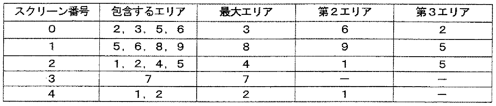
[0254] この表 1に基づいて、キー番号に対するスクリーン番号を割当てる。最大エリア MA 、第 2エリア A2、第 3エリア A3の順に空いているキー番号にスクリーン番号を割当て る。なお、第 nで既に割当てられた場合は、第 n+ 1では割当てられないものとする。 第 1の割当てで、 1つのエリアに複数のスクリーンがある場合、そのまま割当てる。第 2 の割当て、第 3の割当てでは、面積的にエリア内の占有率の大きい方に割当てるもの とする。ただし、占有率の差力 、さい場合は、双方に割当てるものとする。 [0254] Based on Table 1, the screen number is assigned to the key number. A screen number is assigned to the vacant key numbers in the order of maximum area MA, second area A2, and third area A3. Note that if it is already assigned at the nth, it is not assigned at the (n + 1) th. In the first assignment, if there are multiple screens in one area, assign them as they are. In the 2nd allocation and the 3rd allocation, allocation is to the area with the larger occupation ratio in the area. And However, in the case of the difference in occupation rate, in the case of allocation, both shall be assigned.
[0255] 前記表 1の最大エリアとスクリーン番号に基づいて、キー番号に対する第 1の割当 てを埋める。スクリーン SOに対する最大エリア MAはエリア A3である。このため、キー 番号 3に対して、第 1の割当てにスクリーン SOを埋める。割り振りのないキ一番に対す る第 1の割当てはそのままにし、第 2の割当てについて埋める。前記表の第 2エリア A 2とスクリーン番号に基づき、キー番号の内、第 1の割当てがないキー番号について、 第 2エリア A2に該当するスクリーン番号を記入する。スクリーン S2、 S4が第 2エリア A 2としてエリア A1となっている。この際、エリア A1において、面積の占有率の高い方 であるスクリーン S2を選択し、第 2の割当てとして記入する。同様に第 3の割当てにつ いても同様に行う。 [0255] Based on the maximum area and screen number in Table 1 above, the first assignment for the key number is filled. The largest area MA for screen SO is area A3. Therefore, the screen SO is filled in the first assignment for the key number 3. Leave the first assignment for the unallocated key and fill in the second assignment. Based on the second area A2 and the screen number in the table, enter the screen number corresponding to the second area A2 for the key numbers that do not have the first assignment among the key numbers. Screens S2 and S4 are area A1 as second area A2. At this time, in area A1, screen S2, which has the higher area occupancy, is selected and entered as the second assignment. Similarly, for the third assignment.
上記、画面のスクリーンの場合、下記の表 2の通りに割当てを割り振ることが可能とな る(キー番号一割当て)。 In the case of the above screen, assignment can be assigned as shown in Table 2 below (one key number assignment).
これにより、容易にスクリーンを選択することが可能となる。 This makes it possible to easily select a screen.
[0256] [表 2] [0256] [Table 2]
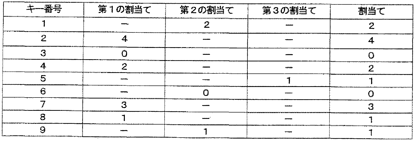
[0257] さらに、図 63に示すように、選択操作時に各々のスクリーン上に対応するキー番号 を表記することにより、より操作性を向上することが可能となる。 Furthermore, as shown in FIG. 63, the operability can be further improved by indicating the corresponding key number on each screen during the selection operation.
[0258] 図 64および図 65は、第 1のケースの場合の受信した音声の音量 (V )と表示倍 receive 率算出用の音量 (V )の関係を示す図である。 FIG. 64 and FIG. 65 are diagrams showing the relationship between the volume (V) of the received voice and the volume (V) for display double reception rate calculation in the case of the first case.
aispiay aispiay
図 66および図 67は、第 2のケースの場合の受信した音声の音量 (V ) receiveと表示倍 率算出用の音量 (V )の関係を示す図である。 FIG. 66 and FIG. 67 are diagrams showing the relationship between the received sound volume (V) receive and the display magnification calculation volume (V) in the second case.
display display
図において、直線は受信した音声の音量 (V . )、破線は表示倍率算出用の音量 (V )を示して 、る。横軸は時間軸、縦軸は音量を現して 、る。なお、 T は話し display speak ている時間、 T は話していない時間である。音量にはいくつかの閾値 V を設 silent level0,l,2 定する。 In the figure, the straight line is the volume of the received voice (V.), and the broken line is the volume for calculating the display magnification. Show (V). The horizontal axis represents the time axis, and the vertical axis represents the volume. T is the time when the display is spoken, and T is the time when it is not speaking. Set several thresholds V for volume, silent level 0, l, 2.
[0259] 図 64および図 65のケース 1は、「あいづち」などの短い音声の場合を示し、ケース 2 は、会話中などの長い音声の場合を示している。 Case 1 in FIG. 64 and FIG. 65 shows the case of a short voice such as “Aizuchi”, and case 2 shows the case of a long voice such as during a conversation.
ケース 1の場合において、時間 tにて、「はい」と音声があり、受信音量 (V )が閾 In case 1, at time t, “Yes” is heard and the reception volume (V) is the threshold.
1 receive 値 (V )を越え、 Vとなった場合、音声入力に大きな変化があつたと判断し、表示 levelj 2 1 When the receive value (V) is exceeded and becomes V, it is determined that there is a large change in the audio input, and the display levelj 2
倍率算出用の音量 (V )は、直値 (V )を取る。期間 [t ,t ]では、閾値 (V )をま display 2 1 2 levelj たがない。このとき、この期間 [t ,t ]では、表示倍率用の音量 (V )は、この期間に The volume (V) for magnification calculation takes a direct value (V). In the period [t, t], the threshold (V) is not displayed. At this time, during this period [t, t], the volume (V) for display magnification is
1 2 display 1 2 display
おける受信音量 (V )の平均値を取る。 Take the average value of reception volume (V).
receive receive
受信音量 (V )が下限閾値 (V )をまたいだ場合、音声の終了と判断し、表示 receive level3 If the reception volume (V) crosses the lower threshold (V), it is judged that the audio has ended and the display receive level3
倍率用の音量 (V )を減衰する。このとき、またいだ閾値 (V )を下限とする音量 display level3 Attenuate the volume (V) for magnification. At this time, the volume with the lower threshold (V) as the lower limit display level3
レベル ([V , V )の期間 (T )に依存して、減衰する速度を決定する。 Depending on the period (T) of the level ([V, V), the rate of decay is determined.
level3 ievel4 speak level3 ievel4 speak
発声期間 (τ ) Speech period (τ)
speakが短い場合、減衰を遅くし、発声期間(speaK)が長い場合、減衰を 早くする。ケース 1では、期間 (T ) When speak is short, the decay is slowed down, and when speaking period is long (speaK), the decay is accelerated. In case 1, period (T)
speakが短いので、減衰する速度を遅くする。静音期 間 (T )において、受信音量 (V )は Vと音量が小さくなつている。これに対して silent 1 receive 1 Since speak is short, slow down the decay rate. During the silent period (T), the reception volume (V) is V and the volume is decreasing. On the other hand, silent 1 receive 1
、表示倍率算出用の音量 (V )は、時間 t直前であっても、 V と比較的高い値 display 3 level2 The volume (V) for display magnification calculation is a relatively high value with V even immediately before time t display 3 level2
になっている。時間 tにて、「はい」と音声があり、受信音量 (V )が閾値 (V )を It has become. At time t, there is a sound “Yes”, and the reception volume (V) reaches the threshold (V).
3 receive level3 越えたため、先と同様に、音声入力に大きな変化があつたと判断し、表示倍率算出 用の音量 (V )は、直値 (V )を取る。 3 Receive level3 has been exceeded, so it is determined that there has been a significant change in the audio input as before, and the volume (V) for display magnification calculation takes the direct value (V).
display 2 display 2
[0260] 図 66および図 67のケース 2の場合にお!、て、時間 tにて、「今日は · · ·」と音声があ り、ケース 1と同様に、受信音量 (V )が閾値 (V )を越え、 Vとなったため、音 receive level 1,2, 3 2 [0260] In case 2 of Fig. 66 and Fig. 67, at time t, there is a voice saying "Today is ..." and, as in case 1, the reception volume (V) is the threshold value. (V) exceeds V and becomes V, so the sound receive level 1,2, 3 2
声入力に大きな変化があつたと判断し、表示倍率算出用の音量 (V )は、直値 (V display It is determined that there has been a significant change in voice input, and the volume (V) for calculating the display magnification is the direct value (V display
)を取る。閾値 )をまたがない期間 [t , t ]では、表示倍率用の音量 (V )は )I take the. In the period [t, t] that does not cross the threshold value), the volume (V) for display magnification is
2 levelj 1 2 display2 levelj 1 2 display
、この期間における受信音量の平均値 (mean (V ;) )を取る。時間 t2で、受信音量 receive Then, the average value (me an (V;)) of the reception volume during this period is taken. Receive volume at time t2 receive
(V )が下限閾値 (V )をまたいだ場合、音声の終了と判断し、発声期間 (T ) receive level3 speak に依存して、減衰速度を決定する。ケース 2では、発声期間 (T )が長いため、減 speak When (V) crosses the lower threshold (V), it is determined that the voice has ended, and the decay rate is determined depending on the utterance period (T) receive level3 speak. In case 2, the utterance period (T) is long, so decrease
衰を早くする。 「あいづち」「へんじ」などの短い音声に対して、発声の終了に対して、スクリーンの 変動をゆるやかに縮小するようにすることにより、スクリーンのサイズ変動における、視 覚上支障を低減することが可能となる。 Make the decline quicker. To reduce the visual hindrance in screen size fluctuations by reducing the screen fluctuations gently at the end of utterance for short voices such as “Aizuchi” and “Shinji”. Is possible.
[0261] 図 68は、図 64〜図 67に関連付けた処理の流れを示す図である。 [0261] FIG. 68 is a diagram showing a flow of processing associated with FIGS.
[0262] この場合、 3つの状態(state 1、 state2、 state3)を有する。 [0262] In this case, there are three states (state 1, state 2, state 3).
状態 (statel)は立上り状態であり、上限の閾値 (V )をまたいで、受信音量が増 The state (statel) is a rising state, and the reception volume increases across the upper threshold (V).
levelj levelj
大した場合である。 This is the case.
状態 (state2)は立下り状態、および立下り期間であり、下限の閾値 (V )をまた State (state 2) is a falling state and a falling period, and also crosses the lower threshold (V).
levelj- 1 いで、受信音量が低減した場合、および、状態 (state2)にあって、表示倍率算出用 の音量 (V )が受信音量 (V )より大き 、期間の場合である。 levelj-1, when the reception volume is reduced, and when in the state (state 2), the volume (V) for calculating the display magnification is larger than the reception volume (V) and during the period.
display receive display receive
状態 (state3)は安定期間であり、立上り状態後、上下限の閾値 (V 、 V )をま State (state 3) is a stable period, and after the rising state, the upper and lower thresholds (V, V) are met.
levelj levelj- 1 たがない期間、および状態 (state2)で、表示倍率算出用の音量 (V )が受信音量 levelj levelj- 1 The volume (V) for calculating the display magnification is the reception volume in the period and state (state2)
display display
を下回った後の期間の場合である。 This is the case for the period after falling below.
各々の期間における表示倍率算出用の音量 (V )の算出式を下記に示す。なお The calculation formula of the volume (V) for calculating the display magnification in each period is shown below. In addition
display display
、各状態の状態遷移を図 68のフローチャートのステップ ST40〜ST65に示す。 The state transition of each state is shown in steps ST40 to ST65 in the flowchart of FIG.
[0263] [数 23] [0263] [Numerical 23]
'立上リ觀 (Vr«i(w (t) ^ν,^,^ν^,, (t-At)) C→state1) 'Rie Uegami (V r « i (w (t) ^ ν, ^, ^ ν ^ ,, (t-At)) C → state1)
V display = V r receive V display = V r receive
'立下リ機 (Vret(t¥, (t) <V wi ≤Vr,Ml„ (t-Δ t)) (→state2) 'Falling machine (V ret (t ¥ , (t) <V wi ≤V r , Ml „(t-Δ t)) (→ state2)
Vdisplay = Vlevel + (Vbase - V! l ) CXP(~a jTspeak - ^se )) V display = V level + ( V base- V ! L) CX P (~ a j T speak-^ se))
*立下リ期颶 (Vd p i (t-At) ≥VfKiiv, (t~At)) (state2-state2) * Falling period (V dpi (t-At) ≥V fKiiv , (t ~ At)) (state2- state2 )
^display = ^levelj-l + (Fbase ~~ ^levelj -l) QXP(~a " tpeak 一 ^base )) ^ display = ^ levelj-l + (Fbase ~~ ^ levelj -l) QX P (~ a "tpeak one ^ base))
*安^間 (statel→state3) * Ansama (statel → state3)
VisPiay : mean U ) V is P iay: mean U)
'安 闥 (V ' (t-At) <Vrwaitt Ct-At» Cstate2→state3)'Anhui (V' (t-At) <V rwaitt Ct-At »Cstate2 → state3)
Vdisplay = _ 醫 receive^)) V display = _ 醫 receive ^))
[0264] 各スクリーン毎に、発声期間、静音期間を計測し、過去の発声期間、静音期間のパ ターンに基づいて、減衰速度を変化させる。 [0264] The utterance period and silent period are measured for each screen, and the decay rate is changed based on the patterns of the past utterance period and silent period.
具体的には、長さに応じて複数の発声期間を観る。発声期間に対して、その後の 静音期間を計測し、各々の発声期間における静音期間の平均値を算出する。任意 の発声期間があった場合、その後の静音期間における表示倍率算出用の音量 (Vdi splay)の減衰式におけるパラメータ aに対して、平均の静音期間が短い場合、減衰速 度を遅くなるように、パラメータ aを小さくする。 Specifically, a plurality of utterance periods are watched according to the length. The subsequent silent period is measured for the utterance period, and the average value of the silent period in each utterance period is calculated. When there is an arbitrary utterance period, when the average silent period is short relative to the parameter a in the attenuation formula of the display magnification calculation volume (V display) during the subsequent silent period, the attenuation rate is slowed down. Decrease parameter a.
これにより、立て続けに話を続けていく人 (スクリーン)の場合、静音期間にて即座に 減衰せず、次の発声期間にあまり減衰せずに繋がるようにすることが可能となる。 As a result, for a person (screen) who keeps talking continuously, it is possible to connect without being attenuated immediately in the silent period and without being attenuated much in the next utterance period.
[0265] 以上説明したように、本第 6の実施形態によれば、送信元となるエンコード装置 20 は、送信元は、画面上、指示した位置にスクリーンが存在する場合、対応する指示情 報、スクリーン情報、音量情報を生成し、同通信中の相手に対して送出する機能を有 し、デコード装置 30Eは、マルチスクリーンを表示する機能を有し、スクリーン中心間 を結ぶ線分、基準形状の厚さ、音声の大きさに基づいて、スクリーンの表示倍率を算 出し、この表示倍率に基づいてスクリーンの移動、新規生成を制御することにより、画 面上に複数のスクリーンを最適に形成し、画面上の表示エリアの配置パターンを解 祈し安定ィ匕するパターンの配置交換を行う機能を有することから、スクリーンのサイズ[0265] As described above, according to the sixth embodiment, the encoding device 20 serving as a transmission source, when the transmission source has a screen at the designated position on the screen, corresponds to the corresponding instruction information. In addition, the decoding device 30E has a function to generate screen information and volume information and send it to the other party during the communication. The screen display magnification is calculated based on the line segment connecting the two, the thickness of the reference shape, and the volume of the sound, and the screen movement and new generation are controlled based on this display magnification. The size of the screen is optimized because it has the function of optimally forming the screen, praying for the layout pattern of the display area on the screen, and replacing the stable pattern layout.
1S 音量の大きさ、およびスクリーン数に応じて、適応的にサイズを変動させることが できる。 1S The size can be changed adaptively according to the volume of the volume and the number of screens.
また、スクリーンの動きが連続的になり、異なる形状であっても、最適なサイズに配 置することが可能となる利点がある。 In addition, there is an advantage that the movement of the screen is continuous, and it is possible to arrange the screen in an optimal size even if the shape is different.
また、局所安定状態を解消する。 Moreover, a local stable state is eliminated.
さらに、特定スクリーンに対して、優先的にサイズを大きく設定することが可能となる さらにまた、スクリーン選択するキー押下回数を低減することが可能となる。 また、受信音量の変化に対して、受信音量が大きく増大する場合、スクリーンの拡 大は即応する。発声終了後のスクリーンの縮小する速さは、発声期間の長さに反比 例する。新たな発声に対して、即応してスクリーンサイズが大きくなる一方で、「あいづ ち」「へんじ」などの短い発声に対して、サイズの縮小は緩やかに縮小するため、短期 的にスクリーンが拡大'縮小を起こす目障りなスクリーンのサイズ変動をなくすことが 可能となる。 Furthermore, it is possible to preferentially increase the size for a specific screen. Furthermore, it is possible to reduce the number of key presses for screen selection. In addition, when the reception volume increases greatly in response to changes in the reception volume, the expansion of the screen responds quickly. The speed at which the screen shrinks after utterance is inversely proportional to the length of the utterance period. While the screen size increases immediately in response to new utterances, the screen size increases in the short term because the size reduction gradually decreases for short utterances such as “Aizichi” and “Shinji”. 'It is possible to eliminate annoying screen size fluctuation that causes reduction.
[0266] <第 7実施形態 > [0266] <Seventh embodiment>
[0267] 図 69および図 70は、本発明の第 7の実施形態に係る携帯通信端末の構成例を示 す図であって、図 69はエンコード装置を示すブロック図であり、図 70はデコード装置 を示すブロック図である。 69 and 70 are diagrams showing a configuration example of the mobile communication terminal according to the seventh embodiment of the present invention. FIG. 69 is a block diagram showing an encoding device, and FIG. 70 is a decoding diagram. It is a block diagram which shows an apparatus.
[0268] 本第 7の実施形態に係る携帯通信端末 10Fにおけるエンコード装置 40Fの基本的 なブロック構成は、第 2の実施形態で説明した図 17の構成と同様の構成を有し、また 、デコード装置 50Fの基本的なブロック構成は、第 2の実施形態で説明した図 18や 図 32の構成と同様である。 [0268] The basic block configuration of the encoding device 40F in the mobile communication terminal 10F according to the seventh embodiment has the same configuration as the configuration of Fig. 17 described in the second embodiment, and the decoding is performed. The basic block configuration of the device 50F is the same as the configuration of FIG. 18 and FIG. 32 described in the second embodiment.
[0269] 本第 7の実施形態に係る携帯端末装置 10Fは、第 2の実施形態や第 3の実施形態 等における機能に加えて、通信情報として、同一端末からの別セッションは、同一端 末の下位情報として付加し、画像を表示する表示エリアサイズは、最も下位に位置す る情報にかかわる表示エリアを注目すべき表示エリアと判断し、対応する表示エリア に制御する機能を有する。 [0269] In addition to the functions in the second embodiment, the third embodiment, and the like, the mobile terminal device 10F according to the seventh embodiment has different sessions from the same terminal as the same end as communication information. The display area size that is added as the lower information at the end and displays an image has a function of determining the display area related to the information located at the lowest position as the display area to be noted and controlling to the corresponding display area.
[0270] 上述したように、送信側である撮影者力カメラをバーンなどして被写体を変える場合 、その被写体を受信側である相手に見せたいがためである。その際に、必ずしも撮影 者は話しているとは限らない。このため、バーンした後に、何力しら話さないといけな いことになる。たとえば、何を購入してくれば良いか選択してもらうために、画像を送つ て 、る場合、絶えず撮影者が話しをしつづけることはできな 、。 [0270] As described above, when the subject is changed by burning the photographer-powered camera on the transmission side, it is desired to show the subject to the other party on the reception side. At that time, the photographer is not necessarily speaking. For this reason, after burning, you have to talk about how much power you have. For example, if you send an image to choose what to buy, the photographer can't keep talking.
しかし、受信した画像自体はその間絶えず視認できる大きさのスクリーンである必要 がある。 However, the received image itself needs to be a screen that can be seen continuously during that time.
[0271] さらに、通話中に送ったファイルは、その会話中、注目するべきファイルであり、表 示、再生した内容は、視認できる大きさのスクリーンである必要がある。 [0271] Furthermore, the file sent during the call is the file to be noticed during the conversation, and the displayed and played back content must be a screen that can be visually recognized.
従来の接続において、 2者通話から 3者通話へ移行する場合、双方に接続する端 末力 双方と接続するメディアを変更し、メディアミキシングとして動作する。スクリーン 制御は、メディアミキシングを行う端末が行うことになる。 In a conventional connection, when switching from a two-party call to a three-party call, the terminal power connected to both parties changes the media connected to both parties, and operates as media mixing. Screen control is performed by a terminal that performs media mixing.
つまり、スクリーンを表示する端末では、制御できない。この場合に、ファイル (画像 That is, the terminal that displays the screen cannot be controlled. In this case, the file (image
、音声)の同期再生、 webアクセスを一緒に行うとした場合、それに合わせたメディア 変更を、その度に行う必要がある。 ) (Sound) synchronized playback and web access together, it is necessary to change the media accordingly.
[0272] そこで、本第 7の実施形態においては、ユーザが操作することなぐ音量の大きさや 表示すべき表示画像エリア (スクリーン)の数等の状況に応じて適応的に、最適に表 示画像エリア (スクリーン)のサイズ、位置を更新することができ、しかも表示画像エリ ァの再配置 (移動)が連続的になり、受信側では即座にその画像を大きく見せることが 可能となり、送信側、受信側にて同タイミングで再生することが可能な携帯通信端末 を実現している。 [0272] Therefore, in the seventh embodiment, the display image is adaptively and optimally adapted according to the situation such as the volume level that the user does not operate and the number of display image areas (screens) to be displayed. The size and position of the area (screen) can be updated, and the display image area can be rearranged (moved) continuously. The receiving side can immediately make the image appear larger. A mobile communication terminal that can be played back at the same timing on the receiving side is realized.
[0273] 図 69のエンコード装置 40Fは、マイクロフォン等からなる音声入力部 401、デジタ ルカメラ等の画像入力部 402、キー入力等が可能な操作部 403、音声入力部 401に より入力される音声データを符号ィ匕する音声符号ィ匕処理部 404、画像入力部 402か ら入力され所定エリアに切り出された画像データを符号化する画像符号化処理部 40 5、撮像画像に関連付けた天地情報に基づいて、撮像画像の天地を受信側の表示 部の画面 (端末画面)の天地と一致するように補正する天地補正部 406、撮像画像 から顔のエリアを検出、抽出する顔エリア検出部 407、顔エリア検出部 407にて検出 された顔エリアに基づいて使用するスクリーン (表示すべき表示画像エリア)を判別し スクリーン情報を生成するスクリーン判定部 408、スクリーン判定部 408の判定に基 づ 、て受信画像から該当するエリアを切り出す切り出し処理部 409、音声入力部 40 1による入力音量を計測し音量情報を生成する入力音量計測部 410、操作部 403の 入力情報に基づいて端末を制御する端末制御部 411、端末制御部 411の指示に基 づいて指示情報や天地情報、スクリーン情報、音量情報等を含む制御情報を生成す る制御情報生成部 412、画像 ·映像を記憶する記憶部 413、符号化された音声デー タおよび画像データ、制御情報、端末制御部 411の指示に基づいて記憶部 413から 読み出された画像'映像データを送信パケットとして生成する送信パケット生成部 41 4、およびネットワークと無線通信可能で生成された送信パケットをネットワークを介し て通信相手の端末やサーバに送信するネットワークインタフェース (IZF) 415を有 する。 [0273] The encoding device 40F in FIG. 69 includes an audio input unit 401 composed of a microphone, an image input unit 402 such as a digital camera, an operation unit 403 capable of key input, and audio data input by the audio input unit 401. A voice code key processing unit 404 for encoding the image data, and an image encoding processing unit 40 for encoding the image data input from the image input unit 402 and cut out to a predetermined area. 5. Based on the top and bottom information associated with the captured image, the top and bottom correction unit 406 corrects the top and bottom of the captured image to match the top and bottom of the display screen (terminal screen) on the receiving side. Face area detection unit 407 for detecting and extracting, screen determination unit 408 for generating screen information by determining a screen (display image area to be displayed) to be used based on the face area detected by the face area detection unit 407 Based on the determination of the determination unit 408, the input processing unit 409 that extracts the corresponding area from the received image, the input volume measurement unit 410 that measures the input volume by the voice input unit 401 and generates volume information, and the input of the operation unit 403 Control for generating terminal control unit 411 that controls the terminal based on information, control information including instruction information, top and bottom information, screen information, volume information, and the like based on an instruction from terminal control unit 411 Information generation unit 412, storage unit 413 for storing image / video, encoded audio data and image data, control information, image read out from storage unit 413 based on instructions of terminal control unit 411 And a network interface (IZF) 415 for transmitting a transmission packet generated so as to be wirelessly communicable with a network to a communication partner terminal or server via the network.
図 70のデコード装置 50Fは、ネットワークと無線通信可能で送信元力も送信された 音声データ、画像 (映像)データ、制御情報や指示情報、スクリーン情報、音量情報等 を含むパケットを受信するネットワークインタフェース (IZF) 501、キー入力等が可能 な操作部 502、ネットワークインタフェース 501で受信されたパケットを解析し、音声 データ、画像データ、送信元アドレス、制御情報 (天地情報や指示情報等)を抽出す る受信パケット解析部 503、受信パケット解析部 503により抽出された音声データを 復号する音声復号処理部 504、受信パケット解析部 503により抽出された映像デー タを復号する映像復号処理部 505、映像復号処理部 505により復号された映像デー タ、送信元アドレス、制御情報、スクリーン情報、サイズ情報、天地情報に基づいて表 示すべきスクリーン (表示ウィンドウ)のサイズや表示形態を制御する表示画像制御部 506F、音声復号処理部 504により復号された音声の音量を修正する音量修正部 50 7、音量修正部 507で修正された音量で発音するスピーカ等の音声出力部 508、表 示画像制御部 506によりサイズや表示形態が制御された画像を補正する画像補正 部 509、画像補正部 509を介した画像を表示する LCD等の表示部 (画像出力部) 5 10、および操作部 502からの入力情報に基づ 、て表示画像制御部 506に制御情報 (天地情報)を与える自端末制御部 511を有する。 The decoding device 50F in FIG. 70 is a network interface that receives packets including audio data, image (video) data, control information and instruction information, screen information, volume information, and the like that can be wirelessly communicated with the network and transmitted from the transmission source. (IZF) 501, operation unit 502 capable of key input, etc., packet received by network interface 501, analysis of voice data, image data, source address, control information (top and bottom information, instruction information, etc.) Reception packet analysis unit 503, audio decoding processing unit 504 that decodes the audio data extracted by reception packet analysis unit 503, video decoding processing unit 505 that decodes video data extracted by reception packet analysis unit 503, video decoding processing Based on the video data decoded by the unit 505, transmission source address, control information, screen information, size information, and top and bottom information The display image control unit 506F controls the size of the screen (display window) to be displayed and the display form, the volume correction unit 50 7 corrects the volume of the audio decoded by the audio decoding processing unit 504, and the volume correction unit 507 corrects the volume. Image correction that corrects the image whose size and display form are controlled by the audio output unit 508 and the display image control unit 506 Based on the input information from the display unit (image output unit) 5 10 and the operation unit 502 that displays an image via the unit 509 and the image correction unit 509, control information (top and bottom) is displayed. A terminal control unit 511 for providing information).
[0275] なお、エンコード装置 40Fとデコード装置 50Fは、操作部 403と 502、ネットワークィ ンタフ ース 415と 501、端末制御部 411と自端末制御部 511は共用することが可能 である。 Note that the encoding device 40F and the decoding device 50F can share the operation units 403 and 502, the network interface 415 and 501, the terminal control unit 411 and the own terminal control unit 511.
[0276] 以下に、本第 7の実施形態の特徴部分である表示画像制御部 506Fのより具体的 な構成および機能、並びにスクリーンの具体的な構成や表示形態例にっ 、て順を追 つて説明する。 [0276] In the following, a more specific configuration and function of the display image control unit 506F, which is a characteristic part of the seventh embodiment, and a specific configuration and display example of the screen will be described in order. explain.
[0277] 図 70の表示画像制御部 506Fは、受信パケット解析部 503により供給される制御 情報に基づいてスクリーン情報、サイズ情報、天地情報、および指示情報を抽出する 制御情報解析部 5061、スクリーン情報に基づいて映像復号処理部 505で復号され た映像に対してマスキングを行うマスキング処理部 5062、サイズ情報、スクリーン情 報に基づいて表示すべきスクリーン (表示画像エリア)の表示倍率を算出す表示倍率 算出判定部 5063、表示倍率算出判定部 5063で算出された表示倍率に従ってマス キング処理後の画像を縮小 ·拡大する縮小 ·拡大処理部 5064、表示倍率算出判定 部 5063で算出された表示倍率および天地情報に従って表示位置を算出する表示 位置算出部 5065、および表示位置算出部 5065にて得られた表示部 510上の位置 に縮小 ·拡大処理部 5064にて得られた画像をマッピングするマッピング処理部 506 6を有する。 Display image control unit 506F in FIG. 70 extracts screen information, size information, top and bottom information, and instruction information based on the control information supplied from received packet analysis unit 503. Control information analysis unit 5061, screen information Masking processing unit 5062 for masking the video decoded by the video decoding processing unit 505 based on the above, the display magnification for calculating the display magnification of the screen (display image area) to be displayed based on the size information and the screen information Calculation determination unit 5063, Display magnification calculation determination unit Reduces and enlarges the image after masking according to the display magnification calculated by 5063. Enlargement processing unit 5064, Display magnification calculation determination unit 5063 Display magnification and top and bottom calculated by 5063 Display position calculation unit 5065 that calculates the display position according to the information, and reduction / enlargement processing to the position on display unit 510 obtained by display position calculation unit 5065 A mapping processing unit 5066 for mapping the image obtained by the unit 5064 is provided.
[0278] 本実施形態の表示画像制御部 506Fは、 1つ以上のスクリーンが局所領域にて継 続的に動き続ける状態にある力否かを判定する振動状態判定機能を有する。 [0278] The display image control unit 506F of the present embodiment has a vibration state determination function for determining whether or not one or more screens are in a state of continuously moving in a local region.
この振動状態判定機能は、一定期間 (n)において、スクリーン個数の変動がなぐ 各スクリーンの音声の大きさの変動がなぐさらに、スクリーンの位置の変動があり、変 動が閾値 (PthreshO)以下であり、スクリーンの表示倍率の変動が閾値 (RthreshO)以下 である場合、振動状態にあると判定し、振動状態中、前記期間中の表示倍率の二乗 総和値 (R)が最も大きい状態の配置に固定する。 In this vibration state judgment function, there is no change in the number of screens in a certain period (n), there is no change in the sound volume of each screen, there is a change in the screen position, and the change is below the threshold (PthreshO). Yes, if the fluctuation of the screen display magnification is less than or equal to the threshold (RthreshO), it is determined that it is in a vibration state, and the vibration display is placed in a state where the sum of squares (R) of the display magnification during the period is the largest. Fix it.
[0279] また、本実施形態の表示画像制御部 506Fは、スクリーンの安定状態にある力否か を判定する安定状態判定機能を有する。 [0279] Also, the display image control unit 506F of the present embodiment determines whether or not the screen is in a stable state. Has a stable state determination function.
この安定状態判定機能は、一定期間 (m)において、スクリーン個数の変動がなぐ 各スクリーンの音声の大きさの変動がなぐさらに、スクリーンの位置の変動が閾値 (P threshl)以下であり、スクリーンの表示倍率の変動が閾値 (Rthreshl)以下である場合 、安定状態にあると判定する。 In this stable state determination function, there is no change in the number of screens in a certain period (m), and there is no change in the sound volume of each screen.Furthermore, the change in the screen position is less than the threshold (P threshl), and If the change in display magnification is less than or equal to the threshold (Rthreshl), it is determined that the state is stable.
また、安定状態判定機能は、一定期間において、スクリーン個数の変動がなぐ各 スクリーンの音声の大きさの変動がなぐさらに、スクリーンの位置の変動が閾値 (Pthr eshl)以下であり、スクリーンの表示倍率の二乗総和比が閾値 (Rthresh2)以下である 場合、局所安定状態にあると判定する。 In addition, the stable state judgment function has no fluctuation in the volume of the sound of each screen, and the fluctuation in the screen position is less than the threshold (Pthr eshl), and the screen display magnification. If the sum of squares of is less than or equal to the threshold (Rthresh2), it is determined that the local stable state exists.
[0280] また、本実施形態の表示画像制御部 506Fは、スクリーンの安定状態判定機能に て、安定と判断された場合に、スクリーンの位置配置の再配置を促す攪拌処理機能 を有する。 [0280] Furthermore, the display image control unit 506F of the present embodiment has a stirring processing function that prompts rearrangement of the screen position arrangement when the screen stable state determination function determines that the screen is stable.
この攪拌処置機能は、画面上に仮の中心を配し、各中心における表示倍率の内、 先に選択しておらず、最も小さい値を取得する位置を攪拌用のスクリーンの中心とし 、一定期間、攪拌用のスクリーンを生成、更新し、消滅することによって、攪拌を行う。 攪拌処理の実行回数 (S)が閾値 (Sthresh)を越える場合、安定状態にあると判断し、 攪拌処理を停止する。 This agitation treatment function places a temporary center on the screen, and the display magnification at each center is not selected first, and the position where the smallest value is obtained is the center of the screen for agitation for a certain period of time. Stirring is performed by creating, updating and extinguishing the screen for stirring. When the number of executions (S) of the stirring process exceeds the threshold (Sthresh), it is determined that the state is stable and the stirring process is stopped.
[0281] 本第 7の実施形態の表示画像制御部 306Fによりサイズおよび表示形態が制御さ れるスクリーンは、 1つの画面上に複数のスクリーンを表示するマルチスクリーンとして 表示される。 [0281] The screen whose size and display form are controlled by the display image control unit 306F of the seventh embodiment is displayed as a multi-screen that displays a plurality of screens on one screen.
本第 7の実施形態の表示画像制御部 506Fの表示倍率算出判定部 5063、表示位 置算出部 5065の処理を中心としてマルチスクリーンの表示制御については、第 2の 実施形態において、図 19〜図 26等に関連付けて説明した表示制御と同様であるこ とから、ここではその説明を省略する。 With respect to the multi-screen display control centering on the processing of the display magnification calculation determination unit 5063 and the display position calculation unit 5065 of the display image control unit 506F of the seventh embodiment, FIG. 19 to FIG. Since this is the same as the display control described in relation to 26 etc., the description thereof is omitted here.
[0282] 次に、前述した実施形態と重複する部分はあるが、本第 7の実施形態における表示 形態例について説明する。 [0282] Next, although there are portions that overlap the above-described embodiment, an example of a display form in the seventh embodiment will be described.
[0283] 図 71に示すように、顔エリアの面積が一定値以上の場合、受信画像を「人物画像」 と判別する。顔エリアの面積が一定値以下の場合、受信画像を「非人物画像」と判別 する。 As shown in FIG. 71, when the area of the face area is greater than or equal to a certain value, the received image is determined as a “person image”. When the area of the face area is below a certain value, the received image is identified as a “non-human image” To do.
「人物画像」と判別した場合、円形スクリーンとする。「非人物画像」と判別した場合 、四角形スクリーンとする。「非人物画像」であっても、同送信元力もの音圧に応じて、 表示サイズを変動させる。 When it is determined that the image is a “person image”, a circular screen is used. If it is determined that the image is a “non-human image”, the screen is a quadrilateral screen. Even for non-human images, the display size is changed according to the sound pressure of the same transmission source.
[0284] 図 72に示すように、顔として判定されたエリアが複数ある場合であって、個数が一 定値以下の場合、面積の大きいほうを優先し、個数が一定値以上の場合、非人物と 同様、四角形スクリーンで表示する。 [0284] As shown in FIG. 72, when there are a plurality of areas determined as faces, when the number is less than a certain value, priority is given to the larger area, and when the number is more than a certain value, As with, display on a square screen.
[0285] 図 73に示すように、切り出しエリアが、受信画像から、顔が出て行った場合 (はみ出 し場合)、動きベクトル力 切り出し可能なエリアを推定し、円形スクリーン (ウィンドウ)を 見えている部分だけにする。 [0285] As shown in FIG. 73, when the cutout area is a face that protrudes from the received image (when protruding), the motion vector force is estimated and the circular screen (window) can be seen. Only the part that is.
推定された顔エリアのサイズに対する画面上に残っている顔画像の比が一定値以 下になつた場合、その顔を対象外とする。 If the ratio of the face image remaining on the screen to the estimated face area size falls below a certain value, that face is excluded.
[0286] 次に、以上の機能を有する携帯通信端末 10Fを用いた多地点通信処理について 説明する。 [0286] Next, multipoint communication processing using the mobile communication terminal 10F having the above functions will be described.
[0287] 本第 7の実施形態においては、通信情報として、同一端末からの別セッションは、 同一端末の下位情報として付加し、スクリーンサイズは、最も下位に位置する (最後 に付加した)情報にかかわるスクリーンを注目すべきスクリーンと判断し、対応するスク リーンサイズにする。他のスクリーンは最小にする。 [0287] In the seventh embodiment, as communication information, another session from the same terminal is added as lower information of the same terminal, and the screen size is the lowest position (added last) information. The screen concerned is judged as the screen to be noted and the corresponding screen size is set. Minimize other screens.
ファイル表示、再生に関して、送信側にて、同期再生を要求した場合、同ファイルを 転送するとともに、再生開始時間の情報を送出し、送信側、受信側では、前記再生 開始時間に従って、前記ファイルを再生する。 For file display and playback, when the transmission side requests synchronous playback, the same file is transferred and information on the playback start time is sent, and the transmission side and the reception side send the file according to the playback start time. Reproduce.
通話時に、カメラを起動(などの操作)に基づいて、カメラによる撮像画像のストリー ミング送信の有無を表示し、操作者が許可した場合、現在通話している相手に、ストリ 一ミングの再生要求を送出し、受信側が再生を許可した場合に、これに基づいて、ス トリーミング配信を開始し、受信側では新たなスクリーンを生成し、受信ストリーミング を再生する。 When a call is made, the camera is activated (such as operation) to display whether or not the camera sends an image stream. If the operator permits it, a streaming playback request is sent to the other party who is currently talking. When the receiving side permits playback, streaming distribution starts based on this, and the receiving side generates a new screen and plays the received streaming.
また、通話時に、カメラにて静止画像を撮影した場合、静止画像の送信有無を表示 し、操作者が許可した場合、現在通話している相手に、画像の再生要求を送出し、 受信側が再生を許可した場合に、これに基づいて、画像を送出し、受信側では、新 たなスクリーンを生成し、受信画像を再生する。 In addition, when a still image is taken with the camera during a call, the presence / absence of transmission of the still image is displayed, and if the operator permits, an image playback request is sent to the other party who is currently talking, When playback is permitted by the receiving side, an image is transmitted based on this, and the receiving side generates a new screen and plays back the received image.
送信側にて、再生スクリーンを閉じた場合、その旨を受信側に送出し、閉じたスクリ ーンに対応する情報を再生しているスクリーンを閉じ、対応する情報を削除する。 If the playback screen is closed on the sending side, this is sent to the receiving side, the screen playing back the information corresponding to the closed screen is closed, and the corresponding information is deleted.
[0288] 端末数 (人数 N (N≥ 1) )と同時通話して!/、る第 1のグループと、端末数 (人数 M (M ≥ 1) )と同時通話して 、る第 2のグループと、双方と通話接続して!/、る端末にお 、て 、双方のグループを 1つのグループとする場合、一方のグループに、発呼元情報(電 話番号、 IPアドレス、 MACアドレス、その他端末を識別可能な識別子 etc)と、認証キ 一、暗号キーから構成される着呼要求と送出し、他方のグループに、送信先情報 (電 話番号、 IPアドレス、 MACアドレス、その他端末を識別可能な識別子 etc)と、認証キ 一、暗号キーから構成される発呼要求を送出し、発呼要求を受信した端末は、前記 発呼要求に記載の情報に基づいて、発呼し、着呼要求を受信した端末は、着呼が、 前記着呼要求に記載の情報 (発呼元情報、認証キー、暗号キー)と一致するかを判 定し、一致する場合、接続を行う。 [0288] Talking simultaneously with the number of terminals (number of people N (N ≥ 1))! /, The second group talking simultaneously with the first group and the number of terminals (number of people M (M ≥ 1)) When a group and a terminal that is connected to both parties! /, Make both groups one group, caller information (phone number, IP address, MAC address, An incoming call request consisting of an identifier etc. that can identify other terminals, an authentication key, and an encryption key is sent, and destination information (telephone number, IP address, MAC address, other terminals) is sent to the other group. A terminal that sends a call request composed of an identifiable identifier etc), an authentication key, and an encryption key, and receives the call request, makes a call based on the information described in the call request, The terminal that has received the incoming call request receives the incoming call with the information (calling source information, authentication key, encryption key) described in the incoming call request. If it matches, connect.
[0289] また、画面上において、同じ同時通話のグループに所属するスクリーンは、スクリー ン外枠の色、太さを同色にする。 [0289] On the screen, screens belonging to the same simultaneous call group have the same color and thickness for the outer frame of the screen.
着信があった場合、着信相手の番号に対応する画像をメモリから読み出し、新たに スクリーン上に生成し、前記スクリーンは、外枠の色を着信用に振り分けた色にし、外 枠を大小振幅し、また色が濃淡変動させる(ないし点滅)。 When an incoming call is received, an image corresponding to the number of the called party is read from the memory and newly generated on the screen. The screen changes the color of the outer frame for incoming calls, and the outer frame has a large and small amplitude. In addition, the color is varied (or flashing).
自端末のカメラにて撮像した画像を表示するスクリーンのサイズは、自端末のマイク にて入力された音声に依存せず、一定の大きさとし、他のスクリーンの挙動演算に対 しては、前記スクリーンの外枠は、画面の外枠における壁と同等の扱いとする。 The size of the screen that displays the image captured by the camera of its own terminal does not depend on the sound input by the microphone of its own terminal, and is set to a certain size. The outer frame of the screen is handled in the same way as the wall in the outer frame of the screen.
[0290] また、自端末のマイクロフォンにて取得した音声を送出しているスクリーンの外枠の 色を濃くし、音声を送出していないスクリーンの外枠の色を薄くする(また、太さを変 化させる)。 [0290] Also, darken the color of the outer frame of the screen that is transmitting the sound acquired by the microphone of its own terminal, and lighten the color of the outer frame of the screen that is not transmitting sound (and reduce the thickness). Change).
前時刻の受信側のスクリーンサイズに基づ ヽて、送信画像の符号化率を制御する。 また、同一画像を受信再生する受信側のスクリーンサイズに応じて、画面に対して の占有率が最も大きいサイズに合わせて符号ィ匕し、全部 (Iピクチャ、 Pピクチャ、 Bピ クチャ)を送出し、これより小さいサイズに対しては、符号化データから、 Bピクチャを 除いた Iピクチャ、 Pピクチャを送出する。 Based on the screen size on the receiving side at the previous time, the coding rate of the transmitted image is controlled. Also, according to the screen size of the receiving side that receives and plays back the same image, it signs according to the size with the largest occupancy ratio on the screen, and all (I picture, P picture, B picture) For smaller sizes, send I-pictures and P-pictures excluding B-pictures from the encoded data.
さらに、小さいサイズに対しては、符号化データから、 Pピクチャ、 Bピクチャを除い た Iピクチャのみを送出し、さらに小さいサイズに対しては、符号化データから、 Pピク チヤ、 Bピクチャを除き、 Iピクチャを間引いたデータを送出する。 Furthermore, for small sizes, only I pictures excluding P and B pictures are sent from the encoded data, and for smaller sizes, P pictures and B pictures are excluded from the encoded data. , Send out data with I picture thinned out.
[0291] また、スクリーンサイズ力 アップサンプリングにて、視覚的に不快感を与えるノイズ を生成しない範囲(たとえば面積比 2倍以下)の場合、同一のサイズとして取り扱う。 スクリーンサイズの変動に伴う、符号化サイズの変動は、 Iピクチャ単位で取り扱う。 スクリーンサイズの変動に伴い、符号化サイズの変動は、予測画像を現在のサイズ にアップサンプリング (ないしはダウンサンプリング)し、フレーム間予測を行い、受信 側では、同様に予測画像をアップサンプリング (ないしはダウンサンプリング)し、復号 する。 [0291] In addition, if the screen size is within a range that does not generate visually unpleasant noise (for example, an area ratio of 2 times or less), it is handled as the same size. Coding size variation due to screen size variation is handled in I picture units. As the screen size fluctuates, the coding size fluctuates by up-sampling (or down-sampling) the predicted image to the current size and performing inter-frame prediction. On the receiving side, the predicted image is similarly up-sampled (or down-sampled). Sampling) and decoding.
[0292] 以上の機能を有する携帯通信端末 10Fを用いた多地点通信処理について、図 74 [0292] FIG. 74 shows multipoint communication processing using the mobile communication terminal 10F having the above functions.
〜図 78に関連つけて具体的に説明する。 ~ This will be described in detail with reference to FIG.
[0293] 図 74は、本実施形態に係る基本的な通信処理例を示す図である(S101〜S108) FIG. 74 is a diagram showing an example of basic communication processing according to the present embodiment (S101 to S108).
[0294] 本実施形態においては、前述したように、通信情報として、同一の端末からの別セ ッシヨンは、同一端末の下位情報として付随する。最も下位に位置する (最後に付カロ した)情報にかかわるスクリーンのサイズを、注目すべきスクリーンとして制御し、他の スクリーンは最小のサイズにする。 [0294] In this embodiment, as described above, another session from the same terminal is attached as lower information of the same terminal as communication information. The size of the screen related to the lowest-level information (the last one added) is controlled as a noticeable screen, and the other screens are set to the minimum size.
ファイル再生に関しては、送信側にて、(同期)再生を要求した場合、同ファイルを 転送するとともに、再生タイミングを同期化させるために、データ再生可能なデータ容 量を送信した際に、再生開始時間の情報を送出し、送信側、受信側では、前記再生 開始時間に従って、再生を開始する。 For file playback, if (synchronous) playback is requested on the transmission side, the file is transferred and playback is started when data capacity that can be played back is transmitted to synchronize the playback timing. Time information is transmitted, and playback is started on the transmission side and reception side according to the playback start time.
送信側にて、再生スクリーンを閉じた場合、受信側においても、再生スクリーンを閉 じる。通信情報として確保していたメモリを開放する。 When the playback screen is closed on the transmitting side, the playback screen is also closed on the receiving side. Release the memory reserved for communication information.
送信側、受信側にて、再生を停止した場合、その旨の情報を、同様に再生スクリー ンを立ち上げている他の端末に送出し、前記情報を受信した端末では、再生スクリー ン上に停止した旨を表示の上、再生を停止する。 When playback is stopped on the transmitting side and the receiving side, information to that effect is sent to the other terminals that have also started up the playback screen, and the terminal that received the information receives the playback screen. Stops playback after displaying that it has stopped on the screen.
通話開始時においては、音声通話 (VoIP)を基本とし、端末の操作に基づき、カメラ 力 撮像された映像を別のセッションとして送出する。 At the beginning of the call, voice call (VoIP) is basically used, and the camera-captured video is sent out as a separate session based on the operation of the terminal.
電話番号、ないしアドレス (通話相手の特定する識別子)に付随して、起動時に同 時にカメラの起動、および撮像映像送信用のセッションを張る力否かの情報を蓄積し 、前記情報に基づいて、通話時の映像送信の処理を行う。 Accompanying the telephone number or address (identifier that identifies the other party), information on whether or not the camera is activated at the time of activation and whether or not it is capable of establishing a session for transmitting captured video is stored. Based on the information, Performs video transmission processing during a call.
ファイルが音楽などのファイルの場合、再生用のアプリケーションをスクリーン内に 表示する。スクリーンサイズは、音量に依存しない。 If the file is a file such as music, a playback application is displayed on the screen. The screen size does not depend on the volume.
[0295] 図 75は、 webサイトを開いている際の通信処理例を示す図である(S 111〜S 118) FIG. 75 is a diagram showing an example of communication processing when a website is opened (S 111 to S 118)
[0296] webサイトを開いている際に、共有 (ないし、送信)を選択した場合、 webサイトのアド レスを送出する。 [0296] When sharing (or sending) is selected while the website is open, the website address is sent out.
受信側では、 webサイトを受信すると、 webサイトアクセス用の情報を同一セッション の付属情報として連結し、新しいスクリーン上にて、アクセスした webサイトを表示する 。最後に付属した情報である場合、 webサイトの表示用のスクリーンのサイズを音声比 に対応させた大きさに設定する。他のスクリーンは最小のサイズにする。 When the receiving side receives the website, it links the information for accessing the website as the attached information of the same session, and displays the accessed website on a new screen. In the case of the information attached at the end, the size of the screen for displaying the website is set to a size corresponding to the audio ratio. Other screens should be the smallest size.
音ファイルを送信とした場合、音ファイルと、再生タイミングを送出し、送信側、受信 側にて、前記再生タイミングに合わせて、音ファイルを再生する(同期再生を要求して いる場合)。 When a sound file is transmitted, the sound file and playback timing are transmitted, and the sound file is played back at the transmission side and the reception side in accordance with the playback timing (when synchronous playback is requested).
受信側では、音ファイルに対して、表示する画像、情報などの付属情報がない場合 、再生用のソフトを操作可能なサイズにて、新たなスクリーン上に表示する。他のスク リーンは最小のサイズにする。 On the receiving side, if there is no attached information such as images and information to be displayed for the sound file, the playback software is displayed on a new screen in a size that allows the playback software to be operated. Other screens should be the smallest size.
[0297] 図 76は、 webサイトのアドレス送出に対して、受信側が拒否をした場合の通信処理 例を示す図である(S121〜S125)。 [0297] FIG. 76 is a diagram showing an example of communication processing in the case where the receiving side refuses to send a website address (S121 to S125).
[0298] webサイトのアドレス送出に対して、受信側が拒否をした場合に、送信側は、現在表 示中の webサイトを画像保存し、再度、画像としての送信を試みる。 [0298] If the recipient refuses to send the website address, the sender saves the image of the currently displayed website and tries to send it as an image again.
受信側にて、画像受信を許可した場合に、画像が送出され、受信側にて、新たなス クリーン上に画像を再生される。 [0299] なお、以上、画像ファイル、音声ファイル、 webサイトなどの送出、受信に関しては、 先に再生要求にて、送信元のアドレスと、それに伴う接続ポートの確認、および認証 キー、暗号ィ匕キーなどの交換などを行っておくことにより、関係ない端末力も送出され てきたファイル (ストリーミングなどを含む)、 webサイトの再生を行うことを排除する。 これにより、関係端末からの不特定多数への広告、勧誘などの情報配信を排除す ることが可能となる。また、音声通話している相手であっても、送信要求に対して、拒 否を行うことを可能とすることにより、不要と推測される情報の受信を防ぐことが可能と なる。 When the receiving side permits image reception, the image is sent out, and the receiving side reproduces the image on a new screen. [0299] As for the sending and receiving of image files, audio files, websites, etc., the sender's address and the connection port that accompanies it, and the authentication key, encryption key, etc. By exchanging keys, etc., it eliminates the reproduction of files (including streaming etc.) and websites that have been sent with unrelated terminal capabilities. This makes it possible to eliminate the distribution of information such as advertisements and solicitations to unspecified majority from related terminals. In addition, even if the other party is making a voice call, it is possible to prevent the reception of information that is estimated to be unnecessary by allowing the transmission request to be rejected.
なお、送信側、受信側にて、選択的にスクリーンを選択することにより、スクリーンサ ィズをコントロールすることも可能となる。 It is also possible to control the screen size by selectively selecting a screen on the transmission side and the reception side.
[0300] 図 77は、通信処理時のスクリーンの表示形態例を示す図である。 [0300] Fig. 77 is a diagram showing an example of a display form of the screen at the time of communication processing.
[0301] スクリーンの外枠は、一緒に通話をしているグループに所属するスクリーンは、同一 の色とする。 [0301] The outer frame of the screen is the same color for the screens belonging to the group that is talking together.
異なるグループの場合、スクリーンの外枠は、基本的には異なる色とする。 音声を送っていないグループの場合、そのグループに所属するスクリーンの外枠は For different groups, the outer frame of the screen is basically a different color. For groups that are not sending audio, the outer frame of the screen that belongs to that group
、音声を送信していないことが明示的に分力るように通常と異なる色 (たとえば淡色化 する)ないし太さにする。 Use a different color (for example, lighter) or thickness so that audio is not being transmitted.
また、スクリーン内の画像が淡色化、霧が力かったような画像など、変化させる。 着信があった場合には、着信が明示的に分かるように、スクリーンを変化させる。た とえば、スクリーンのサイズを大きぐ小さく振動、外枠の色を点滅させる。 In addition, the image on the screen is changed to a lighter color or an image in which fog is strong. If there is an incoming call, the screen is changed so that the incoming call is clearly identified. For example, the screen size is increased by small vibrations and the color of the outer frame blinks.
第 3者の通話への参カ卩は、双方と通信を行っている端末力 操作を行う。既存のグ ループに対して、着呼要求 (発呼元を識別する識別子、認証キー)を送出するととも に、新規に参加する端末に対して、発呼要求 (発呼先を識別する識別子、認証キー) を送出する。 When a third party participates in a call, the terminal is operated to communicate with both parties. An incoming call request (an identifier for identifying a caller, an authentication key) is sent to an existing group, and a call request (an identifier for identifying a callee, (Authentication key).
新規に参加する端末は、前記発呼要求に従って、記載された発呼先に発呼する。 既存の端末は、前記新規の端末からの発呼に対して、着呼動作を行い、認証キーが 一致している場合、接続する。 The newly joining terminal calls the described call destination according to the call request. The existing terminal performs an incoming call operation for a call from the new terminal, and connects when the authentication keys match.
認証キーが異なる場合、即座に切断する。接続が完了した場合、接続を促した端 末は、新規参加端末力もの接続完了の情報に基づいて、新規端末を参加完了と判 断する。なお、既存端末においては、前記着呼動作における認証キーに基づいて、 同グループへの参加完了とする。 If the authentication key is different, disconnect immediately. When connection is complete, the end that prompted the connection At the end, the new terminal is judged to have completed participation based on the connection completion information of the new participating terminal. In the existing terminal, participation in the group is completed based on the authentication key in the incoming call operation.
自端末のカメラにて撮像した画像を画面上に表示する場合、スクリーンのサイズは 、音声に依存せずに、一定の大きさとする。なお、自端末の映像であることが明示的 に分力るように、スクリーンの外枠の色、太さを設定する。また、他のスクリーンのサイ ズ演算においては、自スクリーンの外枠を壁と同様の扱いにする。 When an image captured by the camera of its own terminal is displayed on the screen, the screen size is set to a constant size without depending on the sound. Note that the color and thickness of the outer frame of the screen are set so that the video of the terminal is clearly divided. In other screen size calculations, the outer frame of the screen is handled in the same way as the wall.
[0302] なお、図 77において、端末 10— 1側のステップ ST71では、ユーザ UBに音声を送 信する。ただし、 UBからは音声は送られてこない。 [0302] In FIG. 77, in step ST71 on the terminal 10-1 side, audio is transmitted to the user UB. However, no audio is sent from the UB.
ステップ ST72では、ユーザ UBに音声を送信する。この場合、 UBからは音声は送 られている。 In Step ST72, the voice is transmitted to the user UB. In this case, audio is sent from the UB.
ステップ ST73では、同じスクリーン枠色は同じする。この場合、ユーザ UB, UCに 音声を送信する。 In step ST73, the same screen frame color is the same. In this case, the voice is transmitted to the users UB and UC.
[0303] 端末 10— 2側のステップ ST81では、着信があった場合、電話帳から関連付けられ た画像を読み出し、スクリーンを生成する。スクリーンが点滅ないし、枠のサイズが大 小振動する。スクリーン枠色は、通話中のグループの色と異なる色を用いる。 [0303] In step ST81 on the terminal 10-2 side, when there is an incoming call, the associated image is read from the telephone directory and a screen is generated. The screen does not flash and the frame size vibrates. As the screen frame color, a color different from the color of the group in communication is used.
ステップ ST82では、音声を送出して ヽな 、通信相手のスクリーンの枠色を淡色化 し、スクリーン内の画像も輝度のゲインを強くする。この場合、ユーザ UAのみ音声を 送信する。 In step ST82, voice is transmitted and the frame color of the communication partner's screen is lightened, and the luminance gain of the image on the screen is also increased. In this case, only the user UA transmits audio.
ステップ ST83では、音声を送出して 、な 、通信相手のスクリーンの枠色を淡色化 し、スクリーン内の画像も輝度のゲインを強くする。この場合も、ユーザ UAのみ音声 を送信する。 In step ST83, sound is transmitted, the frame color of the communication partner's screen is lightened, and the luminance gain of the image on the screen is also increased. In this case, only the user UA transmits audio.
ステップ ST84では、同じグループのスクリーン枠色は同じにする。この場合、ユー ザ UB, UCに音声を送信する。 In step ST84, the same group of screen frame colors are used. In this case, audio is transmitted to user UB and UC.
[0304] 図 78は、前時間の受信側のスクリーンサイズ情報に基づ 、て、送信画像の符号化 率を制御する通信処理例を示す図である。 [0304] FIG. 78 is a diagram illustrating an example of communication processing for controlling the coding rate of the transmission image based on the screen size information on the reception side of the previous time.
[0305] 前時間の受信側のスクリーンサイズ情報に基づいて、送信画像の符号化率を制御 することにより、受信端末にて受信する符号量の合計が著しく大きくなることを防ぐ。 受信側のスクリーンサイズに応じて、 2つ以上にサイズに分類する。サイズの最も大 きいサイズに合わせて符号ィ匕する。小さいサイズに対しては、符号ィ匕データを間引い て送信する。 [0305] By controlling the coding rate of the transmission image based on the screen size information on the receiving side of the previous time, the total amount of codes received at the receiving terminal is prevented from becoming extremely large. Depending on the screen size of the receiver, classify it into two or more sizes. Sign according to the largest size. For small sizes, the code data is thinned and transmitted.
たとえば、サイズの最も大きさサイズに対しては、 Iピクチャ (フレーム内符号化)、 P ピクチャ (フレーム間順方向予測符号化)、 Bピクチャ (フレーム間双方向予測符号ィ匕 )全てを送出する。 For example, for the largest size, I picture (intra-frame coding), P picture (inter-frame forward prediction coding), and B picture (inter-frame bi-directional prediction code) are all sent. .
これに対して、 1つ下のサイズに対しては、 Bピクチャを間引ぐ更に小さいサイズに 対しては、 Bピクチャ、 Pピクチャを間引くことによって、送信する符号量を低減する。 また、符号化する画像のサイズに対しては、受信側のスクリーンの最大サイズに合わ せるのではなぐ最大サイズに対して、アップサンプリングすることによって、最大サイ ズのスクリーンにて視覚的に補間可能なサイズなサイズに抑える(たとえば、アップサ ンプリングを面積比 2倍以下に押さえることにより、アップサンプリングによるエイリアシ ングを低減することが可能である)。 On the other hand, for the smaller size, the code size to be transmitted is reduced by thinning out the B picture and P picture for the smaller size of thinning out the B picture. In addition, the size of the image to be encoded can be visually interpolated on the maximum size screen by upsampling the maximum size that does not fit the maximum size of the receiving screen. Keep the upsampling to a small size (for example, by suppressing upsampling to less than twice the area ratio, aliasing due to upsampling can be reduced).
[0306] 実際には、顔画像を送出する場合は、全撮像画像の内、顔のエリアのみを符号ィ匕 することにより、背景などの送信上、不要エリアを削減することにより、符号化効率を 上げることが可能となる。 [0306] In actuality, when transmitting a face image, only the face area of all captured images is encoded, thereby reducing unnecessary areas for transmission such as the background, thereby reducing the encoding efficiency. Can be raised.
換言すれば、符号ィ匕する画像において、顔が大きくなり、変化分の大きい背景が少 なくなることにより、符号量を増大させる高周波成分を低減させ、結果的に符号量を 低減することが可能となる。 In other words, in the image to be encoded, the face becomes large and the background with a large amount of change is reduced, so that it is possible to reduce the high-frequency component that increases the code amount and consequently reduce the code amount. Become.
結果的に送信側の符号化処理の負担を増大させることなぐ個々の端末に送出す る符号ィ匕データを生成することが可能であるとともに、個々の端末にて受信する符号 化データ容量の増大を抑え、ネットワークへの負荷の増大を低減することが可能とな る。 As a result, it is possible to generate code data to be sent to individual terminals without increasing the burden of encoding processing on the transmission side, and increase the amount of encoded data received at each terminal. It is possible to reduce the increase in the load on the network.
[0307] 図 78 (1)では、ユーザ端末 UAのユーザが一人話している状態であり、ユーザ端末 UB、 UCにおけるユーザ端末 U Aのスクリーンサイズは、同じ程度に大きい。 [0307] In Fig. 78 (1), the user of the user terminal UA is talking alone, and the screen size of the user terminal UA in the user terminals UB and UC is about the same.
このため、このサイズに合わせて、ユーザ端末 UAは符号化した画像を送出する。 これに対しては、ユーザ端末 UBのスクリーンは、ユーザ端末 U Aでは、中ぐらいの 大きいであるのに対して、ユーザ端末 UCでは、非常に小さい。このため、ユーザ端 末 UA用とユーザ端末 UC用の画像データとして送出する。ユーザ端末 UA用の方が 大きいため、これに合わせて符号ィ匕する。ユーザ端末 UCに対しては、 Iピクチャのみ (な 、しは、更に Iピクチャをも間引 、た)符号化データを送出する。 Therefore, the user terminal UA sends an encoded image in accordance with this size. On the other hand, the screen of the user terminal UB is moderately large at the user terminal UA, whereas it is very small at the user terminal UC. For this reason, the user end End Send out as image data for UA and user terminal UC. Since the user terminal UA is larger, code it accordingly. To the user terminal UC, encoded data is sent only for I pictures (or even I pictures are thinned out).
[0308] 図 78 (3)の場合、ユーザ端末 UB、 UCにおけるユーザ端末 U Aのスクリーンサイズ は、アップサンプリングして再生しても視覚的に(ノイズによる)不快感が発生しな 、と 判断した場合、小さ 、方のサイズに合わせて符号ィ匕データを送出する。 [0308] In the case of Fig. 78 (3), the screen size of the user terminal UA in the user terminals UB and UC is judged to be visually unpleasant even when upsampled and played back (due to noise). In this case, the code data is transmitted in accordance with the smaller size.
同様に、ユーザ端末 UA、 UBにおけるユーザ端末 UCのスクリーンサイズにおいて も、同様に、アップサンプリングして再生しても視覚的に(ノイズによる)不快感が発生 しな ヽと判断した場合、小さ ヽ方のサイズに合わせて符号化データを送出する。 Similarly, the screen size of the user terminal UC in the user terminals UA and UB is similarly small if it is judged that there is no visual discomfort (due to noise) even if upsampling and playback are performed. Encoded data is sent out according to the size of the other.
[0309] 再生スクリーンのサイズ力 差異がアップサンプリングにて吸収可能な範囲(ex.面 積比 2倍以内)である場合、同一のサイズとし、小さい方のスクリーンサイズに合わし て符号化処理を行う。 [0309] If the difference in size of the playback screen is within the range that can be absorbed by upsampling (ex. Area ratio is less than 2 times), the same size is used, and encoding is performed according to the smaller screen size. .
スクリーンサイズの変動に伴う符号ィ匕方式に対応して、 Iピクチャ(フレーム内符号ィ匕 )単位に、スクリーンサイズの変更を行う。 The screen size is changed in units of I picture (intra-frame code key) corresponding to the code key method that accompanies the change in screen size.
また、 Pピクチャ(フレーム間順方向予測符号化)でのスクリーンサイズの変動がある 場合、予測画像を現在のサイズ変更した画像に合わせてアップサンプリング、ないし ダウンサンプリングし、この間でフレーム間予測処理を行う。受信側では、同様に、予 測画像をアップサンプリング、ないしダウンサンプリングして、復号する。 Also, if there is a screen size variation in P picture (interframe forward prediction encoding), the predicted image is upsampled or downsampled according to the current resized image, and interframe prediction processing is performed during this time. Do. Similarly, on the receiving side, the prediction image is decoded by upsampling or downsampling.
[0310] 以上説明したように、本第 7の実施形態によれば、送信元となるエンコード装置 40F は、送信元は、画面上、指示した位置にスクリーンが存在する場合、対応する指示情 報、スクリーン情報、音量情報を生成し、同通信中の相手に対して送出する機能を有 し、デコード装置 50Fは、マルチスクリーンを表示する機能を有し、スクリーン中心間 を結ぶ線分、基準形状の厚さ、音声の大きさに基づいて、スクリーンの表示倍率を算 出し、この表示倍率に基づいてスクリーンの移動、新規生成を制御することにより、画 面上に複数のスクリーンを最適に形成し、通信情報として、同一端末からの別セッシ ヨンは、同一端末の下位情報として付加し、画像を表示する表示エリアサイズは、最 も下位に位置する情報に力かわる表示エリアを注目すべき表示エリアと判断し、対応 する表示エリアに制御する機能を有することから、スクリーンのサイズが、音量の大き さ、およびスクリーン数に応じて、適応的にサイズを変動させることができる。 [0310] As described above, according to the seventh embodiment, the encoding device 40F serving as the transmission source has the corresponding instruction information when the transmission source has a screen at the designated position on the screen. In addition, the decoding device 50F has a function of displaying a multi-screen, a line connecting between the screen centers, and a reference shape. Multiple screens are optimally formed on the screen by calculating the screen display magnification based on the thickness of the screen and the volume of the sound, and controlling screen movement and new generation based on this display magnification. As a communication information, another session from the same terminal is added as subordinate information of the same terminal, and the display area size for displaying images pays attention to the display area that is influenced by the information located at the bottom. Since the screen has a function to determine the display area to be controlled and control to the corresponding display area, The size can be adaptively changed according to the number of screens.
また、スクリーンの動きが連続的になり、異なる形状であっても、最適なサイズに配 置することが可能となる利点がある。 In addition, there is an advantage that the movement of the screen is continuous, and it is possible to arrange the screen in an optimal size even if the shape is different.
また、送信者が見せたい画像ファイルを送信した際に、送信者が何ら新たな操作を 追加することなぐまた、送信者が声を発すことなぐ受信側では即座にその画像 (ス クリーンサイズ)を大きく見せることが可能となる。 In addition, when the sender sends an image file that the sender wants to show, the sender does not add any new operations, and the sender (speaker) does not speak, and the image (screen size) is immediately displayed. It becomes possible to look big.
また、ファイルと一緒に再生開始時刻の情報を送出することにより、送信側、受信側 にて同タイミングで再生することが可能となる。 Also, by sending the playback start time information together with the file, playback can be performed at the same timing on the transmission side and reception side.
2者から 3者の場合、双方に接続する端末力 双方に認証キーを発行し、これに基 づ 、て即座に接続することを可能とする。 In the case of two to three parties, an authentication key is issued to both terminals connected to both sides, and based on this, it is possible to connect immediately.
[0311] <第 8実施形態 > [0311] <Eighth embodiment>
図 79は、本発明の第 8の実施形態に係る携帯通信端末におけるデコード装置の構 成例を示す図である。 FIG. 79 is a diagram illustrating a configuration example of the decoding device in the mobile communication terminal according to the eighth embodiment of the present invention.
[0312] 本第 8の実施形態に係る携帯通信端末 10Gにおけるエンコード装置は、第 1の実 施形態で説明した図 2の構成と同様の構成を有することからここではその図示を省略 している。また、デコード装置 30Gの基本的なブロック構成は、第 1の実施形態で説 明した図 3の構成と同様であるが、表示画像制御部 306Gの処理が異なる。 [0312] Since the encoding device in the mobile communication terminal 10G according to the eighth embodiment has the same configuration as the configuration of Fig. 2 described in the first embodiment, the illustration thereof is omitted here. . Further, the basic block configuration of the decoding device 30G is the same as the configuration of FIG. 3 described in the first embodiment, but the processing of the display image control unit 306G is different.
[0313] 前述した各実施形態においては、会議参加者の顔部分を楕円形状に切り出してス クリーンとし、各スクリーンを一画面に表示している。そして、各会議参加者が発する 音声の大きさに応じて各スクリーンの表示面積を変化させることにより、話者が大きく 表示されるようにするとともに、他の会議参加者の画像を好適に配置するようにして ヽ る。 [0313] In each of the embodiments described above, the face part of the conference participant is cut into an oval shape to form a screen, and each screen is displayed on one screen. Then, by changing the display area of each screen according to the volume of the sound uttered by each conference participant, the speaker can be displayed in a large size, and images of other conference participants are preferably arranged. Like that.
[0314] 一方、携帯電話機等の携帯通信端末は、多機能化が進んでおり、近年は、上述の テレビ会議システムのような複数人で顔を見ながら話すことができる機能の開発が進 められている。携帯端末装置においては、画面も操作部も小型化されていることから 、他の画面および操作部が充実したシステムに比べて、手動の操作によらず自動的 に各スクリーンの大きさや配置を制御することの重要度は高い。 [0314] On the other hand, mobile communication terminals such as mobile phones are becoming more and more multifunctional, and in recent years, functions such as the above-described video conference system that allow multiple people to talk while looking at each other have been developed. It has been. In mobile terminal devices, both the screen and the operation unit are miniaturized, so the size and layout of each screen is automatically controlled without manual operation, compared to a system with other screens and operation units. The importance of doing is high.
[0315] ところで、話者は、必ずしも一人であるとは限らない。たとえば、企画や研究成果を 発表する会議等の場合には、発表者が主たる話者となり、他の会議参加者は主に聞 き手となるが、聞き手は、相槌や質問等の発言を行うことがある。このような場合、聞き 手が相槌を打つ度に、話者が入れ替わったとしてスクリーンの大きさが入れ替わった り発表者および聞き手のスクリーンが明滅したりするのでは、視覚的に煩わしぐユー ザの会議への集中が阻害されて好ましくない。 [0315] By the way, the speaker is not necessarily one person. For example, plan and research results In the case of a conference to be presented, the presenter is the main speaker, and the other conference participants are mainly listeners, but the listeners may make comments such as questions and questions. In such a case, each time the listener hits the screen, the size of the screen changes as the speaker changes, or the screen of the presenter and listener blinks. Concentration at the meeting is disturbed, which is not preferable.
さらに、スクリーンの大きさに無関係に輝度制御を行った場合、大きいスクリーンで は消費電流が大きく増加し、バッテリー駆動等の通信端末装置の電池の持ちに影響 を与え、たとえば通話可能時間が短くなる等の不都合を生じさせるおそれがある。 つまり、バッテリー駆動等の携帯通信端末では、表示デバイスでの消費電流を一定 値以下に抑える等、電池の持ち(通話可能時間等)への影響を抑える配慮が必要で ある。 In addition, when brightness control is performed regardless of the screen size, the current consumption increases greatly on a large screen, which affects the battery life of the communication terminal device such as battery drive, and shortens the available call time, for example. This may cause inconveniences such as In other words, in battery-powered mobile communication terminals, consideration must be given to reducing the impact on battery life (such as the time allowed to talk), such as by keeping the current consumption in the display device below a certain value.
図 79のデコード装置 30Gは、基本的に図 3の構成と同様に、ネットワークと無線通 信可能で送信元カゝら送信された音声データ、画像 (映像)データ、制御情報や指示情 報を含むパケットを受信するネットワークインタフェース (IZF) 301、キー入力等が可 能な操作部 302、ネットワークインタフェース 301で受信されたパケットを解析し、音 声データ、画像データ、送信元アドレス、制御情報 (天地情報や指示情報)を抽出す る受信パケット解析部 303、受信パケット解析部 303により抽出された音声データを 復号する音声復号処理部 304、受信パケット解析部 303により抽出された映像デー タを復号する映像復号処理部 305、映像復号処理部 305により復号された映像デー タ、送信元アドレス、制御情報、輝度情報、および Zまたは音声復号処理部 304によ り復号された音声データに基づいて表示すべきスクリーン (表示ウィンドウ)のサイズや 表示形態を制御する表示画像制御部 306G、音声復号処理部 304により復号された 音声の音量を修正する音量修正部 307、音量修正部 307で修正された音量で発音 するスピーカ等の音声出力部 308、表示画像制御部 306によりサイズや表示形態が 制御された画像を補正する画像補正部 309、画像補正部 309を介した画像を表示 する LCD等の表示部(画像出力部) 310、および操作部 302からの入力情報に基づ いて表示画像制御部 306に制御情報 (天地情報)を与える自端末制御部 311を有す る。 [0317] 以下に、本第 8の実施形態の特徴部分である表示画像制御部 306Gのより具体的 な構成および機能、並びにスクリーンの具体的な表示形態例につ!、て順を追って説 明する。 The decoding device 30G in FIG. 79 basically has the same audio data, image (video) data, control information, and instruction information transmitted from the transmission source as it can wirelessly communicate with the network, as in the configuration of FIG. The network interface (IZF) 301 that receives the received packet, the operation unit 302 that allows key input, etc., the packet received by the network interface 301 is analyzed, and the audio data, image data, source address, control information (top and bottom) Information and instruction information) received packet analysis unit 303, received packet analysis unit 303 decodes audio data extracted by received packet analysis unit 303, and received packet analysis unit 303 decodes video data extracted Video decoding processor 305, video data decoded by video decoding processor 305, source address, control information, luminance information, and Z or audio decoding processor 304 A display image control unit 306G for controlling the size and display form of a screen (display window) to be displayed based on the decoded audio data, and a volume correction unit for correcting the volume of the audio decoded by the audio decoding processing unit 304 Sound output unit 308 such as a speaker that produces sound with the volume corrected by the volume correction unit 307, the image correction unit 309 that corrects the image whose size and display form are controlled by the display image control unit 306, and the image correction unit 309 A display unit (image output unit) 310 such as an LCD for displaying the displayed image, and a terminal control unit 311 for giving control information (top and bottom information) to the display image control unit 306 based on input information from the operation unit 302 The [0317] Hereinafter, a more specific configuration and function of the display image control unit 306G, which is a characteristic part of the eighth embodiment, and a specific display example of the screen will be described step by step. To do.
[0318] 本第 8の実施形態のデコード装置 30Gは、上述した各デコード装置の機能に加え て、表示部 310における各画像が占める領域の大きさに基づいて、各領域の輝度の 上限値を設定し、この上限値を超えな!/ヽ範囲で各領域の輝度を制御する機能を有 する。 [0318] In addition to the functions of the respective decoding devices described above, the decoding device 30G of the eighth embodiment sets the upper limit value of the luminance of each region based on the size of the region occupied by each image in the display unit 310. It has a function to set and control the brightness of each area within the! / ヽ range that does not exceed this upper limit.
[0319] 図 79の表示画像制御部 306Gは、受信した画像に関連付けられた天地情報に基 づいて、受信した画像の天地を表示部 310の画面 (端末画面)の天地と一致するよう に補正する天地補正部 3061、受信画像から顔のエリアを検出、抽出する顔エリア検 出部 3062、顔エリア検出部 3062にて検出された顔エリアに基づいて使用するスクリ ーンを判別するスクリーン判定部 3063、スクリーン判定部 3063の判定に基づいて 受信画像カゝら該当するエリアを切り出す切り出し部 3064、受信画像と同送信元から 送られた受信音声の音量に応じてスクリーンの表示サイズと、スクリーンを表示部 31 0に表示させる際の輝度を算出するサイズ輝度算出部 3065G、サイズ輝度算出部 3 065Gの算出結果に基づ 、て切り出し部 3064にて切り出した画像を縮小 ·拡大する 縮小'拡大処理部 3066、表示位置を算出する表示位置算出部 3067、および表示 位置算出部 3067にて得られた表示部 310上の位置に縮小'拡大処理部 3066にて 得られた画像をマッピングするマッピング処理部 3068を有する。 [0319] Based on the top and bottom information associated with the received image, display image control unit 306G in FIG. 79 corrects the top and bottom of the received image to match the top and bottom of the screen (terminal screen) of display unit 310. A top and bottom correction unit 3061, a face area detection unit 3062 that detects and extracts a face area from the received image, and a screen determination unit that determines a screen to be used based on the face area detected by the face area detection unit 3062 3063, Screen determination unit 3063: A cutout unit 3064 that cuts out the corresponding area based on the determination of the received image 3063, the screen display size and the screen according to the volume of the received audio sent from the same source as the received image Based on the calculation results of the size luminance calculation unit 3065G and the size luminance calculation unit 3065G that calculate the luminance when displayed on the display unit 310, the image cut out by the cutout unit 3064 is reduced / enlarged. Large processing unit 3066, display position calculation unit 3067 for calculating the display position, and mapping for mapping the image obtained by the reduction / enlargement processing unit 3066 to the position on the display unit 310 obtained by the display position calculation unit 3067 A processing unit 3068 is included.
[0320] スクリーン判定部 3063は、顔エリア検出部 3062にて顔エリアが検出された場合、 スクリーン形状として、この顔エリアを包含し顔エリア以外の部分を最小とする楕円形 を選択する。また、スクリーン判定部 3063は、顔エリア検出部 3062にて、顔エリアが 検出されなかった場合、画像を風景と判定し、矩形を選択する。 [0320] When the face area detection unit 3062 detects a face area, the screen determination unit 3063 selects an ellipse that includes this face area and minimizes the portion other than the face area as the screen shape. In addition, when the face area detection unit 3062 does not detect a face area, the screen determination unit 3063 determines that the image is a landscape and selects a rectangle.
[0321] サイズ輝度算出部 3065Gは、音声データの音量、および過去に受信した音声デ ータの音量に基づいて、スクリーンのサイズおよび輝度を算出する。 [0321] The size luminance calculation unit 3065G calculates the size and luminance of the screen based on the volume of the audio data and the volume of the audio data received in the past.
以下に、本第 8の実施形態の特徴部分であるスクリーンの輝度の算出について説 明する。 The calculation of the screen brightness, which is a characteristic part of the eighth embodiment, will be described below.
[0322] 図 80は、テレビ会議中の表示部 310の画面の正面図である。ここでは、説明を解り 易くするために、企画や研究成果の発表のように、 1人が主たる話者であり、他は主 に聞き手となって 、る場合を例とした。 FIG. 80 is a front view of the screen of display unit 310 during a video conference. Here is the explanation To make it easier, we used the case where one person is the main speaker and the other is the main listener, as in the planning and presentation of research results.
[0323] 画面には、 S(0)〜S(3)の 4つのスクリーンが表示されている。これらのスクリーン S(j) の大小関係は、今回の会議参加者の関係性を視覚的に判り易くするために固定され ている。即ち、大きいスクリーン S(O)は、主たる話者である企画や研究成果の発表者 が表示されるスクリーンであり、小さい 3つのスクリーン S(1)〜S(3)は、 3人の聞き手そ れぞれが表示されるスクリーンである。 [0323] Four screens S (0) to S (3) are displayed on the screen. The size relationship of these screens S (j) is fixed to make it easier to visually understand the relationship of the participants in this meeting. In other words, the large screen S (O) is the screen on which the main speaker, the presenter of the project and research results, is displayed, and the three small screens S (1) -S (3) are the three listeners. This is the screen on which each is displayed.
[0324] スクリーン S(j)には、面積 R①、画面 1上での輝度 L(j)、音量 V(j)をという 3種類の値 がそれぞれ対応付けられて ヽる。各スクリーン S(j)が得るべき注目度を A①とすると、 発言中の人物が表示されているスクリーン SG)が注目^^めるのが望ましいので、各 注目度 A(j)の比が各音量 V(j)の比に等しくなるように制御する。このことは、式 (a)で 表される。 [0324] Screen S (j) is associated with three types of values: area R①, luminance L (j) on screen 1, and volume V (j). Assuming that the degree of attention that each screen S (j) should obtain is A①, it is desirable that the screen SG) on which the person being spoken is displayed should be focused, so the ratio of each degree of attention A (j) The volume is controlled to be equal to the ratio of V (j). This is expressed by equation (a).
[0325] A(1):A(2): ··· : A(n—l):A(n) [0325] A (1): A (2): ···: A (n—l): A (n)
=V(1):V(2): ··· : V(n-l):V(n) · · · (a) = V (1): V (2): ···: V (n-l): V (n) · · · (a)
[0326] また、注目度 A①は、面積 R(j)が大きいほど高くなり、輝度 L(j)が高いほど高くなると 考えられるので、面積 R①と輝度 L(j)との積とする。このことは、式 (b)で表される。 [0326] In addition, the degree of attention A① is considered to increase as the area R (j) increases and increases as the luminance L (j) increases, so it is the product of the area R① and the luminance L (j). This is expressed by equation (b).
[0327] A(j)=R(j)XL(j) · · · (b) [0327] A (j) = R (j) XL (j) · · · (b)
[0328] そして、式 (a)および式 (b)より、式 (c)が得られる。 [0328] Then, Expression (c) is obtained from Expression (a) and Expression (b).
[0329] R(0)XL(0):R(1)XL(1): ··· [0329] R (0) XL (0): R (1) XL (1):
··· : R(n- 1) X L(n- 1): R(n) X L(n) : R (n-1) X L (n-1): R (n) X L (n)
=V(0):V(1): ··· : V(n-l):V(n) · · · (c) = V (0): V (1): ···: V (n-l): V (n) · · · (c)
[0330] ここで、式 (c)から各輝度 L(j)の比を求めるために、 V(j)ZR(j)=Pとすると、式 (d) が得られる。 Here, in order to obtain the ratio of each luminance L (j) from equation (c), if V (j) ZR (j) = P, equation (d) is obtained.
[0331] L(0):L(1): ··· : L(n-l):L(n) [0331] L (0): L (1): ···: L (n-l): L (n)
=p :p: … :p : p ···((!) = p: p:…: p: p ··· ((!)
[0332] ここで、表示部 310には、輝度の初期値 L が規定されている。上記の輝度 LG)のう [0332] Here, the display unit 310 defines an initial value L of luminance. (Luminance above LG)
ιηι ιηι
ち、最小のものを L =a XL は定数)と表し、輝度 L と他の輝度 L = a XL is a constant), and the brightness L and other brightness
min ini mm LG)との比を p : pと表すと、他の輝度 L(j)は、式 (e)で表される。 When the ratio to min ini mm LG) is expressed as p: p, the other luminance L (j) is expressed by equation (e).
min ] [0333] L(j) = (p /p ) X a X L · · · (e) min] [0333] L (j) = (p / p) X a XL · · · (e)
j min ini j min ini
[0334] ここで、表示部 310の各画素を構成する有機 EL素子は、一般的に、電流値で輝度 が決まる。即ち、輝度 L(j)は単位面積あたりの電流値 I①に比例する。輝度が L のと きの単位面積あたりの電流値を I とすると、式 (e)から式 (f)が得られる。 Here, the luminance of the organic EL elements constituting each pixel of the display unit 310 is generally determined by a current value. That is, the luminance L (j) is proportional to the current value I① per unit area. If the current value per unit area when the luminance is L is I, then Equation (f) is obtained from Equation (e).
[0335] I(j) = (p /P ) X X I · · · (£) [0335] I (j) = (p / P) X X I · · · · (£)
j min ini j min ini
[0336] そして、これにより、画像出力部 210が消費する電流値の合計 Wは、式 (g)で表さ れる。 Thus, the total current value W consumed by the image output unit 210 is expressed by equation (g).
[0337] [数 24] [0337] [Equation 24]

[0338] ここで、表示部 310には、許容できる最大の電流値 W が規定されている。従って Here, the maximum allowable current value W is defined in the display unit 310. Therefore
max max
、 W≤W であるので、定数 αは、式 (h)で表される。 Since W≤W, the constant α is expressed by equation (h).
max max
[0339] [数 25] [0339] [Equation 25]

[0340] この αを用いて各スクリーン S(j)の輝度を設定することにより、各スクリーン S(j)が得 るべき注目度 A(j)に応じた輝度設定としつつ、表示部 310が消費する電流値 Wを許 容できる最大の電流値 W 以下に抑えることが可能となる。 [0340] By using this α to set the luminance of each screen S (j), the display unit 310 sets the luminance according to the degree of attention A (j) that each screen S (j) should obtain. The consumed current value W can be kept below the maximum allowable current value W.
max max
なお、最小の輝度 L がし を超えることがないように、 α≤1という条件をカ卩えても よい。 Note that the condition of α≤1 may be adjusted so that the minimum luminance L does not exceed the threshold.
[0341] さて、図 80に示す例に上記の式をあてはめると、まず、この例において、各スクリー ン S(j)の面積 R(j)の比は、次式で与えられる。 [0342] R(0): R(l): R(2): R(3) = 2:1:1:1 Now, when the above equation is applied to the example shown in FIG. 80, first, in this example, the ratio of the area R (j) of each screen S (j) is given by the following equation. [0342] R (0): R (l): R (2): R (3) = 2: 1: 1: 1
[0343] そして、スクリーン S(O)に表示されている人物とスクリーン S(2)に表示されている人 物とが発言中であるとして、各スクリーン S①の音量 V(j)の比力 次のようにであるとす る。 [0343] Then, assuming that the person displayed on screen S (O) and the person displayed on screen S (2) are speaking, the specific power of volume V (j) on each screen S① Suppose that
[0344] V(O): V(l): V(2): V(3) = 2:1:2:1 [0344] V (O): V (l): V (2): V (3) = 2: 1: 2: 1
[0345] すると、式 (c)より、次の関係が得られる [0345] Then, from equation (c), the following relation is obtained:
[0346] 2L(0): L(l): L(2): L(3) = 2:1:2:1 [0346] 2L (0): L (l): L (2): L (3) = 2: 1: 2: 1
[0347] 上記の式より、次の関係が得られる。 [0347] From the above equation, the following relationship is obtained.
[0348] 2L(0):L(1) = 2:1 [0348] 2L (0): L (1) = 2: 1
2L(0):L(2) = 2:2 2L (0): L (2) = 2: 2
2L(0):L(3) = 2:1 2L (0): L (3) = 2: 1
[0349] すなわち、次のようになる。 [0349] That is, it is as follows.
[0350] L(0):L(1) = 1:1 [0350] L (0): L (1) = 1: 1
L(0):L(2) = 1:2 L (0): L (2) = 1: 2
L(0):L(3) = 1:1 L (0): L (3) = 1: 1
[0351] つまり、次のようになる [0351] In other words,
[0352] L(O): L(l): L(2): L(3) =1:1:2:1 [0352] L (O): L (l): L (2): L (3) = 1: 1: 2: 1
[0353] 上記の式より、輝度を最小とするスクリーン S(j)の輝度をひ XL ≤l)とすると、 次の関係が得られる。 [0353] From the above equation, assuming that the brightness of the screen S (j) that minimizes the brightness is XL ≤ l), the following relation is obtained.
[0354] L(0) = L(1) = L(3)= a XL [0354] L (0) = L (1) = L (3) = a XL
ini ini
L(2) = 2a XL L (2) = 2a XL
ini ini
[0355] 上記の式より、輝度が L のときの単位面積あたりの電流値を I とすると、次の関係 [0355] From the above equation, if the current value per unit area when the luminance is L is I, then
ini ini ini ini
が得られる。 Is obtained.
[0356] 1(0) = 1(1) = 1(3)= a XI [0356] 1 (0) = 1 (1) = 1 (3) = a XI
ini ini
Ι(2) = 2α XI Ι (2) = 2α XI
ini ini
[0357] 上記の式および式 (g)より、画像出力部 210が消費する電流値の合計は、次式で 与えられる。 From the above equation and equation (g), the total current value consumed by the image output unit 210 is given by the following equation.
[0358] W=R(0) X I(0)+R(1) X 1(1) +R(2) X I(2)+R(3) X 1(3) = a X I (R(0) +R(1) + 2R(2) +R(3)) [0358] W = R (0) XI (0) + R (1) X 1 (1) + R (2) XI (2) + R (3) X 1 (3) = a XI (R (0) + R (1) + 2R (2) + R (3))
ini ini
w≤w であるので Because w≤w
max max
a≤W/(1 (R(0) +R(1) + 2R(2) +R(3)》 且つ α≤1 a≤W / (1 (R (0) + R (1) + 2R (2) + R (3)) and α≤1
ini ini
[0359] 上記の式より αを決定することができ、各スクリーン S(j)に設定すべき輝度を決定す ることがでさる。 [0359] α can be determined from the above equation, and the luminance to be set for each screen S (j) can be determined.
[0360] サイズ輝度算出部 3065Gは、上述の式中の音量 V①として、音声復号処理部 304 力 入力される音声データの音量を図 81A,図 81Bおよび図 82A,図 82Bのように 輝度算出用に加工したものを用いて 、る。 [0360] The size luminance calculation unit 3065G uses the voice decoding processing unit 304 as the volume V① in the above formula. The volume of the input voice data is calculated as shown in Fig. 81A, Fig. 81B, Fig. 82A, and Fig. 82B. Use what has been processed.
[0361] 図 81A,図 81Bおよび図 82A,図 82Bは、音量の経時変化を表すグラフである。こ れらのグラフにおいては、音声復号処理部 304から入力される音声データの音量 (入 力音量) V を実線で示し、この音量を基に輝度算出用に加工した音量 (加工音量 FIG. 81A, FIG. 81B, and FIG. 82A, FIG. 82B are graphs showing changes in volume over time. In these graphs, the volume (input volume) V of the audio data input from the audio decoding processing unit 304 is indicated by a solid line, and the volume processed for luminance calculation based on this volume (processed volume)
receive receive
)v を破線で示した。 ) v is indicated by a broken line.
display display
輝度算出に加工音量 V を用いる理由は、入力音量 V によって輝度を算出 The reason for using the processing volume V for brightness calculation is to calculate the brightness using the input volume V.
display receive display receive
するようにすると、輝度が安定せず、ちらついて見えるという問題が起こり、また、相槌 等の短い発言のときには、輝度が上昇してから下降するまでの時間が短いので、輝 度が高くなつている時間が短ぐどのスクリーン S(j)に表示されている人物が発言した の力認識しにくいと 、う問題が起こるためである。 Doing so causes the problem that the brightness does not stabilize and appears to flicker, and in the case of a short statement such as a conflict, the time from when the brightness rises to when it falls is short, so the brightness is high. This is because if the person displayed on which screen S (j) has a short time, it is difficult to recognize the power of the person speaking.
そこで、加工音量 V は、発言中は入力音量 V を平均化したものとし、発言終 Therefore, the processing volume V is assumed to be the average of the input volume V during speech, and the end of speech.
display receive display receive
了後は発言中の加工音量 V 力 緩やかに減衰させたものとしている。また、発言 After completion, it is assumed that the processing volume V force that is being spoken is gently attenuated. Also say
display display
終了後の減衰は、発言継続時間が短 、ほど緩やかにして 、る。 The decay after the end is more gradual as the speech duration is shorter.
[0362] 図 81A,図 81Bは、相槌等の短い発言の場合のものであり、図 82A,図 82Bは、所 定時間以上の長さの発言の場合のものである。 81A and 81B are for the case of a short utterance such as a conflict, and FIGS. 82A and 82B are for the case of a utterance longer than a predetermined time.
図 81A,図 81Bおよび図 82A,図 82Bにおいて、 T は話している期間(発声期 In Fig. 81A, Fig. 81B and Fig. 82A, Fig. 82B, T is the duration of speech (speech period)
speak speak
間)、 T は沈黙している期間 (静音期間)である。また、 V は所定間隔で設定され silent level T) is the period of silence (silence period). V is set at a predetermined interval and silent level
た音量の閾値である。 It is the threshold of the sound volume.
また、図 81Aおよび図 82Aは、発言中の音量が高めの場合、図 81Bおよび図 82B は、発言中の音量が低めの場合を表している。 81A and 82A show the case where the volume during speaking is high, and FIGS. 81B and 82B show the case where the volume during speaking is low.
[0363] 次に、図 6および図 7のフローチャートに従って、発言 «続時間に応じた加工音量 V の算出手法について説明する。このチャートに従った処理により、入力音量 V display rec および加工音量 V の変化に基づいて、立上り状態 (statel)、立下り (継続)状 eive display [0363] Next, according to the flowcharts in Fig. 6 and Fig. 7, the processing volume according to the message duration A method for calculating V will be described. By processing according to this chart, the rising state (statel) and falling (continuation) state based on changes in input volume V display rec and processing volume V eive display
態 (state2)、安定状態 (state3)に振り分けられ、それぞれの状態に適する式によって 、加工音量 V が算出される。 The processing volume V is calculated by an expression suitable for each state, which is divided into a state (state 2) and a stable state (state 3).
display display
tは現在時刻、 V (t)は現在の入力音量、 V (t- Δ t)は現在から時間 Δ tだけ receive receive t is the current time, V (t) is the current input volume, and V (t- Δ t) is the time Δ t from now.
過去の時点の入力音量、 V は V (t— A t)から見て上にある閾値、 V は V leveli receive leveli— 1 rec The input volume at the past time point, V is the threshold value above V (t—A t), V is V leveli receive leveli— 1 rec
(t- A t)力 見て下にある閾値、 t は変化(立上り又は立下り)検出時の時刻、 V eive base (t- A t) force The threshold value that is seen below, t is the time when change (rising or falling) is detected, V eive base
は算出時の基準の音量である。 Is the reference volume at the time of calculation.
ase ase
以下、サイズ輝度算出部 3065が行う処理である。この処理は、所定時間おきに繰 り返されている。 Hereinafter, the processing performed by the size luminance calculation unit 3065 is performed. This process is repeated every predetermined time.
[0364] まず、時間 (t— A t)から時間 tまでの間に、入力音量 V (t)が閾値 V をまたい receive leveli で上昇したことを検出すると(ST101の Yes)、どの閾値まで上昇したのかを検出し( ST102, ST103)、音量が上がりきつた時点の時刻を保存する(ST104)。 [0364] First, when it is detected that the input volume V (t) has risen at the receive leveli across the threshold V from time (t—A t) to time t (Yes in ST101), to which threshold (ST102, ST103), and the time when the volume has been fully increased is stored (ST104).
また、時間 (t— A t)から時間ほでの間に、入力音量 V (t)が閾値 V をまたい receive leven で上昇しなかった場合(ST101の No)、入力音量 V (t)が閾値 V をまたいで receive leveli― 1 Also, if the input volume V (t) does not increase at receive leven across the threshold value V (No in ST101) from time (t—A t) to the time, the input volume V (t) is the threshold value. Receive leveli across V
下降したことを検出すると(ST105の Yes)、どの閾値まで下降したのかを検出し (ST 106, ST107)、音量が下がりきつた時点の時刻 tを t として保存する(S4)。 When it is detected that the volume has been lowered (Yes in ST105), it is detected to which threshold the value has been lowered (ST106, ST107), and the time t when the volume has been reduced is stored as t (S4).
base base
[0365] 続いて、時間 (t A t)から時間 tまでの間に入力音量 V (t)が閾値 V をまたい receive level] で上昇して 、た場合(ST111の Yes)は、立上り状態(statel)であるとし(ST112)、 式 (i)にて加工音量 V を算出する(ST113)。 [0365] Subsequently, when the input volume V (t) rises at the receive level over the threshold V from time (t A t) to time t (Yes in ST111), statel) (ST112), and processing volume V is calculated by equation (i) (ST113).
display display
[0366] V =V · · · (i) [0366] V = V · · · (i)
display receive display receive
[0367] そして、 state に stateを保存して(ST114)、処理を終了する。 [0367] Then, state is stored in state (ST114), and the process is terminated.
pre pre
[0368] 時間 (t A t)から時間 tまでの間に入力音量 V (t)が閾値 V をまたいで上昇し receive level] [0368] The input volume V (t) rises across the threshold V from time (t A t) to time t and receives level]
ていなかった場合(ST111の No)で、前回の stateである state 力 1力 3であった場合 pre If it was not (ST111 No) and the previous state was state force 1 force 3 pre
(ST115の Yes)で、時間 (t— A t)から時間 tまでの間に入力音量 V (t)が閾値 V receive lev をまたいで下降していた場合(ST116の Yes)には、立下り状態(state2)であると elj-l (Yes in ST115), if the input volume V (t) has fallen across the threshold V receive lev from time (t—At) to time t (Yes in ST116), the falling Elj-l for state (state2)
し (ST117)、算出基準音量 V に時間 A tだけ過去の時点の加工音量 V を代入 base display し (ST118)、式 (j)にて加工音量 V を算出する(S 19)。 (ST117), the processing volume V of the past time is substituted into the calculation reference volume V for the time At, and the base display is performed (ST118), and the processing volume V is calculated by the equation (j) (S19).
display [0369] V =V + (V -V ) X exp(-a XT X (t— t )) display level]― 1 base level]― 1 j speak base display [0369] V = V + (V -V) X exp (-a XT X (t— t)) display level] ― 1 base level] ― 1 j speak base
•••(j) ••• (j)
[0370] これにより、加工音量 V は、入力音量 V よりも緩やかに減衰する。 [0370] As a result, the processing volume V attenuates more slowly than the input volume V.
display receive display receive
そして、 state に stateを保存して(ST114)、処理を終了する。 Then, state is stored in state (ST114), and the process is terminated.
pre pre
[0371] ステップ ST116で、時間 (t— A t)から時間 tまでの間に入力音量 V (t)が閾値 V receive le をまたいで下降していなかった場合(STl 16の No)には、安定状態(state3)で velj-l [0371] In step ST116, if the input volume V (t) has not fallen across the threshold V receive le from time (t—A t) to time t (No in STl 16), Velj-l in stable state (state3)
あるとし (STl 20)、式 (k)にて加工音量 V を算出する(ST121)。 If there is (STl 20), the processing volume V is calculated by equation (k) (ST121).
display display
[0372] [数 26] displa = me n ( eceive [0372] [Equation 26] displa = me n (eceive
[0373] そして、 state に stateを保存して(STl 14)、処理を終了する。 [0373] Then, state is stored in state (STl 14), and the process is terminated.
pre pre
[0374] ステップ STl 15で、前回の stateである state 力 ¾であった場合(STl 15の No)で、 pre [0374] In step STl 15, if the previous state power is ¾ (No in STl 15), pre
時間 A tだけ過去の加工音量 V が入力音量 V と同等の値まで減衰していな display receive The past processing volume V is not attenuated to the same value as the input volume V for time At. Display receive
かった場合(STl 22の Yes)、立下り継続状態(state2)であるとし(STl 23)、加工音 量 V (t— A t)が閾値 V に十分近づいたか、即ち加工音量 V (t— A t)と V display level]― 1 display le との差が所定値 AV未満になっていれば(ST124の Yes)、基準を下の閾値に velj-l If this occurs (Yes in STl 22), it is assumed that it is in the falling continuation state (state 2) (STl 23), and whether the processing sound volume V (t—A t) is sufficiently close to the threshold value V, that is, the processing volume V (t— If the difference between A t) and V display level]-1 display le is less than the predetermined value AV (Yes in ST124), the reference is set to the lower threshold velj-l
下げて(STl 25)、式 (j)にてカ卩ェ音量 V を算出する(ST126)。 Lowering (STl 25), the cache volume V is calculated using equation (j) (ST126).
display display
[0375] そして、 state に stateを保存して(ST114)、処理を終了する。 [0375] Then, state is stored in state (ST114), and the process is terminated.
pre pre
[0376] ステップ STl 22で、時間 A tだけ過去の加工音量 V が入力音量 V と同等の display receive 値まで減衰していた場合(STl 22の No)には、安定状態(state3)であるとし(ST12 7)、式 (k)にてカ卩ェ音量 V を算出する(ST128)。 [0376] In step STl 22, if the past processing volume V has attenuated to the display receive value equivalent to the input volume V for the time At (STl 22 No), it is assumed that the state is stable (state 3). (ST12 7), the cache volume V is calculated using equation (k) (ST128).
display display
[0377] そして、 state に stateを保存して(ST114)、処理を終了する。 [0377] Then, state is stored in state (ST114), and the process ends.
pre pre
[0378] なお、本第 8の実施形態では、音量の増減を全て輝度の増減に振り替えているが、 実施にあたっては、音量の増減を輝度の増減だけでなくスクリーンの拡大縮小にも振 り分けてもよい。 [0378] Note that in this eighth embodiment, all changes in volume are transferred to increases and decreases in luminance. However, in the implementation, the increase and decrease in volume is distributed not only to increase or decrease in luminance but also to enlargement or reduction of the screen. May be.
[0379] 以上説明したように、マルチスクリーン (マルチウィンドウ)表示が可能な通信端末装 置を例にした本第 8の実施形態によれば、各通信相手を表示しているスクリーンの大 きさ、スクリーンに対応付けられた音声の大きさに応じた輝度制御を行うことにより、適 切な注目度を各スクリーンに対して与えることができると共に、大き 、スクリーンに過 度に高い輝度を適用して消費電流を大きく増加させることを回避できる。 [0379] As described above, according to the eighth embodiment taking a communication terminal device capable of multi-screen (multi-window) display as an example, the large screen displaying each communication partner is used. By controlling the brightness according to the volume of the voice associated with the screen, it is possible to give each screen an appropriate level of attention and to apply an excessively high brightness to the screen. Thus, it is possible to avoid a large increase in current consumption.
また、スクリーンへの輝度制御を行った場合でも、表示デバイスに許容される消費 電流を超えない一定値以下 (許容できる最大の電流値つまり上限値)に抑えることが できるので、バッテリー駆動である通信端末装置の通話可能時間等の装置の性能( 電池の持ち)に悪影響を与えることを回避できる。 In addition, even when brightness control is performed on the screen, it can be kept below a certain value that does not exceed the current consumption allowed for the display device (the maximum allowable current value or upper limit value). It is possible to avoid adversely affecting the device performance (battery holding) such as the talk time of the terminal device.
また、音声の大きさが最大の話者を特定するのではなぐ音声の大きさの比による 輝度制御を行うことで、複数の話者が略同程度の音声の大きさで発言して 、る場合 でも、誰と誰の議論であるかが視覚的に判り易い画面とすることができ、また、輝度を 上げるスクリーンが頻繁に入れ替わって見難い画面となることを回避できる。 Also, by controlling the brightness based on the ratio of the volume of the voice rather than identifying the speaker with the largest volume of voice, multiple speakers can speak at approximately the same volume of voice. Even in this case, it is possible to make a screen that makes it easy to visually understand who and who is the argument, and it is possible to avoid a screen that increases brightness frequently and is difficult to see.
さらに、受信音量の変化に対して、受信音量が大きく増大した場合つまり発言開始 時には即時に輝度を増カロさせる一方、発言終了後に輝度を減衰させる際には発声 期間を考慮に入れ、発声期間が長いほど速ぐ発声期間が短いほど遅く減衰させて いる。これにより、新たな発声に対して即時に輝度が上がる一方で、相槌や返事等の 短い発言に対して、輝度のが穏やかに減衰してゆくため、短期的に輝度が増加 Z減 衰を起こす目障りなスクリーンの輝度変動をなくすことが可能となる。 In addition, when the reception volume increases greatly in response to changes in the reception volume, that is, when the speech starts, the brightness is increased immediately, while when the brightness is attenuated after the speech ends, the speech period is taken into account. The longer the utterance period is, the shorter the decay time is. As a result, the brightness immediately increases for new utterances, but the brightness gradually decreases for short utterances such as conflicts and replies, so the brightness increases in the short term and causes Z attenuation. It is possible to eliminate unsightly screen brightness fluctuations.
産業上の利用可能性 Industrial applicability
本発明によれば、ユーザが操作することなぐ状況に応じて適応的に、最適にスクリ ーンのサイズ、位置を更新することができることから、画面サイズの小さい携帯電話機 等にお 、て画像を用 V、た通信に適用可能である。 According to the present invention, since the size and position of the screen can be updated adaptively and optimally according to the situation that the user does not operate, the image can be displayed on a mobile phone having a small screen size. Applicable to V and communication.
Claims
Priority Applications (1)
| Application Number | Priority Date | Filing Date | Title |
|---|---|---|---|
| US12/095,489 US8487956B2 (en) | 2005-11-29 | 2006-11-29 | Communication terminal, system and display method to adaptively update a displayed image |
Applications Claiming Priority (14)
| Application Number | Priority Date | Filing Date | Title |
|---|---|---|---|
| JP2005344752A JP4832869B2 (en) | 2005-11-29 | 2005-11-29 | Communication terminal and display method thereof |
| JP2005-344752 | 2005-11-29 | ||
| JP2005344753A JP4990520B2 (en) | 2005-11-29 | 2005-11-29 | Communication terminal and display method thereof |
| JP2005-344296 | 2005-11-29 | ||
| JP2005-344756 | 2005-11-29 | ||
| JP2005344754A JP5274750B2 (en) | 2005-11-29 | 2005-11-29 | Communication terminal and display method thereof |
| JP2005-344754 | 2005-11-29 | ||
| JP2005344756A JP4994646B2 (en) | 2005-11-29 | 2005-11-29 | Communication terminal, communication system, and communication terminal display method |
| JP2005-344753 | 2005-11-29 | ||
| JP2005-344755 | 2005-11-29 | ||
| JP2005344296A JP4973908B2 (en) | 2005-11-29 | 2005-11-29 | Communication terminal and display method thereof |
| JP2005344755A JP4926464B2 (en) | 2005-11-29 | 2005-11-29 | Communication terminal and display method thereof |
| JP2005-374049 | 2005-12-27 | ||
| JP2005374049A JP4850509B2 (en) | 2005-12-27 | 2005-12-27 | Communication terminal device and image display method in communication terminal device |
Publications (1)
| Publication Number | Publication Date |
|---|---|
| WO2007063922A1 true WO2007063922A1 (en) | 2007-06-07 |
Family
ID=38092256
Family Applications (1)
| Application Number | Title | Priority Date | Filing Date |
|---|---|---|---|
| PCT/JP2006/323857 Ceased WO2007063922A1 (en) | 2005-11-29 | 2006-11-29 | Communication terminal and communication system, and display method of communication terminal |
Country Status (2)
| Country | Link |
|---|---|
| US (1) | US8487956B2 (en) |
| WO (1) | WO2007063922A1 (en) |
Cited By (14)
| Publication number | Priority date | Publication date | Assignee | Title |
|---|---|---|---|---|
| JP2010529814A (en) * | 2007-06-12 | 2010-08-26 | マイクロソフト コーポレーション | Active speaker identification |
| CN102820022A (en) * | 2011-06-09 | 2012-12-12 | 宏碁股份有限公司 | Display device and operation method thereof |
| US8761670B2 (en) | 2008-06-23 | 2014-06-24 | Canon Kabushiki Kaisha | Communication apparatus, method for controlling communication apparatus, and program |
| CN107852561A (en) * | 2015-07-16 | 2018-03-27 | 索尼公司 | Information processing device, information processing method, and program |
| JP2023072111A (en) * | 2021-11-12 | 2023-05-24 | Avita株式会社 | Information processing device, control program, control method, and information processing system |
| US12242702B2 (en) | 2021-05-15 | 2025-03-04 | Apple Inc. | Shared-content session user interfaces |
| US12267622B2 (en) | 2021-09-24 | 2025-04-01 | Apple Inc. | Wide angle video conference |
| US12265696B2 (en) | 2020-05-11 | 2025-04-01 | Apple Inc. | User interface for audio message |
| US12302035B2 (en) | 2010-04-07 | 2025-05-13 | Apple Inc. | Establishing a video conference during a phone call |
| US12301979B2 (en) | 2021-01-31 | 2025-05-13 | Apple Inc. | User interfaces for wide angle video conference |
| US12368946B2 (en) | 2021-09-24 | 2025-07-22 | Apple Inc. | Wide angle video conference |
| US12449961B2 (en) | 2021-05-18 | 2025-10-21 | Apple Inc. | Adaptive video conference user interfaces |
| US12452389B2 (en) | 2018-05-07 | 2025-10-21 | Apple Inc. | Multi-participant live communication user interface |
| US12541338B2 (en) | 2021-05-15 | 2026-02-03 | Apple Inc. | Shared-content session user interfaces |
Families Citing this family (51)
| Publication number | Priority date | Publication date | Assignee | Title |
|---|---|---|---|---|
| JPWO2006123513A1 (en) * | 2005-05-19 | 2008-12-25 | 株式会社Access | Information display device and information display method |
| JP2008017042A (en) * | 2006-07-04 | 2008-01-24 | Sony Corp | Information processing apparatus and method, and program |
| KR101450584B1 (en) * | 2007-02-22 | 2014-10-14 | 삼성전자주식회사 | Method for displaying screen in terminal |
| CN101926168A (en) * | 2008-01-25 | 2010-12-22 | 夏普株式会社 | Multiple Display Devices |
| US9727312B1 (en) * | 2009-02-17 | 2017-08-08 | Ikorongo Technology, LLC | Providing subject information regarding upcoming images on a display |
| CN101827363B (en) * | 2009-03-03 | 2015-07-01 | 夏普株式会社 | Communication systems, information processing systems and devices, image forming systems and devices, portable information terminal devices |
| US8340727B2 (en) * | 2010-01-26 | 2012-12-25 | Melzer Roy S | Method and system of creating a video sequence |
| US8471889B1 (en) | 2010-03-11 | 2013-06-25 | Sprint Communications Company L.P. | Adjusting an image for video conference display |
| JP2011254442A (en) * | 2010-05-06 | 2011-12-15 | Ricoh Co Ltd | Remote communication terminal, remote communication method, and program for remote communication |
| JP5740972B2 (en) * | 2010-09-30 | 2015-07-01 | ソニー株式会社 | Information processing apparatus and information processing method |
| US8928661B2 (en) * | 2011-02-23 | 2015-01-06 | Adobe Systems Incorporated | Representing a field over a triangular mesh |
| KR101832406B1 (en) * | 2011-03-30 | 2018-02-27 | 삼성전자주식회사 | Method and apparatus for displaying a photo on a screen formed with any type |
| CN102833518B (en) * | 2011-06-13 | 2015-07-08 | 华为终端有限公司 | Method and device for optimally configuring MCU (multipoint control unit) multipicture |
| US20130016128A1 (en) * | 2011-07-13 | 2013-01-17 | Apple Inc. | Tiled Zoom of Multiple Digital Image Portions |
| JP5817276B2 (en) * | 2011-07-14 | 2015-11-18 | 株式会社リコー | MULTIPOINT CONNECTION DEVICE, VIDEO / AUDIO TERMINAL, COMMUNICATION SYSTEM, AND SIGNAL PROCESSING METHOD |
| JP6023577B2 (en) * | 2012-01-13 | 2016-11-09 | キヤノン株式会社 | IMAGING DEVICE, IMAGING DEVICE CONTROL METHOD, AND PROGRAM |
| CN104094593B (en) * | 2012-02-03 | 2019-04-19 | 三星Sds株式会社 | Terminal, video call control server and video call system and method using them |
| US9424660B2 (en) * | 2012-08-07 | 2016-08-23 | Intel Corporation | Media encoding using changed regions |
| US9154731B2 (en) * | 2012-11-16 | 2015-10-06 | Citrix Systems, Inc. | Systems and methods for modifying an image in a video feed |
| US9652131B2 (en) * | 2012-12-18 | 2017-05-16 | Microsoft Technology Licensing, Llc | Directional selection |
| JP2014188303A (en) * | 2013-03-28 | 2014-10-06 | Nintendo Co Ltd | Game system, game program, game processing method, and game device |
| CN104113721B (en) | 2013-04-22 | 2017-08-18 | 华为技术有限公司 | The display methods and device of conference materials in a kind of video conference |
| KR102169523B1 (en) | 2013-05-31 | 2020-10-23 | 삼성전자 주식회사 | Display apparatus and control method thereof |
| USD737319S1 (en) * | 2013-06-09 | 2015-08-25 | Apple Inc. | Display screen or portion thereof with graphical user interface |
| JP6268510B2 (en) * | 2013-06-11 | 2018-01-31 | 株式会社リコー | COMMUNICATION DEVICE, COMMUNICATION METHOD, AND PROGRAM |
| JP2015126457A (en) | 2013-12-27 | 2015-07-06 | ブラザー工業株式会社 | Server device program, server device, and remote conference method |
| JP2015126456A (en) * | 2013-12-27 | 2015-07-06 | ブラザー工業株式会社 | Program for communication terminal device, communication terminal device, program for server device, and remote conference system |
| USD746859S1 (en) * | 2014-01-30 | 2016-01-05 | Aol Inc. | Display screen with an animated graphical user interface |
| US9462230B1 (en) * | 2014-03-31 | 2016-10-04 | Amazon Technologies | Catch-up video buffering |
| JP6173961B2 (en) * | 2014-04-01 | 2017-08-02 | ビッグローブ株式会社 | Communication terminal, display control method and program |
| JP6305242B2 (en) * | 2014-06-25 | 2018-04-04 | 三菱電機株式会社 | Multi-screen display device |
| USD762693S1 (en) | 2014-09-03 | 2016-08-02 | Apple Inc. | Display screen or portion thereof with graphical user interface |
| CN106664389A (en) * | 2014-09-26 | 2017-05-10 | 英特尔公司 | Techniques for enhancing user experience in video conferencing |
| JP6269609B2 (en) | 2015-07-28 | 2018-01-31 | 株式会社リコー | Information processing apparatus, image display method, communication system, program |
| ITUB20153025A1 (en) * | 2015-08-10 | 2017-02-10 | Giuliano Tomassacci | System, method, process and related apparatus for the conception, display, reproduction and multi-screen use of audiovisual works and contents made up of multiple modular, organic and interdependent video sources through a network of synchronized domestic display devices, connected to each other and arranged - preferentially but not limitedly? adjacent, in specific configurations and spatial combinations based on the needs and type of audiovisual content. |
| JP2017102218A (en) * | 2015-11-30 | 2017-06-08 | 株式会社ニコン | Display device and display program |
| JP2017142343A (en) * | 2016-02-09 | 2017-08-17 | キヤノン株式会社 | Display device and display device control method |
| KR101815176B1 (en) | 2016-06-03 | 2018-01-05 | 주식회사 하이퍼커넥트 | Method, device and system of mediating |
| US20180018398A1 (en) * | 2016-07-18 | 2018-01-18 | Cisco Technology, Inc. | Positioning content in computer-generated displays based on available display space |
| US10362241B2 (en) * | 2016-12-30 | 2019-07-23 | Microsoft Technology Licensing, Llc | Video stream delimiter for combined frame |
| US10372298B2 (en) | 2017-09-29 | 2019-08-06 | Apple Inc. | User interface for multi-user communication session |
| KR102293416B1 (en) * | 2017-11-02 | 2021-08-26 | 주식회사 하이퍼커넥트 | Communication device, server and communication method thereof |
| US11128792B2 (en) | 2018-09-28 | 2021-09-21 | Apple Inc. | Capturing and displaying images with multiple focal planes |
| WO2020108741A1 (en) * | 2018-11-27 | 2020-06-04 | Unify Patente Gmbh & Co. Kg | Computer-implemented method for sharing a data stream displayed on a display of a first client, and communication and collaboration platform |
| NO344903B1 (en) * | 2019-06-28 | 2020-06-22 | Pexip AS | Intelligent adaptive and corrective layout composition |
| US11671697B2 (en) | 2021-01-31 | 2023-06-06 | Apple Inc. | User interfaces for wide angle video conference |
| CN113055615B (en) * | 2021-02-01 | 2024-05-03 | 广州朗国电子科技股份有限公司 | Conference all-in-one machine, screen segmentation display method and storage device |
| US12170579B2 (en) | 2021-03-05 | 2024-12-17 | Apple Inc. | User interfaces for multi-participant live communication |
| US11893214B2 (en) | 2021-05-15 | 2024-02-06 | Apple Inc. | Real-time communication user interface |
| CN120881039A (en) | 2021-05-15 | 2025-10-31 | 苹果公司 | Real-time communication user interface |
| US11770600B2 (en) | 2021-09-24 | 2023-09-26 | Apple Inc. | Wide angle video conference |
Citations (6)
| Publication number | Priority date | Publication date | Assignee | Title |
|---|---|---|---|---|
| JPH05103324A (en) * | 1991-10-09 | 1993-04-23 | Mitsubishi Electric Corp | Multipoint video conference controller |
| JPH0715538A (en) * | 1993-06-22 | 1995-01-17 | Canon Inc | Terminal device |
| JPH07336660A (en) * | 1994-06-14 | 1995-12-22 | Matsushita Electric Ind Co Ltd | Video conference system |
| JPH10150648A (en) * | 1996-11-15 | 1998-06-02 | Nec Corp | Videoconference system |
| JP2000333150A (en) * | 1999-05-20 | 2000-11-30 | Nec Corp | Video conference system |
| JP2005303736A (en) * | 2004-04-13 | 2005-10-27 | Ntt Communications Kk | Video display method in video conference system, user terminal used in video conference system, and program for user terminal used in video conference system |
Family Cites Families (39)
| Publication number | Priority date | Publication date | Assignee | Title |
|---|---|---|---|---|
| JP2708490B2 (en) | 1988-09-02 | 1998-02-04 | 日本電信電話株式会社 | Multipoint video conference system |
| JP3036088B2 (en) | 1991-01-21 | 2000-04-24 | 日本電信電話株式会社 | Sound signal output method for displaying multiple image windows |
| JPH06141310A (en) | 1992-10-23 | 1994-05-20 | Arumetsukusu:Kk | Video conference telephone system |
| JPH06141311A (en) | 1992-10-23 | 1994-05-20 | Arumetsukusu:Kk | Video conference telephone system |
| JPH06165164A (en) | 1992-11-18 | 1994-06-10 | Nec Corp | Dynamic picture processor |
| JPH07123389A (en) * | 1993-08-30 | 1995-05-12 | Canon Inc | Communication conference terminal device and communication conference device |
| EP0657833A2 (en) | 1993-12-13 | 1995-06-14 | International Business Machines Corporation | Workstation conference pointer-user association mechanism |
| JP2739445B2 (en) | 1995-03-22 | 1998-04-15 | 株式会社エイ・ティ・アール通信システム研究所 | Grasping target object estimating apparatus and artificial reality apparatus including the same |
| JPH09149396A (en) * | 1995-11-27 | 1997-06-06 | Fujitsu Ltd | Multipoint video conference system |
| JP2858554B2 (en) | 1996-02-27 | 1999-02-17 | 日本電気株式会社 | Video conference system |
| JPH09247638A (en) | 1996-03-04 | 1997-09-19 | Atsushi Matsushita | Video conference system |
| US5907604A (en) * | 1997-03-25 | 1999-05-25 | Sony Corporation | Image icon associated with caller ID |
| JP3031320B2 (en) | 1997-12-11 | 2000-04-10 | 日本電気株式会社 | Video conferencing equipment |
| JP2000156849A (en) | 1998-06-29 | 2000-06-06 | Toshiba Corp | Portable information terminal |
| JP2000175170A (en) * | 1998-12-04 | 2000-06-23 | Nec Corp | Multi-point video conference system and its communication method |
| JP4208315B2 (en) * | 1998-12-25 | 2009-01-14 | キヤノン株式会社 | DATA COMMUNICATION CONTROL DEVICE AND ITS CONTROL METHOD, DATA COMMUNICATION SYSTEM, RECORDING MEDIUM |
| JP2002149311A (en) | 2000-11-13 | 2002-05-24 | Matsushita Electric Ind Co Ltd | Pointer moving device on display screen using pointer designation key |
| JP2002218424A (en) | 2001-01-12 | 2002-08-02 | Mitsubishi Electric Corp | Video display control device |
| JP4366023B2 (en) | 2001-03-16 | 2009-11-18 | インターナショナル・ビジネス・マシーンズ・コーポレーション | Partial image region extraction method of video image, partial image region extraction system, program for extracting partial image region, distribution method of extracted video image, and content creation method |
| US7013267B1 (en) * | 2001-07-30 | 2006-03-14 | Cisco Technology, Inc. | Method and apparatus for reconstructing voice information |
| JP4643872B2 (en) | 2001-09-21 | 2011-03-02 | 洪涛 門 | Image recognition method and apparatus |
| FR2833131B1 (en) | 2001-11-30 | 2004-02-13 | Eastman Kodak Co | METHOD AND SYSTEM FOR OBTAINING THE DISPLAY OF A SUBJECT OF INTEREST IN A DIGITAL IMAGE |
| JP3685755B2 (en) * | 2001-12-27 | 2005-08-24 | 三洋電機株式会社 | Communication equipment |
| JP2003281027A (en) * | 2002-03-26 | 2003-10-03 | Masayuki Hasegawa | System for transmitting and receiving information |
| JP2003299051A (en) | 2002-03-29 | 2003-10-17 | Matsushita Electric Ind Co Ltd | Information output device and information output method |
| JP2004128614A (en) | 2002-09-30 | 2004-04-22 | Toshiba Corp | Image display control device and image display control program |
| US20040113933A1 (en) * | 2002-10-08 | 2004-06-17 | Northrop Grumman Corporation | Split and merge behavior analysis and understanding using Hidden Markov Models |
| US20040085259A1 (en) * | 2002-11-04 | 2004-05-06 | Mark Tarlton | Avatar control using a communication device |
| US7338373B2 (en) * | 2002-12-04 | 2008-03-04 | Nintendo Co., Ltd. | Method and apparatus for generating sounds in a video game |
| US8225224B1 (en) * | 2003-02-25 | 2012-07-17 | Microsoft Corporation | Computer desktop use via scaling of displayed objects with shifts to the periphery |
| JP2004260657A (en) | 2003-02-27 | 2004-09-16 | Nec Saitama Ltd | Mobile communication terminal |
| US6963353B1 (en) * | 2003-05-14 | 2005-11-08 | Cisco Technology, Inc. | Non-causal speaker selection for conference multicast |
| JP2005064592A (en) | 2003-08-14 | 2005-03-10 | Fuji Photo Film Co Ltd | Portable communication terminal |
| JP4500026B2 (en) | 2003-09-10 | 2010-07-14 | パイオニア株式会社 | Communication device |
| US7305078B2 (en) * | 2003-12-18 | 2007-12-04 | Electronic Data Systems Corporation | Speaker identification during telephone conferencing |
| US20050188326A1 (en) * | 2004-02-25 | 2005-08-25 | Triworks Corp. | Image assortment supporting device |
| JP2005328484A (en) | 2004-05-17 | 2005-11-24 | Sony Corp | Video conference system, information processing apparatus, information processing method, and program |
| JP2006270435A (en) * | 2005-03-23 | 2006-10-05 | Toshiba Corp | Video encoding device |
| US8098281B1 (en) * | 2005-09-30 | 2012-01-17 | At&T Intellectual Property Ii, L.P. | Method and apparatus for providing a video session with images captured from web based cameras |
-
2006
- 2006-11-29 WO PCT/JP2006/323857 patent/WO2007063922A1/en not_active Ceased
- 2006-11-29 US US12/095,489 patent/US8487956B2/en not_active Expired - Fee Related
Patent Citations (6)
| Publication number | Priority date | Publication date | Assignee | Title |
|---|---|---|---|---|
| JPH05103324A (en) * | 1991-10-09 | 1993-04-23 | Mitsubishi Electric Corp | Multipoint video conference controller |
| JPH0715538A (en) * | 1993-06-22 | 1995-01-17 | Canon Inc | Terminal device |
| JPH07336660A (en) * | 1994-06-14 | 1995-12-22 | Matsushita Electric Ind Co Ltd | Video conference system |
| JPH10150648A (en) * | 1996-11-15 | 1998-06-02 | Nec Corp | Videoconference system |
| JP2000333150A (en) * | 1999-05-20 | 2000-11-30 | Nec Corp | Video conference system |
| JP2005303736A (en) * | 2004-04-13 | 2005-10-27 | Ntt Communications Kk | Video display method in video conference system, user terminal used in video conference system, and program for user terminal used in video conference system |
Cited By (16)
| Publication number | Priority date | Publication date | Assignee | Title |
|---|---|---|---|---|
| JP2010529814A (en) * | 2007-06-12 | 2010-08-26 | マイクロソフト コーポレーション | Active speaker identification |
| US9160775B2 (en) | 2007-06-12 | 2015-10-13 | Microsoft Technology Licensing, Llc | Active speaker identification |
| US8761670B2 (en) | 2008-06-23 | 2014-06-24 | Canon Kabushiki Kaisha | Communication apparatus, method for controlling communication apparatus, and program |
| US12302035B2 (en) | 2010-04-07 | 2025-05-13 | Apple Inc. | Establishing a video conference during a phone call |
| CN102820022A (en) * | 2011-06-09 | 2012-12-12 | 宏碁股份有限公司 | Display device and operation method thereof |
| CN107852561A (en) * | 2015-07-16 | 2018-03-27 | 索尼公司 | Information processing device, information processing method, and program |
| US12452389B2 (en) | 2018-05-07 | 2025-10-21 | Apple Inc. | Multi-participant live communication user interface |
| US12265696B2 (en) | 2020-05-11 | 2025-04-01 | Apple Inc. | User interface for audio message |
| US12301979B2 (en) | 2021-01-31 | 2025-05-13 | Apple Inc. | User interfaces for wide angle video conference |
| US12260059B2 (en) | 2021-05-15 | 2025-03-25 | Apple Inc. | Shared-content session user interfaces |
| US12242702B2 (en) | 2021-05-15 | 2025-03-04 | Apple Inc. | Shared-content session user interfaces |
| US12541338B2 (en) | 2021-05-15 | 2026-02-03 | Apple Inc. | Shared-content session user interfaces |
| US12449961B2 (en) | 2021-05-18 | 2025-10-21 | Apple Inc. | Adaptive video conference user interfaces |
| US12267622B2 (en) | 2021-09-24 | 2025-04-01 | Apple Inc. | Wide angle video conference |
| US12368946B2 (en) | 2021-09-24 | 2025-07-22 | Apple Inc. | Wide angle video conference |
| JP2023072111A (en) * | 2021-11-12 | 2023-05-24 | Avita株式会社 | Information processing device, control program, control method, and information processing system |
Also Published As
| Publication number | Publication date |
|---|---|
| US8487956B2 (en) | 2013-07-16 |
| US20090309897A1 (en) | 2009-12-17 |
Similar Documents
| Publication | Publication Date | Title |
|---|---|---|
| WO2007063922A1 (en) | Communication terminal and communication system, and display method of communication terminal | |
| JP4994646B2 (en) | Communication terminal, communication system, and communication terminal display method | |
| JP4372558B2 (en) | Telecommunications system | |
| CN101136923B (en) | System and method for multiplexing media information over a network | |
| US6330022B1 (en) | Digital processing apparatus and method to support video conferencing in variable contexts | |
| US9041767B2 (en) | Method and system for adapting a CP layout according to interaction between conferees | |
| US8848020B2 (en) | Auto focus | |
| KR100946813B1 (en) | Region of Interest Extraction for Video Phones | |
| KR100972369B1 (en) | Region of interest processing for video phones | |
| ES2327288T3 (en) | SYSTEM, METHOD AND NODE TO LIMIT THE NUMBER OF AUDIO FLOWS IN A TELECONFERENCE. | |
| US7797383B2 (en) | Techniques for managing multi-window video conference displays | |
| JP2008048383A (en) | Method for associating independent multimedia sources into conference call | |
| US7508413B2 (en) | Video conference data transmission device and data transmission method adapted for small display of mobile terminals | |
| EP2557778A1 (en) | Method and apparatus for video recording in video calls | |
| JP4973908B2 (en) | Communication terminal and display method thereof | |
| JP2002016894A (en) | Videophone device with answering machine function | |
| CN112134999B (en) | Method and device for processing video color ring and computer readable storage medium | |
| JP2001145103A (en) | Transmission device and communication system | |
| JP2007150919A (en) | Communication terminal and display method thereof | |
| JP3479401B2 (en) | Incoming call notification method | |
| JP4926464B2 (en) | Communication terminal and display method thereof | |
| JP2007150918A (en) | Communication terminal and display method thereof | |
| JPH08274961A (en) | Image transmission method and device and resolution control device | |
| CN116582524A (en) | Method, device, equipment and storage medium for realizing XR dynamic effects during a call | |
| JP2021068931A (en) | Transmission terminal, communication system, communication control method, and program |
Legal Events
| Date | Code | Title | Description |
|---|---|---|---|
| 121 | Ep: the epo has been informed by wipo that ep was designated in this application | ||
| NENP | Non-entry into the national phase |
Ref country code: DE |
|
| 122 | Ep: pct application non-entry in european phase |
Ref document number: 06833660 Country of ref document: EP Kind code of ref document: A1 |
|
| WWE | Wipo information: entry into national phase |
Ref document number: 12095489 Country of ref document: US |