WO2007048478A1 - Method and apparatus for communicating downlink and uplink sub-frames in a half duplex communication system - Google Patents
Method and apparatus for communicating downlink and uplink sub-frames in a half duplex communication system Download PDFInfo
- Publication number
- WO2007048478A1 WO2007048478A1 PCT/EP2006/009432 EP2006009432W WO2007048478A1 WO 2007048478 A1 WO2007048478 A1 WO 2007048478A1 EP 2006009432 W EP2006009432 W EP 2006009432W WO 2007048478 A1 WO2007048478 A1 WO 2007048478A1
- Authority
- WO
- WIPO (PCT)
- Prior art keywords
- downlink
- frame
- uplink
- timing advance
- user equipment
- Prior art date
- Legal status (The legal status is an assumption and is not a legal conclusion. Google has not performed a legal analysis and makes no representation as to the accuracy of the status listed.)
- Ceased
Links
Classifications
-
- H—ELECTRICITY
- H04—ELECTRIC COMMUNICATION TECHNIQUE
- H04B—TRANSMISSION
- H04B7/00—Radio transmission systems, i.e. using radiation field
- H04B7/24—Radio transmission systems, i.e. using radiation field for communication between two or more posts
- H04B7/26—Radio transmission systems, i.e. using radiation field for communication between two or more posts at least one of which is mobile
- H04B7/2643—Radio transmission systems, i.e. using radiation field for communication between two or more posts at least one of which is mobile using time-division multiple access [TDMA]
- H04B7/2656—Radio transmission systems, i.e. using radiation field for communication between two or more posts at least one of which is mobile using time-division multiple access [TDMA] for structure of frame, burst
-
- H—ELECTRICITY
- H04—ELECTRIC COMMUNICATION TECHNIQUE
- H04W—WIRELESS COMMUNICATION NETWORKS
- H04W56/00—Synchronisation arrangements
- H04W56/004—Synchronisation arrangements compensating for timing error of reception due to propagation delay
- H04W56/0045—Synchronisation arrangements compensating for timing error of reception due to propagation delay compensating for timing error by altering transmission time
Definitions
- the present invention relates generally to a method for communicating downlink and uplink sub-frames between a base station and at least one user equipment in a half duplex communication system. It relates also in its hardware-oriented aspects to a communication apparatus, a user equipment and a half duplex communication system. Finally, the present invention relates to a frame of a half duplex communication system.
- Fig. 1 represents a schema of a half duplex communication system SYS which can, for example, be a Time Division Duplex (TDD) or a Half Duplex Frequency Division Duplex (HD FDD) communication system.
- a downlink sub-frame DL 1 is transmitted by the base station BS to the user equipment UE,. This transmission is followed by the transmission of an uplink sub-frame UL 1 , sent by this user equipment UE 1 to the base station BS.
- the notation UL is used for designating an uplink sub-frame independently from the user equipment UEi which transmits it.
- the transmission of the uplink sub- frame UL 1 is then followed by the transmission of another downlink sub-frame DL 2 .
- the succession of the downlink sub-frame DLi followed by the uplink sub-frame UL 1 followed by the downlink sub-frame DL 2 is called a frame.
- Fig. 2 represents chronograms which depict the transmission of a frame of a half duplex communication system according to the state of the art.
- a frame includes a downlink sub-frame DL 1 with a predefined duration TD U , sub-frame which is followed by an uplink sub-frame UL with predefined duration TUL, sub-frame which is itself followed by another downlink sub-frame DL 2 with predefined duration T D L 2 - Note that these sub-frames do not necessarily have the same predefined duration, i.e. T DL I may be different from TDL2, TQLI may be different from TUL and TDL2 may be different from TUL-
- an idle period is usually reserved, thanks to the FIPRM means, to avoid interference between two consecutive sub-frames and to avoid imposing any requirement on the half duplex base station BS and user equipments UEi to simultaneously receive and transmit consecutive sub-frames.
- an idle period IPD L U L is defined between the downlink sub-frame DLi and the uplink sub-frame UL
- another idle period IP ULDL is defined between the uplink sub-frame UL and the downlink sub-frame DL 2 .
- the effective transmission duration TE in which symbols embedded into the frame are transmitted is shorter than the total transmission duration of that frame TF.
- the total frame transmission duration Tp which is a predefined and fixed value is thus defined by the following equation: T - T + T with Ti being the frame idle period duration in which the base station BS is inactive.
- the frame idle period duration Ti is the sum of idle period durations reserved in the frame.
- the effective transmission duration TE is the sum of the effective transmission duration TE DL I of symbols embedded in the downlink sub-frame DLi, the effective transmission duration T E U L of symbols embedded in the uplink sub-frame UL and the effective transmission duration TE D U of symbols embedded in the downlink sub-frame DL 2 .
- the base station BS cannot transmit to a user equipment UE, during a required minimum idle duration TD L U L , called in the following downlink/uplink required minimum idle duration, before a scheduled starting time for receiving by the base station BS the effective part of the uplink sub-frame UL 1 sent by the user equipment UE 1 .
- the downlink/uplink required minimum idle duration TD L U L during which the base station BS is not active for that user equipment UE 1 , has to be larger than twice the propagation time T prop between the base station BS and the user equipment UE 1 , plus the switching duration T R TU E for the user equipment UE 1 to switch from Receive to Transmit mode.
- the effective cell radius R is increased as the variance of the shadow fading is increased. Note that in some cases, the delay spread of the channel must be added. Besides the base station BS cannot transmit to the user equipment UE 1 during the required minimum idle duration T ULDL , called in the following uplink/downlink required minimum idle duration, after a scheduled ending time for receiving by the base station BS the effective part of the uplink sub-frame UL 1 , to allow radio frequency switching (note: a half-duplex base station operating in unpaired spectrum is assumed here; a full duplex base station would not have radio frequency switching duration). As depicted in Fig. 2, the uplink/downlink required minimum idle duration
- T TR UE is the user equipment UE,'s switching duration which is, in the case of Fig. 2, greater than T R TB S - Note that T R T BS may not only include radio frequency device switching duration but also some additional margin to allow immediate processing of uplink control information in order to adapt the following downlink transmission.
- the uplink/downlink required minimum idle duration TU LDL function of the user equipment and base station BS switching durations T TR UE, T RTBS and of the propagation delay T prop , is defined by the following equation:
- TUL D L max (TmuE ⁇ ?--T prop , T RTBS ) (2)
- Tp ro p As Tp ro p increases, any impact of the user equipment UE, switching duration on T ULDL is reduced. In reality, the communication system needs to cope with a range of Tp ro p values, including down to and so the uplink/downlink required minimum idle duration T ULDL -becomes set by the maximum of the user equipment UE, or base station BS switching durations. These switching durations are however expected to be negligible. From (1) and (2), we may have TU L D L much shorter than TQ L U L - In practice, TU LDL is usually close to 8 ⁇ s and T ⁇ L UL to 30 ⁇ s for a cell radius R equal to 5 km.
- the block structure of data can be advantageously taken into account for the dimensioning of the idle periods.
- OFDM Orthogonal Frequency Division Multiplexing
- SC-FDMA Single-Carrier Frequency Domain Multiple Access
- IFDMA Interleaved Frequency Division Multiple Access
- CDMA Code Division Multiple Access
- idle periods may be taken out of either a downlink sub- frame, or the uplink sub-frame or both as depicted more precisely in Figs. 3 and 4.
- Figs. 3 and 4 represent examples of chronograms which depict frame idle periods reservations in the half duplex communication system SYS.
- the downlink/uplink idle duration IP DLUL can be reserved either in the preceding downlink sub-frame DL 1 as depicted in Fig. 3a, or the following uplink sub-frame as depicted in Fig. 3b or both as depicted in Fig. 3c.
- the downlink/uplink required minimum duration T DL U L is equal to the summation of a downlink/uplink required duration T' D L UL taken out of the downlink sub-frame DLi and of a downlink/uplink required
- the idle period IP DLUL is given by:
- the uplink/downlink idle period IP U L DL can also be taken out of either the preceding uplink sub-frame (as depicted in Fig. 4 a), or the following downlink sub- frame as depicted in Fig. 4 b) or both (as depicted in Fig. 4 c).
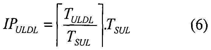
- the idle period IPUL D L is then given by: by taking into account a suitable dimensioning of the uplink/downlink required minimum idle duration TUL DL according to the above-mentioned requirements and the duration TSUL-
- the uplink/downlink required minimum duration T ULDL is equal to the summation of a uplink/downlink required duration T U LDL taken out of the uplink sub-frame UL and of a uplink/downlink required duration T 2 U L DL taken out of the downlink sub-frame DL 2 .
- Symbols embedded in the downlink sub-frame DL 2 are transmitted only during the effective transmission duration T EDL 2 and symbols embedded in the uplink sub-frame UL are transmitted during the effective transmission TE UL as depicted in Fig. 4c.
- the idle period IP U LD L is given by:
- Idle periods are reserved in a frame using a combination of one configuration depicted in Fig. 3 with one configuration depicted in Fig. 4.
- a configuration of Fig. 3 defines the effective duration of the uplink sub-frame UL as being equal to the total duration TU L , for example the configuration depicted in Fig.3a
- this effective transmission duration is reduced if a configuration of Fig. 4 defines that the idle period IPU L DL (or a part of it) is reserved in the end of the uplink sub-frame UL, for example configuration depicted in Fig. 4a.
- the effective parts of the uplink sub-frames UL sent by each user equipment UE are all received at a same time, called the synchronization time of uplink sub-frames, in order to be synchronized at the base station BS.
- a user equipment UE 1 knowing only the starting time t, of the reception of the downlink sub-frame DLi, the effective downlink sub-frame duration T EDLI and the duration of the idle period IP DLUL , is thus assumed to transmit the effective part of the uplink sub-frame UL at the time I 1 + T EDU + T RTUE . As depicted in Fig.
- time t being function of the distance between the base station BS and the user equipment UE 1 , transmitting the effective part of its uplink sub-frame UL at the time ( ⁇ + T EDLI + T RTUB d° es not allow the synchronization of all uplink sub-frames at the base station at the synchronization time.
- the timing advance means TAM are used.
- Fig. 5 represents chronograms which illustrate the timing advance mechanism used by the base station BS for synchronizing uplink sub-frames according to the state of the art.
- a timing alignment mechanism consists in waiting for a certain amount of time after the end of the reception of the first downlink sub-frame DLi before starting the transmission of the effective part of the uplink sub- frame UL 1 by a user equipment UE 1 in order to align its reception starting time T STUL at the base station BS together with the reception starting time of the effective parts of the uplink sub-frames sent by other user equipments also performing this mechanism.
- This timing alignment mechanism is also called a timing advance mechanism.
- the user equipment UE transmits its uplink sub-frame UL 1 at a time advanced by a timing advance value t A , from a reference time defined by the following equation: K " * * ⁇ * EDLX " * " ⁇ " DWL
- the base station BS sends to each user equipment UE 1 the timing advance value t A i from which a user equipment UE, defines the time at which it shall start the transmission of the effective part of the uplink sub-frame UL 1 .
- the timing advance mechanism requires thus the estimation at the base station BS of the propagation delay from the base station BS to each user equipment UE, in order to define such timing advance values I A ,.
- the timing advance values may be a fraction of the symbol duration.
- the effective transmission duration TE may be significantly reduced due to the over-dimensioning of idle periods IP DLUL and IPU LDL -
- the present invention aims at solving this problem by disclosing a method for communicating downlink and uplink sub-frames between a base station and at least one half duplex user equipment in a half duplex communication system, said method includes - a first transmission step in the course of which a first downlink sub-frame is transmitted by the base station to said at least one half duplex user equipment,
- said communication system being adapted to communicate also in full duplex downlink and uplink sub- frames between said base station and at least one full duplex user equipment
- the method is characterised in that said at least one full duplex user equipment is informed by the base station of a timing advance value defined in the course of said timing advance value definition step in order that the beginning of the effective parts of the uplink sub-frames sent by each of said at least one full duplex user equipment is received at said scheduled synchronisation time.
- the timing advance value transmitted to each of said half or full duplex user equipment being defined by two components, the summation of which is equal to said timing advance value, one of these two components being equal to said incremental timing advance value, the method is characterised in that the summation of said two components is executed by the base station.
- the timing advance value transmitted to each of said half or full duplex user equipment being defined by two components, the summation of which is equal to said timing advance value, one of these two components being equal to said incremental timing advance value, the addition of said two-components being computed by each of said at least one half or full duplex user equipment, the method is characterised in that said two components are transmitted to each of said at least one half or full duplex user equipment.
- the timing advance value transmitted to each of said half or full duplex user equipment being defined by two components, the summation of which is equal to said timing advance value, one of these two components being equal to said incremental timing advance value, the addition of said two-components being computed by each of said at least one half or full duplex user equipment, the method is characterised in that said incremental timing advance value is obtained from a memory of said at least one half or full duplex user equipment.
- said single idle period is a multiple of a symbol duration.
- said communication apparatus being adapted to communicate also in full duplex downlink and uplink sub- frames between said communication apparatus and at least one full duplex user equipment
- the communication apparatus is characterised in that it includes means for informing each of said at least one full duplex user equipment of a timing advance value in order that the beginning of the effective parts of the uplink sub-frames sent by each of said at least one full duplex user equipment is received at said scheduled synchronisation time.
- the timing advance value transmitted to each of said half or full duplex user equipment being defined by two components, the summation of which is equal to said timing advance value, one of these two components being equal to said incremental timing advance value, each of said at least one half or full duplex user equipment being adapted for adding said two- components
- the communication apparatus is characterised in that it includes means for transmitting said two components to each of said at least one half or full duplex user equipment.
- the present invention relates to an user equipment intended to communicate downlink and uplink sub-frames with an above-mentioned communication apparatus in a communication system, the transmitted timing advance value being defined by two components, the summation of which is equal to said timing advance value, one of these two components being equal to said incremental timing advance value, said user equipment is characterised in that it includes means for adding said two components. According to a variant of said user equipment, it further includes means for storing said incremental timing advance value.
- the transmitted timing advance value being defined by two components, the summation of which is equal to said timing advance value, one of these two components being equal to said incremental timing advance value
- said communication apparatus further includes means for adding said two components.
- the transmitted timing advance value being defined by two components, the summation of which is equal to said timing advance value, one of these two components being equal to said incremental timing advance value
- said communication apparatus is characterised in that it includes means for transmitting said two components and said at least one user equipment includes means for adding said two components.
- said at least one user equipment further includes means for storing said incremental timing advance value.
- the present invention relates to a frame of a signal exchanged between a base station and at least one half duplex user equipment, said frame including a first downlink sub-frame followed by at least a downlink/uplink required minimum idle duration, followed by an uplink sub-frame, followed by at least an uplink/downlink required minimum idle duration followed by a second downlink sub-frame, a scheduled synchronisation time is defined for synchronising the beginning of the effective parts of the uplink sub-frames at the base station, said frame is characterised in that said scheduled synchronisation time is such that the beginning of the effective part of said uplink sub-frame is separated from the end of the effective part of said first downlink sub-frame by a duration which is equal to the difference between a single idle period and an incremental timing advance value, said single idle period, having a duration greater than or equal to the summation of said downlink/uplink required minimum idle duration and said uplink/downlink required minimum idle duration, is reserved in either the end of said first downlink
- Fig. 1 represents a schema of a half duplex communication system SYS
- Fig. 3 and 4 represent examples of chronograms which depict frame idle periods reservations in the half duplex communication system SYS
- Fig. 5 represents chronograms which illustrate the timing advance mechanism used by a base station for synchronizing uplink sub-frames according to the state of the art
- Fig. 6 represents a chronogram which depicts an example of a frame of a half duplex communication system according to the present invention
- Fig. 7 represents chronograms which illustrate the use of the timing advance mechanism for synchronizing uplink sub-frames according to the present invention
- Fig. 8 represents a schema of a half duplex communication system SYSi according to the present invention
- Fig. 9 represents chronograms which illustrate the use of the timing advance mechanism for synchronizing uplink sub-frames in a full duplex communication system according to the present invention.
- TD L I may be different from T D L2
- TDL I may be different from T UL
- TDL 2 may be different from TUL-
- the frame includes a single idle period IP which is at least equal to the summation of the downlink/uplink required minimum idle duration T D LU L and the uplink/downlink required minimum idle duration T UL D L - Note that the single idle period IP is defined by over-dimensioning this summation as explained in the opening paragraph. The single idle period IP is taken out of either the end of the first downlink sub-frame DLi 1 or the beginning of the uplink sub-frame UL, or both.
- the frame does not include an idle period taken out of neither the end of the uplink sub-frame UL nor the beginning of the second downlink sub-frame DL 2 .
- Fig. 7 represents chronograms which illustrate the use of the timing advance mechanism for synchronizing the effective parts of uplink sub-frames according to the present invention.
- References of elements depicted in Fig. 5 and 6 which are identical to references of elements depicted in Fig. 7 are assigned to the same elements.
- the synchronization time T' ST U L is advanced by an incremental timing advance value ⁇ t A .
- the new synchronisation time T" S TU L is thus equal to t o + T EDLl + IP - At A .
- the downlink/uplink idle period For example, assuming and idle periods taken out of the preceding sub-frames, the downlink/uplink idle period
- IP D LU L would be equal to 70 ⁇ s
- the uplink/downlink idle period IP U LD L would be equal to 60 ⁇ s
- the idle period IP would be equal to 70 ⁇ s.
- the frame idle period duration is reduced.
- the present invention may also improve the coverage of the base station BS when IP- ⁇ tA is larger than the downlink/uplink idle period IPD LUL , which allows the base station BS to communicate with user equipments located farther than the effective cell radius R.
- T DL u L 43 ⁇ s
- Tu LDL 8 ⁇ s
- T SDL i 47 ⁇ s
- T S u L 45 ⁇ s
- idle periods taken out of the preceding sub-frames the downlink/uplink idle period IP D LU L would be equal to 47 ⁇ s
- the uplink/downlink idle period IPU L D L would be equal to 45 ⁇ s
- the idle period IP would be equal to 94 ⁇ s.
- the addition of the timing advance value tAi and the incremental timing advance value ⁇ t A is performed and the result is transmitted by the base station to each user equipment UE 1 .
- the incremental timing advance value ⁇ t A is transmitted by the base station to each of said user equipments.
- the incremental timing advance value ⁇ t A is stored by each of said user equipments.
- the half duplex communication system allowing block-wise transmissions the idle period IP is a multiple of a symbol duration which is either T SDLI or T SUL -
- the half duplex communication system allowing block-wise transmissions the idle period IP is a sum of a multiple of the duration T S D LI of symbols embedded into the first downlink sub- frame and a multiple of the duration T S U L of symbols embedded into the uplink sub- frame.
- Fig. 8 represents a schema of a half duplex communication system SYSi according to the present invention.
- the communication system SYSi is, for example, a Time Division Duplex (TDD) or a Half Duplex Frequency Division Duplex (HD FDD) communication system.
- the communication system SYSi allows half-duplex communications between a communication apparatus BS, which is for example a base station and at least one user equipments UE, and/or at least one user equipment UE j which are both, for example mobile phones or fixed wireless terminals.
- a communication apparatus BS which is for example a base station and at least one user equipments UE, and/or at least one user equipment UE j which are both, for example mobile phones or fixed wireless terminals.
- the uplink sub-frame UL is then itself followed by the second downlink sub-frame DL 2 transmitted to the user equipments UE 1 (or UE j ), the transmission of the effective part of the first downlink sub-frame DLi being separated from the reception of the effective part of the uplink sub-frame UL by at least a downlink/uplink required minimum idle duration T DL U L , the reception of the effective part of said uplink sub-frame UL is separated from the transmission of the effective part of said second downlink sub-frame DL 2 by at least an uplink/downlink required minimum idle duration TUL D L-
- said communication apparatus BS includes :
- FIPRMi for reserving a single idle period IP taken out of either the end of said first downlink sub-frame DLi, or the beginning of said uplink sub-frame UL, or both, said single idle period IP having a duration greater than or equal to the summation of said downlink/uplink required minimum idle duration T D LU L and said uplink/downlink required minimum idle duration TULDL,
- TAMi for defining a timing advance value I A , (or . AJ ) for the user equipments UE 1 (or UE j ) in order that the effective parts of the uplink sub-frames sent by each of said user equipments are received at a scheduled synchronisation time T' S TUL, said scheduled synchronisation time T' STUL being defined such that the beginning of the reception of the effective part of said uplink sub-frame is separated from the end of the transmission of the effective part of said first downlink sub-frames by the duration of said single idle period IP, and - means IATM for defining an incremental timing advance value ⁇ t A to the timing advance value t A i (or t Aj ) of the user equipment UE, (or UE j ), said incremental timing advance value ⁇ t A being greater than or equal to said uplink/downlink required minimum idle duration TULD L and lower than or equal to the difference between the duration of said single idle period IP and said downlink/uplink required minimum idle duration TDLUL-
- the communication apparatus BS includes means ADM for adding said incremental timing advance value ⁇ t A to the timing advance value t A i of one of user equipments UE 1 .
- the communication apparatus BS includes means for transmitting said incremental timing advance value
- the user equipment UE j includes means for adding the incremental timing advance value ⁇ tA to the timing advance value t A) .
- Fig. 9 represents chronograms which illustrate the use of the timing advance mechanism for synchronizing uplink sub-frames in a full duplex communication system according to the present invention.
- downlink and uplink sub-frames are transmitted simultaneously. Moreover, no idle periods are reserved in the frame which is depicted here as a set of downlink sub-frames DL and a set of uplink sub-frames UL having the same duration T DL -
- the beginning of the uplink sub-frames sent by each user equipment UE are received at a same time instant thanks to the timing advance mechanism.
- the incremental timing advance value ⁇ t A is added to each timing advance value t A i to be used to perform the timing advance mechanism at each user equipment.
Landscapes
- Engineering & Computer Science (AREA)
- Computer Networks & Wireless Communication (AREA)
- Signal Processing (AREA)
- Mobile Radio Communication Systems (AREA)
Abstract
Description


Claims
Priority Applications (3)
| Application Number | Priority Date | Filing Date | Title |
|---|---|---|---|
| JP2008536958A JP4852615B2 (en) | 2005-10-26 | 2006-09-28 | Method for communicating downlink and uplink subframes in a communication system |
| KR1020087010367A KR101254268B1 (en) | 2005-10-26 | 2006-09-28 | Method for communicating downlink and uplink sub-frames in a half duplex communication system |
| US12/091,139 US8068444B2 (en) | 2005-10-26 | 2006-09-28 | Method and apparatus for communicating downlink and uplink sub-frames in a half duplex communication system |
Applications Claiming Priority (4)
| Application Number | Priority Date | Filing Date | Title |
|---|---|---|---|
| EP05292273 | 2005-10-26 | ||
| EP05292273.9 | 2005-10-26 | ||
| EP06290095.6 | 2006-01-13 | ||
| EP06290095A EP1821429A3 (en) | 2005-10-26 | 2006-01-13 | Method and apparatus for communicating downlink and uplink sub-frames in a half duplex communication system |
Publications (1)
| Publication Number | Publication Date |
|---|---|
| WO2007048478A1 true WO2007048478A1 (en) | 2007-05-03 |
Family
ID=37487478
Family Applications (1)
| Application Number | Title | Priority Date | Filing Date |
|---|---|---|---|
| PCT/EP2006/009432 Ceased WO2007048478A1 (en) | 2005-10-26 | 2006-09-28 | Method and apparatus for communicating downlink and uplink sub-frames in a half duplex communication system |
Country Status (1)
| Country | Link |
|---|---|
| WO (1) | WO2007048478A1 (en) |
Cited By (8)
| Publication number | Priority date | Publication date | Assignee | Title |
|---|---|---|---|---|
| WO2009049537A1 (en) * | 2007-10-12 | 2009-04-23 | Huawei Technologies Co., Ltd. | A data transmission method and device under h-fdd |
| WO2009089775A1 (en) * | 2008-01-07 | 2009-07-23 | Huawei Technologies Co., Ltd. | Sleeping method for wireless system and terminal device |
| JP2010536257A (en) * | 2007-08-03 | 2010-11-25 | クゥアルコム・インコーポレイテッド | Method and apparatus for efficient selection and acquisition of systems utilizing OFDM or SC-FDM |
| CN101911629A (en) * | 2008-01-11 | 2010-12-08 | Lg电子株式会社 | Method for adjusting transmission timing and transmitting continuous packets and its mobile station |
| JP2010541381A (en) * | 2007-09-27 | 2010-12-24 | アルカテル−ルーセント ユーエスエー インコーポレーテッド | Method for half-duplex and full-duplex subscriber station operation in frequency division duplex systems |
| CN101940008A (en) * | 2007-10-08 | 2011-01-05 | 诺基亚西门子通信公司 | Link Utilization Techniques for Half-duplex and Full-duplex Stations in Wireless Networks |
| US7953028B2 (en) | 2008-01-14 | 2011-05-31 | Telefonaktiebolaget Lm Ericsson (Publ) | Methods and apparatus for improved receiver performance in half-duplex wireless terminals |
| WO2022127448A1 (en) * | 2020-12-15 | 2022-06-23 | 中兴通讯股份有限公司 | Message transmission method, terminals and storage medium |
Citations (4)
| Publication number | Priority date | Publication date | Assignee | Title |
|---|---|---|---|---|
| EP1209938A1 (en) * | 2000-11-17 | 2002-05-29 | Samsung Electronics Co., Ltd. | System and method for measuring propagation delay in an narrowband TDD CDMA mobile communication system |
| EP1213855A1 (en) * | 2000-12-08 | 2002-06-12 | Lucent Technologies Inc. | Frame structure for TDD telecommunication systems |
| US20040002334A1 (en) * | 2002-05-13 | 2004-01-01 | Samsung Electronics Co., Ltd. | Method of performing inter-rat measurement for a handover from NB-TDD to GSM |
| US20040052271A1 (en) * | 2002-08-29 | 2004-03-18 | Lg Electronics Inc. | Mode switching in transceiver of a mobile terminal |
-
2006
- 2006-09-28 WO PCT/EP2006/009432 patent/WO2007048478A1/en not_active Ceased
Patent Citations (4)
| Publication number | Priority date | Publication date | Assignee | Title |
|---|---|---|---|---|
| EP1209938A1 (en) * | 2000-11-17 | 2002-05-29 | Samsung Electronics Co., Ltd. | System and method for measuring propagation delay in an narrowband TDD CDMA mobile communication system |
| EP1213855A1 (en) * | 2000-12-08 | 2002-06-12 | Lucent Technologies Inc. | Frame structure for TDD telecommunication systems |
| US20040002334A1 (en) * | 2002-05-13 | 2004-01-01 | Samsung Electronics Co., Ltd. | Method of performing inter-rat measurement for a handover from NB-TDD to GSM |
| US20040052271A1 (en) * | 2002-08-29 | 2004-03-18 | Lg Electronics Inc. | Mode switching in transceiver of a mobile terminal |
Cited By (19)
| Publication number | Priority date | Publication date | Assignee | Title |
|---|---|---|---|---|
| JP2010536257A (en) * | 2007-08-03 | 2010-11-25 | クゥアルコム・インコーポレイテッド | Method and apparatus for efficient selection and acquisition of systems utilizing OFDM or SC-FDM |
| US8331286B2 (en) | 2007-08-03 | 2012-12-11 | Qualcomm Incorporated | Method and apparatus for efficient selection and acquisition of systems utilizing OFDM or SC-FDM |
| JP2010541381A (en) * | 2007-09-27 | 2010-12-24 | アルカテル−ルーセント ユーエスエー インコーポレーテッド | Method for half-duplex and full-duplex subscriber station operation in frequency division duplex systems |
| CN101940008A (en) * | 2007-10-08 | 2011-01-05 | 诺基亚西门子通信公司 | Link Utilization Techniques for Half-duplex and Full-duplex Stations in Wireless Networks |
| CN101940008B (en) * | 2007-10-08 | 2014-07-02 | 诺基亚西门子通信公司 | Techniques for link utilization for half-duplex and full-duplex stations in a wireless network |
| WO2009049537A1 (en) * | 2007-10-12 | 2009-04-23 | Huawei Technologies Co., Ltd. | A data transmission method and device under h-fdd |
| WO2009089775A1 (en) * | 2008-01-07 | 2009-07-23 | Huawei Technologies Co., Ltd. | Sleeping method for wireless system and terminal device |
| CN101483476B (en) * | 2008-01-07 | 2012-06-27 | 华为技术有限公司 | Sleeping method for differentiating uplink and downlink sub-frames |
| CN101911629B (en) * | 2008-01-11 | 2013-07-24 | Lg电子株式会社 | Method for adjusting transmission timing and transmitting continuous packets and mobile station thereof |
| US8339936B2 (en) | 2008-01-11 | 2012-12-25 | Lg Electronics Inc. | Method of resolving overlaps in data transmission and user equipment therefor |
| US8467373B2 (en) | 2008-01-11 | 2013-06-18 | Lg Electronics Inc. | Method of resolving overlaps in data transmission and user equipment therefor |
| CN101911629A (en) * | 2008-01-11 | 2010-12-08 | Lg电子株式会社 | Method for adjusting transmission timing and transmitting continuous packets and its mobile station |
| US8767706B2 (en) | 2008-01-11 | 2014-07-01 | Lg Electronics Inc. | Method of resolving overlaps in data transmission and user equipment therefor |
| CN103281284B (en) * | 2008-01-11 | 2016-03-16 | Lg电子株式会社 | For adjusting the method and the travelling carriage thereof that send timing and send grouping continuously |
| US9432993B2 (en) | 2008-01-11 | 2016-08-30 | Lg Electronics Inc. | Method of resolving overlaps in data transmission and user equipment therefor |
| US10070436B2 (en) | 2008-01-11 | 2018-09-04 | Lg Electronics Inc. | Method of resolving overlaps in data transmission and user equipment therefor |
| US11647487B2 (en) | 2008-01-11 | 2023-05-09 | Lg Electronics Inc. | Method of resolving overlaps in data transmission and user equipment therefor |
| US7953028B2 (en) | 2008-01-14 | 2011-05-31 | Telefonaktiebolaget Lm Ericsson (Publ) | Methods and apparatus for improved receiver performance in half-duplex wireless terminals |
| WO2022127448A1 (en) * | 2020-12-15 | 2022-06-23 | 中兴通讯股份有限公司 | Message transmission method, terminals and storage medium |
Similar Documents
| Publication | Publication Date | Title |
|---|---|---|
| EP2134006B1 (en) | Method for communicating downlink and uplink sub-frames in a half duplex communication system | |
| US9107077B2 (en) | Method and system for time synchronization of WiMAX and LTE-TDD networks | |
| KR101385495B1 (en) | Terminal access method, system and associated devices | |
| EP2169850B1 (en) | Tdd system signal transmission method and the adoptive frame structure thereof | |
| EP2688227B1 (en) | Technique for performing a random access procedure over a radio interface | |
| KR101160243B1 (en) | Communication method and device | |
| KR101770906B1 (en) | Communication method and user equipment in mixed cellular and d2d network | |
| KR101790530B1 (en) | Method and apparatus for detecting uplink synchronization signal of each level in wireless access system supporting high-frequency band | |
| CN110945953B (en) | System and method for early random access preamble transmission | |
| WO2007048478A1 (en) | Method and apparatus for communicating downlink and uplink sub-frames in a half duplex communication system | |
| CN101005307B (en) | Synchronizing method for broad band time division duplex honey comb system and cell primary searching | |
| WO2008115105A1 (en) | A method and a device for reduced interference in a cellular access system. | |
| WO2009041881A2 (en) | Transmission of reference signal between uplink and downlink timeslots | |
| KR20100132464A (en) | Transmission timing adjusting method and apparatus therefor | |
| KR100859716B1 (en) | Cell search method for OFDM based FDD/TDD dual mode mobile station and base station transmission scheme | |
| US8130743B2 (en) | Cellular radiotelephone signal permitting synchronization of a supplementary channel by means of a principal channel and corresponding method, terminal and base station | |
| WO2025171567A1 (en) | Satellite switch with resynchronization | |
| CN102037771A (en) | Radio communication system, base station, terminal, radio communication method, and program | |
| WO2005074180A1 (en) | Wireless access system | |
| JP2008244860A (en) | Wireless communication system, base station and terminal |
Legal Events
| Date | Code | Title | Description |
|---|---|---|---|
| WWE | Wipo information: entry into national phase |
Ref document number: 200680040025.8 Country of ref document: CN |
|
| 121 | Ep: the epo has been informed by wipo that ep was designated in this application | ||
| WWE | Wipo information: entry into national phase |
Ref document number: 12091139 Country of ref document: US |
|
| ENP | Entry into the national phase |
Ref document number: 2008536958 Country of ref document: JP Kind code of ref document: A |
|
| NENP | Non-entry into the national phase |
Ref country code: DE |
|
| WWE | Wipo information: entry into national phase |
Ref document number: 1020087010367 Country of ref document: KR |
|
| 122 | Ep: pct application non-entry in european phase |
Ref document number: 06792312 Country of ref document: EP Kind code of ref document: A1 |
|
| WWE | Wipo information: entry into national phase |
Ref document number: 1020107018028 Country of ref document: KR |