WO2006094255A1 - Radiated power control for a multi-antenna transmission - Google Patents
Radiated power control for a multi-antenna transmissionInfo
- Publication number
- WO2006094255A1 WO2006094255A1 PCT/US2006/007811 US2006007811W WO2006094255A1 WO 2006094255 A1 WO2006094255 A1 WO 2006094255A1 US 2006007811 W US2006007811 W US 2006007811W WO 2006094255 A1 WO2006094255 A1 WO 2006094255A1
- Authority
- WO
- WIPO (PCT)
- Prior art keywords
- data transmission
- array gain
- antenna pattern
- synthesized antenna
- eigenvalues
- Prior art date
- Legal status (The legal status is an assumption and is not a legal conclusion. Google has not performed a legal analysis and makes no representation as to the accuracy of the status listed.)
- Ceased
Links
Classifications
-
- H—ELECTRICITY
- H04—ELECTRIC COMMUNICATION TECHNIQUE
- H04W—WIRELESS COMMUNICATION NETWORKS
- H04W52/00—Power management, e.g. Transmission Power Control [TPC] or power classes
- H04W52/04—Transmission power control [TPC]
- H04W52/38—TPC being performed in particular situations
- H04W52/42—TPC being performed in particular situations in systems with time, space, frequency or polarisation diversity
-
- H—ELECTRICITY
- H04—ELECTRIC COMMUNICATION TECHNIQUE
- H04W—WIRELESS COMMUNICATION NETWORKS
- H04W52/00—Power management, e.g. Transmission Power Control [TPC] or power classes
- H04W52/04—Transmission power control [TPC]
- H04W52/30—Transmission power control [TPC] using constraints in the total amount of available transmission power
-
- Y—GENERAL TAGGING OF NEW TECHNOLOGICAL DEVELOPMENTS; GENERAL TAGGING OF CROSS-SECTIONAL TECHNOLOGIES SPANNING OVER SEVERAL SECTIONS OF THE IPC; TECHNICAL SUBJECTS COVERED BY FORMER USPC CROSS-REFERENCE ART COLLECTIONS [XRACs] AND DIGESTS
- Y02—TECHNOLOGIES OR APPLICATIONS FOR MITIGATION OR ADAPTATION AGAINST CLIMATE CHANGE
- Y02D—CLIMATE CHANGE MITIGATION TECHNOLOGIES IN INFORMATION AND COMMUNICATION TECHNOLOGIES [ICT], I.E. INFORMATION AND COMMUNICATION TECHNOLOGIES AIMING AT THE REDUCTION OF THEIR OWN ENERGY USE
- Y02D30/00—Reducing energy consumption in communication networks
- Y02D30/70—Reducing energy consumption in communication networks in wireless communication networks
Definitions
- the present invention relates generally to communication, and more specifically to techniques for controlling radiated power for a multi-antenna transmission.
- Wireless communication networks are widely deployed to provide various communication services such as data, voice, video, and so on. These networks include wireless wide area networks (WWANs) that provide communication coverage for large geographic areas (e.g., cities), wireless local area networks (WLANs) that provide communication coverage for medium-size geographic areas (e.g., buildings and campuses), and wireless personal area networks (WPANs) that provide communication coverage for small geographic areas (e.g., homes).
- WWANs wireless wide area networks
- WLANs wireless local area networks
- WPANs wireless personal area networks
- a wireless network typically includes one or more access points (or base stations) that support communication for one or more user terminals (or wireless devices).
- a wireless communication network typically operates in a designated frequency band.
- the Federal Communications Commission Federal Communications Commission
- FCC Federal Communications Commission
- an IEEE 802.11 WLAN typically operates in a U-NII band that covers 5.15 to 5.35 gigaHertz (GHz) and 5.725 to 5.825 GHz.
- GHz gigaHertz
- a wireless station (which may be an access point or a user terminal) needs to limit its radiated power in any spatial direction to within a level mandated by the FCC in order to qualify for operation in the U-NII band.
- the radiated power in a given direction is determined by the amount of transmit power applied to the antenna(s) at a wireless station and an antenna pattern formed by the antenna(s). If the wireless station is equipped with multiple antennas, then these antennas may be used to synthesize an antenna pattern that increases the radiated power in a specific spatial direction, e.g., toward a receiving station.
- the antenna pattern is often not easy to ascertain because it is dependent on various factors such as the physical attributes of each antenna, the layout and arrangement of the antennas, and so on. If the antenna pattern is not known, then the wireless station may assume a maximum possible gain for the antenna pattern and may set the transmit power level accordingly in order to meet regulatory limit. However, in many instances, the maximum gain is not achieved for any spatial direction, and setting the transmit power level based on this maximum gain results in a lower SNR and/or reduced range, both of which are undesirable. [0005] There is therefore a need in the art for techniques to control radiated power for a multi-antenna transmission.
- a method of controlling radiated power for a data transmission in which an array gain is estimated based on a synthesized antenna pattern for the data transmission, and the transmit power for the data transmission is limited based on the array gain and a radiated power limit.
- an apparatus in a wireless communication network which includes a controller to estimate an array gain based on a synthesized antenna pattern for a data transmission and a control unit to limit transmit power for the data transmission based on the array gain and a radiated power limit.
- an apparatus which includes means for estimating an array gain based on a synthesized antenna pattern for a data transmission and means for limiting transmit power for the data transmission based on the array gain and a radiated power limit.
- FIG. 1 shows a transmitting station and a receiving station.
- FIG. 2 illustrates the results of eigenvalue decomposition for multiple subbands.
- FIG. 3 shows a process for controlling the radiated power for a data transmission.
- FIG. 4 shows a block diagram of the transmitting and receiving stations.
- FIG. 1 shows a wireless communication network 100 with a transmitting station
- FIG. 1 shows transmitting station 110 performing spatial processing by multiplying the symbols for each transmit antenna i with a single complex gain g ( by a multiplier 112. In general, the spatial processing may be more complex, as described below.
- the outputs of multipliers 112a through 112t are further processed and transmitted from T transmit antennas 114a through 114t, respectively.
- the radiated power of a transmit antenna array typically has different intensities in different spatial directions.
- the time-averaged power density of the power radiated from the transmit antenna array may be given by the real part of a Poynting vector, as follows:
- p( ⁇ , ⁇ ) is the time-averaged power density for the transmit antenna array
- H is the magnetic field strength for the transmit antenna array
- ⁇ is the impedance of free space, which is equal to 120 ⁇ ;
- E tQtai ( ⁇ , ⁇ ) is the total electric field strength for the transmit antenna array.
- the total electric field strength E mal ( ⁇ , ⁇ ) and the time-averaged power density p( ⁇ , ⁇ ) may be expressed as functions of spatial directions, with ⁇ being the angle for azimuth (or horizontal rotation) and ⁇ being the angle for elevation (or vertical rotation).
- the electric field E( ⁇ , ⁇ ) is dependent on the design of the transmit antenna. For example, different electric field patterns are obtained for a dipole antenna, a whip antenna, a planar antenna, and so on.
- the total electric field ⁇ toial ( ⁇ , ⁇ ) is the sum of the complex electric field ⁇ t ⁇ , ⁇ ) from each radiation element.
- the total radiated power (TRP) from the antenna array may be obtained by integrating the total time-averaged power density across the surface of a reference sphere, as follows:
- TRP J jp( ⁇ , ⁇ ) - r 2 -d ⁇ -d ⁇ .
- the total radiated power is indicative of the total power radiated from the T transmit antennas in all spatial directions.
- EIRP effective isotropic radiated power
- the maximum directivity of the antenna array, D may be expressed as:
- the maximum gain of the antenna array which is also called the total array gain
- Gtotah may be expressed as:
- G ⁇ D ⁇ Eq (5)
- ⁇ the efficiency of the antenna array
- P 1x the total transmit power feeding all elements of the transmit antenna array.
- the FCC defines specific limits on the EIRP for a wireless station operating in the U-NII band. If the total array gain G tota i is known or can be computed, then the total transmit power P 1x can be adjusted such that the wireless station meets the EIRP limits imposed by the FCC. However, as shown in equations (1) through (5), the total array gain Gtotai is not easy to compute or determine.
- the EIRP of the antenna array is dependent on the maximum value of the total time-averaged power density p( ⁇ , ⁇ ) , or P n x , which in turn is dependent on the maximum value of the total electric field ⁇ tot ⁇ ( ⁇ , ⁇ ) .
- P 1113x may be expressed as:
- E max is the maximum of E tot ⁇ ( ⁇ , ⁇ ) .
- E max is dependent on a complex gain g. and an electric field pattern K t ( ⁇ , ⁇ ) for each of the T transmit antennas in the array and may be expressed as:
- k 0 is a free space wave vector
- R 1 is a vector pointing from a phase reference point to transmit antenna i; and U 1 . is a unit vector pointing from the phase reference point to a far-field point.
- G The term • ⁇ ?*° 'R ' "Uf corresponds to the gain of the antenna array (or array gain) which may be denoted as G may .
- the array gain may also be called an array factor, a steering gain, and so on.
- max (K( ⁇ , ⁇ )) corresponds to the gain of an individual radiation element (or element gain) which may be denoted as G ant .
- the element gain G ant is indicative of how well a given transmit antenna increases the effective radiated power in a particular spatial direction in comparison to an isotropic antenna.
- the total array gain G tota i may be estimated using equation (8), as follows:
- the total array gain may be conservatively estimated as follows:
- G ant dB1 is the gain of an antenna element given in units of decibels (dBi); and C total dB i s * ne total array gain given in units of dB.
- dBi is equal to 10 times the logarithm (in base 10) of the electric field intensity of the transmit antenna divided by the electric field intensity of the isotropic antenna at the same distance.
- the transmit power may be limited as follows:
- EIRP 111n; , dBm is the EIRP limit given in units of dBm;
- Equation (11) indicates that the total transmit power applied to the antenna array may be reduced by the total array gain G totaI dB in order to ensure that the EIRP limit is met. In many instances, the total array gain estimated by equation (10) is not realized. This implies that limiting the transmit power as shown in equation (11) is a conservative strategy that can result in reduced range and/or data rate.
- a multiple-input multiple-output (MIMO) channel formed by the T transmit antennas and the R receive antennas may be characterized by an R xT channel response matrix H .
- This matrix H may be given as:
- the channel response matrix H may be diagonalized to obtain multiple (S) eigenmodes of H , where S ⁇ min ⁇ T, R ⁇ .
- the eigenmodes may be considered as orthogonal spatial channels of the MIMO channel.
- the diagonalization may be achieved by performing either singular value decomposition of H or eigenvalue decomposition of a correlation matrix of H .
- the eigenvalue decomposition may be expressed as:
- R is a T XT correlation matrix of H ;
- E is a TxT unitary matrix whose columns are eigenvectors of R ; ⁇ is a T x T diagonal matrix of eigenvalues of R ; and " H " denotes a conjugate transpose.
- the columns of a unitary matrix are orthogonal to one another, and each column has unit power.
- the diagonal matrix ⁇ contains possible non-zero values along the diagonal and zeros elsewhere.
- the diagonal elements of ⁇ are eigenvalues of R and represent the power gains for the S eigenmodes of H .
- the eigenvalues may be ordered or sorted such that A 1 ⁇ A 2 ⁇ ...
- a 1 is the largest eigenvalue and A s is the smallest eigenvalue.
- the largest eigenvalue A 1 is also called the principal eigenvalue A pem
- the eigenmode corresponding to A 1 is called the principal eigenmode.
- the downlink (or forward link) and the uplink (or reverse link), which are the communication links between an access point and a user terminal share the same frequency band.
- the downlink and uplink channel responses may be assumed to be reciprocal of one another, after calibration has been performed to account for differences in the transmit and receive chains at the access point and the user terminal. That is, if H represents the channel response matrix from antenna array A to antenna array B, then a reciprocal channel implies that the coupling from array B to array A is given by H r , where H r denotes the transpose of H .
- the transmitting station may estimate H based on a pilot received from the receiving station and may decompose H to obtain E and ⁇ .
- the downlink and uplink are allocated different frequency bands, and the downlink channel response matrix may not be well correlated with the uplink channel response matrix.
- the receiving station may estimate H based on the pilot received from the transmitting station, decompose H to obtain E and ⁇ , and send E and ⁇ or equivalent information back to the transmitting station.
- the transmitting station may transmit data using eigensteering to improve performance.
- the transmitting station uses the eigenvectors in E to transmit data on one or more eigenmodes of H, which typically provides better performance than simply transmitting data from the T transmit antennas without any spatial processing.
- the receiving station uses the eigenvectors in E to receive the data transmission on the eigenmode(s) of H .
- Table 1 shows the spatial processing performed by the transmitting station, the received symbols at the receiving station, and the spatial processing performed by the receiving station for eigensteering.
- s is a TxI vector with up to S data symbols to be transmitted on the
- x es is a TxI vector with T transmit symbols to be sent from the T transmit antennas
- r es is an RxI vector with R received symbols obtained from the R receive antennas
- n is an R xI noise vector
- s es is a TxI vector with up to S detected data symbols, which are estimates of the transmitted data symbols in s .
- the array gain may be estimated based on the eigenvalue /l pem for the principal eigenmode, as follows:
- G dB is the array gain for the principal eigenmode given in units of dB.
- the principal eigenvalue ⁇ pem is typically less than the number of transmit antennas, or ⁇ - pem ⁇ T •
- the array gain may be limited to a predetermined value, e.g., G pe ⁇ lj dB ⁇ 4 dB or some other value.
- the total transmit power may then be limited using equations (11) and (14), as follows:
- the transmit power is radiated in different spatial directions determined by the eigenvectors for these eigenmodes.
- the array gain may be estimated based on the eigenvalues for the eigenmodes used for data transmission, as follows:
- M is the number of eigenmodes used for data transmission
- G mem, dB is the array gain for the multiple eigenmodes given in units of dB.
- the total transmit power may then be limited as shown follows:
- Equation (17) is similar to equation (15), with the array gain G 1n ⁇ dB for the multiple eigenmodes replacing the array gain G peiMB for the principal eigenmode. Comparing equations (11), (15) and (17), since G pe ⁇ dB ⁇ G n ⁇ dB ⁇ 10- log 10 (T) in most instances, higher transmit power may be used for data transmission on one or multiple eigenmodes to achieve better system performance.
- Network 100 may utilize a multi-carrier modulation technique such as orthogonal frequency division multiplexing (OFDM).
- OFDM effectively partitions the overall system bandwidth into multiple (K) orthogonal frequency subbands, which are also called tones, subcarriers, bins, and frequency channels.
- K orthogonal frequency division multiplexing
- each subband is associated with a respective subcarrier that may be modulated with data.
- a channel response matrix H(fc) may be obtained for each subband k and decomposed to obtain a matrix E(£) of eigenvectors and a matrix ⁇ (k) of eigenvalues for that subband.
- the eigenvalues for each subband may be ordered from largest to smallest, and the eigenvectors for that subband may be ordered correspondingly.
- FIG. 2 graphically illustrates the results of the eigenvalue decomposition for the
- Axis 212 runs along the diagonal of each matrix A(k) and represents the spatial dimension.
- a wideband eigenmode m is formed by eigenmode m for all K subbands.
- the principal wideband eigenmode is associated with the largest eigenvalue A 1 (Jc) for each of the K subbands.
- the set of eigenvalues for each wideband eigenmode is shown by the shaded boxes along a dashed line 214. For each wideband eigenmode that experiences frequency selective fading, the eigenvalues for that wideband eigenmode may be different for different values of k.
- the transmitting and receiving stations may perform the spatial processing shown in Table 1 for each subband used for data transmission.
- the array gain may be estimated based on the largest eigenvalue for all K subbands of the principal wideband eigenmode, as follows:
- G pweiMB is the array gain for the principal wideband eigenmode.
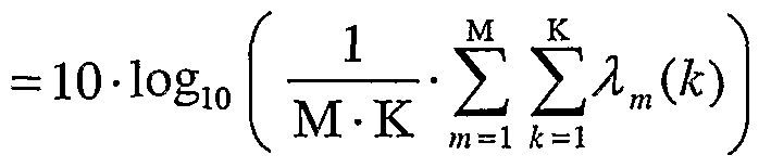
- the array gain may be estimated based on the average of the K eigenvalues for the principal wideband eigenmode, as follows:
- the total transmit power may then be limited as shown in equation (15), albeit with the array gain G pwe ⁇ i(dB for the principal wideband eigenmode replacing the array gain G pem>dB for the principal eigenmode.
- the transmit power is radiated in different spatial directions determined by the eigenvectors for these wideband eigenmodes.
- the array gain may be estimated based on the eigenvalues for the wideband eigenmodes used for data transmission, as follows:
- the transmitting station may also transmit data using spatial spreading to improve diversity.
- Spatial spreading refers to the transmission of a symbol from multiple transmit antennas simultaneously, possibly with different amplitudes and/or phases determined by a steering vector used for that symbol. Spatial spreading is also called steering diversity, transmit steering, pseudo-random transmit steering, and so on.
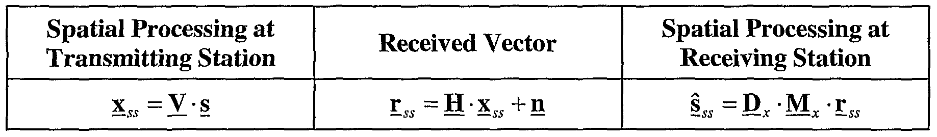
- Table 2 shows the spatial processing performed by the transmitting station, the received symbols at the receiving station, and the spatial processing performed by the receiving station for spatial spreading.
- s is a T x 1 data vector
- x ss is a T x 1 transmit vector
- r ss is an R xI received vector
- ⁇ _ofio is a TxI detected vector
- V is a TxT steering matrix for spatial spreading
- M 1 is a TxR spatial filter matrix
- 1 D x is a T xT diagonal matrix.
- the matrices M x and O x may be derived using, for example, a minimum mean square error (MMSE) technique or a channel correlation matrix inversion (CCMI) technique.
- MMSE minimum mean square error
- CCMI channel correlation matrix inversion
- the transmitting station performs spatial processing with different steering matrices V across time and/or frequency dimensions so that the data transmission observes an ensemble of effective channels.
- the steering matrices may be pseudo-random matrices, matrices generated with a base matrix (e.g., a Walsh matrix or a Fourier matrix) and different combinations of scalars (e.g., 1, -1, +j, and -j) for the rows of the base matrix, or some other matrices.
- the array gain may be estimated as
- G s* dB 0 dB or may be set to some other value.
- the transmit power may then be limited as shown in equation (15), albeit with the array gain G; ⁇ . aytdB for spatial spreading replacing the array gain G peiMB for the principal eigenmode.
- FIG. 3 shows a process 300 for controlling the radiated power for a data transmission sent from multiple transmit antennas.
- a synthesized antenna pattern is determined based on at least one steering vector used for spatial processing for the data transmission (block 312). Different spatial processing modes or techniques have different synthesized antenna patterns. For example, eigensteering generates a synthesized antenna pattern that is directed toward the receiving station whereas spatial spreading generates a spatially spread synthesized antenna pattern.
- an array gain is estimated based on the synthesized antenna pattern (block 314). The array gain may be estimated based on the spatial processing mode used for the data transmission and applicable parameters (e.g., eigenvalues) for that mode.
- the array gain may be estimated based on the eigenvalue for the principal eigenmode, the largest or average eigenvalue for the principal wideband eigenmode, multiple eigenvalues for multiple subbands of at least one wideband eigenmode, and so on.
- the array gain may be set to a predetermined value (e.g., 0 dB).
- the array gain may also be set to different predetermined values for different spatial spreading modes. For example, the array gain may be set to a first value (e.g., from 0 to 4 dB) for eigensteering depending on number of eigenmodes used, and to a second value (e.g., 0 dB) for spatial spreading.
- An element gain for each transmit antenna used for data transmission may also be ascertained or estimated (block 316).
- the transmit power for the data transmission is then limited based on the array gain, the element gain, and a radiated power limit (e.g., an EIRP limit) (block 318).
- a radiated power limit e.g., an EIRP limit
- FIG. 4 shows a block diagram of transmitting station 110 and receiving station
- Transmitting station 110 may be an access point or a user terminal.
- Receiving station 150 may also be an access point or a user terminal.
- a transmit (TX) data processor 420 receives traffic data from a data source 412 and processes (e.g., encodes, interleaves, and symbol maps) the traffic data to generate data symbols, which are modulation symbols for data.
- a TX spatial processor 422 receives the data symbols from TX data processor 420, multiplexes in pilot symbols, performs spatial processing (e.g., as shown in Tables 1 and 2 for eigensteering and spatial spreading, respectively), and provides T streams of transmit symbols to a TX gain control unit 424.
- Unit 424 scales the transmit symbols such that the total transmit power P tXidBm ensures compliance with the EIRP limit
- Unit 424 provides T scaled transmit symbol streams to T transmitter units (TMTR) 426a through 426t.
- TMTR transmitter units
- Each transmitter unit 426 performs OFDM modulation (if applicable) to generate data chips, and further processes (e.g., converts to analog, amplifies, filters, and frequency upconverts) its data chips to generate a modulated signal.
- Transmitter units 426a through 426t provide T modulated signals for transmission from T antennas 114a through 114t, respectively.
- R antennas 152a through 152r receive the T transmitted signals, and each antenna 152 provides a received signal to a respective receiver unit (RCVR) 454.
- Each receiver unit 454 processes its received signal and provides a stream of received symbols to a receive (RX) spatial processor 456.
- RX spatial processor 456 performs receiver spatial processing (or spatial matched filtering) on the received symbols from all R receiver units 454 (e.g., as shown in Tables 1 and 2) and provides detected data symbols.
- An RX data processor 460 then processes (e.g., symbol demaps, deinterleaves, and decodes) the detected data symbols and provides decoded data to a data sink 462.
- Controllers 430 and 470 control the operation of the processing units at transmitting station 110 and receiving station 150, respectively.
- Memory units 432 and 472 store data and/or program codes used by controllers 430 and 470, respectively.
- receiving station 150 may transmit a pilot to transmitting station 110.
- Transmitting station 110 may derive a channel response matrix for each subband used for data transmission and decompose each channel response matrix to obtain the eigenvalues and eigenvectors for that subband.
- Transmitting station 110 may perform (1) spatial processing for eigensteering based on the eigenvectors, (2) spatial processing for spatial spreading based on steering matrices, (3) spatial processing based on some other technique, or (3) no spatial processing at all.
- Controller 430 may perform process 300 in FIG.
- the synthesized antenna pattern determines the synthesized antenna pattern based on the steering vectors used for spatial processing, estimate the array gain based on the synthesized antenna pattern, estimate the element gain for each transmit antenna, and limit the transmit power based on the array gain, the element gain, and the EIRP limit.
- the techniques described herein allow the transmitting station to estimate the array gain based on the synthesized antenna pattern formed by the steering vectors used for data transmission.
- the transmit power for the data transmission is then limited (e.g., by scaling the steering vectors and/or adjusting the transmit power applied to each antenna) to ensure that the EIRP limits are met regardless of the channel characteristics.
- the radiated power control techniques described herein may be implemented by various means. For example, these techniques may be implemented in hardware, software, or a combination thereof.
- the processing units used to control the radiated power may be implemented within one or more application specific integrated circuits (ASICs), digital signal processors (DSPs), digital signal processing devices (DSPDs), programmable logic devices (PLDs), field programmable gate arrays (FPGAs), processors, controllers, micro-controllers, microprocessors, other electronic units designed to perform the functions described herein, or a combination thereof.
- ASICs application specific integrated circuits
- DSPs digital signal processors
- DSPDs digital signal processing devices
- PLDs programmable logic devices
- FPGAs field programmable gate arrays
- processors controllers, micro-controllers, microprocessors, other electronic units designed to perform the functions described herein, or a combination thereof.
- the radiated power control techniques may be implemented with modules (e.g., procedures, functions, and so on) that perform the functions described herein.
- the software codes may be stored in a memory unit (e.g., memory unit 432 in FIG. 4) and executed by a processor (e.g., controller 430).
- the memory unit may be implemented within the processor or external to the processor, in which case it can be communicatively coupled to the processor via various means as is known in the art.
Landscapes
- Engineering & Computer Science (AREA)
- Computer Networks & Wireless Communication (AREA)
- Signal Processing (AREA)
- Mobile Radio Communication Systems (AREA)
- Radio Transmission System (AREA)
- Variable-Direction Aerials And Aerial Arrays (AREA)
- Transmitters (AREA)
Abstract
Description


Claims
Priority Applications (5)
| Application Number | Priority Date | Filing Date | Title |
|---|---|---|---|
| EP06737041A EP1861935A1 (en) | 2005-03-02 | 2006-03-02 | Radiated power control for a multi-antenna transmission |
| JP2007558308A JP2008532437A (en) | 2005-03-02 | 2006-03-02 | Radiated power control for multi-antenna transmission |
| CA002600624A CA2600624A1 (en) | 2005-03-02 | 2006-03-02 | Radiated power control for a multi-antenna transmission |
| KR1020097020159A KR20090112768A (en) | 2005-03-02 | 2006-03-02 | Radiated Power Control for Multiple Antenna Transmission |
| BRPI0609194-6A BRPI0609194A2 (en) | 2005-03-02 | 2006-03-02 | radiated power control for multi-antenna transmission |
Applications Claiming Priority (2)
| Application Number | Priority Date | Filing Date | Title |
|---|---|---|---|
| US11/070,734 US7747271B2 (en) | 2005-03-02 | 2005-03-02 | Radiated power control for a multi-antenna transmission |
| US11/070,734 | 2005-03-02 |
Publications (1)
| Publication Number | Publication Date |
|---|---|
| WO2006094255A1 true WO2006094255A1 (en) | 2006-09-08 |
Family
ID=36576026
Family Applications (1)
| Application Number | Title | Priority Date | Filing Date |
|---|---|---|---|
| PCT/US2006/007811 Ceased WO2006094255A1 (en) | 2005-03-02 | 2006-03-02 | Radiated power control for a multi-antenna transmission |
Country Status (9)
| Country | Link |
|---|---|
| US (2) | US7747271B2 (en) |
| EP (1) | EP1861935A1 (en) |
| JP (1) | JP2008532437A (en) |
| KR (2) | KR100973444B1 (en) |
| CN (1) | CN101160744A (en) |
| BR (1) | BRPI0609194A2 (en) |
| CA (1) | CA2600624A1 (en) |
| RU (1) | RU2390934C2 (en) |
| WO (1) | WO2006094255A1 (en) |
Cited By (2)
| Publication number | Priority date | Publication date | Assignee | Title |
|---|---|---|---|---|
| JP2008306715A (en) * | 2007-06-08 | 2008-12-18 | Fujitsu Ltd | Estimation of intrinsic coherence bandwidth |
| GB2459832A (en) * | 2008-03-14 | 2009-11-11 | Toshiba Res Europ Ltd | Beamforming in a radiated power controlled multi-antenna transmission |
Families Citing this family (31)
| Publication number | Priority date | Publication date | Assignee | Title |
|---|---|---|---|---|
| US7636553B2 (en) * | 2005-09-21 | 2009-12-22 | Broadcom Corporation | Double search user group selection scheme with range reduction for FDD multiuser MIMO downlink transmission with finite-rate channel state information feedback |
| JP4769063B2 (en) * | 2005-11-10 | 2011-09-07 | 株式会社バッファロー | Communication device |
| US7570210B1 (en) * | 2005-12-12 | 2009-08-04 | Marvell International Ltd. | Steering matrix feedback for beamforming |
| KR100732681B1 (en) * | 2006-01-20 | 2007-06-27 | 삼성전자주식회사 | RDF tag and RDF system with same |
| US20070178862A1 (en) * | 2006-01-30 | 2007-08-02 | Motia, Inc. | Weight Training For Antenna Array Beam Patterns in FDD/TDMA Terminals |
| US7881265B2 (en) * | 2006-03-15 | 2011-02-01 | Interdigital Technology Corporation | Power loading transmit beamforming in MIMO-OFDM wireless communication systems |
| JP4752602B2 (en) * | 2006-05-15 | 2011-08-17 | 株式会社日立製作所 | MIMO radio communication method and MIMO radio communication apparatus |
| CN101689892B (en) * | 2007-06-28 | 2016-06-01 | 诺基亚技术有限公司 | For having the radiant power optimization of the mobile radio emittor/receiver of antenna |
| CN102014402B (en) * | 2009-09-07 | 2013-11-06 | 中兴通讯股份有限公司 | Method and device for testing global radiation power in multi-antenna system |
| CN101826924B (en) * | 2010-03-15 | 2012-11-07 | 中国电子科技集团公司第十研究所 | Detection method of EIRP (Equivalent Isotropic Radiated Power) value tower and tower-free comparison |
| US9030161B2 (en) * | 2011-06-27 | 2015-05-12 | Board Of Regents, The University Of Texas System | Wireless power transmission |
| ES2574259T3 (en) | 2011-08-16 | 2016-06-16 | Telefonaktiebolaget L M Ericsson (Publ) | Capacity extensions for Multimedia Broadcasting Services |
| JP5862228B2 (en) * | 2011-11-22 | 2016-02-16 | 富士通株式会社 | Control station, remote station, communication system, and communication method |
| US9225396B2 (en) * | 2013-02-15 | 2015-12-29 | Intel Corporation | Apparatus, system and method of transmit power control for wireless communication |
| CN104104625B (en) * | 2013-04-10 | 2019-03-15 | 中兴通讯股份有限公司 | Method and base station for ensuring channel phase continuity between RB groups after precoding |
| EP2991441A3 (en) | 2014-08-27 | 2016-04-06 | Fraunhofer-Gesellschaft zur Förderung der angewandten Forschung e.V. | A transceiver, a sudac, a method for signal processing in a transceiver, and methods for signal processing in a sudac |
| WO2016091317A1 (en) * | 2014-12-12 | 2016-06-16 | Telefonaktiebolaget Lm Ericsson (Publ) | Radio link management in a combined cell |
| GB2543563B (en) * | 2015-10-23 | 2020-02-12 | Cambium Networks Ltd | Method and Apparatus for Controlling Equivalent Isotropic Radiated Power |
| US10630936B2 (en) * | 2016-09-12 | 2020-04-21 | Shidong Chen | Methods to transmit video over MIMO channel |
| CN207302311U (en) * | 2017-08-24 | 2018-05-01 | 深圳市大疆创新科技有限公司 | Remote Slave Set, remote controler and remote control system |
| US11218206B2 (en) * | 2018-07-18 | 2022-01-04 | Qualcomm Incorporated | Channel state information (CSI) computation for effective isotropic radiated power (EIRP)-constrained transmissions |
| BR112022002525A2 (en) | 2019-08-15 | 2022-05-10 | Ntt Docomo Inc | Terminal and communication method |
| WO2021028301A1 (en) * | 2019-08-15 | 2021-02-18 | Nokia Technologies Oy | Total radiated power measurements of in-band channel frequencies based on beam directivity |
| EP4029166B1 (en) * | 2019-09-10 | 2025-05-28 | Telefonaktiebolaget Lm Ericsson (Publ) | Methods and apparatuses for coordinated control of average eirp |
| US11770777B2 (en) * | 2020-09-01 | 2023-09-26 | Qualcomm Incorporated | Techniques for power control in millimeter wave systems |
| EP4197113A1 (en) * | 2020-12-04 | 2023-06-21 | Huawei Technologies Co., Ltd. | Multi-antenna wireless transmitter and method with transmission power control |
| US12200631B2 (en) | 2021-01-13 | 2025-01-14 | Samsung Electronics Co., Ltd. | Electronic device and method for controlling power of transmission signal in electronic device including multiple antennas |
| CN116982264A (en) | 2021-03-08 | 2023-10-31 | 三星电子株式会社 | Electronic device and method for controlling power of transmitted signal in deformable electronic device |
| JP7223178B1 (en) | 2022-01-05 | 2023-02-15 | 株式会社構造計画研究所 | Learning model generation method and learning model generation program for array antenna |
| JP7249449B1 (en) | 2022-03-22 | 2023-03-30 | 株式会社構造計画研究所 | Array Antenna Learning Model Verification Program, Array Antenna Learning Model Verification Method, Array Antenna Excitation Characteristics Calibration Program, and Array Antenna Excitation Characteristics Calibration Method |
| CN115166779A (en) * | 2022-07-26 | 2022-10-11 | 西安空间无线电技术研究所 | Beidou navigation satellite signal foundation monitoring method and system |
Citations (1)
| Publication number | Priority date | Publication date | Assignee | Title |
|---|---|---|---|---|
| WO2002019562A2 (en) * | 2000-08-31 | 2002-03-07 | Intel Corporation | Transmit power control with transmitter diversity |
Family Cites Families (23)
| Publication number | Priority date | Publication date | Assignee | Title |
|---|---|---|---|---|
| JPH05283924A (en) * | 1992-03-31 | 1993-10-29 | Nippon Telegr & Teleph Corp <Ntt> | Array antenna |
| US5669066A (en) * | 1993-05-14 | 1997-09-16 | Telefonaktiebolaget Lm Ericsson | Dynamic control of transmitting power at a transmitter and attenuation at a receiver |
| US5469471A (en) * | 1994-02-01 | 1995-11-21 | Qualcomm Incorporated | Method and apparatus for providing a communication link quality indication |
| GB9417128D0 (en) * | 1994-08-24 | 1994-10-12 | Plessey Semiconductors Ltd | Wirreless local area network system |
| DK0846378T3 (en) * | 1995-08-22 | 2000-04-17 | Thomson Csf | Method and apparatus for spatial multiplexing and demultiplexing of radioelectric signals in an SDMA mobile radio |
| US5680142A (en) | 1995-11-07 | 1997-10-21 | Smith; David Anthony | Communication system and method utilizing an antenna having adaptive characteristics |
| US6148219A (en) * | 1997-02-18 | 2000-11-14 | Itt Manufacturing Enterprises, Inc. | Positioning system for CDMA/PCS communications system |
| US6239747B1 (en) * | 1999-03-11 | 2001-05-29 | Lucent Technologies Inc. | Antenna system and method for direction finding |
| US6421528B1 (en) * | 1999-04-29 | 2002-07-16 | Hughes Electronics Corp. | Satellite transmission system with adaptive transmission loss compensation |
| US6799026B1 (en) * | 1999-11-09 | 2004-09-28 | Kathrein-Werke Kg | Handset diversity in wireless communications system |
| US7027493B2 (en) * | 2000-01-19 | 2006-04-11 | Time Domain Corporation | System and method for medium wide band communications by impluse radio |
| EP1211837A1 (en) * | 2000-12-04 | 2002-06-05 | Telefonaktiebolaget Lm Ericsson | Unequal error protection in a packet transmission system |
| US6598009B2 (en) * | 2001-02-01 | 2003-07-22 | Chun Yang | Method and device for obtaining attitude under interference by a GSP receiver equipped with an array antenna |
| US7069035B2 (en) | 2001-03-30 | 2006-06-27 | Qualcomm, Incorporated | Method and apparatus for power control in a communication system |
| US7277679B1 (en) * | 2001-09-28 | 2007-10-02 | Arraycomm, Llc | Method and apparatus to provide multiple-mode spatial processing to a terminal unit |
| US7020482B2 (en) * | 2002-01-23 | 2006-03-28 | Qualcomm Incorporated | Reallocation of excess power for full channel-state information (CSI) multiple-input, multiple-output (MIMO) systems |
| US7076263B2 (en) * | 2002-02-19 | 2006-07-11 | Qualcomm, Incorporated | Power control for partial channel-state information (CSI) multiple-input, multiple-output (MIMO) systems |
| US7194237B2 (en) * | 2002-07-30 | 2007-03-20 | Ipr Licensing Inc. | System and method for multiple-input multiple-output (MIMO) radio communication |
| US6873606B2 (en) * | 2002-10-16 | 2005-03-29 | Qualcomm, Incorporated | Rate adaptive transmission scheme for MIMO systems |
| US7280625B2 (en) * | 2002-12-11 | 2007-10-09 | Qualcomm Incorporated | Derivation of eigenvectors for spatial processing in MIMO communication systems |
| US7385914B2 (en) * | 2003-10-08 | 2008-06-10 | Atheros Communications, Inc. | Apparatus and method of multiple antenna transmitter beamforming of high data rate wideband packetized wireless communication signals |
| US7280070B2 (en) * | 2004-11-30 | 2007-10-09 | Unnikrishna Sreedharan Pillai | Robust optimal shading scheme for adaptive beamforming with missing sensor elements |
| US7904723B2 (en) * | 2005-01-12 | 2011-03-08 | Interdigital Technology Corporation | Method and apparatus for enhancing security of wireless communications |
-
2005
- 2005-03-02 US US11/070,734 patent/US7747271B2/en active Active
-
2006
- 2006-03-02 EP EP06737041A patent/EP1861935A1/en not_active Withdrawn
- 2006-03-02 JP JP2007558308A patent/JP2008532437A/en active Pending
- 2006-03-02 RU RU2007136294/09A patent/RU2390934C2/en not_active IP Right Cessation
- 2006-03-02 CA CA002600624A patent/CA2600624A1/en not_active Abandoned
- 2006-03-02 WO PCT/US2006/007811 patent/WO2006094255A1/en not_active Ceased
- 2006-03-02 KR KR1020077022576A patent/KR100973444B1/en not_active Expired - Fee Related
- 2006-03-02 CN CNA200680012397XA patent/CN101160744A/en active Pending
- 2006-03-02 BR BRPI0609194-6A patent/BRPI0609194A2/en not_active IP Right Cessation
- 2006-03-02 KR KR1020097020159A patent/KR20090112768A/en not_active Withdrawn
-
2010
- 2010-05-13 US US12/779,777 patent/US20100222017A1/en not_active Abandoned
Patent Citations (1)
| Publication number | Priority date | Publication date | Assignee | Title |
|---|---|---|---|---|
| WO2002019562A2 (en) * | 2000-08-31 | 2002-03-07 | Intel Corporation | Transmit power control with transmitter diversity |
Non-Patent Citations (2)
| Title |
|---|
| KARAMINAS P D ET AL.: "Beamforming-type base station power control for personal communication networks", ELECTRONICS LETTERS, IEE STEVENAGE, GB, vol. 32, no. 23, 7 November 1996 (1996-11-07), pages 2111 - 2112 |
| KARAMINAS P D ET AL: "Beamforming-type base station power control for personal communication networks", ELECTRONICS LETTERS, IEE STEVENAGE, GB, vol. 32, no. 23, 7 November 1996 (1996-11-07), pages 2111 - 2112, XP006005952, ISSN: 0013-5194 * |
Cited By (3)
| Publication number | Priority date | Publication date | Assignee | Title |
|---|---|---|---|---|
| JP2008306715A (en) * | 2007-06-08 | 2008-12-18 | Fujitsu Ltd | Estimation of intrinsic coherence bandwidth |
| GB2459832A (en) * | 2008-03-14 | 2009-11-11 | Toshiba Res Europ Ltd | Beamforming in a radiated power controlled multi-antenna transmission |
| GB2459832B (en) * | 2008-03-14 | 2010-12-01 | Toshiba Res Europ Ltd | Wireless communication apparatus |
Also Published As
| Publication number | Publication date |
|---|---|
| BRPI0609194A2 (en) | 2010-03-02 |
| US20100222017A1 (en) | 2010-09-02 |
| KR100973444B1 (en) | 2010-08-02 |
| CN101160744A (en) | 2008-04-09 |
| US7747271B2 (en) | 2010-06-29 |
| KR20090112768A (en) | 2009-10-28 |
| JP2008532437A (en) | 2008-08-14 |
| RU2007136294A (en) | 2009-04-10 |
| KR20070108280A (en) | 2007-11-08 |
| CA2600624A1 (en) | 2006-09-08 |
| EP1861935A1 (en) | 2007-12-05 |
| US20060199604A1 (en) | 2006-09-07 |
| RU2390934C2 (en) | 2010-05-27 |
Similar Documents
| Publication | Publication Date | Title |
|---|---|---|
| US7747271B2 (en) | Radiated power control for a multi-antenna transmission | |
| US11070258B2 (en) | System and methods for planned evolution and obsolescence of multiuser spectrum | |
| JP6641512B2 (en) | Method implemented in an apparatus to achieve pre-encoded interpolation | |
| CN103797725B (en) | Systems and methods for utilizing regions of coherence in wireless systems | |
| EP1570616B1 (en) | Derivation of eigenvectors for spatial processing in mimo communication systems | |
| TWI874750B (en) | System and methods for coping with doppler effects in distributed-input distributed-output wireless systems | |
| Pascual-Iserte et al. | On power allocation strategies for maximum signal to noise and interference ratio in an OFDM-MIMO system | |
| Haiming et al. | IEEE 802.11 aj (45GHz): A new very high throughput millimeter-wave WLAN system | |
| CN1922840B (en) | Wireless communication system, method, device and computer program | |
| WO2020102752A1 (en) | Interference suppression for multi-user multiple-input-multiple-output (mu-mimo) pre-coders using coordination among one or more radio points | |
| CN117837226A (en) | Antenna array gain setting based on polarization diversity | |
| Liu et al. | Design and Implementation of a 5G NR Transmitter With Wi-Fi Coexistence by Beamforming and Power Control | |
| JP2004215171A (en) | Wireless communication device and method, and wireless communication system | |
| Kuzminskiy | Downlink beamforming subject to the equivalent isotropic radiated power constraint in WLAN OFDM systems | |
| HK1116941A (en) | Radiated power control for a multi-antenna transmission | |
| Pan | Impact of DOA (direction of arrival): in 4G MIMO Systems | |
| CN113727425A (en) | Method for reducing radio frequency interference of wireless network by adopting interference immunity algorithm | |
| Kuzminskiy | Downlink beamforming under EIRP constraint in WLAN OFDM systems | |
| Olsson et al. | Multiple antenna techniques for downlink interference mitigation in cellular networks | |
| Hugl et al. | Performance of downlink nulling for combined packet/circuit switched systems | |
| WO2005109805A1 (en) | System, method, apparatus, and computer program for wireless communication | |
| Sworo | Pattern Diversity Characterization of Reconfigurable Antenna Arrays for Next Generation Wireless Systems | |
| Bublin et al. | IST-4-027756 WINNER II D4. 7.3 v1. 0 Smart antenna based interference mitigation | |
| HK1260100A1 (en) | Systems and methods to exploit areas of coherence in wireless systems |
Legal Events
| Date | Code | Title | Description |
|---|---|---|---|
| WWE | Wipo information: entry into national phase |
Ref document number: 200680012397.X Country of ref document: CN |
|
| 121 | Ep: the epo has been informed by wipo that ep was designated in this application | ||
| ENP | Entry into the national phase |
Ref document number: 2600624 Country of ref document: CA |
|
| WWE | Wipo information: entry into national phase |
Ref document number: 2007558308 Country of ref document: JP |
|
| NENP | Non-entry into the national phase |
Ref country code: DE |
|
| WWE | Wipo information: entry into national phase |
Ref document number: 1403/MUMNP/2007 Country of ref document: IN |
|
| WWE | Wipo information: entry into national phase |
Ref document number: 2007136294 Country of ref document: RU Ref document number: 1020077022576 Country of ref document: KR Ref document number: 2006737041 Country of ref document: EP |
|
| WWE | Wipo information: entry into national phase |
Ref document number: 1020097020159 Country of ref document: KR |
|
| ENP | Entry into the national phase |
Ref document number: PI0609194 Country of ref document: BR Kind code of ref document: A2 |