WO2006075563A1 - Audio encoding device, audio encoding method, and audio encoding program - Google Patents
Audio encoding device, audio encoding method, and audio encoding program Download PDFInfo
- Publication number
- WO2006075563A1 WO2006075563A1 PCT/JP2006/300112 JP2006300112W WO2006075563A1 WO 2006075563 A1 WO2006075563 A1 WO 2006075563A1 JP 2006300112 W JP2006300112 W JP 2006300112W WO 2006075563 A1 WO2006075563 A1 WO 2006075563A1
- Authority
- WO
- WIPO (PCT)
- Prior art keywords
- high frequency
- noise level
- frequency component
- signal
- correction coefficient
- Prior art date
- Legal status (The legal status is an assumption and is not a legal conclusion. Google has not performed a legal analysis and makes no representation as to the accuracy of the status listed.)
- Ceased
Links
Classifications
-
- G—PHYSICS
- G10—MUSICAL INSTRUMENTS; ACOUSTICS
- G10L—SPEECH ANALYSIS TECHNIQUES OR SPEECH SYNTHESIS; SPEECH RECOGNITION; SPEECH OR VOICE PROCESSING TECHNIQUES; SPEECH OR AUDIO CODING OR DECODING
- G10L19/00—Speech or audio signals analysis-synthesis techniques for redundancy reduction, e.g. in vocoders; Coding or decoding of speech or audio signals, using source filter models or psychoacoustic analysis
- G10L19/04—Speech or audio signals analysis-synthesis techniques for redundancy reduction, e.g. in vocoders; Coding or decoding of speech or audio signals, using source filter models or psychoacoustic analysis using predictive techniques
- G10L19/16—Vocoder architecture
- G10L19/18—Vocoders using multiple modes
- G10L19/20—Vocoders using multiple modes using sound class specific coding, hybrid encoders or object based coding
-
- G—PHYSICS
- G10—MUSICAL INSTRUMENTS; ACOUSTICS
- G10L—SPEECH ANALYSIS TECHNIQUES OR SPEECH SYNTHESIS; SPEECH RECOGNITION; SPEECH OR VOICE PROCESSING TECHNIQUES; SPEECH OR AUDIO CODING OR DECODING
- G10L19/00—Speech or audio signals analysis-synthesis techniques for redundancy reduction, e.g. in vocoders; Coding or decoding of speech or audio signals, using source filter models or psychoacoustic analysis
- G10L19/02—Speech or audio signals analysis-synthesis techniques for redundancy reduction, e.g. in vocoders; Coding or decoding of speech or audio signals, using source filter models or psychoacoustic analysis using spectral analysis, e.g. transform vocoders or subband vocoders
- G10L19/0204—Speech or audio signals analysis-synthesis techniques for redundancy reduction, e.g. in vocoders; Coding or decoding of speech or audio signals, using source filter models or psychoacoustic analysis using spectral analysis, e.g. transform vocoders or subband vocoders using subband decomposition
- G10L19/0208—Subband vocoders
-
- G—PHYSICS
- G10—MUSICAL INSTRUMENTS; ACOUSTICS
- G10L—SPEECH ANALYSIS TECHNIQUES OR SPEECH SYNTHESIS; SPEECH RECOGNITION; SPEECH OR VOICE PROCESSING TECHNIQUES; SPEECH OR AUDIO CODING OR DECODING
- G10L21/00—Speech or voice signal processing techniques to produce another audible or non-audible signal, e.g. visual or tactile, in order to modify its quality or its intelligibility
- G10L21/02—Speech enhancement, e.g. noise reduction or echo cancellation
- G10L21/038—Speech enhancement, e.g. noise reduction or echo cancellation using band spreading techniques
Definitions
- Audio encoding apparatus Audio encoding apparatus, audio encoding method, and audio encoding program
- the present invention relates to an audio encoding device, an audio encoding method, and an audio encoding program, and in particular, an audio encoding device and an audio encoding method for encoding a wideband audio signal with a small amount of information and high quality. And audio encoding program.
- SBR is intended to compensate for high frequency band signals (high frequency components) that are lost by audio code processing such as AAC, or band-limiting processing based on it, and is compensated by SBR.
- the information encoded by the SBR includes information for generating a pseudo high-frequency component based on the low-frequency component transmitted using other means. By adding a pseudo high-frequency component to, the sound quality degradation due to band limitation is compensated.
- FIG. 6 is a diagram illustrating an example of a band extension coding / decoding device using SBR.
- the encoding side is composed of an input signal dividing unit 100, a low frequency component encoding unit 101, a high frequency component encoding unit 102, and a bit stream multiplexing unit 103
- the decoding side is a bit stream separating unit 200, a low frequency component A component decoding unit 201, a subband division unit 202, a band extension unit 203, and a subband synthesis unit 204 are configured.
- the input signal dividing unit 100 analyzes the input signal 1000 and outputs a high frequency sub-band signal 1001 divided into a plurality of high frequency bands and a low frequency signal 1002 including a low frequency component. .
- the low-frequency signal 1002 is encoded into the low-frequency component information 1004 by the low-frequency component encoding unit 101 using the above-described encoding method such as AAC, and transmitted to the bit stream multiplexing unit 103.
- the high frequency component encoding unit 102 extracts the high frequency energy information 1102 and the additional signal information 1103 from the high frequency subband signal 1001 and transmits them to the bit stream multiplexing unit 103.
- the bitstream multiplexing unit 103 multiplexes the high frequency component information composed of the low frequency component information 1004, the high frequency energy information 1102, and the additional signal information 1103, and outputs the multiplexed bit stream 1005.
- the high frequency energy information 1102 and the additional signal information 1103 are calculated in units of frames for each subband, for example. In consideration of the characteristics of the input signal 1000 in the time and frequency directions, it may be calculated in units of time obtained by further subdividing the frame in the time direction and in units of bands in which a plurality of subbands are combined in the frequency direction.
- the high-frequency energy information 1102 and the additional signal information 1103 are calculated in time units obtained by further subdividing the frame in the time direction, the time change of the high-frequency subband signal 1001 can be expressed in more detail.
- the total bits required to code the high frequency energy information 1102 and the additional signal information 1103 The number can be reduced.
- the division unit in the time and frequency direction used for calculating the high-frequency energy information 1102 and the additional signal information 1103 is called a time-frequency grid, and the information is included in the high-frequency energy information 1102 and the additional signal information 1103.
- the information included in the high frequency energy information 1102 and the additional signal information 1103 is only the high frequency energy information and the additional signal information. For this reason, the amount of information (total number of bits) is small compared to low band component information including waveform information and spectrum information of narrowband signals. I only need it. Therefore, it is suitable for low bit rate codes for wideband signals.
- the multiplexed bit stream 1005 is separated into low-frequency component information 1007, high-frequency energy information 1105, and additional signal information 1106 by the bit stream separation unit 200.
- the low-frequency component information 1007 is information encoded using an encoding method such as AAC, for example, and is decoded by the low-frequency component decoding unit 201 to generate a narrowband signal 1008 representing the low-frequency component.
- Narrowband signal 1008 is divided into lowband subband signal 1009 by subband division section 202 and input to band extension section 203.
- the low-frequency subband signal 1009 is also supplied to the subband synthesis unit 204 at the same time.
- the band extension unit 203 reproduces the high frequency component lost due to the band limitation by copying the low frequency subband signal 1009 to the high frequency subband.
- the high band energy information 1105 input to the band extension unit 203 includes energy information of the high band subband to be reproduced. After adjusting the energy of the low frequency subband signal 1009 using the high frequency energy information 1105, it is used as the high frequency component.
- Band extension section 203 generates an additional signal in accordance with additional signal information included in additional signal information 1106. Here, a sine wave tone signal or a noise signal is used as the generated additional signal. The additional signal is added to the energy-adjusted high frequency component to obtain a high frequency sub-band signal 101.
- Subband synthesizing section 204 band-synthesizes low band subband signal 1009 supplied from subband dividing section 202 and high band subband signal 1010 supplied from band extending section 203 to generate output signal 1011.
- the gains of the copied low frequency subband signal 1009 and the additional signal are adjusted so that the energy of the high frequency subband signal 1010 becomes the energy value represented by the high frequency energy information 1105 (hereinafter referred to as target energy).
- the high frequency subband signal 1010 is generated by adding the force to the high frequency component after energy adjustment.
- the gain of the copied low-frequency subband signal 1009 and the additional signal can be determined, for example, by the following procedure.
- one of the copied low-frequency subband signal 1009 and the additional signal is set as a main component of the high-frequency subband signal 1010, and the other as a subcomponent.
- G is the main component amplitude adjustment gain
- G is the sub component amplitude adjustment gain
- E and N are the main component amplitude adjustment gain
- Represent the energies of the low frequency subband signal 1009 and the additional signal, respectively. If the energy of the additional signal is normally set to 1, N l. R represents the target energy of the high frequency sub-band signal 1010, Q represents the energy ratio of the main component and the sub component, and R and Q are included in the high frequency energy information 1105 and the additional signal information 1106. Note that sqrt (') is an operator for finding the square root. On the other hand, when the additional signal is the main component and the low-frequency subband signal 1009 is the main component, the gain is determined by the following equation.
- the low frequency subband signal 1009 and the additional signal are weighted and added to calculate the high frequency subband signal 1010.
- an accurate energy ratio Q between the low-frequency subband signal 1009 and the noise signal to be added is added to the additional signal information 1103 generated on the code side.
- the high frequency component code key unit 102 needs to accurately calculate the noise level of the high frequency component in the input signal.
- Non-Patent Document 3 discloses a first conventional example of a high-frequency component code key unit 102 that calculates a noise level of a high-frequency component. 7 includes a time Z frequency dial generation unit 300, a spectrum envelope calculation unit 301, a noise level calculation unit 302, and a noise level integration unit 303.
- the time Z frequency grid generation unit 300 uses the high frequency subband signal 1001 to Group multiple subband signals in the frequency direction and time Z frequency grid information no
- the spectrum envelope calculation unit 301 extracts the target energy R of the high-frequency subband signal in units of time Z frequency grids, and supplies the target energy R to the bitstream multiplexing unit 103 as high-frequency energy information 1102.
- the noise level calculation unit 302 outputs the ratio of the noise component included in the subband signal as the noise level 1101 for each subband.
- the noise level integration unit 303 uses the average value of the noise levels in a plurality of subbands to obtain additional signal information 1103 representing the energy ratio Q in units of time Z frequency grids, and supplies the additional signal information 1103 to the bit stream multiplexing unit 103. To do.
- X (k, 1) and Y (k, 1) denote the subband signal and the predicted subband signal of subband k, respectively.
- a linear prediction method using a covariance method or an autocorrelation method is known.
- the difference between the subband signal X and the predicted subband signal Y becomes small, and the value of the noise level T (k) becomes large.
- the difference between the predicted subband signal Y and the subband signal X increases, and the value of the noise level T (k) decreases. In this way, the noise level T (k) can be calculated based on the size of the noise component contained in the subband signal.
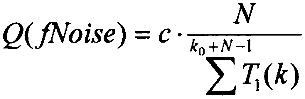
- the noise level integration unit 303 calculates the energy ratio Q between the low frequency subband signal and the noise signal in units of a plurality of subbands based on the time Z frequency grid information 1100. This is more than one subband unit, rather than calculating and signing the energy ratio Q for each subband unit. This is because the number of bits required for the additional signal information 1103 can be reduced by calculating the energy ratio Q. For example, N subbands from subband k to subband k + N— 1
- the additional signal information 1103 is obtained by averaging the noise levels 1101 of N subbands from subband k to subband k + N ⁇ 1.
- fNoise the frequency number of the additional signal information 1103, and c is a constant.
- Patent Document 1 Japanese Translation of Special Publication 2002-536679
- Non-Patent Document 1 "Digital Radio Musice (DRM); System Specification", E TSI, TS 101 980 VI. 1. 1, 5. 2. 6, September 2001
- Non-Patent Document 2 AES (Audio Engineering Society) Convention Paper 55 53 ", 112th AES Convention, May 2002
- Non-Patent Document 3 "Enhanced aacPlus general audio codec; Enhanced aacPl us encoder SBR part", 3GPP, TS 26. 404 V6. 0. 0, September 2004 Disclosure of Invention
- the conventional additional signal information calculation method averages the noise level calculated independently for each subband, the perceptual priority of the subband is not considered. Therefore, the noise level of the sub-bands that are important to the auditory sense depends on the importance of the additional signal information.
- the high-quality audio signal encoding device cannot be realized.
- the method of calculating the additional signal information using the spectrum envelope has a problem that the amount of calculation increases because high resolution frequency analysis and smoothing processing are required.
- the noise level varies greatly depending on the level of smoothness, and it is difficult to optimize the level of smoothing.
- the present invention was invented in view of the above problems, and its purpose is to reduce the amount of additional signal information that reflects the noise level of an audibly important subband according to the degree of importance.
- the object is to provide a technique relating to a high-quality audio signal code that can be calculated in quantity.
- a first invention for solving the above-described problem is an input signal dividing unit for extracting a high frequency signal from an input signal, and generating a first high frequency component information by extracting a spectrum of the high frequency signal.
- a first high-frequency component encoding unit ; a noise level calculation unit that obtains the noise level of the high-frequency signal by reflecting the importance of each frequency component; and second high-frequency component information using the noise level.
- a second invention that solves the above-described problem is an input signal dividing unit that extracts a high-frequency signal from an input signal, and generates a first high-frequency component information by extracting a spectrum of the high-frequency signal.
- a first high-frequency component encoding unit; a noise level calculation unit that calculates a noise level using the high-frequency signal; a correction coefficient calculation unit that calculates a correction coefficient using the high-frequency signal; and the correction A noise level correction unit that corrects the noise level using a coefficient to obtain a corrected noise level; and a second high frequency component encoding unit that generates second high frequency component information using the corrected noise level;
- An audio encoding device comprising: a bit stream multiplexing unit that multiplexes the first high frequency component information and the second high frequency component information and outputs a multiplexed bit stream. It is.
- a third invention for solving the above-described problem is the correction coefficient calculation according to the second invention.
- the unit calculates a correction coefficient that reflects the importance of each frequency component of the high frequency signal.
- the correction coefficient calculation unit calculates energy for each frequency band of the high-frequency signal, and based on the energy for each frequency band. A correction coefficient is calculated.
- a fifth invention for solving the above-mentioned problems is characterized in that, in the second or third invention, the correction coefficient calculation unit calculates a correction coefficient having a small value at a high frequency. To do.
- a sixth invention that solves the above-described problem is that, in the first invention, at least the noise level calculated by the noise level calculation unit reflecting the importance of each frequency component of the high-frequency signal. It is characterized by smoothing in the time direction or frequency direction.
- the correction coefficient calculation unit calculates the frequency component according to each frequency component of the high-frequency signal.
- the correction coefficient is smoothed at least in the time direction or the frequency direction.
- An eighth invention for solving the above-mentioned problem is to extract a high frequency signal from an input signal, extract a spectrum of the high frequency signal to generate first high frequency component information, and The noise level is calculated by reflecting the importance of each frequency component, second high frequency component information is generated from the noise level, and the first high frequency component information and the second high frequency component information are generated. And an audio coding method characterized by outputting a multiplexed bit stream. It is.
- a ninth invention for solving the above-described problem is to extract a high frequency signal from an input signal, extract a spectrum of the high frequency signal to generate first high frequency component information, and The noise level is obtained using the high frequency signal, the correction coefficient is obtained using the high frequency signal, the noise level is corrected using the correction coefficient to obtain the correction noise level, and the second high noise is obtained using the correction noise level.
- An audio coding method characterized by generating band component information, multiplexing the first high band component information and the second high band component information, and outputting a multiplexed bit stream.
- a tenth invention for solving the above-mentioned problems is the above-mentioned eighth invention, wherein the correction coefficient is When obtaining the correction coefficient, a correction coefficient is obtained corresponding to the auditory importance corresponding to each frequency component of the high frequency signal.
- a twelfth invention for solving the above-mentioned problems is characterized in that, in the above-mentioned eighth or ninth invention, when obtaining the correction coefficient, a correction coefficient having a small value at a high frequency is calculated. To do.
- the eighth invention at the time of obtaining the noise level, at least a noise level obtained by reflecting importance of each frequency component of the high frequency signal is used. It is characterized by smoothing in the time direction or frequency direction.
- the correction coefficient when the correction coefficient is obtained, the correction coefficient is determined according to each frequency component of the high frequency signal.
- the calculated correction coefficient is smoothed at least in the time direction or frequency direction.
- a fifteenth aspect of the present invention for solving the above-described problem is a process of extracting a high frequency signal from an input signal, a process of extracting a spectrum of the high frequency signal and generating first high frequency component information, Processing for obtaining the noise level of the high frequency signal by reflecting the importance of each frequency component, processing for generating second high frequency component information using the noise level, and the first high frequency component information
- the present invention is configured to calculate a correction coefficient corresponding to auditory importance using a high frequency sub-band signal, correct a noise level, and generate additional signal information. It is possible to accurately reflect the noise level of a sub-band that is important perceptually. For this reason, a high-quality audio encoding device can be realized.
- the invention's effect it is possible to calculate a correction coefficient based on the perceptual importance of the input signal and correct the noise level of each subband.
- the correction coefficient calculation of the present invention performs frequency analysis with normal resolution, the amount of computation required for high-resolution frequency analysis is reduced, and subband noise that reflects auditory importance is reflected. You can ask for the level. As a result, a high-quality audio encoding device can be realized.
- FIG. 1 is a block diagram showing the configuration of the best mode for carrying out the first invention of the present invention.
- FIG. 2 is an explanatory diagram showing an operation concept of a correction coefficient calculation unit in the present invention.
- FIG. 3 is a block diagram showing a configuration of an input signal dividing unit.
- FIG. 4 is a block diagram showing the configuration of the best mode for carrying out the second invention of the present invention.
- FIG. 5 is a block diagram showing the configuration of the best mode for carrying out the third invention of the present invention.
- FIG. 6 is a block diagram showing a band extension code decoding apparatus.
- FIG. 7 is a block diagram showing a configuration of a high frequency component code key unit.
- an audio encoding device includes an input signal dividing unit 100, a low frequency component encoding unit 101, a time Z frequency grid generating unit 300, a spectrum envelope.
- the high frequency component code key unit 102 and the high frequency component code key unit 500 are different. Comparing these components in more detail using FIG. 1 and FIG. 7, a correction coefficient calculation unit 400 and a noise level correction unit 401 are added to the high frequency component code unit 500, and the noise level integration unit 300 is replaced by the noise level integration unit 402.
- the correction coefficient calculation unit 400, the noise level correction unit 401, and the noise level integration unit 402 will be described.
- the time Z frequency grid information 1100 obtained by grouping a plurality of subband signals in the time and frequency directions in the time Z frequency grid generation unit 300 using the high frequency subband signal 1001 This is transmitted to the correction coefficient calculation unit 400.
- the correction coefficient calculation unit 400 calculates the perceptual importance of each subband using the high frequency subband signal 1001 and the time Z frequency grid information 1100, and calculates the correction coefficient 1200 of each subband to the noise level correction unit 401. Communicate to.
- the noise level 1101 of each subband calculated by the noise level calculation unit 302 using the high frequency subband signal 1001 is also transmitted.
- the noise level correction unit 401 corrects the noise level 1101 of each subband based on the correction coefficient 1200, and outputs the corrected noise level 1201 to the noise level integration unit 402.
- Noise level integration section 402 calculates an average value of corrected noise levels 1103 in a plurality of subbands based on time Z frequency grid information 1100.
- the energy ratio of the noise component is calculated in units of time Z frequency grid and output as additional signal information 1103.
- FIG. 2 shows a part of the spectrum when the input signal 1000 is subjected to frequency analysis, where the horizontal axis represents frequency and the vertical axis represents energy.
- N subbands from subband k to subband k + N— 1 are paired.
- the noise component energy ratio Q in region 2 must be reflected in the additional signal information 1103 in accordance with the importance of region 2. In order to do so, it is necessary to calculate the listening and emotional importance of each subband.
- the correction coefficient 1200 representing the perceptual importance of each subband can be calculated according to the energy of the high frequency subband signal 1001, for example.
- Subband k to subband k
- the correction coefficient a (k) for subband k can be expressed by the following equation, for example: .
- E represents the energy of each subband.
- the energy of each subband may be calculated for each time grid included in the time Z frequency grid information 1100, or may be calculated using subband signals included in a plurality of time grids.
- the energy of the high frequency sub-band signal 1001 is used as it is, but the energy of the sub-band signal 1101 may be corrected.
- the energy of the sub-band signal can be used for calculating the force correction coefficient in a logarithm rather than using it as it is.
- the correction coefficient may be calculated by positively using auditory characteristics. For example, simultaneous masking that makes it impossible to perceive small sounds that are present simultaneously with loud sounds, It is also possible to calculate a correction coefficient that takes into account the effect of the continuous masking that occurs. Sounds smaller than the masking threshold cannot be perceived. Therefore, the correction coefficient corresponding to the auditory importance can be calculated by relatively reducing the correction coefficient of the subband that can be ignored for auditory perception. Conversely, the correction coefficient for subbands larger than the masking threshold may be relatively large.
- the noise level correction unit 401 corrects the noise level 1101 of each subband calculated by the noise level calculation unit based on the correction coefficient 1200 calculated by the correction coefficient calculation unit, and the corrected noise level 1201 is input to the noise level integration unit 303. Output.
- the corrected noise level T (k) is given by
- T (k) a (k) X T (k)
- the result obtained by adding a constant to the product can also be used as a corrected noise level. Furthermore, by defining the correction noise level as an arbitrary function of the correction factor 1200 and the noise level 1101.
- the noise level integration unit 402 uses the corrected noise level 1201 to calculate the energy ratio Q of the additional signal for each frequency grid included in the time Z frequency grid information 1100 and outputs it as the attached calorie signal information 1103. For example, from subband k to subband k + N— 1
- the input signal dividing unit 100 can be configured with a subband dividing unit 110 and a subband combining unit 111 as shown in FIG.
- Subband dividing section 110 divides input signal 1000 into N subbands and outputs high frequency subband signal 1001.
- the subband synthesizing unit 111 generates a low frequency signal 1002 by performing subband synthesis using M (MMN) subband signals of the low frequency of the subband signal.
- M M
- the down-sampling filter 112 can be used to down-sample the input signal 1000.
- the down-sampling filter 112 includes a low-pass filter having a pass band corresponding to the band of the low-frequency signal 1002, and performs high-frequency suppression processing using the low-frequency filter before down-sampling processing. Further, as shown in FIG. 3 (c), the input signal 1000 may be output as the low frequency signal 1002 without being processed.
- correction coefficient 1200 corresponding to auditory importance is calculated using high frequency subband signal 1001, noise level 1101 is corrected, and additional signal information 1103 is generated. Therefore, it is possible to accurately reflect the noise level of the sub-band that is important perceptually. As a result, a high-quality audio encoding device can be realized.
- the best mode for carrying out the second invention of the present invention is that an input signal dividing unit 100, a low frequency component encoding unit 101, a time Z frequency grid generating unit 300, a spectral packet, An envelope calculation unit 301, a noise level calculation unit 302, a correction coefficient calculation unit 403, a noise level correction unit 401, a noise level integration unit 402, and a bit stream multiplexing unit 103 are included.
- the correction coefficient calculation unit 400 is simply replaced with the correction coefficient calculation unit 403, and the other Part Are exactly the same. Therefore, the correction coefficient calculation unit 403 will be described in detail.
- the correction coefficient calculation unit 403 calculates a correction coefficient 1202 by a predetermined method based on the time Z frequency grid information 1100 and outputs the correction coefficient 1202 to the noise level correction unit 401.
- the correction coefficient 1202 can be calculated such that the correction coefficient 1202 takes a small value for a high frequency.
- the correspondence relationship between the frequency and the correction coefficient 1202 can be determined to be expressed by a linear function as the simplest example, or may be determined to be expressed by a nonlinear function.
- a high-frequency signal component is often attenuated more than a low-frequency signal component. Therefore, high-quality additional signal information 1103 can be calculated using the above-described method.
- this embodiment uses a correction coefficient 1202 based on the characteristics of a general audio signal, the amount of calculation can be reduced as compared with the first embodiment of the present invention.
- the third embodiment of the present invention is a computer that operates according to program 601 when the above-described first and second embodiments of the present invention are configured with program 601.
- FIG. 5 the third embodiment of the present invention is a computer that operates according to program 601 when the above-described first and second embodiments of the present invention are configured with program 601.
- the program 601 is read into a computer 600 (central processing unit; processor; data processing device) and controls the operation of the computer 600 (central processing unit; processor; data processing device).
- the computer 600 central processing unit; processor; data processing unit
Landscapes
- Engineering & Computer Science (AREA)
- Physics & Mathematics (AREA)
- Computational Linguistics (AREA)
- Signal Processing (AREA)
- Health & Medical Sciences (AREA)
- Audiology, Speech & Language Pathology (AREA)
- Human Computer Interaction (AREA)
- Acoustics & Sound (AREA)
- Multimedia (AREA)
- Quality & Reliability (AREA)
- Spectroscopy & Molecular Physics (AREA)
- Compression, Expansion, Code Conversion, And Decoders (AREA)
Abstract
Description
明 細 書 Specification
オーディオ符号化装置、オーディオ符号化方法およびオーディオ符号化 プログラム Audio encoding apparatus, audio encoding method, and audio encoding program
技術分野 Technical field
[0001] 本発明は、オーディオ符号化装置、オーディオ符号化方法およびオーディオ符号 化プログラムに関し、特に、広帯域なオーディオ信号を少ない情報量で高品質に符 号化するオーディオ符号化装置、オーディオ符号化方法およびオーディオ符号化プ ログラムに関する。 TECHNICAL FIELD [0001] The present invention relates to an audio encoding device, an audio encoding method, and an audio encoding program, and in particular, an audio encoding device and an audio encoding method for encoding a wideband audio signal with a small amount of information and high quality. And audio encoding program.
背景技術 Background art
[0002] 一般的な音響信号を、少な!、情報量で符号化でき、かつ高品質な再生信号を得ら れる技術として、帯域分割符号ィ匕を利用する方法が広く知られている。このような帯 域分割を利用した符号ィ匕の代表例としては、 ISOZIECの国際標準方式である MP EG - 2 AAC (Advanced Audio Coding)があり、 96kbps程度のビットレートに おいて、 16kHz以上の広帯域ステレオ信号を高品質に符号ィ匕することが可能である [0002] As a technique for encoding a general acoustic signal with a small amount of information and obtaining a high-quality reproduction signal, a method using a band division code is widely known. A typical example of a code that uses such a band division is MP EG-2 AAC (Advanced Audio Coding), which is an international standard of ISOZIEC. At a bit rate of about 96 kbps, 16 kHz or more. It is possible to encode wideband stereo signals with high quality
[0003] し力しながら、ビットレートを例えば 48kbps程度に低下させた場合、高品質に符号 化できる帯域は 10kHz程度以下となり、主観的には高域信号成分に不足を感じる音 となる。このような帯域制限による音質劣化を補償する方法としては、たとえば、非特 許文献 1に記載がある、 SBR (Spectral Band Replication)と呼ばれる技術があ る。同様の技術は、例えば、非特許文献 2においても開示されている。 [0003] However, when the bit rate is reduced to, for example, about 48 kbps, the band that can be encoded with high quality is about 10 kHz or less, and it becomes a sound that subjectively feels that the high-frequency signal component is insufficient. As a method for compensating for such sound quality degradation due to band limitation, for example, there is a technique called SBR (Spectral Band Replication) described in Non-Patent Document 1. A similar technique is also disclosed in Non-Patent Document 2, for example.
[0004] SBRは、 AAC等のオーディオ符号ィ匕処理、もしくはそれに準じる帯域制限処理に よって失われる高!ヽ周波数帯域の信号 (高域成分)を補償することを目的としており、 SBRによって補償される帯域よりも低 、周波数帯域の信号 (低域成分)につ 、ては、 他の手段を用いて伝送する必要がある。 SBRによって符号ィ匕された情報には、他の 手段を用いて伝送される低域成分を基に、擬似的な高域成分を生成するための情 報が含まれており、前記低域成分に擬似的な高域成分を加算することにより、帯域制 限による音質劣化を補償する。 [0005] 以下、図 6を参照しながら、 SBRの動作を詳しく説明する。図 6は、 SBRを用いた帯 域拡張符号化復号装置の一例を示す図である。符号化側は、入力信号分割部 100、 低域成分符号化部 101、高域成分符号化部 102、ビットストリーム多重化部 103から構 成され、復号側は、ビットストリーム分離部 200、低域成分復号部 201、サブバンド分割 部 202、帯域拡張部 203、サブバンド合成部 204から構成される。 [0004] SBR is intended to compensate for high frequency band signals (high frequency components) that are lost by audio code processing such as AAC, or band-limiting processing based on it, and is compensated by SBR. For signals in the frequency band lower than the band to be transmitted (low frequency components), it is necessary to transmit them using other means. The information encoded by the SBR includes information for generating a pseudo high-frequency component based on the low-frequency component transmitted using other means. By adding a pseudo high-frequency component to, the sound quality degradation due to band limitation is compensated. [0005] Hereinafter, the operation of the SBR will be described in detail with reference to FIG. FIG. 6 is a diagram illustrating an example of a band extension coding / decoding device using SBR. The encoding side is composed of an input signal dividing unit 100, a low frequency component encoding unit 101, a high frequency component encoding unit 102, and a bit stream multiplexing unit 103, and the decoding side is a bit stream separating unit 200, a low frequency component A component decoding unit 201, a subband division unit 202, a band extension unit 203, and a subband synthesis unit 204 are configured.
[0006] 符号化側では、入力信号分割部 100が、入力信号 1000を分析し、複数の高周波数 帯域に分割した高域サブバンド信号 1001と低域成分を含む低域信号 1002を出力す る。低域信号 1002は上述の AAC等の符号化方式を用いて低域成分符号化部 101に より低域成分情報 1004に符号化され、ビットストリーム多重化部 103に伝達される。ま た、高域成分符号化部 102は、高域サブバンド信号 1001から高域エネルギ情報 1102 及び付加信号情報 1103を抽出し、ビットストリーム多重化部 103に伝達する。ビットスト リーム多重化部 103は低域成分情報 1004と高域エネルギ情報 1102及び付加信号情 報 1103から構成される高域成分情報を多重化し、多重化ビットストリーム 1005として 出力する。 [0006] On the encoding side, the input signal dividing unit 100 analyzes the input signal 1000 and outputs a high frequency sub-band signal 1001 divided into a plurality of high frequency bands and a low frequency signal 1002 including a low frequency component. . The low-frequency signal 1002 is encoded into the low-frequency component information 1004 by the low-frequency component encoding unit 101 using the above-described encoding method such as AAC, and transmitted to the bit stream multiplexing unit 103. Also, the high frequency component encoding unit 102 extracts the high frequency energy information 1102 and the additional signal information 1103 from the high frequency subband signal 1001 and transmits them to the bit stream multiplexing unit 103. The bitstream multiplexing unit 103 multiplexes the high frequency component information composed of the low frequency component information 1004, the high frequency energy information 1102, and the additional signal information 1103, and outputs the multiplexed bit stream 1005.
[0007] ここで、高域エネルギ情報 1102及び付加信号情報 1103は、例えば、サブバンド毎 にフレーム単位で算出される。入力信号 1000の時間及び周波数方向の特性を考慮 して、時間方向にはフレームをさらに細分割した時間単位で、周波数方向には複数 のサブバンドをまとめたバンド単位で算出しても良い。高域エネルギ情報 1102及び付 加信号情報 1103を、時間方向のフレームをさらに細分割した時間単位で算出する場 合には、高域サブバンド信号 1001の時間変化をより詳細に表すことができる。高域ェ ネルギ情報 1102及び付加信号情報 1103を、複数のサブバンドをまとめたバンド単位 で算出する場合には、高域エネルギ情報 1102及び付加信号情報 1103を符号ィ匕する ために必要な総ビット数を削減できる。高域エネルギ情報 1102及び付加信号情報 11 03の算出に利用する時間及び周波数方向の分割単位を時間周波数グリッドと呼び、 その情報は高域エネルギ情報 1102及び付加信号情報 1103に含まれる。 [0007] Here, the high frequency energy information 1102 and the additional signal information 1103 are calculated in units of frames for each subband, for example. In consideration of the characteristics of the input signal 1000 in the time and frequency directions, it may be calculated in units of time obtained by further subdividing the frame in the time direction and in units of bands in which a plurality of subbands are combined in the frequency direction. When the high-frequency energy information 1102 and the additional signal information 1103 are calculated in time units obtained by further subdividing the frame in the time direction, the time change of the high-frequency subband signal 1001 can be expressed in more detail. When the high frequency energy information 1102 and the additional signal information 1103 are calculated in units of bands in which a plurality of subbands are combined, the total bits required to code the high frequency energy information 1102 and the additional signal information 1103 The number can be reduced. The division unit in the time and frequency direction used for calculating the high-frequency energy information 1102 and the additional signal information 1103 is called a time-frequency grid, and the information is included in the high-frequency energy information 1102 and the additional signal information 1103.
[0008] このような構成では、高域エネルギ情報 1102及び付加信号情報 1103に含まれる情 報が、高域エネルギ情報と付加信号情報だけとなる。このため、狭帯域信号の波形 情報及びスペクトル情報を含む低域成分情報と比較して、少な 、情報量 (総ビット数) しか必要としない。したがって、広帯域信号の低ビットレート符号ィ匕に適している。 In such a configuration, the information included in the high frequency energy information 1102 and the additional signal information 1103 is only the high frequency energy information and the additional signal information. For this reason, the amount of information (total number of bits) is small compared to low band component information including waveform information and spectrum information of narrowband signals. I only need it. Therefore, it is suitable for low bit rate codes for wideband signals.
[0009] 復号側では、多重化ビットストリーム 1005がビットストリーム分離部 200において、低 域成分情報 1007、高域エネルギ情報 1105及び付加信号情報 1106に分離される。低 域成分情報 1007は、例えば AAC等の符号化方式を用いて符号化された情報であり 、低域成分復号部 201において復号されて、低域成分を表す狭帯域信号 1008を生 成する。狭帯域信号 1008は、サブバンド分割部 202において低域サブバンド信号 100 9に分割され、帯域拡張部 203に入力される。低域サブバンド信号 1009は、同時にサ ブバンド合成部 204にも供給される。帯域拡張部 203は、低域サブバンド信号 1009を 高域のサブバンドに複写することによって、帯域制限によって失われた高域成分を再 生する。 On the decoding side, the multiplexed bit stream 1005 is separated into low-frequency component information 1007, high-frequency energy information 1105, and additional signal information 1106 by the bit stream separation unit 200. The low-frequency component information 1007 is information encoded using an encoding method such as AAC, for example, and is decoded by the low-frequency component decoding unit 201 to generate a narrowband signal 1008 representing the low-frequency component. Narrowband signal 1008 is divided into lowband subband signal 1009 by subband division section 202 and input to band extension section 203. The low-frequency subband signal 1009 is also supplied to the subband synthesis unit 204 at the same time. The band extension unit 203 reproduces the high frequency component lost due to the band limitation by copying the low frequency subband signal 1009 to the high frequency subband.
[0010] 帯域拡張部 203に入力される高域エネルギ情報 1105には、再生される高域サブバ ンドのエネルギ情報が含まれる。高域エネルギ情報 1105を用いて低域サブバンド信 号 1009のエネルギを調整した後、高域成分として利用する。また、帯域拡張部 203は 、付加信号情報 1106に含まれる付加信号情報にしたがって付加信号を生成する。こ こで、生成される付加信号としては、正弦波トーン信号やノイズ信号が用いられる。前 記エネルギ調整後の高域成分に前記付加信号を加算して、高域サブバンド信号 101 [0010] The high band energy information 1105 input to the band extension unit 203 includes energy information of the high band subband to be reproduced. After adjusting the energy of the low frequency subband signal 1009 using the high frequency energy information 1105, it is used as the high frequency component. Band extension section 203 generates an additional signal in accordance with additional signal information included in additional signal information 1106. Here, a sine wave tone signal or a noise signal is used as the generated additional signal. The additional signal is added to the energy-adjusted high frequency component to obtain a high frequency sub-band signal 101.
0としてサブバンド合成部 204に供給する。サブバンド合成部 204は、サブバンド分割 部 202から供給された低域サブバンド信号 1009と帯域拡張部 203から供給された高域 サブバンド信号 1010を帯域合成し、出力信号 1011を生成する。 It is supplied as 0 to the subband synthesis unit 204. Subband synthesizing section 204 band-synthesizes low band subband signal 1009 supplied from subband dividing section 202 and high band subband signal 1010 supplied from band extending section 203 to generate output signal 1011.
[0011] ここで、帯域拡張部 203におけるエネルギ調整の動作について詳細に説明する。高 域サブバンド信号 1010のエネルギが高域エネルギ情報 1105の表すエネルギ値(以 下、目標エネルギとする)となるように、複写された低域サブバンド信号 1009と付加信 号の利得を調整して力もエネルギ調整後の高域成分に加算して、高域サブバンド信 号 1010を生成する。複写された低域サブバンド信号 1009と付加信号の利得は、例え ば、次の手順で決定することができる。 Here, the operation of energy adjustment in band extension section 203 will be described in detail. The gains of the copied low frequency subband signal 1009 and the additional signal are adjusted so that the energy of the high frequency subband signal 1010 becomes the energy value represented by the high frequency energy information 1105 (hereinafter referred to as target energy). The high frequency subband signal 1010 is generated by adding the force to the high frequency component after energy adjustment. The gain of the copied low-frequency subband signal 1009 and the additional signal can be determined, for example, by the following procedure.
[0012] まず、複写された低域サブバンド信号 1009と付加信号とのうちいずれかを高域サブ バンド信号 1010の主成分とし、他方を副成分とする。低域サブバンド信号 1009を主成 分、付加信号を副成分とする場合は、次式で利得を決定する。 G =sqrt (R/E/ (l + Q) ) [0012] First, one of the copied low-frequency subband signal 1009 and the additional signal is set as a main component of the high-frequency subband signal 1010, and the other as a subcomponent. When the low frequency subband signal 1009 is the main component and the additional signal is the subcomponent, the gain is determined by the following equation. G = sqrt (R / E / (l + Q))
main main
G =sqrt (R* QZN (l + Q) ) G = sqrt (R * QZN (l + Q))
sub sub
ここで、 G は主成分の振幅調整用利得、 G は副成分の振幅調整用利得、 Eと N Where G is the main component amplitude adjustment gain, G is the sub component amplitude adjustment gain, and E and N
mam sub mam sub
は、それぞれ、低域サブバンド信号 1009と付加信号のエネルギを表す。付加信号の エネルギが 1に正規ィ匕されている場合は、 N= lとする。また、 Rは高域サブバンド信 号 1010の目標エネルギ、 Qは主成分と副成分のエネルギ比を表し、 Rと Qは高域エネ ルギ情報 1105及び付加信号情報 1106に含まれている。なお、 sqrt(')は平方根を求 める演算子とする。一方、付加信号を主成分、低域サブバンド信号 1009を主成分と する場合は、次式で利得を決定する。 Represent the energies of the low frequency subband signal 1009 and the additional signal, respectively. If the energy of the additional signal is normally set to 1, N = l. R represents the target energy of the high frequency sub-band signal 1010, Q represents the energy ratio of the main component and the sub component, and R and Q are included in the high frequency energy information 1105 and the additional signal information 1106. Note that sqrt (') is an operator for finding the square root. On the other hand, when the additional signal is the main component and the low-frequency subband signal 1009 is the main component, the gain is determined by the following equation.
G =sqrt (R/N/ (l + Q) ) G = sqrt (R / N / (l + Q))
main main
G =sqrt (R* Q/E/ (l + Q) ) G = sqrt (R * Q / E / (l + Q))
sub sub
以上の手続きによって算出した利得を用いて、低域サブバンド信号 1009と付加信号 を重み付け加算し、高域サブバンド信号 1010を算出する。 Using the gain calculated by the above procedure, the low frequency subband signal 1009 and the additional signal are weighted and added to calculate the high frequency subband signal 1010.
[0013] オーディオ信号を低ビットレートで高品質に符号ィ匕するためには、高域成分を少な い情報量に圧縮することが必要である。従って、高域成分符号ィ匕部 102において、正 確な高域エネルギ情報 1102及び付加信号情報 1103を抽出することが重要となる。例 えば、弦楽器など低域成分より高域成分のノイズレベルが高 ヽ信号を符号化する場 合、低域サブバンド信号 1009を高周波数帯域にコピーした信号に適切な大きさのノ ィズ信号を付加することにより品質を向上させることが可能である。適切な大きさのノ ィズ信号を復号側で付加するためには、符号ィ匕側において生成する付加信号情報 1 103に、低域サブバンド信号 1009と付加するノイズ信号の正確なエネルギ比 Qを含む 必要がある。このため、高域成分符号ィ匕部 102において、入力信号における高域成 分のノイズレベルを正確に算出する必要がある。 In order to encode an audio signal with high quality at a low bit rate, it is necessary to compress the high frequency component to a small amount of information. Therefore, it is important to extract accurate high frequency energy information 1102 and additional signal information 1103 in the high frequency component code key unit 102. For example, when encoding a signal with a high-frequency noise level higher than the low-frequency component, such as a stringed musical instrument, a noise signal with an appropriate size for the signal copied from the low-frequency subband signal 1009 to the high-frequency band. It is possible to improve the quality by adding. In order to add a noise signal of an appropriate size on the decoding side, an accurate energy ratio Q between the low-frequency subband signal 1009 and the noise signal to be added is added to the additional signal information 1103 generated on the code side. Must be included. For this reason, the high frequency component code key unit 102 needs to accurately calculate the noise level of the high frequency component in the input signal.
[0014] 高域成分のノイズレベルを算出する高域成分符号ィ匕部 102の第一の従来例が、非 特許文献 3に開示されている。図 7に示す高域成分符号ィ匕部は、時間 Z周波数ダリ ッド生成部 300、スペクトル包絡算出部 301、ノイズレベル算出部 302、ノイズレベル統 合部 303から構成される。 [0014] Non-Patent Document 3 discloses a first conventional example of a high-frequency component code key unit 102 that calculates a noise level of a high-frequency component. 7 includes a time Z frequency dial generation unit 300, a spectrum envelope calculation unit 301, a noise level calculation unit 302, and a noise level integration unit 303.
[0015] 時間 Z周波数グリッド生成部 300は、高域サブバンド信号 1001を用いて、時間及び 周波数方向の複数のサブバンド信号をグループィ匕し、時間 Z周波数グリッド情報 no[0015] The time Z frequency grid generation unit 300 uses the high frequency subband signal 1001 to Group multiple subband signals in the frequency direction and time Z frequency grid information no
0を生成する。スペクトル包絡算出部 301は、時間 Z周波数グリッド単位で高域サブバ ンド信号の目標エネルギ Rを抽出し、高域エネルギ情報 1102としてビットストリーム多 重化部 103に供給する。ノイズレベル算出部 302は、各サブバンド単位で、サブバンド 信号に含まれるノイズ成分の割合をノイズレベル 1101として出力する。ノイズレベル統 合部 303は複数のサブバンドにおける前記ノイズレベルの平均値を用いて、時間 Z 周波数グリッド単位で前述のエネルギ比 Qを表す付加信号情報 1103を求め、ビットス トリーム多重化部 103に供給する。 Generate 0. The spectrum envelope calculation unit 301 extracts the target energy R of the high-frequency subband signal in units of time Z frequency grids, and supplies the target energy R to the bitstream multiplexing unit 103 as high-frequency energy information 1102. The noise level calculation unit 302 outputs the ratio of the noise component included in the subband signal as the noise level 1101 for each subband. The noise level integration unit 303 uses the average value of the noise levels in a plurality of subbands to obtain additional signal information 1103 representing the energy ratio Q in units of time Z frequency grids, and supplies the additional signal information 1103 to the bit stream multiplexing unit 103. To do.
[0016] ノイズレベル算出部 302におけるノイズレベル 1101の算出方法としては、予測残差 を用いた方法が知られており、サブバンド kのノイズレベル T(k)は、次の式に従って 算出できる。 [0016] As a method of calculating the noise level 1101 in the noise level calculation unit 302, a method using a prediction residual is known, and the noise level T (k) of subband k can be calculated according to the following equation.
[数 1] [Number 1]

[0017] ノイズレベル統合部 303は、時間 Z周波数グリッド情報 1100に基づき、複数のサブ バンド単位で、低域サブバンド信号とノイズ信号のエネルギ比 Qを算出する。これは、 各サブバンド単位でエネルギ比 Qを算出し符号ィ匕するよりも、複数のサブバンド単位 でエネルギ比 Qを算出したほうが、付加信号情報 1103に必要なビット数を削減できる ためである。例えば、サブバンド kからサブバンド k +N— 1までの Nサブバンドを同 The noise level integration unit 303 calculates the energy ratio Q between the low frequency subband signal and the noise signal in units of a plurality of subbands based on the time Z frequency grid information 1100. This is more than one subband unit, rather than calculating and signing the energy ratio Q for each subband unit. This is because the number of bits required for the additional signal information 1103 can be reduced by calculating the energy ratio Q. For example, N subbands from subband k to subband k + N— 1
0 0 0 0
一のエネルギ比 Q (fNoise)で表す場合を考える。付加信号情報 1103は、サブバンド kからサブバンド k +N— 1まで Nサブバンドのノイズレベル 1101を平均化することに Consider the case where the energy ratio is expressed as Q (fNoise). The additional signal information 1103 is obtained by averaging the noise levels 1101 of N subbands from subband k to subband k + N−1.
0 0 0 0
より算出される。 Q (fNoise)は、以下の式で表される。 It is calculated from. Q (fNoise) is expressed by the following equation.
[数 2] [Equation 2]
p=k{ ここで、 fNoiseは付加信号情報 1103の周波数番号を表し、 cは定数である。 p = k { where fNoise represents the frequency number of the additional signal information 1103, and c is a constant.
[0018] 高域成分のノイズレベルを算出する高域成分符号ィ匕部 102の第二の従来例として、 特許文献 1で開示されている方法がある。第二の従来例では、入力信号に高分解能 FFTを適用して算出されるスペクトル包絡の最大値と最小値の差を計算し、時間と周 波数で平滑ィ匕した結果をノイズレベルとして 、る。 特許文献 1:特表 2002— 536679号公報 [0018] As a second conventional example of the high frequency component code key unit 102 for calculating the noise level of the high frequency component, there is a method disclosed in Patent Document 1. In the second conventional example, the difference between the maximum and minimum values of the spectral envelope calculated by applying a high-resolution FFT to the input signal is calculated, and the result of smoothing with the time and frequency is used as the noise level. . Patent Document 1: Japanese Translation of Special Publication 2002-536679
非特許文献 1: "Digital Radio Mondiale (DRM); System Specification", E TSI, TS 101 980 VI. 1. 1, 5. 2. 6節, 2001年 9月 Non-Patent Document 1: "Digital Radio Mondiale (DRM); System Specification", E TSI, TS 101 980 VI. 1. 1, 5. 2. 6, September 2001
非特許文献 2 : AES (Audio Engineering Society) Convention Paper 55 53", 112th AES Convention, 2002年 5月 Non-Patent Document 2: AES (Audio Engineering Society) Convention Paper 55 53 ", 112th AES Convention, May 2002
非特許文献 3 : "Enhanced aacPlus general audio codec; Enhanced aacPl us encoder SBR part", 3GPP, TS 26. 404 V6. 0. 0, 2004年 9月 発明の開示 Non-Patent Document 3: "Enhanced aacPlus general audio codec; Enhanced aacPl us encoder SBR part", 3GPP, TS 26. 404 V6. 0. 0, September 2004 Disclosure of Invention
発明が解決しょうとする課題 Problems to be solved by the invention
[0019] 従来の付加信号情報算出方法は、各サブバンド単位で独立に算出したノイズレべ ルを平均化しているため、サブバンドの聴感的な優先度が考慮されていない。そのた め、聴感的に重要なサブバンドのノイズレベルがその重要度に応じて付加信号情報 に反映されず、高品質なオーディオ信号符号化装置を実現できな!ヽと ヽぅ問題があ つた o [0019] Since the conventional additional signal information calculation method averages the noise level calculated independently for each subband, the perceptual priority of the subband is not considered. Therefore, the noise level of the sub-bands that are important to the auditory sense depends on the importance of the additional signal information. The high-quality audio signal encoding device cannot be realized.
[0020] また、スペクトル包絡を用いて付加信号情報を算出する方法は、高分解能な周波 数解析や平滑ィ匕処理を必要とするために、演算量が増加するという問題があった。さ らに、平滑ィ匕の程度によってノイズレベルの値が大きく異なり、平滑化程度の最適化 が困難であるという問題もあった。 [0020] Further, the method of calculating the additional signal information using the spectrum envelope has a problem that the amount of calculation increases because high resolution frequency analysis and smoothing processing are required. In addition, the noise level varies greatly depending on the level of smoothness, and it is difficult to optimize the level of smoothing.
[0021] そこで、本発明は上記課題に鑑みて発明されたものであって、その目的は、聴感的 に重要なサブバンドのノイズレベルを重要度に応じて反映した付加信号情報を少な い演算量で算出することのできる、高品質なオーディオ信号符号ィ匕に関する技術を 提供することにある。 [0021] Therefore, the present invention was invented in view of the above problems, and its purpose is to reduce the amount of additional signal information that reflects the noise level of an audibly important subband according to the degree of importance. The object is to provide a technique relating to a high-quality audio signal code that can be calculated in quantity.
課題を解決するための手段 Means for solving the problem
[0022] 上記課題を解決する第 1の発明は、入力信号から高域信号を抽出する入力信号分 割部と、前記高域信号のスペクトルを抽出して第一の高域成分情報を生成する第一 の高域成分符号化部と、前記高域信号のノイズレベルを各周波数成分の重要度を 反映させて求めるノイズレベル算出部と、前記ノイズレベルを用いて第二の高域成分 情報を生成する第二の高域成分符号化部と、前記第一の高域成分情報と前記第二 の高域成分情報とを多重化して、多重化ビットストリームを出力するビットストリーム多 重化部と、を有することを特徴とするオーディオ符号ィ匕装置である。 [0022] A first invention for solving the above-described problem is an input signal dividing unit for extracting a high frequency signal from an input signal, and generating a first high frequency component information by extracting a spectrum of the high frequency signal. A first high-frequency component encoding unit; a noise level calculation unit that obtains the noise level of the high-frequency signal by reflecting the importance of each frequency component; and second high-frequency component information using the noise level. A second high frequency component encoding unit to be generated; a bit stream multiplexing unit that multiplexes the first high frequency component information and the second high frequency component information and outputs a multiplexed bit stream; And an audio encoding device.
[0023] 上記課題を解決する第 2の発明は、入力信号から高域信号を抽出する入力信号分 割部と、前記高域信号のスペクトルを抽出して第一の高域成分情報を生成する第一 の高域成分符号化部と、前記高域信号を用いてノイズレベルを算出するノイズレべ ル算出部と、前記高域信号を用いて補正係数を算出する補正係数算出部と、前記 補正係数を用いて前記ノイズレベルを補正し、補正ノイズレベルを求めるノイズレべ ル補正部と、前記補正ノイズレベルを用いて第二の高域成分情報を生成する第二の 高域成分符号化部と、前記第一の高域成分情報と前記第二の高域成分情報とを多 重化して、多重化ビットストリームを出力するビットストリーム多重化部と、を有すること を特徴とするオーディオ符号化装置である。 [0023] A second invention that solves the above-described problem is an input signal dividing unit that extracts a high-frequency signal from an input signal, and generates a first high-frequency component information by extracting a spectrum of the high-frequency signal. A first high-frequency component encoding unit; a noise level calculation unit that calculates a noise level using the high-frequency signal; a correction coefficient calculation unit that calculates a correction coefficient using the high-frequency signal; and the correction A noise level correction unit that corrects the noise level using a coefficient to obtain a corrected noise level; and a second high frequency component encoding unit that generates second high frequency component information using the corrected noise level; An audio encoding device comprising: a bit stream multiplexing unit that multiplexes the first high frequency component information and the second high frequency component information and outputs a multiplexed bit stream. It is.
[0024] 上記課題を解決する第 3の発明は、上記第 2の発明において、前記補正係数算出 部が、前記高域信号の各周波数成分の重要度を反映した補正係数を算出すること を特徴とする。 [0024] A third invention for solving the above-described problem is the correction coefficient calculation according to the second invention. The unit calculates a correction coefficient that reflects the importance of each frequency component of the high frequency signal.
[0025] 上記課題を解決する第 4の発明は、上記第 2の発明において、前記補正係数算出 部が、前記高域信号の周波数帯域別エネルギを算出し、前記周波数帯域別エネル ギに基づいて補正係数を算出することを特徴とする。 [0025] According to a fourth invention for solving the above-mentioned problem, in the second invention, the correction coefficient calculation unit calculates energy for each frequency band of the high-frequency signal, and based on the energy for each frequency band. A correction coefficient is calculated.
[0026] 上記課題を解決する第 5の発明は、上記第 2又は第 3の発明において、前記補正 係数算出部が、高い周波数で小さい値を有するような補正係数を算出することを特 徴とする。 [0026] A fifth invention for solving the above-mentioned problems is characterized in that, in the second or third invention, the correction coefficient calculation unit calculates a correction coefficient having a small value at a high frequency. To do.
[0027] 上記課題を解決する第 6の発明は、上記第 1の発明において、前記ノイズレベル算 出部が、前記高域信号の各周波数成分の重要度を反映させて求めたノイズレベルを 少なくとも時間方向または周波数方向に平滑ィ匕することを特徴とする。 [0027] A sixth invention that solves the above-described problem is that, in the first invention, at least the noise level calculated by the noise level calculation unit reflecting the importance of each frequency component of the high-frequency signal. It is characterized by smoothing in the time direction or frequency direction.
[0028] 上記課題を解決する第 7の発明は、上記第 2から第 5の 、ずれかの発明にお 、て、 前記補正係数算出部が、前記高域信号の各周波数成分に応じて算出した補正係数 を少なくとも時間方向または周波数方向に平滑ィ匕することを特徴とする。 [0028] In a seventh invention that solves the above-described problem, in the second to fifth inventions, the correction coefficient calculation unit calculates the frequency component according to each frequency component of the high-frequency signal. The correction coefficient is smoothed at least in the time direction or the frequency direction.
[0029] 上記課題を解決する第 8の発明は、入力信号から高域信号を抽出し、前記高域信 号のスペクトルを抽出して第一の高域成分情報を生成し、前記高域信号のノイズレ ベルを各周波数成分の重要度を反映させて求め、前記ノイズレベルカゝら第二の高域 成分情報を生成し、前記第一の高域成分情報と前記第二の高域成分情報とを多重 化して、多重化ビットストリームを出力することを特徴とするオーディオ符号ィ匕方法。 である。 [0029] An eighth invention for solving the above-mentioned problem is to extract a high frequency signal from an input signal, extract a spectrum of the high frequency signal to generate first high frequency component information, and The noise level is calculated by reflecting the importance of each frequency component, second high frequency component information is generated from the noise level, and the first high frequency component information and the second high frequency component information are generated. And an audio coding method characterized by outputting a multiplexed bit stream. It is.
[0030] 上記課題を解決する第 9の発明は、入力信号から高域信号を抽出し、前記高域信 号のスペクトルを抽出して第一の高域成分情報を生成し、前記高域信号を用いてノ ィズレベルを求め、前記高域信号を用いて補正係数を求め、前記補正係数を用いて 前記ノイズレベルを補正して補正ノイズレベルを求め、前記補正ノイズレベルを用い て第二の高域成分情報を生成し、前記第一の高域成分情報と前記第二の高域成分 情報とを多重化して、多重化ビットストリームを出力することを特徴とするオーディオ符 号化方法である。 [0030] A ninth invention for solving the above-described problem is to extract a high frequency signal from an input signal, extract a spectrum of the high frequency signal to generate first high frequency component information, and The noise level is obtained using the high frequency signal, the correction coefficient is obtained using the high frequency signal, the noise level is corrected using the correction coefficient to obtain the correction noise level, and the second high noise is obtained using the correction noise level. An audio coding method characterized by generating band component information, multiplexing the first high band component information and the second high band component information, and outputting a multiplexed bit stream.
[0031] 上記課題を解決する第 10の発明は、上記第 8の発明において、前記補正係数を 求める際に、前記高域信号の各周波数成分に応じた聴感的な重要度に対応して補 正係数を求めることを特徴とする。 [0031] A tenth invention for solving the above-mentioned problems is the above-mentioned eighth invention, wherein the correction coefficient is When obtaining the correction coefficient, a correction coefficient is obtained corresponding to the auditory importance corresponding to each frequency component of the high frequency signal.
[0032] 上記課題を解決する第 11の発明は、上記第 8の発明において、前記補正係数を 求める際に、前記高域信号の周波数帯域別エネルギを求め、前記周波数帯域別ェ ネルギに基づいて補正係数を求めることを特徴とする。 [0032] In an eleventh invention for solving the above-mentioned problem, in the above-mentioned eighth invention, when obtaining the correction coefficient, energy for each frequency band of the high-frequency signal is obtained, and based on the energy for each frequency band. A correction coefficient is obtained.
[0033] 上記課題を解決する第 12の発明は、上記第 8又は第 9の発明において、前記補正 係数を求める際に、高い周波数で小さい値を有するような補正係数を算出することを 特徴とする。 [0033] A twelfth invention for solving the above-mentioned problems is characterized in that, in the above-mentioned eighth or ninth invention, when obtaining the correction coefficient, a correction coefficient having a small value at a high frequency is calculated. To do.
[0034] 上記課題を解決する第 13の発明は、上記第 8の発明において、前記ノイズレベル を求める際に、前記高域信号の各周波数成分の重要度を反映させて求めたノイズレ ベルを少なくとも時間方向または周波数方向に平滑ィ匕することを特徴とする。 [0034] In a thirteenth invention for solving the above-mentioned problem, in the eighth invention, at the time of obtaining the noise level, at least a noise level obtained by reflecting importance of each frequency component of the high frequency signal is used. It is characterized by smoothing in the time direction or frequency direction.
[0035] 上記課題を解決する第 14の発明は、上記第 9から請求項 11の 、ずれかの発明に おいて、前記補正係数を求める際に、前記高域信号の各周波数成分に応じて算出 した補正係数を少なくとも時間方向または周波数方向に平滑ィ匕することを特徴とする [0035] According to a fourteenth aspect of the present invention for solving the above-mentioned problems, in the invention according to any one of the ninth to eleventh aspects, when the correction coefficient is obtained, the correction coefficient is determined according to each frequency component of the high frequency signal. The calculated correction coefficient is smoothed at least in the time direction or frequency direction.
[0036] 上記課題を解決する第 15の発明は、入力信号から高域信号を抽出する処理と、前 記高域信号のスペクトルを抽出して第一の高域成分情報を生成する処理と、前記高 域信号のノイズレベルを各周波数成分の重要度を反映させて求める処理と、前記ノ ィズレベルを用いて第二の高域成分情報を生成する処理と、前記第一の高域成分 情報と前記第二の高域成分情報とを多重化して、多重化ビットストリームを出力する 処理とをコンピュータに実行させるためのプログラムである。 [0036] A fifteenth aspect of the present invention for solving the above-described problem is a process of extracting a high frequency signal from an input signal, a process of extracting a spectrum of the high frequency signal and generating first high frequency component information, Processing for obtaining the noise level of the high frequency signal by reflecting the importance of each frequency component, processing for generating second high frequency component information using the noise level, and the first high frequency component information A program for causing a computer to execute a process of multiplexing the second high frequency component information and outputting a multiplexed bit stream.
[0037] 本発明は、高域サブバンド信号を用いて、聴感的な重要度に対応した補正係数を 算出し、ノイズレベルを補正し、付加信号情報を生成するように構成されているため、 聴感的に重要なサブバンドのノイズレベルを正確に反映することができる。このため、 高品質のオーディオ符号ィ匕装置を実現することができる。 [0037] The present invention is configured to calculate a correction coefficient corresponding to auditory importance using a high frequency sub-band signal, correct a noise level, and generate additional signal information. It is possible to accurately reflect the noise level of a sub-band that is important perceptually. For this reason, a high-quality audio encoding device can be realized.
[0038] また、一般的なオーディオ信号の特性に基づく補正係数を用いるようにすれば、更 に演算量を削減することができる。 [0038] If a correction coefficient based on the characteristics of a general audio signal is used, the amount of calculation can be further reduced.
発明の効果 [0039] 本発明によれば、入力信号の聴感的な重要度に基づいた補正係数を算出し、各サ ブバンドのノイズレベルを補正することができる。 The invention's effect [0039] According to the present invention, it is possible to calculate a correction coefficient based on the perceptual importance of the input signal and correct the noise level of each subband.
[0040] また、本発明の補正係数算出では、通常分解能の周波数解析を行うので、高分解 能な周波数解析に必要な演算量を削減しつつ、聴感的な重要度を反映したサブバ ンドのノイズレベルを求めることができる。その結果、高品質なオーディオ符号化装置 を実現することが可能となる。 [0040] In addition, since the correction coefficient calculation of the present invention performs frequency analysis with normal resolution, the amount of computation required for high-resolution frequency analysis is reduced, and subband noise that reflects auditory importance is reflected. You can ask for the level. As a result, a high-quality audio encoding device can be realized.
図面の簡単な説明 Brief Description of Drawings
[0041] [図 1]本発明の第 1の発明を実施するための最良の形態の構成を示すブロック図であ る。 FIG. 1 is a block diagram showing the configuration of the best mode for carrying out the first invention of the present invention.
[図 2]本発明における補正係数算出部の動作概念を示す説明図である。 FIG. 2 is an explanatory diagram showing an operation concept of a correction coefficient calculation unit in the present invention.
[図 3]入力信号分割部の構成を表すブロック図である。 FIG. 3 is a block diagram showing a configuration of an input signal dividing unit.
[図 4]本発明の第 2の発明を実施するための最良の形態の構成を示すブロック図であ る。 FIG. 4 is a block diagram showing the configuration of the best mode for carrying out the second invention of the present invention.
[図 5]本発明の第 3の発明を実施するための最良の形態の構成を示すブロック図であ る。 FIG. 5 is a block diagram showing the configuration of the best mode for carrying out the third invention of the present invention.
[図 6]帯域拡張符号ィ匕復号装置を示すブロック図である。 FIG. 6 is a block diagram showing a band extension code decoding apparatus.
[図 7]高域成分符号ィ匕部の構成を示すブロック図である。 FIG. 7 is a block diagram showing a configuration of a high frequency component code key unit.
符号の説明 Explanation of symbols
[0042] 110000 入力信号分割部 [0042] 110000 Input signal divider
101 低域成分符号化部 101 Low frequency component encoding part
102、 500 高域成分符号化部 102, 500 High-frequency component encoder
103 ビットストリーム多重化部 103 Bitstream multiplexing unit
110、 202 サブバンド分割部 110, 202 subband division
111、 204 サブバンド合成部 111, 204 subband synthesis section
112 ダウンサンプリングフイノレタ 112 Downsampling Finale
200 ビットストリーム分離部 200 bitstream separator
201 低域成分復号部 201 Low-frequency component decoder
203 帯域拡張部 300 時間 Z周波数グリッド生成部 203 Bandwidth extension 300 hours Z frequency grid generator
301 スペクトル包絡算出部 301 Spectral envelope calculator
302 ノイズレベル算出部 302 Noise level calculator
303、 402 ノイズレベル統合部 303, 402 Noise level integration section
400、 403 補正係数算出部 400, 403 correction coefficient calculator
401 ノイズレベル補正部 401 Noise level correction unit
1000 入力信号 1000 input signal
1001 高域サブバンド信号 1001 High frequency sub-band signal
1002 低域信号 1002 Low frequency signal
1004、 1007 低域成分情報 1004, 1007 Low frequency component information
1005 ビットストリーム 1005 bitstream
1008 低域成分復号信号 1008 Low-frequency component decoded signal
1009 低域サブバンド信号 1009 Low frequency subband signal
1010 高域サブバンド信号 1010 High frequency sub-band signal
1011 帯域拡張信号 1011 Band extension signal
1100 時間 Z周波数グリッド情報 1100 hours Z frequency grid information
1101 ノイズレべノレ 1101 Noise level
1102、 1105 高域エネルギ情報 1102, 1105 High energy information
1103、 1106 付加信号情報 1103, 1106 Additional signal information
1200、 1202 補正係数 1200, 1202 Correction factor
1201 補正ノイズレベル 1201 Correction noise level
発明を実施するための最良の形態 BEST MODE FOR CARRYING OUT THE INVENTION
[0043] 次に、本発明を実施するための最良の形態について図面を参照して詳細に説明 する。 Next, the best mode for carrying out the present invention will be described in detail with reference to the drawings.
[0044] まず、第 1の実施の形態について説明する。 First, the first embodiment will be described.
[0045] 図 1を参照すると、本発明の第 1の実施の形態のオーディオ符号化装置は、入力信 号分割部 100、低域成分符号化部 101、時間 Z周波数グリッド生成部 300、スペクトル 包絡算出部 301、ノイズレベル算出部 302、補正係数算出部 400、ノイズレベル補正部 401、ノイズレベル統合部 402、ビットストリーム多重化部 103から構成される。図 1と図 6 は、高域成分符号ィ匕部 102と高域成分符号ィ匕部 500が異なる。これらの構成要素を図 1と図 7を用いてさらに詳細に比較すると、補正係数算出部 400及びノイズレベル補正 部 401が高域成分符号ィ匕部 500には付加されており、ノイズレベル統合部 300がノイズ レベル統合部 402に置換されている。以下、補正係数算出部 400、ノイズレベル補正 部 401及びノイズレベル統合部 402に関して詳細な動作を説明する。 Referring to FIG. 1, an audio encoding device according to the first exemplary embodiment of the present invention includes an input signal dividing unit 100, a low frequency component encoding unit 101, a time Z frequency grid generating unit 300, a spectrum envelope. Calculation unit 301, noise level calculation unit 302, correction coefficient calculation unit 400, noise level correction unit 401, a noise level integration unit 402, and a bit stream multiplexing unit 103. In FIG. 1 and FIG. 6, the high frequency component code key unit 102 and the high frequency component code key unit 500 are different. Comparing these components in more detail using FIG. 1 and FIG. 7, a correction coefficient calculation unit 400 and a noise level correction unit 401 are added to the high frequency component code unit 500, and the noise level integration unit 300 is replaced by the noise level integration unit 402. Hereinafter, detailed operations of the correction coefficient calculation unit 400, the noise level correction unit 401, and the noise level integration unit 402 will be described.
[0046] 高域サブバンド信号 1001を用いて、時間 Z周波数グリッド生成部 300で、時間及び 周波数方向の複数のサブバンド信号をグループィ匕して得られた時間 Z周波数グリツ ド情報 1100を、補正係数算出部 400に伝達する。補正係数算出部 400は、高域サブ バンド信号 1001と時間 Z周波数グリッド情報 1100を用いて、各サブバンドの聴感的な 重要度を算出し、各サブバンドの補正係数 1200をノイズレベル補正部 401に伝達す る。 The time Z frequency grid information 1100 obtained by grouping a plurality of subband signals in the time and frequency directions in the time Z frequency grid generation unit 300 using the high frequency subband signal 1001 This is transmitted to the correction coefficient calculation unit 400. The correction coefficient calculation unit 400 calculates the perceptual importance of each subband using the high frequency subband signal 1001 and the time Z frequency grid information 1100, and calculates the correction coefficient 1200 of each subband to the noise level correction unit 401. Communicate to.
[0047] ノイズレベル補正部 401には、高域サブバンド信号 1001を用いてノイズレベル算出 部 302で算出された各サブバンドのノイズレベル 1101も、伝達される。ノイズレベル補 正部 401は、補正係数 1200に基づいて、各サブバンドのノイズレベル 1101を補正し、 補正ノイズレベル 1201をノイズレベル統合部 402に出力する。 [0047] To the noise level correction unit 401, the noise level 1101 of each subband calculated by the noise level calculation unit 302 using the high frequency subband signal 1001 is also transmitted. The noise level correction unit 401 corrects the noise level 1101 of each subband based on the correction coefficient 1200, and outputs the corrected noise level 1201 to the noise level integration unit 402.
[0048] ノイズレベル統合部 402は、時間 Z周波数グリッド情報 1100に基づいて、複数のサ ブバンドにおける補正ノイズレベル 1103の平均値を計算する。時間 Z周波数グリッド 単位でノイズ成分のエネルギ比を算出し、付加信号情報 1103として出力する。 [0048] Noise level integration section 402 calculates an average value of corrected noise levels 1103 in a plurality of subbands based on time Z frequency grid information 1100. The energy ratio of the noise component is calculated in units of time Z frequency grid and output as additional signal information 1103.
[0049] 図 2は、入力信号 1000を周波数分析したときのスペクトルの一部を表しており、横軸 が周波数、縦軸がエネルギである。 FIG. 2 shows a part of the spectrum when the input signal 1000 is subjected to frequency analysis, where the horizontal axis represents frequency and the vertical axis represents energy.
[0050] 図 2において、サブバンド kからサブバンド k +N— 1までの N個のサブバンドに対 [0050] In FIG. 2, N subbands from subband k to subband k + N— 1 are paired.
0 0 0 0
して、ノイズ信号のエネルギ比 Qを 1つ算出することを考える。これは、復号側におい てサブバンド kからサブバンド k +N—1までの N個のサブバンド全てに同一のエネ Now, consider calculating one noise signal energy ratio Q. This is the same for all N subbands from subband k to subband k + N−1 on the decoding side.
0 0 0 0
ルギ比 Qを適用することを意味する。このように、複数のサブバンドに対して共通のェ ネルギ比 Qを用いると、各サブバンドに対して異なるエネルギ比を適用するよりも付カロ 信号情報 1103に必要なビット数を削減できる。 This means applying the Lugi ratio Q. As described above, when the common energy ratio Q is used for a plurality of subbands, the number of bits required for the attached calorie signal information 1103 can be reduced rather than applying a different energy ratio to each subband.
[0051] ここで、図 2に示すようなエネルギ分布を有する信号の場合、領域 2のェネルギは領 域 1や領域 3のエネルギよりも大き!/、。エネルギの大き 、信号はエネルギの小さ ヽ信 号よりも聴感的に重要となるため、領域 2の信号をより正確に符号ィ匕する必要がある。 [0051] Here, in the case of a signal having an energy distribution as shown in FIG. Greater than energy in Region 1 and Region 3! /. Since the energy level and the signal are audibly more important than the low energy signal, it is necessary to sign the signal in region 2 more accurately.
[0052] 高品質な符号ィ匕を可能にするためには、領域 2におけるノイズ成分のエネルギ比 Q が付加信号情報 1103に、領域 2の重要度に応じて反映されていなければならない。 そのためには、各サブバンドの聴、感的な重要度をあら力じめ算出しておく必要がある [0052] In order to enable high-quality coding, the noise component energy ratio Q in region 2 must be reflected in the additional signal information 1103 in accordance with the importance of region 2. In order to do so, it is necessary to calculate the listening and emotional importance of each subband.
[0053] 各サブバンドの聴感的な重要度を表す補正係数 1200は、例えば、高域サブバンド 信号 1001のエネルギに応じて算出することができる。サブバンド kからサブバンド k The correction coefficient 1200 representing the perceptual importance of each subband can be calculated according to the energy of the high frequency subband signal 1001, for example. Subband k to subband k
0 0 0 0
+N- 1 - 1までの Nサブバンドから、ノイズ信号のエネルギ比 Qを 1つ算出するとし たとき、サブバンド kの補正係数 a (k)は、例えば、以下の式で表すことができる。 When one noise signal energy ratio Q is calculated from N subbands up to + N- 1-1, the correction coefficient a (k) for subband k can be expressed by the following equation, for example: .
[数 3] [Equation 3]
N · E(k) NE (k)
"(ん ) = k0 + N-\
![]()
![]()
[0054] 上述の手法では、高域サブバンド信号 1001のエネルギをそのまま用いているが、サ ブバンド信号 1101のエネルギを修正したものを用いてもよい。例えば、人間の聴覚特 性として、音の強さの知覚は対数に比例していることが知られている。このため、サブ バンド信号のエネルギをそのまま用いるのではなぐ対数ィ匕して力 補正係数算出に 用いることもできる。単なる対数ば力りでなぐより複雑な関数や多項式などを用いて 、エネルギを修正することも可能である。対数を近似する多項式は、これらの例の一 つであり、演算量削減に貢献する。 [0054] In the above method, the energy of the high frequency sub-band signal 1001 is used as it is, but the energy of the sub-band signal 1101 may be corrected. For example, it is known that perception of sound intensity is proportional to logarithm as human auditory characteristics. For this reason, the energy of the sub-band signal can be used for calculating the force correction coefficient in a logarithm rather than using it as it is. It is also possible to modify the energy using more complex functions and polynomials than just logarithmic forces. A polynomial that approximates the logarithm is one of these examples and contributes to a reduction in the amount of computation.
[0055] さらに、聴覚の特性を積極的に用いて補正係数を算出してもよい。例えば、大きな 音と同時に存在する小さな音が知覚できなくなる同時マスキングや、時間方向に発 生する継時マスキングの影響を考慮した補正係数を算出することもできる。マスキン グ閾値よりも小さな音は知覚できな 、ため、聴感上無視できるサブバンドの補正係数 を相対的に小さくすることにより、聴感的な重要度に応じた補正係数を算出すること ができる。逆に、マスキング閾値よりも大きいサブバンドの補正係数を相対的に大きく してちよい。 [0055] Further, the correction coefficient may be calculated by positively using auditory characteristics. For example, simultaneous masking that makes it impossible to perceive small sounds that are present simultaneously with loud sounds, It is also possible to calculate a correction coefficient that takes into account the effect of the continuous masking that occurs. Sounds smaller than the masking threshold cannot be perceived. Therefore, the correction coefficient corresponding to the auditory importance can be calculated by relatively reducing the correction coefficient of the subband that can be ignored for auditory perception. Conversely, the correction coefficient for subbands larger than the masking threshold may be relatively large.
[0056] これまでの説明では、サブバンドのエネルギを用いて補正係数 1200を表す a (k)を 算出する例について説明してきた。しかし、聴感的な重要度に応じて変化する指標と なるものであれば、いかなる指標を用いてもよいことは明らかである。また、補正係数 1200を表す a (k)を時間方向に対して平滑ィ匕し、急激な値の変化を避けるようにして ちょい。 In the above description, an example has been described in which a (k) representing correction coefficient 1200 is calculated using subband energy. However, it is clear that any index can be used as long as it is an index that changes depending on the auditory importance. Also, smooth a (k) representing the correction factor 1200 in the time direction to avoid sudden changes in value.
[0057] 次に、ノイズレベル補正部 401の動作について詳細に説明する。ノイズレベル補正 部 401は、補正係数算出部で算出した補正係数 1200に基づいて、ノイズレベル算出 部で算出した各サブバンドのノイズレベル 1101を補正し、補正ノイズレベル 1201をノ ィズレベル統合部 303に出力する。 Next, the operation of the noise level correction unit 401 will be described in detail. The noise level correction unit 401 corrects the noise level 1101 of each subband calculated by the noise level calculation unit based on the correction coefficient 1200 calculated by the correction coefficient calculation unit, and the corrected noise level 1201 is input to the noise level integration unit 303. Output.
[0058] 補正の方法としては、例えば、補正係数 1200とノイズレベル 1101の積を補正ノイズ レベル 1201とすることができる。すなわち、補正ノイズレベル T (k)は、次式で与えら As a correction method, for example, the product of the correction coefficient 1200 and the noise level 1101 can be used as the correction noise level 1201. That is, the corrected noise level T (k) is given by
2 2
れる。 It is.
[0059] T (k) =a (k) X T (k) [0059] T (k) = a (k) X T (k)
2 2
また、前記積に定数を加算した結果を補正ノイズレベルとすることもできる。さら〖こ、 補正係数 1200及びノイズレベル 1101の任意の関数として、補正ノイズレベルを定義 することちでさる。 The result obtained by adding a constant to the product can also be used as a corrected noise level. Furthermore, by defining the correction noise level as an arbitrary function of the correction factor 1200 and the noise level 1101.
[0060] ノイズレベル統合部 402は、補正ノイズレベル 1201を用いて、時間 Z周波数グリッド 情報 1100に含まれる周波数グリッド単位で付加信号のエネルギ比 Qを算出し、付カロ 信号情報 1103として出力する。例えば、サブバンド kからサブバンド k +N— 1まで The noise level integration unit 402 uses the corrected noise level 1201 to calculate the energy ratio Q of the additional signal for each frequency grid included in the time Z frequency grid information 1100 and outputs it as the attached calorie signal information 1103. For example, from subband k to subband k + N— 1
0 0 0 0
の Nサブバンドから、ノイズ信号のエネルギ比 Qを 1つ算出するとしたとき、補正ノイズ レベル T (k)を用いたエネルギ比 Qは、以下の式で与えられる。 If one noise signal energy ratio Q is calculated from the N subbands, the energy ratio Q using the corrected noise level T (k) is given by the following equation.
2 2
[数 4]
Q{JNoise) = c · ~™

[0061] 入力信号分割部 100は、図 3 (a)に示すように、サブバンド分割部 110とサブバンド 合成部 111で構成することができる。サブバンド分割部 110は、入力信号 1000を N個 のサブバンドに分割し、高域サブバンド信号 1001を出力する。サブバンド合成部 111 は、前記サブバンド信号の低域の M (Mく N)個のサブバンド信号を用いてサブバン ド合成することにより、低域信号 1002を生成する。低域信号 1002を生成するための別 の方法として、例えば、図 3 (b)のように、ダウンサンプリングフィルタ 112を用いて入力 信号 1000をダウンサンプリングすることもできる。ダウンサンプリングフィルタ 112は、低 域信号 1002の帯域に相当する通過帯域を有する低域通過フィルタを含み、ダウンサ ンプリング処理の前に低域フィルタによる高域抑圧処理を行う。また、図 3 (c)のように 、入力信号 1000を加工せずに低域信号 1002として出力してもよい。 The input signal dividing unit 100 can be configured with a subband dividing unit 110 and a subband combining unit 111 as shown in FIG. Subband dividing section 110 divides input signal 1000 into N subbands and outputs high frequency subband signal 1001. The subband synthesizing unit 111 generates a low frequency signal 1002 by performing subband synthesis using M (MMN) subband signals of the low frequency of the subband signal. As another method for generating the low-frequency signal 1002, for example, as shown in FIG. 3B, the down-sampling filter 112 can be used to down-sample the input signal 1000. The down-sampling filter 112 includes a low-pass filter having a pass band corresponding to the band of the low-frequency signal 1002, and performs high-frequency suppression processing using the low-frequency filter before down-sampling processing. Further, as shown in FIG. 3 (c), the input signal 1000 may be output as the low frequency signal 1002 without being processed.
[0062] 本実施の形態では、高域サブバンド信号 1001を用いて、聴感的な重要度に対応し た補正係数 1200を算出し、ノイズレベル 1101を補正し、付加信号情報 1103を生成す るように構成されて 、るため、聴感的に重要なサブバンドのノイズレベルを正確に反 映することができる。このため、高品質のオーディオ符号ィ匕装置を実現することができ る。 In the present embodiment, correction coefficient 1200 corresponding to auditory importance is calculated using high frequency subband signal 1001, noise level 1101 is corrected, and additional signal information 1103 is generated. Therefore, it is possible to accurately reflect the noise level of the sub-band that is important perceptually. As a result, a high-quality audio encoding device can be realized.
[0063] 次に、本発明の第 2の実施の形態について図 4を用いて詳細に説明する。 Next, the second embodiment of the present invention will be described in detail with reference to FIG.
[0064] 図 4を参照すると、本発明の第 2の発明を実施するための最良の形態は、入力信号 分割部 100、低域成分符号化部 101、時間 Z周波数グリッド生成部 300、スペクトル包 絡算出部 301、ノイズレベル算出部 302、補正係数算出部 403、ノイズレベル補正部 40 1、ノイズレベル統合部 402、ビットストリーム多重化部 103とを含む。 Referring to FIG. 4, the best mode for carrying out the second invention of the present invention is that an input signal dividing unit 100, a low frequency component encoding unit 101, a time Z frequency grid generating unit 300, a spectral packet, An envelope calculation unit 301, a noise level calculation unit 302, a correction coefficient calculation unit 403, a noise level correction unit 401, a noise level integration unit 402, and a bit stream multiplexing unit 103 are included.
[0065] 本発明の第 2の実施の形態は、本発明の第 1の実施の形態と比較して、補正係数 算出部 400が補正係数算出部 403に置き換わって 、るだけであり、他の部分にっ 、て は全く同一である。そこで、補正係数算出部 403について詳細に説明する。 In the second embodiment of the present invention, as compared with the first embodiment of the present invention, the correction coefficient calculation unit 400 is simply replaced with the correction coefficient calculation unit 403, and the other Part Are exactly the same. Therefore, the correction coefficient calculation unit 403 will be described in detail.
[0066] 補正係数算出部 403は、時間 Z周波数グリッド情報 1100に基づき、予め定められた 手法で補正係数 1202を算出し、ノイズレベル補正部 401へ出力する。 The correction coefficient calculation unit 403 calculates a correction coefficient 1202 by a predetermined method based on the time Z frequency grid information 1100 and outputs the correction coefficient 1202 to the noise level correction unit 401.
[0067] 補正係数 1202の算出方法は、例えば、高い周波数に対して補正係数 1202が小さ い値をとるようにすることができる。周波数と補正係数 1202の対応関係は、最も簡単 な例として線形関数で表されるように定めることもできるし、非線形関数で表されるよう に定めてもよい。オーディオ信号の一般的な特性として、高周波数の信号成分は低 周波数の信号成分より減衰していることが多いため、上述の方法を用いて高品質な 付加信号情報 1103を算出することができる。 [0067] For example, the correction coefficient 1202 can be calculated such that the correction coefficient 1202 takes a small value for a high frequency. The correspondence relationship between the frequency and the correction coefficient 1202 can be determined to be expressed by a linear function as the simplest example, or may be determined to be expressed by a nonlinear function. As a general characteristic of an audio signal, a high-frequency signal component is often attenuated more than a low-frequency signal component. Therefore, high-quality additional signal information 1103 can be calculated using the above-described method.
[0068] 本実施の形態は、一般的なオーディオ信号の特性に基づく補正係数 1202を用いる ために、本発明の第 1の実施の形態と比較して、演算量を削減することができる。 [0068] Since this embodiment uses a correction coefficient 1202 based on the characteristics of a general audio signal, the amount of calculation can be reduced as compared with the first embodiment of the present invention.
[0069] 次に、本発明の第 3の実施の形態ついて図面を参照して詳細に説明する。 [0069] Next, a third embodiment of the present invention will be described in detail with reference to the drawings.
[0070] 図 5を参照すると、本発明の第 3の実施の形態は、上述した本発明の第 1および第 2の実施の形態をプログラム 601により構成した場合に、そのプログラム 601により動作 するコンピュータ 600の構成図である。 Referring to FIG. 5, the third embodiment of the present invention is a computer that operates according to program 601 when the above-described first and second embodiments of the present invention are configured with program 601. FIG.
[0071] プログラム 601は、コンピュータ 600 (中央処理装置;プロセッサ;データ処理装置)に 読み込まれ、コンピュータ 600 (中央処理装置;プロセッサ;データ処理装置)の動作 を制御する。コンピュータ 600 (中央処理装置;プロセッサ;データ処理装置)はプログ ラム 601の制御により、上述した本発明の第 1及び第 2の発明において説明した処理 と同一の処理を実行し、入力信号 1000からビットストリーム 1005を出力する。 [0071] The program 601 is read into a computer 600 (central processing unit; processor; data processing device) and controls the operation of the computer 600 (central processing unit; processor; data processing device). The computer 600 (central processing unit; processor; data processing unit) executes the same processing as the processing described in the first and second inventions of the present invention described above under the control of the program 601, Outputs stream 1005.
[0072] なお、本発明が上記各実施形態に限定されず、本発明の技術思想の範囲内にお いて、各実施形態が適宜変更され得ることは明らかである。 [0072] It should be noted that the present invention is not limited to the above-described embodiments, and it is obvious that the embodiments can be appropriately changed within the scope of the technical idea of the present invention.
Claims
Priority Applications (2)
| Application Number | Priority Date | Filing Date | Title |
|---|---|---|---|
| JP2006552903A JP5224017B2 (en) | 2005-01-11 | 2006-01-06 | Audio encoding apparatus, audio encoding method, and audio encoding program |
| EP06702057.8A EP1840874B1 (en) | 2005-01-11 | 2006-01-06 | Audio encoding device, audio encoding method, and audio encoding program |
Applications Claiming Priority (2)
| Application Number | Priority Date | Filing Date | Title |
|---|---|---|---|
| JP2005-003291 | 2005-01-11 | ||
| JP2005003291 | 2005-01-11 |
Publications (1)
| Publication Number | Publication Date |
|---|---|
| WO2006075563A1 true WO2006075563A1 (en) | 2006-07-20 |
Family
ID=36677588
Family Applications (1)
| Application Number | Title | Priority Date | Filing Date |
|---|---|---|---|
| PCT/JP2006/300112 Ceased WO2006075563A1 (en) | 2005-01-11 | 2006-01-06 | Audio encoding device, audio encoding method, and audio encoding program |
Country Status (4)
| Country | Link |
|---|---|
| US (1) | US8082156B2 (en) |
| EP (1) | EP1840874B1 (en) |
| JP (1) | JP5224017B2 (en) |
| WO (1) | WO2006075563A1 (en) |
Cited By (9)
| Publication number | Priority date | Publication date | Assignee | Title |
|---|---|---|---|---|
| WO2011086924A1 (en) * | 2010-01-14 | 2011-07-21 | パナソニック株式会社 | Audio encoding apparatus and audio encoding method |
| WO2012050023A1 (en) * | 2010-10-15 | 2012-04-19 | ソニー株式会社 | Encoding device and method, decoding device and method, and program |
| JP2015228044A (en) * | 2007-05-08 | 2015-12-17 | サムスン エレクトロニクス カンパニー リミテッド | Method and apparatus for encoding and decoding audio signal |
| JP2016006540A (en) * | 2009-10-07 | 2016-01-14 | ソニー株式会社 | Decoding apparatus and method, and program |
| US9583112B2 (en) | 2010-04-13 | 2017-02-28 | Sony Corporation | Signal processing apparatus and signal processing method, encoder and encoding method, decoder and decoding method, and program |
| US9679580B2 (en) | 2010-04-13 | 2017-06-13 | Sony Corporation | Signal processing apparatus and signal processing method, encoder and encoding method, decoder and decoding method, and program |
| US9691410B2 (en) | 2009-10-07 | 2017-06-27 | Sony Corporation | Frequency band extending device and method, encoding device and method, decoding device and method, and program |
| US9875746B2 (en) | 2013-09-19 | 2018-01-23 | Sony Corporation | Encoding device and method, decoding device and method, and program |
| US10692511B2 (en) | 2013-12-27 | 2020-06-23 | Sony Corporation | Decoding apparatus and method, and program |
Families Citing this family (16)
| Publication number | Priority date | Publication date | Assignee | Title |
|---|---|---|---|---|
| KR101143724B1 (en) * | 2004-05-14 | 2012-05-11 | 파나소닉 주식회사 | Encoding device and method thereof, and communication terminal apparatus and base station apparatus comprising encoding device |
| WO2008053970A1 (en) * | 2006-11-02 | 2008-05-08 | Panasonic Corporation | Voice coding device, voice decoding device and their methods |
| US7840516B2 (en) * | 2007-02-26 | 2010-11-23 | International Business Machines Corporation | Preserving privacy of one-dimensional data streams by perturbing data with noise and using dynamic autocorrelation |
| US7853545B2 (en) * | 2007-02-26 | 2010-12-14 | International Business Machines Corporation | Preserving privacy of one-dimensional data streams using dynamic correlations |
| JP2009044268A (en) * | 2007-08-06 | 2009-02-26 | Sharp Corp | Audio signal processing apparatus, audio signal processing method, audio signal processing program, and recording medium |
| US8190440B2 (en) * | 2008-02-29 | 2012-05-29 | Broadcom Corporation | Sub-band codec with native voice activity detection |
| WO2011043020A1 (en) * | 2009-10-07 | 2011-04-14 | 日本電気株式会社 | Multiband compressor and adjustment method of same |
| JP5609737B2 (en) | 2010-04-13 | 2014-10-22 | ソニー株式会社 | Signal processing apparatus and method, encoding apparatus and method, decoding apparatus and method, and program |
| US8560330B2 (en) * | 2010-07-19 | 2013-10-15 | Futurewei Technologies, Inc. | Energy envelope perceptual correction for high band coding |
| JP5777041B2 (en) * | 2010-07-23 | 2015-09-09 | 沖電気工業株式会社 | Band expansion device and program, and voice communication device |
| JP5743137B2 (en) | 2011-01-14 | 2015-07-01 | ソニー株式会社 | Signal processing apparatus and method, and program |
| KR101572034B1 (en) | 2011-05-19 | 2015-11-26 | 돌비 레버러토리즈 라이쎈싱 코오포레이션 | Forensic detection of parametric audio coding schemes |
| JP5942358B2 (en) | 2011-08-24 | 2016-06-29 | ソニー株式会社 | Encoding apparatus and method, decoding apparatus and method, and program |
| EP3029672B1 (en) * | 2012-02-23 | 2017-09-13 | Dolby International AB | Method and program for efficient recovery of high frequency audio content |
| US9542955B2 (en) * | 2014-03-31 | 2017-01-10 | Qualcomm Incorporated | High-band signal coding using multiple sub-bands |
| KR102785606B1 (en) * | 2020-03-03 | 2025-03-26 | 삼성전자주식회사 | Apparatus and method for improving sound quality |
Citations (6)
| Publication number | Priority date | Publication date | Assignee | Title |
|---|---|---|---|---|
| JPH06259094A (en) * | 1993-03-05 | 1994-09-16 | Sony Corp | Compressed data recording and / or reproducing apparatus or method |
| JPH06313694A (en) * | 1993-04-28 | 1994-11-08 | Toshiba Corp | Heat exchanger and air conditioning ventilation fan |
| JPH09127986A (en) * | 1995-10-26 | 1997-05-16 | Sony Corp | Multiplexing method for coded signal and signal encoder |
| JPH09261066A (en) * | 1996-03-27 | 1997-10-03 | Matsushita Electric Ind Co Ltd | Lossless coding device, lossless recording medium, lossless decoding device, and lossless coding decoding device |
| JPH11514453A (en) * | 1995-09-14 | 1999-12-07 | エリクソン インコーポレイテッド | A system for adaptively filtering audio signals to enhance speech intelligibility in noisy environmental conditions |
| WO2003046891A1 (en) * | 2001-11-29 | 2003-06-05 | Coding Technologies Ab | Methods for improving high frequency reconstruction |
Family Cites Families (19)
| Publication number | Priority date | Publication date | Assignee | Title |
|---|---|---|---|---|
| JP2705377B2 (en) * | 1991-07-31 | 1998-01-28 | 松下電器産業株式会社 | Band division coding method |
| JP3278900B2 (en) * | 1992-05-07 | 2002-04-30 | ソニー株式会社 | Data encoding apparatus and method |
| JP3186315B2 (en) * | 1993-02-27 | 2001-07-11 | ソニー株式会社 | Signal compression device, signal decompression device, signal transmission device, signal reception device, and signal transmission / reception device |
| JPH08123490A (en) * | 1994-10-24 | 1996-05-17 | Matsushita Electric Ind Co Ltd | Spectral envelope quantizer |
| JPH08162963A (en) * | 1994-11-30 | 1996-06-21 | Sony Corp | Data encoding device and decoding device |
| TW321810B (en) * | 1995-10-26 | 1997-12-01 | Sony Co Ltd | |
| US6449596B1 (en) * | 1996-02-08 | 2002-09-10 | Matsushita Electric Industrial Co., Ltd. | Wideband audio signal encoding apparatus that divides wide band audio data into a number of sub-bands of numbers of bits for quantization based on noise floor information |
| JP3344944B2 (en) * | 1997-05-15 | 2002-11-18 | 松下電器産業株式会社 | Audio signal encoding device, audio signal decoding device, audio signal encoding method, and audio signal decoding method |
| EP0878790A1 (en) * | 1997-05-15 | 1998-11-18 | Hewlett-Packard Company | Voice coding system and method |
| SE512719C2 (en) * | 1997-06-10 | 2000-05-02 | Lars Gustaf Liljeryd | A method and apparatus for reducing data flow based on harmonic bandwidth expansion |
| SE9903553D0 (en) * | 1999-01-27 | 1999-10-01 | Lars Liljeryd | Enhancing conceptual performance of SBR and related coding methods by adaptive noise addition (ANA) and noise substitution limiting (NSL) |
| AUPR647501A0 (en) * | 2001-07-19 | 2001-08-09 | Vast Audio Pty Ltd | Recording a three dimensional auditory scene and reproducing it for the individual listener |
| US7333929B1 (en) * | 2001-09-13 | 2008-02-19 | Chmounk Dmitri V | Modular scalable compressed audio data stream |
| JP3926726B2 (en) | 2001-11-14 | 2007-06-06 | 松下電器産業株式会社 | Encoding device and decoding device |
| EP1527442B1 (en) * | 2002-08-01 | 2006-04-05 | Matsushita Electric Industrial Co., Ltd. | Audio decoding apparatus and audio decoding method based on spectral band replication |
| JP3861770B2 (en) * | 2002-08-21 | 2006-12-20 | ソニー株式会社 | Signal encoding apparatus and method, signal decoding apparatus and method, program, and recording medium |
| CN100492492C (en) * | 2002-09-19 | 2009-05-27 | 松下电器产业株式会社 | Audio decoding apparatus and method |
| JP4380174B2 (en) * | 2003-02-27 | 2009-12-09 | 沖電気工業株式会社 | Band correction device |
| WO2005004113A1 (en) * | 2003-06-30 | 2005-01-13 | Fujitsu Limited | Audio encoding device |
-
2006
- 2006-01-06 WO PCT/JP2006/300112 patent/WO2006075563A1/en not_active Ceased
- 2006-01-06 US US11/794,984 patent/US8082156B2/en active Active
- 2006-01-06 EP EP06702057.8A patent/EP1840874B1/en not_active Expired - Lifetime
- 2006-01-06 JP JP2006552903A patent/JP5224017B2/en not_active Expired - Fee Related
Patent Citations (6)
| Publication number | Priority date | Publication date | Assignee | Title |
|---|---|---|---|---|
| JPH06259094A (en) * | 1993-03-05 | 1994-09-16 | Sony Corp | Compressed data recording and / or reproducing apparatus or method |
| JPH06313694A (en) * | 1993-04-28 | 1994-11-08 | Toshiba Corp | Heat exchanger and air conditioning ventilation fan |
| JPH11514453A (en) * | 1995-09-14 | 1999-12-07 | エリクソン インコーポレイテッド | A system for adaptively filtering audio signals to enhance speech intelligibility in noisy environmental conditions |
| JPH09127986A (en) * | 1995-10-26 | 1997-05-16 | Sony Corp | Multiplexing method for coded signal and signal encoder |
| JPH09261066A (en) * | 1996-03-27 | 1997-10-03 | Matsushita Electric Ind Co Ltd | Lossless coding device, lossless recording medium, lossless decoding device, and lossless coding decoding device |
| WO2003046891A1 (en) * | 2001-11-29 | 2003-06-05 | Coding Technologies Ab | Methods for improving high frequency reconstruction |
Cited By (27)
| Publication number | Priority date | Publication date | Assignee | Title |
|---|---|---|---|---|
| JP2017203995A (en) * | 2007-05-08 | 2017-11-16 | サムスン エレクトロニクス カンパニー リミテッド | Method and apparatus for encoding and decoding audio signal |
| JP2015228044A (en) * | 2007-05-08 | 2015-12-17 | サムスン エレクトロニクス カンパニー リミテッド | Method and apparatus for encoding and decoding audio signal |
| JP2017203999A (en) * | 2009-10-07 | 2017-11-16 | ソニー株式会社 | Encoding device, method, and program |
| JP2016006540A (en) * | 2009-10-07 | 2016-01-14 | ソニー株式会社 | Decoding apparatus and method, and program |
| US9691410B2 (en) | 2009-10-07 | 2017-06-27 | Sony Corporation | Frequency band extending device and method, encoding device and method, decoding device and method, and program |
| JPWO2011086924A1 (en) * | 2010-01-14 | 2013-05-16 | パナソニック株式会社 | Speech coding apparatus and speech coding method |
| WO2011086924A1 (en) * | 2010-01-14 | 2011-07-21 | パナソニック株式会社 | Audio encoding apparatus and audio encoding method |
| US10224054B2 (en) | 2010-04-13 | 2019-03-05 | Sony Corporation | Signal processing apparatus and signal processing method, encoder and encoding method, decoder and decoding method, and program |
| US10297270B2 (en) | 2010-04-13 | 2019-05-21 | Sony Corporation | Signal processing apparatus and signal processing method, encoder and encoding method, decoder and decoding method, and program |
| US10381018B2 (en) | 2010-04-13 | 2019-08-13 | Sony Corporation | Signal processing apparatus and signal processing method, encoder and encoding method, decoder and decoding method, and program |
| US10546594B2 (en) | 2010-04-13 | 2020-01-28 | Sony Corporation | Signal processing apparatus and signal processing method, encoder and encoding method, decoder and decoding method, and program |
| US9583112B2 (en) | 2010-04-13 | 2017-02-28 | Sony Corporation | Signal processing apparatus and signal processing method, encoder and encoding method, decoder and decoding method, and program |
| US9679580B2 (en) | 2010-04-13 | 2017-06-13 | Sony Corporation | Signal processing apparatus and signal processing method, encoder and encoding method, decoder and decoding method, and program |
| CN103155031B (en) * | 2010-10-15 | 2015-04-01 | 索尼公司 | Music signal encoding device and method, and music signal decoding device and method |
| US10236015B2 (en) | 2010-10-15 | 2019-03-19 | Sony Corporation | Encoding device and method, decoding device and method, and program |
| US9767824B2 (en) | 2010-10-15 | 2017-09-19 | Sony Corporation | Encoding device and method, decoding device and method, and program |
| US9536542B2 (en) | 2010-10-15 | 2017-01-03 | Sony Corporation | Encoding device and method, decoding device and method, and program |
| US9177563B2 (en) | 2010-10-15 | 2015-11-03 | Sony Corporation | Encoding device and method, decoding device and method, and program |
| WO2012050023A1 (en) * | 2010-10-15 | 2012-04-19 | ソニー株式会社 | Encoding device and method, decoding device and method, and program |
| TWI479481B (en) * | 2010-10-15 | 2015-04-01 | 新力股份有限公司 | Encoding apparatus and method, decoding apparatus and method, and program |
| RU2630384C1 (en) * | 2010-10-15 | 2017-09-07 | Сони Корпорейшн | Device and method of decoding and media of recording the program |
| CN103155031A (en) * | 2010-10-15 | 2013-06-12 | 索尼公司 | Encoding device and method, decoding device and method, and program |
| JP2012083678A (en) * | 2010-10-15 | 2012-04-26 | Sony Corp | Encoder, encoding method, decoder, decoding method, and program |
| US9875746B2 (en) | 2013-09-19 | 2018-01-23 | Sony Corporation | Encoding device and method, decoding device and method, and program |
| US10692511B2 (en) | 2013-12-27 | 2020-06-23 | Sony Corporation | Decoding apparatus and method, and program |
| US11705140B2 (en) | 2013-12-27 | 2023-07-18 | Sony Corporation | Decoding apparatus and method, and program |
| US12183353B2 (en) | 2013-12-27 | 2024-12-31 | Sony Group Corporation | Decoding apparatus and method, and program |
Also Published As
| Publication number | Publication date |
|---|---|
| EP1840874B1 (en) | 2019-04-10 |
| US8082156B2 (en) | 2011-12-20 |
| EP1840874A1 (en) | 2007-10-03 |
| US20080140425A1 (en) | 2008-06-12 |
| JP5224017B2 (en) | 2013-07-03 |
| EP1840874A4 (en) | 2008-05-28 |
| JPWO2006075563A1 (en) | 2008-08-07 |
Similar Documents
| Publication | Publication Date | Title |
|---|---|---|
| JP5224017B2 (en) | Audio encoding apparatus, audio encoding method, and audio encoding program | |
| JP4934427B2 (en) | Speech signal decoding apparatus and speech signal encoding apparatus | |
| JP3579047B2 (en) | Audio decoding device, decoding method, and program | |
| KR101278546B1 (en) | An apparatus and a method for generating bandwidth extension output data | |
| JP5203077B2 (en) | Speech coding apparatus and method, speech decoding apparatus and method, and speech bandwidth extension apparatus and method | |
| EP2056294B1 (en) | Apparatus, Medium and Method to Encode and Decode High Frequency Signal | |
| JP2022123060A (en) | Decoding device and decoding method for decoding encoded audio signal | |
| KR102055022B1 (en) | Encoding device and method, decoding device and method, and program | |
| US10255928B2 (en) | Apparatus, medium and method to encode and decode high frequency signal | |
| JP4313993B2 (en) | Audio decoding apparatus and audio decoding method | |
| JP4354561B2 (en) | Audio signal encoding apparatus and decoding apparatus | |
| JP2019502948A (en) | Apparatus and method for processing an encoded audio signal |
Legal Events
| Date | Code | Title | Description |
|---|---|---|---|
| 121 | Ep: the epo has been informed by wipo that ep was designated in this application | ||
| DPE1 | Request for preliminary examination filed after expiration of 19th month from priority date (pct application filed from 20040101) | ||
| WWE | Wipo information: entry into national phase |
Ref document number: 2006552903 Country of ref document: JP |
|
| WWE | Wipo information: entry into national phase |
Ref document number: 11794984 Country of ref document: US |
|
| WWE | Wipo information: entry into national phase |
Ref document number: 2006702057 Country of ref document: EP |
|
| NENP | Non-entry into the national phase |
Ref country code: DE |
|
| WWP | Wipo information: published in national office |
Ref document number: 2006702057 Country of ref document: EP |