WO2006062387A1 - Automatic light attenuator for electronic and magnetic ballasts (high-intensity discharge or fluorescent) - Google Patents
Automatic light attenuator for electronic and magnetic ballasts (high-intensity discharge or fluorescent) Download PDFInfo
- Publication number
- WO2006062387A1 WO2006062387A1 PCT/MX2005/000112 MX2005000112W WO2006062387A1 WO 2006062387 A1 WO2006062387 A1 WO 2006062387A1 MX 2005000112 W MX2005000112 W MX 2005000112W WO 2006062387 A1 WO2006062387 A1 WO 2006062387A1
- Authority
- WO
- WIPO (PCT)
- Prior art keywords
- lamp
- ballast
- invention according
- voltage
- light
- Prior art date
- Legal status (The legal status is an assumption and is not a legal conclusion. Google has not performed a legal analysis and makes no representation as to the accuracy of the status listed.)
- Ceased
Links
Classifications
-
- H—ELECTRICITY
- H05—ELECTRIC TECHNIQUES NOT OTHERWISE PROVIDED FOR
- H05B—ELECTRIC HEATING; ELECTRIC LIGHT SOURCES NOT OTHERWISE PROVIDED FOR; CIRCUIT ARRANGEMENTS FOR ELECTRIC LIGHT SOURCES, IN GENERAL
- H05B41/00—Circuit arrangements or apparatus for igniting or operating discharge lamps
- H05B41/14—Circuit arrangements
- H05B41/36—Controlling
- H05B41/38—Controlling the intensity of light
- H05B41/39—Controlling the intensity of light continuously
-
- H—ELECTRICITY
- H05—ELECTRIC TECHNIQUES NOT OTHERWISE PROVIDED FOR
- H05B—ELECTRIC HEATING; ELECTRIC LIGHT SOURCES NOT OTHERWISE PROVIDED FOR; CIRCUIT ARRANGEMENTS FOR ELECTRIC LIGHT SOURCES, IN GENERAL
- H05B41/00—Circuit arrangements or apparatus for igniting or operating discharge lamps
- H05B41/14—Circuit arrangements
- H05B41/26—Circuit arrangements in which the lamp is fed by power derived from DC by means of a converter, e.g. by high-voltage DC
- H05B41/28—Circuit arrangements in which the lamp is fed by power derived from DC by means of a converter, e.g. by high-voltage DC using static converters
- H05B41/288—Circuit arrangements in which the lamp is fed by power derived from DC by means of a converter, e.g. by high-voltage DC using static converters with semiconductor devices and specially adapted for lamps without preheating electrodes, e.g. for high-intensity discharge lamps, high-pressure mercury or sodium lamps or low-pressure sodium lamps
- H05B41/2881—Load circuits; Control thereof
-
- H—ELECTRICITY
- H05—ELECTRIC TECHNIQUES NOT OTHERWISE PROVIDED FOR
- H05B—ELECTRIC HEATING; ELECTRIC LIGHT SOURCES NOT OTHERWISE PROVIDED FOR; CIRCUIT ARRANGEMENTS FOR ELECTRIC LIGHT SOURCES, IN GENERAL
- H05B41/00—Circuit arrangements or apparatus for igniting or operating discharge lamps
- H05B41/14—Circuit arrangements
- H05B41/36—Controlling
- H05B41/38—Controlling the intensity of light
- H05B41/39—Controlling the intensity of light continuously
- H05B41/392—Controlling the intensity of light continuously using semiconductor devices, e.g. thyristor
- H05B41/3921—Controlling the intensity of light continuously using semiconductor devices, e.g. thyristor with possibility of light intensity variations
-
- H—ELECTRICITY
- H05—ELECTRIC TECHNIQUES NOT OTHERWISE PROVIDED FOR
- H05B—ELECTRIC HEATING; ELECTRIC LIGHT SOURCES NOT OTHERWISE PROVIDED FOR; CIRCUIT ARRANGEMENTS FOR ELECTRIC LIGHT SOURCES, IN GENERAL
- H05B41/00—Circuit arrangements or apparatus for igniting or operating discharge lamps
- H05B41/14—Circuit arrangements
- H05B41/36—Controlling
- H05B41/38—Controlling the intensity of light
- H05B41/40—Controlling the intensity of light discontinuously
-
- Y—GENERAL TAGGING OF NEW TECHNOLOGICAL DEVELOPMENTS; GENERAL TAGGING OF CROSS-SECTIONAL TECHNOLOGIES SPANNING OVER SEVERAL SECTIONS OF THE IPC; TECHNICAL SUBJECTS COVERED BY FORMER USPC CROSS-REFERENCE ART COLLECTIONS [XRACs] AND DIGESTS
- Y10—TECHNICAL SUBJECTS COVERED BY FORMER USPC
- Y10S—TECHNICAL SUBJECTS COVERED BY FORMER USPC CROSS-REFERENCE ART COLLECTIONS [XRACs] AND DIGESTS
- Y10S315/00—Electric lamp and discharge devices: systems
- Y10S315/04—Dimming circuit for fluorescent lamps
Definitions
- This invention relates to electronic and magnetic ballasts for fluorescent or high intensity discharge (“HID”) lamps with lighting control.
- HID high intensity discharge
- phase-controlled dimmable ballast for a fluorescent lamp.
- a small portion of the phase of the input supply voltage is removed and the exact amount of the phase removed is used to generate a switching signal that controls the frequency of the electronic ballast and thus the emission of light.
- an automatic dimmer for gas discharge lamps when the lights come on in the appliance, they apply a total energy to the primary lamp ballasts for a pre-selected period of time, which ensures that all lamps in the system turn on. After the pre-selected period of time has elapsed, the device automatically dims the lamps and keeps them in the dimmed state.
- ballasts with lighting control as described in US Patent No. 6, 172,466 Bl, known as dimmable ballast with phase control, which, unlike the present invention, reduces a portion of the supply voltage in each half cycle, with this, a circuit interprets the selected power level, which affects the conduction times in the solid state switching system, this process affects the ballast power factor and offers a degree of harmonic distortion to the power line. .
- This system which interacts with the internal elements of the electronic ballast, cannot be constructed as an external element to the ballast, since it requires structural changes in the system of common electronic ballasts.
- the technique used to change the capacitance of these elements is based on the switching of several capacitances. This switching changes the total capacitance value that changes the current received by the lamp or lamps.
- the switching can be pre-selected to be carried out slowly or quickly, depending on the specific application.
- the change in capacitance can also be done by taking advantage of the thermal characteristic of certain capacitors, which when subjected to controlled heat, achieves smoothed changes in their values, as well as in the selected lighting.
- Another objective of the present invention is to provide a lighting level control apparatus that applies total energy to the lamp or lamps, after ignition or a momentary interruption of energy without depending on the level of control or load or interruption length applied.
- another objective of the present invention is to provide a lighting level control apparatus that applies total energy and in a network level mode, to a power factor accepted by the industry, without introducing harmonics into the system .
- This invention adds control characteristics to electronic and magnetic ballasts, which offers the ability to select the level of illumination.
- the invention takes advantage of competitive prices and Reasonable, it offers quality and service in today's standard electronic and magnetic ballast market.
- the use of the present invention does not change the POWER factor of electronic ballasts.
- the use of the present invention does not provide additional harmonic distortion.
- This invention does not require the installation of additional cable for lighting control.
- the elements used in this invention have a better operation to withstand crests in the current and in the voltage, than the switching elements in the electronic ballasts with lighting control.
- the invention can reduce the lighting smoothly, this is gradually or with reduction steps.
- the present invention turns on the lamp without any reduction of lighting in order to heat the lamps some time before beginning any reduction in the lighting.
- the specific heating time will vary according to the manufacturer's recommendations for a specific lamp.
- Figure 1 is a diagram of connection of components of an embodiment of the present invention.
- Figure 2 is a diagram of components of an embodiment of the present invention.
- Figure 3 is a branch that illustrates the temperature coefficient of class 2 capacitors.
- Fig. 4 is a circuit diagram of the voltage level detector element within the invention shown in Figure 2.
- Figure 5 is a circuit branch of one of three contact activator elements for a CMOS contactor of the invention shown in Figure 2.
- Figure 7A is a circuit diagram of one of the three activating elements of the contactor for a thyristor contactor of the invention shown in Figure 2.
- Figure 8 is a circuit diagram of the invention shown in Figure 2 with the use of a lighting sensor to control the light intensity.
- Figure 9 is a circuit diagram of the invention shown in Figure 2 with the use of a voltage supply controller to control the light intensity.
- Fig. 2A is a diagnosis of components of an alternative embodiment of the present invention.
- FIGURE I 1 a diagram of connection of components for a control of lighting intensity in accordance with the present invention is shown.
- An electronic or magnetic ballast unit 1 a fluorescent lamp unit 2, a voltage controlled feeder unit 3, and a level control accessory accessory unit 4 intensity, which incorporates the present invention.
- the controlled voltage supply unit 3 is arranged between the alternating current medium ("AC") and the electronic or magnetic ballast unit 1, the intensity level control accessory unit 4 is connected with the unit 3 of the Controlled voltage output, also connected with a terminal lamp unit 2 and the terminal ballast unit 1, this ballast line is generally connected to the lamp unit 2.
- FIG. 3 In general, it uses an autotransformer (or variac) with a number of voltage outputs that are selected in accordance with the desired voltage at the output to supply the electronic or magnetic ballast voltage.
- Figure 2 describes the intensity level control accessory unit for controlling the lighting in accordance with the present invention.
- the input voltage can be used with a supply voltage, a lighting sensor or a potentiometer control, such as the control voltage, which feeds the input of the voltage level detector unit 1 and activator unit 2 is active of the contactor.
- This description refers to a device with three levels of intensity selection, but which can be adjusted in accordance with the requirements of the application. In other words, the number of steps or levels of selection can be more or less than three, depending on the requirements of the specific application.
- the period of time between changes may also vary. Actually, it is expected to be approximately one minute.
- Each unit 3, 4 and 5 of the contactor is connected to a unit 6, 7 and 8 of the capacitor.
- Each of these capacitors It has a value opposite to a certain degree of current flowing through the lamp, which, as a consequence, causes a reduction in the light intensity of the lamp.
- the equivalent capacity of the capacitor units depends on the state of the contactors (units 3, 4 and 5) with a direct relationship with the level of illumination.
- Each capacitor unit 6, 7 and 8 is connected to a resistor unit 9, 10 and 11 that are located near each capacitor.
- the resistor units have the function of raising the temperature of the associated capacitor in a controlled manner, which begins to raise its temperature based on the selection of the contact (units 3, 4 and 5), which changes the value of the capacitor, such as It is shown in Figure 3.
- Figure 2A shows another variant for heating units 6, 7 and 8.
- the resistor units 9, 10 and 11 are replaced with the heating element units Hl, H2 and H3.
- the heating element units are activated by the incoming voltage detector unit 1 in relation to the control voltage, which makes a change in the corresponding capacity in the capacitor units 6, 7 and 8, as a convenient change in the level of lighting.
- Figure 3 describes an example of the behavior of certain capacitors (based on the Y5V class 2 capacitors) in accordance with a capacity value as a function of the operating temperature, in which it is shown that for changes of 25 0 C a 65 0 C, the variance of the value of this capacitance is approximately 50% lower, which is kept away from its maximum operating temperature, which in this case is 85 0 C, which means that when one of the units 3 is selected, 4 or 5 of contactors, the reduction selected is carried out in a gradual way while heat is generated by units 9, 10 or 11 of Figure 2.
- the values of this resistance are calculated in accordance with the operating current and the characteristic of thermal conduction between its components.
- Figure 4 illustrates the device that controls the lighting action in its detection section in the incoming voltage level detector 1 as shown in Figure 2.
- the present mode refers to a device for a selection of three intensity levels , but the number of levels may vary.
- the terminations are connected to the controlled voltage input (ballast supply, lighting sensor or potentiometer options), a normal process of converting the alternating current into direct current that is formed for a rectifier unit 1 and a filter unit 2 Figure 4.
- the direct current voltage is divided by means of a resistance shown in the resistor units 3 and 4 to obtain the appropriate voltage level for the positive input of the units 5, 6 and 7 of the voltage comparator.
- These comparators perform their function in accordance with the reference voltage that is selected in accordance with the input voltage level (ballast supply, lighting sensor or potentiometer) that can be used to obtain the level between its three levels.
- Input voltage ⁇ voltage 3 selected The minimum input voltage is a function of the minimum operating voltage of the ballast.
- the input voltage can be determined with the use of a lighting sensor.
- the output voltage of the lighting sensor is proportional to the level of ambient lighting.
- the output of the lighting sensor is low voltage (less than the first reference voltage in the comparator units of the device). In this case, the device interprets the desired degree of illumination and will not reduce the light intensity of the lamps.
- the device will reduce the light intensity of the lamps.
- the light intensity will be reduced by an amount such that the combined amount of light from the ambient sources and the luminaires equals the desired amount of light in the selected area.
- Input voltage Lighting voltage sensor A. Condition for normal lighting, where the input voltage is from a lighting sensor. Input voltage ⁇ voltage 3 selected
- a mode is shown in which the diagram of the contactor activator is the CMOS contactor technology (unit 6), where the output comparators (described in Figure 4) feed the opto-isolator (unit 3 ), through the resistance unit 1, which loads the capacitor unit 4 in a slow manner depending on the resistance value unit 2.
- the output comparators described in Figure 4
- the opto-isolator unit 3
- the resistance unit 1 loads the capacitor unit 4 in a slow manner depending on the resistance value unit 2.
- an ascending voltage ramp activates the contactor in a slow transition.
- a similar transition process is carried out when the device is turned off.
- Figure 6 shows a mode where the contactor activator diagram is a unit 6 of the bipolar transistor contactor.
Landscapes
- Circuit Arrangement For Electric Light Sources In General (AREA)
- Circuit Arrangements For Discharge Lamps (AREA)
- Discharge-Lamp Control Circuits And Pulse- Feed Circuits (AREA)
- Control Of Indicators Other Than Cathode Ray Tubes (AREA)
Abstract
Description
ATENUADOR AUTOMÁTICO DE LUZ PARA BALASTOS AUTOMATIC LIGHTENER FOR BASKETS
ELECTRÓNICOS Y MAGNÉTICOS (FLUORESCENTE O DEELECTRONICS AND MAGNETICS (FLUORESCENT OR
DESCARGA DE ALTA INTENSIDAD^HIGH INTENSITY DOWNLOAD ^
Esta solicitud de patente reclama Ia prioridad de IaThis patent application claims the priority of the
Solicitud Provisional No. 60/633,751, presentada el 6 de diciembre de 2004.Provisional Application No. 60 / 633,751, filed on December 6, 2004.
CAMPO DE LA INVENCIÓN Esta invención se relaciona con balastos electrónicos y magnéticos para lámparas fluorescentes o de descarga de alta intensidad ("HID") con control de iluminación .FIELD OF THE INVENTION This invention relates to electronic and magnetic ballasts for fluorescent or high intensity discharge ("HID") lamps with lighting control.
ANTECEDENTES DE LA INVENCIÓN Las lámparas fluorescentes que utilizan balastos electrónicos son muy populares para Ia función de iluminación, especialmente en oficinas, lugares de trabajo, negocios y casas, mientras las lámparas HID normalmente se utilizan en Ia iluminación pública o en grandes espacios abiertos, como almacenes, estacionamientos, etc. En estos últimos, los balastos electrónicos empiezan a aparecer en el mercado debido a que cuenta con algunas ventajas técnicas contra los balastos electromagnéticos.BACKGROUND OF THE INVENTION Fluorescent lamps that use electronic ballasts are very popular for the lighting function, especially in offices, workplaces, businesses and homes, while HID lamps are normally used in public lighting or in large open spaces, such as warehouses, parking lots, etc. In the latter, electronic ballasts begin to appear on the market because it has some technical advantages against electromagnetic ballasts.
Los balastos utilizan tecnologías electromagnéticas y electrónicas. Esta última técnica funciona por medio de un sistema de fuente conmutada, de estado sólido que, con las frecuencias de funcionamiento de más de 10,000 ciclos por segundo, Io que alcanza mejores resultados de lux por watts y asegura una vida prolongada a las lámparas, con un alto factor de potencia . TÉCNICA PREVIABallasts use electromagnetic and electronic technologies. This last technique works by means of a system of commuted source, of solid state that, with the frequencies of operation of more than 10,000 cycles per second, which achieves better results of lux by watts and ensures a prolonged life to the lamps, with A high power factor. PRIOR TECHNIQUE
Se han tomado algunas medidas para controlar Ia intensidad de luz de una lámpara fluorescente o de una lámpara HID. Algunas han utilizado Ia modulación de ancho de impulso de un activador inversor o al cambiar el suministro del voltaje AC para el circuito de rectificación, el cual alimenta el voltaje DC al inversor.Some measures have been taken to control the light intensity of a fluorescent lamp or an HID lamp. Some have used the pulse width modulation of an inverter activator or when changing the AC voltage supply for the rectification circuit, which feeds the DC voltage to the inverter.
Por ejemplo, algunas utilizan un balasto atenuable controlado por fase para una lámpara fluorescente. En esta medida, se remueve una pequeña porción de Ia fase del voltaje de alimentación de entrada y Ia cantidad exacta de Ia fase removida se utiliza para generar una señal de conmutación que controla Ia frecuencia del balasto electrónico y así Ia emisión de luz. En otra versión de un atenuador automático de luz para las lámparas de descarga de gas, cuando las luces se encienden en el aparato aplican una energía total a los primarios de los balastos de lámpara por un período de tiempo pre-seleccionado, Io cual asegura que se enciendan todas las lámparas en el sistema. Después de que ha transcurrido el período de tiempo pre-seleccionado, el aparato atenúa automáticamente las lámparas y las mantiene en el estado atenuado.For example, some use a phase-controlled dimmable ballast for a fluorescent lamp. In this measure, a small portion of the phase of the input supply voltage is removed and the exact amount of the phase removed is used to generate a switching signal that controls the frequency of the electronic ballast and thus the emission of light. In another version of an automatic dimmer for gas discharge lamps, when the lights come on in the appliance, they apply a total energy to the primary lamp ballasts for a pre-selected period of time, which ensures that all lamps in the system turn on. After the pre-selected period of time has elapsed, the device automatically dims the lamps and keeps them in the dimmed state.
Existen balastos electrónicos con control de iluminación, como se describe en Ia Patente de Estados Unidos No. 6, 172,466 Bl, conocido como balasto atenuable con control de fase, el cual, a diferencia de Ia presente invención, reduce una porción del voltaje de alimentación en cada medio ciclo, con esto, un circuito interpreta el nivel de alimentación seleccionado, Io que afecta los tiempos de conducción en el sistema de conmutación de estado sólido, este proceso afecta el factor de potencia del balasto y ofrece un grado de distorsión armónica a Ia línea de energía . . Este sistema, el cual interactúa con los elementos internos del balasto electrónico, no puede construirse como un elemento externo al balasto, ya que requiere cambios estructurales en el sistema de los balastos electrónicos comunes.There are electronic ballasts with lighting control, as described in US Patent No. 6, 172,466 Bl, known as dimmable ballast with phase control, which, unlike the present invention, reduces a portion of the supply voltage in each half cycle, with this, a circuit interprets the selected power level, which affects the conduction times in the solid state switching system, this process affects the ballast power factor and offers a degree of harmonic distortion to the power line. . This system, which interacts with the internal elements of the electronic ballast, cannot be constructed as an external element to the ballast, since it requires structural changes in the system of common electronic ballasts.
También se conocen muy bien los balastos electrónicos que tienen un cierto número de opciones en sus terminales, en donde se conecta Ia energía, en Ia opción que corresponde a una intensidad de iluminación . Con este sistema, las diferentes opciones de iluminación se pueden cablear con un interruptor múltiple, Ia desventaja son los cambios repentinos en Ia iluminación y se deben agregar cables al circuito de iluminación. El cambio en el nivel de iluminación está con base en un circuito que, al igual que Ia técnica previa descrita, afecta los tiempos de conducción en el sistema de conmutación, de estado sólido.Electronic ballasts that have a certain number of options in their terminals, where the power is connected, are also very well known, in the option corresponding to a lighting intensity. With this system, the different lighting options can be wired with a multiple switch, the disadvantage is the sudden changes in the lighting and cables must be added to the lighting circuit. The change in the lighting level is based on a circuit that, like the prior art described, affects the driving times in the solid state switching system.
Incluso con estos balastos, las patentes y las patentes citadas en los mismos, persiste Ia necesidad de un medio sencillo y confiable para proporcionar un control de atenuación para balastos electrónicos y magnéticos para lámparas fluorescentes o HID y que superen o por Io menos reduzcan al mínimo muchos de los problemas antes mencionados.Even with these ballasts, the patents and the patents cited therein, there remains a need for a simple and reliable means to provide attenuation control for electronic and magnetic ballasts for fluorescent or HID lamps and that exceed or at least minimize Many of the problems mentioned above.
BREVE DESCRIPCIÓN DE LA INVENCIÓNBRIEF DESCRIPTION OF THE INVENTION
Un objetivo de Ia presente invención es controlar el nivel de luz en los balastos electrónicos y magnéticos para lámparas fluorescentes y HID (por ejemplo, sodio a alta presión, haluro de metal y mercurio). Esto se logra al agregar una corriente limitante de capacitancia variable en las lámparas, la cual proporciona el control de intensidad de iluminación sin cambiar Ia frecuencia de operación del balasto. Se utilizan capacitores para este propósito, que debido al arreglo en este sistema proporcionan una capacidad variable, en línea con una terminal de Ia lámpara o lámparas.An objective of the present invention is to control the level of light in electronic and magnetic ballasts for fluorescent and HID lamps (for example, high pressure sodium, metal halide and mercury). This is achieved by adding a limiting current of variable capacitance in the lamps, which provides control of lighting intensity without changing the operating frequency of the ballast. Capacitors are used for this purpose, which due to the arrangement in this system provide a variable capacity, in line with a terminal of the lamp or lamps.
La técnica utilizada para cambiar Ia capacitancia de estos elementos está con base en Ia conmutación de varias capacitancias. Esta conmutación cambia el valor total de capacitancia que cambia Ia corriente recibida por Ia lámpara o lámparas. La conmutación se puede pre-seleccionar para realizarse lentamente o rápidamente, dependiendo de Ia aplicación específica. El cambio de Ia capacitancia también se puede realizar al tomar ventaja de Ia característica térmica de ciertos capacitores, que al someterlos bajo calor controlado, alcanza cambios suavizados en sus valores, así como en Ia iluminación seleccionada.The technique used to change the capacitance of these elements is based on the switching of several capacitances. This switching changes the total capacitance value that changes the current received by the lamp or lamps. The switching can be pre-selected to be carried out slowly or quickly, depending on the specific application. The change in capacitance can also be done by taking advantage of the thermal characteristic of certain capacitors, which when subjected to controlled heat, achieves smoothed changes in their values, as well as in the selected lighting.
Otro objetivo de Ia presente invención es proporcionar características de control adicionales a los balastos electrónicos y magnéticos, por Io cual tales balastos pueden controlarse ya sea al variar el voltaje de alimentación, o con un sensor de iluminación o por un control de potenciómetro manual . La primera opción se alcanza al variar el voltaje de alimentación dentro de un intervalo específico del balasto (que normalmente se extiende a más del 25% del voltaje mínimo operativo), para que el accesorio interprete el grado de iluminación deseada . El valor del capacitor variable cambia dependiendo del voltaje de alimentación del balasto, Io cual reduce Ia corriente que fluye a través de Ia lámpara y el nivel de iluminación resultante. Otro método para controlar este accesorio es proporcionar ya sea un sensor de iluminación o un potenciómetro manual, para que el accesorio interprete el grado de iluminación deseada .Another objective of the present invention is to provide additional control characteristics to electronic and magnetic ballasts, whereby such ballasts can be controlled either by varying the supply voltage, or with a lighting sensor or by a manual potentiometer control. The first option is reached by varying the supply voltage within a specific range of the ballast (which normally extends to more than 25% of the minimum operating voltage), so that the accessory interprets the desired degree of illumination. The variable capacitor value changes depending on the supply voltage of the ballast, which reduces the current flowing through the lamp and the resulting lighting level. Another method to control this accessory is to provide either a lighting sensor or a manual potentiometer, so that the accessory Interpret the desired degree of illumination.
Otro objetivo de Ia presente invención es proporcionar un aparato de control de nivel de ilumi nación q ue aplique energ ía total a Ia lámpa ra o lámparas, luego del encendido o de una interrupción momentánea de energ ía sin depender del nivel de control o Ia carga o longitud de interrupción aplicada .Another objective of the present invention is to provide a lighting level control apparatus that applies total energy to the lamp or lamps, after ignition or a momentary interruption of energy without depending on the level of control or load or interruption length applied.
Además, otro objetivo de Ia presente invención es proporcionar un aparato de control de nivel de iluminación q ue apliq ue energía total y en un modo de red ucción de nivel, a un factor de potencia aceptado por Ia industria, sin introd ucir armónicos en el sistema .In addition, another objective of the present invention is to provide a lighting level control apparatus that applies total energy and in a network level mode, to a power factor accepted by the industry, without introducing harmonics into the system .
Debido al hecho de que Ia mayoría de los balastos electrónicos y magnéticos instalados, representa un alto porcentaje de las aplicaciones actua les, y su costo red ucido debido a Ia variedad de fabricantes y técnicas de mercadotecnia, el uso de esta invención es muy provechoso, req uiere una ca ntidad mínima de componentes adiciona les y ofrece ventajas de costo y fácil instalación para alcanzar el control de iluminación y ahorros de energ ía .Due to the fact that the majority of the electronic and magnetic ballasts installed, represents a high percentage of the current applications, and their net cost due to the variety of manufacturers and marketing techniques, the use of this invention is very beneficial, It requires a minimum amount of additional components and offers cost advantages and easy installation to achieve lighting control and energy savings.
VENTAJAS OBTENIDAS CON ESTA INVENCIÓNADVANTAGES OBTAINED WITH THIS INVENTION
Esta invención ag rega características de control a los balastos electrónicos y magnéticos está ndar, Io cual ofrece Ia capacidad de seleccionar el nivel de iluminación . Una baja inversión para adoptar a horros de energ ía en el sistema de control en un circuito de iluminación existente, con balastos electrónicos o magnéticos utilizados comúnmente, debido al hecho de q ue el costo de esta invención es considerablemente menor q ue Ia opción de un balasto electrónico con un control de atenuación integrado.This invention adds control characteristics to electronic and magnetic ballasts, which offers the ability to select the level of illumination. A low investment to adopt power furnaces in the control system in an existing lighting circuit, with commonly used electronic or magnetic ballasts, due to the fact that the cost of this invention is considerably less than the option of a Electronic ballast with an integrated dimming control.
La invención aprovecha los precios competitivos y razonables, ofrece calidad y servicio en el mercado actual de balasto electrónicos y magnéticos estándar.The invention takes advantage of competitive prices and Reasonable, it offers quality and service in today's standard electronic and magnetic ballast market.
El uso de Ia presente invención no cambia el factor de POTENCIA de los balastos electrónicos. El uso de Ia presente invención no proporciona distorsión armónica adicional .The use of the present invention does not change the POWER factor of electronic ballasts. The use of the present invention does not provide additional harmonic distortion.
Esta invención no requiere Ia instalación de cable adicional para el control de iluminación.This invention does not require the installation of additional cable for lighting control.
Los elementos utilizados en esta invención tienen un mejor funcionamiento para soportar crestas en Ia corriente y en el voltaje, que los elementos de conmutación en los balastos electrónicos con control de iluminación .The elements used in this invention have a better operation to withstand crests in the current and in the voltage, than the switching elements in the electronic ballasts with lighting control.
La invención puede reducir Ia iluminación suavemente, esto es en forma gradual o con pasos de reducción . La presente invención enciende Ia lámpara sin ninguna reducción de iluminación para así calentar las lámparas cierto tiempo antes de iniciar cualquier reducción en Ia iluminación.The invention can reduce the lighting smoothly, this is gradually or with reduction steps. The present invention turns on the lamp without any reduction of lighting in order to heat the lamps some time before beginning any reduction in the lighting.
El tiempo específico de calentamiento variará de conformidad con las recomendaciones del fabricante para una lámpara específica .The specific heating time will vary according to the manufacturer's recommendations for a specific lamp.
BREVE D ESCRI PCIÓN D E LOS DIBUJOSBRIEF D ESCRI PCIÓN D E DRAWINGS
Ahora, se describirá una modalidad de Ia invención a manera de ejemplo y con referencia a los dibujos acompañantes, en los cuales :Now, an embodiment of the invention will be described by way of example and with reference to the accompanying drawings, in which:
La Figura 1 es un diagrama de conexión de componentes de una modalidad de Ia presente invención .Figure 1 is a diagram of connection of components of an embodiment of the present invention.
La Figura 2 es un diagrama de componentes de una modalidad de Ia presente invención. La Figura 3 es un diag rama que ilustra el coeficiente de temperatura de capacitores de clase 2. La Fig ura 4 es un diagrama de circuito del elemento detector del nivel de voltaje entra nte de Ia invención mostrada en Ia Figura 2.Figure 2 is a diagram of components of an embodiment of the present invention. Figure 3 is a branch that illustrates the temperature coefficient of class 2 capacitors. Fig. 4 is a circuit diagram of the voltage level detector element within the invention shown in Figure 2.
La Figura 5 es un diag rama de circuito de uno de tres elementos de activador de contacto pa ra un contactor CMOS de Ia invención mostrada en Ia Fig ura 2.Figure 5 is a circuit branch of one of three contact activator elements for a CMOS contactor of the invention shown in Figure 2.
La Figura 6 es un diagrama de circuito para uno de tres elementos activadores del contactor para un contactor de transistor bipolar de Ia invención mostrado en Ia Figura 2. La Fig ura 7 es un diagra ma de ci rcuito de uno de tres elementos activadores del contactor pa ra un contactor electromecá nico de Ia invención mostrado en Ia Figura 2.Figure 6 is a circuit diagram for one of three activating elements of the contactor for a bipolar transistor contactor of the invention shown in Figure 2. Figure 7 is a circuit diagram of one of three activating elements of the contactor For an electromechanical contactor of the invention shown in Figure 2.
La Figura 7A es un diagrama de circuito de uno de los tres elementos activadores del contactor para un contactor tiristor de Ia invención mostrado en Ia Figura 2.Figure 7A is a circuit diagram of one of the three activating elements of the contactor for a thyristor contactor of the invention shown in Figure 2.
La Figura 8 es un diagrama de circuito de Ia invención mostrada en Ia Fig ura 2 con el uso de un sensor de iluminación pa ra controlar Ia intensidad de luz.Figure 8 is a circuit diagram of the invention shown in Figure 2 with the use of a lighting sensor to control the light intensity.
La Fig ura 9 es un diag rama de circuito de Ia invención mostrada en Ia Figura 2 con el uso de un controlador de suministro de voltaje para controlar Ia intensidad de luz.Figure 9 is a circuit diagram of the invention shown in Figure 2 with the use of a voltage supply controller to control the light intensity.
La Fig ura 2A es un diag ra ma de componentes de una modalidad alternativa de Ia presente invención .Fig. 2A is a diagnosis of components of an alternative embodiment of the present invention.
DESCRIPCIÓN DETALLADA DE LA INVENCIÓNDETAILED DESCRIPTION OF THE INVENTION
Con referencia a Ia Fig ura I1 se m uestra un diagrama de conexión de componentes para un control de intensidad de ilumi nación de conformidad con Ia presente invención . Una unidad 1 de balasto electrónico o magnético, una unidad 2 de lámpara fluorescente, una unidad 3 alimentadora controlada de voltaje, y una unidad 4 de accesorio de control de nivel de intensidad, que incorpora Ia presente invención .With reference to FIGURE I 1 , a diagram of connection of components for a control of lighting intensity in accordance with the present invention is shown. An electronic or magnetic ballast unit 1, a fluorescent lamp unit 2, a voltage controlled feeder unit 3, and a level control accessory accessory unit 4 intensity, which incorporates the present invention.
La unidad 3 de suministro de voltaje controlado está dispuesta entre el medio de corriente alterna ("AC") y Ia unidad 1 de balasto electrónico o mag nético, Ia unidad 4 de accesorio de control de nivel de intensidad se conecta con Ia unidad 3 de salida controlada de voltaje, también conectada con una unidad 2 de lámpara terminal y Ia unidad 1 de balasto terminal, esta línea de balasto por Io general, se conecta con Ia unidad 2 de lá mpara . El elemento para alimentar el voltaje controlado (unidadThe controlled voltage supply unit 3 is arranged between the alternating current medium ("AC") and the electronic or magnetic ballast unit 1, the intensity level control accessory unit 4 is connected with the unit 3 of the Controlled voltage output, also connected with a terminal lamp unit 2 and the terminal ballast unit 1, this ballast line is generally connected to the lamp unit 2. The element to feed the controlled voltage (unit
3) por Io general, utiliza un autotransformador (o variac) con un número de salidas de voltaje que se seleccionan de conformidad con el voltaje deseado en Ia salida para alimentar el voltaje del balasto electrónico o mag nético . La Figura 2 describe Ia unidad de accesorio de control de nivel de intensidad para controlar Ia iluminación de conformidad con Ia presente invención . El voltaje de entrada puede utilizarse con un voltaje de alimentación, un sensor de iluminación o un control de potenciómetro, como el voltaje de control, q ue alimenta Ia entrada de Ia unidad 1 detectora de nivel de voltaje y esta activa Ia unidad 2 de activadores del contactor. Esta descripción se refiere a un dispositivo con tres niveles de selección de intensidad, pero q ue se puede ajustar de conformidad con los requerimientos de Ia aplicación . En otras palabras, el número de pasos o niveles de selección pueden ser más o menos que tres, dependiendo de los requerimientos de Ia aplicación específica . El período de tiempo entre los cambios también puede variar. En realidad, se espera que sea de aproximadamente un minuto. Cada unidad 3, 4 y 5 del contactor se conecta con una unidad 6, 7 y 8 del capacitor. Cada uno de estos capacitores tiene un valor opuesto a cierto grado de corriente que fluye a través de Ia lámpara, Io cual como consecuencia, provoca una reducción en Ia intensidad de luz de Ia lámpara.3) In general, it uses an autotransformer (or variac) with a number of voltage outputs that are selected in accordance with the desired voltage at the output to supply the electronic or magnetic ballast voltage. Figure 2 describes the intensity level control accessory unit for controlling the lighting in accordance with the present invention. The input voltage can be used with a supply voltage, a lighting sensor or a potentiometer control, such as the control voltage, which feeds the input of the voltage level detector unit 1 and activator unit 2 is active of the contactor. This description refers to a device with three levels of intensity selection, but which can be adjusted in accordance with the requirements of the application. In other words, the number of steps or levels of selection can be more or less than three, depending on the requirements of the specific application. The period of time between changes may also vary. Actually, it is expected to be approximately one minute. Each unit 3, 4 and 5 of the contactor is connected to a unit 6, 7 and 8 of the capacitor. Each of these capacitors It has a value opposite to a certain degree of current flowing through the lamp, which, as a consequence, causes a reduction in the light intensity of the lamp.
La capacidad equivalente de las unidades del capacitor depende del estado de los contactores (unidades 3, 4 y 5) con una relación directa con el nivel de iluminación.The equivalent capacity of the capacitor units depends on the state of the contactors (units 3, 4 and 5) with a direct relationship with the level of illumination.
Cada unidad 6, 7 y 8 del capacitor se conecta con una unidad 9, 10 y 11 de resistor que se encuentran cerca de cada capacitor. Las unidades de resistor tienen Ia función de elevar Ia temperatura del capacitor asociado en una forma controlada, que empieza a elevar su temperatura con base en Ia selección del contactór (unidades 3, 4 y 5), Io cual cambia el valor del capacitor, como se muestra en Ia Figura 3.Each capacitor unit 6, 7 and 8 is connected to a resistor unit 9, 10 and 11 that are located near each capacitor. The resistor units have the function of raising the temperature of the associated capacitor in a controlled manner, which begins to raise its temperature based on the selection of the contact (units 3, 4 and 5), which changes the value of the capacitor, such as It is shown in Figure 3.
De manera alternativa, en Ia Figura 2A se muestra otra variante para calentar las unidades 6, 7 y 8. En esta modalidad, las unidades 9, 10 y 11 de resistor se reemplazan con las unidades Hl, H2 y H3 de elemento de calentamiento. Las unidades de elemento de calentamiento se activan por Ia unidad 1 detectora de voltaje entrante con relación al voltaje de control, Io que realiza un cambio en Ia capacidad correspondiente en las unidades 6, 7 y 8 del capacitor, como un cambio conveniente en el nivel de iluminación.Alternatively, Figure 2A shows another variant for heating units 6, 7 and 8. In this mode, the resistor units 9, 10 and 11 are replaced with the heating element units Hl, H2 and H3. The heating element units are activated by the incoming voltage detector unit 1 in relation to the control voltage, which makes a change in the corresponding capacity in the capacitor units 6, 7 and 8, as a convenient change in the level of lighting.
La Figura 3 describe un ejemplo del comportamiento de ciertos capacitores (con base en los capacitores Y5V de clase 2) de conformidad con un valor de capacidad en función de Ia temperatura operativa, en Ia cual se muestra que para los cambios de 250C a 650C, Ia variancia del valor de esta capacitancia es aproximadamente 50% menor, Io que se mantiene lejos de su máxima temperatura operativa, que en este caso es 850C, Io que significa que cuando se selecciona una de las unidades 3, 4 ó 5 de contactores, Ia reducción seleccionada se realiza en una forma gradual mientras se genera calor por las unidades 9, 10 u 11 de Ia Figura 2. Los valores de esta resistencia se calculan de conformidad con Ia corriente operativa y Ia característica de conducción térmica entre sus componentes.Figure 3 describes an example of the behavior of certain capacitors (based on the Y5V class 2 capacitors) in accordance with a capacity value as a function of the operating temperature, in which it is shown that for changes of 25 0 C a 65 0 C, the variance of the value of this capacitance is approximately 50% lower, which is kept away from its maximum operating temperature, which in this case is 85 0 C, which means that when one of the units 3 is selected, 4 or 5 of contactors, the reduction selected is carried out in a gradual way while heat is generated by units 9, 10 or 11 of Figure 2. The values of this resistance are calculated in accordance with the operating current and the characteristic of thermal conduction between its components.
La Figura 4 ilustra el dispositivo que controla Ia acción de iluminación en su sección de detección en el detector 1 de nivel de voltaje entrante como se muestra en Ia Figura 2. La presente modalidad se refiere a un dispositivo para una selección de tres niveles de intensidad, pero el número de niveles puede variar. Las terminaciones se conectan con Ia entrada de voltaje controlado (suministro de balasto, sensor de iluminación u opciones de potenciómetro), un proceso normal de convertir Ia corriente alterna en corriente directa que se forma para una unidad 1 rectificadora y una unidad 2 de filtro de Ia Figura 4. El voltaje de corriente directa se divide por medio de una resistencia mostrada en las unidades 3 y 4 de resistor para obtener el nivel de voltaje apropiado para Ia entrada positiva de las unidades 5, 6 y 7 del comparador de voltaje. Estos comparadores realizan su función de conformidad con el voltaje de referencia que se selecciona de conformidad con el nivel de voltaje de entrada (suministro de balasto, sensor de iluminación o potenciómetro) que se pueden utilizar para obtener el nivel entre sus tres niveles.Figure 4 illustrates the device that controls the lighting action in its detection section in the incoming voltage level detector 1 as shown in Figure 2. The present mode refers to a device for a selection of three intensity levels , but the number of levels may vary. The terminations are connected to the controlled voltage input (ballast supply, lighting sensor or potentiometer options), a normal process of converting the alternating current into direct current that is formed for a rectifier unit 1 and a filter unit 2 Figure 4. The direct current voltage is divided by means of a resistance shown in the resistor units 3 and 4 to obtain the appropriate voltage level for the positive input of the units 5, 6 and 7 of the voltage comparator. These comparators perform their function in accordance with the reference voltage that is selected in accordance with the input voltage level (ballast supply, lighting sensor or potentiometer) that can be used to obtain the level between its three levels.
EJEM PLO 1EXAMPLE 1
Voltaje de entrada = Suministro de balastoInput voltage = Ballast supply
A. Condición para obtener una iluminación normal, en donde el voltaje de entrada es desde un suministro de balasto. Voltaje de entrada > voltaje 1 seleccionado El voltaje máximo de entrada es una función del voltaje operativo máximo del balasto.A. Condition for normal lighting, where the input voltage is from a ballast supply. Input voltage> voltage 1 selected The maximum input voltage is a function of the maximum operating voltage of the ballast.
B. Condición para obtener una iluminación con una reducción mínima (primer paso de reducción), en donde el voltaje de entrada es desde un suministro de balasto.B. Condition for obtaining illumination with a minimum reduction (first reduction step), where the input voltage is from a ballast supply.
Voltaje de entrada < voltaje 1 seleccionado Voltaje de entrada > voltaje 2 seleccionado Se deben cumplir ambas condiciones.Input voltage <voltage 1 selected Input voltage> voltage 2 selected Both conditions must be met.
C. Condición para obtener una iluminación con una media reducción (segundo paso de reducción), en donde el voltaje de entrada es desde el suministro de balasto. Voltaje de entrada < voltaje 2 seleccionadoC. Condition to obtain illumination with a half reduction (second reduction step), where the input voltage is from the ballast supply. Input voltage <voltage 2 selected
Voltaje de entrada > voltaje 3 seleccionado Se deben cumplir ambas condiciones.Input voltage> voltage 3 selected Both conditions must be met.
D. Condición para obtener una iluminación con una máxima reducción (tercer paso de reducción), en donde el voltaje de entrada es desde el suministro de voltaje.D. Condition to obtain lighting with maximum reduction (third reduction step), where the input voltage is from the voltage supply.
Voltaje de entrada < voltaje 3 seleccionado El voltaje mínimo de entrada es una función del voltaje mínimo operativo del balasto.Input voltage <voltage 3 selected The minimum input voltage is a function of the minimum operating voltage of the ballast.
De manera alternativa, el voltaje de entrada se puede determinar con el uso de un sensor de iluminación. En el sensor de iluminación, el voltaje de salida del sensor de iluminación es proporcional al nivel de iluminación ambiental. Como ejemplo, cuando el nivel de luz externa es bajo para no agregar luz en el área deseada proporcionada por luminarias, Ia salida del sensor de iluminación es bajo voltaje (menor que el primer voltaje de referencia en las unidades comparadoras del dispositivo). En este caso, el dispositivo interpreta el grado de iluminación deseada y no reducirá Ia intensidad de luz de las lámparas.Alternatively, the input voltage can be determined with the use of a lighting sensor. In the lighting sensor, the output voltage of the lighting sensor is proportional to the level of ambient lighting. As an example, when the external light level is low so as not to add light in the desired area provided by luminaires, The output of the lighting sensor is low voltage (less than the first reference voltage in the comparator units of the device). In this case, the device interprets the desired degree of illumination and will not reduce the light intensity of the lamps.
En una situación opuesta, cuando Ia iluminación externa es demasiado alta, tanto que se agrega luz en el área deseada proporcionada por luminarias, entonces el dispositivo reducirá Ia intensidad de luz de las lámparas. La intensidad de luz será reducida en una cantidad tal que Ia cantidad combinada de luz desde las fuentes ambientales y las luminarias igualan a Ia cantidad deseada de luz en el área seleccionada.In an opposite situation, when the external lighting is too high, so much that light is added in the desired area provided by luminaires, then the device will reduce the light intensity of the lamps. The light intensity will be reduced by an amount such that the combined amount of light from the ambient sources and the luminaires equals the desired amount of light in the selected area.
EJEMPLO 2EXAMPLE 2
Voltaje de entrada = Sensor de voltaje de iluminación A. Condición para obtener una iluminación normal, en donde el voltaje de entrada es desde un sensor de iluminación . Voltaje de entrada < voltaje 3 seleccionadoInput voltage = Lighting voltage sensor A. Condition for normal lighting, where the input voltage is from a lighting sensor. Input voltage <voltage 3 selected
B. Condición para obtener una iluminación con una reducción mínima (primer paso de reducción), en donde el voltaje de entrada es desde un sensor de iluminación.B. Condition for obtaining illumination with a minimum reduction (first reduction step), where the input voltage is from a lighting sensor.
Voltaje de entrada > voltaje 3 seleccionado Voltaje de entrada < voltaje 2 seleccionado Se deben cumplir ambas condiciones.Input voltage> voltage 3 selected Input voltage <voltage 2 selected Both conditions must be met.
C. Condición para obtener una iluminación con una media reducción (segundo paso de reducción), en donde el voltaje de entrada es desde el sensor de iluminación .C. Condition to obtain illumination with a half reduction (second reduction step), where the input voltage is from the lighting sensor.
Voltaje de entrada > voltaje 2 seleccionado Voltaje de entrada < voltaje 1 seleccionadoInput voltage> voltage 2 selected Input voltage <voltage 1 selected
Se deben cumplir ambas condiciones. D . Condición para obtener una iluminación con una máxima red ucción (tercer paso de reducción), en donde el voltaje de entrada es desde el sensor de iluminación .Both conditions must be met. D. Condition to obtain a lighting with a maximum network uction (third reduction step), where the input voltage is from the lighting sensor.
Voltaje de entrada > voltaje 1 seleccionado. Se pueden utilizar las sig uientes fórmulas con el fin de seleccionar los valores de las resistencias Rl y R2, así como el voltaje de referencia y el voltaje seleccionado para el control de iluminación .Input voltage> voltage 1 selected. The following formulas can be used in order to select the values of the resistors Rl and R2, as well as the reference voltage and the voltage selected for the lighting control.
Rl = componente 4c de resistencia R2 = componente 4d de resistenciaRl = resistance component 4c R2 = resistance component 4d
Voltaje seleccionado I = V. Ref. 1 1/ 1.41*R2/(R1 + R2) Voltaje seleccionado 2 = V. Ref. 2 1/ 1.41*R2/(R1 + R2) Voltaje seleccionado 3 = V. Ref. 3 1/ 1.41*R2/(R1 + R2) La unidad 8 muestra un circuito activador q ue acciona un contactor correspondiente para hacer Ia red ucción apropiada de conformidad con el nivel de voltaje de alimentación .Selected voltage I = V. Ref. 1 1 / 1.41 * R2 / (R1 + R2) Selected voltage 2 = V. Ref. 2 1 / 1.41 * R2 / (R1 + R2) Selected voltage 3 = V. Ref. 3 1 / 1.41 * R2 / (R1 + R2) Unit 8 shows an activating circuit that drives a corresponding contactor to make the appropriate network in accordance with the supply voltage level.
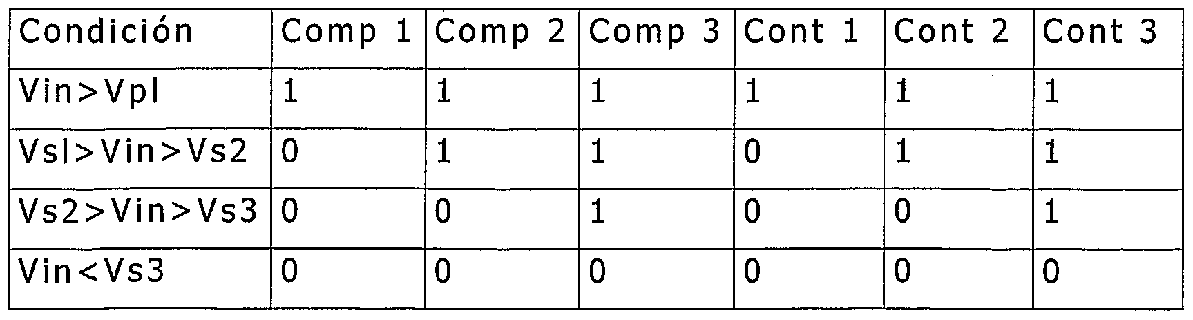
En el caso de uso de un suministro de balasto como una entrada de voltaje, cuando el nivel de voltaje es más alto que el voltaje 1 seleccionado, las salidas de los comparadores será n como se muestra en Ia Tabla 1. En Ia línea correspondiente y en esta condición también se m uestra el contactor q ue debe activar esta Ta bla lógica de entrada y sa lida .In the case of using a ballast supply as a voltage input, when the voltage level is higher than the selected voltage 1, the comparator outputs will be n as shown in Table 1. In the corresponding line and In this condition, the contactor that must activate this logic input and output table is also shown.
En Ia Tabla 1 se muestra Ia operación de Ia salida lógica para cada condición de control .Table 1 shows the operation of the logic output for each control condition.
TABLA 1TABLE 1
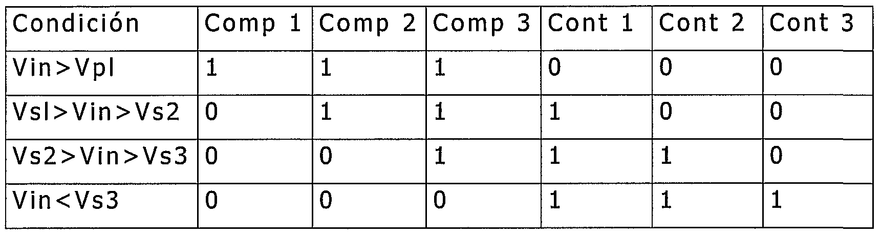
En Ia Tabla 2 se muestra Ia operación de Ia salida lógica para cada condición de control .Table 2 shows the operation of the logic output for each control condition.
TABLA 2TABLE 2
Con referencia a Ia Figura 5, se muestra una modalidad en donde el diagrama del activador del contactor es Ia tecnología contactor CMOS (unidad 6), en donde los comparadores de salida (descritos en Ia Figura 4) alimentan el opto-aislador (unidad 3), a través de Ia unidad 1 de resistencia, Io cual carga Ia unidad 4 del capacitor en una forma lenta en función de Ia unidad 2 de valor de resistencia. Al inicio de Ia conducción, una rampa ascendente de voltaje activa el contactor en una transición lenta . Un proceso similar de transición se lleva a cabo cuando el dispositivo está apagado.With reference to Figure 5, a mode is shown in which the diagram of the contactor activator is the CMOS contactor technology (unit 6), where the output comparators (described in Figure 4) feed the opto-isolator (unit 3 ), through the resistance unit 1, which loads the capacitor unit 4 in a slow manner depending on the resistance value unit 2. At the beginning of the conduction, an ascending voltage ramp activates the contactor in a slow transition. A similar transition process is carried out when the device is turned off.
La Figura 6 muestra una modalidad en donde el diagrama activador del contactor es una unidad 6 del contactor del transistor bipolar.Figure 6 shows a mode where the contactor activator diagram is a unit 6 of the bipolar transistor contactor.
La Figura 7 muestra una modalidad en donde el diagrama activador del contactor es un contactor electro-mecánico. La salida compara Ia señal de Ia Figura 4, Ia cual está conectada con Ia entrada de una unidad 1 amplificadora de refuerzo para activar Ia unidad 2 de contactor electro-mecánico. La Figura 7A muestra una modalidad en donde el diagrama activador del contactor es una unidad 6 de contactor triac, en donde los comparadores de salida (descritos en Ia Figura 4) alimentan el opto-aislador (unidad 3), a través de Ia unidad 1 de resistencia, Io cual carga Ia unidad 2 del capacitor a través de Ia unidad 4 de resistencia . En el estado de conducción, un voltaje en Ia unidad 2 del capacitor, produce una corriente a través de Ia unidad 5 de resistencia, y activa Ia unidad 6 de contactor triac.Figure 7 shows a mode where the diagram Contactor activator is an electro-mechanical contactor. The output compares the signal of Figure 4, which is connected to the input of a booster amplifier unit 1 to activate the electro-mechanical contactor unit 2. Figure 7A shows an embodiment where the contactor activator diagram is a triac contactor unit 6, where the output comparators (described in Figure 4) feed the opto-isolator (unit 3), through the unit 1 of resistance, which loads the unit 2 of the capacitor through the unit 4 of resistance. In the conduction state, a voltage in the capacitor unit 2, produces a current through the resistance unit 5, and activates the triac contactor unit 6.
Aunque Ia invención ha sido descrita con referencia a las modalidades específicas, esta descripción no tiene Ia intención de considerarse limitante en ningún sentido. Varias modificaciones de las modalidades descritas, así como las modalidades alternativas de Ia invención serán evidentes para las personas experimentadas en Ia técnica luego de hacer referencia a Ia descripción de esta invención . Por Io tanto, se contempla que las reivindicaciones anexan cubran las modificaciones que caigan dentro del alcance de Ia invención.Although the invention has been described with reference to specific modalities, this description is not intended to be considered limiting in any way. Various modifications of the described modalities, as well as the alternative modalities of the invention will be evident to the persons skilled in the art after referring to the description of this invention. Therefore, it is contemplated that the appended claims cover the modifications that fall within the scope of the invention.
Se hace constar que con relación a esta fecha, el mejor método conocido por Ia solicitante para llevar a Ia práctica Ia citada invención, es el que resulta claro de Ia presente descripción de Ia invención. It is noted that in relation to this date, the best method known by the applicant to implement the said invention is that which is clear from the present description of the invention.
Claims
Priority Applications (2)
| Application Number | Priority Date | Filing Date | Title |
|---|---|---|---|
| MX2007003073A MX2007003073A (en) | 2004-12-06 | 2005-12-02 | Automatic light attenuator for electronic and magnetic ballasts (high-intensity discharge or fluorescent). |
| BRPI0518364-2A BRPI0518364A2 (en) | 2004-12-06 | 2005-12-02 | device to attenuate a lamp so that a quantity of light is in a previously selected location |
Applications Claiming Priority (2)
| Application Number | Priority Date | Filing Date | Title |
|---|---|---|---|
| US63375104P | 2004-12-06 | 2004-12-06 | |
| US60/633,751 | 2004-12-06 |
Publications (1)
| Publication Number | Publication Date |
|---|---|
| WO2006062387A1 true WO2006062387A1 (en) | 2006-06-15 |
Family
ID=36578163
Family Applications (1)
| Application Number | Title | Priority Date | Filing Date |
|---|---|---|---|
| PCT/MX2005/000112 Ceased WO2006062387A1 (en) | 2004-12-06 | 2005-12-02 | Automatic light attenuator for electronic and magnetic ballasts (high-intensity discharge or fluorescent) |
Country Status (4)
| Country | Link |
|---|---|
| US (3) | US7336041B2 (en) |
| BR (1) | BRPI0518364A2 (en) |
| MX (1) | MX2007003073A (en) |
| WO (1) | WO2006062387A1 (en) |
Families Citing this family (24)
| Publication number | Priority date | Publication date | Assignee | Title |
|---|---|---|---|---|
| US7336041B2 (en) * | 2004-12-06 | 2008-02-26 | Vicente Aldape Ayala | Automatic light dimmer for electronic and magnetic ballasts (fluorescent or HID) |
| US20080143272A1 (en) * | 2006-12-16 | 2008-06-19 | Hunter Fan Company | Light with dimmer |
| US20090001270A1 (en) * | 2007-06-28 | 2009-01-01 | Aleph America | RF detector and temperature sensor |
| KR20100045671A (en) * | 2008-10-24 | 2010-05-04 | 주식회사 필룩스 | Electric ballast |
| US8358085B2 (en) * | 2009-01-13 | 2013-01-22 | Terralux, Inc. | Method and device for remote sensing and control of LED lights |
| US9326346B2 (en) | 2009-01-13 | 2016-04-26 | Terralux, Inc. | Method and device for remote sensing and control of LED lights |
| WO2011022870A1 (en) * | 2009-08-24 | 2011-03-03 | Wang Lvsha | Ballast control apparatus and ballast apparatus configured for high intensity gas discharge lamp |
| WO2012087268A2 (en) * | 2009-11-17 | 2012-06-28 | Terralux, Inc. | Led power-supply detection and control |
| EP2617266A1 (en) | 2010-09-16 | 2013-07-24 | Terralux, Inc. | Communication with lighting units over a power bus |
| US9596738B2 (en) | 2010-09-16 | 2017-03-14 | Terralux, Inc. | Communication with lighting units over a power bus |
| US8754591B2 (en) | 2011-09-06 | 2014-06-17 | Intelliswitch, Sa De Cv | Light dimmer for fluorescent lamps and methods for use thereof |
| CN102395240B (en) * | 2011-11-15 | 2013-07-03 | 庄景阳 | External resistor control HID (high intensity discharge) xenon lamp efficiency output apparatus |
| US8896231B2 (en) | 2011-12-16 | 2014-11-25 | Terralux, Inc. | Systems and methods of applying bleed circuits in LED lamps |
| US10340692B2 (en) | 2012-04-19 | 2019-07-02 | Pass & Seymour, Inc. | Universal power control device |
| US8963434B2 (en) | 2012-09-14 | 2015-02-24 | Cooper Technologies Company | Electrical switch device with automatic dimming control |
| US9265119B2 (en) | 2013-06-17 | 2016-02-16 | Terralux, Inc. | Systems and methods for providing thermal fold-back to LED lights |
| CN106339011A (en) * | 2015-07-10 | 2017-01-18 | 深圳市中兴微电子技术有限公司 | Chip temperature detection and control method and device |
| US10536449B2 (en) | 2015-09-15 | 2020-01-14 | Mimecast Services Ltd. | User login credential warning system |
| US11595417B2 (en) | 2015-09-15 | 2023-02-28 | Mimecast Services Ltd. | Systems and methods for mediating access to resources |
| US9927821B2 (en) | 2016-05-25 | 2018-03-27 | Innovative Building Energy Control | Building energy control systems and methods |
| US10806008B2 (en) | 2016-05-25 | 2020-10-13 | Innovative Building Energy Control | Building energy control systems and methods |
| US9746371B1 (en) * | 2017-01-11 | 2017-08-29 | Crestron Electronics, Inc. | Light sensor calibration system and method |
| US11705275B2 (en) | 2019-12-02 | 2023-07-18 | Panoramic Power Ltd. | Self calibration by double signal sampling |
| CN112072648B (en) * | 2020-08-28 | 2022-02-01 | 武汉大学 | Method for judging optimal access point of electric energy quality control device for inhibiting inter-harmonic resonance |
Citations (5)
| Publication number | Priority date | Publication date | Assignee | Title |
|---|---|---|---|---|
| US2648823A (en) * | 1950-01-06 | 1953-08-11 | Bell Telephone Labor Inc | Thermoelectric translation device |
| US5079455A (en) * | 1990-07-11 | 1992-01-07 | Northern Telecom Limited | Surge current-limiting circuit for a large-capacitance load |
| US5357170A (en) * | 1993-02-12 | 1994-10-18 | Lutron Electronics Co., Inc. | Lighting control system with priority override |
| EP0917411A2 (en) * | 1997-11-12 | 1999-05-19 | Hubbell Incorporated | Multi-voltage ballast and dimming circuits for a lamp driven voltage transformation and ballasting system |
| US5910711A (en) * | 1996-12-02 | 1999-06-08 | U.S. Philips Corporation | Discharge lamp dimmer circuit with piezo-electric transformer and adjustable capacitor |
Family Cites Families (20)
| Publication number | Priority date | Publication date | Assignee | Title |
|---|---|---|---|---|
| US3944876A (en) * | 1974-09-30 | 1976-03-16 | Chadwick-Helmuth Company, Inc. | Rapid starting of gas discharge lamps |
| US4147961A (en) * | 1977-12-19 | 1979-04-03 | Westinghouse Electric Corp. | Energy-conserving solid-state-controlled illumination system |
| US4287455A (en) * | 1979-12-18 | 1981-09-01 | Erin Engineering (Ontario) Ltd. | Power saving circuit for gaseous discharge lamps |
| US4379237A (en) * | 1981-09-17 | 1983-04-05 | Mosteller Jr Lawson P | Light intensity control device and circuit therefor |
| US4791338A (en) * | 1986-06-26 | 1988-12-13 | Thomas Industries, Inc. | Fluorescent lamp circuit with regulation responsive to voltage, current, and phase of load |
| US4697122A (en) * | 1986-08-01 | 1987-09-29 | Armstrong World Industries, Inc. | Slow acting photo lamp control |
| US4950963A (en) * | 1988-05-05 | 1990-08-21 | Sievers Richard L | Automatic light dimmer for gas discharge lamps |
| US5043635A (en) * | 1989-12-12 | 1991-08-27 | Talbott Edwin M | Apparatus for controlling power to a load such as a fluorescent light |
| US5729097A (en) * | 1990-11-29 | 1998-03-17 | Holzer; Walter | Method and device for controlling electric discharge lamps with electronic fluorescent lamp ballasts |
| MX9207339A (en) * | 1991-12-17 | 1993-07-01 | Intelliswitch Inc | LIGHTING REGULATOR APPARATUS FOR GAS DISCHARGE LAMPS. |
| DE4406083A1 (en) * | 1994-02-24 | 1995-08-31 | Patent Treuhand Ges Fuer Elektrische Gluehlampen Mbh | Circuit arrangement for operating at least one low-pressure discharge lamp |
| DE19816815C1 (en) * | 1998-04-16 | 1999-11-11 | Vossloh Schwabe Gmbh | Ballast for operating a plurality of discharge lamps |
| US6046550A (en) * | 1998-06-22 | 2000-04-04 | Lutron Electronics Co., Inc. | Multi-zone lighting control system |
| US6188181B1 (en) * | 1998-08-25 | 2001-02-13 | Lutron Electronics Co., Inc. | Lighting control system for different load types |
| US6147466A (en) * | 1998-12-30 | 2000-11-14 | Commercial Vehicle Systems, Inc. | Synchronization system for motors |
| US6172466B1 (en) * | 1999-02-12 | 2001-01-09 | The Hong Kong University Of Science And Technology | Phase-controlled dimmable ballast |
| US6700333B1 (en) * | 1999-10-19 | 2004-03-02 | X-L Synergy, Llc | Two-wire appliance power controller |
| US6870329B2 (en) * | 2002-04-26 | 2005-03-22 | Vector Products, Inc. | PWM controller with automatic low battery power reduction circuit and lighting device incorporating the controller |
| KR100680386B1 (en) * | 2004-01-15 | 2007-02-08 | 마츠시타 덴끼 산교 가부시키가이샤 | Solid state imaging device, manufacturing method of solid state imaging device and camera using same |
| US7336041B2 (en) | 2004-12-06 | 2008-02-26 | Vicente Aldape Ayala | Automatic light dimmer for electronic and magnetic ballasts (fluorescent or HID) |
-
2005
- 2005-10-27 US US11/259,801 patent/US7336041B2/en not_active Expired - Fee Related
- 2005-12-02 WO PCT/MX2005/000112 patent/WO2006062387A1/en not_active Ceased
- 2005-12-02 BR BRPI0518364-2A patent/BRPI0518364A2/en not_active IP Right Cessation
- 2005-12-02 MX MX2007003073A patent/MX2007003073A/en active IP Right Grant
-
2007
- 2007-09-14 US US11/900,949 patent/US7759879B2/en not_active Expired - Fee Related
-
2010
- 2010-07-20 US US12/840,108 patent/US8193732B2/en not_active Expired - Fee Related
Patent Citations (5)
| Publication number | Priority date | Publication date | Assignee | Title |
|---|---|---|---|---|
| US2648823A (en) * | 1950-01-06 | 1953-08-11 | Bell Telephone Labor Inc | Thermoelectric translation device |
| US5079455A (en) * | 1990-07-11 | 1992-01-07 | Northern Telecom Limited | Surge current-limiting circuit for a large-capacitance load |
| US5357170A (en) * | 1993-02-12 | 1994-10-18 | Lutron Electronics Co., Inc. | Lighting control system with priority override |
| US5910711A (en) * | 1996-12-02 | 1999-06-08 | U.S. Philips Corporation | Discharge lamp dimmer circuit with piezo-electric transformer and adjustable capacitor |
| EP0917411A2 (en) * | 1997-11-12 | 1999-05-19 | Hubbell Incorporated | Multi-voltage ballast and dimming circuits for a lamp driven voltage transformation and ballasting system |
Also Published As
| Publication number | Publication date |
|---|---|
| US7336041B2 (en) | 2008-02-26 |
| BRPI0518364A2 (en) | 2008-11-18 |
| MX2007003073A (en) | 2007-05-21 |
| US20110127928A1 (en) | 2011-06-02 |
| US20080054823A1 (en) | 2008-03-06 |
| US8193732B2 (en) | 2012-06-05 |
| US20060119288A1 (en) | 2006-06-08 |
| US7759879B2 (en) | 2010-07-20 |
Similar Documents
| Publication | Publication Date | Title |
|---|---|---|
| WO2006062387A1 (en) | Automatic light attenuator for electronic and magnetic ballasts (high-intensity discharge or fluorescent) | |
| CN103181241B (en) | The method of LED retrofit lamp, illuminator and operation LED retrofit lamp | |
| JP3947720B2 (en) | How to use dimming control lighting device for incandescent lamp | |
| JP5414789B2 (en) | Commercial power supply synchronous control device and control method thereof | |
| JP5214694B2 (en) | LED drive circuit, LED illumination lamp, LED illumination device, and LED illumination system | |
| TWI551185B (en) | Power supply circuit for light emitting diode | |
| US20110031890A1 (en) | Led emulation of incandescent bulb brightness and color response to varying power input and dimmer circuit therefor | |
| CN103327682A (en) | Adaptive filter for LED dimmer | |
| TW201313056A (en) | Responding to the output of a dimmer to control the light output of one or more LEDs | |
| EP3871471B1 (en) | Led lamp arrangement with controlled power | |
| CN1407842A (en) | Dimmers for compact fluorescent lamps | |
| KR20090048100A (en) | LED Dimming Control Power Supply | |
| CN1304632A (en) | Bi-level output electronic high intensity discharge (HID) ballast system | |
| JP2010245014A (en) | Non-flashing brightness adjustment device for non-resistance light emitting load | |
| JP5639177B2 (en) | Electronic ballast dimming circuit | |
| WO2008155714A1 (en) | Lamp driver, lighting system and method | |
| KR100647845B1 (en) | Phase control circuit of dimmer | |
| Rakotomalala et al. | HID lamps dimming in the public lighting installations dominated by magnetic ballasts | |
| JP3315400B2 (en) | Discharge lamp lighting device, bulb shaped discharge lamp, dimmer and lighting kit for dimming | |
| JP6262775B2 (en) | Dimmable LED lamp activated on demand side | |
| US20160381774A1 (en) | Methods and systems for controlling an electrical load | |
| KR200357687Y1 (en) | Phase adjustment circuit of dimming apparatus | |
| JP2006093009A (en) | High pressure discharge lamp lighting device and lighting system | |
| CN107277965A (en) | Light source driver and lighting device including the light source driver | |
| Rakotomalala et al. | High energy saving for africa street lighting using individual automatic dimming of HID ballasts |
Legal Events
| Date | Code | Title | Description |
|---|---|---|---|
| AK | Designated states |
Kind code of ref document: A1 Designated state(s): AE AG AL AM AT AU AZ BA BB BG BR BW BY BZ CA CH CN CO CR CU CZ DE DK DM DZ EC EE EG ES FI GB GD GE GH GM HR HU ID IL IN IS JP KE KG KM KN KP KR KZ LC LK LR LS LT LU LV LY MA MD MG MK MN MW MX MZ NA NG NI NO NZ OM PG PH PL PT RO RU SC SD SE SG SK SL SM SY TJ TM TN TR TT TZ UA UG US UZ VC VN YU ZA ZM ZW |
|
| AL | Designated countries for regional patents |
Kind code of ref document: A1 Designated state(s): BW GH GM KE LS MW MZ NA SD SL SZ TZ UG ZM ZW AM AZ BY KG KZ MD RU TJ TM AT BE BG CH CY CZ DE DK EE ES FI FR GB GR HU IE IS IT LT LU LV MC NL PL PT RO SE SI SK TR BF BJ CF CG CI CM GA GN GQ GW ML MR NE SN TD TG |
|
| 121 | Ep: the epo has been informed by wipo that ep was designated in this application | ||
| WWE | Wipo information: entry into national phase |
Ref document number: MX/a/2007/003073 Country of ref document: MX |
|
| NENP | Non-entry into the national phase |
Ref country code: DE |
|
| 122 | Ep: pct application non-entry in european phase |
Ref document number: 05815940 Country of ref document: EP Kind code of ref document: A1 |
|
| ENP | Entry into the national phase |
Ref document number: PI0518364 Country of ref document: BR |