DESCRIPTION
CORROSION/ABRASION RESISTANT ALLOY FOR COATING METAL SURFACE
Technical Field
The present invention is related to an alloy suitable as a coating metal material having corrosion or abrasion resistance, especially for an alloy suitable for a member of a device or apparatus used in a corrosive environment such as a seawater, chemicals, or the like, and used for preventing the device or apparatus from being damaged due to corrosion, abrasion and erosion.
Background Art
In a fluid machinery such as a pump or waterwheel used in a corrosive environment such as a seawater or chemicals and subjected to slurry erosion due to sands or scales contained in the handled fluid, a main structural member of the machinery in contact with the fluid, such as a casing or impeller, is usually made of a stainless steel. Stainless steels are superior in corrosion resistance as well as cost performances. However, slide members such as liner rings for the impeller or bearings may be damaged by abrasion and sometimes severely damaged by slurry erosion when the handled fluid contains solids such as sands or scales. Also, the slide member comprises a sliding surface or an attachment portion to be attached to the machinery body, and inevitably comprises a narrow gap between a confronting member. Since the fluid inside the gap is difficult to be replaced by the outside fluid, pitting corrosion is likely to occur on the surface, and crevice corrosion may also occur due to the galvanic cell effect created between the inside and outside surfaces of the gap. Generation of the crevice corrosion is a big problem for austenitic stainless steels which exhibit superior corrosion
resistance in a flowing seawater. Since this difficulty in fluid replacement between inside and outside of the gap portion is significant when the pump is out of operation, the slide member of a pump having gone through frequent stops is damaged by pitting corrosion or crevice corrosion and forced to be exchanged after a short life period. One method generally used for providing the member with a local erosion resistance (abrasion/erosion resistance) is to coat the surface with a hard material, which has been proved abundantly successful. Representative materials used for this purpose include a Co-based alloy named stellite, and a Ni-based alloy named colmonoy. However, these materials are not crevice corrosion resistant, and rapidly corrode when they are applied to a member used in an environment containing a seawater or the like and is accompanied with a gap. Materials with a superior crevice corrosion resistance, on the other hand, include Ni-based alloys such as Inconel 625 and Hasteiioy C, which are locally coated on a surface of the member by build-up welding so as to prevent damages due to pitting corrosion or crevice corrosion. However, these materials have less hardness than the above-mentioned hard coating materials and cannot endure abrasion or erosion. One method for obtaining both abrasion/erosion resistance and corrosion resistance is to prepare a sintered body consisting of a carbide powder and a Ni-based alloy powder such as Inconel 625 above-mentioned. The method, however, has not been developed into a practical use because of technical and economical difficulties in manufacturing large and complicate-shaped members, as well as because sintered bodies have a strength problem for use as a structural member. A slide member such as an impeller liner ring or a bearing of a pump is damaged by abrasion or slurry erosion if the fluid to be handled is corrosive as a seawater or chemicals and including solids such as sands or scales. Also, a sliding surface of the sliding member or a portion to be attached to the pump body is accompanied by a structurally inevitable gap portion, in which pitting corrosion
or crevice corrosion proceeds in a long term use period. Therefore, a sliding member suitable for a pump for handling a corrosive fluid containing solids such as sands or scales should necessarily have both abrasion/erosion resistance and corrosion resistance. Since only limited portions are required to have the above- mentioned properties, it is optimal to coat a desired material on the portions of the base material by locally applying a coating material.
Disclosure of Invention In considering the above aspects, the inventors have obtained the following understandings (a) ~ (f) through a research in developing a method to prevent abrasion/erosion and pitting and crevice corrosions at a lower cost, while specifically keeping an eye on a coated material. (a) The corrosion protection metal material to be built-up or overlaid on a gap portion surface is preferably of a low melting point (equal to or lower than the stainless steel) for providing a good working efficiency in the build-up welding process. It is necessary to exclude generation of voids or cavities as well as inclusion of contaminant such as oxides in the coated material. The coated material is preferably able to provide adequate corrosion protection even with a thin layer for economical reasons. Ni-based alloys optimally satisfy all of the above requirements. (b) While Ni alone provides inadequate resistance against pitting corrosion and crevice corrosion in a seawater, addition of appropriate amount of Cr and Mo can provide superior resistance against pitting and crevice corrosions. (c) A hard material is required for avoiding abrasion due to sliding contact or slurry erosion, thus, a cermet, which is a compound of a metal and a carbide, is suitable for surface coating. It is preferable to prepare a cermet by depositing a carbide through a reaction between components of the coated material during the build-up welding process than by welding a ready mixture of a carbide and metal material. (d) Appropriate addition of V, which has a low free energy for
generating carbides, together with C can provide stable carbide deposition described above during overlay welding process and, also, carbide deposition of a part of Cr and Mo, to thereby obtain superior abrasion/erosion resistance. (e) Silicon functions as an oxidizer as well as improves molten metal flowability. (f) Since partial replacement of Ni with Fe in the overlay metal does not deteriorate pitting corrosion or crevice corrosion resistance, appropriate addition of Fe can lower a cost of the overlay metal as well as enhance workability. The present invention is aimed to provide a fluid machinery member having superior abrasion resistance and corrosion resistance. A Ni-Cr-Mo-V-C based alloy of a first invention essentially consists of, by weight: 23-50% Cr; 7-20% V; C not less than 1.6% and not more than
(0.236V%+2)%; Mo not more than 40% and not less than any of (11-0.1 xCr%) and (125-4χCr%)%; and the balance of Ni and inevitable impurities. The total amount of Cr, V, and Mo is not more than 90%. A Ni-Cr-Mo-V-C based alloy of a second invention essentially consists of, by weight: 23-50% Cr; 7-20% V; 0.5-4.5% Si and C not less than 1.6% and not more than (0.236V%+2)%; Mo not more than 40% and not less than any of (11 -0.1 xCr%) and (125-4χCr%)%; and the balance of Ni and inevitable impurities.
The total amount of Cr, V, and Mo is not more than 90%. A Ni-Cr-Mo-V-C based alloy of a third invention essentially consists of, by weight: 2.5-25% Fe; 23-50% Cr; 7-20% V; 0.5-4.5% Si and C not less than
1.6% and not more than (0.236V%+2)%; Mo not more than 40% and not less than any of (11-0.1xCr%) and (125-4χCr%)%; and the balance of Ni and inevitable impurities. The total amount of Fe, Cr, V, and Mo is not more than 90%. A carbide of at least one element selected from Cr, Mo, and V may be deposited through a melting and solidification process. In a method of surface treatment of a member according to another invention, the alloy may be melted and solidified on a surface of the member to deposit therein a carbide of at least one element selected from Cr, Mo, and V.
Brief Description of Drawings
Fig. 1 is a front view of a testing body; Fig. 2 is a vertical cross-sectional view of the testing body; and Fig. 3 is a schematic drawing showing a representative example of repeated anodic polarization curve.
Best Mode for Carrying Out the Invention
The alloy suitable as a coating layer material for use in the apparatus according to the present invention comprises chromium (Cr), molybdenum (Mo), vanadium (V), carbon (C), silicon (Si), and iron (Fe) in amounts as described above, and the reasons for defining the composition will be described herein. (a) Chromium Cr is an element providing the material with a passivation ability to thereby enhance passivity, by adding to Ni, and serving to lower the melting point. Cr is also a carbide formation element to obtain hardening of the coating layer due to carbide deposition. The coating layer of a coated material according to the present invention comprises two phases comprising a matrix metal phase and a carbide deposition phase, and the metal phase determines corrosion resistance property. Cr is contained in both two phases described above, and since it is difficult to control the amount of Cr carbide generated during the coating process, it is necessary to determine Cr addition necessary to enhance passivation and lower the melting point, by considering the amount consumed for deposition of carbides. Accordingly, Cr composition is determined by solely considering main effects of passivity enhancement and melting point lowering, without considering a secondary effect of hardness enhancement due to carbide deposition. Since less than 23% Cr addition does not provide a desired effect and excessive addition of more than 50% does not provide a prominent progress in passivity
enhancement, Cr content was defined to 23-50%. (b) Molybdenum Mo is highly effective for preventing crevice corrosion in a seawater. Also, Mo is, likely to Cr, a carbide formation element to provide hardening of the coating layer due to carbide deposition. Accordingly, Mo composition is similarly decided, i.e., by considering the main effects of passivity enhancement and melting point lowering without considering secondary effect of hardness enhancement due to carbide deposition. The lower limit was determined in relationship with Cr composition. Since either less than 11-0.1 xCr% addition or less than 125-4χCr% addition does not provide a desired crevice corrosion protection effect. On the other hand, more than 40% addition does not provide a prominent progress in crevice corrosion improvement. Thus, Mo content was defined as neither less than (11-0.1 xCr%), nor less than (125-4xCr%)%, and not more than 40%. (c) Vanadium V is an element having a carbide formation free energy lower than Cr or Mo, thus it can provide hardening effect due to carbide deposition most efficiently. While less than 7% addition does not provide a desired hardening effect, more than 20% addition exhibited deterioration of corrosion resistance, which resulted in addition limitation of 7-20%. (d) Carbon C is an element for depositing carbides by coupling with V, Cr, or Mo to harden the coating layer, and is mainly consumed for vanadium carbide deposition. Less than 1.6% addition does not provide a desired hardening effect of the coating layer. On the other hand, stoichiometric amount of C for forming vanadium carbide for all of V contained in the coating layer is V%x12.011 (atomic weight ofr C)/50.942(atomic weight of V) = 0.236χV%. However, C is also consumed to form carbides with Cr and Mo other than V, so that C content of 0.236χV% is not sufficient for forming vanadium carbide for all of V contained in the coating layer. Thus, C content is defined as not less than 1.6% and not more

(e) Silicon Si is an element having a strong affinity with oxygen, so that it can effectively function to eliminate oxides by coupling with oxygen within the coating layer, as well as facilitate smooth molten metal flow. However, less than 0.5% addition does not provide a desired effect described above, whereas more than 4.5% addition does not provide a prominent progress of the above described effect. Thus, Si content is defined as 0.5-4.5%. (f) Iron Since Fe is an element capable of reducing the cost of the coating layer as well as improving workability thereof, addition is determined according to necessity for the above-mentioned properties. Also, since pure V is of a high melting point and expensive, V is preferably added as ferrovanadium (FeV) which is another reason for inclusion of Fe. Since less than 2.5% addition does not provide a desired effect described above, whereas more than 25% addition deteriorates corrosion resistance, Fe content is defined as 2.5-25%. In the process of applying these coating metal material, fine voids, potentially causing crevice corrosion, should be eliminated from the boundary between the base metal and the coating layer or from the coating layer itself, such coating method is established by: build-up welding of the powdered material by a plasma transferred arc welding process; thermal spray coating of the powdered material; build-up welding by a TIG welding process or a submerged arc welding process, using a welding rod of the material; or a self-fluxing alloy coating method including spraying the powdered material or applying a mixture of the powdered alloy with an organic bond and then melting the material by heating. A member coated with the overlay metal according to the present invention is remarkably effective when used as a slide member for a pump or waterwheel handling a corrosive, single- or plural- phase fluid such as a seawater or chemicals, which does not, however, mean to limit the application of the invention. Erosion is generally classified into: rain erosion for a single phase liquid flow; sand erosion for a double phase flow including gas and solid; slurry
erosion for a double phase flow including solid and liquid; and cavitation erosion for a double phase flow including gas and liquid. The alloy of the present invention provides superior erosion resistance for all of the cases described above. For example, if the alloy is coated on the area of the impeller, where cavitation occurs, of a pump handling a corrosive fluid, it can prevent generation of cavitation erosion by taking advantage of having superior corrosion and abrasion/erosion resistance. Further, the member coated with the alloy of the present invention is used as a member which is required to concurrently have corrosion resistance and abrasion/erosion resistance and for devices or apparatuses other than pumps. For example, it is advantageously applied to a member exposed to a high temperature gaseous environment including chloride or sulfur and located at a position subjected to erosion caused by collision with scattered slugs or calcination residues. It is also advantageously applied to a member used in a pump or a pipe for transferring cooling water in a thermal or nuclear power plant, in which corrosion resistance is particularly required. It is also advantageously applied to a member for an inner element of a fluidized bed reactor provided in a chemical plant or the like and using a highly corrosive reagent and a solid catalyst, or a member for a blade of an agitator or bearing for a chemical reactor, which is required to have corrosion resistance as well as abrasion resistance.
TABLE 1
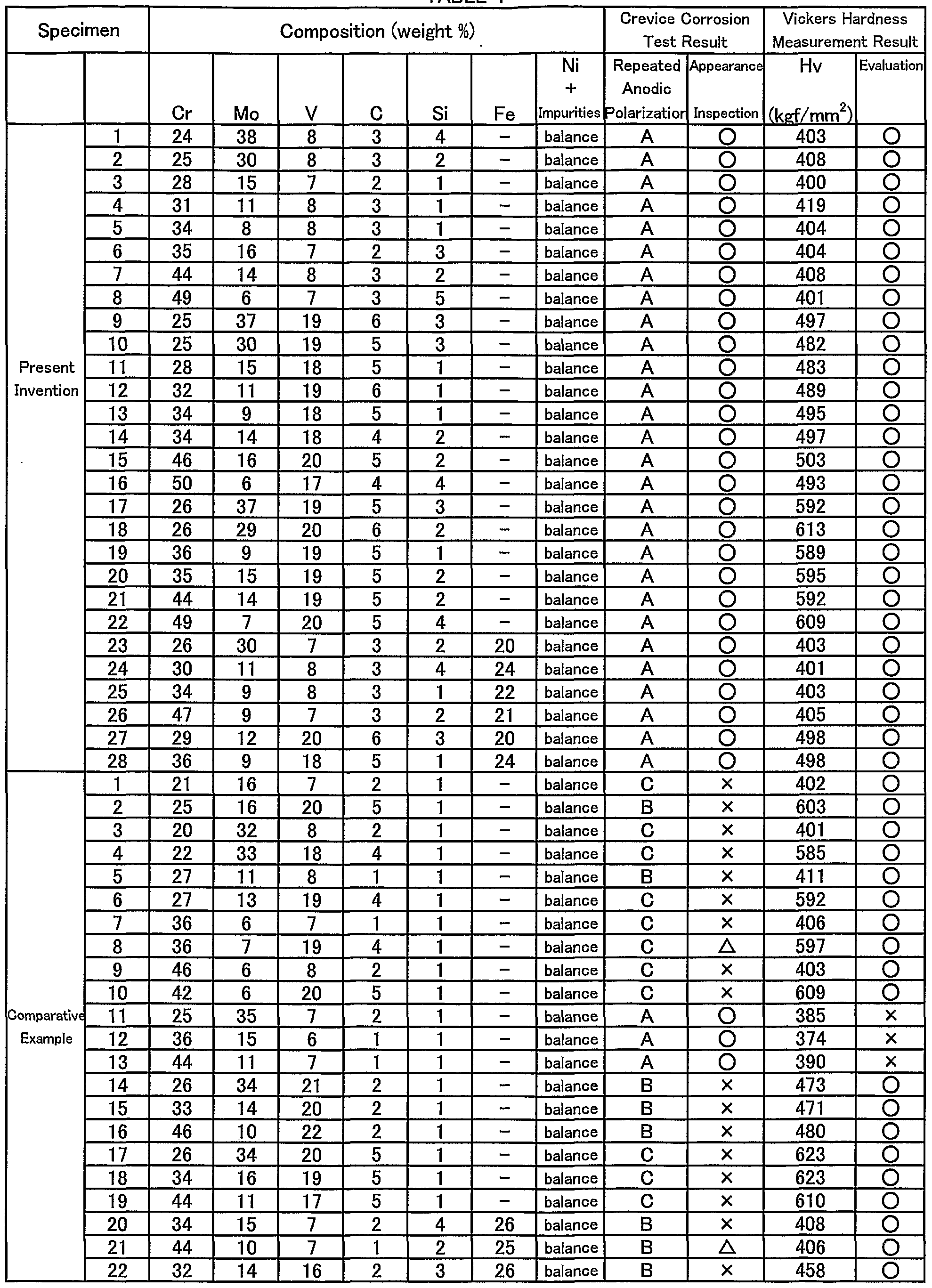
(Embodiment 1) The present invention will be described by way of preferred embodiments in comparison with comparative examples. Table 1 shows compositions, and test results of a crevice corrosion test and a hardness test for the coating metal material of the present invention and comparative examples. To start with, powders of each composition shown in Fig. 1 is prepared by an atomizing process, which are then classified and adjusted into a particle size of 10~50μm range. Each of the powders is processed in the following steps to provide a specimen with a build-up coating. Two 3mm thick build-up layers were formed on one surface of a SUS304 plate of 60mm wide, 100mm long, and 10mm thick by a plasma transferred arc welding process. Then, a 1 mm thick surface portion is removed by machining the specimen to expose the second coating metal layer. An EPMA analysis was conducted in advance for the surface and section of the coating layer to confirm that base plate element is not mixed into the second layer by dilution, so that the exposed surface of the coating layer belongs to an alloy having identical composition with the coating metal material. A 30mm square test piece was cut out from the specimen for a crevice corrosion test. As shown in a front view of Fig. 1 and a vertical cross-sectional view of Fig. 2, a 10mm square polytetrafluoroethylene plate 4 is fastened to the central portion of the coating layer side surface of the square test piece 3 by using a bolt 6 and a nut 7 and via an acrylic plate 5. The front and circumferential surfaces of the test piece 3 were then covered with a silicone resin 2 to make a testing specimen. The test was performed to probe crevice corrosion caused by a solution infiltrated into a fine gap between the test piece 3 and the polytetrafluoroethylene plate 4, so that the testing specimen was immersed in a 3% NaCI solution and a repeated anodic polarization was measured. Fig. 3 shows a schematic view of a representative example of obtained repeated anodic polarization curve. Curves A, B, and C respectively depict the states when potential is varied from a spontaneous potential toward a noble direction at a predetermined rate until
current reaches 6mA (forward route), and is reversed toward an ignoble direction (backward route). In Fig. 3, curve A depicts a case where the forward and backward routes show no substantial difference to result in a superior crevice corrosion resistance. Curve C depicts a case where polarization behaviors are totally different between the forward and backward routes. Here, corrosion current does not decline at all even after turning back the potential to ignoble from noble, so that corrosion, once it occurs, does not stops itself, thus creating a state where crevice corrosion is easily generated. Curve B depicts an intermediate state between the above-mentioned cases A and B. For each of the above-mentioned various testing specimens, the repeated anodic polarization curve was examined and categorized into the above-mentioned three types of curves A, B, C of Fig. 3. The results are shown by notations A, B, and C in Table 1. Also, the appearance of the gap forming portion of each specimen was examined to check generation of any crevice corrosion, and the results were also shown in Table 1 by symbol O if no crevice corrosion was found, x if distinct crevice corrosion was found, and Δ if crevice corrosion was found in some of plural observations. Thus, Table 1 shows that specimens with symbol O have a superior crevice corrosion resistance, specimens with symbol x have a poor crevice corrosion resistance, and specimens with symbol Δ occasionally have a poor crevice corrosion resistance. Appropriate test pieces were cut out for hardness test from the testing specimens after cutting out the corrosion test pieces. The hardness test was conducted by first inspecting the section of the coating layer and then measuring hardness at the midpoint of the thickness of the second layer by a Micro-Vickers hardness tester. The measuring weight was set at 500g. Results for Vickers hardness (Hv) measure on the above-mentioned various testing specimens are shown in Table 1. We adopted Hv 400kgf/mm
2 as a standard value of hardness necessary to exhibit abrasion resistance or erosion resistance, and marked O in the Table 1 when testing specimen was harder than the standard. This means
that the testing specimen marked O is superior with abrasion resistance or erosion resistance. Table 1 clearly shows that, while the build-up coating specimens 1-28 coated with the material of the present invention exhibit a superior crevice corrosion resistance as well as abrasion and erosion resistance, specimens 1 -22 with a coating layer material having composition out of the range of the present invention exhibit inferior properties in crevice corrosion resistance, or any of abrasion resistance and erosion resistance. The appearance of the testing specimens of the present invention was checked before the surface layer is removed, and all of the specimens had a smooth build-up surface showing superior build-up characteristics. (Embodiment 2) A cylindrical member made of SUS304, an austenitic stainless steel, with an outer diameter of 62mmφ, an inner diameter of 51 mmφ, and length of 65mm was prepared. The outer surface of the member was coated with a 1.5mm thick coating layer by plasma transferred arc welding of a Ni-Cr-Mo-V-C based alloy powder comprising 29% Cr (by weight as same hereafter), 11% Mo, 1% Si, 16% V, 5% C, and balance Ni and inevitable impurities, which is then machined to remove the surface layer to make a cylindrical member of an outer diameter of 64.4mmφ, an inner diameter of 53mmφ, and length of 63mm. Although this embodiment employs a base metal of SUS304 which is an austenitic stainless steel, the base metal is not limited in this invention, so that other materials are available as long as they are compatible with a seawater. Also, while the above embodiment employs a plasma transferred arc welding method for coating the metal material, this is not meant to limit the coating method, so that other methods are available as long as they do not generate voids or cavities at the boundaries of the coating layer and base metal or inside the coating layer, which may cause crevice corrosion. A self-fluxing alloy coating method is also available by thermally spraying the powdered material, or applying a mixture of the powdered alloy with an organic bond on the member surface, and then melting the material by heating. Among these methods, plasma transferred arc
welding or TIG welding is desirable in view of long term period liability of the coating layer. The alloy suitable for the coating metal material above-described can be thermally sprayed on the surface of a base material by any thermal spray method to form a corrosion and abrasion resistant layer on the base material. The coating layer can be applied to a base material used as a member required to have corrosion resistance, abrasion resistance, and sand erosion resistance or slurry erosion resistance such as, for example, an impeller, casing, blade, bearing or seal member used in a rotary machine such as a pump, waterwheel or compressor. Formation of the abrasion resistant layer on the base material can provide an improved abrasion resistance thereto, so that machines employing the material such as a pump, waterwheel, and compressor can have a longer life. As described above, the present invention can provide industrially applicable advantages as follow: It can securely prevent abrasion due to sliding contact, erosion due to inclusion of sands or scales, as well as pitting corrosion or crevice corrosion only by providing a thin coating metal layer on any surface of a slide member. The process is very economical since a partial coating is sufficient. It can provide a long term use of a device or apparatus used in a corrosive environment such as a seawater or chemicals by preventing the members from being damaged. It can also extend a life of a mechanical element such as an impeller, bearing, casing, etc. coated by the alloy according to the present invention and a fluid machinery employing the element.