WO2004106083A1 - Heat transfer sheet, image forming material and image forming method - Google Patents
Heat transfer sheet, image forming material and image forming method Download PDFInfo
- Publication number
- WO2004106083A1 WO2004106083A1 PCT/JP2004/007767 JP2004007767W WO2004106083A1 WO 2004106083 A1 WO2004106083 A1 WO 2004106083A1 JP 2004007767 W JP2004007767 W JP 2004007767W WO 2004106083 A1 WO2004106083 A1 WO 2004106083A1
- Authority
- WO
- WIPO (PCT)
- Prior art keywords
- layer
- image forming
- image
- heat transfer
- parts
- Prior art date
- Legal status (The legal status is an assumption and is not a legal conclusion. Google has not performed a legal analysis and makes no representation as to the accuracy of the status listed.)
- Ceased
Links
Classifications
-
- B—PERFORMING OPERATIONS; TRANSPORTING
- B41—PRINTING; LINING MACHINES; TYPEWRITERS; STAMPS
- B41M—PRINTING, DUPLICATING, MARKING, OR COPYING PROCESSES; COLOUR PRINTING
- B41M5/00—Duplicating or marking methods; Sheet materials for use therein
- B41M5/26—Thermography ; Marking by high energetic means, e.g. laser otherwise than by burning, and characterised by the material used
- B41M5/382—Contact thermal transfer or sublimation processes
- B41M5/392—Additives, other than colour forming substances, dyes or pigments, e.g. sensitisers, transfer promoting agents
- B41M5/395—Macromolecular additives, e.g. binders
-
- B—PERFORMING OPERATIONS; TRANSPORTING
- B41—PRINTING; LINING MACHINES; TYPEWRITERS; STAMPS
- B41M—PRINTING, DUPLICATING, MARKING, OR COPYING PROCESSES; COLOUR PRINTING
- B41M5/00—Duplicating or marking methods; Sheet materials for use therein
- B41M5/26—Thermography ; Marking by high energetic means, e.g. laser otherwise than by burning, and characterised by the material used
- B41M5/382—Contact thermal transfer or sublimation processes
- B41M5/385—Contact thermal transfer or sublimation processes characterised by the transferable dyes or pigments
-
- B—PERFORMING OPERATIONS; TRANSPORTING
- B41—PRINTING; LINING MACHINES; TYPEWRITERS; STAMPS
- B41M—PRINTING, DUPLICATING, MARKING, OR COPYING PROCESSES; COLOUR PRINTING
- B41M5/00—Duplicating or marking methods; Sheet materials for use therein
- B41M5/26—Thermography ; Marking by high energetic means, e.g. laser otherwise than by burning, and characterised by the material used
- B41M5/40—Thermography ; Marking by high energetic means, e.g. laser otherwise than by burning, and characterised by the material used characterised by the base backcoat, intermediate, or covering layers, e.g. for thermal transfer dye-donor or dye-receiver sheets; Heat, radiation filtering or absorbing means or layers; combined with other image registration layers or compositions; Special originals for reproduction by thermography
- B41M5/46—Thermography ; Marking by high energetic means, e.g. laser otherwise than by burning, and characterised by the material used characterised by the base backcoat, intermediate, or covering layers, e.g. for thermal transfer dye-donor or dye-receiver sheets; Heat, radiation filtering or absorbing means or layers; combined with other image registration layers or compositions; Special originals for reproduction by thermography characterised by the light-to-heat converting means; characterised by the heat or radiation filtering or absorbing means or layers
- B41M5/465—Infrared radiation-absorbing materials, e.g. dyes, metals, silicates, C black
Definitions
- the present invention relates to a heat transfer sheet, an image formingmaterial and an image formingmethod for forming a high resolution image by use of a laser beam.
- the invention relates to a heat transfer sheet, an image forming material and an image forming method useful for the preparation of a color proof (DDCP: direct digital color proof) or a mask image in the printing field from a digital signal by laser recording.
- DDCP direct digital color proof
- a color proof is prepared from the color separation films for checking errors in a color separation process and necessity of color correction before final printing (actual printing operation) .
- the color proof has been desired to realize high resolving power which enables high reproducibility of a medium image, and to have performances such as high process stability.
- materials used for the actual printed matter such as stock paper (an actual printing paper) as a substrate and a pigment as a colorant are preferably used as materials used for the color proof.
- a dry method using no developing solution is highly desired.
- a DDCP (Direct Digital Color Proof) recording system for directly preparing the color proof from a digital signal has been developed with the recent dissemination of the electronic system in the preliminary process of printing (prepress field) .
- DTP Desk Top Publication
- CTP Computer To Plate
- Such a system is intended for the preparation of color proof of particularly high image quality, and in general, a laser beam which can be modulated by a digital signal and make recording light thin is used as a recording head in the system, whereby a halftone dot image of 150 lines/inch is reproduced. Accordingly, it is necessary to develop an image forming material having high transfer sensitivity to the laser beam and exhibiting high resolution which makes it possible to reproduce highly fine halftone dots.
- a heat melt transfer sheet comprising a support having provided thereon a light-to-heat converting layer absorbing a laser beam to generate heat and an image forming layer in which a pigment is dispersed in a component such as heat-meltable wax or binder, in this order (see Patent Document 1) .
- heat generated in a laser beam-irradiated region of the light-to-heat converting layer melts the image forming layer corresponding to the region to transfer an image onto an image receiving sheet arranged by lamination on the transfer sheet, thereby forming a transferred image on the image receiving sheet.
- Patent Document 2 discloses a heat transfer sheet comprising a support having provided thereon a light-to-heat converting layer containing a light-to-heat converting substance, a heat release layer having an extremely thin thickness (0.03 ⁇ m to 0.3 ⁇ m) and an image forming layer containing a colorant, in -this order.
- irradiation of a laser beam reduces the bonding force between the image forming layer and the light-to-heat converting layer bonded by intervention of the heat release layer to form a highly fine image on an image receiving sheet arranged by lamination on the transfer sheet.
- so-called "ablation" is utilized.
- the heat release layer is partly decomposed to vaporize in a region irradiated with the laser beam, which causes the bonding force between the image forming layer and the light-to-heat converting layer in that region to be weakened to transfer the image forming layer of that region onto the image receiving sheet laminated thereon.
- image formingmethods have the advantages that stock paper provided with an image receiving layer (adhesive layer) as an image receiving sheet material can be used, and that a multicolor image can be easily obtained by transferring images different in color one after another onto an image receiving sheet.
- image formation method utilizing ablation has the advantage that a highly fine image can be easily obtained, and is useful for preparing a color proof (DDCP: Direct Digital Color Proof) or a highly fine mask -image.
- CTP Computer To Plate
- the systems include (1) a laser sublimation system, (2) a laser ablation system and (3) a laser melt system.
- the laser sublimation system of (1) has the problems that the approximation to printed matter is insufficient, because a dye is used as a colorant, and that the contour of a halftone dot is blurred, resulting in insufficient resolution, because the colorant is sublimated.
- the laser ablation system of (2) is good in the approximation to printed matter, because a pigment is used as a colorant, but has the problem that the contour of a halftone dot is blurred, resulting in insufficient resolution, similarly to the sublimation system, because the colorant is scattered. Further, the laser melt system of (3) also has the problem that no clear contour is obtained, because a melt flows.
- Patent Document 3 a laser thin layer transfer system has recently proposed (see, for example, Patent Document 3) as means for making the contour of a halftone dot clear and achieving high resolution and high image quality of transferred image .
- an image forming material containing white pigment for example, titanium oxide is exemplified (see, for example, Patent Document 4) .
- the stain is noticeable.
- Patent Document 1 JP-A-5-58045 (the term "JP-A" as used herein means an "unexamined published Japanese patent application")
- Patent Document 2 JP-A-6-219052
- Patent Document 3 JP-A-2002-274051
- Patent Document 4 JP-A-2001-353968 It is required for the transferred image formed by the above-described laser transfer system to have durability, particularly, strength against scratch. When the strength against scratch of the transferred image is low, lack of image is apt to occur and as a result, a problem arises in that defect of the transferred image occurs in case of transferring multicolor image or in that opacifying power is reduced in case of transferring an image intended to white background.
- an object of the invention is to provide a heat transfer sheet, an image forming material and an image formingmethod exhibiting goodtransfer sensitivity and capable of forming an image having high resolution, white color excellent in the opacifying power and excellent durability.
- Another object of the invention is to provide an image formingmaterial and an image forming method capable of forming an image having good hue, high image quality, a stable transfer density and durability.
- a still another object of the invention is to provide a multicolor image forming material which is prevented from change in hue of an image forming layer due to the decomposed material of infrared absorbing dye formed at the time of laser beam irradiation.
- a still another object of the invention is to provide a multicolor image forming material which can provide a large-size DDCP having an extended range of reproducible hue andparticularly, white color excellent in the opacifyingpower, and a multicolor image forming method using the same.
- a still another object of the invention is to provide a multicolor image forming material which can provide a large-sized DDCP of high grade and high stability and excellent in coincidence in printing.
- a still another object of the invention is to provide a multicolor image forming material which can form an image of good image quality and stable transfer density on an image receiving sheet even when the laser recording is conducted at high energy by multiple laser beams under different conditions of temperature and humidity.
- a further object of the invention is to provide a heat transfer sheet for white image formation which has favorable white hue and opacifying power, provides white image of high image quality and exhibits high transfer sensitivity and high productivity. Disclosure of the Invention
- a heat transfer sheet comprising a support, a light-to-heat converting layer and an image forming layer, wherein the image forming layer contains at least a white pigment and an amorphous organic polymer having a softening point of 40°C to 150°C, an average particle size of the white pigment is from 0.01 ⁇ m to 0.32 ⁇ m, an amount of the white pigment is from 40% by weight to 90% by weight based on the total weight of the image forming layer, an amount of the amorphous organic polymer is from 10% by weight to 60% by weight based on the total weight of the image forming layer , and a thickness of the image forming layer is from 0.5 ⁇ m to 3.0 ⁇ m.
- the white pigment is at least one white pigment selected from titanium oxide, aluminum oxide and silicon oxide.
- the light-to-heat converting layer contains at least a polyamideimide resin or a polyimide resin as a binder.
- the light-to-heat converting layer contains a cyanine dye as a light-to-heat converting agent.
- the image forming layer contains at least one of a blue pigment and a fluorescent brightening agent.
- blue pigment is at least one blue pigment selected from ultramarine blue and organic blue pigments.
- L* is not less than 70, a* is from -3.0 to 0 and b* is from -6.0 to -3.0.
- an opacifying ratio of the image forming layer is not less than 55%.
- thickness of the image forming layer is from 0.5 ⁇ m to 1.8 ⁇ m.
- absorbance (A) of the light-to-heat converting layer at an absorption wavelength of a laser beam used for image recording is from 1.0 to 2.0 and a ratio (A/X) of the absorbance
- An image forming material which comprises an image receiving sheet having an image receiving layer and the heat transfer sheet as described in any one of 1 to 15, and is used by superposing the image forming layer on the image receiving layer of image receiving sheet so that the image forming layer faces the image receiving layer, irradiating the image forming layer with a laser beam, and transferring the irradiated area of the image forming layer onto the image receiving layer of image receiving sheet to perform image recording.
- An image forming method comprising preparing the image forming material as described in 16, superposing the image forming layer on the image receiving layer of image receiving sheet so that the image forming layer faces the image receiving layer, irradiating the image forming layer with a laser beam, and transferring the irradiated area of the image forming layer in the state of a thin film onto the image receiving layer of image receiving sheet.
- Fig. 1 shows views for illustrating an outline of a mechanism of multicolor image formation by thin film heat transfer using a laser beam.
- Fig. 2 is a schematic view showing a structural example of a recording device for laser heat transfer.
- Fig. 3 is a schematic view showing a structural example of a heat transfer device.
- Fig. 4 is a diagram showing a structural example of a system using a recording device for laser heat transfer, FINALPROOF.
- Light-to-heat converting layer 16 Image forming layer 16' : Laser beam-irradiated region 20: Image forming sheet 22: Support for image forming sheet 24: Image receiving layer
- a laser heat transfer recording system for DDCP comprising an image forming material of stock paper transfer, actual halftone dot output and pigment type having a B2 or more size, an output device and a high grade CMS soft.
- the performances are characterized by (1) that the dot form is sharp, so that a halftone dot excellent in the approximation to printed matter can be reproduced, (2) that the hues are good in the approximation to printed matter, and (3) that the record quality is difficult to be influenced by environmental temperature and humidity, and the cyclic reproducibility is good, so that a stable proof can be prepared.
- the technical points of materials giving such characteristics of performances are the establishment of a thin film transfer process and improvements in vacuum adhesion retaining properties, following up to high resolution recording and heat resistance of the materials required for the laser heat transfer system.
- Specific examples thereof include (1) thinning of a light-to-heat converting layer by introduction of an infrared absorption dye, (2) enhancement of the heat resistance of the light-to-heat converting layer by introduction of a high Tg polymer, (3) intending to stabilize hues by introduction of a heat-resistant pigment, (4) control of adhesion and cohesion by addition of a low molecular weight component such as wax or an inorganic pigment and (5) imparting of vacuum adhesion without deterioration of image quality by addition of a matting agent to the light-to-heat converting layer.
- the technical points of the system include (1) air conveyance for continuous accumulation of a large number of sheets in a recoding device, (2) insertion on stock paper for reducing curls after transfer in a heat transfer device and (3) connection of a general-purpose output driver allowed to have system connection expansion.
- the laser heat transfer recording system developed by the inventors is constituted by a variety of characteristics of performances, system constitution and technical points. However, these are for the purpose of illustration and not of limitation.
- the inventors have developed the system based on the idea that individual materials, respective coating layers, for example, a light-to-heat converting layer, an image forming layer and an image receiving layer, each heat transfer sheet and an image receiving sheet should be arranged organically and 'overall, not existing individually and loosely, and the image forming material exhibit the maximum performances in combination with a recording device and a heat transfer device .
- the inventors have examined closely the respective coating layers of the image forming material and the constituent materials, prepared the coating layers bringing out the maximum of features of these materials to form the image formingmaterial, and found suitable ranges of various physical characteristics such that the image forming material exhibits the maximum performances.
- the present invention is positioned as an important invention ' to provide an image forming material suitable for the system, inparticular, to provide a heat transfer sheet, an image forming material and an image forming method capable of forming an image having white color excellent in the opacifying power and durability.
- the heat transfer sheet of the invention is suitably used in combination with an image receiving sheet having an image receiving layer to form an image forming material and suitably used in a image forming method wherein an image forming layer is transferred in the state of a thin film onto an image receiving layer. It is also suitably used for a multicolor image forming material and image forming method in combination with other color heat transfer sheets.
- the heat transfer sheet, image forming material and image forming method according to the invention are suitably used in the above-described system.
- heat transfer sheet W (white)
- the image forming layer contains a white pigment and an amorphous organic polymer
- the white pigment incorporated into the image forming layer of the heat transfer sheet W has ordinarily an average particle size of from 0.01 ⁇ m to 0.32 ⁇ m, preferably from 0.15 ⁇ m to 0.32 ⁇ m, and particularly preferably from 0.27 ⁇ m to 0.31 ⁇ m.
- whiteness of the transfer image obtained becomes poor (insufficient whiteness) .
- it is necessary to increase thickness of the image forming layer which is disadvantageous inviewof transfer sensitivity.
- coarse particles may also disturb adhesion between the image forming layer and the image receiving layer at the transfer and it also causes degradation of the transfer sensitivity.
- problems may occur in the dispersion of pigment, for example, increase in dispersion cost or occurrence of gelation of the dispersion solution.
- An amount of the white pigment is ordinarily from 40% by weight to 90% by weight, preferably from 50% by weight to 80% by weight, based on the total weight of the image forming layer.
- amount of the white pigment is less than 40% by weight, whiteness of the transfer image obtained becomes poor.
- amount of the white pigment exceeds 90% by weight, the image forming layer per se becomes poor in view of heat melting property and difficult to transfer onto stock paper.
- the white pigment examples include titanium oxide, aluminumoxide, silicon oxide, bariumoxide, zinc oxide, calcium oxide and calcium sulfate. Two or more white pigments may be used as a mixture thereof. Particularly, titanium oxide, aluminum oxide and silicon oxide are preferred. Of the titanium oxides, a rutile type titanium oxide is preferably used.
- An amount of the amorphous organic polymer incorporated into the image forming layer of the heat transfer sheet W is ordinarily from 10% by weight to 60% by weight, preferably from 20% by weight to 40% by weight, based on the total weight of the image forming layer.
- amount of the amorphous organic polymer is less than 10% by weight, transferability onto stock paper become poor .
- the amount of the amorphous organic polymer exceeds 60% by weight, cutting of a film of the image forming layer becomes difficult and it is disadvantageous in view of resolution.
- a softening point of the amorphous organic polymer is ordinarily from 40°C to 150°C, preferably from 40°C to 80°C.
- thepolymer include butyral resins, polyamide resins, polyethyleneimine resins, sulfonamide resins, polyesterpolyol resins, petroleum resins, homopolymers or copolymers of styrene and derivatives thereof, for example, styrene, vinyltoluene, ⁇ -methylstyrene, 2-methylstyrene, chlorostyrene, vinyl- benzoic acid, sodium vinylbenzenesulfonate or aminostyrene, andhomopolymers of vinyl monomers, for example, methacrylates, e.g., methyl methacrylate, ethyl methacrylate, butyl methacrylate or hydroxyethyl methacrylate, methacrylic acid, acrylates, for example, methyl acrylate, eth
- components other than the white pigment and amorphous organic polymer may be incorporated, if desired. Other components to be incorporated are described hereinafter.
- a thickness of the image forming layer is ordinarily from 0.5 ⁇ m to 3.0 ⁇ m, preferably from 0.5 ⁇ m to 1.8 ⁇ m.
- the thickness of the image forming layer is less than 0.5 ⁇ m, transfer unevenness may occur.
- the thickness of the image forming layer exceeds 3.0 ⁇ m, transfer sensitivity tends to decrease, resulting in degradation of resolution.
- an intermediate layer is provided between the light-to-heat converting layer and the image forming layer .
- the intermediate layer is a layer having a function for trapping, that is, capturing a light-to-heat converting substance, for example, a dye or a decomposed compound thereof in the light-to-heat converting layer at the time of image recording to prevent or controlmigrationof such compounds into the image forming layer. Therefore, the trap layer is preferably a layer compatible with a decomposed compound of an infrared absorbing dye and the light-to-heat converting layer.
- a binder for the trap layer is preferably an ionomer resin or a water-soluble resin. Also, a resin having a solubility parameter (SP value) of not less than 23 is preferred.
- the intermediate layer acting as the trap layer can be provided not only in the heat transfer sheet W but also in heat transfer sheets for other colors.
- the ionomer resin is a polymer containing ethylene as the main component and includes mordanting resins having a carboxylate, sulfonate, phosphate, quaternary ammonium salt or the like in the side chain thereof.
- mordanting resins having a carboxylate, sulfonate, phosphate, quaternary ammonium salt or the like in the side chain thereof.
- Specific examples of the ionomer resin include Chemipearl S-100 and S-200 (manufactured by Mitsui Chemicals, Inc.) .
- PVP polyvinyl pyrrolidone
- PVA polyvinyl alcohol
- gelatin a gelatin, a water-soluble nylon, a cellulose, a modified cellulose or the like is preferred, and PVA is particularly preferred.
- the resins may be used in combination of two or more thereof.
- a thickness of the trap layer is preferably from 0.03 ⁇ m to 0.5 ⁇ m, more preferably from 0.03 ⁇ m to 0.1 ⁇ m.
- the light-to-heat converting layer of the heat transfer sheet W has preferably an extinction coefficient at awavelength of an active ray of not more than 1.3, more preferably not more than 1.0.
- the extinction coefficient not more than 1.3 is preferred because coloration due to transfer of the heat-decomposed compoundof light-to-heat converting substance, for example, an infrared absorbing dye can be reduced. For the reason above, it is preferredthat the extinction coefficient becomes smaller. However, when the extinction coefficient is too small, there is a possibility that the sensitivity decreases and thus, the lower limit is 0.5.
- wavelength of an active ray means a peak wavelength of a laser beam used at the image formation on the heat transfer sheet W.
- the peak wavelength of a laser beam used includes, for example, 808 nm or 830 nm.
- full-color image formation can be conducted using heat transfer sheets for process colors, for example, yellow, magenta, cyan and black, and further, if desired, special color, for example, red or blue, in addition to the heat transfer sheet W.
- heat transfer sheets for other colors than white can be obtained by using a pigment corresponding to the desired color in the image forming layer.
- the multicolor image forming material of the invention comprises at least two kinds of heat transfer sheets having image forming layer s for colors different from each other (one kind being white) and an image receiving layer.
- the heat transfer sheets having image forming layer s for colors different from each other are preferably four kinds or more, more preferably five kinds or more .
- their colors are yellow (Y) , magenta (M) , cyan (C) and white (W) , and when five kinds of heat transfer sheets are used, black (K) is added to the above-described colors.
- the heat transfer sheets may further include those for other colors that are not expressed by the combination of the process colors, for example, green (G) , orange (0) , red (R) , blue (B) , gold (Go), silver (S) and pink (P) .
- At least one of the heat transfer sheets is a heat transfer sheet for white color (hereinafter also referred to as a "heat transfer sheet W") .
- the heat transfer sheet W is characterized by containing a white pigment as the main component and at least one of a blue pigment and/or fluorescent brightening agent in the image forming layer thereof.
- yellow-like color caused by the heat-decomposed compound of an infrared absorbing dye migrated to the image forming layer at the laser irradiation can be rendered to sickly gray hue or white according to the blue pigment that is in a relation of complementary color with yellow and thus, the change of white color in the image forming layer can be restrained.
- the blue pigment is preferably used in an amount of from 0.001 part by weight to 0.03 parts by weight, more preferably from 0.01 part by weight to 0.02 parts by weight, based on 100 parts by weight of the white pigment.
- the image forming layer of the heat transfer sheet W preferably has a reflection optical density (reflection OD) of not more than 0.6, more preferably not more than 0.4, when measured a solid portion of recorded image on the image forming layer using a visual filter.
- the reflection OD is determined by measuring a solid portion of recorded image on a transparent image receiving substance on a black backing and is measured usingX-rite 938. As the reflection ODis small, white is thicker, that is, opacifying power is higher, so that undesired colors are hardly seen through the image formed on the receiving substance and only the image heat-transferred can be seen clearly.
- Examples of the white pigment incorporated into the image forming layer of the heat transfer sheet W include rutile type or anatase type titanium oxide, calcium carbonate and calcium sulfate. Among them, rutile type titanium oxide is preferred.
- the fluorescent brightening agent is preferably used in an amount of from 0.1 part by weight to 7 parts by weight, more preferably from 0.5 part by weight to 3 parts by weight, based on 100 parts by weight of the white pigment.
- a thickness of the image forming layer of the heat transfer sheet for at least one color used in the multicolor image forming material of the invention is preferably not more than 3.0 ⁇ m, more preferably not more than 1.8 ⁇ m.
- L* a* b* denotes a CIELAB color space defined by CIE.
- L* represents lightness
- a* and b* each represent hue.
- b* is low so that white appears somewhat bluish.
- b* takes a negative value.
- the measurement of L* a* b* was carried out on a black backing under the condition of D50 2 by X-rite 938 (manufactured by X-rite Inc.). The measurement on a black backing indicates that the color measurement is carried out by placing a sample to be measured on a black object.
- the black backing CCS-2 Color Standard Plate 4 Batch B (manufactured by Murakami Color Research Laboratory Co . , Ltd. ) was used in the invention, but the black backing is not limited thereto.
- L* is preferably not less than 70, more preferably not less than 72.
- a* is preferably from-3 to 0, more preferably from-2.0 to -0.5.
- b* is preferably from -8.0 to -1.0, more preferably from -6.0 to -3.0.
- An opacifying ratio of the image forming layer is preferably not less than 55%, more preferably not less than 58%.
- the term "opacifying ratio" as used herein means a value as defined in the example described hereinafter.
- Thickness of the image forming layer is preferably from 0.5 ⁇ mto 1.8 ⁇ m, more preferably from 1.3 ⁇ m to 1.7 ⁇ m. Out of the ranges, a problem on the quality of white image may undesirably arise.
- the pigment is in general classified roughly into organic pigment and inorganic pigment .
- inorganic pigment can be used.
- Rutile type titanium oxide having a weight average particle size of from 0.15 ⁇ m to 0.32 ⁇ m is preferably used and rutile type titanium oxide having a weight average particle size of from 0.27 ⁇ m to 0.31 ⁇ m is more preferred.
- the weight average particle size of titaniumoxide is larger or smaller than the above range, it is necessary to increase thickness of the image forming layer in order to achieve the desired opacifying power, resulting in decrease in transfer sensitivity and degradation of image quality.
- the fluorescent brightening agent used in the image forming layer absorbs ultraviolet ray and generates fluorescence of violet blue to blue green color in a short wavelength part (400 nm to 450 nm) of visible range so that yellowish tone of the image forming layer is counteracted to increase whiteness.
- Specific examples of the fluorescent brightening agent include fluorescent pigment containing an oxide, sulfide, silicate, phosphate or tungstate of atom, for example, Ca, Ba, Mg, Zn or Cd as the main component and including an activator, for example, Mn, Ag, Cu, Sb or Pb in an amount of from 1% to 0,01%, and an organic substance, for example, a benzoxazole, stilbene, imidazole or naphthalimide compound.
- the benzoxazole compound is preferably used and bisbenzoxazolethiophene is more preferred.
- the image forming material comprising the heat transfer sheet including heat transfer sheets for other colors and the image receiving sheet and the image forming method are described with reference to an overall picture of the system developed by the inventors.
- the image forming layer of the heat transfer sheet and the image receiving layer of the image receiving sheet eachpreferablyhave a contact angle towater of from7.0 degrees to 120.0 degrees .
- the contact angles of the respective layer surfaces to water are values measured using a contact angle meter of CA-A type (manufactured by Kyowa Kaimen Kagaku Co. , Ltd. ) .
- a ratio (0D LH /T LH ) of the optical density (OD LH ) of the light-to-heat converting layer of the heat transfer sheet to the thickness (T L H) (in ⁇ m) thereof is preferably not less than 4.36.
- the upper limit of the ratio (OD LH /T LH ) is not particularly restricted and the lager, the more preferred. However, it is approximately 10 under the present situation.
- the optical density (OD LH ) of the light-to-heat converting layer of the heat transfer sheet means absorbance of the light-to-heat converting layer at a peak wavelength of a laser beamused at the image formationusing the image formingmaterial of the invention and it can be measured by a known spectrophotometer .
- a UV spectrophotometer UV-240, manufactured by Shi adzu Corp.
- the light-to-heat converting layer provided on a support is measured to obtain an optical density and a value obtained by subtracting absorbance of the support alone from the absorbance of the light-to-heat converting layer and the support.
- the ratio (OD LH /T H ) it is preferred to adjust the ratio (OD LH /T H ) within the above-described range because heat conductance from the light-to-heat converting layer to the image forming layer at the laser irradiation of transfer is enhanced, thus, the transfer sensitivity of the image forming layer to a receiving material is increased and temperature andhumidity dependencyof transfer canbe decreased. Specifically, since the transfer sensitivity is increased by increasing the ratio (OD LH /T H ) , a large-size transferred image preferably having resolution of 2,400 dpi or more, more preferably 2,600 dpi or more can be formed.
- Thickness of the light-to-heat converting layer is preferably from 0.03 ⁇ m to 1.0 ⁇ m, more preferably from 0.05 ⁇ m to 0.5 ⁇ m.
- a ratio (OD I /T I ) of the optical density (ODi) of the image forming layer to the thickness ⁇ 1 ⁇ ) (in ⁇ m) thereof is preferably not less than 1.6, more preferably not less than 1.8, and particularly preferably not less than 2.50.
- the upper limit of the ratio (OD I /T I ) is not particularly restricted and the lager, the more preferred. However, it is approximately 6 under the present situation.
- the ODi means reflective optical density obtained by measuring an image formed on art paper as stock paper by further transferring the image transferred onto an image receiving sheet by a densitometer (for example, X-rite 938, manufactured by X-rite Inc.) in each colormode, for example, yellow (Y) , magenta (M) , cyan (C) or black (K) .
- a densitometer for example, X-rite 938, manufactured by X-rite Inc.
- Y yellow
- M magenta
- C cyan
- K black
- it means the maximum value, when the density is measured through a red filter ( filter for cyan), a blue filter (filter for yellow), a green filter (filter for magenta) or the like.
- the OD ⁇ is preferably from 0.5 to 3.0, more preferably from 0.8 to 2.0.
- the optical density thereof is preferably from 0.1 to 0.4, more preferably from 0.25 to 0.35.
- the.transfer sensitivity and resolution are improved and an image having a large size can be formed.
- the recording area of image is preferably a size of 515 mm or more x 728 mm or more, more preferably 594 mm or more x 841 mm or more.
- the image receiving sheet preferably has a size of 465 mm or more x 686 mm or more.
- the thin film heat transfer system has been invented and employed, thereby achieving high resolution and high image quality of a transferred image.
- the system can provide a transferred image of 2,400 dpi or more, preferably 2,600 dpi or more.
- the thin film heat transfer system is a systemof transferringthe image forming layerhaving a thickness of approximately from 0.01 ⁇ m to 2.0 ⁇ m, in the state partly not melted or little melted, to the image receiving sheet. Specifically, a recorded portion is transferred as a thin film, so that extremely high resolution is obtained in the heat transfer system.
- the inside of the light-to-heat converting layer is deformed into a dome shape by optical recording to push up the image forming layer, which causes the adhesion between the image forming layer and the image receiving layer to be enhanced, thereby making it easy to transfer the image forming layer.
- the transfer becomes easy because a force to press the image forming layer onto the image receiving layer is large .
- the deformation is small, some portions are not sufficiently transferred because a force to press the image forming layer onto the image receiving layer is small.
- the deformation preferred for the thin film transfer can be observed by a laser microscope (VK8500, manufactured by Keyence Corp.) .
- the dimensions of the deformation can be evaluated by a deformation rate calculated by adding the sectional area (a) of a recorded portion of the light-to-heat converting layer increased after optical recording to the sectional area (b) of the recorded portion of the light-to-heat converting layer before optical recording, dividing the sumtotalbythe sectional area (b) of the recordedportion of the light-to-heat converting layer before optical recording, and multiplying the resulting value by 100.
- the deformation rate is expressed by ⁇ ( (a) + (b) ) / (b) ⁇ x 100.
- the deformation rate is ordinarily 110% or more, preferably 125% or more, and more preferably 150% or more. When the breaking elongation is increased, the deformation rate may be more than 250%. However, it is ordinarily preferred that the deformation rate is kept below about 250%.
- the technical points of the image forming material in the thin film transfer are as follows.
- a smoother transfer interface is better, but does not provide sufficient vacuum adhesion.
- a matte agent having a relatively small particle size is introduced into a lower layer of the image forming layer s in a somewhat larger quantity, thereby keeping uniform a proper gap between the heat transfer sheet andthe image receiving sheet, whichhas impartedvacuumadhesion while securing the characteristics of the thin film transfer without development of a blank area in an image caused by the matte agent.
- the light-to-heat converting layer for converting laser light to heat in laser recording reaches a temperature as high as about 700°C, and the image forming layer containing the colorant reaches a temperature as high as about 500°C.
- a modified resin applicable as an organic solvent has been developed as thematerial for the light-to-heat converting layer, and a pigment higher in heat resistance than a printing pigment, safety and matching in hues has .been developed as the pigment colorant.
- the invention is preferred because it can realize the formation of a large-sized heat transfer image with sharp halftone dots and perform transfer to stock paper.
- the heat-transferred image obtainedbythe system has resolution of 2, 400 dpi ormore, andcanbe ahalftone dot image corresponding to the number of print lines.
- Each .halftone dot is scarcely blurred orbroken, and the form thereof is sharp, so that halftone dots in the wide range from a highlight to a shadow can be clearly formed.
- the output of high-quality halftone dots at the same resolution as with an image setter or a CTP setter and high grade is possible, and halftone dots and gradation good in the approximation to printed matter can be reproduced.
- the second of the features of the performances of the system of the invention is that the repeating reproducibility is good.
- This heat-transferred image can faithfully reproduce a halftone dot corresponding to a laser beam because of its sharp halftone dot form.
- the environmental temperature and humidity dependency of recording characteristics is very low, so that the stable repeating reproducibility can be obtained for both hues and density under conditions of temperature and humidity over a wide range.
- the third of the features of the performances of the system of the invention is that the color reproduction is good.
- the heat-transferred image obtained by the system is formed using a coloring pigment for use in printing ink, and good in repeating reproducibility. Accordingly, a high-accuracy CMS (color management system) can be realized.
- the heat--transferred image can be allowed to approximately agree in hues with Japan color and SWOP color, that is, hues with printed matter, and can show changes similar to those of printed matter, also with respect to how to look incolor at the timewhen a light source ischangedto a fluorescent lamp or a incandescent lamp.
- the use of the heat transfer sheet W according to the invention makes it possible to obtain white color of high whiteness and high opacifying power.
- the fourth of the features of the performances of the system of the invention is that the character quality is good.
- the heat-transferred image obtained by the system is sharp in the dot form, so that a narrow line of a fine character can be sharply reproduced.
- the heat transfer system for DDCP includes (1) a sublimation system, (2) an ablation system and (3) amelt system.
- a coloring material is sublimated or scattered, so that an outline of a halftone dot is blurred.
- a melt flows, so that a clear contour is not obtained.
- the first of the features of the material techniques is to sharpen the dot form.
- Laser light is converted to heat by the light-to-heat converting layer, the heat is transmitted to the adjacent image forming layer, and the image forming layer is brought into contact with an image receiving layer, thereby making an image recording.
- the heat generated by the laser light is transmitted to a transfer interface without diffusion in a plane direction, and the image forming layer is sharply broken at a boundary of the heated area and the unheated area. Consequently, thickness of the light-to-heat converting layer and mechanical properties of the image forming layer- in the heat transfer sheet are controlled.
- Technique 1 for sharpening the dot form is to make the light-to-heat converting layer thinner.
- the light-to-heat converting layer is presumed to reach about 700°C momentarily.
- the layer is thin, deformation and destruction of the layer are liable to occur.
- the damage arises in that the light-to-heat converting layer is transferred to the image sheet together with the image forming layer, or in that a transferred image becomes non-uniform.
- a light-heat conversion substance is required to be incorporated into the layer at a high concentration, which also causes a problem of deposition of a dye or migration thereof to the adjacent layer.
- the material of the invention As the light-heat conversion substance, carbon has hitherto been used in many cases. However, in the material of the invention, an infrared absorbing dye is used which can be used in an amount smaller in comparison with the carbon. As a binder, a resinhaving a sufficientmechanical strength andgoodcarrying properties for the infrared absorbing dye is introduced.'
- the light-to-heat converting layer is thinned to about 1.0 ⁇ mor less by selecting the infrared absorbing dye excellent in a light-heat conversion property and the heat-resistant binder, for example, a polyamideimide resin or a polyimide resin.
- Technique 2 for sharpening the dot form is improvement in characteristics of the image forming layer.
- the light-to-heat converting layer is deformed or the image forming layer itself is deformed due to intense , heat, thickness unevenness corresponding to a sub-scanning pattern of a laser beam is generated in- the image forming layer transferred to the image receiving layer, resulting in a non-uniform image to reduce the apparent transfer density.
- Such tendency is significant with a decrease in the thickness of the image forming layer .
- the image forming layer is thick, the dot sharpness is impaired, and the sensitivity is decreased.
- a low melting point substance for example, wax is added to the image forming layer, thereby improving the transfer unevenness.
- fine inorganic particles are added in place of the binder to properly increase the layer thickness, which causes the image forming layer to be sharply broken at the boundary of the heated area and the unheated area.
- the transfer unevenness can be improved while keeping the dot sharpness and sensitivity.
- the low melting point substance for example, wax tends to ooze out on a surface of the image forming layer or to crystallize, which poses a problem with regard to the image quality or preservation stability of the heat transfer sheet in some cases.
- the use of the low melting point substance small in the SP value difference fromthe polymer of the image forming layer is preferred. Improvement in compatibility with the polymer can prevent separation of the low melting point substance from the image forming layer. It is also preferred that several kinds of low melting point substances different in structure are mixed to form a eutectic mixture, thereby preventing crystallization. As a result, the image having the sharp dot form and little unevenness is obtained.
- the second of the features of the material techniques is that the existence of the temperature and humidity dependency in transfer sensitivity has been found and the problem has been improved.
- moisture absorption of a coating layer of the heat transfer sheet changes mechanical properties and thermal properties of the layer, resulting in the occurrence of humidity dependency of recording environment.
- the dye/binder system of the light-to-heat converting layer and the binder system of the image forming layer are preferably converted to organic solvent systems .
- polyvinyl butyral is selected as the binder for the image receiving layer, and a technique for making the polymer hydrophobic is introduced for reducing its moisture absorbing property.
- the techniques for making the polymer hydrophobic include a reaction of a hydroxy group with a hydrophobic group and crosslinking of two or more hydroxy groups with a hardening agent, as described in JP-A-8-238858.
- the third of the features of the material techniques is that the hue approximation to printed matter is improved.
- a thermal head type color proof for example, First Proof ® manufactured by Fuji Photo Film Co., Ltd.
- a stable dispersion technique the following problems newly encountered in the laser heat transfer system have been solved.
- technique 1 for improving the hue approximation to printed matter is. the use of a high heat-resistant pigment.
- heat of about 500°C or more is also applied to the image forming layer, and some conventionally used pigments are decomposed by the heat.
- this can be prevented by the adoption of the high heat-resistant pigment in the image forming layer.
- Technique 2 for improving the hue approximation to printed matter is diffusion prevention of the infrared absorbing dye.
- the light-to-heat converting layer is designed as a combination of the infrared absorbing dye/binder having strong carrying properties as described above.
- the fourth of the features of the material techniques is increase in sensitivity.
- energy becomes insufficient in high-speed printing, and a gap corresponding to the interval of laser sub-scanning is generated.
- the increase in the dye concentration of the light-to-heat converting layer and the reduction of thickness of the light-to-heat converting layer and the image forming layer can increase the efficiency of generation/transfer of heat.
- the low melting point substance is preferably added to the image forming layer .
- the polyvinyl butyral used in the image forming layer is employed as a binder for the image receiving layer.
- the fifth of the features of the material techniques is improvement in vacuum adhesion.
- the image receiving sheet and the heat transfer sheet are preferably held on a drum by vacuum adhesion.
- the vacuum adhesion is important, because the image is formedby adhesion control ofboth sheets, so that the behavior of image transfer is very sensitive to a clearance between the image receiving layer of the image receiving sheet and the image forming layer of the transfer sheet . When the clearance between the materials is widened with foreignmatter, for example, dust, image defect or image transfer unevenness occurs.
- uniform unevenness is formed on the heat transfer sheet, thereby making air passage well to obtain a uniform clearance.
- Technique 1 for improving the vacuum adhesion is formation of unevenness on a surface of the heat transfer sheet.
- the unevenness is formed on the heat transfer sheet so that an effect of the vacuum adhesion is sufficiently achieved even in overprinting of two or more colors.
- Methods for imparting unevenness to the heat transfer sheet generally include after-treatment, for example, emboss treatment and addition of a matting agent to a coating layer.
- the addition of the matting agent is preferred in terms of simplification of the manufacturing process and the preservation stability of the material.
- the matting agent is required to have a size larger than the thickness of a coating film, and addition of the matting agent to the image forming layer causes the problem that an image is broken at a portion where the matting agent exists . It is therefore preferred that the matting agent having the optimum size is added to the light-to-heat converting layer, thereby resulting in the approximately uniform thickness of the image forming layer itself. Thus, an image having no defect can be obtained on the image receiving sheet.
- Feature 1 of the systematization techniques is constitution of the recording device.
- the basic constitution is the same as with a conventional laser heat transfer recording device.
- the constitution is a so-called heat mode outer drum recording system in which recording is made by irradiating the heat transfer sheet and the image receiving sheet fixed on a drum with a recording head having a plurality of high-power lasers.
- the following embodiments are preferred among others.
- Constitution 1 of the recording device is to avoid contamination with dust.
- the image receiving sheet and the heat transfer sheet are supplied by a full automatic roll supply system.
- the sheets are contaminated by a large amount of dust generated from the human body. Accordingly, roll supply has been employed.
- Constitution 2 of the recording device is to strengthen the adhesion between the image, receiving sheet and the heat transfer sheet on a recording drum.
- the image receiving sheet and the heat transfer sheet are fixed on the recording drum by vacuum adhesion. Mechanical fixing cannot strengthen the adhesionbetween the image receiving sheet and the heat transfer sheet, so that vacuumadhesionhas been employed.
- Alarge number of vacuum adhesion holes are formed on the recording drum, and- the inside of the drum is evacuated with a blower or a pressure reducing pump, thereby adhering the sheets by suction to the drum.
- the heat transfer sheet is further adhered by suction onto the image receiving sheet adhered by suction to the drum, so that the size of the heat transfer sheet is designed to be larger than that of the image receiving sheet.
- Constitution 3 of the recording device is to stably accumulate the plural sheets on a discharge table .
- a subsequent sheet B is discharged on a heat-adhesive sheet A already accumulated, both may be adhered to each other. In such a case, the next sheet is not discharged in good order to cause jamming.
- some methods including (a) a method of forming a difference in level on the discharge table to make a sheet form uneven, thereby forming a clearance between the sheets, (b) a method of arranging a discharge outlet at a position higher than the discharge table, and dropping a discharged sheet downward, and (c) a method of blowing air between both sheets to float the sheet subsequently discharged.
- the air blowingmethod of (c) is preferably employed.
- the method of blowing air between both sheets to float the sheet subsequently discharged is preferably employed.
- FIG. 2 A structural example of the recording device having the above-described features is shown in Fig. 2.
- An image formation sequence of the system will be illustrated.
- a sub-scanning shaft of a recording head 2 of the recording device 1 returns to a starting position by means of sub-scanning rails 3, and a main scanning rotating shaft of a recording drum 4 and a heat transfer sheet loading unit 5 return to starting positions.
- Aimage receiving sheet is unwound from a image receiving sheet roll 6 with a conveying roller 7, and a leading edge of the image receiving sheet is fixed by vacuum suction onto the recording drum 4 through suction holes formed on the recording drum.
- a squeeze roller 8 comes down on the recording drum 4, and presses the image receiving sheet to the recording drum.
- the image receiving sheet is further conveyed by a specified amount by rotation of the drum while pressing the sheet, then stopped, and cut to a specified length with a cutter 9.
- the recording drum 4 further makes one revolution to terminate loading of the image receiving sheet.
- a heat transfer sheet of the first color for example, a heat transfer sheet of black (K)
- K heat transfer sheet of black
- the recording drum 4 starts to rotate at high speed, and the recording head 2 on the sub-scanning rails 3 starts to move.
- a recording laser beam is irradiated on the recording drum 4 by the recording head 2 according to a recording signal.
- the irradiation is terminated at a recording termination position, and the operation of the sub-scanning rails and the rotation of the drum are stopped.
- the recording head on the sub-scanning rails is returned to the starting position.
- the recorded image receiving sheet is finally discharged to a discharge table 31.
- Amethod forpeeling off the image receiving sheet from the drum is the same as with the heat transfer sheet described in 7) .
- the image receiving sheet is not discarded, different from the heat transfer sheet, so that it is returned to the discharge table by switch back at the time when it has proceeded to the discarding outlet 32.
- air 34 is blown from under the discharge outlet 33 to make it possible to accumulate the plural sheets.
- the conveying roller 7 of either of a supply site or a conveying site of the heat transfer sheet roll and the image receiving sheet roll there is preferably used an adhesive roller on a surface of which an adhesive material is disposed.
- the use of the adhesive roller allows cleaning of surfaces of the heat transfer sheet and the image receiving sheet.
- the adhesive material disposed on the surface of the adhesive roller includes an ethylene-vinyl acetate copolymer, an ethylene-ethyl acrylate copolymer, a polyolefin resin, a polybutadiene resin, a styrene-butadiene copolymer (SBR) , a styrene-ethylene-butene-styrene copolymer (SEBS), an acrylonitrile-butadiene copolymer (NBR) , a polyisoprene resin (IR) , a styrene-isoprene copolymer (SIS) , an acrylic ester copolymer, a polyester resin, a polyurethane resin, an acrylic resin, butyl rubber and polynorbornene.
- SBR styrene-butadiene copolymer
- SEBS styrene-ethylene-butene-styrene copolymer
- the adhesive roller comes into contact with the surfaces of the heat transfer sheet and the image receiving sheet to clean the surfaces thereof.
- the adhesive material used in the adhesive roller has a Vickers hardness Hv of 50 kg/mm 2 (approximately equal to 490 MPa) or less, because dust which is foreign matter is sufficiently removed, and an image defect can be inhibited.
- Vickers hardness means hardness measured by applying a static load onto a pyramid diamond indenter having an angle between the opposite faces of 136 degrees, andVickers hardness Hvis determined fromthe following equation:
- the adhesive material used in the adhesive roller has an elastic coefficient at 20°C of 200 kg/mm 2 (approximately equal to 19.6 MPa) or less, because dust which is foreign matter is sufficiently removed, and an image defect can be inhibited, similarly to the above.
- Feature 2 of the systematization techniques is constitution of the heat transfer device.
- a heat transfer device For performing a step of transferring the image sheet on which the image is printed with the recording device to an image receiving substance, for example, a plastic film or a printing stock paper (referred to as "stock paper") , a heat transfer device is used. This process is entirely same as that of First Proof ® .
- the image receiving sheet is overlaid with the image receiving substance and heat and pressure are applied thereto, both are adhered to each other. Then, when the image receiving sheet is peeled off from the image receiving substance, only the image and the adhesive layer remain on the stock paper, and a support of the image receiving sheet and a cushion layer are separated. Accordingly, the image is practically transferred from the image receiving sheet to the image receiving substance.
- an aluminum guide plate is overlaid with stock paper and an image receiving sheet, and passed between heat rollers to transfer an image.
- the aluminum guide plate is used for preventing deformation of the stockpaper .
- an aluminum guide plate larger in size thanB2 becomes necessary, whichposes the problem that the installation space of the devise is increased.
- such a structure that no aluminum guide is used and further a conveying pass is turned at an angle of 180 degrees to discharge the stock paper and the image receiving sheet to the insertion side is employed. Accordingly, the installation space of the devise has become /very compact (Fig. 3) .
- the use of no aluminum guide causes the problem that the stock paper is deformed. Specifically, a pair of the stock paper and the image receiving sheet dischargedare curledwiththe image receiving sheet facing inside, resulting in rolling on the discharge table. It is very difficult as an operation to peel off the image receiving sheet from the rolled-up stock paper.
- a bimetal effect caused by the difference in shrinkage between the stock paper and the image receiving sheet and an ironing effect due to a structure of winding around a heat roller When the image receiving sheet is laid on the stock paper and inserted as in a conventional method, the heat shrinkage of the image receiving sheet in the direction of insertion and movement is greater than that of the stock paper, so that the upper sheet is disposed inside a curl caused by the bimetal effect.
- This curl direction agrees with the direction of a curl due to the ironing effect, so that the curl becomes increasingly strong by the synergistic effect.
- the curl caused by the bimetal effect faces downward, and the curl due to the ironing effect faces upward. Accordingly, the problem of the curl has - been solved by cancellation.
- the above-described devise can also be employed in the case wherein the image receiving substance used is a substance made of a material similar to the image receiving sheet, for example, a polymer film.
- a conventional heat roller is also used.
- a sequence of image receiving substance transfer (hereinafter referred to as a stock paper transfer method used in the system) is as follows.
- a heat transfer device 41 used in the method which is shown in Fig. 3, is a manually operated device, different from the recording device.
- an image receiving sheet 20 is placed on an insertion table with an image facing upward, and dust on the image is removed with a static eliminating brush (not shown) .
- the image receiving substance 42 fromwhich dust has been removed is placed thereon.
- the ' image receiving substance 42 placed on the upper side is larger in size than the image receiving sheet 20 placed on the lower side, so that the position of the image receiving sheet 20 becomes invisible, resulting in the difficulty of positioning it.
- marks 45 for indicating placing positions of the image receiving sheet and the image receiving substance, respectively, are put on the insertion table 44.
- the reason why the image receiving substance is larger in size is that the image receiving substance 42 prevents the heat rollers 43 from being stained with an image receiving layer of the image receiving sheet 20 slipped out of the image receiving substance 42.
- insertion rollers 46 are driven for rotation to send out both toward the heat rollers 43.
- the heat rollers are heat-resistant silicone rubber rollers . Pressure and heat are applied here at the same time, thereby adhering the image receiving sheet and image receiving substance to each other.
- a guide 47 made of a heat-resistant sheet is mounted downstream from the heat rollers, and the image receiving sheet/image receiving substance pair is conveyed upward between the upper heat roller and the guide 47, while applying heat. The pair is peeled off from the heat roller at position of a stripping claw 48, and introduced to a discharge outlet 50 along a guide plate 49.
- Feature 3 of the systematization techniques is constitution of a system.
- Contone (continuous tone) data converted to luster data by Celebra are converted to binary data for halftone dots, supplied to the CTP system, and finally printed.
- the same contone data are also supplied to the PD system.
- the PD system converts the received data by at least four color tables so that color agrees with the above-described printed matter.
- the data are converted to binary data for halftone dots so that they agree with halftone dots of the above-describedprintedmatter, and supplied to FINALPROOF (Fig. 4) .
- the four color tables are previously experimentally prepared, and stored in the system.
- An experiment for preparing the table is as follows. An image in which important color data are printed through the CTP system and an image in which the data are supplied to FINALPROOF through the PD system are prepared, and colorimetric values thereof are compared with each other. Then, the table is prepared so that the difference between them is minimized.
- the heat transfer sheet which is a material used in the invention, will be described below.
- the absolute value of the difference between the surface roughness Rz of a surface of the image forming layer of the heat transfer sheet and the surface roughness Rz of a surface of a back layer thereof is 3.0 ⁇ m or less, and that the absolute value of the difference between the surface roughness Rz of a surface of the image receiving layer of the image receiving sheet and the surface roughness Rz of a surface of a back layer thereof is 3.0 ⁇ m or less.
- surface roughness Rz means an average surface roughness from ten measurements corresponding to Rz (maximum height) of JIS, and a value obtained by inputting and converting a distance between the average value of the heights of the highest to the fifth mountains and the average value of the depths of the deepest to the fifth valleys, taking as a reference plane an average plane of portions sampled from a curved surface of roughness by a reference area.
- a stylus type three-dimensional roughness tester (Surfcom 570A-3DF) manufactured by Tokyo Seimitsu Co . Ltd. is used for measurement .
- the measuring direction is a longitudinal direction
- the cutoff value is 0.08 mm
- the measuring area is 0.6 mm X 0.4 mm
- the feed pitch is 0.005 mm
- the measuring speed is 0.12 mm/s.
- the absolute value of the difference between the surface roughness Rz of the surface of the image forming layer of the heat transfer sheet and the surface roughness Rz of the surface of the back layer thereof is 1.0 ⁇ m or less, and that the absolute value of the difference between the surface roughness Rz of the surface of the image receiving layer of the image receiving sheet and the surface roughness
- Rz of the surface of the back layer thereof is 1.0 ⁇ m or less. Further, as another embodiment, it is preferred that the surface roughness Rz of the surface of the image forming layer of the heat transfer sheet and the surface of the back layer thereof, and/or the surface of the image receiving layer of the image receiving sheet and the surface of the back layer thereof is from 2 ⁇ m to 30 ⁇ m.
- Such constitution coupled with the above-mentioned cleaningmeans, canprevent an image defect, prevent a conveying jam, and further improve dot gain stability.
- the glossiness of the image forming layer of the heat transfer sheet (excluding the heat transfer sheet for white color) is also preferably from 80 to 99.
- the glossiness greatly depends on the smoothness of the surface of the image forming layer, and can exert an influence on the uniformity of the thickness of the image forming layer.
- the higher glossiness results in the uniformimage forming layer, which is more suitable for the application to highly fine images .
- the higher glossiness results in more increased resistance in conveying, and both are in the trade-off relationship.
- the glossiness excluding the heat transfer sheet for white color
- An image receiving sheet 20 is laminated on a surface of an image forming layer 16 of a heat transfer sheet 10, the layer 16 containing a pigment, for example, white (W) , black (K) , cyan (C) , magenta (M) or yellow (Y) , thereby preparing a laminate 30 for image formation.
- the heat transfer sheet 10 comprises a support 12 havingprovidedthereon a light-to-heat converting layer 14 and an image forming layer 16 in this order.
- the image receiving layer 20 comprises a ' support 22 having provided thereon an image receiving layer 24.
- the image receiving sheet 20 is laminated with the heat transfer sheet 10 in such a manner that the image receiving layer 24 comes in contact with the image forming layer 16 of the heat transfer sheet 10 (Fig.1A) .
- the laminate 30 When the laminate 30 is irradiated imagewise with a laser beam time-sequentially from the side of the support 12 of the heat transfer sheet 10, a laser beam-irradiated region of the light-to-heat converting layer 14 of the heat transfer sheet 10 develops heat to reduce adhesion with the image forming layer 16 (Fig. IB) . Then, the heat transfer sheet 10 is separated from the image receiving sheet 20, and at this time, a laser beam-irradiated region 16' of the image forming layer 16 is transferred onto the image receiving layer 24 of the image receiving sheet 20 (Fig. IC) .
- multiple laser beams are preferably used for light irradiation, and a multiple-beam two-dimensional arrangement is particularly preferred.
- the term "multiple-beam two-dimensional arrangement" means that plural laser beams are used in recording by laser irradiation, and that a spot arrangement of these laser beams is a two-dimensional plane arrangement comprising plural columns along a main scanning direction and plural rows along a sub-scanning direction.
- the use of laser beams of the multiple-beam two-dimensional arrangement can decrease the time required for laser recording.
- the laser beam used there is no particular restriction on the laser beam used.
- the laser beam used include a direct laser beam, for example, a gas laser beam such as argon ion laser beam, helium neon laser beam and helium cadmium laser beam, a solid laser beam such as YAG laser beam, a semiconductor laser beam, a dye laser beam and an excimer laser beam.
- a laser beam in which the wavelength is converted to half by passing the above-described laser beam through a secondary harmonic element can also be used.
- the use of semiconductor laserbeam is preferred, considering output power and the ease of modulation.
- the laser beam is preferably irradiated under such conditions that the beam diameter on the light-to-heat converting layer is within the range of from 5 ⁇ m to 50 ⁇ m (particularly from 6 ⁇ m to 30 ⁇ m) , and the scanning speed is preferably 1 m/second or more (particularly 3 m/second or more) .
- the thickness of the image forming layer in the heat transfer sheet of black is preferably larger than that of each heat transfer sheet 'of yellow, magenta and cyan, and from 0.5 ⁇ m to 0.7 ⁇ m. This can inhibit a decrease in density caused by transfer unevenness when the heat transfer sheet of black is subjected to laser irradiation.
- the thickness of the image forming layer in the heat transfer sheet of black is more preferably from 0.55 ⁇ m to 0.65 ⁇ m, and particularly preferably 0.60 ⁇ m.
- the thickness of the image forming layer in the heat transfer sheet of black is from 0.5 ⁇ m to 0.7 ⁇ m, and that the thickness of the image forming layer in each heat transfer sheet of yellow, magenta and cyan is from
- the thickness of the image forming layer in each heat transfer sheet of yellow, magenta and cyan is adjusted to 0.2 ⁇ m or more, no transfer unevenness is caused and image density is maintained at the laser recording.
- the thickness is adjusted to 0.5 ⁇ m or less, transfer sensitivity and resolution can be improved. More preferably, the thickness is from 0.3 ⁇ m to 0.45 ⁇ m.
- the image forming layer in the heat transfer sheet ofblack contains carbonblack.
- the carbonblack preferably comprises at least two kinds of carbon blacks different in coloring power, because reflection density can be controlled while keeping a P/B (pigment/binder) ratio within the constant range.
- the coloring power of carbon black is represented by various methods, which include, for example, PVC blackness described in JP-A-10-140033.
- the PVC blackness is evaluated by adding carbon black to a PVC resin, dispersing the mixture with a twin-roll mill, forming the resulting product into a sheet, and visually judging the blackness of a sample, compared with the blackness of each of carbon blacks "#40" and "#45” manufactured by Mitsubishi Chemical Corp., which are graded into 1 and 10 as reference values.
- Two or more kinds of carbon blacks different in PVC blackness can be appropriately selected for use depending on the purpose.
- the kneaded product is diluted to a carbon black concentration of 1% by weight at 120°C by use of a twin-roll mill .
- Resin Containing 40% by Weight Carbon Black 1.5 g The compound is formed into a sheet at a slit width of 0.3 mm, and the resulting sheet is cut to chips. Then, the chips are formed into a film having a thickness of 65 ⁇ 3 ⁇ m on a hot plate of 240°C.
- many image layers may be repeatedly overlaid on the same image receiving sheet, using the heat transfer sheets as described above, thereby forming the multicolor image, or images may be once formed on the image receiving layers of the plural image receiving sheets and then transferred again to stockpaper, thereby forming themulticolor image .
- the heat transfer sheets having the image forming layers containing colorants different from each other in hues are prepared, and combined with the image receiving sheets to independently produce five kinds or more (for example, cyan, magenta, yellow, black and red) of laminates for image formation.
- Each laminate is subjected to laser irradiation according to a digital signal based on the image, for example, through a color separation filter, and subsequently, each heat transfer sheet is separated from each image receiving sheet to independently form a color separation image of each color on the image receiving sheet.
- each color separation image formed can be in turn laminated on an actual support, for example, stock paper separately prepared or a support similar thereto, thereby forming the multicolor image.
- the image is formed on the image receiving sheet by the thin film transfer system in which the laser beam is converted to heat, and the pigment-containing image forming layer is transferred to the image receiving sheet by utilizing the heat energy thus generated.
- the technique used for the development of the image formingmaterial comprising the heat transfer sheet and the image receiving sheet is appropriately applicable to the development of heat transfer sheets and/or image receiving sheets used in the melt transfer system, ablation transfer system and the sublimation transfer system, and the system of the invention also includes image forming materials used in these systems.
- the heat transfer sheet comprises a support having provided thereon a light-to-heat converting layer and an image forming layer, and if desired, other layer.
- the material for the support of the heat transfer sheet there is no particular restriction on the material for the support of the heat transfer sheet.
- Various support materials can be used depending on the purpose.
- the support materials are preferably ones having rigidity, good in dimensional stability and resistant to heat in image formation.
- Preferred examples of the support materials include a synthetic resin material, for example, polyethylene terephthalate, polyethylene 2, 6-naphthalate, a polycarbonate, polymethyl methacrylate, polyethylene, polypropylene, polyvinyl chloride, polyvinylidene chloride, polystyrene, a styrene-acrylonitrile copolymer, a polyamide (aromatic or aliphatic) , a polyimide, a polyamideimide and a polysulfone.
- a synthetic resin material for example, polyethylene terephthalate, polyethylene 2, 6-naphthalate, a polycarbonate, polymethyl methacrylate, polyethylene, polypropylene, polyvinyl
- the support for the heat transfer sheet is preferably formed from a transparent synthetic resin material transmitting the laser beam.
- the thickness of the support is preferably from 25 ⁇ m to 130 ⁇ m, and particularly preferably from 50 ⁇ m to 120 ⁇ m.
- the center line average surface roughness Ra of the support on the image forming layer side is preferably less than 0.1 ⁇ m.
- Longitudinal Young's modulus of the support is preferably from 200 kg/mm 2 to 1200 kg/mm 2 (approximately equal to 2 GPa to 12 GPa) , and lateral Young's modulus thereof is preferably from 250 kg/mm 2 to 1, 600 kg/mm 2 (approximately equal to 2.5 GPa to 16 GPa) .
- the longitudinal F-5 value of the support is preferably from 5 kg/mm 2 to 50 kg/mm 2 (approximately equal to 49 MPa to 490 MPa)
- the lateral F-5 value of the support is preferably from 3 kg/mm 2 to 30 kg/mm 2 (approximately equal to 29.4 MPa to 294 MPa) .
- the longitudinal F-5 value of the support is ordinarily higher than the lateral F-5 value of the support. However, when it is particularlynecessaryto increase the lateral strength, this does not apply to the case.
- the degrees of heat shrinkage of the support in longitudinal and lateral directions at 100°C for 30 minutes are preferably 3% or less, and more preferably 1.5% or less, and those at 80°C for 30 minutes are preferably 1% or less, and more preferably 0.5% or less.
- the breaking strengths are preferably from 5 kg/mm 2 to 100 kg/mm 2 (approximately equal to 49 MPa to 980 MPa) in both directions, and the elasticity thereof is preferably from 100 kg/mm 2 to 2,000 kg/mm 2 (approximately equal to 0.98 GPa to 19.6 GPa) .
- the support may be subjected to surface activation treatment and/or provided with one or more undercoat layers.
- the surface activation treatment includes, for example, glow discharge treatment and corona discharge treatment.
- a material for the undercoat layer is preferably high in adhesion to both surfaces of the support and the light-to-heat converting layer, lowinheat conductivity and excellent inheat resistance . Examples of such material include styrene, a styrene-butadiene copolymer and gelatin.
- the thickness of the whole undercoat layer is usually from 0.01 ⁇ m to 2 ⁇ m.
- a surface on the side opposite to the light-to-heat converting layer side of the heat transfer sheet can be provided with various functional layers, for example, an antireflection layer and an antistatic layer, or subjected to surface treatment, if desired.
- an antireflection layer and an antistatic layer or subjected to surface treatment, if desired.
- a back layer is preferably provided on the surface on the side opposite to the light-to-heat converting layer side of the heat transfer sheet. It is preferred that the support has a first back layer adjacent to the support and a second back layer provided on the side opposite to the first back layer side.
- a ratio of a weight A of an antistatic agent contained in the first back layer to a weight B of that contained in the second back layer (B/A) is preferably less than 0.3. When the B/A ratio is 0.3 or more, lubricity and powdering from the back layer tend to deteriorate.
- the thickness C of the first back layer is preferably from 0.01 ⁇ m to 1 ⁇ m, and more preferably from 0.01 ⁇ m to 0.2 ⁇ m.
- the thickness D of the second back layer is preferably from 0.01 ⁇ m to 1 ⁇ m, and more preferably from 0.01 ⁇ m to 0.2 ⁇ m.
- a ratio of the thickness of the first back layer to the thickness of the second back layer (C:D) is preferably from 1:2 to 5:1.
- the antistatic agent used in the first and second back layers includes a nonionic surfactant, for example, polyoxy- ethylenealkylamine and glycerol ester of fatty acid, a cationic surfactant, for example, quaternary ammonium salt, an anionic surfactant, for example, alkyl phosphate, an amphoteric surfactant and a compound, for example, conductive resin.
- a nonionic surfactant for example, polyoxy- ethylenealkylamine and glycerol ester of fatty acid
- a cationic surfactant for example, quaternary ammonium salt
- an anionic surfactant for example, alkyl phosphate
- amphoteric surfactant for example, a compound, for example, conductive resin.
- Fine conductive particles can also be used as the antistatic agent.
- Such conductive particles include, for example, an oxide, for example, ZnO, Ti0 2 , Sn0 2 , A1 2 0 3 , ln 2 0, MgO, BaO, CoO, CuO, Cu 2 0, CaO, SrO, Ba0 2 , PbO, Pb0 2 , Mn0 3 , Mo0 3 , Si0 2 , Zr0 2 , Ag 2 0, Y 2 0 3 , Bi 2 0 3 , Ti 2 0 3 , Sb 2 0 3 , Sb 2 0 5 , K 2 Ti 6 0 ⁇ 3 , NaCaP 2 0 ⁇ 8 andMgB 2 0 5 ; a sulfide, for example, Cus and ZnS a carbide, for example, SiC, TiC, ZrC, VC, NbC, MoC and WC; a nitride, for example, Si 3 N 4 ,
- the conductive particles may be used individually or in combination of two or more thereof .
- Sn0 2 , ZnO, A1 2 0 3 , Ti0 2 , ln 2 0 3 , MgO, BaO and M0O3 are preferred, Sn0 2 , ZnO, In 2 ⁇ 3 and Ti0 2 are more preferred, and Sn0 2 is particularly preferred.
- the antistatic agent used in the back layer is substantially transparent so that the laser beam can be transmitted.
- the particle size thereof is smaller, for minimizing light scattering. It is to be determined using a ratio of the refractive index of the particles to that of a binder as a parameter, and can be determined by using the theory of Mie. In general, the average particle size is within the range of from 0.001 ⁇ m to 0.5 ⁇ m, and preferably within the range of from 0.003 ⁇ m to 0.2 ⁇ m.
- the term "average particle size" as used herein means a value including not only a primary particle size of the conductive metal oxide, but also a particle size of a higher-order structure.
- an amount of the antistatic agent contained in the first back layer is preferably from 10 parts by weight to 1,000 parts by weight, and more preferably from 200 parts by weight to 800 parts by weight, based on 100 parts by weight of the binder.
- an amount of the antistatic agent contained in the second back layer is preferably from 0 part by weight to 300 parts by weight, and more preferably from 0 part by weight to 100 parts by weight, based on 100 parts by weight of the binder .
- the binders used for formation of the first and second back layers include a homopolymer and a copolymer of acrylic acid monomer, for example, acrylic acid, methacrylic acid, an acrylate and a methacrylate, a cellulose polymer, for example, nitrocellulose, methyl cellulose, ethyl cellulose and cellulose acetate, a vinyl polymer and a copolymer of vinyl compound, for example, polyethylene, polypropylene, polystyrene, vinyl chloride copolymer, vinyl chloride-vinyl acetate copolymer, polyvinyl pyrrolidone, polyvinyl butyral and polyvinyl alcohol, a condensation polymer, for example, polyester, polyurethane and polyamide, a rubber thermoplastic polymer, for example, butadiene-styrene copolymer, a polymer obtained by polymerization or crosslinking of photopolymerizable or thermopolymerizable compound, for example, epoxy compound, and
- the light-to-heat converting layer contains a light-to-heat converting substance andabinder, and if desired, a matting agent, and further other component, if desired.
- the light-to-heat converting substance is a substance having the function of converting irradiated light energy to heat energy. In general, it is a dye (including a pigment, hereinafter the same) , which can absorb a laser beam. When an image is recorded with an infrared laser, an infrared absorbingdye ispreferablyusedas the light-to-heat converting substance.
- the dye examples include black pigment, for example, carbon black, pigment of macrocyclic compound having absorption in a region fromvisible to near infrared, for example, phthalocyanine andnaphthalocyanine, organic dye used as a laser absorption material for high-density laser recording, for example, optical disk (cyanine dye, for example, indolenine dye, anthraquinone dye, azulene dye and phthalocyanine dye) , and organic metal compound dye, for example, dithiol nickel complex.
- black pigment for example, carbon black
- pigment of macrocyclic compound having absorption in a region fromvisible to near infrared for example, phthalocyanine andnaphthalocyanine
- organic dye used as a laser absorption material for high-density laser recording for example, optical disk (cyanine dye, for example, indolenine dye, anthraquinone dye, azulene dye and phthalocyanine dye)
- organic metal compound dye for example, dithiol
- the cyanine dye is preferred, because it shows high absorption constant to light in the infrared region, so that the use thereof as the light-to-heat converting substance can reduce the thickness of the light-to-heat converting layer, resulting in more improvement in the transfer sensitivity of the heat transfer sheet.
- the light-to-heat converting substance there can also be used an inorganicmaterial including granularmetal material, for example, as blackened silver.
- the binder contained in the light-to-heat converting layer is preferably a resin having at least strength enough to form a layer on the support, and high heat conductivity. Further, a heat-resistant resin, which is not decomposed even by heat generated from the light-to-heat converting substance at the image recording is preferred, because the smoothness of the surface of the light-to-heat converting layer after the light irradiation can be maintained even when high-energy light irradiation is carried out.
- a resin having a thermal decomposition temperature (a temperature at which the weight is decreased by 5% in a stream of air at a rate of temperature rise of 10°C/minute by the TGA method (thermal mass spectrometric analysis) ) of 400°C or more is preferred, and a resin having a thermal decomposition temperature of 500°C or more is more preferred.
- the binder has a glass transition temperature of from 200°C to 400°C, and it is more preferred that the binder has a glass transition temperature of from 250°C to 350°C.
- Aresin having a glass transition temperature of lower than 200°C results in occurrence of fog in an image formed in some cases, whereas a resinhaving a glass transitiontemperature exceeding 400°C results in deterioration of solubility of the resin, which causes decrease in production efficiency in some cases .
- the binder used in the light-to-heat converting layer is higher in heat resistance (for example, thermal deformation temperature and thermal decomppsition temperature) than thematerials used inthe other layersprovided on the light-to-heat converting layer.
- the binder include an acrylic acid resin, for example, polymethyl methacrylate, a polycarbonate, a vinyl resin, for example, polystyrene, a vinyl chloride/vinyl acetate copolymer and polyvinyl alcohol, polyvinyl butyral, a polyester, polyvinyl chloride, a polyamide, a polyimide, a polyamideimide, a polyetherimide, a polysulfone, a polyethersulfone, an alamid, a polyurethane, an epoxy resin and a urea/melamine resin.
- These resins may be used individuallyor in combination of two ormore thereof. Of these, a polyamideimide resin and a polyimide resin are preferred.
- the polyamideimide preferably used is a polyamideimide represented by the following formula (A) :
- R represents a divalent connection group
- n represents an integer of from 10 to 100 (the compound of formula (A) has a molecular weight of about from 1,000 to hundreds of thousands) .
- Preferred specific examples of the divalent connecting group are set forth below.
- the polyimide resin preferably includes polyimide resins represented by formulae (I) to (VII) shown below.
- Ar 1 represents an aromatic group represented by any one of structural formulae (1) to (3) shown below, and n represents an integer of from 10 to 100.
- Ar 2 represents an aromatic group represented by any one of structural formulae (4) to (7) shown below, and n represents an integer of from 10 to 100.
- n andm each represent an integer of from 10 to 100.
- a n:m ratio is from 6:4 to 9:1.
- N-methylpyrrolidone at 25°Cisused When the resinis dissolved in an amount of 10 parts by weight or more, it is preferably used as the resin for the light-to-heat converting layer.
- the resin which is dissolved in an amount of 100 parts by weight or more based on 100 parts by weight of N-methylpyrrolidone, is more preferably used.
- the resinused as the binder contained in the light-to-heat converting layer for example, a polyamideimide preferably has SP (solubility parameter) value of not less than 25, calculated by the Okitsu method.
- SP solubility parameter
- an amount of the light-to-heat converting substance, for example, an infrared absorbing dye, and the decomposed material thereof migrated into the image forming layer is reduced.
- an infrared absorbingdye representedby formula (B) shownbelow is extremely preferred, because the dye has excellent heat resistance and it does not decompose andmaintains its absorbance when a coating solution containing it is stored. In particular, it is effectively used in combination with the polyamideimide resin as described above.
- Z represents an atomic group necessary for completing a ring.
- the ring completed with Z include a benzene ring, a naphthalene ring, a pyridine ring, a quinoline ring, a pyrazine ring and a quinoxaline ring.
- a substituent R s may be bonded to Z.
- substituent R 6 examples include an alkyl group, an aryl group, a heterocyclic group, a halogen atom, an alkoxy group, an aryloxy group, an alkylthio group, an arylthio group, an alkylcarbonyl group, an arylcarbonyl group, an alkoxycarbonyl group, an aryloxycarbonyl group, an alkylcarbonyloxy group, an arylcarbonyloxy group, an alkylamido group, an arylamido group, an alkylcarbamoyl group, an arylcarbamoyl group, an alkylamino group, an arylamino group, a carboxylic acid group, an alkylsulfonyl group, an arylsulfonyl group, an alkylsulfonamido group, an arylsulfonamido group, an alkylsulfamoyl group, an arylsulf
- a number (p) of the substituents bonded to Z is preferably from 0 to approximately 4. When p is 2 or more, plural R 6 s may be the same or different from each other.
- a halogen atom e.g., a fluorine atom or a chlorine atom
- a cyano group e.g., a substituted or unsubstituted alkoxy group having from 1 to 20 carbon atoms (e.g., a methoxy group, an ethoxy group, a dodecyloxy group or a methoxyethoxy group)
- a substituted or unsubstituted phenoxy group having from 6 to 20 carbon atoms e.g., a phenoxy group, a 3, 5-dichlorophenoxy group or a 2, 4-di-tert-pentylphenoxy group
- a substituted or unsubstituted alkyl group having from 1 to 20 carbon atoms e.g.
- a methyl group, an ethyl group, an isobutyl group, a tert-pentyl group, an octadecyl group or a cyclohexyl group) and a substituted or unsubstituted phenyl group having from 6 to 20 carbon atoms e.g., a phenyl group, a 4-methylphenyl group, a 4-trifluoromethylphenyl group or a 3, 5-dichlorophenyl group
- a substituted or unsubstituted phenyl group having from 6 to 20 carbon atoms e.g., a phenyl group, a 4-methylphenyl group, a 4-trifluoromethylphenyl group or a 3, 5-dichlorophenyl group
- R 1 , R 2 , R 3 , R 4 or R 5 a substituted or unsubstituted alkyl group, a substituted or unsubstituted aryl group and a substituted or unsubstituted alkenyl group are preferred, and particularly an alkyl group is preferred.
- a number of carbon atoms included in the group represented by R 1 , R 2 , R 3 , R 4 or R 5 is preferably from 1 to 30, particularly preferably from 1 to 20.
- the group represented by R 1 , R 2 , R 3 , R 4 or R 5 may further have a substituent.
- Preferred examples of the substituent include a sulfonic acid group, an alkxycarbonyloxy group, an alkylamido group, an alkylsulfonamido group, an alkoxycarbonyl group, an alkylamino group, an alkylcarbamoyl group, an alkylsulfamoyl group, an alkoxy group, an aryloxy group, an alkylthio group, an arylthio group, an alkyl group, an aryl group, a carboxy group, a halogen atom and a cyano group.
- a halogen atom e.g., a fluorine atom or- a chlorine atom
- a cyano group e.g., a substituted or unsubstituted alkoxy group having from 1 to 20 carbon atoms (e.g., a methoxy group, an ethoxy group, a dodecyloxy group or a methoxyethoxy group)
- a substituted or unsubstituted phenoxy group having from 6 to 20 carbon atoms e.g., a phenoxy group, a 3, 5-dichlorophenoxy group or a
- a substituted or unsubstituted alkyl group having from 1 to 20 carbon atoms e.g. , a methyl group, an ethyl group, an isobutyl group, a tert-pentyl group, an octadecyl group or a cyclohexyl group
- a substituted or unsubstituted phenyl group having from 6 to 20 carbon atoms e.g., a phenyl group, a 4-methylphenyl group, a 4-trifiuoromethylphenyl group or a 3, 5-dichlorophenyl group
- a substituted or unsubstituted alkyl group having from 1 to 20 carbon atoms e.g. , a methyl group, an ethyl group, an isobutyl group, a tert-pentyl group, an octadecyl group or a cyclohexyl group
- L represents a trivalent connection group wherein 5 or 7 methine groups are connected through conjugated double bonds, which may be substituted.
- 1 represents a pentamethine group or a heptantethine group formed by connecting of methine groups with conjugated double bonds.
- Y represents a hydrogen atom or a monovalent group.
- a lower alkyl group e.g., a methyl group
- a lower alkoxy group e.g., a methyl group
- a substituted amino group e.g., a dimethylamino group, a diphenylamino group, a methylphenylamiono group, a morpholino group, a imidazolidine group or an ethoxycarbonylpiperazine group
- an alkylcarbonyloxy group e.g., a acetoxy group
- an alkylthio group e.g., a methylthio group
- a cyano group e.g., a bromine atom, a chlorine atom or a fluorine atom
- Y is particularly preferably a hydrogen atom.
- R 7 and R a each preferably represent a hydrogen atom or a lower alkyl group
- M represents a divalent connecting group, preferably represents a substituted or unsubstituted alkylene group having from 1 to 20 carbon atoms, for example, an ethylene group, a propylene group or a butylene group.
- a cation represented by X + includes, for example, a metal ion (e.g., Na + or K + ) , an ammonium ion (e.g., . an ion represented by HN + (C 2 H 5 ) ) or a pyridinium ion.
- the decomposition temperature of the light-to-heat converting substance is preferably not less than 200°C, more preferably not less than 250°C.
- the decomposition temperature of the light-to-heat converting substance is less than 200°C, the coloration due to decomposed material of the light-to-heat converting substance may cause fog and degrade the image quality in some cases.
- the light-to-heat converting layer of the heat transfer sheet for at least one color contains a polyamideimide resin binder and a cyanine dye having a sulfonic acid group.
- the cyanine dye having a sulfonic acid group has high stability and a property of being hardly decomposed. Further, the dye has good compatibility with polyamideimide so that the migration thereof to the image forming layer can be restrained, thereby exhibiting a effect of preventing the change in hue before and after the translation to the image forming layer. Thus, the change in hue of the image forming layer, particularly, the change in white hue is prevented. Moreover, when both of them are contained, it is also advantageous in that storage stabilityof a coating solution for the light-to-heat converting layer is excellent.
- the dye represented by formula (B) is incorporated into the light-to-heat converting layer as the main component of the light-to-heat converting substance.
- the light-to-heat converting layer may further contain a conventionally known light-to-heat converting substance as long as the effect of using the dye representedby formula (B) is not impaired.
- the compounds shown below can be used individually or in combination with other compound.
- the matting agent contained in the light-to-heat converting layer includes fine inorganic particles and fine organicparticles .
- the fine inorganicparticles include ametal salt, for example, silica, titanium oxide, aluminum oxide, zinc oxide, magnesium oxide, barium sulfate, magnesium sulfate, aluminum hydroxide, magnesium hydroxide and boron nitride, kaolin, clay, talc, zinc white, white lead, zeaklite, quartz, diatomaceous earth, pearlite, bentonite, mica and synthetic mica.
- the fine organic particles include resin particles, for example, fluorocarbon resin particles, guanamine resin particles, acrylic resin particles, styrene-acrylic copolymer resin particles, silicone resin particles, melamine resin particles and epoxy resin particles.
- a particle size of the matting agent is ordinarily from
- the amount thereof added is preferably from 0.1 mg/m 2 to 100 mg/m 2 .
- the light-to-heat converting layer may further contain a surfactant, a thickening agent and an antistatic agent, if desired.
- the light-to-heat converting layer can be formed by dissolving the light-to-heat converting substance and the binder, and further adding thereto, if desired, the matting agent andother components toprepare a coating solution, coating the solution on a support, and drying it.
- An organic solvent for dissolving the polyimide resin include, for example, n-hexane, cyclohexane, diglime, xylene, toluene, ethyl acetate, tetrahydrofuran, methyl ethyl ketone, acetone, cyclohexanone, 1,4-dioxane, 1,3-dioxane, dimethyl acetate, N-methyl-2-pyrrolidone, dimethyl sulfoxide, dimethylformamide, dimethylacetoamide, ⁇ -butyrolactone, ethanol and methanol.
- the coating and drying can be performed according to conventional coating and drying methods .
- the drying is conducted ordinarily at a temperature of 300°C or lower, and preferably at a temperature of 200°C or lower.
- the drying is preferably carried out at a temperature of from 80°C to 150°C .
- a solid content weight ratio of the light-to-heat converting substance to the binder in the light-to-heat converting layer is preferably from 1:20 to 2:1, and more preferably from 1:10 to 2:1.
- the thickness of the light-to-heat converting layer is preferably from 0.03 ⁇ m to 1.0 ⁇ m, and more preferably from 0.05 ⁇ m to 0.5 ⁇ m. It is preferred that the light-to-heat converting layer has an optical density of from 0.80 to 1.26 to a peak wavelength of a laser beam, for example, a wavelength of 808 nm, because the transfer sensitivity of the image forming layer is improved. It is more preferred that the light-to-heat converting layer has an optical density of from 0.92 to 1.15 at the above-described wavelength.
- the light-to-heat converting layer preferablyhas a ratio (A/X) of the absorbance (A) of the light-to-heat converting layer to thickness (X) ( ⁇ munit) of the light-to-heat converting layer of from 2.5 to 3.2, more preferably from 2.8 to 3.1.
- the absorbance (A) of the light-to-heat converting layer is preferably from 1.0 to 2.0, more preferably from 1.3 to 1.75.
- absorbance (A) means absorbance of the light-to-heat converting layer at a peak wavelength of a laser beam used for the image recording and it can be measured using a known spectrophotometer.
- an UV spectrophotometer UV-240, manufactured by Shimadzu Corp.
- the absorbance (A) is a value obtained by subtracting a value of a support alone from a value of the light-to-heat converting layer and the support.
- the thickness of the light-to-heat converting layer is determined by embedding the light-to-heat converting layer provided on a support in an epoxy resin, sectioning the embedded material by a cryomicrotome and observing the section by an SEM.
- the thickness of the light-to-heat converting layer is preferably from 0.3 ⁇ m to 0.8 ⁇ m in view of the ratio of A/X.
- the image forming layer of the heat transfer sheet contains at least a pigment transferred to the image receiving sheet to form an image and further a binder for forming the layer, and other component, if desired.
- the pigment is in general classified roughly into organic pigment and inorganic pigment.
- the former has a property particularly excellent in transparency of a coating film, and the later has a property ordinarily excellent in opacifying power. Accordingly, the pigment can be appropriately selected depending on the purpose.
- organic pigment or inorganic pigment having color of Y, M, C, K, G, 0, R, B, Go, S, P or the like is suitably used in the image forming layer.
- organic pigments consistent with or close in hues to those ordinarily used inprinting inks are suitably employed .
- organic pigment examples include azo pigment, phthalocyanine pigment, a thraquinone pigment, dioxazinepigment, quinacridone pigment, isoindolinonepigment and nitro pigment.
- organic pigment used examples include metal element and inorganic compound, for example metal oxide.
- fluorescent pigment is also used.
- the blue pigment for use in the image forming layer of theheat transfer sheetW includes inorganicpigment, for example, ultramarine blue or ironblue, and organic pigment, for example, the blue pigments shown below, Pigment Blue 15, Pigment Blue 15:4, Pigment Blue 15:6 or Pigment Blue 60.
- Permanent Yellow DHG (manufactured by Clariant Japan K.K.), Lionol Yellow 1212B (manufactured by Toyo Ink Mfg. Co. Ltd.), Irgalite Yellow LCT (manufactured by Ciba Specialty Chemicals) and Symuler Fast Yellow GTF 219 (manufactured by Dainippon Ink & Chemicals Inc.) Pigment Yellow 13 (CI. No. 21100)
- Permanent Yellow GR (manufactured by Clariant Japan K.K.) and Lionol Yellow 1313 (manufactured by Toyo Ink Mfg.
- Seika Fast Yellow 2270 manufactured by Dainichiseika
- Irgalite Rubine 4BL manufactured by Ciba Specialty
- Cromophtal Red A2B manufactured by Ciba Specialty
- Pigment Blue 15:1 (C.I. No. 74160)
- Pigment Blue 15:2 (C.I. No. 74160)
- Irgalite Blue BSP manufactured by Ciba Specialty
- Cromophtal Blue 4GNP manufactured by Ciba Specialty
- Irgalite Blue GLNF manufactured by Ciba Specialty
- ZnO and lithopone (ZnO+BaS0 4 ), in addition to those described above .
- Pigment Green 7 (CI. No. 74260)
- Fastogen Green S manufactured by Dainippon Ink &
- pigment which can be used in the invention, commercial products are appropriately selected by reference to Ganryo Binran (Pigment Handbook) edited by Nippon Ganryo GijutsuKyokai, Seibundo Shinkosha Inc. (1989) and Colour Index, Third Edition, The Society of Dyers & Colourist (1987) .
- white color is preferably from 0.03 ⁇ m to 1 ⁇ m, and more preferably from 0.05 ⁇ m to 0.5 ⁇ m.
- the particle size is 1 ⁇ m or less, no coarse particles exist in the pigment, so that the adhesion between the image forming layer and the image receiving layer is good, and the transparency of the image forming layer can also be improved.
- an amorphous organic polymer having a softening point of from 40°C to 150°C is also preferred.
- the amorphous organic polymer which can be used includes, for example, butyral resins, polyamide resins, polyethyleneimine resins, sulfonamide resins, polyesterpolyol resins, petroleum resins, homopolymers or copolymers of styrene and derivatives thereof, for example, styrene, vinyltoluene, ⁇ -methylstyrene, 2-methylstyrene, chlorostyrene, vinyl- benzoic acid, sodium vinylbenzenesulfonate or aminostyrene, andhomopolymers of vinylmonomers, for example, methacrylates, e.g., methyl methacrylate, ethyl methacrylate, butyl methacrylate or hydroxyethyl methacrylate
- the image forming layer of the heat transfer sheet other than the heat transfer sheet W contains the pigment preferably in an amount of from 30% by weight to 70% by weight, and more preferably in an amount of from 30% by weight to 50% by weight. Further, the image forming layer contains the resin in an amount of from 30% by weight to 70% by weight, and more preferably in an amount of 40% by weight to 70% by weight.
- the image forming layer can contain the following components of (1) to (3) as the other components.
- the waxes include mineral waxes, natural waxes and synthetic waxes .
- mineral wax include petroleum wax, for example, paraffin wax, microcrystalline wax, ester wax or oxide wax, ontan wax, ozokerite and ceresin. Above all, paraffin wax is preferred.
- the paraffin wax is separated frompetroleum, andvarious kinds of theparaffinwaxes depending on their melting points are commercially available.
- Examples of the natural wax include plant waxes, for example, carnauba wax, Japan tallow, auricurie wax or espar wax, and animal waxes, for example, beeswax, insect wax, shellac wax or spermaceti.
- plant waxes for example, carnauba wax, Japan tallow, auricurie wax or espar wax
- animal waxes for example, beeswax, insect wax, shellac wax or spermaceti.
- the synthetic wax is ordinarily used as a lubricant, and usually comprises a higher fatty acid compound.
- Examples of the synthetic wax include the following. 1) Fatty Acid Wax
- the wax further includes metal salt (for example, K, Ca, Zn or Mg) of the above-described fatty acid.
- metal salt for example, K, Ca, Zn or Mg
- ester of the above-described fatty acid examples include ethyl stearate, lauryl stearate, ethyl behenate, hexyl behenate and behenyl myristate.
- fatty acid amide examples include stearic acid amide and lauric acid amide.
- n represents an integer of from 6 to 28.
- Specific examples thereof include stearyl alcohol.
- the higher fatty acid amide for example, stearic acid amide or lauric acid amide is particularly suitable.
- the above-described wax compounds can be used individually or as a combination of two or more thereof, if desired.
- plasticizers are ester compounds, which include knownplasticizers, for example, phthalates, e.g., dibutyl phthalate, di-n-octyl phthalate, di (2-ethylhexyl) phthalate, dinonyl phthalate, dilauryl phthalate, butyllauryl phthalate or butylbenzyl phthalate, aliphatic dibasic acid esters, e.g., di (2-ethylhexyl) adipate and di (2-ethylhexyl) sebacate, phosphoric trimesters, e.g., tricresyl phosphate or tri (2-ethylhexyl) phosphate, polyolpolyesters, e.g., polyethylene glycol ester, and epoxy compounds, epoxy fatty acid ester.
- esters of vinyl monomers particularly esters of acrylic acidormethacrylic acid, arep
- ester compounds of acrylic acid or methacrylic acid include, for example, polyethylene glycol dimethacrylate, 1, 2, 4-butanetriol trimethacrylate, trimethylolethane triacrylate, pentaerythritol acrylate, pentaerythritol tetraacrylate and dipentaerythritol polyacrylate.
- the plasticizer may be a polymer. Above all, a polyester is preferred because it has the great addition effect and is difficult to diffuse under storage conditions.
- the polyester includes, for example, sebacic acid polyester and adipic acid polyester.
- the above-described additives contained in the image forming layer are not limited thereto.
- the plasticizers may be used individually or in combination of two or more thereof.
- an amount of the wax is preferably from 0.1% by weight to 30% by weight, and more preferably from 1% by weight to 20% by weight, based on the total solid content contained in the image forming layer.
- An amount of theplasticizer is preferably from 0.1% by weight to 20% by weight, and more preferably from 0.1% by weight to 10% by weight, based on the total solid content contained in the image forming layer.
- the image receiving layer may further contain a surfactant, fine inorganic or organic particles (for example, metal powder or silica gel), an oil (for example, linseed oil or mineral oil) , a thickening agent and an antistatic agent, in addition to the above-mentioned components.
- a surfactant fine inorganic or organic particles (for example, metal powder or silica gel), an oil (for example, linseed oil or mineral oil) , a thickening agent and an antistatic agent, in addition to the above-mentioned components.
- fine inorganic or organic particles for example, metal powder or silica gel
- an oil for example, linseed oil or mineral oil
- an antistatic agent for example, energy necessary for transfer can be decrease by containing a substance absorbing the wavelength of a light source used for the image recording.
- the substance absorbing the wavelength of a light source maybe either a pigment or a dye .
- an infraredlight source for example, a semiconductor laser is used for the image recording, and that a dye having low absorption in the visible region and high absorption in the wavelength of the light source is used.
- a dye having low absorption in the visible region and high absorption in the wavelength of the light source is used.
- the near infrared dye include compounds described in JP-A-3-103476.
- the image forming layer can be formed by dissolving or dispersing the pigment, the binder and the like to prepare a coating solution, coating the solution on the light-to-heat converting layer (when a heat-sensitive release layer described belowis providedon the light-to-heat convertinglayer, coating the solution on the heat-sensitive release layer) and drying it.
- a solvent used for the preparation of coating solution includes n-propyl alcohol, methyl ethyl ketone, propylene glycol monomethyl ether (MFG) , methanol andwater.
- the coating and drying can be conducted according to conventional methods .
- the heat-sensitive release layer can be provided on the light-to-heat converting layer of the heat transfer sheet .
- the heat-sensitive release layer contains a heat-sensitive material generatinggas or releasing adhesivewaterbythe action of heat generated in the light-to-heat converting layer, thereby weakening the bonding strength between the light-to-heat converting layer and the image forming layer.
- a heat-sensitive material there can be used a compound (polymer or low molecular weight compound) which itself is decomposed or deteriorated by heat to generate gas, or a compound (polymer or lowmolecular weight compound) on which a considerable amount of easilyvolatile gas, for example, moisture absorbs or adsorbs .
- the heat-sensitive materials may be used in combination.
- Examples of the polymer decomposed or deteriorated by heat to generate gas include a self-oxidative polymer, for example, nitrocellulose, a halogen-containing polymer, for example, chlorinated polyolefin, chlorinated rubber, polychlorinated rubber, polyvinyl chloride or polyvinylidene chloride, an acrylic polymer, for example, polyisobutyl methacrylate, on which a volatile compound, for example, moisture adsorbs, a cellulose ester, for example, ethyl cellulose on which a volatile compound, for example, moisture adsorbs and a natural polymer, for example, gelatin on which a volatile compound, for example, moisture adsorbs.
- Examples of the lowmolecular weight compound decomposed or deteriorated by heat to generate gas include a compound decomposed by heat generation to generate gas, for example, a diazo compound or an azide compound.
- the decomposition or deterioration of the heat-sensitive material by heat as described above occurs preferably at a temperature of 280°C or less, particularly preferably at a temperature of 230°C or less.
- a binder there can also be used the above-describedpolymer which itself is decomposed or deteriorated by heat to generate gas .
- a conventional binder not having such a property can also be used.
- a weight ratio of the former to the latter is preferably from 0.02:1 to 3:1, and more preferably from 0.05:1 to 2:1. It is desirable that almost the whole surface of the light-to-heat converting layer is covered with the heat-sensitive release layer, the thickness of heat-sensitive release layer is ordinarily from 0.03 ⁇ m to 1 ⁇ m, and preferably within the range of from 0.05 ⁇ m to 0.5 ⁇ m.
- the heat-sensitive release layer is decomposed or deteriorated by heat transmitted from the light-to-heat converting layer to generate gas. Then, the decomposition or gas generation causes the heat-sensitive release layer to partly disappear or causes cohesive failure to occur in the heat-sensitive release layer, thereby decreasing the bonding force between the light-to-heat converting layer and the image forming layer. Accordingly, depending on the behavior of the heat-sensitive release layer, a part of the heat-sensitive release layer adheres to the image forming layer, and appears on a surface of a finally formed image to cause color mixing of the image in some cases.
- the heat-sensitive release layer is scarcely colored, that is, has high transparency to visible light so that no visible color mixing appears on the image formed even when such transfer of the heat-sensitive release layer occurs.
- the light absorption rate of the heat-sensitive release layer is 50% or less, and preferably 10% or less, with respect to visible light.
- the above-described heat-sensitive material may be added to a coating solution for the light-to-heat converting layer to form the light-to-heat converting layer which serves both as the light-to-heat converting layer and the heat-sensitive release layer.
- the coefficient of static friction of the uppermost layer on the side of the heat transfer sheet on which the image forming layer is provided is preferably 0.35 or less, andmore preferably 0.20 or less . Roll contamination in conveying the heat transfer sheet can be prevented and the image quality of the image formed can be improved by adjusting the coefficient of static friction of the uppermost layer to 0.35 or less.
- the coefficient of static friction is measured according to a method described in JP-A-2001-47753, paragraph (0011) .
- the smooster value of the surface of the image forming layer is preferably from 0.5 mmHg to 50 mmHg (approximately equal to 0.0665 kPa to 6.65 kPa) at 23°C and 55% RH, and Ra thereof is preferably from 0.05 ⁇ m to 0.4 ⁇ m. This can decrease a large number of micro voids which prevent the image receiving layer and the image forming layer from coming contact with each other at the contact surfaces thereof, and is preferred in terms of transfer and further image quality.
- the above-described Ra value can be measured based on JIS B0601 using a surface roughness tester (Surfcom manufactured by Tokyo Seimitsu Co. Ltd.).
- the surface hardness of the image forming layer is preferably 10 g or more in terms of a sapphire needle.
- the charged potential of the image forming layer is preferably from -100 V to 100 V, one second after the grounding.
- the surface resistance of the image forming layer is preferably 10 9 ⁇ or less at 23°C and 55% RH.
- the image receiving sheet usually comprises a support having provided thereon one or more image receiving layers.
- One or more layers of any of a cushion layer, a release layer and an intermediate layer are provided between the support and the image receiving layer, if desired. It is preferred in view of transporting property that the support has a back layer on the side opposite to the image receiving layer.
- the support includes an ordinary sheet-like base material, for example, a plastic sheet, a metal sheet, a glass sheet, resin-coated paper, paper and various composite materials.
- a plastic sheet include polyethylene terephthalate sheet, polycarbonate sheet, polyethylene sheet, polyvinyl chloride sheet, polyvinylidene chloride sheet, polystyrene sheet, styrene-acrylonitrile sheet and polyester sheet.
- the paper there can be used stock paper and coated paper.
- the support has minute voids, because the image qualitycanbe improved.
- a support canbeprepared, for example, by mixing a thermoplastic resin with a filler comprising an inorganic pigment or a polymer incompatible with the above-describedthermoplastic resin to prepare amixedmelt, forming the melt into a monolayer or multilayer film through amelt extruder, and stretching the filmuniaxiallyorbiaxially.
- the percentage of voids is determined depending on the selection of the resin and the filler, the mixing ratio and the stretching conditions.
- thermoplastic resin polyolefin resin, for example, polypropylene and polyethylene terephthalate resin are preferred because of their good crystallinity, good stretchability and easy formation of voids. It is preferred that the polyolefin resin or polyethylene terephthalate resin is used as a main component, appropriately in combination with a small amount of other thermoplastic resin.
- an inorganic pigment used as the filler one having an average particle size of from 1 ⁇ m to 20 ⁇ m is preferred. Such inorganic pigment includes calcium carbonate, clay, diatomaceous earth, titanium oxide, aluminumhydroxide and silica.
- the content of the filler, for example, the inorganic pigment in the support is ordinarily from about 2% to about 30% by volume.
- the thickness of the support of the image receiving sheet is ordinarily from 10 ⁇ m to 400 ⁇ m, and preferably from 25 ⁇ m to 200 ⁇ m.
- a surface of the support may be subj ected to surface treatment, for example, corona discharge treatment and glow discharge treatment for enhancing adhesion to the image receiving layer (or the cushion layer) or adhesion to the image forming layer of the heat transfer sheet.
- the image receiving layer is preferably a layer mainly composed of an organic polymer binder.
- the binder is preferably a thermoplastic resin.
- acrylic monomers for example, acrylic acid, methacrylic acid, acrylates or methacrylates
- cellulose polymers for example, methyl cellulose, ethyl cellulose or cellulose acetate
- vinyl monomers for example, polystyrene,- polyvinylpyrrolidone, polyvinyl butyral, polyvinyl alcohol and polyvinyl chloride, condensation.
- polymers for example, polyesters and polyamides, and rubber polymers, for example, butadiene-styrene copolymers-.
- the binder of the image receiving layer is preferably a polymer having a glass transition temperature (Tg) of 90°C or less for obtaining the proper adhesion between the image receiving layer and the image forming layer.
- Tg glass transition temperature
- the binder polymer has a Tg of 30°C or more for preventing blocking between the sheets.
- a polymer same as or similar to the binder polymer of the image forming layer is particularly preferably used in view of improvement in adhesion with the image forming layer at the laser recording and improvement in sensitivity and image strength.
- the smooster value of the surface of the image receiving layer is preferably from 0.5 mmHg to 50 mmHg (approximately equal to 0.0665 kPa to 6.65 kPa) at 23°C and 55% RH, and Ra is preferably from 0.05 ⁇ m to 0.4 ⁇ m. This can decrease a large number of micro voids which prevent the image receiving layer and the image forming layer from coming contact with each other at contact surfaces thereof, and is preferred inview of transfer and further image quality.
- the above-described Ra value can be measured based on JIS B0601 using a surface roughness tester (Surfcom manufactured by Tokyo Seimitsu Co. Ltd.) .
- the charged potential of the image receiving layer is preferably from -100 V to 100 V, one second after the grounding.
- the surface resistance of the image receiving layer is preferably 10 9 ⁇ or less at 23°C and 55% RH.
- the coefficient of static friction of the surface of the image receiving layer is preferably 0.2 or less.
- the surface energy of the surface of the image receiving layer is preferably from 23 mg/m 2 to 35 mg/m 2 .
- composition of such a photo-curing material include, for example, a combination of a) a photopolymerizable monomer comprising at least one multifunctional vinyl or vinylidene compound which can form a photopolymer by addition polymerization, b) an organic polymer, c) aphotopolymerization initiator, and an additive, for example, a thermopolymerization inhibitor, if desired.
- a photopolymerizable monomer comprising at least one multifunctional vinyl or vinylidene compound which can form a photopolymer by addition polymerization
- an organic polymer e.g., ethylene glycol diacrylate or pentaerythritol tetraacrylate
- an additive for example, a thermopolymerization inhibitor
- the organic polymer includes the above-describedpolymer for forming the image receiving layer.
- a conventional photoradical polymerization initiator for example, benzophenone or Michler' s ketone is used in an amount of from 0.1% by weight to 20% by weight in the layer.
- the thickness of the image receiving layer is ordinarily from 0.3 ⁇ m to 7 ⁇ m, and preferably 0.7 ⁇ m to 4 ⁇ m. In the case of the thickness of 0.3 ⁇ m or more, the film strength is secured when the image is transferred again to stock paper.
- Adjustment of the thickness to 4 ⁇ m or less lowers the glossiness of the image transferred again to the stock paper, thereby improving the approximation to printed matter.
- a cushion layer may be provided between the support and the image receiving layer.
- the use of the cushion layer improves the adhesion between the image forming layer and the image receiving layer at the laser heat transfer to improve image quality. Further, even when foreign matter enters between the heat transfer sheet and the image receiving sheet at the recording, the clearance between the image receiving layer and the image forming layer is decreased by the deformation action of the cushion layer. As a result, the size of an image defect, for example, a white spot can also be decreased.
- the image receiving surface is deformed depending on the uneven surface of the paper, so that the transferring property of the image receiving layer can be improved, and the approximation to printed matter can also be improved by lowering the glossiness of the image transferred.
- the cushion layer is easily deformable when the image receiving layer is stressed.
- the cushion layer is preferably formed of a material having low elasticity, a material having rubber elasticity or a thermoplastic resin easily softened by heating.
- the elasticity of the cushion layer is preferably from 0.5 MPa to 1.0 GPa, more preferably from 1 MPa to 0.5 GPa, and still more preferably 10 MPa to 100 MPa, at room temperature.
- the penetration (25°C, 100 g, 5 seconds) defined by JIS K2530 is preferably 10 or more.
- the glass transition temperature of the cushion layer is ordinarily 80°C or less, and preferably 25°C or less.
- the softening point thereof is preferably from 50°C to 200°C
- Tg it is also suitable to add a plasticizer to the binder.
- Specific materials used as the binder of the cushion layer include polyethylene, polypropylene, polyesters, styrene-butadiene copolymers, ethylene-vinyl acetate copolymers, ethylene-acrylic copolymers, vinyl chloride-vinyl acetate copolymers, vinylidene chloride resins, plasticizer-containingvinyl chloride resins, polyamide resins and phenol resins, as well as rubbers, for example, urethane rubber, butadiene rubber, nitrile rubber, acrylic rubber or natural rubber.
- the thickness of the cushion layer varies depending on the resin used and other conditions, it is ordinarily from 3 ⁇ m to 100 ⁇ m, and preferably from 10 ⁇ m to 52 ⁇ m.
- the image receiving layer and the cushion layer are required to be adhered to each other until the step of laser recording. However, for transferring the image to the stock paper, they are preferably releasable from each other. For making the release easy, it is also preferred that a release layer having a thickness of from about 0.1 ⁇ to about 2 ⁇ m is provided between the cushion layer and the image receiving layer. Too thick a layer thickness results in the difficulty of exhibiting the performance of the cushion layer, so that the thickness is necessary to adjust depending on the kind of release layer.
- binder for the release layer include polyolefin, polyesters, polyvinyl acetal, polyvinyl formal, polyparabanic acid, polymethyl methacrylate, polycarbonates, ethyl cellulose, nitrocellulose, methyl cellulose, carboxymethyl cellulose, hydroxypropyl cellulose, polyvinyl alcohol, polyvinyl chloride, urethane resins, fluororesins, polystyrene, styrene derivatives, for example, acrylonitrilestyrene, and crosslinked products of these resins, thermosetting resins having a Tg of 65°C or more, for example, polyamides, polyimides, polyether imide polysulfones, polyethersulfones or alamids, and curedproducts of these resins .
- a curing agent there can be used a conventional curing agent, for example, isocyanate or melamine.
- thebinder for the release layer is selected according to the above-described properties, polycarbonate, acetal and ethyl cellulose are preferred in view of preservability, and in the case of using an acrylic resin in the image receiving layer these binder are particularly preferred, because the releasability is improved at the retransfer of the image after the laser heat transfer.
- a layer extremely decreased in the adhesion with the image receiving layer upon cooling can be utilized as the release layer.
- a layer mainly composed of aheat-meltable compoundor a thermoplastic resin, for example, wax or binder can be used.
- the heat-meltable compound includes substances described in JP-A-63-193886.
- microcrystalline wax, paraffin wax and carnauba wax are preferably used.
- thermoplastic resins there are preferably used ethylenic copolymers, for example, ethylene-vinyl acetate resin, and cellulose resins.
- a higher fatty acid, a higher alcohol, a higher fatty acid ester, an amide or a higher amine can be added as an additive to the release layer, if desired.
- release layer is a layer having releasability by cohesive failure of itself caused by melting or softening at the heating. It is preferred that a supercooling material is added to such a release layer.
- the supercooling material includes poly- ⁇ -caprolactone, polyoxyethylene, benzotriazole, tribenzylamine and vanillin.
- a compound decreasing the adhesion with the image receiving layer is contained.
- a compound includes siiicone resins, for example, silicone oil; fluororesins, for example, Teflon or fluorine-containing acrylic resin; polysiloxane resins; acetal resins, for example, polyvinyl butyral, polyvinyl acetal or polyvinyl formal; solidwaxes, for example, polyethylene wax or amide wax; and surfactants of fluorine type or phosphate type.
- the above-described materials are dissolved or dispersed in the latex form in a solvent, and coated on the cushion layer by a coating method, for example, blade coating, roll coating, bar coating, curtain coating or gravure coating, or extrusion lamination by hot melt.
- a coating method for example, blade coating, roll coating, bar coating, curtain coating or gravure coating, or extrusion lamination by hot melt.
- the above-described materials are dissolved or dispersed in the latex form in a solvent, and coated on a temporary base by the above-described method, and then the cushion layer is laminated therewith, followed by separation of the temporary base to form the release layer.
- the image receiving layer may also serve as the cushion layer.
- the image receiving sheet may have the constitution of a support/a cushioning image receiving layer, or a support/an undercoat layer/a cushioning image receiving layer.
- the cushioning image receiving layer is providedreleasably so that the image can be transferred again to the stock paper.
- the image retransferred to the stock paper is excellent in glossiness.
- the thickness of the cushioning image receiving layer is ordinarily from 5 ⁇ m to 100 ⁇ m, and preferably from 10 ⁇ m to 40 ⁇ m.
- the image receiving sheet is provided with a back layer on the side opposite to the face on which the image receiving layer is formed, because the transporting property of the image receiving sheet is improved.
- an antistatic agent for example, a surfactant or fine tin oxide particles or a matting agent, for example, silicon oxide or PMMA particles is added to the back layer.
- the above-described additive can be added not only to the back layer, but also to the image receiving layer and other layers, if desired.
- the kind of additive cannot be defined definitely depending on the purpose thereof.
- particles having an average particle size of from 0.5 ⁇ m to 10 ⁇ m can be added to the layer in an amount of from about 0.5% by weight to 80% by weight.
- the antistatic agent can be selected from various surfactants and conductive agents so as to give a layer surface resistance of 10 1Z ⁇ or less, preferably 10 9 ⁇ or less, at 23°C and 50% RH.
- Binder used for the back layer includes conventional polymers, for example, gelatin, polyvinyl alcohol, methyl cellulose, nitrocellulose, acetyl cellulose, an aromatic polyamide resin, a silicone resin, an epoxy resin, an alkyd resin, a phenol resin, a melamine resin, a fluorocarbon resin, a polyimide resin, a urethane resin, an acrylic resin, a urethane-modified silicone resin, a polyethylene resin, a polypropylene resin, a polyester resin, a Teflon resin, a polyvinyl butyral resin, a vinyl chloride resin, polyvinyl acetate, apolycarbonate, an organicboron compound, an aromatic ester, fluorinated polyurethane and a polyethersulfone.
- conventional polymers for example, gelatin, polyvinyl alcohol, methyl cellulose, nitrocellulose, acetyl cellulose, an aromatic polyamide resin, a silicone resin, an epoxy resin, an alky
- any one of heat, active ray and pressure or a combination thereof can be employed without particular limitation depending on the characteristics of the crosslinking agent used.
- any adhesive layer may be provided on the back layer side of the support for imparting the adhesion to the support.
- the matting agent preferably added to the back layer, there can be used fine organic or inorganic particles.
- the organic matting agent includes fine particles of polymethyl methacrylate (PMMA) , polystyrene, polyethylene, polypropylene and other radical polymerization polymers, and fine particles of condensation polymers, for example, a polyester and a polycarbonate .
- the back layer is preferably provided in an amount of from 0.5 g/m 2 to 5 g/m 2 .
- the amount less than 0.5 g/m 2 results in unstable coating property to be liable to cause the problem of powdering of the matting agent.
- the amount largely exceeding 5 g/m 2 results in the extremely large particle size of the suitable matting agent. Consequently, a surface of the image forming layer is embossed by the back layer in storage, so that particularly, in heat transfer in which the thin image forming layer is transferred, a blank area and unevenness of the recorded image become liable to occur.
- the number average particle size of the matting agent is preferably 2.5 ⁇ m to 20 ⁇ m larger than the film thickness of the back layer composed of the binder alone.
- the matting agent is required to contain particles having a particle size of 8 ⁇ m or more in an amount of 5 mg/m 2 or more, preferably in an amount of from 6 mg/m 2 to 600 mg/m 2 , thereby particularly improving the foreign matter failure .
- the use of the particles having such a narrow particle size distribution that the value of the standard deviation of the particle size distribution divided by the number average particle size ( ⁇ /rn, the coefficient of variation of particle distribution) is 0.3 or less can improve defects causedbyparticles having an abnormally large particle size, and moreover, provides the desired performancewiththe less amount thereof added.
- the coefficient of variation is more preferably 0.15 or less.
- An antistatic agent is preferably added to the back layer for preventing the adhesion of foreign matter caused by frictional electrification with the conveying roll.
- the antistatic agent there are widely used compounds described in Chemical Commercial Products of 11290, pages 875 to 876, Kagaku Kogyo Nipposha, as well as cationic surfactants, anionic surfactants, nonionic surfactants, polymer antistatic agents and fine conductive particles .
- fine conductive particles of carbonblack, metal oxides, for example, zinc oxide, titanium oxide or tin oxide, and organic semiconductors are preferably used as the antistatic agent in the back layer.
- theuseof the fine conductiveparticles is preferred because the antistatic agent is not dissociated from the back layer, and the stable antistatic effect is obtained regardless of the circumstances.
- a releasing agent for example, various surfactants, silicone oil and fluororesin
- the back layer having the softening point at least 70°C lower than that of the cushion layer and the image receiving layer, measured by the TMA (thermomechanical analysis) is particularly preferred.
- the TMA softeningpoint is determinedby observing a phase of a sample to be measured, elevating the temperature of the sample while loading a definite load at a definite rate of temperature rise.
- the temperature at which the phase of the sample to be measured starts to change is defined as the TMA softening point.
- the measurement of the softening point by the TMA can be made by use of a device, for example, Thermoflex manufactured by Rigaku Corp.
- the heat transfer sheet is overlaid with the image receiving sheet, allowing the image forming layer of the heat transfer sheet to face toward the image receiving layer of the image receiving sheet, to form a laminate which is utilized for the image formation.
- the laminate of the heat transfer sheet and the image receiving sheet can be formed by various methods .
- the heat transfer sheet is overlaid with the image receiving sheet, allowing the image forming layer of the heat transfer sheet to face toward the image receiving layer of the image receiving sheet, and passed through heated pressure rolls, thereby easily obtaining the laminate.
- the heating temperature is preferably 160°C or less, more preferably 130°C or less.
- the vacuum adhesion method is a method in which the image receiving sheet is first wound around a drum provided with suction holes for vacuum suction, and then, the heat transfer sheet having a size somewhat larger than that of the image receiving sheet is vacuum adhered to the image receiving sheet while uniformly ejecting air by a squeeze roller.
- the image receiving sheet is mechanically adhered onto a metal drumwith stretching, and the heat transfer sheet is further similarly mechanically adhered onto it with stretching.
- the vacuum adhesion method is particularly preferred, because no temperature control of heat rolls is required, and rapid and uniform lamination is easily performed.
- part as used herein means a part by weight, unless otherwise indicated.
- Corona treatment was conducted on one face (back surface) of a biaxially stretched polyethylene terephthalate support having a thickness of 75 ⁇ m (Ra on both surfaces is 0.01 ⁇ m) , and the coating solution for first back layerwas applied thereto so as to give a dry layer thickness of 0.03 ⁇ m, followed by drying at 180°C for 30 seconds to form a first back layer.
- the support has a longitudinal Young's modulus of 450 kg/mm 2 (approximately equal to 4.4 GPa) and a lateral Young's modulus of 500 kg/mm 2 (approximately equal to 4.9 GPa) .
- the support has a longitudinal F-5 value of 10 kg/mm 2 (approximately equal to 98 MPa) and a lateral F-5 value of 13 kg/mm 2 (approximately equal to 127.4MPa) .
- the degrees ofheat shrinkage of the support in longitudinal and lateral directions at 100°C for 30 minutes are 0.3% and 0.1%, respectively.
- the longitudinal breaking strength is 20 kg/mm 2 (approximately equal to 196 MPa)
- the lateral breaking strength is 25 kg/mm 2 (approximately equal to 245 MPa)
- the elasticity is 400 kg/mm 2 (approximately equal to 3.9 GPa) .
- the coating solution for second back layer was applied onto the first back layer so as to give a dry layer thickness of 0.03 ⁇ m, followed by drying at 170°C for 30 seconds to form a second back layer.
- NMP N-Methylpyrrolidone
- the coating solution for light-to-heat converting layer prepared above was applied onto one surface of a 75- ⁇ m thick polyethylene terephthalate film (support) with a wire bar, followed by drying in an oven at 120°C for 2 minutes to form a light-to-heat converting layer on the support.
- the optical density of the resulting light-to-heat converting layer at a wavelength of 808 nm was measured by an UV spectrophotometer, UV-240, manufacturedby Shimadzu Corp. Asaresult, theoptical density (OD) was 0.93. Observation of a cross section of the light-to-heat converting layer under a scanning electron microscope showed that the layer thickness was 0.3 ⁇ mon average .
- Titanium Oxide (Ti0 2 , particle size: 0.3 ⁇ m) 112 parts Polyvinyl Butyral 30.8 parts
- the following components were mixed with stirring by a stirrer to prepare a coating solution for white image forming layer.
- a heat trans The coating solution forwhite image forming layerpreparedabove was applied onto a surface of the light-to-heat converting layer with a wire bar to prepare a coated product, and the coated product was left for 1 minute, followed by drying of the coated product in an oven at 100°C for 2 minutes to form a white image forming layer on the light-to-heat converting layer, fer sheet W was prepared in which the light-to-heat converting layer and the white image forming layer were provided on the support in this order.
- the thickness of the white image forming layer of the heat transfer sheet Wmeasured was 2.3 ⁇ mon average.
- Theoptical density of the image forming layer measured by X-rite 938 manufactured by X-rite inc. was 0.3.
- Acoating solution for cushion layer and a coating solution for image receiving layer each having the following compositions were prepared.
- the coating solution for cushion layer described above was applied onto a white PET support (Lumirror #130E58, manufactured by Toray Industries Inc. , thickness: 130 ⁇ m) with a narrow coater, and the coated layer was dried. Then, the coating solution for image receiving layer was applied thereto, followed by drying. The amounts coated were adjusted so as to give a layer thickness of 20 ⁇ m after drying for the cushion layer, and a layer thickness of 2 ⁇ m after drying for the image receiving layer.
- the white PET support was a void-containing plastic support comprising a laminate (total thickness: 130 ⁇ m, specific gravity: 0.8) in which a void-containing polyethylene terephthalate layer (thickness: 116 ⁇ , void ratio: 20%) was laminatedwith titanium oxide-containing polyethylene terephthalate layers (thickness: 7 ⁇ m, titanium oxide content : 2%) on both sides thereof.
- the image receiving material thus prepared was wound in the roll form, and stored at room temperature for 1 week. Then, the image receiving material was used for the image recording using a laser beam as described below.
- the properties of the resulting image forming layer were as follows.
- the surface roughness Ra is preferably from 0.01 ⁇ m to 0.4 ⁇ m, and specifically, it was 0.02 ⁇ m.
- the undulation of the surface of the image receiving layer is preferably 2 ⁇ m or less, and specifically, it was 1.2 ⁇ m.
- the smooster value of the surface of the image receiving layer is preferably from 0.5 mmHg to 50 mmHg (approximately equal to 0.0665 kPa to 6.65 kPa) at 23°C and 55% RH, and specifically, it was 0.8 mmHg (approximately equal to 0.11 kPa) .
- the coefficient of static friction of the surface of the image receiving layer is preferably 0.8 or less, and specifically, it was 0.37.
- the surface energy of the image receiving layer was 29 mJ/m 2 .
- the contact angle of water was 85 degrees.
- a heat transfer sheet W and an image receiving sheet were prepared in the same manner as in Example 101 except that the composition of coating solution for image forming layer of the transfer sheet W of Example 101 to the composition shown below.
- the thickness of the image forming layer of the transfer sheet W was 1.5 ⁇ m, and the optical density thereof was 0.8.
- Composition of White Pigment Dispersion W2 Titanium Oxide (Ti0 2 , particle size: 0.15 ⁇ m) 112 parts Polyvinyl Butyral 30.8 parts
- composition of coating solution for image forming layer of the transfer sheet W of Example 101 was changed to the composition shown below.
- Titanium Oxide (Ti0 2 , particle size: 0.15 ⁇ m) 112 parts Polyvinyl Butyral 30.8 parts
- a coating solution prepared by diluting an ionomer resin (Chemipearl S-100, manufactured by Mitsui Chemicals Inc.) with ion-exchanged water was applied onto the light-to-heat converting layer with a wire bar, followed by drying at 120°C for 2 minutes to from an intermediate layer
- the thickness of the image forming layer of the transfer sheet W was 1.5 ⁇ m, and the optical density thereof was 0.8.
- a heat transfer sheet W and an image receiving sheet were prepared in the same manner as in Example 101 except that the composition of coating solution for image forming layer of the transfer sheet W of Example 101 to the composition shown below.
- Titanium Oxide (Ti0 2 , particle size: 0.5 ⁇ m) 112 parts Polyvinyl Butyral 30.8 parts
- transfer sheetY yellow
- transfer sheet M magenta
- transfer sheet C cyan
- transfer sheet K black
- Heat transfer sheet Y was prepared in the same manner as in the preparation of heat transfer sheet W described in Example 101 except that a coating solution for yellow image forming layer having the composition shown below was used in place of the coating solution for white image forming layer.
- the image forming layer of heat transfer sheet Y thus obtained had a layer thickness of 0.42 ⁇ m.
- Pigment Yellow 180 (CI. No. 21290) 12.9 parts (Novoperm Yellow P-HG, manufactured by Clariant Japan K.K.) Pigment Dispersant 0.6 parts
- Wax Compounds (Stearic acid amide, Newtron 2, manufactured by Nippon
- Nonionic Surfactant 0.4 parts
- the properties of the resulting image forming layer were as follows.
- the surface hardness of the image forming layer is preferably 10 g or more in terms of a sapphire needle, and specifically, it was 200 g or more.
- the smooster value of the surface is preferably from 0.5 mmHg to 50 mmHg (approximately equal to 0.0665 kPa to 6.65 kPa) at 23°C and 55% RH, and specifically, it was 2.3 mmHg (approximately equal to 0.31 kPa) .
- the coefficient of static friction of the surface is preferably 0.2 or less, and specifically, it was 0.1.
- the surface energy was 24 mJ/m 2 .
- the contact angle of water was 108.1 degrees.
- the deformation rate of the light-to-heat converting layer at the time when an image was recorded at a linear speed of 1 m/sec or more with a laser beam having an optical intensity of 1,000 W/mm 2 or more on the exposed surface was 150%.
- Heat transfer sheet M was prepared in the same manner as in the preparation of heat transfer sheet W described in Example 101 except that a coating solution for magenta image forming layer having the composition shown below was used in place of the coating solution for white image forming layer.
- the image forming layer of heat transfer sheet M thus obtained had a layer thickness of 0.38 ⁇ m.
- Magenta Pigment Composition 1 Polyvinyl Butyral 12.6 parts (Denka Butyral #2000-L, manufactured by Denki Kagaku
- Nonionic Surfactant 0.7 parts
- the properties of the resulting image forming layer were as follows.
- the surface hardness of the image forming layer is preferably 10 g or more in terms of a sapphire needle, and specifically, it was 200 g or more.
- the smooster value of the surface is preferably from 0.5 mmHg to 50 mmHg (approximately equal to 0.0665 kPa to 6.65 kPa) at 23°C and 55% RH, and specifically, it was 3.5 mmHg (approximately equal to 0.47 kPa) .
- the coefficient of static friction of the surface is preferably 0.2 or less, and specifically, it was 0.08.
- the surface energy was 25 mJ/m 2 .
- the contact angle of water was 98.8 degrees.
- the deformation rate of the light-to-heat converting layer at the time when an image is recorded at a linear speed of 1 m/sec or more with a laser beam having an optical intensity of 1000 W/mm 2 or more on the exposed surface was 160%.
- Heat transfer sheet C was prepared in the same manner as in the preparation of heat transfer sheet W described in Example 101 except that a coating solution for cyan image forming layer having the composition shown below was used in place of the coating solution for white image forming layer.
- the image forming layer of heat transfer sheet C thus obtained had a layer thickness of 0.45 ⁇ m.
- Cyan Pigment Composition 2 Polyvinyl Butyral 12.6 parts
- the properties of the resulting image forming layer were as follows.
- the surface hardness of the image forming layer is preferably 10 g or more in terms of a sapphire needle, and specifically, it was 200 g or more.
- the smooster value of the surface is preferably from 0.5 mmHg to 50 mmHg (approximately equal to 0.0665 kPa to 6.65 kPa) at 23°C and 55% RH, and specifically, it was 7.0 mmHg (approximately equal to 0.93 kPa) .
- the coefficient of static friction of the surface is preferably 0.2 or less, and specifically, it was 0.08.
- the surface energy was 25 mJ/m 2 .
- the contact angle of water was 98.8 degrees.
- the deformation rate of the light-to-heat converting layer at the time when an image is recorded at a linear speed of 1 m/sec or more with a laser beam having an optical intensity of 1,000 W/mm 2 or more on the exposed surface was 165%.
- Heat transfer sheet K was prepared in the same manner as in the preparation of heat transfer sheet W described in Example 101 except that a coating solution for black image forming layer having the composition shown below was used in place of the coating solution for white image forming layer.
- the image forming layer of heat transfer sheet K thus obtained had a layer thickness of 0.60 ⁇ m.
- Pigment Black 7 (carbon black, CI. No. 77266) 4.5 parts
- Pigment Black 7 (carbon black, CI. No. 77266) 10.5 parts
- the properties of the resulting image forming layer were as follows.
- the surface hardness of the image forming layer is preferably 10 g or more in terms of a sapphire needle, and specifically, it was 200 g or more.
- the smooster value of the surface was 9.3 mmHg (approximately equal to 1.24 kPa) .
- the coefficient of static friction of the surface is preferably 0.2 or less, and specifically, it was 0.08.
- the surface energy was 29 mJ/m 2 .
- the contact angle of water was 94.8 degrees.
- the reflection optical density was 1.82, the layer thickness was 0.60 ⁇ m, and the OD/layer thickness was 3.03.
- the deformation rate of the light-to-heat converting layer at the time when an image is recorded at a linear speed of 1 m/sec or more with a laser beam having an optical intensity of 1,000 W/mm 2 or more on the exposed surface was 168%.
- the image receiving sheet (56 cm x 79 cm) prepared above was wound around a 38-cm diameter rotary drum provided with 1-mm diameter vacuum suction holes (at a surface density of 1 hole per 3 cm x 8 cm area) , and adhered thereon by suction. Then, the above-described heat transfer sheet K cut to a size of 61 cm x 84 cm was overlaid on the image receiving sheet so that the heat transfer sheet K was uniformly protruded from the image receiving sheet, and airwas sucked through the suction holes with squeezing by a squeeze roller to adhere and laminate the sheets.
- the degree of pressure reduction in the state that the suction holes were stopped up was -150 mmHg (approximately equal to 81.13 kPa) per atom.
- the drum was driven for rotation, and a semiconductor laser beam having a wavelength of 808 nm was condensed from the outside onto a surface of the laminate on the drum so as to give a 7- ⁇ m spot on a surface of the light-to-heat converting layer.
- laser image recording on the laminate was conducted while moving (sub-scanning) the laser beam perpendicularly to the rotational direction (main scanning direction) of the rotarydrum .
- the laser irradiation conditions were described below.
- the laser beam comprising multiple laser beams two-dimensionally arranged in a parallelogram of 5 lines in the main scanning direction and 3 lines in the sub-scanning direction was used.
- the diameter of the exposure drum is preferably 360 mm or more, and specifically, the drum having a diameter of 380 mm was used.
- the image size was 515 mm X 728 mm, and the resolution was 2,600 dpi.
- a coefficient of dynamic friction of the material of insertion table to polyethylene phthalate was from 0.1 to 0.7, and transporting speed was from 15 mm/sec to 50 mm/sec.
- a Vicker' s hardness of the material of heat roll of the heat transfer device is preferably from 10 to 100, and specifically, it was 70.
- themulticolor image transferredonto the transparent support was clear under any environment, and the white solid image had high opacifying power and was effective as the background.
- a white solid image was formed, and a sapphire needle having a curvature radius of 0.25 mm was perpendicularly put on the image.
- the surface of the image was scratched with a sapphire needle at a rate of 1 cm/second while gradually increasing the load, and the minimum load required for the needle to break the image to reach the interface of the transferred image and the image receiving layer of the image receiving sheet was measured. The measurement was conducted after the storage
- a preferred range of the scratch resistance of the transferred image is from 200 g to 2,000 g in terms of the above-described load.
- the white transferred image was observed by an optical microscope, a recording linewidth d of the image area in the transferred image wherein the laser irradiation portion was recorded in the form of line was measured, and the sensitivity was calculated according to the following formula:
- Sensitivity (Laser Power) / (Linewidth d x Drum Rotation Speed) The smaller the value, the higher the sensitivity.
- Corona treatment was conducted on one face (back surface) of a biaxially stretched polyethylene terephthalate support having a thickness of 75 ⁇ m (Ra on both surfaces is 0.01 ⁇ m) , and the coating solution for first back layerwas applied thereto so as to give a dry layer thickness of 0.03 ⁇ m, followed by drying at 180°C for 30 seconds to form a first back layer.
- the support has a longitudinal Young's modulus of 450 kg/mm 2 (approximately equal to 4.4 GPa) and a lateral Young's modulus of 500 kg/mm 2 (approximately equal to 4.9 GPa) .
- the support has a longitudinal F-5 value of 10 kg/mm 2 (approximately equal to 98 MPa) and a lateral F-5 value of 13 kg/mm 2 (approximately equal to 127.4MPa) .
- the degrees ofheat shrinkage of the support in longitudinal and lateral directions at 100°C for 30 minutes are 0.3% and 0.1%, respectively.
- the longitudinal breaking strength is 20 kg/mm 2 (approximately equal to 196 MPa)
- the lateral breaking strength is 25 kg/mm 2 (approximately equal to 245 MPa)
- the elasticity is 400 kg/mm 2 (approximately equal to 3.9 GPa) .
- the coating solution for second back layer was applied onto the first back layer so as to give a dry layer thickness of 0.03 ⁇ m, followed by drying at 170°C for 30 seconds to form a second back layer.
- NMP N-Methylpyrrolidone 1,500 parts Methyl Ethyl Ketone 360 parts
- the coating solution for light-to-heat converting layer prepared above was applied onto one surface of a 75- ⁇ m thick polyethylene terephthalate film (support) with a wire bar, followed by drying in an oven at 120°C for 2 minutes to form a light-to-heat converting layer on the support.
- the optical density of the resulting light-to-heat converting layer at a wavelength of 808 nm was measured by an UV spectrophotometer, UV-240, manufacturedby Shimadzu Corp. Asaresult, theoptical density (OD) was 0.93. Observation of a cross section of the light-to-heat converting layer under a scanning electron microscope showed that the layer thickness was 0.3 ⁇ mon average .
- Titanium Oxide (particle size: 300 nm) 140 parts
- the following components were mixed with stirring by a stirrer to prepare a coating solution for white image forming layer.
- the coating solution for white image forming layer prepared above was applied onto a surface of the light-to-heat converting layer with a wire bar to prepare a coated product, and the coated product was left for 1 minute, followed by drying of the coated product in an oven at 100°C for 2 minutes to form a white image forming layer on the light-to-heat converting layer.
- a heat transfer sheet W was prepared in which the light-to-heat converting layer and the white image forming layer were provided on the support in this order.
- the thickness of the white image forming layer of the heat transfer sheet W measured was 0.8 ⁇ m on average.
- the properties of the resulting image forming layer were as follows.
- the surface hardness of the image forming layer is preferably 10 g or more in terms of a sapphire needle, and specifically, it was 200 g or more.
- Heat transfer sheet Y was prepared in the same manner as in the preparation of heat transfer sheet W described above except that a coating solution for yellow image forming layer having the composition shown below was used in place of the coating solution for white image forming layer.
- the image forming layer of heat transfer sheet Y thus obtained had a layer thickness of 0.42 ⁇ m.
- Nonionic Surfactant 0.4 parts
- the properties of the resulting image forming layer were as follows.
- the surface hardness of the image forming layer is preferably 10 g or more in terms of a sapphire needle, and specifically, it was 200 g or more.
- the smooster value of the surface is preferably from 0.5 mmHg to 50 mmHg (approximately equal to 0.0665 kPa to 6.65 kPa) at 23°C and 55% RH, and specifically, it was 2.3 mmHg (approximately equal to 0.31 kPa) .
- the coefficient of static friction of the surface is preferably 0.2 or less, and specifically, it was 0.1.
- the surface energy was 24 mJ/m 2 .
- the contact angle of water was 108.1 degrees.
- the deformation rate of the light-to-heat converting layer at the time when an image was recorded at a linear speed of 1 m/sec or more with a laser beam having an optical intensity of 1,000 W/mm 2 or more on the exposed surface was 150%.
- -Preparation of Heat Transfer Sheet M was prepared in the same manner as in the preparation of heat transfer sheet W described above except that a coating solution for magenta image forming layer having the composition shown below was used in place of the coating solution for white image forming layer.
- the image forming layer of heat transfer sheet M thus obtained had a layer thickness of 0.38 ⁇ m.
- Nonionic Surfactant 0.7 parts (Chemistat 1100, manufactured by Sanyo Chemical
- the properties of the resulting image forming layer were as follows.
- the surface hardness of the image forming layer is preferably 10 g or more in terms of a sapphire needle, and specifically, it was 200 g or more.
- the smooster value of the surface is preferably from 0.5 mmHg to 50 mmHg (approximately equal to 0.0665 kPa to 6.65 kPa) at 23°C and 55% RH, and specifically, it was 3.5 mmHg (approximately equal to 0.47 kPa) .
- the coefficient of static friction of the surface is preferably 0.2 or less, and specifically, it was 0.08.
- the surface energy was 25 mJ/m 2 .
- the contact angle of water was 98.8 degrees.
- the deformation rate of the light-to-heat converting layer at the time when an image is recorded at a linear speed of 1 m/sec or more with a laser beam having an optical intensity of 1000 W/mm 2 or more on the exposed surface was 160%.
- Heat transfer sheet C was prepared in the same manner as in the preparation of heat transfer sheet W described above except that a coating solution for cyan image forming layer having the composition shown below was used in place of the coating solution for white image forming layer.
- the image forming layer of heat transfer sheet C thus obtained had a layer thickness of 0.45 ⁇ m.
- Cyan Pigment Composition 2 Polyvinyl Butyral 12.6 parts
Landscapes
- Physics & Mathematics (AREA)
- Optics & Photonics (AREA)
- Thermal Transfer Or Thermal Recording In General (AREA)
Abstract
Description

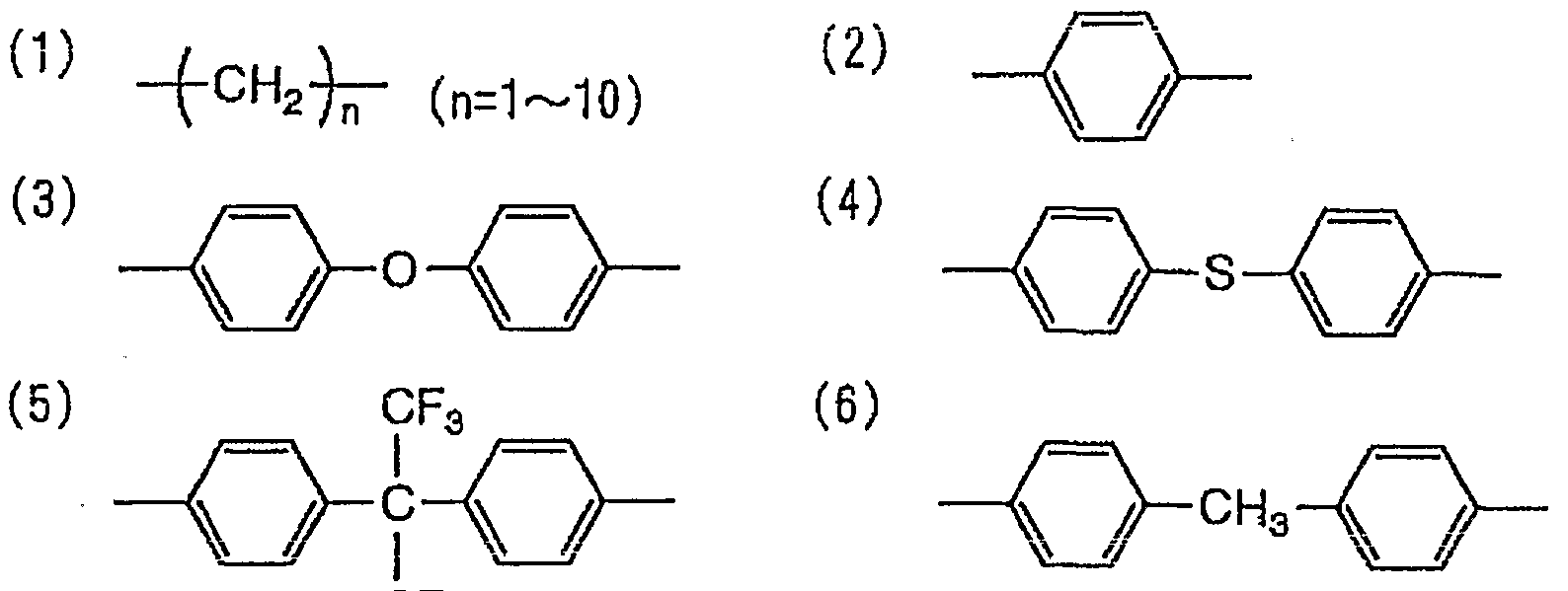
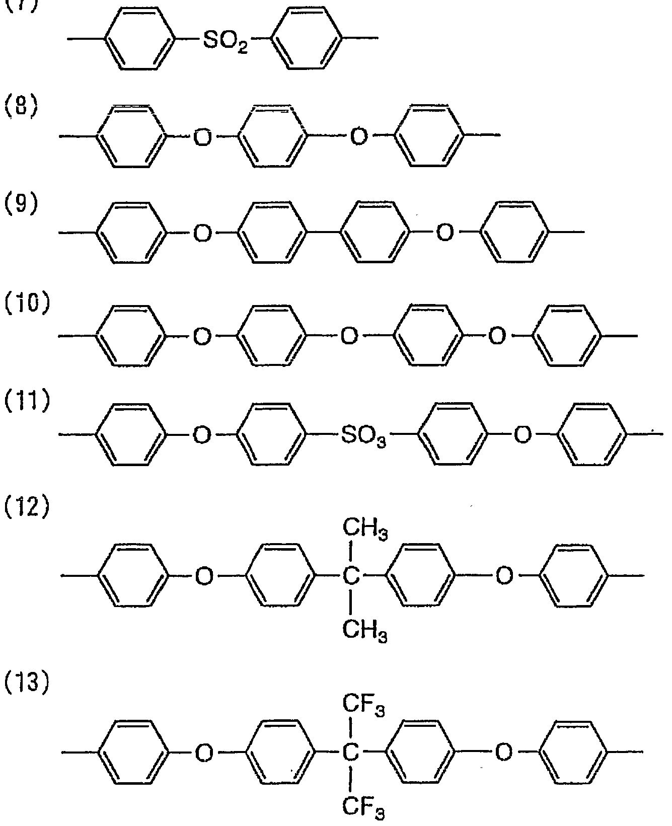
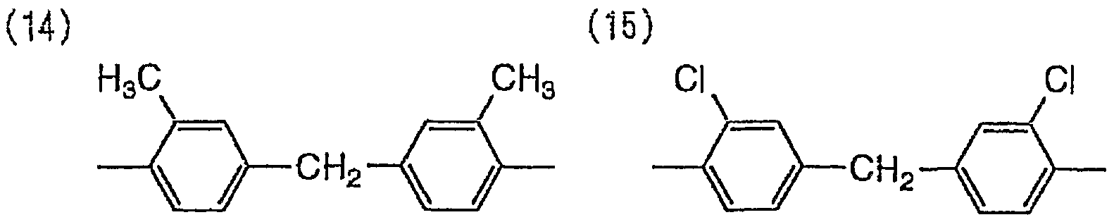
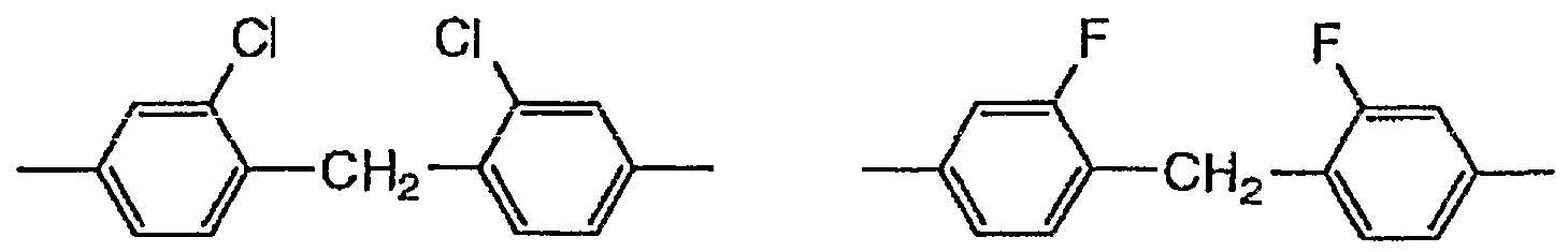
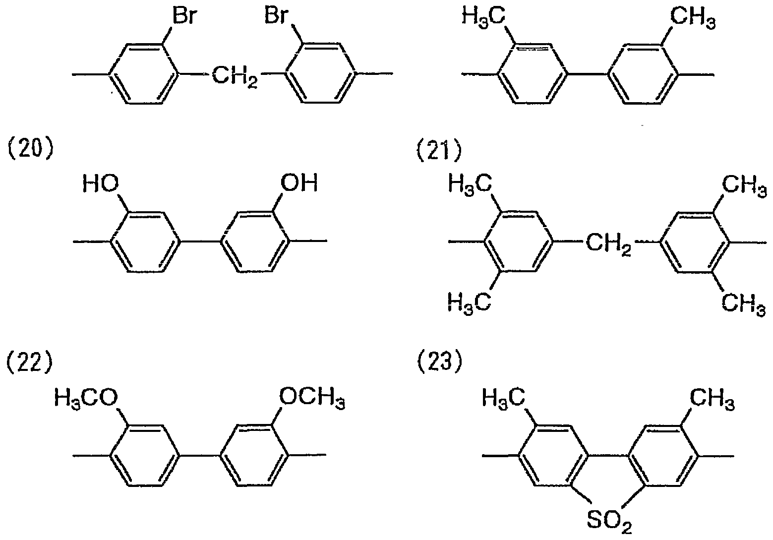
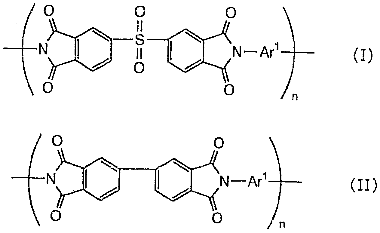
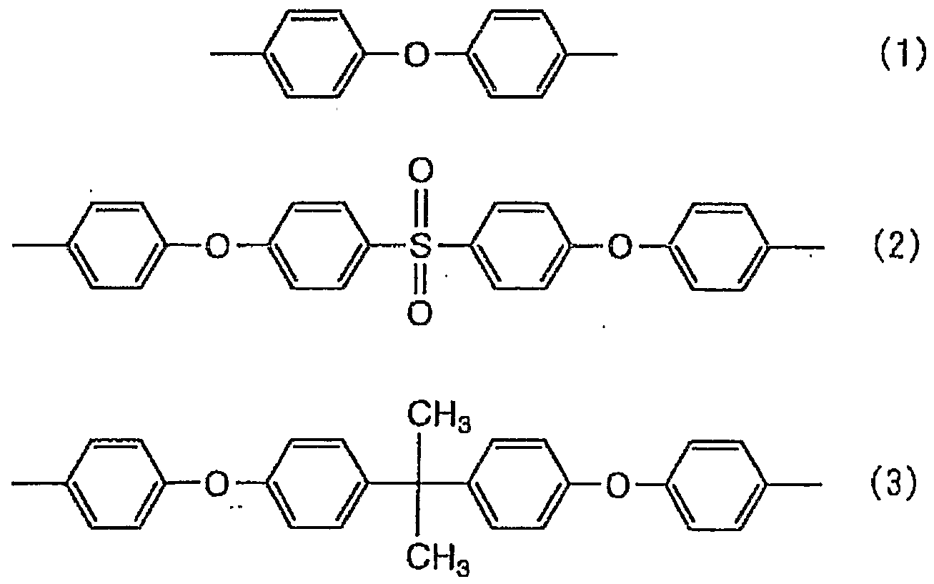

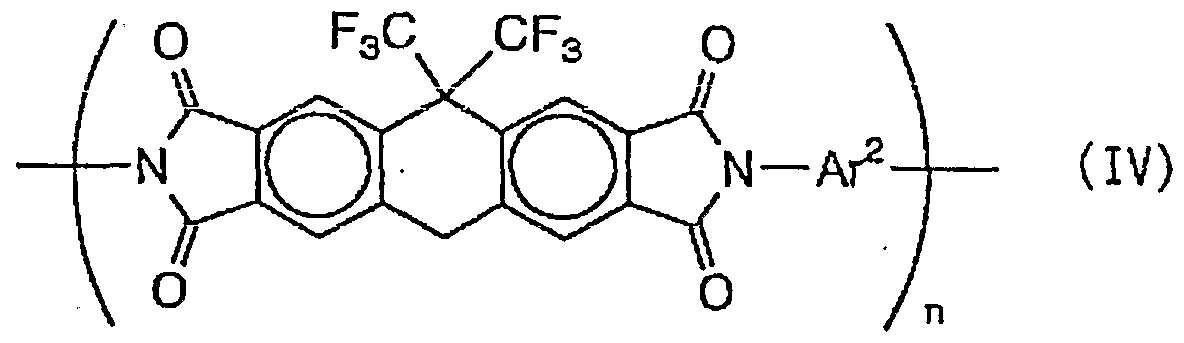
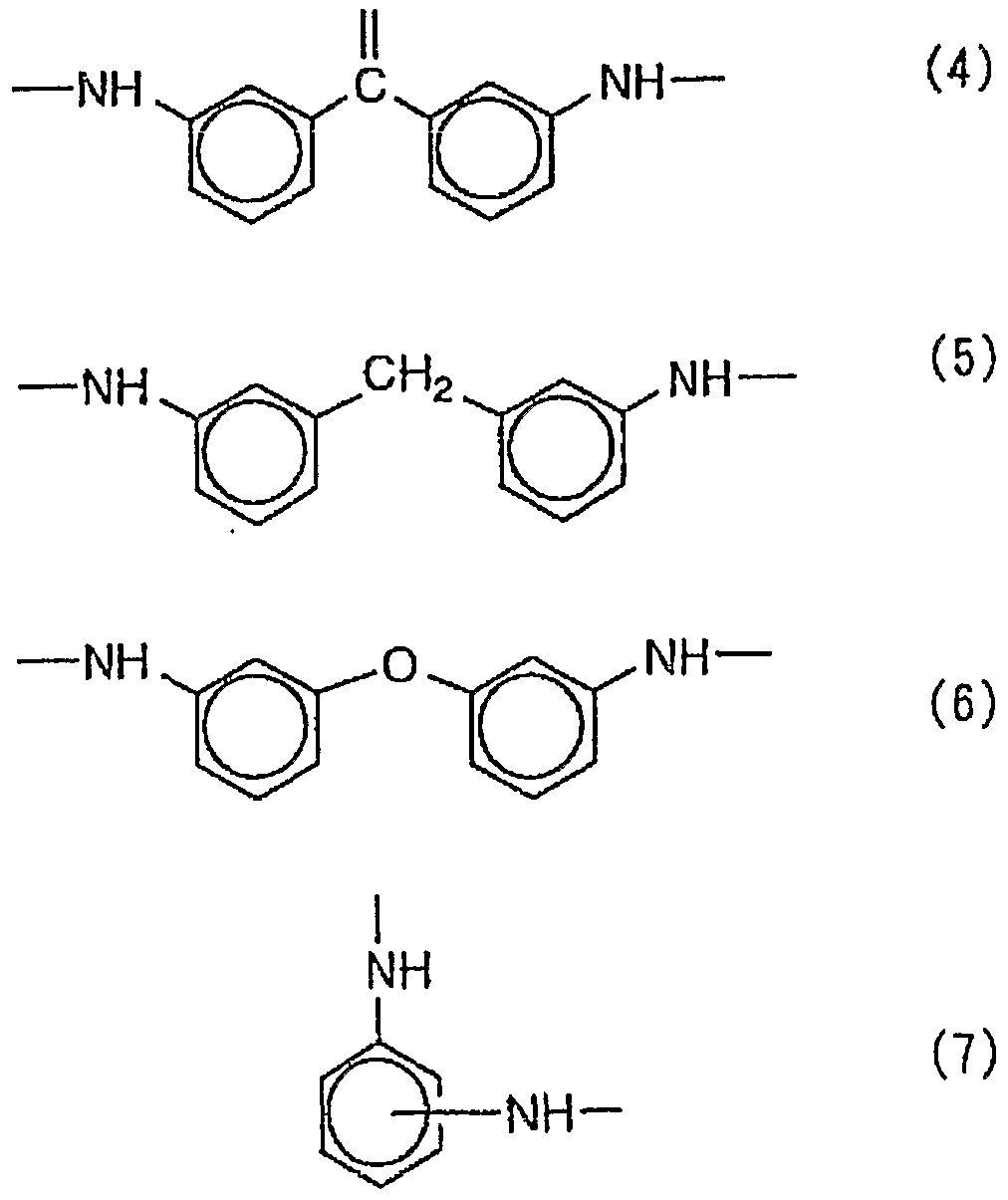


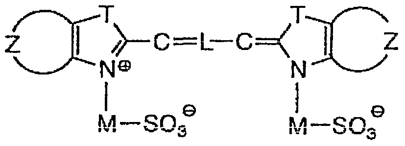


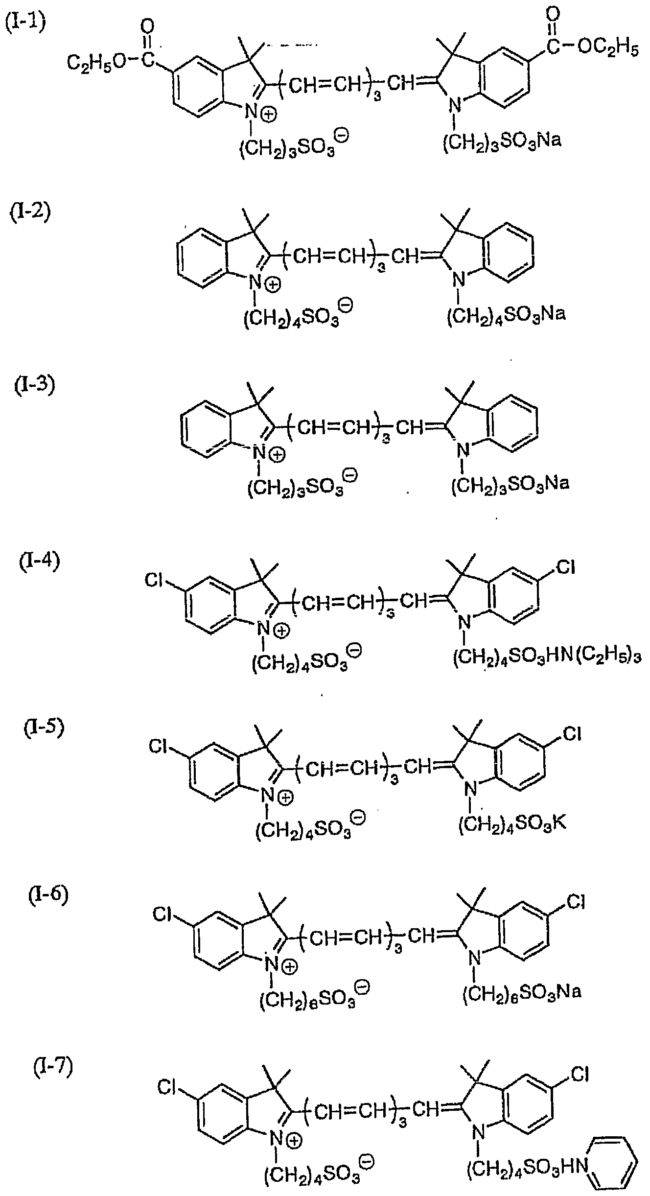
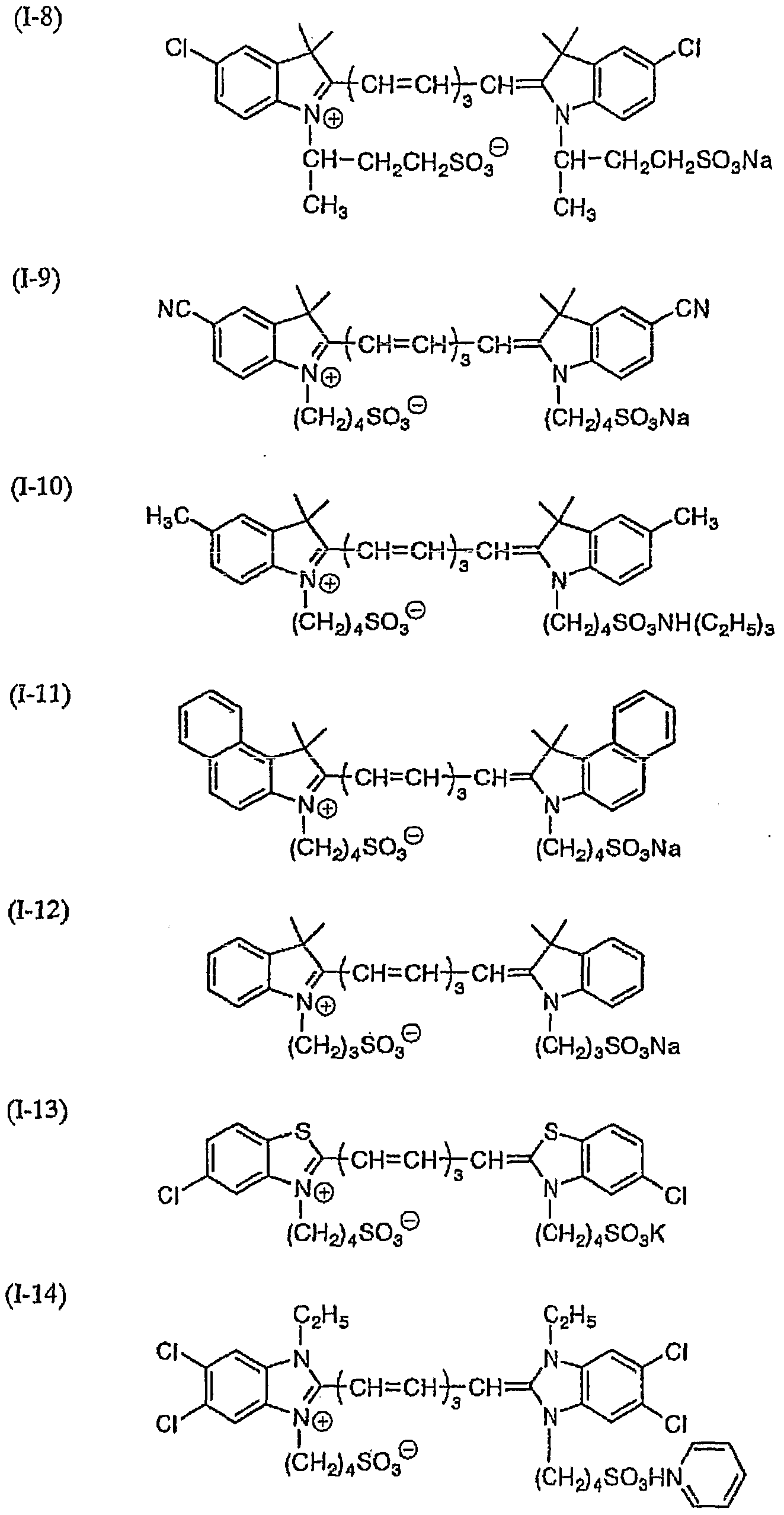


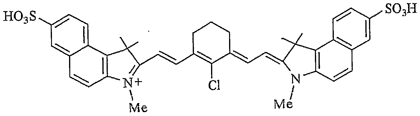
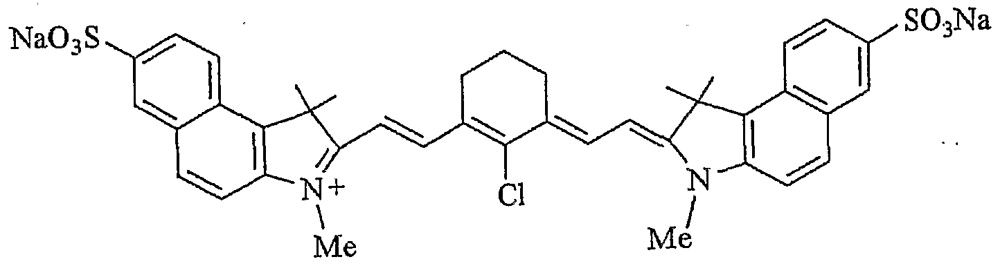
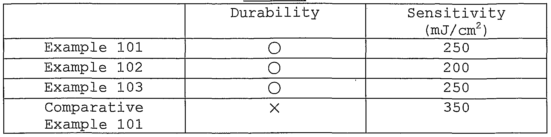
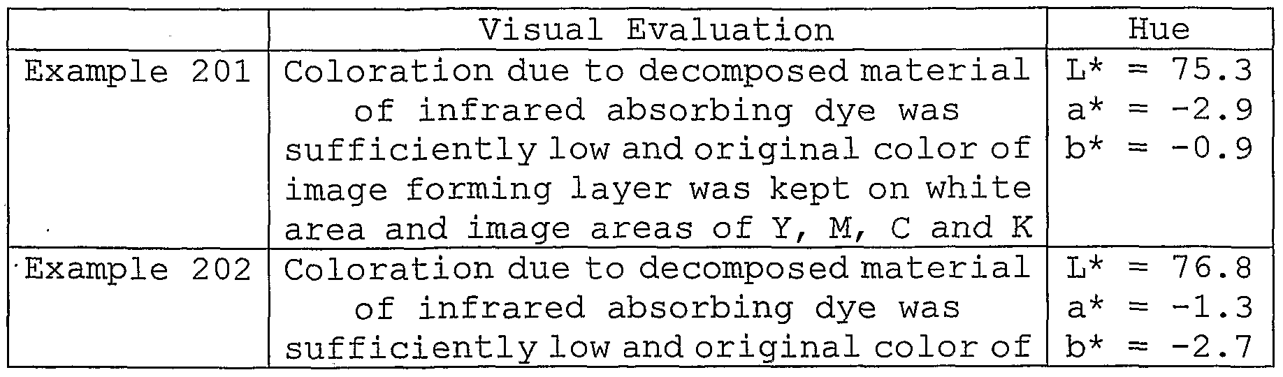
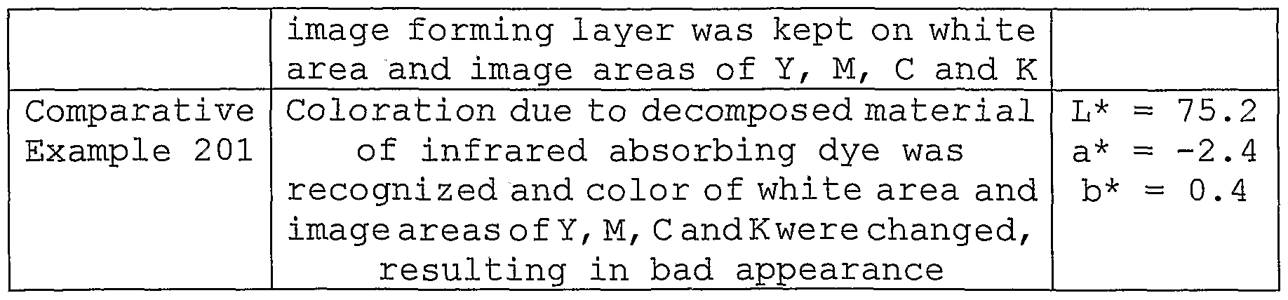
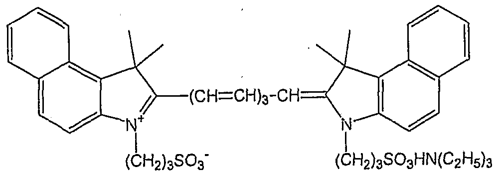
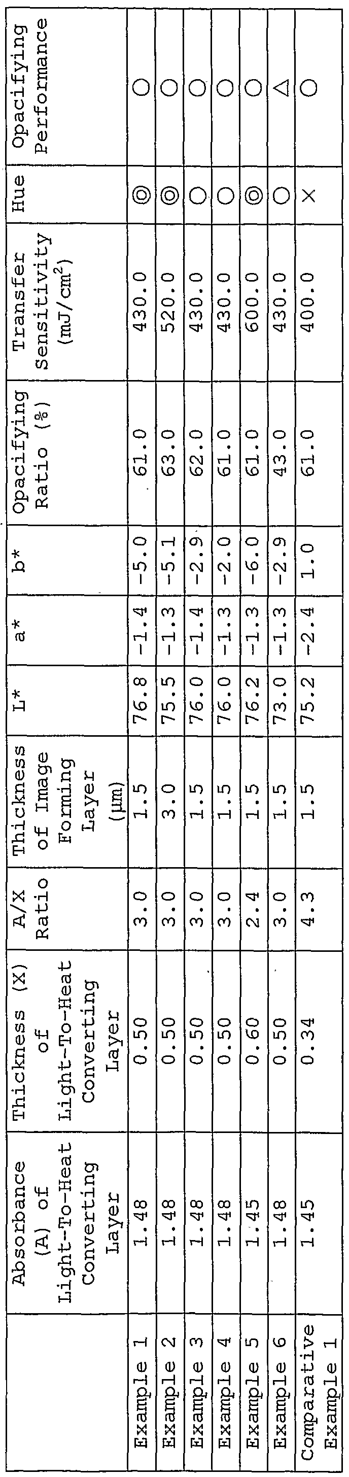
Claims
Priority Applications (2)
| Application Number | Priority Date | Filing Date | Title |
|---|---|---|---|
| US10/555,016 US20060204886A1 (en) | 2003-05-30 | 2004-05-28 | Heat transfer sheet, image forming material and image forming method |
| EP04735396A EP1628836A4 (en) | 2003-05-30 | 2004-05-28 | Heat transfer sheet, image forming material and image forming method |
Applications Claiming Priority (6)
| Application Number | Priority Date | Filing Date | Title |
|---|---|---|---|
| JP2003-155477 | 2003-05-30 | ||
| JP2003155477A JP2004351884A (en) | 2003-05-30 | 2003-05-30 | Thermal transfer sheet, image forming material and image forming method |
| JP2003175083A JP4007601B2 (en) | 2003-06-19 | 2003-06-19 | Multicolor image forming material |
| JP2003-175083 | 2003-06-19 | ||
| JP2003335449A JP2005096360A (en) | 2003-09-26 | 2003-09-26 | Thermal transfer recording material |
| JP2003-335449 | 2003-09-26 |
Publications (1)
| Publication Number | Publication Date |
|---|---|
| WO2004106083A1 true WO2004106083A1 (en) | 2004-12-09 |
Family
ID=33493934
Family Applications (1)
| Application Number | Title | Priority Date | Filing Date |
|---|---|---|---|
| PCT/JP2004/007767 Ceased WO2004106083A1 (en) | 2003-05-30 | 2004-05-28 | Heat transfer sheet, image forming material and image forming method |
Country Status (3)
| Country | Link |
|---|---|
| US (1) | US20060204886A1 (en) |
| EP (1) | EP1628836A4 (en) |
| WO (1) | WO2004106083A1 (en) |
Families Citing this family (6)
| Publication number | Priority date | Publication date | Assignee | Title |
|---|---|---|---|---|
| JP2007092030A (en) * | 2005-08-05 | 2007-04-12 | Rohm & Haas Electronic Materials Llc | Improved opaque coating |
| CN103054284B (en) * | 2012-12-31 | 2014-10-29 | 湖北联合天诚防伪技术股份有限公司 | Metallic coin stamped with holographic anti-counterfeiting pattern and manufacturing method thereof |
| KR20150092213A (en) * | 2013-12-26 | 2015-08-12 | 신에쯔 세끼에이 가부시키가이샤 | Quartz glass for wavelength conversion and producing method therefor |
| JP6388155B2 (en) * | 2014-09-18 | 2018-09-12 | 富士ゼロックス株式会社 | Image forming apparatus and image data processing apparatus |
| CN107297968A (en) * | 2016-04-15 | 2017-10-27 | 鸿富锦精密工业(深圳)有限公司 | Composite surface treatment method |
| EP3914967B1 (en) | 2020-01-20 | 2023-03-01 | Hewlett-Packard Development Company, L.P. | Liquid electrostatic inks and methods of printing |
Citations (1)
| Publication number | Priority date | Publication date | Assignee | Title |
|---|---|---|---|---|
| JP2002086938A (en) * | 2000-09-18 | 2002-03-26 | Konica Corp | Laser heat transfer film |
Family Cites Families (8)
| Publication number | Priority date | Publication date | Assignee | Title |
|---|---|---|---|---|
| JPH06328862A (en) * | 1993-05-07 | 1994-11-29 | Minnesota Mining & Mfg Co <3M> | Mass transferable donor ribbon used for thermal dye transfer image forming |
| EP0739751A3 (en) * | 1995-04-25 | 1997-10-22 | Fuji Photo Film Co Ltd | Image forming method |
| US6228555B1 (en) * | 1999-12-28 | 2001-05-08 | 3M Innovative Properties Company | Thermal mass transfer donor element |
| US6190827B1 (en) * | 2000-05-04 | 2001-02-20 | Eastman Kodak Company | Laser donor element |
| JP2001328354A (en) * | 2000-05-19 | 2001-11-27 | Fuji Photo Film Co Ltd | Thermal transfer sheet and method for thermal transfer recording |
| US6864033B2 (en) * | 2001-01-24 | 2005-03-08 | Fuji Photo Film Co., Ltd. | Multicolor image-forming material |
| US6667093B2 (en) * | 2001-04-19 | 2003-12-23 | Arkwright Incorporated | Ink-jet printable transfer papers for use with fabric materials |
| JP2004090287A (en) * | 2002-08-29 | 2004-03-25 | Fuji Photo Film Co Ltd | Multi-color imaging material and multi-color imaging method |
-
2004
- 2004-05-28 WO PCT/JP2004/007767 patent/WO2004106083A1/en not_active Ceased
- 2004-05-28 EP EP04735396A patent/EP1628836A4/en not_active Withdrawn
- 2004-05-28 US US10/555,016 patent/US20060204886A1/en not_active Abandoned
Patent Citations (1)
| Publication number | Priority date | Publication date | Assignee | Title |
|---|---|---|---|---|
| JP2002086938A (en) * | 2000-09-18 | 2002-03-26 | Konica Corp | Laser heat transfer film |
Non-Patent Citations (1)
| Title |
|---|
| See also references of EP1628836A4 * |
Also Published As
| Publication number | Publication date |
|---|---|
| EP1628836A4 (en) | 2006-11-02 |
| US20060204886A1 (en) | 2006-09-14 |
| EP1628836A1 (en) | 2006-03-01 |
Similar Documents
| Publication | Publication Date | Title |
|---|---|---|
| US6864033B2 (en) | Multicolor image-forming material | |
| US6946425B2 (en) | Multicolor image forming material and method for forming multicolor image | |
| US6579655B1 (en) | Laser-heat transfer recording method and image-receiving sheet | |
| US6879336B2 (en) | Laser thermal transfer recording method and apparatus therefor | |
| US6790492B2 (en) | Multi-color image-forming material and multi-color image-forming process | |
| US7112396B2 (en) | Multicolor image forming material | |
| US6911294B2 (en) | Multicolor image forming material and method of multicolor image formation | |
| US7097955B2 (en) | Multicolor image forming material and multicolor image forming method using the same | |
| US20060204886A1 (en) | Heat transfer sheet, image forming material and image forming method | |
| US7022453B2 (en) | Multicolor image-forming material and multicolor image-forming method | |
| US6830863B2 (en) | Multicolor image-forming material and method for forming multicolor image | |
| JP3425564B2 (en) | Multicolor image forming material and multicolor image forming method | |
| US6824845B2 (en) | Multicolor image-forming material and method for forming multicolor image | |
| US6856337B2 (en) | Multicolor image-forming method and multicolor image-forming material | |
| EP1288719A2 (en) | Image-forming material, image formation method and method for manufacturing color proof | |
| EP1369257B1 (en) | Multicolor image forming material | |
| US20030059707A1 (en) | Multicolor image-forming material and multicolor image-forming method | |
| US6953650B2 (en) | Multicolor image forming material | |
| EP1241017A2 (en) | Multicolor image-forming material | |
| JP2002362040A (en) | Thermal transfer sheet and multi-color imaging method | |
| JP2002356072A (en) | Material and method for forming multicolor image | |
| JP2003191654A (en) | Thermal transfer sheet, multi-color image forming material and method for forming multi-color image |
Legal Events
| Date | Code | Title | Description |
|---|---|---|---|
| AK | Designated states |
Kind code of ref document: A1 Designated state(s): AE AG AL AM AT AU AZ BA BB BG BR BW BY BZ CA CH CN CO CR CU CZ DE DK DM DZ EC EE EG ES FI GB GD GE GH GM HR HU ID IL IN IS KE KG KP KR KZ LC LK LR LS LT LU LV MA MD MG MK MN MW MX MZ NA NI NO NZ OM PG PH PL PT RO RU SC SD SE SG SK SL SY TJ TM TN TR TT TZ UA UG US UZ VC VN YU ZA ZM ZW |
|
| AL | Designated countries for regional patents |
Kind code of ref document: A1 Designated state(s): BW GH GM KE LS MW MZ NA SD SL SZ TZ UG ZM ZW AM AZ BY KG KZ MD RU TJ TM AT BE BG CH CY CZ DE DK EE ES FI FR GB GR HU IE IT LU MC NL PL PT RO SE SI SK TR BF BJ CF CG CI CM GA GN GQ GW ML MR NE SN TD TG |
|
| 121 | Ep: the epo has been informed by wipo that ep was designated in this application | ||
| WWE | Wipo information: entry into national phase |
Ref document number: 10555016 Country of ref document: US |
|
| WWE | Wipo information: entry into national phase |
Ref document number: 2004735396 Country of ref document: EP |
|
| WWP | Wipo information: published in national office |
Ref document number: 2004735396 Country of ref document: EP |
|
| WWP | Wipo information: published in national office |
Ref document number: 10555016 Country of ref document: US |
|
| WWW | Wipo information: withdrawn in national office |
Ref document number: 2004735396 Country of ref document: EP |