WO2004020196A1 - Method of manufacturing laminated body - Google Patents
Method of manufacturing laminated bodyInfo
- Publication number
- WO2004020196A1 WO2004020196A1 PCT/JP2003/010805 JP0310805W WO2004020196A1 WO 2004020196 A1 WO2004020196 A1 WO 2004020196A1 JP 0310805 W JP0310805 W JP 0310805W WO 2004020196 A1 WO2004020196 A1 WO 2004020196A1
- Authority
- WO
- WIPO (PCT)
- Prior art keywords
- laminate
- producing
- plate
- adhesive layer
- manufacturing
- Prior art date
- Legal status (The legal status is an assumption and is not a legal conclusion. Google has not performed a legal analysis and makes no representation as to the accuracy of the status listed.)
- Ceased
Links
Classifications
-
- B—PERFORMING OPERATIONS; TRANSPORTING
- B29—WORKING OF PLASTICS; WORKING OF SUBSTANCES IN A PLASTIC STATE IN GENERAL
- B29C—SHAPING OR JOINING OF PLASTICS; SHAPING OF MATERIAL IN A PLASTIC STATE, NOT OTHERWISE PROVIDED FOR; AFTER-TREATMENT OF THE SHAPED PRODUCTS, e.g. REPAIRING
- B29C66/00—General aspects of processes or apparatus for joining preformed parts
- B29C66/40—General aspects of joining substantially flat articles, e.g. plates, sheets or web-like materials; Making flat seams in tubular or hollow articles; Joining single elements to substantially flat surfaces
- B29C66/41—Joining substantially flat articles ; Making flat seams in tubular or hollow articles
- B29C66/45—Joining of substantially the whole surface of the articles
-
- B—PERFORMING OPERATIONS; TRANSPORTING
- B29—WORKING OF PLASTICS; WORKING OF SUBSTANCES IN A PLASTIC STATE IN GENERAL
- B29C—SHAPING OR JOINING OF PLASTICS; SHAPING OF MATERIAL IN A PLASTIC STATE, NOT OTHERWISE PROVIDED FOR; AFTER-TREATMENT OF THE SHAPED PRODUCTS, e.g. REPAIRING
- B29C65/00—Joining or sealing of preformed parts, e.g. welding of plastics materials; Apparatus therefor
- B29C65/02—Joining or sealing of preformed parts, e.g. welding of plastics materials; Apparatus therefor by heating, with or without pressure
- B29C65/14—Joining or sealing of preformed parts, e.g. welding of plastics materials; Apparatus therefor by heating, with or without pressure using wave energy, i.e. electromagnetic radiation, or particle radiation
- B29C65/1403—Joining or sealing of preformed parts, e.g. welding of plastics materials; Apparatus therefor by heating, with or without pressure using wave energy, i.e. electromagnetic radiation, or particle radiation characterised by the type of electromagnetic or particle radiation
- B29C65/1425—Microwave radiation
-
- B—PERFORMING OPERATIONS; TRANSPORTING
- B29—WORKING OF PLASTICS; WORKING OF SUBSTANCES IN A PLASTIC STATE IN GENERAL
- B29C—SHAPING OR JOINING OF PLASTICS; SHAPING OF MATERIAL IN A PLASTIC STATE, NOT OTHERWISE PROVIDED FOR; AFTER-TREATMENT OF THE SHAPED PRODUCTS, e.g. REPAIRING
- B29C65/00—Joining or sealing of preformed parts, e.g. welding of plastics materials; Apparatus therefor
- B29C65/02—Joining or sealing of preformed parts, e.g. welding of plastics materials; Apparatus therefor by heating, with or without pressure
- B29C65/14—Joining or sealing of preformed parts, e.g. welding of plastics materials; Apparatus therefor by heating, with or without pressure using wave energy, i.e. electromagnetic radiation, or particle radiation
- B29C65/1429—Joining or sealing of preformed parts, e.g. welding of plastics materials; Apparatus therefor by heating, with or without pressure using wave energy, i.e. electromagnetic radiation, or particle radiation characterised by the way of heating the interface
- B29C65/1435—Joining or sealing of preformed parts, e.g. welding of plastics materials; Apparatus therefor by heating, with or without pressure using wave energy, i.e. electromagnetic radiation, or particle radiation characterised by the way of heating the interface at least passing through one of the parts to be joined, i.e. transmission welding
-
- B—PERFORMING OPERATIONS; TRANSPORTING
- B29—WORKING OF PLASTICS; WORKING OF SUBSTANCES IN A PLASTIC STATE IN GENERAL
- B29C—SHAPING OR JOINING OF PLASTICS; SHAPING OF MATERIAL IN A PLASTIC STATE, NOT OTHERWISE PROVIDED FOR; AFTER-TREATMENT OF THE SHAPED PRODUCTS, e.g. REPAIRING
- B29C65/00—Joining or sealing of preformed parts, e.g. welding of plastics materials; Apparatus therefor
- B29C65/02—Joining or sealing of preformed parts, e.g. welding of plastics materials; Apparatus therefor by heating, with or without pressure
- B29C65/14—Joining or sealing of preformed parts, e.g. welding of plastics materials; Apparatus therefor by heating, with or without pressure using wave energy, i.e. electromagnetic radiation, or particle radiation
- B29C65/1477—Joining or sealing of preformed parts, e.g. welding of plastics materials; Apparatus therefor by heating, with or without pressure using wave energy, i.e. electromagnetic radiation, or particle radiation making use of an absorber or impact modifier
- B29C65/1483—Joining or sealing of preformed parts, e.g. welding of plastics materials; Apparatus therefor by heating, with or without pressure using wave energy, i.e. electromagnetic radiation, or particle radiation making use of an absorber or impact modifier coated on the article
-
- B—PERFORMING OPERATIONS; TRANSPORTING
- B29—WORKING OF PLASTICS; WORKING OF SUBSTANCES IN A PLASTIC STATE IN GENERAL
- B29C—SHAPING OR JOINING OF PLASTICS; SHAPING OF MATERIAL IN A PLASTIC STATE, NOT OTHERWISE PROVIDED FOR; AFTER-TREATMENT OF THE SHAPED PRODUCTS, e.g. REPAIRING
- B29C66/00—General aspects of processes or apparatus for joining preformed parts
- B29C66/01—General aspects dealing with the joint area or with the area to be joined
- B29C66/05—Particular design of joint configurations
- B29C66/10—Particular design of joint configurations particular design of the joint cross-sections
- B29C66/11—Joint cross-sections comprising a single joint-segment, i.e. one of the parts to be joined comprising a single joint-segment in the joint cross-section
- B29C66/112—Single lapped joints
- B29C66/1122—Single lap to lap joints, i.e. overlap joints
-
- B—PERFORMING OPERATIONS; TRANSPORTING
- B32—LAYERED PRODUCTS
- B32B—LAYERED PRODUCTS, i.e. PRODUCTS BUILT-UP OF STRATA OF FLAT OR NON-FLAT, e.g. CELLULAR OR HONEYCOMB, FORM
- B32B37/00—Methods or apparatus for laminating, e.g. by curing or by ultrasonic bonding
- B32B37/12—Methods or apparatus for laminating, e.g. by curing or by ultrasonic bonding characterised by using adhesives
- B32B37/1207—Heat-activated adhesive
-
- B—PERFORMING OPERATIONS; TRANSPORTING
- B29—WORKING OF PLASTICS; WORKING OF SUBSTANCES IN A PLASTIC STATE IN GENERAL
- B29C—SHAPING OR JOINING OF PLASTICS; SHAPING OF MATERIAL IN A PLASTIC STATE, NOT OTHERWISE PROVIDED FOR; AFTER-TREATMENT OF THE SHAPED PRODUCTS, e.g. REPAIRING
- B29C66/00—General aspects of processes or apparatus for joining preformed parts
- B29C66/70—General aspects of processes or apparatus for joining preformed parts characterised by the composition, physical properties or the structure of the material of the parts to be joined; Joining with non-plastics material
- B29C66/71—General aspects of processes or apparatus for joining preformed parts characterised by the composition, physical properties or the structure of the material of the parts to be joined; Joining with non-plastics material characterised by the composition of the plastics material of the parts to be joined
-
- B—PERFORMING OPERATIONS; TRANSPORTING
- B29—WORKING OF PLASTICS; WORKING OF SUBSTANCES IN A PLASTIC STATE IN GENERAL
- B29L—INDEXING SCHEME ASSOCIATED WITH SUBCLASS B29C, RELATING TO PARTICULAR ARTICLES
- B29L2009/00—Layered products
-
- B—PERFORMING OPERATIONS; TRANSPORTING
- B32—LAYERED PRODUCTS
- B32B—LAYERED PRODUCTS, i.e. PRODUCTS BUILT-UP OF STRATA OF FLAT OR NON-FLAT, e.g. CELLULAR OR HONEYCOMB, FORM
- B32B2310/00—Treatment by energy or chemical effects
- B32B2310/08—Treatment by energy or chemical effects by wave energy or particle radiation
- B32B2310/0806—Treatment by energy or chemical effects by wave energy or particle radiation using electromagnetic radiation
- B32B2310/0862—Treatment by energy or chemical effects by wave energy or particle radiation using electromagnetic radiation using microwave
Definitions
- the present invention relates to a method of manufacturing a laminate in which at least two plate-like bodies are bonded with an adhesive layer, and more particularly to a method of manufacturing a laminate in which plate-like bodies having different coefficients of thermal expansion are stacked.
- the method of laminating plate-like bodies by bonding can be broadly classified into two methods when focusing on the bonding temperature. There are two methods: 1) a bonding method at room temperature and 2) a bonding method by heating. In the production method 2), a thermoplastic resin, a thermosetting resin, or the like is used as an adhesive layer, and bonding is performed through a hot press crepe process.
- the manufacturing method of bonding at room temperature in the above 1) has a problem that it takes a long time to obtain an adhesive laminate and the productivity is low.
- Japanese Patent Application Laid-Open No. 7-32504 is an example of a method for producing a laminate using the hot press-plate clave of the above 2). According to the above publication, in claim 2,
- a glass plate or an acrylic resin plate and a polycarbonate resin plate are laminated via a urethane-based adhesive film, and the laminate is heated to 100 to 150 ° C in a reduced-pressure atmosphere to 1.5 kg /
- the thermal expansion coefficients of the glass plate, acrylic resin plate, and polycarbonate resin plate are different from each other, so a difference in expansion occurs due to heating, and after bonding, when cooled down to room temperature, warpage occurs due to the difference in expansion. There is.
- Japanese Patent Application Laid-Open No. H10-119184 discloses a transparent laminate of an inorganic glass plate and a polycarbonate plate with less warpage.
- This laminate is obtained by selecting an intermediate film with high viscosity and heating and pressurizing in an atmosphere.
- the entire laminate is heated because of the atmosphere heating. Therefore, due to the difference in the coefficient of thermal expansion between the inorganic glass plate and the polycarbonate plate due to heating, When the temperature drops to room temperature after bonding, warpage occurs due to the difference in expansion.
- heating efficiency is reduced because heating is not performed only for the adhesive layer.
- a shear stress acts on the bonding layer, and peeling occurs at the bonding interface. That is, in the above-described method for manufacturing a laminate, only heating the entire laminate is disclosed, and no means for efficiently heating the adhesive layer is shown.
- the present invention provides a method for producing a laminate in which an adhesive layer is preferentially and efficiently heated and adhered. Further, the present invention provides a method for manufacturing a laminated body capable of suppressing warpage and peeling at an adhesive interface caused by a difference in thermal expansion coefficient. Disclosure of the invention
- a first characteristic means of the method for producing a laminate according to the present invention is a method for producing a laminate in which at least two plate-like bodies are adhered with an adhesive layer, wherein the adhesive layer has a higher dielectric loss than the plate-like body.
- the method is characterized in that the adhesive layer is made of a material having a high rate, and the adhesive layer is irradiated with microwaves and heated so that the adhesive layer can be bonded, and the at least two plate-like bodies are bonded and laminated.
- a second feature of the method of manufacturing a laminate according to the present invention is that, in the first feature, the plate-like bodies have different coefficients of thermal expansion.
- a third aspect of the method for manufacturing a laminate according to the present invention is that, in the first aspect, the adhesive layer is a thermoplastic resin film.
- a fourth aspect of the method for producing a laminate according to the present invention is the above-mentioned third aspect, wherein the adhesive layer is a polyurethane film, a polybutyral film, or an ethylene-vinyl acetate copolymer film. It is in.
- a fifth aspect of the method for producing a laminate according to the present invention is that, in the first aspect, the two plate-like bodies are made of inorganic glass and organic resin.
- a sixth aspect of the method for producing a laminate according to the present invention is that, in the fifth aspect, the organic resin is an acryl resin or a polycarbonate resin.
- a seventh characteristic means of the method for manufacturing a laminate according to the present invention is that, in the first characteristic means, the laminate is further adhered while being pressed by a pressing means.
- An eighth feature of the method for manufacturing a laminate according to the present invention is the seventh feature, wherein The pressurizing means is a mechanical press.
- the ninth characteristic means of the method for manufacturing a laminate according to the present invention is the method according to the seventh characteristic means, wherein the pressurizing is performed by putting a bag containing the laminate in a champer and degassing under reduced pressure. The point is that gas is sealed in the chamber and pressurized.
- a tenth characteristic means of the method for manufacturing a laminate according to the present invention is the above-mentioned first characteristic means, wherein the microwave is an electromagnetic wave of 1 to 300 GHz.
- the adhesive layer can be heated preferentially and efficiently by setting the dielectric loss factor of the adhesive layer to be higher than the dielectric loss factor of the plate-shaped body. Further, since the temperature rise of the plate-like body can be suppressed, thermal expansion during bonding can be suppressed.
- FIG. 1 is a schematic view of an apparatus for manufacturing a laminate that can be used in the present invention
- FIG. 2 is a cross-sectional view of the laminate obtained by the present invention
- FIG. 3 is a diagram showing the relationship between the dielectric loss angle and the relative permittivity of a dielectric
- FIG. 4 is a diagram schematically illustrating a gyrotron oscillator.
- FIG. 5 is a graph showing the temperature rise in the temperature rise test
- FIG. 6 is a diagram illustrating a state in which a strain gauge is attached to a laminated polycarbonate plate.
- FIG. 1 is a schematic view of an oscillation device 2 for manufacturing a laminated body 1.
- FIG. 2 is a configuration diagram of the laminated body 1.
- the configuration of the oscillating device 2 includes a chamber 1, an oscillator 4, and a waveguide 5.
- the microwave generated by the oscillator 4 is guided to the chamber 3 by the waveguide 5.
- the adhesive layer 12 is preferentially heated by the microwave guided into the champers, and the laminate 1 can be adhered.
- the oscillator 4 is a device that generates a microwave. Microwave to dielectric (insulator) , Molecular vibration occurs in the dielectric ⁇ ⁇ due to the microwave electric field. Vibration friction is generated by this molecular vibration, and the dielectric itself generates heat. Since molecular vibrations occur throughout the dielectric, the heat generation is uniform.
- the calorific value of a dielectric is proportional to the microwave electric field, frequency, and a physical property called dielectric loss factor. That is, the calorific value increases as the dielectric has a higher dielectric loss factor. Therefore, when a material having a large dielectric loss factor of the adhesive layer is selected with respect to the dielectric loss factor of the adherend, the amount of heat generated by the adhesive layer is increased with respect to the amount of heat generated by the adherend.
- the dielectric loss factor is represented by the product of the relative dielectric constant, which is a physical property value, and the dielectric loss angle.
- Figure 3 shows the relationship between the dielectric and other loss angles and the relative permittivity of the dielectric. Fig. 3 shows the case when the frequency is 2.45 GHz. The amount of heat generated increases toward the upper right of Fig. 3. The figure also shows the half depth. Half-depth is the distance at which microwaves travel through a dielectric and the energy of the microwaves decay in half. The shallower half-depth indicates higher calorific value.
- Microwave oscillators used for heating include: 1) magnetron (practical frequency range is 1 to 200 GHz :), 2) klystron (practical frequency range is about: ⁇ 100 GHz), 3) gyrotron ( The frequency ranges from 11 to 300 GHz). Both are oscillators used for sintering ceramics. When the frequency increases in all of 1), 2) and 3), the output cannot be increased. However, compared to 1) and 2), gyrotron oscillators have a larger resonance space called cavity, and can generate higher frequencies. In addition, since the radius of the electron beam can be increased, a decrease in output can be suppressed. Therefore, a gyrotron is the most desirable microwave oscillator.
- Fig. 4 shows an outline of the gyrotron oscillator.
- the gyrotron is an electron tube capable of high-efficiency, high-power oscillation using the principle of oscillation called the electron cyclotron resonance maser (CRM).
- the gyrotron 41 has a cavity resonator 45 that oscillates an electromagnetic wave as a center. Be composed.
- As the electron gun a magneto-injection electron gun is used.
- a gyroscopic cylindrical electron beam is generated by a magneto-injection electron gun. Incident on the cavity resonator. The rotational kinetic energy of the incident electron beam is converted into electromagnetic wave energy by the CRM in a very limited space inside the cylindrical resonator to which a strong magnetic field is applied.
- a plate-like adhesive layer is laminated, and the microwave is irradiated to preferentially generate heat, and further, pressure is applied to adhere.
- the material of the adhesive layer has a higher dielectric loss factor than that of the plate. Since the dielectric loss factor of the adhesive layer is larger than the dielectric loss factor of the plate, the adhesive layer can be preferentially heated. Warpage due to the resulting difference in shrinkage can be reduced, and peeling at the bonding interface can be suppressed.
- the glass plate, the polycarbonate plate, and the polyurethane film were irradiated with microwaves, and the temperature was measured to determine whether only the polyurethane film could be heated to the softening point temperature (about 90 ° C).
- glass plate 1 1 (1 50 X 1 50 X 4 mm), polyurethane film 1 2 (1 50 X 15 0 X 0.7 mm), and polycarbonate plate 1 3 (1 50 X (150 ⁇ 2 mm), placed on the stage 31 in the chamber 13, and irradiated with microwaves. Each temperature was measured using a K-type thermocouple.
- Fig. 5 shows the results. From this, it was found that the polyurethane film was heated to around the softening point at which tackiness occurs (about 90 ° C). On the other hand, the glass plate is about 40 ° C, and the polycarbonate plate is about 55 ° C, which is about 20 to 3 at room temperature (about 20 ° C). It was found that the temperature was suppressed by about o ° c. From this, it was confirmed that the thermal expansion of the glass plate and the polycarbonate plate could be suppressed.
- the adhesive layer can be preferentially and efficiently heated by irradiating the microwave to the laminate of the glass plate, the polyurethane film, and the polycarbonate plate.
- the inside of the bag was evacuated to about 48 Pa, and while maintaining the pressure in the chamber at about 0.58 MPa, microwaves were irradiated to heat the adhesive layer of the laminate. Heat to about the softening point of the polyurethane film (approximately 90 ° C) within 10 minutes (output: lkW), then hold for 15 minutes (output: about 0.8 kW) From room temperature to room temperature.
- a laminate of the glass plate Z and the polyurethane film polycarbonate plate was obtained.
- the residual stress of the laminated body of the glass plate / polyurethane film / polycarbonate plate obtained by the above method was measured using a strain gauge.
- a residual stress was measured by attaching a strain gauge to the polycarbonate plate side. This is because the polycarbonate plate side is liable to crack due to residual stress, and therefore it is desired that the residual stress on the polycarbonate side be small. The measurement will be described below.
- a strain gauge is a device that converts strain into an electrical signal and outputs it when strain occurs in the object to be measured.
- the strain gauge used this time is a uniaxial gauge and measures one-way strain.
- the strain gauge was attached to each side of the polycarbonate plate, the strain in the direction parallel to each side was measured, and the residual stress was calculated.
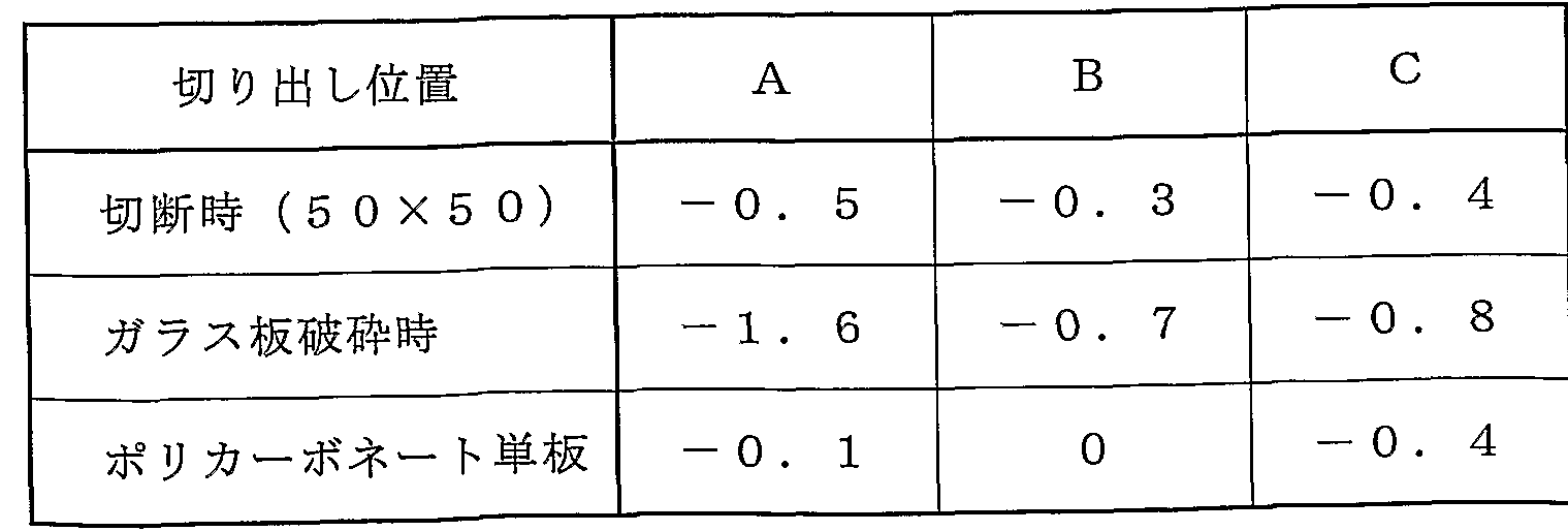
- a state where the strain gauge 6 is attached to the polycarbonate plate 13 side of the laminate 1 Fig. 6 shows a plan view (a) and a side view (b). First, a portion to which the strain gauge is attached is cut out in a size of 50 ⁇ 5 O mm. Next, the glass plate is crushed for the sample with the strain gauge cut out to remove the stress caused by the glass plate. Finally, the polyurethane film was peeled off, and the stress acting on the polycarbonate plate was measured.
- Tables 1 and 2 show the residual stress of the polycarbonate plate measured at a total of three points (A, B, and C) in each of the laminate bonded by the bonding method and the laminate bonded by using the autoclave.
- the laminate bonded by using an autoclave was obtained by the same manufacturing method as described above, except that the heating means of the adhesive layer was by the autocrepe.
- the dimensions are 740 x 65 O mm, and the thickness of each of the glass plate / polyurethane film / polycarbonate plate is the same as that of the laminate using microwaves.
- the size of the laminate (150 X 15 O mm) bonded using a microphone mouth wave and the size of the laminate (740 X 6.5 mm) bonded using an autoclave are different, but the residual stress is polycarbonate. This is due to the difference in thermal expansion coefficient between the plate and the glass plate. Therefore, they can be compared regardless of their size.
- the method for producing a laminate according to the present invention relates to the production of a laminate in which at least two plate-like bodies are bonded to each other with an adhesive layer, and particularly to the production of a laminate in which plate-like bodies having different thermal expansion coefficients are laminated. Applicable to
Landscapes
- Engineering & Computer Science (AREA)
- Mechanical Engineering (AREA)
- Physics & Mathematics (AREA)
- Electromagnetism (AREA)
- Health & Medical Sciences (AREA)
- Toxicology (AREA)
- Laminated Bodies (AREA)
Abstract
Description
明 細 書 積層体の製造方法 技術分野 Description Manufacturing method of laminated body Technical field
本発明は、 少なく とも二枚からなる板状体を接着層にて接着する積層体の製造 に関し、 特に熱膨張率の異なる板状体を積層した積層体の製造方法に関する。 背景技術 The present invention relates to a method of manufacturing a laminate in which at least two plate-like bodies are bonded with an adhesive layer, and more particularly to a method of manufacturing a laminate in which plate-like bodies having different coefficients of thermal expansion are stacked. Background art
板状体を接着により積層する方法としては、 接着温度に着目すると二つに大別 できる。 1 ) 常温で接着する製造方法、 2 ) 加熱して接着する製造方法の二通り である。 2 ) の製造方法では、 接着層として熱可塑性樹脂や熱硬化性樹脂等を用 い、 熱プレスゃォートクレープの工程を経て接着する方法である。 The method of laminating plate-like bodies by bonding can be broadly classified into two methods when focusing on the bonding temperature. There are two methods: 1) a bonding method at room temperature and 2) a bonding method by heating. In the production method 2), a thermoplastic resin, a thermosetting resin, or the like is used as an adhesive layer, and bonding is performed through a hot press crepe process.
上記 1 ) の常温で接着する製造方法では、 接着積層体が得られるまでに長時間 を要し、 生産性が低いという問題がある。 The manufacturing method of bonding at room temperature in the above 1) has a problem that it takes a long time to obtain an adhesive laminate and the productivity is low.
上記 2 )の熱プレスゃォートクレーブを用いた積層体の製造方法の一例として、 特開平 7— 3 2 3 5 0 4号公報がある。 上記公報によると、 請求項 2において、 Japanese Patent Application Laid-Open No. 7-32504 is an example of a method for producing a laminate using the hot press-plate clave of the above 2). According to the above publication, in claim 2,
「ガラス板又はアクリル系樹脂板とポリカーボネート樹脂板とをウレタン系接着 フィルムを介して積層し、 この積層体を減圧雰囲気中で 1 0 0〜 1 5 0 °Cに加熱 して 1 . 5 k g / c m2以下の圧力で圧着することを特徴とする透明複合板の製 造方法」 が開示されている。 `` A glass plate or an acrylic resin plate and a polycarbonate resin plate are laminated via a urethane-based adhesive film, and the laminate is heated to 100 to 150 ° C in a reduced-pressure atmosphere to 1.5 kg / A method for producing a transparent composite plate, characterized by performing pressure bonding at a pressure of 2 cm 2 or less ”.
上記方法では、 ガラス板もしくはアクリル系樹脂板、 ポリカーボネート樹脂板 の熱膨張率がそれぞれ異なるため、 加熱による膨張差が生じ、 接着後、 室温まで 冷却すると膨張の差の分だけ反りが発生するという問題がある。 In the above method, the thermal expansion coefficients of the glass plate, acrylic resin plate, and polycarbonate resin plate are different from each other, so a difference in expansion occurs due to heating, and after bonding, when cooled down to room temperature, warpage occurs due to the difference in expansion. There is.
そこで、 特開平 1 0— 1 1 9 1 8 4号公報には、 反りの少ない無機ガラス板と ポリカーボネ一ト板との透明積層体が開示されている。 この積層体は、 中間膜の 粘性が高いものを選び、 雰囲気加熱と加圧により得られる。 しかし、 この方法で は雰囲気加熱であるため積層体全体が加熱される。 そのため、 加熱により無機ガ ラス板とポリカーボネート板はそれぞれの熱膨張率の違いから、 熱膨張による差 が生じ、 接着後、 室温まで温度が下がると膨張の差の分だけ反りが発生する。 ま た、 接着層のみの加熱でないため、 加熱効率は落ちる。 そして、 接着した後に接 着層にせん断応力が作用し、 接着界面で剥離が起こるという問題もある。 , つまり、 上述の積層体の製造方法では、 積層体全体を加熱することのみが開示 され、 接着層を効率的に加熱する手段は示されていない。 Therefore, Japanese Patent Application Laid-Open No. H10-119184 discloses a transparent laminate of an inorganic glass plate and a polycarbonate plate with less warpage. This laminate is obtained by selecting an intermediate film with high viscosity and heating and pressurizing in an atmosphere. However, in this method, the entire laminate is heated because of the atmosphere heating. Therefore, due to the difference in the coefficient of thermal expansion between the inorganic glass plate and the polycarbonate plate due to heating, When the temperature drops to room temperature after bonding, warpage occurs due to the difference in expansion. In addition, heating efficiency is reduced because heating is not performed only for the adhesive layer. There is also a problem that after the bonding, a shear stress acts on the bonding layer, and peeling occurs at the bonding interface. That is, in the above-described method for manufacturing a laminate, only heating the entire laminate is disclosed, and no means for efficiently heating the adhesive layer is shown.
本発明では、 接着層を優先的 ·効率的に加熱して接着する積層体の製造方法を 提供する。 さらに熱膨張率の違いから生じる反りや接着界面での剥離を抑えるこ とのできる積層体の製造方法を提供する。 発明の開示 The present invention provides a method for producing a laminate in which an adhesive layer is preferentially and efficiently heated and adhered. Further, the present invention provides a method for manufacturing a laminated body capable of suppressing warpage and peeling at an adhesive interface caused by a difference in thermal expansion coefficient. Disclosure of the invention
本発明に係る積層体の製造方法の第 1特徴手段は、 少なく とも二枚の板状体を 接着層にて接着した積層体の製造方法において、 前記接着層は前記板状体より誘 電損率が大きな材料からなり、 前記接着層へマイクロ波を照射し加熱することで 前記接着層を接着可能な状態として、 前記少なく とも二枚の板状体を接着し積層 する点にある。 A first characteristic means of the method for producing a laminate according to the present invention is a method for producing a laminate in which at least two plate-like bodies are adhered with an adhesive layer, wherein the adhesive layer has a higher dielectric loss than the plate-like body. The method is characterized in that the adhesive layer is made of a material having a high rate, and the adhesive layer is irradiated with microwaves and heated so that the adhesive layer can be bonded, and the at least two plate-like bodies are bonded and laminated.
本発明に係る積層体の製造方法の第 2特徴手段は、上記第 1特徴手段において、 前記板状体の熱膨張率が異なるものである点にある。 A second feature of the method of manufacturing a laminate according to the present invention is that, in the first feature, the plate-like bodies have different coefficients of thermal expansion.
本発明に係る積層体の製造方法の第 3特徴手段は、上記第 1特徴手段において、 前記接着層は、 熱可塑性樹脂膜である点にある。 A third aspect of the method for manufacturing a laminate according to the present invention is that, in the first aspect, the adhesive layer is a thermoplastic resin film.
本発明に係る積層体の製造方法の第 4特徴手段は、上記第 3特徴手段において、 前記接着層は、 ポリウレタン膜、 ポリビュルプチラール膜、 またはエチレン一酢 酸ビニル共重合体膜である点にある。 A fourth aspect of the method for producing a laminate according to the present invention is the above-mentioned third aspect, wherein the adhesive layer is a polyurethane film, a polybutyral film, or an ethylene-vinyl acetate copolymer film. It is in.
本発明に係る積層体の製造方法の第 5特徴手段は、上記第 1特徴手段において、 前記二枚の板状体は、 無機ガラスおょぴ有機樹脂よりなる点にある。 A fifth aspect of the method for producing a laminate according to the present invention is that, in the first aspect, the two plate-like bodies are made of inorganic glass and organic resin.
本発明に係る積層体の製造方法の第 6特徴手段は、上記第 5特徴手段において、 前記有機樹脂は、 ァクリル樹脂またはポリカーボネート樹脂である点にある。 本発明に係る積層体の製造方法の第 7特徴手段は、上記第 1特徴手段において、 さらに前記積層体を加圧手段で加圧しながら接着する点にある。 A sixth aspect of the method for producing a laminate according to the present invention is that, in the fifth aspect, the organic resin is an acryl resin or a polycarbonate resin. A seventh characteristic means of the method for manufacturing a laminate according to the present invention is that, in the first characteristic means, the laminate is further adhered while being pressed by a pressing means.
本発明に係る積層体の製造方法の第 8特徴手段は、上記第 7特徴手段において、 前記加圧手段は、 機械的プレスである点にある。 An eighth feature of the method for manufacturing a laminate according to the present invention is the seventh feature, wherein The pressurizing means is a mechanical press.
本発明に係る積層体の製造方法の第 9特徴手段は、上記第 7特徴手段において、 前記加圧は、 チャンパ一内に前記積層体を収めたバッグを入れて減圧脱気し、 さ らに前記チャンバ一内に気体を封入し与圧して行う点にある。 The ninth characteristic means of the method for manufacturing a laminate according to the present invention is the method according to the seventh characteristic means, wherein the pressurizing is performed by putting a bag containing the laminate in a champer and degassing under reduced pressure. The point is that gas is sealed in the chamber and pressurized.
本発明に係る積層体の製造方法の第 1 0特徴手段は、 上記第 1特徴手段におい て、 前記マイクロ波は、 1〜 3 0 0 G H zの電磁波である点にある。 A tenth characteristic means of the method for manufacturing a laminate according to the present invention is the above-mentioned first characteristic means, wherein the microwave is an electromagnetic wave of 1 to 300 GHz.
つまり、 本発明の特徴手段によれば、 接着層の誘電損率を板状体の誘電損率よ り大きなものとすることにより、 接着層を優先的 ·効率的に加熱することができ る。 また、 板状体の昇温を抑えることができるため、 接着時における熱膨張を抑 えることができる。 That is, according to the characteristic means of the present invention, the adhesive layer can be heated preferentially and efficiently by setting the dielectric loss factor of the adhesive layer to be higher than the dielectric loss factor of the plate-shaped body. Further, since the temperature rise of the plate-like body can be suppressed, thermal expansion during bonding can be suppressed.
その結果、 接着後の冷却時における熱収縮の量が減り、 反りを低減することが できる。 また、 接着界面での剥離を抑えることのできる積層体が得られる。 図面の簡単な説明 As a result, the amount of heat shrinkage during cooling after bonding is reduced, and warpage can be reduced. Further, a laminate that can suppress peeling at the bonding interface can be obtained. BRIEF DESCRIPTION OF THE FIGURES
第 1図は、 本発明に用いうる積層体を製造する装置の概略図であり、 第 2図は、 本発明により得られる積層体の断面図であり、 FIG. 1 is a schematic view of an apparatus for manufacturing a laminate that can be used in the present invention, and FIG. 2 is a cross-sectional view of the laminate obtained by the present invention;
第 3図は、 誘電体における誘電他損失角と比誘電率の関係を示す図であり、 第 4図は、 ジャイロ トロン発振器の概略を説明する図であり、 FIG. 3 is a diagram showing the relationship between the dielectric loss angle and the relative permittivity of a dielectric, and FIG. 4 is a diagram schematically illustrating a gyrotron oscillator.
第 5図は、 昇温テストにおける温度上昇を示すグラフであり、 FIG. 5 is a graph showing the temperature rise in the temperature rise test,
第 6図は、 ひずみゲージを積層体のポリカーボネート板に貼り付けた様子を説 明する図である。 発明を実施するための最良の形態 FIG. 6 is a diagram illustrating a state in which a strain gauge is attached to a laminated polycarbonate plate. BEST MODE FOR CARRYING OUT THE INVENTION
第 1図は、 積層体 1を製造する発振装置 2の概略図である。 また、 第 2図は積 層体 1の構成図である。 発振装置 2の構成としては、 チャンバ一 3、 発振器 4、 導波管 5とからなる。 発振器 4より発生するマイクロ波は、 導波管 5によりチヤ ンパー 3へ導かれる。 チャンパ一内へ導かれたマイクロ波により、 接着層 1 2が 優先的に加熱され、 積層体 1を接着することができる。 FIG. 1 is a schematic view of an oscillation device 2 for manufacturing a laminated body 1. FIG. 2 is a configuration diagram of the laminated body 1. The configuration of the oscillating device 2 includes a chamber 1, an oscillator 4, and a waveguide 5. The microwave generated by the oscillator 4 is guided to the chamber 3 by the waveguide 5. The adhesive layer 12 is preferentially heated by the microwave guided into the champers, and the laminate 1 can be adhered.
発振器 4は、 マイクロ波を発生する装置である。 マイクロ波を誘電体 (絶縁体) に照射すると、 誘電体內部でマイクロ波の電界により分子振動が起こる。 この分 子振動により振動摩擦が生じ、 誘電体自体が発熱する。 分子振動は誘電体全体で 起こるため、 発熱は均一なものとなる。 The oscillator 4 is a device that generates a microwave. Microwave to dielectric (insulator) , Molecular vibration occurs in the dielectric 電 界 due to the microwave electric field. Vibration friction is generated by this molecular vibration, and the dielectric itself generates heat. Since molecular vibrations occur throughout the dielectric, the heat generation is uniform.
誘電体の発熱量は、 マイクロ波の電界、 周波数、 そして誘電体の誘電損率と呼 ばれる物性値に比例する。つまり、誘電損率の高い誘電体ほど発熱量が多くなる。 そのため、 被接着体の誘電損率に対して、 接着層の誘電損率が大きいものを選択 すると、 被接着体の発熱量に対して、 接着層の発熱量が多くなる。 The calorific value of a dielectric is proportional to the microwave electric field, frequency, and a physical property called dielectric loss factor. That is, the calorific value increases as the dielectric has a higher dielectric loss factor. Therefore, when a material having a large dielectric loss factor of the adhesive layer is selected with respect to the dielectric loss factor of the adherend, the amount of heat generated by the adhesive layer is increased with respect to the amount of heat generated by the adherend.
ここで誘電損率は、 物性値である比誘電率と誘電体損失角の積で表される。 誘 電体における誘電他損失角と比誘電率の関係を第 3図に示す。 第 3図は周波数が 2. 4 5 GH zのときのものである。 第 3図の右上に行くほど、 発熱量が多くな る。 また、 同図に半減深度も示す。 半減深度とは、 マイクロ波が誘電体の中を進 んで、 マイクロ波のエネルギーが半分に減衰する距離である。 半減深度が浅いほ ど、 発熱量が多いことを表す。 Here, the dielectric loss factor is represented by the product of the relative dielectric constant, which is a physical property value, and the dielectric loss angle. Figure 3 shows the relationship between the dielectric and other loss angles and the relative permittivity of the dielectric. Fig. 3 shows the case when the frequency is 2.45 GHz. The amount of heat generated increases toward the upper right of Fig. 3. The figure also shows the half depth. Half-depth is the distance at which microwaves travel through a dielectric and the energy of the microwaves decay in half. The shallower half-depth indicates higher calorific value.
加熱に用いるマイクロ波の発振器としては、 1) マグネトロン (実用周波数範 囲は 1〜 200 GH z:)、 2) クライストロン (実用周波数範囲は約:!〜 1 00 G H z)、 3) ジャイロ トロン (周波数は 1 1〜 300 GH z) が挙げられる。 いず れもセラミックスの焼結に用いられている発振器である。 1)、 2)、 3) ともに 周波数が高くなると、 出力は大きく とれない。 しかし、 ジャイロ トロン発振器は 1)、 2) に比べて、 キヤビティーと呼ばれる共振空間が大きく とれるため、 高周 波が発生可能である。 また、 電子ビームの半径を大きくできるため、 出力の低下 も抑えられる。 そのため、 マイクロ波の発振器としては、 ジャイロトロンが最も 望ましい。 Microwave oscillators used for heating include: 1) magnetron (practical frequency range is 1 to 200 GHz :), 2) klystron (practical frequency range is about: ~ 100 GHz), 3) gyrotron ( The frequency ranges from 11 to 300 GHz). Both are oscillators used for sintering ceramics. When the frequency increases in all of 1), 2) and 3), the output cannot be increased. However, compared to 1) and 2), gyrotron oscillators have a larger resonance space called cavity, and can generate higher frequencies. In addition, since the radius of the electron beam can be increased, a decrease in output can be suppressed. Therefore, a gyrotron is the most desirable microwave oscillator.
ジャイロ トロン発振器の概略を第 4図に示す。 ジャイロ トロンは、 電子サイク ロ トロン共鳴メーザー (CRM) と呼ばれる発振原理を備えた大電力で、 高効率 発振が可能な電子管である。 前記ジャイロ トロン 4 1は、 電磁波を発振する空洞 共振器 45を中心に持ち、 電子銃 42やビームコレクタ 47からなるジャイロ ト 口ン本体と共振器部に強力な磁場を発生させる超伝導磁石 43から構成される。 電子銃としてマグネト口ン入射型電子銃が用いられる。 Fig. 4 shows an outline of the gyrotron oscillator. The gyrotron is an electron tube capable of high-efficiency, high-power oscillation using the principle of oscillation called the electron cyclotron resonance maser (CRM). The gyrotron 41 has a cavity resonator 45 that oscillates an electromagnetic wave as a center. Be composed. As the electron gun, a magneto-injection electron gun is used.
マグネト口ン入射型電子銃でジャイロ運動をする円筒状の電子ビームが生成さ れ、 空洞共振器へ入射される。 入射された電子ビームの回転運動エネルギーは、 強磁場の印加された円筒形の共振機内の非常に限られた空間内において、 CRM により電磁波のエネルギーに変換される。 A gyroscopic cylindrical electron beam is generated by a magneto-injection electron gun. Incident on the cavity resonator. The rotational kinetic energy of the incident electron beam is converted into electromagnetic wave energy by the CRM in a very limited space inside the cylindrical resonator to which a strong magnetic field is applied.
本発明による積層体の製造方法では、 初めに板状体おょぴ接着層を積層してお き、マイクロ波を照射し、接着層を優先的に発熱させ、さらに加圧して接着する。 このとき、 接着層の誘電損率は板状体の誘電損率より大きい材料とする。 接着層 の誘電損率が板状体の誘電損率よりも大きいため、 接着層を優先的に加熱するこ とができ、 熱膨張率の異なる板状体であっても、 熱膨張率差に起因する収縮差に よる反りの低減ができ、 接着界面での剥離が抑えられる。 In the method for producing a laminate according to the present invention, first, a plate-like adhesive layer is laminated, and the microwave is irradiated to preferentially generate heat, and further, pressure is applied to adhere. At this time, the material of the adhesive layer has a higher dielectric loss factor than that of the plate. Since the dielectric loss factor of the adhesive layer is larger than the dielectric loss factor of the plate, the adhesive layer can be preferentially heated. Warpage due to the resulting difference in shrinkage can be reduced, and peeling at the bonding interface can be suppressed.
(具体例) (Concrete example)
以下、 板状体の材料としてガラス板およびポリカーボネート板、 接着層として ポリウレタン膜の場合を例にとり説明する。 このガラス板、 ポリウレタン膜とポ リカーボネート板の接着では、 富士電波工業 (株) の発振装置 (型式: FMW— 1 0— 28、 周波数: 28 GH z、 最大出力 : 1 0 k W) を用いた。 Hereinafter, a case where a glass plate and a polycarbonate plate are used as the material of the plate-like body and a polyurethane film is used as the adhesive layer will be described as an example. This glass plate, polyurethane film and polycarbonate plate are bonded using an oscillator from Fuji Denki Kogyo Co., Ltd. (model: FMW—10—28, frequency: 28 GHz, maximum output: 10 kW). Was.
( 1 ) 昇温テス ト (1) Heating test
ガラス板、 ポリウレタン膜、 ポリカーボネート板の各材料にマイクロ波を照射 した場合、 ガラス板やポリカーボネート板よりもポリウレタン膜が高い温度に加 熱されると、ガラス板やポリカーボネート板とポリウレタン膜の温度差の分だけ、 熱膨張が抑えられる。 When microwaves are applied to each material of a glass plate, a polyurethane film, and a polycarbonate plate, if the polyurethane film is heated to a higher temperature than the glass plate or the polycarbonate plate, the difference in temperature between the glass plate or the polycarbonate plate and the polyurethane film is calculated. Only thermal expansion is suppressed.
そこで、 ガラス板、 ポリカーボネート板とポリ ウレタン膜にマイクロ波を照射 して、 ポリウレタン膜のみが軟化点温度 (約 90°C) まで加熱できるかを調べる ために、 温度測定を行なった。 実際の接着を想定して、 ガラス板 1 1 (1 50 X 1 50 X 4 mm), ポリウレタン膜 1 2 (1 5 0 X 1 5 0 X 0. 7mm)、 そして ポリカーボネート板 1 3 (1 50 X 1 5 0 X 2 mm) の順に重ねて、 チャンバ一 3内のステージ 3 1上に配置し、 マイクロ波を照射した。 それぞれの温度は、 K 型熱電対を用いて測定した。 Therefore, the glass plate, the polycarbonate plate, and the polyurethane film were irradiated with microwaves, and the temperature was measured to determine whether only the polyurethane film could be heated to the softening point temperature (about 90 ° C). Assuming actual bonding, glass plate 1 1 (1 50 X 1 50 X 4 mm), polyurethane film 1 2 (1 50 X 15 0 X 0.7 mm), and polycarbonate plate 1 3 (1 50 X (150 × 2 mm), placed on the stage 31 in the chamber 13, and irradiated with microwaves. Each temperature was measured using a K-type thermocouple.
その結果を第 5図に示す。 これより、 ポリウレタン膜は粘着性が生じる軟化点 付近 (約 9 0°C) まで加熱されることが分かった。 これに対して、 ガラス板は約 4 0°C、 ポリカーボネート板は約 5 5 °Cと室温 (約 20°C) に対して約 20〜3 o °c程度の昇温で抑えられていることが分かった。 このことから、 ガラス板とポ リカーボネート板の熱膨張を抑えられることが確認できた。 Fig. 5 shows the results. From this, it was found that the polyurethane film was heated to around the softening point at which tackiness occurs (about 90 ° C). On the other hand, the glass plate is about 40 ° C, and the polycarbonate plate is about 55 ° C, which is about 20 to 3 at room temperature (about 20 ° C). It was found that the temperature was suppressed by about o ° c. From this, it was confirmed that the thermal expansion of the glass plate and the polycarbonate plate could be suppressed.
以上のことから、 ガラス板、 ポリ ウレタン膜、 ポリカーボネート板の積層体へ マイクロ波を照射することにより、 接着層を優先的 '効率的に加熱できることが 確認できた。 From the above, it was confirmed that the adhesive layer can be preferentially and efficiently heated by irradiating the microwave to the laminate of the glass plate, the polyurethane film, and the polycarbonate plate.
( 2 ) 積層体の製造 (2) Production of laminate
以上のテストより、 この方法によって接着層であるポリ ウレタン膜を、 粘着性 が生じる軟化点付近まで、 優先的に加熱できることが確認できたので、 この方法 により積層体を製造してみることにした。 From the above test, it was confirmed that the polyurethane film as the adhesive layer can be heated preferentially to the vicinity of the softening point where stickiness occurs by this method, so we decided to manufacture a laminate by this method .
まず上記確認テス ト同様に、 1 5 0 X 1 5 O mmの寸法のガラス板、 ポリウレ タン膜おょぴポリカーボネート板を積層し、 シリコーン製のバッグの中へ入れた ものをチャンパ一内へ配置した。 First, as in the above confirmation test, a glass plate with a size of 150 x 15 O mm, a polyurethane film and a polycarbonate plate were laminated, and the one placed in a silicone bag was placed in the champer. did.
そしてバッグ内を約 4 8 Paまで排気し、 チャンバ一内の圧力を約 0 . 5 8 MPa に保った状態で、 マイクロ波を照射して前記積層体の接着層を加熱した。 1 0分 間でポリ ウレタン膜の軟化点付近 (約 9 0 °C) まで加熱 (出力 : l k W) し、 そ の後、. 1 5分間保持 (出力 :約 0 . 8 k W) してから室温まで放冷して接着を行 なった。 以上の工程を経て、 ガラス板 Zポリウレタン膜ノポリカーボネート板の 積層体を得た。 Then, the inside of the bag was evacuated to about 48 Pa, and while maintaining the pressure in the chamber at about 0.58 MPa, microwaves were irradiated to heat the adhesive layer of the laminate. Heat to about the softening point of the polyurethane film (approximately 90 ° C) within 10 minutes (output: lkW), then hold for 15 minutes (output: about 0.8 kW) From room temperature to room temperature. Through the above steps, a laminate of the glass plate Z and the polyurethane film polycarbonate plate was obtained.
( 3 ) 積層体の残留応力の評価 (3) Evaluation of residual stress of laminate
上記方法により得られたガラス板ノポリ ウレタン膜/ポリカーボネート板の積 層体を、 ひずみゲージを使って残留応力の測定をした。 この場合、 ポリカーボネ ート板側へひずみゲージを貼り付けて残留応力を測定した。 これは、 ポリカーボ ネート板側が残留応力により割れやすいため、 ポリカーボネート側の残留応力が 小さいことが望まれるからである。 測定について以下に説明する。 The residual stress of the laminated body of the glass plate / polyurethane film / polycarbonate plate obtained by the above method was measured using a strain gauge. In this case, a residual stress was measured by attaching a strain gauge to the polycarbonate plate side. This is because the polycarbonate plate side is liable to crack due to residual stress, and therefore it is desired that the residual stress on the polycarbonate side be small. The measurement will be described below.
ひずみゲージは、 測定対象物にひずみが発生すると、 ひずみを電気信号に変換 して出力する装置である。 今回用いたひずみゲージは、 単軸ゲージであり、 一方 向のひずみを測定するものである。 そのひずみゲージをポリカーボネート板の各 辺に貼り付け、 各辺に平行な方向のひずみを測定し、 残留応力を算出した。 ひずみゲージ 6を積層体 1のポリカーボネート板 1 3側に貼り付けた様子を、 第 6図の平面図 (a ) と側面図 (b ) に示す。 まず、 前記ひずみゲージを貼り付 けた部分を 5 0 X 5 O mmの大きさで切り出す。 つぎに、 切り出したひずみゲー ジ付きサンプルについて、 ガラス板を破砕してガラス板による応力を取り除く。 そして、 最後にポリウレタン膜を剥がして、 ポリカーボネート板に働いていた応 力を測定した。 A strain gauge is a device that converts strain into an electrical signal and outputs it when strain occurs in the object to be measured. The strain gauge used this time is a uniaxial gauge and measures one-way strain. The strain gauge was attached to each side of the polycarbonate plate, the strain in the direction parallel to each side was measured, and the residual stress was calculated. A state where the strain gauge 6 is attached to the polycarbonate plate 13 side of the laminate 1 Fig. 6 shows a plan view (a) and a side view (b). First, a portion to which the strain gauge is attached is cut out in a size of 50 × 5 O mm. Next, the glass plate is crushed for the sample with the strain gauge cut out to remove the stress caused by the glass plate. Finally, the polyurethane film was peeled off, and the stress acting on the polycarbonate plate was measured.
前記接着方法で接着した積層体およびオートクレープを用いて接着した積層体 のそれぞれにおいて、 合計 3箇所 (A, B , C ) にて測定したポリカーボネート 板の残留応力を表 1および表 2に示す。 Tables 1 and 2 show the residual stress of the polycarbonate plate measured at a total of three points (A, B, and C) in each of the laminate bonded by the bonding method and the laminate bonded by using the autoclave.
ここで、 オートクレープを用いて接着した積層体は、 接着層の加熱手段がォー トクレープによるものであるが、 それ以外は前述と同様の製造方法で得られたも のである。 また寸法は 7 4 0 X 6 5 O mmであり、 ガラス板/ポリウレタン膜/ ポリカーボネート板のそれぞれの厚みは、 マイクロ波を用いて積層したものと同 じ厚みである。 Here, the laminate bonded by using an autoclave was obtained by the same manufacturing method as described above, except that the heating means of the adhesive layer was by the autocrepe. The dimensions are 740 x 65 O mm, and the thickness of each of the glass plate / polyurethane film / polycarbonate plate is the same as that of the laminate using microwaves.
マイク口波を用いて接着した積層体 (1 5 0 X 1 5 O mm) とォートクレーブ を用いて接着した積層体 ( 7 4 0 X 6 5 0 mm) の大きさは違うが、 残留応力は ポリカーボネート板とガラス板の熱膨張率差に起因するものである。 そのため、 大きさに関係なく比較することができる。 The size of the laminate (150 X 15 O mm) bonded using a microphone mouth wave and the size of the laminate (740 X 6.5 mm) bonded using an autoclave are different, but the residual stress is polycarbonate. This is due to the difference in thermal expansion coefficient between the plate and the glass plate. Therefore, they can be compared regardless of their size.
表 1 と表 2を比較すると、 切断時、 ガラス板破碎時、 そして、 ポリカーボネー ト単板時のどの時点においても、 マイク口波を用いた接着方法で接着した積層体 におけるポリカーボネート板の残留応力が低減していることが分かる。 ただし、 切り出し位置の違いにより、 残留応力が大きく違っているものがある。 これは、 温度分布のムラによる接着状態のばらつきと考えられる。 マイクロ波を用いた接着 Comparing Tables 1 and 2, it can be seen that the residual stress of the polycarbonate plate in the laminated body bonded by the bonding method using the microphone mouth wave at any time of cutting, glass plate breaking, and polycarbonate single plate It can be seen that is reduced. However, there are cases where the residual stress varies greatly depending on the cutting position. This is considered to be a variation in the adhesion state due to uneven temperature distribution. Bonding using microwave
単位: MPa 表 2 Unit: MPa Table 2
オートクレーブを用いた接着 (マイクロ波を用いない従来の方法) Adhesion using autoclave (conventional method without microwave)

単位: MPa 産業上の利用可能性 Unit: MPa Industrial applicability
本発明に係る積層体の製造方法は、 少なく とも二枚からなる板状体を接着層に て接着する積層体の製造に関し、 特に熱膨張率の異なる板状体を積層した積層体 の製造等に適用可能である。 The method for producing a laminate according to the present invention relates to the production of a laminate in which at least two plate-like bodies are bonded to each other with an adhesive layer, and particularly to the production of a laminate in which plate-like bodies having different thermal expansion coefficients are laminated. Applicable to
Claims
Priority Applications (1)
| Application Number | Priority Date | Filing Date | Title |
|---|---|---|---|
| AU2003261734A AU2003261734A1 (en) | 2002-08-27 | 2003-08-26 | Method of manufacturing laminated body |
Applications Claiming Priority (2)
| Application Number | Priority Date | Filing Date | Title |
|---|---|---|---|
| JP2002247128A JP2004082530A (en) | 2002-08-27 | 2002-08-27 | Manufacturing method for laminate |
| JP2002/247128 | 2002-08-27 |
Publications (1)
| Publication Number | Publication Date |
|---|---|
| WO2004020196A1 true WO2004020196A1 (en) | 2004-03-11 |
Family
ID=31972454
Family Applications (1)
| Application Number | Title | Priority Date | Filing Date |
|---|---|---|---|
| PCT/JP2003/010805 Ceased WO2004020196A1 (en) | 2002-08-27 | 2003-08-26 | Method of manufacturing laminated body |
Country Status (3)
| Country | Link |
|---|---|
| JP (1) | JP2004082530A (en) |
| AU (1) | AU2003261734A1 (en) |
| WO (1) | WO2004020196A1 (en) |
Families Citing this family (7)
| Publication number | Priority date | Publication date | Assignee | Title |
|---|---|---|---|---|
| US7740666B2 (en) | 2006-12-28 | 2010-06-22 | Kimberly-Clark Worldwide, Inc. | Process for dyeing a textile web |
| US20080156428A1 (en) * | 2006-12-28 | 2008-07-03 | Kimberly-Clark Worldwide, Inc. | Process For Bonding Substrates With Improved Microwave Absorbing Compositions |
| US7568251B2 (en) | 2006-12-28 | 2009-08-04 | Kimberly-Clark Worldwide, Inc. | Process for dyeing a textile web |
| US7674300B2 (en) | 2006-12-28 | 2010-03-09 | Kimberly-Clark Worldwide, Inc. | Process for dyeing a textile web |
| US8182552B2 (en) | 2006-12-28 | 2012-05-22 | Kimberly-Clark Worldwide, Inc. | Process for dyeing a textile web |
| US8632613B2 (en) | 2007-12-27 | 2014-01-21 | Kimberly-Clark Worldwide, Inc. | Process for applying one or more treatment agents to a textile web |
| JP7092247B1 (en) * | 2021-09-24 | 2022-06-28 | Agc株式会社 | Laminated body and method for manufacturing the laminated body |
Citations (5)
| Publication number | Priority date | Publication date | Assignee | Title |
|---|---|---|---|---|
| WO1986007010A1 (en) * | 1985-05-28 | 1986-12-04 | The Dow Chemical Company | High-frequency lamination of polymer foams |
| EP0492789A1 (en) * | 1990-12-24 | 1992-07-01 | Ford Motor Company Limited | A method and apparatus for bonding a non-conductive member to a conductive member |
| JPH08281873A (en) * | 1995-04-12 | 1996-10-29 | Nitto Denzai Kk | Plate-shaped composite material |
| JPH08336932A (en) * | 1995-04-12 | 1996-12-24 | Nitto Denzai Kk | Plate-shaped composite material manufacturing method and manufacturing apparatus |
| JP2000037779A (en) * | 1998-07-21 | 2000-02-08 | Dainippon Ink & Chem Inc | Method of manufacturing thick member |
-
2002
- 2002-08-27 JP JP2002247128A patent/JP2004082530A/en not_active Withdrawn
-
2003
- 2003-08-26 AU AU2003261734A patent/AU2003261734A1/en not_active Abandoned
- 2003-08-26 WO PCT/JP2003/010805 patent/WO2004020196A1/en not_active Ceased
Patent Citations (5)
| Publication number | Priority date | Publication date | Assignee | Title |
|---|---|---|---|---|
| WO1986007010A1 (en) * | 1985-05-28 | 1986-12-04 | The Dow Chemical Company | High-frequency lamination of polymer foams |
| EP0492789A1 (en) * | 1990-12-24 | 1992-07-01 | Ford Motor Company Limited | A method and apparatus for bonding a non-conductive member to a conductive member |
| JPH08281873A (en) * | 1995-04-12 | 1996-10-29 | Nitto Denzai Kk | Plate-shaped composite material |
| JPH08336932A (en) * | 1995-04-12 | 1996-12-24 | Nitto Denzai Kk | Plate-shaped composite material manufacturing method and manufacturing apparatus |
| JP2000037779A (en) * | 1998-07-21 | 2000-02-08 | Dainippon Ink & Chem Inc | Method of manufacturing thick member |
Also Published As
| Publication number | Publication date |
|---|---|
| JP2004082530A (en) | 2004-03-18 |
| AU2003261734A1 (en) | 2004-03-19 |
Similar Documents
| Publication | Publication Date | Title |
|---|---|---|
| US6734603B2 (en) | Thin layer composite unimorph ferroelectric driver and sensor | |
| CN108260366B (en) | Electromagnetic wave absorbing and shielding fusion sheet for superstrong heat dissipation of electronic equipment and manufacturing method thereof | |
| JP2011508419A5 (en) | Component assembly for semiconductor vacuum processing apparatus, method of combining assemblies, and method of processing semiconductor substrates | |
| US8627867B2 (en) | System and method for microelectronics lamination press | |
| CN114536617B (en) | A Method for Improving the Heating Uniformity of Microwave Curing of Carbon Fiber Composites | |
| CN105580129A (en) | Wafer holding table and its manufacturing method | |
| WO2004020196A1 (en) | Method of manufacturing laminated body | |
| CN106273536A (en) | The microwave curing manufacturing process of carbon fiber/epoxy resin composite material and laminate thereof | |
| WO2020056793A1 (en) | Microwave curing method for multidirectional paved carbon fiber reinforced resin-base composite material | |
| JP4490506B1 (en) | LAMINATED SHEET, ITS MANUFACTURING METHOD, AND PROCESSING METHOD | |
| JP2005191556A (en) | Method and apparatus for gas-filled gold bonding | |
| JP2017092791A (en) | Method for manufacturing composite board | |
| CN111497367A (en) | A kind of high thermal conductivity and preparation method thereof | |
| CN110718486A (en) | A film transfer method | |
| CN100559572C (en) | Electronic device and manufacturing method thereof | |
| US20020043897A1 (en) | Underwater wide-band electroacoustic transducer and packaging method | |
| CN113315415A (en) | Stepped piezoelectric energy collector based on laser surface thinning and preparation method | |
| JP2013201037A (en) | Structural member for power storage device, power storage device, and manufacturing method of structural member for power storage device | |
| KR101718551B1 (en) | Method for producing power semiconductor substrates | |
| Lei et al. | Microwave bonding of polymer-based substrates for micro-nano fluidic applications | |
| CN116315637A (en) | A Functionally Gradient Magnetoelectric Transmitting Antenna Prepared by Annealing Method | |
| KR101447086B1 (en) | Metal-ceramic laminar composites and the manufacturing method of the same | |
| Benatar | Ultrasonic welding of thermoplastic composites | |
| WO2005031031A1 (en) | Metal thin film chip production method and metal thin film chip production device | |
| KR101116411B1 (en) | Electromagnetic wave sintering of industriar porous HDPE filter film |
Legal Events
| Date | Code | Title | Description |
|---|---|---|---|
| AK | Designated states |
Kind code of ref document: A1 Designated state(s): AE AG AL AM AT AU AZ BA BB BG BR BY BZ CA CH CN CO CR CU CZ DE DK DM DZ EC EE ES FI GB GD GE GH GM HR HU ID IL IN IS KE KG KP KR KZ LC LK LR LS LT LU LV MA MD MG MK MN MW MX MZ NI NO NZ OM PG PH PL PT RO RU SC SD SE SG SK SL SY TJ TM TN TR TT TZ UA UG US UZ VC VN YU ZA ZM ZW |
|
| AL | Designated countries for regional patents |
Kind code of ref document: A1 Designated state(s): GH GM KE LS MW MZ SD SL SZ TZ UG ZM ZW AM AZ BY KG KZ MD RU TJ TM AT BE BG CH CY CZ DE DK EE ES FI FR GB GR HU IE IT LU MC NL PT RO SE SI SK TR BF BJ CF CG CI CM GA GN GQ GW ML MR NE SN TD TG |
|
| 121 | Ep: the epo has been informed by wipo that ep was designated in this application | ||
| 122 | Ep: pct application non-entry in european phase |