WO2002101208A1 - Improvements in particulate filters - Google Patents
Improvements in particulate filters Download PDFInfo
- Publication number
- WO2002101208A1 WO2002101208A1 PCT/GB2002/002625 GB0202625W WO02101208A1 WO 2002101208 A1 WO2002101208 A1 WO 2002101208A1 GB 0202625 W GB0202625 W GB 0202625W WO 02101208 A1 WO02101208 A1 WO 02101208A1
- Authority
- WO
- WIPO (PCT)
- Prior art keywords
- regeneration
- engine
- particulate
- filter
- activators
- Prior art date
- Legal status (The legal status is an assumption and is not a legal conclusion. Google has not performed a legal analysis and makes no representation as to the accuracy of the status listed.)
- Ceased
Links
Classifications
-
- F—MECHANICAL ENGINEERING; LIGHTING; HEATING; WEAPONS; BLASTING
- F01—MACHINES OR ENGINES IN GENERAL; ENGINE PLANTS IN GENERAL; STEAM ENGINES
- F01N—GAS-FLOW SILENCERS OR EXHAUST APPARATUS FOR MACHINES OR ENGINES IN GENERAL; GAS-FLOW SILENCERS OR EXHAUST APPARATUS FOR INTERNAL-COMBUSTION ENGINES
- F01N9/00—Electrical control of exhaust gas treating apparatus
- F01N9/005—Electrical control of exhaust gas treating apparatus using models instead of sensors to determine operating characteristics of exhaust systems, e.g. calculating catalyst temperature instead of measuring it directly
-
- F—MECHANICAL ENGINEERING; LIGHTING; HEATING; WEAPONS; BLASTING
- F01—MACHINES OR ENGINES IN GENERAL; ENGINE PLANTS IN GENERAL; STEAM ENGINES
- F01N—GAS-FLOW SILENCERS OR EXHAUST APPARATUS FOR MACHINES OR ENGINES IN GENERAL; GAS-FLOW SILENCERS OR EXHAUST APPARATUS FOR INTERNAL-COMBUSTION ENGINES
- F01N3/00—Exhaust or silencing apparatus having means for purifying, rendering innocuous, or otherwise treating exhaust
- F01N3/02—Exhaust or silencing apparatus having means for purifying, rendering innocuous, or otherwise treating exhaust for cooling, or for removing solid constituents of, exhaust
- F01N3/021—Exhaust or silencing apparatus having means for purifying, rendering innocuous, or otherwise treating exhaust for cooling, or for removing solid constituents of, exhaust by means of filters
- F01N3/023—Exhaust or silencing apparatus having means for purifying, rendering innocuous, or otherwise treating exhaust for cooling, or for removing solid constituents of, exhaust by means of filters using means for regenerating the filters, e.g. by burning trapped particles
- F01N3/027—Exhaust or silencing apparatus having means for purifying, rendering innocuous, or otherwise treating exhaust for cooling, or for removing solid constituents of, exhaust by means of filters using means for regenerating the filters, e.g. by burning trapped particles using electric or magnetic heating means
-
- F—MECHANICAL ENGINEERING; LIGHTING; HEATING; WEAPONS; BLASTING
- F01—MACHINES OR ENGINES IN GENERAL; ENGINE PLANTS IN GENERAL; STEAM ENGINES
- F01N—GAS-FLOW SILENCERS OR EXHAUST APPARATUS FOR MACHINES OR ENGINES IN GENERAL; GAS-FLOW SILENCERS OR EXHAUST APPARATUS FOR INTERNAL-COMBUSTION ENGINES
- F01N9/00—Electrical control of exhaust gas treating apparatus
- F01N9/002—Electrical control of exhaust gas treating apparatus of filter regeneration
-
- Y—GENERAL TAGGING OF NEW TECHNOLOGICAL DEVELOPMENTS; GENERAL TAGGING OF CROSS-SECTIONAL TECHNOLOGIES SPANNING OVER SEVERAL SECTIONS OF THE IPC; TECHNICAL SUBJECTS COVERED BY FORMER USPC CROSS-REFERENCE ART COLLECTIONS [XRACs] AND DIGESTS
- Y02—TECHNOLOGIES OR APPLICATIONS FOR MITIGATION OR ADAPTATION AGAINST CLIMATE CHANGE
- Y02T—CLIMATE CHANGE MITIGATION TECHNOLOGIES RELATED TO TRANSPORTATION
- Y02T10/00—Road transport of goods or passengers
- Y02T10/10—Internal combustion engine [ICE] based vehicles
- Y02T10/40—Engine management systems
Definitions
- the invention relates to particulate filters, in particular diesel particulate filters (DPF's).
- DPF's also known as diesel particulate traps
- a vehicle 10 includes a diesel engine 12 having air intake and fuel intakes 14 and 16 respectively, an exhaust 18 and a DPF 20 in the exhaust line.
- the DPF comprises a porous media through which the exhaust gases pass and which filters out particulates.
- Various filter materials are known including ceramic monoliths, wire mesh and so forth.
- FIG. 2 shows a simplified diagram of a known DPF arrangement in which particulate laden exhaust gas 24 is forced through a filter material 22 which provides the only route between closed passages 30,32.
- the cleaned exhaust emission 26 exits the outlet passage 32 leaving behind particulate 28 on or in the filter 22.
- Multiple passage arrangements are known and arrangements such as these have been found to reduce emissions of particulate by 90% or more.
- a known problem with DPF systems is that as particulate matter builds up and the filter effectively becomes clogged, the back pressure on exhaust gases will also increase.
- the preferred scheme currently used for overcoming this problem is termed "regeneration" by which the particulates are effectively incinerated in the filter, regeneration takes place before a large amount of particulate builds up, by triggering regeneration at short time intervals.
- regeneration by which the particulates are effectively incinerated in the filter, regeneration takes place before a large amount of particulate builds up, by triggering regeneration at short time intervals.
- diesel engine exhausts are relatively cool and as the thermal efficiency of engines improves the exhaust temperatures are decreasing further. Accordingly the diesel exhaust temperature alone may not be sufficient to raise the filter temperature to the self-oxidation temperature of the particulate at which a self-sustaining action can take place under the correct conditions of temperature, oxygen concentration and mass air flow.
- a particulate filter regeneration control system for an engine having an exhaust comprising a particulate filter for filtering an exhaust, and first and second regeneration activators in which the regeneration activators comprise a filter heater and an air inlet throttle to the engine.
- a particulate filter regeneration control system comprising a particulate filter, at least one regeneration activator, a particulate load sensor and a controller arranged to trigger the regeneration activator when the particulate load in the filter falls in the upper part of the range 8-10g/l, more preferably approximately lOg/1.
- the invention hence identifies an optimum load value for trading off increased back pressure against improved regeneration conditions.
- a particulate filter regeneration control system comprising a particulate filter, first and second regeneration activators, a regeneration condition sensor and a controller in which the controller selectively triggers one or both of the activators dependent on the sensed regeneration condition.
- Fig. 1 shows a schematic view of a known DPF scheme
- Fig. 2 shows a detail of a typical DPF
- Fig. 3 shows a DPF control scheme according to the present invention.
- Fig. 4 shows a plot of fuel consumption against DPF loading.
- an improved DPF scheme according to the present invention includes a diesel engine 36 having an exhaust 38 and a DPF 40 mounted thereon, a controller 42 and a flywheel mounted electrical device (FMED) 44.
- the DPF includes an electrical heater 46 and the engine includes an air inlet throttle 50.
- the diesel engine is a 1.2 litre engine and forms part of a mild hybrid arrangement in which the FMED 44 operates at 42 volts and the maximum power of 6 kilowatts.
- the FMED 44 is used to power the heater 46 and in a typical mild hybrid implementation can also provide torque boast at low engine speeds, regenerative braking and powering of additional electrical ancillary devices and can be for example of the type known as a Continental ISAD - Integrated Starter, Alternator and Damper.
- the DPF may be of any appropriate type for example a round geometry SiC monolith of dimensions length 6 inches (15.24cm) and diameter 5.66 inch (14.38cm) of the type sold by Corning and Ibiden.
- the electrical heater is a 42 volt metal foil element heater of the type provided by Emitec GmbH of
- Germany primarily providing heating of the monolith by convection.
- it is mounted very closely upstream to the DPF and hence provides additional direct heating of the front face of the DFP monolith by radiation as the element approaches its upper temperature range.
- the heater is dimensioned to produce about 5.9kW of total heat at 42 volts.
- the controller 42 can be an appropriately programmed micro processor which can be stand-alone or integrated with an engine management system. It includes control lines 48 and 52 to the air inlet throttle 50 and heater 46 .
- the regenerative control scheme implemented by the controller 42 addresses low load conditions such as in during urban driving, in which exhaust temperatures may not rise high enough to initiate regeneration without significant additional electrical heating which in turn increases fuel consumption and potentially exceeds the power available from the FMED 44.
- the complementary exhaust temperature raising mechanism of adjusting the air intake via throttle 50 is also implemented.
- the air throttle 50 may be of any appropriate type.
- the throttle control comprises a combination of inlet throttling and variable nozzle turbocharger (VNT) control.
- VNT variable nozzle turbocharger
- the controller 42 further includes a particulate loading sensor 58 and sensor line 60 to determine when the particulate loading of DPF 40 reaches a predetermined, relatively high level - at that stage regeneration is triggered by activation of the air intake throttle 50 and electrical heater 46.
- the loading sensor can be of any appropriate type as will be well known to the skilled person but in the preferred embodiment comprises a ⁇ P sensor coupled with a exhaust volumetric flow sensor.
- the ⁇ P sensor measures the pressure drop across the filter and this value allows the loading to be determined as will be well known to the skilled person.
- oxygen based DPF regeneration occurs, without the need for fuel borne catalyst or active wash coat as the required temperature of around 550°C required to initiate the particulate burning reaction in a non-catalysed filter is attained. Furthermore the DPF is regenerated using the minimum amount of energy possible as the particulate burning reaction according the scheme becomes self-sustaining as the correct conditions of temperature, oxygen concentration and mass air flow are met.
- the controller can, for example, have a simple exhaust temperature sensor and an engine mass flow rate sensor. From the readings taken from these the controller can determine whether the electrical heater alone can provide the required ⁇ T to initiate regeneration and if not can institute inlet throttling as well. It will be appreciated that the controller can take measurements directly or can access appropriate data from an engine management system dependent on the type of load sensor employed. Yet further the system can provide model-based predictive regeneration. Where a model of loading level is constructed against engine conditions and/or time then the regeneration point can be derived in advance in real time based on engine mapping. This can embrace more complex schemes which determine whether throttling will be required and can be integrated into a general hybrid predictive control scheme whereby optimum load sharing between power sources is derived based on predicted loads.
- appropriate particulate loading values triggering regeneration can be determined for other systems empirically by monitoring fuel consumption/exhaust back pressure and filter/heater temperature (to avoid exceeding safe temperature limits in the filter when the particulates are burnt at very high loadings) against FMED drain.
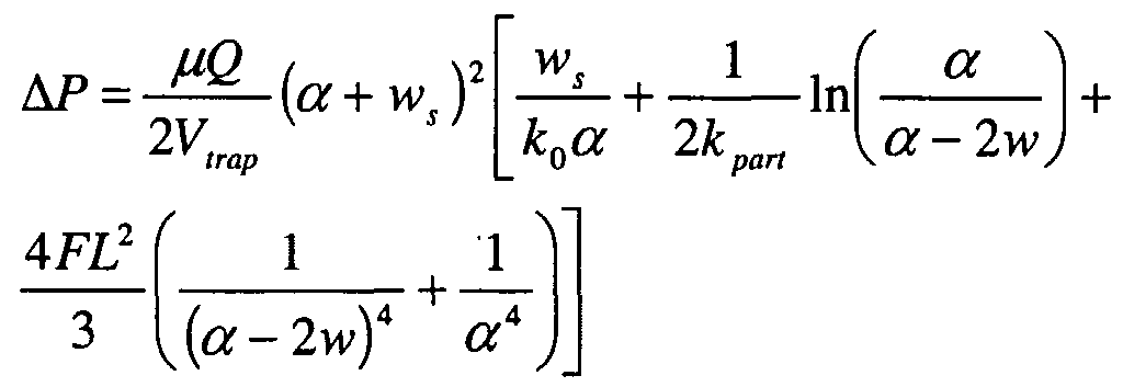
- the system can be calibrated using appropriate modelling techniques, for example modelling the filter temperature, and the exhaust pressure drop against particulate loading and exhaust volume flow rate providing a measure of increased fuel consumption to define the optimum DPF particulate loading at which to trigger regeneration.
- An appropriate pressure drop sub-model is characterised by the following equation:
- the invention can be applied to other particulate filters where the particulate bearing gas temperatures are insufficiently high to trigger self-sustaining regeneration or vary dependent upon system loadings. It will further be appreciated that any type of DPF and specific regeneration triggering loading value within the ranges discussed above can be adopted as desired.
Landscapes
- Engineering & Computer Science (AREA)
- Chemical & Material Sciences (AREA)
- Combustion & Propulsion (AREA)
- Mechanical Engineering (AREA)
- General Engineering & Computer Science (AREA)
- Analytical Chemistry (AREA)
- Chemical Kinetics & Catalysis (AREA)
- Processes For Solid Components From Exhaust (AREA)
Abstract
Description
Claims
Applications Claiming Priority (2)
| Application Number | Priority Date | Filing Date | Title |
|---|---|---|---|
| GBGB0114311.4A GB0114311D0 (en) | 2001-06-12 | 2001-06-12 | Improvements in particulate filters |
| GB0114311.4 | 2001-06-12 |
Publications (1)
| Publication Number | Publication Date |
|---|---|
| WO2002101208A1 true WO2002101208A1 (en) | 2002-12-19 |
Family
ID=9916430
Family Applications (1)
| Application Number | Title | Priority Date | Filing Date |
|---|---|---|---|
| PCT/GB2002/002625 Ceased WO2002101208A1 (en) | 2001-06-12 | 2002-06-12 | Improvements in particulate filters |
Country Status (2)
| Country | Link |
|---|---|
| GB (1) | GB0114311D0 (en) |
| WO (1) | WO2002101208A1 (en) |
Cited By (28)
| Publication number | Priority date | Publication date | Assignee | Title |
|---|---|---|---|---|
| FR2879671A1 (en) | 2004-12-17 | 2006-06-23 | Renault Sas | METHOD AND DEVICE FOR CONDITIONING THE REGENERATION OF A DIESEL ENGINE PARTICLE FILTER OF A MOTOR VEHICLE |
| US7155334B1 (en) | 2005-09-29 | 2006-12-26 | Honeywell International Inc. | Use of sensors in a state observer for a diesel engine |
| US7165399B2 (en) | 2004-12-29 | 2007-01-23 | Honeywell International Inc. | Method and system for using a measure of fueling rate in the air side control of an engine |
| US7182075B2 (en) | 2004-12-07 | 2007-02-27 | Honeywell International Inc. | EGR system |
| US7275374B2 (en) | 2004-12-29 | 2007-10-02 | Honeywell International Inc. | Coordinated multivariable control of fuel and air in engines |
| US7328577B2 (en) | 2004-12-29 | 2008-02-12 | Honeywell International Inc. | Multivariable control for an engine |
| US7357125B2 (en) | 2005-10-26 | 2008-04-15 | Honeywell International Inc. | Exhaust gas recirculation system |
| US7389773B2 (en) | 2005-08-18 | 2008-06-24 | Honeywell International Inc. | Emissions sensors for fuel control in engines |
| US7415389B2 (en) | 2005-12-29 | 2008-08-19 | Honeywell International Inc. | Calibration of engine control systems |
| US7467614B2 (en) | 2004-12-29 | 2008-12-23 | Honeywell International Inc. | Pedal position and/or pedal change rate for use in control of an engine |
| US7469177B2 (en) | 2005-06-17 | 2008-12-23 | Honeywell International Inc. | Distributed control architecture for powertrains |
| US7591135B2 (en) | 2004-12-29 | 2009-09-22 | Honeywell International Inc. | Method and system for using a measure of fueling rate in the air side control of an engine |
| US7810318B2 (en) | 2007-05-15 | 2010-10-12 | Gm Global Technology Operations, Inc. | Electrically heated particulate filter regeneration methods and systems for hybrid vehicles |
| US9170573B2 (en) | 2009-09-24 | 2015-10-27 | Honeywell International Inc. | Method and system for updating tuning parameters of a controller |
| US20160153330A1 (en) * | 2014-12-01 | 2016-06-02 | Hokuetsu Industries Co., Ltd., | Method of regenerating exhaust gas post-processing apparatus in engine-driven generator, and regeneration apparatus |
| US9650934B2 (en) | 2011-11-04 | 2017-05-16 | Honeywell spol.s.r.o. | Engine and aftertreatment optimization system |
| US9677493B2 (en) | 2011-09-19 | 2017-06-13 | Honeywell Spol, S.R.O. | Coordinated engine and emissions control system |
| US10036338B2 (en) | 2016-04-26 | 2018-07-31 | Honeywell International Inc. | Condition-based powertrain control system |
| US10124750B2 (en) | 2016-04-26 | 2018-11-13 | Honeywell International Inc. | Vehicle security module system |
| US10235479B2 (en) | 2015-05-06 | 2019-03-19 | Garrett Transportation I Inc. | Identification approach for internal combustion engine mean value models |
| US10272779B2 (en) | 2015-08-05 | 2019-04-30 | Garrett Transportation I Inc. | System and approach for dynamic vehicle speed optimization |
| US10309287B2 (en) | 2016-11-29 | 2019-06-04 | Garrett Transportation I Inc. | Inferential sensor |
| US10415492B2 (en) | 2016-01-29 | 2019-09-17 | Garrett Transportation I Inc. | Engine system with inferential sensor |
| US10423131B2 (en) | 2015-07-31 | 2019-09-24 | Garrett Transportation I Inc. | Quadratic program solver for MPC using variable ordering |
| US10503128B2 (en) | 2015-01-28 | 2019-12-10 | Garrett Transportation I Inc. | Approach and system for handling constraints for measured disturbances with uncertain preview |
| US10621291B2 (en) | 2015-02-16 | 2020-04-14 | Garrett Transportation I Inc. | Approach for aftertreatment system modeling and model identification |
| US11057213B2 (en) | 2017-10-13 | 2021-07-06 | Garrett Transportation I, Inc. | Authentication system for electronic control unit on a bus |
| US11156180B2 (en) | 2011-11-04 | 2021-10-26 | Garrett Transportation I, Inc. | Integrated optimization and control of an engine and aftertreatment system |
Citations (6)
| Publication number | Priority date | Publication date | Assignee | Title |
|---|---|---|---|---|
| US4549398A (en) * | 1981-06-22 | 1985-10-29 | Toyota Jidosha Kogyo Kabushiki Kaisha | Exhaust gas cleaning device for diesel engines |
| US4685290A (en) * | 1984-11-19 | 1987-08-11 | Nippon Soken, Inc. | Engine control with function to eliminate minute particles in exhaust gas |
| EP0411445A2 (en) * | 1989-08-02 | 1991-02-06 | Cummins Engine Company, Inc. | Regeneratable particulate filter trap system |
| US5195318A (en) * | 1989-12-28 | 1993-03-23 | Nissan Motor Co., Ltd. | Exhaust gas purifying device for an internal combustion engine |
| EP0603907A2 (en) * | 1992-12-23 | 1994-06-29 | Magnet-Motor Gesellschaft für magnetmotorische Technik mbH | Motor vehicle, particularly city-bus, with a dieselengine/generator unit |
| US5458673A (en) * | 1992-11-26 | 1995-10-17 | Nippon Soken, Inc. | Exhaust gas particulate purifying process for internal combustion engine |
-
2001
- 2001-06-12 GB GBGB0114311.4A patent/GB0114311D0/en not_active Ceased
-
2002
- 2002-06-12 WO PCT/GB2002/002625 patent/WO2002101208A1/en not_active Ceased
Patent Citations (6)
| Publication number | Priority date | Publication date | Assignee | Title |
|---|---|---|---|---|
| US4549398A (en) * | 1981-06-22 | 1985-10-29 | Toyota Jidosha Kogyo Kabushiki Kaisha | Exhaust gas cleaning device for diesel engines |
| US4685290A (en) * | 1984-11-19 | 1987-08-11 | Nippon Soken, Inc. | Engine control with function to eliminate minute particles in exhaust gas |
| EP0411445A2 (en) * | 1989-08-02 | 1991-02-06 | Cummins Engine Company, Inc. | Regeneratable particulate filter trap system |
| US5195318A (en) * | 1989-12-28 | 1993-03-23 | Nissan Motor Co., Ltd. | Exhaust gas purifying device for an internal combustion engine |
| US5458673A (en) * | 1992-11-26 | 1995-10-17 | Nippon Soken, Inc. | Exhaust gas particulate purifying process for internal combustion engine |
| EP0603907A2 (en) * | 1992-12-23 | 1994-06-29 | Magnet-Motor Gesellschaft für magnetmotorische Technik mbH | Motor vehicle, particularly city-bus, with a dieselengine/generator unit |
Cited By (37)
| Publication number | Priority date | Publication date | Assignee | Title |
|---|---|---|---|---|
| US7182075B2 (en) | 2004-12-07 | 2007-02-27 | Honeywell International Inc. | EGR system |
| FR2879671A1 (en) | 2004-12-17 | 2006-06-23 | Renault Sas | METHOD AND DEVICE FOR CONDITIONING THE REGENERATION OF A DIESEL ENGINE PARTICLE FILTER OF A MOTOR VEHICLE |
| USRE44452E1 (en) | 2004-12-29 | 2013-08-27 | Honeywell International Inc. | Pedal position and/or pedal change rate for use in control of an engine |
| US7165399B2 (en) | 2004-12-29 | 2007-01-23 | Honeywell International Inc. | Method and system for using a measure of fueling rate in the air side control of an engine |
| US7275374B2 (en) | 2004-12-29 | 2007-10-02 | Honeywell International Inc. | Coordinated multivariable control of fuel and air in engines |
| US7328577B2 (en) | 2004-12-29 | 2008-02-12 | Honeywell International Inc. | Multivariable control for an engine |
| US7467614B2 (en) | 2004-12-29 | 2008-12-23 | Honeywell International Inc. | Pedal position and/or pedal change rate for use in control of an engine |
| US7591135B2 (en) | 2004-12-29 | 2009-09-22 | Honeywell International Inc. | Method and system for using a measure of fueling rate in the air side control of an engine |
| US7469177B2 (en) | 2005-06-17 | 2008-12-23 | Honeywell International Inc. | Distributed control architecture for powertrains |
| US7389773B2 (en) | 2005-08-18 | 2008-06-24 | Honeywell International Inc. | Emissions sensors for fuel control in engines |
| US7155334B1 (en) | 2005-09-29 | 2006-12-26 | Honeywell International Inc. | Use of sensors in a state observer for a diesel engine |
| US7357125B2 (en) | 2005-10-26 | 2008-04-15 | Honeywell International Inc. | Exhaust gas recirculation system |
| US7415389B2 (en) | 2005-12-29 | 2008-08-19 | Honeywell International Inc. | Calibration of engine control systems |
| DE102008023397B4 (en) * | 2007-05-15 | 2011-04-07 | GM Global Technology Operations, Inc., Detroit | Methods and systems for regeneration of electrically heated particulate filters for hybrid vehicles |
| US7810318B2 (en) | 2007-05-15 | 2010-10-12 | Gm Global Technology Operations, Inc. | Electrically heated particulate filter regeneration methods and systems for hybrid vehicles |
| US9170573B2 (en) | 2009-09-24 | 2015-10-27 | Honeywell International Inc. | Method and system for updating tuning parameters of a controller |
| US9677493B2 (en) | 2011-09-19 | 2017-06-13 | Honeywell Spol, S.R.O. | Coordinated engine and emissions control system |
| US11619189B2 (en) | 2011-11-04 | 2023-04-04 | Garrett Transportation I Inc. | Integrated optimization and control of an engine and aftertreatment system |
| US9650934B2 (en) | 2011-11-04 | 2017-05-16 | Honeywell spol.s.r.o. | Engine and aftertreatment optimization system |
| US11156180B2 (en) | 2011-11-04 | 2021-10-26 | Garrett Transportation I, Inc. | Integrated optimization and control of an engine and aftertreatment system |
| US20160153330A1 (en) * | 2014-12-01 | 2016-06-02 | Hokuetsu Industries Co., Ltd., | Method of regenerating exhaust gas post-processing apparatus in engine-driven generator, and regeneration apparatus |
| US9695720B2 (en) * | 2014-12-01 | 2017-07-04 | Hokuetsu Industries Co., Ltd | Method of regenerating exhaust gas post-processing apparatus in engine-driven generator, and regeneration apparatus |
| US10503128B2 (en) | 2015-01-28 | 2019-12-10 | Garrett Transportation I Inc. | Approach and system for handling constraints for measured disturbances with uncertain preview |
| US11687688B2 (en) | 2015-02-16 | 2023-06-27 | Garrett Transportation I Inc. | Approach for aftertreatment system modeling and model identification |
| US10621291B2 (en) | 2015-02-16 | 2020-04-14 | Garrett Transportation I Inc. | Approach for aftertreatment system modeling and model identification |
| US10235479B2 (en) | 2015-05-06 | 2019-03-19 | Garrett Transportation I Inc. | Identification approach for internal combustion engine mean value models |
| US10423131B2 (en) | 2015-07-31 | 2019-09-24 | Garrett Transportation I Inc. | Quadratic program solver for MPC using variable ordering |
| US11144017B2 (en) | 2015-07-31 | 2021-10-12 | Garrett Transportation I, Inc. | Quadratic program solver for MPC using variable ordering |
| US11687047B2 (en) | 2015-07-31 | 2023-06-27 | Garrett Transportation I Inc. | Quadratic program solver for MPC using variable ordering |
| US10272779B2 (en) | 2015-08-05 | 2019-04-30 | Garrett Transportation I Inc. | System and approach for dynamic vehicle speed optimization |
| US11180024B2 (en) | 2015-08-05 | 2021-11-23 | Garrett Transportation I Inc. | System and approach for dynamic vehicle speed optimization |
| US10415492B2 (en) | 2016-01-29 | 2019-09-17 | Garrett Transportation I Inc. | Engine system with inferential sensor |
| US11506138B2 (en) | 2016-01-29 | 2022-11-22 | Garrett Transportation I Inc. | Engine system with inferential sensor |
| US10124750B2 (en) | 2016-04-26 | 2018-11-13 | Honeywell International Inc. | Vehicle security module system |
| US10036338B2 (en) | 2016-04-26 | 2018-07-31 | Honeywell International Inc. | Condition-based powertrain control system |
| US10309287B2 (en) | 2016-11-29 | 2019-06-04 | Garrett Transportation I Inc. | Inferential sensor |
| US11057213B2 (en) | 2017-10-13 | 2021-07-06 | Garrett Transportation I, Inc. | Authentication system for electronic control unit on a bus |
Also Published As
| Publication number | Publication date |
|---|---|
| GB0114311D0 (en) | 2001-08-01 |
Similar Documents
| Publication | Publication Date | Title |
|---|---|---|
| WO2002101208A1 (en) | Improvements in particulate filters | |
| EP1158143B1 (en) | Device for purifying the exhaust gas of a diesel engine | |
| US4549398A (en) | Exhaust gas cleaning device for diesel engines | |
| JP2894103B2 (en) | Exhaust gas purification device | |
| CN101363348B (en) | Electrically heated dpf start-up strategy | |
| JP2004011446A (en) | Fuel injection control device for internal combustion engine | |
| US20090000604A1 (en) | Engine system having aftertreatment and an intake air heater | |
| US8375705B2 (en) | Exhaust system implementing low-temperature regeneration strategy | |
| JP4446840B2 (en) | Accumulation device | |
| JP2001073743A (en) | Exhaust purifying device for diesel engine | |
| JP2003307117A (en) | Exhaust emission control device of internal combustion engine | |
| US20070028765A1 (en) | Hydrocarbon-enhanced particulate filter regeneration via microwave ignition | |
| CN100590301C (en) | Method and device for regeneration of exhaust gas filter | |
| JP4164634B2 (en) | Exhaust gas purification device for internal combustion engine | |
| CN101307712B (en) | Method and system for controlling particulate filter | |
| JP2003286820A (en) | Engine exhaust-emission control device | |
| KR20110087055A (en) | Back pressure sensitive exhaust line for vehicles equipped with particulate matter regeneration filter | |
| JPH10266826A (en) | Exhaust gas processing device for diesel engine | |
| JP2848204B2 (en) | Exhaust particulate cleaning equipment | |
| JP4554894B2 (en) | Exhaust gas purification method and exhaust gas purification system | |
| KR100841689B1 (en) | Control Method of Electric Heater Soot Filter for Reducing Particulate Matter in Diesel Hybrid Vehicles | |
| JPH0137138Y2 (en) | ||
| JP2003172125A (en) | Exhaust gas purification device | |
| JPH0710035Y2 (en) | White smoke reduction device for diesel engine | |
| JPH0511293Y2 (en) |
Legal Events
| Date | Code | Title | Description |
|---|---|---|---|
| AK | Designated states |
Kind code of ref document: A1 Designated state(s): AE AG AL AM AT AU AZ BA BB BG BR BY BZ CA CH CN CO CR CU CZ DE DK DM DZ EC EE ES FI GB GD GE GH GM HR HU ID IL IN IS JP KE KG KP KR KZ LC LK LR LS LT LU LV MA MD MG MK MN MW MX MZ NO NZ OM PH PL PT RO RU SD SE SG SI SK SL TJ TM TN TR TT TZ UA UG US UZ VN YU ZA ZM ZW |
|
| AL | Designated countries for regional patents |
Kind code of ref document: A1 Designated state(s): GH GM KE LS MW MZ SD SL SZ TZ UG ZM ZW AM AZ BY KG KZ MD RU TJ TM AT BE CH CY DE DK ES FI FR GB GR IE IT LU MC NL PT SE TR BF BJ CF CG CI CM GA GN GQ GW ML MR NE SN TD TG |
|
| 121 | Ep: the epo has been informed by wipo that ep was designated in this application | ||
| REG | Reference to national code |
Ref country code: DE Ref legal event code: 8642 |
|
| 122 | Ep: pct application non-entry in european phase | ||
| NENP | Non-entry into the national phase |
Ref country code: JP |
|
| WWW | Wipo information: withdrawn in national office |
Country of ref document: JP |