WO2001079943A1 - Controller, temperature regulator, and heat treatment apparatus - Google Patents
Controller, temperature regulator, and heat treatment apparatus Download PDFInfo
- Publication number
- WO2001079943A1 WO2001079943A1 PCT/JP2001/003180 JP0103180W WO0179943A1 WO 2001079943 A1 WO2001079943 A1 WO 2001079943A1 JP 0103180 W JP0103180 W JP 0103180W WO 0179943 A1 WO0179943 A1 WO 0179943A1
- Authority
- WO
- WIPO (PCT)
- Prior art keywords
- temperature
- control
- deviation
- representative
- operation signal
- Prior art date
- Legal status (The legal status is an assumption and is not a legal conclusion. Google has not performed a legal analysis and makes no representation as to the accuracy of the status listed.)
- Ceased
Links
Classifications
-
- G—PHYSICS
- G05—CONTROLLING; REGULATING
- G05B—CONTROL OR REGULATING SYSTEMS IN GENERAL; FUNCTIONAL ELEMENTS OF SUCH SYSTEMS; MONITORING OR TESTING ARRANGEMENTS FOR SUCH SYSTEMS OR ELEMENTS
- G05B13/00—Adaptive control systems, i.e. systems automatically adjusting themselves to have a performance which is optimum according to some preassigned criterion
- G05B13/02—Adaptive control systems, i.e. systems automatically adjusting themselves to have a performance which is optimum according to some preassigned criterion electric
- G05B13/0205—Adaptive control systems, i.e. systems automatically adjusting themselves to have a performance which is optimum according to some preassigned criterion electric not using a model or a simulator of the controlled system
- G05B13/024—Adaptive control systems, i.e. systems automatically adjusting themselves to have a performance which is optimum according to some preassigned criterion electric not using a model or a simulator of the controlled system in which a parameter or coefficient is automatically adjusted to optimise the performance
-
- G—PHYSICS
- G05—CONTROLLING; REGULATING
- G05B—CONTROL OR REGULATING SYSTEMS IN GENERAL; FUNCTIONAL ELEMENTS OF SUCH SYSTEMS; MONITORING OR TESTING ARRANGEMENTS FOR SUCH SYSTEMS OR ELEMENTS
- G05B11/00—Automatic controllers
- G05B11/01—Automatic controllers electric
- G05B11/32—Automatic controllers electric with inputs from more than one sensing element; with outputs to more than one correcting element
-
- G—PHYSICS
- G05—CONTROLLING; REGULATING
- G05B—CONTROL OR REGULATING SYSTEMS IN GENERAL; FUNCTIONAL ELEMENTS OF SUCH SYSTEMS; MONITORING OR TESTING ARRANGEMENTS FOR SUCH SYSTEMS OR ELEMENTS
- G05B11/00—Automatic controllers
- G05B11/01—Automatic controllers electric
- G05B11/36—Automatic controllers electric with provision for obtaining particular characteristics, e.g. proportional, integral, differential
- G05B11/42—Automatic controllers electric with provision for obtaining particular characteristics, e.g. proportional, integral, differential for obtaining a characteristic which is both proportional and time-dependent, e.g. P. I., P. I. D.
-
- G—PHYSICS
- G05—CONTROLLING; REGULATING
- G05D—SYSTEMS FOR CONTROLLING OR REGULATING NON-ELECTRIC VARIABLES
- G05D23/00—Control of temperature
- G05D23/19—Control of temperature characterised by the use of electric means
- G05D23/1919—Control of temperature characterised by the use of electric means characterised by the type of controller
-
- G—PHYSICS
- G05—CONTROLLING; REGULATING
- G05D—SYSTEMS FOR CONTROLLING OR REGULATING NON-ELECTRIC VARIABLES
- G05D23/00—Control of temperature
- G05D23/19—Control of temperature characterised by the use of electric means
- G05D23/1927—Control of temperature characterised by the use of electric means using a plurality of sensors
- G05D23/193—Control of temperature characterised by the use of electric means using a plurality of sensors sensing the temperaure in different places in thermal relationship with one or more spaces
- G05D23/1932—Control of temperature characterised by the use of electric means using a plurality of sensors sensing the temperaure in different places in thermal relationship with one or more spaces to control the temperature of a plurality of spaces
-
- G—PHYSICS
- G05—CONTROLLING; REGULATING
- G05D—SYSTEMS FOR CONTROLLING OR REGULATING NON-ELECTRIC VARIABLES
- G05D23/00—Control of temperature
- G05D23/19—Control of temperature characterised by the use of electric means
- G05D23/20—Control of temperature characterised by the use of electric means with sensing elements having variation of electric or magnetic properties with change of temperature
Definitions
- the present invention relates to a control device for controlling a physical state such as a temperature and a pressure of a controlled object, a temperature controller for controlling a temperature which is one of the physical states for the controlled object, and a heat controller using the temperature controller. It relates to a processing device. Background art
- Some temperature controllers are used for heat treatment in a semiconductor manufacturing process, for example, for controlling the temperature of a reaction tube of a thermal oxidation device.
- This thermal oxidation apparatus generates an oxide film while flowing necessary gas to a wafer placed in a reaction tube.
- the reaction tube is continuous, it is divided into a plurality of zones, and a heater and a temperature sensor are provided for each zone.
- the detection output of each temperature sensor is input to a temperature controller with a built-in microcomputer.
- the temperature controller controls each heater based on the detected output to perform temperature control for each zone.
- each zone of the reaction tube is thermally continuous. Therefore, the amount of heat generated by the heater in one zone affects the temperature sensors in other zones, causing so-called interference.
- interference can cause significant temperature variations, especially during transients and disturbances, making uniform temperature control difficult. Also, it is not easy to control each zone to a different target temperature due to such interference.
- an object of the present invention is to provide a control device capable of controlling a desired physical state by reducing the interference even if the control target has interference. Disclosure of the invention
- the control device of the present invention summarizes the deviation between detection information from a plurality of detection means for respectively detecting a physical state of a control target and a plurality of target information individually corresponding to the plurality of detection means.
- Converting means for converting the deviation of the information indicating the gradient of the physical state into the deviation of the information indicating the representative of the physical state; and the deviation of the information indicating the gradient or the deviation of the information indicating the representative from the converting means.
- a plurality of state control means each outputting an operation signal as a control deviation; and an operation signal from each of the state control means, for a plurality of operation means for operating the control target.
- Distribution means for allocating the control by each state control means so as to suppress the influence on the control by the other state control means.
- Physical state refers to the state of various physical quantities such as temperature, pressure, flow rate, velocity or liquid level.
- the gradient of a physical state refers to a gradient of various physical quantities such as a temperature gradient, a pressure gradient, a flow rate gradient, and a velocity gradient.
- the temperature gradient refers to a temperature difference, that is, a gradient temperature.
- the representative of the physical state refers to a representative representation of the physical state of the control target. For example, in the case of temperature, the average temperature of the control target, the temperature at a certain position (for example, the center position), and the like are used.
- the target information refers to information on a physical state control target, such as a target temperature, a target pressure, and a target flow rate.
- the operating means refers to a means for changing the physical state of the controlled object. For example, if it is a temperature, a heating means or a cooling means for increasing or decreasing the temperature of the controlled object.
- the detection information from the plurality of detection means is the deviation of the information indicating the gradient of the physical state and the deviation of the information indicating the representative.
- the physical state is temperature, it is a temperature gradient.
- Control is performed by converting the deviation of the gradient temperature (temperature difference) into the deviation of the average temperature indicating the representative temperature and the deviation of the temperature at a certain position.In other words, the control is performed by converting it into independent information without interference.
- the control by each state control means is distributed so as to suppress the influence on the control by the other state control means, so that it is possible to reduce the interference in the control of the control target having the interference. .
- control device of the present invention individually corresponds to the detection means based on each deviation between a plurality of pieces of detection information from a plurality of detection means for respectively detecting a physical state of a control target and a plurality of target information.
- a control device including a plurality of state control means for respectively outputting operation signals to a plurality of operation means based on a deviation corresponding to a certain detection means
- a control means different from the operation means corresponding to the certain detection means is provided.
- At least one non-interference control means for outputting an operation signal to the operation means is provided, whereby, similarly to the control device including the conversion means and the distribution means, control of a control object having interference In, the interference can be reduced.
- the decoupling control means controls the influence of the control by one state control means on the control by another state control means.
- the control device of the present invention estimates the physical state of the object to be processed based on detection information from a plurality of detecting means for respectively detecting the physical state of the processing means for processing the object, and Estimating means for outputting estimated information; converting means for converting a plurality of pieces of estimated information estimated by the estimating means into information indicating the gradient of the physical state and information indicating a representative of the physical state; A plurality of state control means for respectively outputting operation signals based on information indicating a gradient from the means or a report indicating a representative; operating signals from the respective state control means being operated by the processing means; Distribution means for allocating the plurality of operation means to be added so as to suppress the influence of the control by each state control means on the control by the other state control means.
- an object to be processed by the processing means for example, heat-treated by the heat-treating board, based on the physical state of the processing means, for example, detection information from a detecting means for detecting the temperature of the heat-treating board. Since the physical state of the wafer is estimated and control is performed based on the estimated physical state, interference can be reduced and the physical state of the object to be processed can be controlled to a desired state.
- control device of the present invention further includes a conversion unit that calculates a deviation between the plurality of pieces of estimation information estimated based on the detection information from the plurality of detection units and the plurality of pieces of target information, by using the conversion unit.
- the deviation may be converted into a deviation of information indicating the representative of the physical state, and each deviation may be individually given to a plurality of state control means.
- the present invention provides a conversion means for converting detection information from a plurality of detection means for respectively detecting a physical state of a control target into information indicating a gradient of the physical state and information indicating a representative of the physical state.
- a transfer coefficient (transfer function) for measuring a change and determining a distribution ratio by the distribution means is obtained in advance.
- control is performed by converting detection information from a plurality of detection means into information indicating a gradient of a physical state and information indicating a representative, that is, independent information without interference.
- control by each state control means is distributed by the distribution means so as to suppress the influence on the control by the other state control means, it is possible to reduce the interference in the control of the control target having the interference. It becomes possible.
- FIG. 1 is a schematic configuration diagram of a temperature control system according to a preferred embodiment of the present invention.
- FIG. 2 is a configuration diagram of a thermal oxidation apparatus used for explaining the system of the present invention.
- FIG. 3 is a block diagram of the temperature controller of FIG.
- FIG. 4 is a configuration diagram in a case where there are two temperature sensors, heaters, and PID control means.
- FIG. 5 is a diagram showing the configuration of the control target in FIG.
- FIG. 6 is a block diagram of the average temperature / gradient temperature calculating means (mode converter) 5 of FIG.
- FIG. 7 is a block diagram of the control system of FIG.
- FIG. 8 is a block diagram of the distribution means (pre-compensator) of FIG.
- FIG. 9 is a diagram for explaining the decoupling control technique.
- FIG. 10 is a diagram for explaining the predistorter according to the embodiment.
- FIG. 11 is a diagram showing a model of a control target.
- FIG. 12 is an equivalent circuit diagram of the control target.
- FIG. 13 is a configuration diagram of a conventional control system.
- FIG. 14 is a diagram showing a response waveform of the conventional example.
- FIG. 15 is a diagram showing a response waveform according to the embodiment.
- FIG. 16 is a diagram showing a target value response waveform according to the embodiment.
- FIG. 17 is a diagram showing a disturbance response waveform according to the embodiment.
- FIG. 18 is a diagram showing a target value response waveform of the conventional example.
- FIG. 19 is a diagram showing a conventional disturbance response waveform.
- FIG. 20 is a block diagram of the control system when there are three zones.
- FIG. 21 is a diagram for explaining a method of measuring the interference coefficient matrix P using the step response method.
- FIG. 22 is a schematic configuration diagram of the temperature control system corresponding to FIG.
- FIG. 23 is a diagram corresponding to FIG. 21 of another embodiment.
- FIG. 24 is a diagram for explaining a method of measuring the matrix P of interference coefficients using the limit cycle method.
- FIG. 25 is a block diagram of another embodiment.
- FIG. 26 is a block diagram of another embodiment.
- FIG. 27 is a block diagram of another embodiment.
- FIG. 28 is a block diagram of the PID control means of FIG.
- FIG. 29 is a characteristic diagram showing the relationship between temperature and heater resistance.
- FIG. 30 is a characteristic diagram showing the relationship between temperature and time constant.
- FIG. 31 is a block diagram of another embodiment.
- FIG. 32 is a diagram showing a heat treatment board.
- FIG. 33 is a configuration diagram for explaining the operation amount.
- FIG. 34 is a diagram showing a change in the operation amount when the tilt temperature control does not work.
- FIG. 35 is a diagram showing a change in the manipulated variable when the tilt temperature control operates.
- FIG. 36 is a block diagram of another embodiment.
- FIG. 37 is a block diagram of still another embodiment.
- FIG. 38 is a block diagram of another embodiment.
- FIG. 39 is a block diagram of another embodiment.
- FIG. 40 is a block diagram of another embodiment.
- FIG. 41 is a block diagram of another embodiment.
- FIG. 42 is a block diagram of another embodiment.
- FIG. 43 is a block diagram of another embodiment.
- FIG. 44 is a configuration diagram of the tilt temperature control.
- FIG. 45 is a block diagram corresponding to FIG.
- FIG. 46 is a block diagram of the embodiment.
- FIG. 47 is a block diagram of another embodiment.
- FIG. 48 is a block diagram of another embodiment.
- FIG. 49 is a block diagram of still another embodiment.
- FIG. 50 is a block diagram of another embodiment.
- FIG. 51 is a block diagram of a main part of another embodiment.
- FIG. 52 is a block diagram of a main part of another embodiment.
- FIG. 53 is a block diagram of another embodiment.
- FIG. 54 is a block diagram of the embodiment.
- FIG. 55 is a block diagram of another embodiment.
- FIG. 56 is a block diagram of another embodiment.
- FIG. 57 is a block diagram of another embodiment.
- FIG. 58 is a diagram showing the configuration of the processing point temperature estimator.
- FIG. 59 is a diagram for explaining the step response method.
- FIG. 60 is a diagram showing the configuration of the model.
- FIG. 61 is a diagram showing the configuration of a model from the heat treatment board to the wafer.
- FIG. 62 is a block diagram of the embodiment.
- FIG. 63 is a block diagram of another embodiment.
- FIG. 64 is a block diagram of another embodiment.
- FIG. 65 is a block diagram of still another embodiment.
- FIG. 66 is a block diagram of another embodiment.
- FIG. 67 is a block diagram of another embodiment.
- FIG. 68 is a block diagram of another embodiment.
- FIG. 69 is a block diagram of another embodiment.
- FIG. 70 is a block diagram of still another embodiment.
- FIG. 71 is a block diagram of another embodiment.
- FIG. 72 is a block diagram of another embodiment.
- FIG. 73 is a configuration diagram of temperature detection.
- FIG. 4 is a block diagram of another embodiment.
- FIG. 75 is a configuration diagram of the temperature detection.
- FIG. 76 is a block diagram of another embodiment.
- FIG. 77 is a configuration diagram of another embodiment. BEST MODE FOR CARRYING OUT THE INVENTION
- FIG. 1 is a schematic configuration diagram of a temperature control system using a temperature controller according to an embodiment of the present invention.
- the temperature control system according to the present embodiment includes a plurality of heaters 1 t to 1 n for heating the controlled object 3 and a plurality of heaters for individually detecting the temperature of the controlled object 3 corresponding to the plurality of heaters 1! To 1 n. Based on the temperature sensors S i ⁇ S n and the detection outputs of these temperature sensors 2 t to 2 n, each heater 1 to 1 n is operated via an electromagnetic switch (not shown) to control the temperature of the control target 3. And a temperature controller 4 according to the present invention.
- the control target 3 of this embodiment is one that thermally generates interference continuously, and the heaters 1 i to 1 n and the corresponding temperature sensors 2 t to 2 n are arranged close to each other. A plurality of zones are each formed.
- This temperature control system can be applied to, for example, the thermal oxidation device 18 shown in FIG. 2 described in the background art above, and the control target 3 is a reaction tube 19, arsenide - motor 1 i to 1 3, and the first to third heaters 2 1 i to 2 1 3 disposed to divide the periphery of the reaction tube 1 9, first to third temperature sensors 2 i the ⁇ 2 3, and the first to third temperature sensor 2 2 i to 2 2 3 for detecting a temperature of each zone, a temperature controller 4, be applied as a microcomputer 2 3 Tona Ru temperature controller You can do it.
- FIG. 3 is a block diagram of the temperature controller 4 of FIG.
- the temperature controller 4 includes an average temperature / gradient temperature calculating means (hereinafter also referred to as a “mode converter”) 5 as conversion means, PID control means 6 l to 6 n, and a distribution means (hereinafter referred to as “mode converter”). 7).
- the average temperature / inclined temperature calculating means 5 calculates an average temperature detected by the plurality of temperature sensors 2 t to 2 n and an inclined temperature (temperature difference) based on the detected temperatures as described later.
- the PID control means 6 i to 6 n are a plurality of temperature control means to which the average temperature calculated by the calculation means 5 or each of the gradient temperatures is input.
- the distribution means 7 distributes the operation signals (operation amounts) from the PID control means 6 i to 6 n to a plurality of heaters 1 n as a plurality of operation means at a predetermined distribution ratio as described later.
- the average temperature / gradient temperature calculation means 5, the PID control means 6 6n and the distribution means 7 are constituted by, for example, a microcomputer.
- temperature control is performed using the average temperature as the representative temperature calculated by the average temperature / inclination temperature calculation means 5 and a plurality of each of the inclination temperatures as control amounts.
- the average temperature / inclination temperature calculation means 5 as conversion means converts a plurality of detected temperatures, which are detection information from the plurality of temperature sensors 2 i to 2 n, into information of one average temperature and a plurality of inclination temperatures. Replace.
- the reason for performing the conversion is to make the information independent and easy to understand without interference. For example, the following calculation is performed.
- Mean temperature and gradient temperature calculating means 5 according to the following equation, the average temperature T a V, the first gradient temperature T t 1, the second gradient temperature T t 2, ... a n-1 of gradient temperature T t n - Calculate 1 .
- Ta v (S 1 + S 2 + ⁇ S n) ⁇ n
- T t 1 (S 1 + S 2 + —Shunt- ⁇ (n- 1) one S n
- T t 2 (S 1 + S 2+ S n-2) ⁇ ( ⁇ - 2)-S n-l
- S 1 detected temperature of the first temperature sensor 2i
- T a V average temperature of the detected temperatures of the temperature sensors 2 to 2 n
- T t 1 Average detection temperature of temperature sensors 2 i to 2 ni and temperature sensor 2 when temperature sensors 2 i to 2 n are divided into two, temperature sensor 2 t S n- i and temperature sensor 2 n n Detection temperature difference from temperature (gradient temperature),
- T t 2 multiple temperature sensors ⁇ . -i, temperature sensor 2 i S n-S and temperature sensor
- the temperature difference (inclined temperature) between the average detected temperature of the temperature sensors 2 i to 2 n - 2 and the detected temperature of the temperature sensor 2 when divided into two ni
- Ttn-1 Temperature difference (inclined temperature) between the detected temperatures of the temperature sensor 2i and the temperature sensor 22 The above formulas are summarized and expressed as follows using a matrix called a mode conversion matrix Gm. Can be.
- the average temperature T av and the plurality of gradient temperatures T t1 to T t are control amounts.
- the ramp temperature is not limited to this embodiment.
- there are various differences such as the temperature difference between the detected temperatures of adjacent temperature sensors, and the temperature difference between the average detected temperatures of each group when a plurality of temperature sensors are divided into two groups.
- the gradient temperature of is used.
- the temperature difference between the average detected temperatures of each group of multiple temperature sensors divided into two groups, the temperature difference of the average detected temperatures of each group further divided into two groups, and the The temperature may be calculated and used from a macro gradient temperature to a micro gradient temperature, such as a temperature difference between the average detected temperatures of the two groups.
- the temperature control may be performed separately from the information indicating the temperature gradient and the information indicating the representative temperature of the control target, for example, the average information.
- the PID control means 6i sets the average temperature to the target average temperature based on the control deviation between the average temperature from the average temperature / inclination temperature calculation means 5 and the target average temperature (target value of average temperature). And outputs an operation signal to the distribution means 7.
- the second PID control means 6 2 based on the control deviation between the first gradient temperature of the first target gradient temperature from the average temperature and gradient temperature calculating means 5 (a target value of the first gradient temperature), An operation signal is output to the distribution means 7 so that the first tilt temperature becomes the first target tilt temperature.
- An operation signal is output to the distribution means 7 based on the control deviation between the second inclination temperature and the second target inclination temperature (the target value of the second inclination temperature) so that the second inclination temperature becomes the second target inclination temperature. I do.
- the n-th PID control means 6 n calculates the (n ⁇ 1) -th slope temperature from the average temperature / slope temperature calculation means 5 and the (n ⁇ 1) -th target slope temperature (of the (n ⁇ 1) -th slope temperature). Based on the control deviation from the target value, an operation signal is output to the distribution means 7 so that the (n ⁇ 1) th ramp temperature becomes the (n ⁇ 1) th target ramp temperature.
- the first PID control means 6 controls the average temperature
- the second to n-th PID control means 62 to 6n respectively control the first to n-th gradient temperatures.
- the distribution unit 7 distributes an operation signal (operation amount) from each PID control unit 6 n to each of the heaters l 1 to ln. In the distribution, interference of the control of the average temperature or the gradient temperature by each of the PID control means 6 t to 6 n with the control of the average temperature or the gradient temperature by the other PID control means 6 i to 6 n respectively. Is performed so as to suppress.
- the above distribution is performed so that the inclination signal does not change by the operation signal.
- the operation is performed so that the average temperature and other inclination temperatures do not change by the operation signal.
- the control signals are distributed so that the control signals of the other PID control means are not affected by the operation signal of each PID control means.
- the distribution by the distribution means 7 will be described in more detail.
- FIG applied to the case of two channels with a second PID control means 6 2 for controlling the gradient temperature is the difference between the detected temperature of 2 2 This will be described with reference to FIG.
- FIG. 4 shows an example in which the present invention is applied to a control target 27 having two-input two-output interference.
- portions corresponding to FIG. 3 are denoted by the same reference numerals.
- 2 6 There 2 6 2, an adder for calculating a control deviation, in FIG. 3 illustrates included in the PID control means 6 have 6 2.
- the control target 27 has, for example, two inputs (HI, H2) and two outputs as shown in FIG. (PV 1, PV 2) is the control target with interference.
- the control target 27 is configured such that the first manipulated variable HI from the first PID control means 6 is supplied to the first adder 28, and is attenuated to 0.9 by the first attenuator 29 to perform the second addition.
- the second manipulated variable H 2 force from the second PID control means 62 is supplied to the second adder 30 while being attenuated to 0.9 by the second attenuator 31 to the first given to the adder 28, the addition output of the adder 28, 30, first, in the second delay element 32, 33 in a configuration provided respectively c this example, each operation amount HI, H2 0.9 Are added to the other at the rate of
- the average temperature-gradient temperature calculating means 5 the first feedback amount PV 1 from the second temperature sensor 2 2 2 detected temperature T 2 corresponding to the control object 27, the [rho V 2 and adder 8 as shown in FIG. 6, the attenuation to and outputs the average temperature Ta V to 1/2 attenuator 9, corresponding to the detected temperature 1, T 2 of both temperature sensors 2 2 2
- the subtractor 10 subtracts the feedback amounts PV1 and PV2 to output the slope temperature Tt.
- the control deviation between the average temperature T aV from the average temperature / inclination temperature calculation means 5 and the target average temperature is given to the first PID control means 6 via the adder 26.
- the first PID control means 6i outputs the operation signal '(operation amount) Ha V to the distribution means 7 based on the control deviation so that the average temperature becomes the target average temperature.
- the second PID control means 6 control deviation between the gradient temperature T t and the target gradient temperature from the average temperature and gradient temperature calculating means 5 is provided via the adder 26 2.
- the second PID control hand stage 6 based on the control deviation, the operation signal (operation amount) as gradient temperature becomes the target gradient temperature outputs an H t the allocation means 7.
- Allocation means 7 the operation signal (operation amount) of the PID controller 6 6 2 H a V, each heater 1 1 distribution ratio as follows H t; distributed to 1.
- FIG. 7 is a block diagram of a control system of the system of FIG.
- the operation amount Ha V given by the first PID control means 6 i for controlling the average temperature is controlled by the distribution means 7 to suppress interference, that is, a decoupling coefficient (a distribution ratio) which is a coefficient for decoupling. ) k 1; first in k 2, respectively as well as distributed to the second heater 1 1 2, an operation amount H t given from the second PID control means 6 2, non-interacting factor (distribution ratio) k 3 , 4 for the first and second heater 1! , 1 2 , respectively, so that the heat quantity H 2 is given to each of the nights 1 1 2 , respectively.
- the amount of heat Hi given to the first heater It is transmitted to the first temperature sensor 2 i by a transfer coefficient (interference coefficient), while the transfer coefficient (interference coefficient) is 1 2 to the second temperature sensor 2 2. It is transmitted to.
- First detection temperature T t and the average temperature T a V and gradient temperature T t is calculated each PID control from been detected temperature T 2 Metropolitan detected by the second temperature sensor 2 2 detected by the temperature sensor 2 i of control Le one-flop that is input to the means 61, 6 2 are formed.
- the average temperature T a V is shown as follows.
- the average temperature T av is a function of only the manipulated variable Ha v of the average temperature, and in order to suppress the influence of the manipulated variable H t of the gradient temperature, that is, in order to reduce interference, the term 111: Is set to 0.
- the slope temperature T t is a function of only the manipulated variable H t of the slope temperature, so as to suppress the influence of the manipulated variable H a V of the average temperature, that is, to achieve non-interference: Set the term of & to 0.
- k 2 — ⁇ (1 i-1 2 ) / (1 1 4 ) ⁇ kt
- the average temperature is controlled without affecting the gradient temperature
- the gradient temperature is controlled without affecting the average temperature, that is, non-interference that eliminates interference between the average temperature and the gradient temperature.
- the H t, non-interacting factor may be apportioned 1 ⁇ ⁇ ] ⁇ 4.
- second temperature sensor 2 To calculate the amount of heat of the first heater is first, second temperature sensor 2 have 2 2 transmitted transmission coefficient (interference coefficient), 1 2 and the second heat quantity of the heater 1 2 first It is necessary to know the transfer coefficient (interference coefficient) 1 1 4 transmitted to the second temperature sensor 2 2 2 .
- the decoupling coefficient (distribution ratio) ki k * can be dealt with by the gain of PID control if the ratio between k 2 and k 3 and k 3 and k 4 is known, so the absolute value is not necessarily required.
- the transfer coefficient (interference coefficient) lil * can be obtained as follows. That is, one heater is changed and the other heaters are fixed at a constant value.For example, the heater is kept on or off, and the ratio of the change amount of each temperature sensor to the change amount of the heater is defined as a transfer coefficient. You do it.
- the first and second temperature sensors 2 2 2 2 detected temperature
- k 2 — ⁇ (1 i- 1 2 ) / (1 s- 1 4 ) ⁇ ki
- the manipulated variable Ha V of the average temperature is 1 2 every heater 1! (Hj), allocated to 1 2 (H 2), the operation amount H t of tilt temperature, first heating evening to h (Eta ⁇ is intact, the second heater 1 2 (H 2), What is necessary is just to change a sign and to distribute.
- the distribution ratio (decoupling coefficient) can also be obtained as follows.
- Gc is as follows: Can be obtained as an inverse matrix.
- a matrix P of a transfer coefficient (interference coefficient), which is a characteristic of a controlled object at a certain time, is given by
- the distribution ratio (decoupling coefficient) is calculated using the transfer coefficient, but instead of the transfer coefficient, it is calculated using a transfer function that also represents frequency characteristics.
- the pre-compensation matrix G c which is the matrix of the distribution ratio (decoupling coefficient)
- the matrix P of the transfer coefficient (interference coefficient) is the inverse matrix of the product of the mode average matrix Gm and the matrix P of the transfer coefficient (interference coefficient), as described above. I explain in detail why we can ask.
- 6 i Sm denotes PID control means
- 7 denotes a pre-compensator
- 3 denotes a control target having interference
- 3 ′ denotes a control target after decoupling.
- decoupling Since you change any of the inputs to move only one output, it will fluctuate to the output you do not want to move. Therefore, it is only necessary to make one-to-one correspondence between closely related inputs and outputs so that when one input is changed, only the corresponding output changes. This is called decoupling.
- Gp (s) of the controlled object is a diagonal matrix
- the incoherence has already been established, but in general, Gp (s) is not a diagonal matrix.
- Gp (s) is not a diagonal matrix.
- G c (s) is determined so that Gp (s) G c (s) becomes a diagonal matrix, non-interference Can be achieved.
- the transfer function matrix Gc (s) of the precompensator 7 is obtained by the inverse matrix of the transfer function matrix Gp (s) of the controlled object 3 ′.
- the pre-compensator (distribution means) 7 in the present invention for controlling the gradient temperature will be described.
- the precompensator 7 in the present invention has two roles.
- the main role is to allocate the manipulated variables MV of the mean and slope temperature appropriately to each ch.
- a secondary role is the decoupling of known decoupling control.
- the manipulated variable MV which is the output of the PID, is also obtained by the average and the slope.
- MVl to MVm a means for distributing them before control target 3 is absolutely necessary.
- Compensator 7 was used. Decoupling is a secondary matter and does not mean that it is actively decoupling.
- the pre-compensator 7 may be determined by omitting the relationship of the control target 3 and approximating the control target without interference. This alone has a considerable effect.
- the pre-compensator Gc (s) of the known non-interference control is the inverse matrix of the control target Gp (s) .
- the transfer function matrix Gc (s) of the precompensator (distribution means) 7 is the transfer function matrix Gp (s) of the controlled object 3 and the transfer function matrix (the average temperature gradient temperature calculating means) 5 (Mode conversion matrix) It is obtained by the inverse matrix of the product of Gm (s).
- the operating signal (operating amount) Hav of the average temperature is attenuated to 1/2 by each of the attenuators 11 and 12, and added.
- the operating signal (operating amount) Ht of the gradient temperature is distributed to the adder 13 and the subtractor 14, respectively, and the output Hi of the adder 13 is supplied to the first heater. output of H 2 subtracter 14 is applied to the second heater 1 2.
- a case of changing the average temperature by the operation amount Ha V of the average temperature since the operation amount is distributed equally to each heat Isseki li, 1 2, influence the gradient temperature Without, that is, only the average temperature can be changed without interference. Also, in the case of changing the gradient temperature by the operation amount H t of tilt temperature is one of the heater, while the operation amount is given in 1x, to the other heater 1 2, given by -1 times Therefore, only the gradient temperature can be changed without changing the total amount of heat applied to both heaters, that is, without affecting the average temperature.
- FIG. 13 25 have 25 2 is a PID controller.
- the following controlled objects were modeled. That is, as the simplest example of the thermal interference system, two sets of heating evening 1 1 2 and the temperature sensor 2 2 2 As shown in FIG. 1 1, consider the heat treatment apparatus was connected with the thermal conductor 50 therebetween. The purpose of the control is to make the two temperatures uniform at an arbitrary set temperature.
- Figure 12 shows the electrical equivalent circuit of the control target. Ri, R 2, the thermal resistance from the temperature sensor to the ambient air, d, C 2 is the heat capacity in the vicinity of the temperature sensor.
- the input of the controlled object is the two heater heat amounts.
- a part of the heat amount of 1 t of the heater is transmitted through the heat conductor 50 and interferes with the temperature S 2 of the temperature sensor 2 2 with the heat resistance R 3 , and the heater 1 some of the second heat p 2 is likewise interfere with the temperature S of the temperature sensor 2 in the thermal resistance R 3.
- the thermal energy of the part of the heat p 2 is conducted to the machine body heat treatment apparatus in thermal resistance is fixed. However, the heat capacity of the machine was very large, so it was close to the ambient temperature.
- the disturbance was in the form of a 100 W step, and was applied under the same conditions as in the conventional example and this embodiment.
- FIG. 14 shows the response waveform of the conventional PID control using the parameters shown in Table 1 below
- FIG. 15 shows the response waveform of this embodiment using the parameters shown in Table 2 below.
- the PID parameter can be set independently for the slope temperature and the average temperature.
- the proportional gain Kp is made different from the proportional gain Kp was also set to a large value.
- FIGS. 16 to 19 show comparison results of the target value response and the disturbance response between the embodiment and the conventional example.
- the adjustment rule of CHR Choen, Hrones and Reswick
- no target value response overshoot was used for average temperature control
- disturbance response overshoot 20% was used for gradient temperature control.
- FIGS. 16 and 17 show the waveforms of the target value response and the disturbance response of this embodiment
- FIGS. 18 and 19 show the waveforms of the target value response and the disturbance response of the conventional example.
- the settling time was as long as 29 seconds and an overshoot was observed in the target value response of the conventional example in FIG. 18, the target value response in this embodiment was as shown in FIG. 16.
- the settling time was as short as 9 seconds, and no overshoot was observed.
- the settling time was as long as 32 seconds and overshoot was slightly recognized, whereas in the disturbance response of this embodiment, it is shown in FIG. Thus, the settling time was as short as 6 seconds, and no overshoot was observed.
- the average temperature control performed weak and slow control
- the gradient temperature control performed strong and fast control. Therefore, in both the target value response and the disturbance response, the overshoot was reduced. The settling time was short and satisfactory.
- the first to third temperature sensors S! Ss are respectively disposed in the first to third zones, the first zone and the second zone are adjacent to each other, and the second zone and the Zone 3 is adjacent, and for simplicity, it is assumed that there is interference only between adjacent zones.
- non-interference coefficients for eliminating interference for (distribution ratio) distribution first PID control means 6 for controlling the average temperature, the amount of operation Ha V to the second, third heater 1 2, 1 3
- the decoupling coefficient (distribution ratio) is 1 ⁇ , k 2
- the operation amount H tt of the second PID control means 62 for controlling the first gradient temperature T ti is the first and third heaters 1.
- the first gradient temperature T t 1, the second, third temperature sensor 2 2, 2 3 of the detected temperature on 2, the temperature detected by the average of T 3 and the first temperature sensor 2 i detection is a difference between the temperature, also the second gradient temperature T t 2, the difference between the detected temperature T 2 of the second temperature sensor 2 2 and the third detected temperature T 3 of the temperature sensor 2 3
- the second gradient temperature T t 2 the difference between the detected temperature T 2 of the second temperature sensor 2 2 and the third detected temperature T 3 of the temperature sensor 2 3
- the average temperature T a V is expressed as follows.
- the average temperature T av is a function of only the manipulated variable Ha v of the average temperature, so as to eliminate the influence of the manipulated variables H ti and H 1 2 of the gradient temperature, that is, to reduce interference.
- H t 1 and H t 2 are set to 0.
- the pre-compensation matrix Gc which is the matrix of the distribution ratio (decoupling coefficient)
- the mode conversion matrix Gm can also be obtained from the mode conversion matrix Gm and the matrix P of the transfer coefficient (interference coefficient), as described above. It can be obtained from the PID control means 6i as well as the relative decoupling coefficients such as the first heater li.
- the matrix P of the transfer coefficient (interference coefficient) which is the characteristic of the controlled
- the pre-compensation matrix G c which is an example of the distribution ratio (decoupling coefficient) is determined as the inverse matrix of the product of the mode conversion matrix Gm and the matrix P of the transfer coefficient (interference coefficient). Can be. Therefore, in order to obtain the pre-compensation matrix G c, it is necessary to know the matrix P of the transfer coefficient (coefficient of interference) as described above.
- FIG. 21 is a diagram showing changes in the manipulated variables MV and feedback amounts PV for explaining a method of measuring the matrix P of the transfer function (interference coefficient) using the step response method according to the embodiment of the present invention. It is.
- the temperature control system shown in FIG. Nth multiple heaters from 1 ⁇ 1 n and each heater 1.
- FIGS. 21 (a) to 21 (d) show a system including a temperature controller 4 according to the present invention for controlling the temperature of the control target 3 by operating ⁇ 1 n via an electromagnetic switch (not shown). ), Stepwise manipulated variables MVO, MVl and MVn are sequentially applied to the heaters lo to ln as shown in FIG. 21), and the temperature sensors 2 shown in FIGS.
- FIG. 22 in order to clarify the correspondence between the elements a 00 to ann of the matrix P of the transfer function (interference coefficient) shown below, FIG. Although only the reference numerals are shown differently, the configuration is the same as described above.
- 0th heater 1 For example, 0th heater 1.
- FIG. 21 (h) A n .
- the detected temperature PV n of the temperature sensor 2 n of the n shown in FIG. 21 () of the temperature rise value delta PV / L per unit time based on it is an a nn.
- tc is a fixed time until the change in the detection temperature PV stabilizes with respect to the change in the manipulated variable MV.
- the influence of the temperature detected by each temperature sensor is measured in order, and the matrix P of the interference coefficient (transfer function) is obtained.
- the measurement of the matrix P of the interference coefficient (transfer function) is automatically performed when the temperature control system is started, and the matrix P of the interference coefficient (transfer function) and a preset mode are set.
- the pre-compensation matrix Gc which is a row example of the distribution ratio (decoupling coefficient) is obtained from the transformation matrix Gm, and the manipulated variables are distributed based on the pre-compensation matrix Gc as described above. Slope temperature control without interference will be performed.
- each PID control means 6 constituting the temperature controller 4. Since ⁇ 6 n only outputs the step-shaped manipulated variables in order and does not perform PID control, the PID control means 6 simultaneously obtains the interference coefficient matrix P. The parameters of PID control of ⁇ 6 n can be obtained together.
- a step-like manipulated variable MV is given, so that the temperature rises. Therefore, as shown in FIGS. 23 (a) to (d) i, a pulse-shaped manipulated variable MV0 to MV having a certain width so that the interference coefficient can be measured at room temperature without such a rise in temperature. n may be given in order.
- Other configurations are the same as those in the embodiment of FIG.
- measurement may be performed simultaneously at places where the degree of interference is weak. For example, 0th heater 1. If the heater and the n-th heater 1 n are far apart and hardly interfere with each other, the 0th heater 1 MVn and MVn are given at the same time, and PVn for MV0 is set to 0 and PV0 for MVn is set to 0 at this time. By the way, the measurement time can be reduced by performing the measurement at the same time.
- FIG. 24 illustrates a method of measuring the matrix P of the interference coefficient (transfer function) using the limit cycle method according to another embodiment of the present invention. 22 corresponding to FIG. 21 described above.
- each heater 1 MV0 to MVn are sequentially varied to the plus side and the minus side, and the maximum amplitude APVZL of the detected temperature PV0 to P Vn at that time is divided by the unit time.
- Other configurations are the same as the above-described step response method.
- the manipulated variable MV is changed between the positive side and the negative side.
- the matrix P of the interference coefficient can be measured while maintaining the actual operating temperature. Therefore, the interference coefficient can be obtained with higher accuracy.
- the ID control means controls the average temperature to be the target average temperature (the target value of the average temperature) or the gradient temperature to be the target gradient temperature (the target value of the gradient temperature).
- the target average temperature and target slope temperature are set by the user, but it is difficult for users who previously set the target temperature for each channel to set the target average temperature and target slope temperature. is there.
- a mode converter 5 ′ for calculating the target average temperature and the target inclination temperature from the target temperature SP for each ch may be provided.
- portions corresponding to FIG. 4 described above are denoted by the same reference numerals.
- the mode converter 5 ′ has the same configuration as the mode converter 5 that calculates the average temperature and the inclination temperature from the detected temperature of the temperature sensor at each ch, which is the feedback amount from the control target 27.
- the mode converter 5 ′ By adding the mode converter 5 'in this way, the user can control the average temperature and the slope temperature.
- the target temperature SP can be set for each channel in the same way as before, without considering the degree.
- FIG. 26 As shown in FIG. 26, as shown in FIG. 26, the temperature between the detected temperature PV of each channel temperature sensor and the target temperature SP, which is the amount of feedback from the control target 27.
- a mode converter 5 ′′ may be provided as a conversion means for calculating the deviation and calculating the average temperature deviation and the inclination temperature deviation as the control deviation from the temperature deviation for each channel.
- the mode converter 5 ′ ′ has the same configuration as the mode converter 5 that calculates the average temperature and the gradient temperature from the temperature detected by each channel temperature sensor, which is the feedback amount from the control target 27.
- the user can set the target temperature of each channel in the same manner as in the related art without considering the average temperature and the gradient temperature, but can use only one mode converter 5 ′ ′′.
- the memory capacity can be reduced and the processing can be simplified.
- the mode converters 5 and 5 ′ convert the temperatures detected by the plurality of temperature sensors into the average temperature and the gradient temperature.
- the mode converter 5 '' converts the temperature deviation between the detected temperature from the plurality of temperature sensors and the target temperature into an average temperature deviation which is the deviation between the detected average temperature and the target average temperature, and This is converted into a gradient temperature deviation which is a deviation between the detected gradient temperature and the target gradient temperature.
- the detected temperature is converted into the average temperature and the gradient temperature, and then the control deviation is obtained.
- the temperature deviation between the detected temperature and the target temperature is obtained.
- the temperature deviation is converted into an average temperature deviation and a gradient temperature deviation, which are control deviations.
- FIG. 27 is a configuration diagram of still another embodiment of the present invention, and portions corresponding to the above-described embodiments are denoted by the same reference numerals.
- the control parameters of the respective PID control means ⁇ n are corrected according to the average temperature based on the detected temperatures of the plurality of temperature sensors, which is the amount of feedback PV from the control target 27. .
- FIG. 28 is a block diagram showing the inside of the PID control means 6i of FIG.
- the proportional gain Kp of the proportional element 80 is corrected by the correction means 81 based on the average temperature from the mode converter 5, and the change in the gain caused by the change in the resistance of the heater due to the temperature change.
- the integration time T i of the integration element 82 and the differentiation time T d of the differentiation element 83 are corrected by the correction means 84 to compensate for the change in the time constant due to the temperature change.
- R. I the reference temperature To, for example, the resistance at room temperature, and 7 7 is the temperature coefficient. Since the voltage V applied to the heater is constant, the current flowing through the heater changes according to the change in the resistance value of the heater. Even if the heater is driven with the same pulse width, the electric power ⁇ depends on the temperature. It will change like this.
- the gain G of the control loop changes as follows depending on the temperature.
- Po and Go are reference temperature T. Power and gain.
- a correction value of the proportional gain Kp is calculated according to the following linear approximation, and the proportional gain of the proportional element 80 is calculated.
- the correction is performed by the correction means 81.
- PVo is the reference temperature such as room temperature, Kp. Is a proportional gain at the reference temperature.
- the time constant changes with temperature as shown by the solid line in FIG. 30.
- the solid line A for example, the following approximation shown by the broken line B A linear equation can be considered.
- the integral time T i and the differential time Td of the PID parameter corresponding to the time constant can also be linearly approximated as follows.
- T i ⁇ 77 i (P V-P Vo) + 1 ⁇ T i o
- Td ⁇ r? D (P V-P Vo) + 1 ⁇ Tdo
- Td are integration time and derivative time at the reference temperature To, and n i and TTd are temperature coefficients.
- the temperature coefficients 77 1 and 77 d can be calculated, for example, by previously measuring the dead time by the step response method.
- the correction values of the integration time T i and the differentiation time Td are calculated according to the first-order approximation formula, and the integration time T i and the differentiation time Td of the integration element 82 and the differentiation element 83 are corrected.
- PID control is performed by correcting the proportional gain Kp, the integration time T i and the differentiation time Td according to the average temperature based on the detected temperature, so that the change in gain due to temperature is compensated and the temperature as a time constant Therefore, the hunting and overshoot can be suppressed without changing the PID parameter according to the temperature to be controlled as in the conventional example.
- the proportional gain Kp, the integration time T i, and the differentiation time Td are corrected using the average temperature based on the detected temperature.
- the correction using the target average temperature is performed. May be.
- the processing load by using a fixed value of the target average temperature is lower than when the average temperature that changes every moment is used. Can be greatly reduced.
- the proportional gain Kp, the integration time T i, and the differentiation time Td Although all corrections have been made, as another embodiment of the present invention, at least one of the proportional gain Kp, the integration time T i, and the differentiation time Td may be corrected.
- the three parameters (ka, kb, kc) are obtained as follows.
- the temperature value at three points (T i, T 2 , ⁇ 3 ).
- Te no te. ka (T i-To) 2 + kb (T i-To) + kc
- T 2 / r 0 ka (T2-T0) 2 + kb (T2-T0) + kc
- the three variables are mathematically determined, so the three parameters (ka, kb, kc) can be determined.
- the time constant changes with respect to the temperature of the n + 1 point. It can be obtained from data.
- FIG. 31 is a block diagram of a temperature controller according to another embodiment of the present invention, and portions corresponding to the embodiment of FIG. 3 described above are denoted by the same reference numerals.
- an adder 26 26 n for outputting a control deviation between the inclination temperature PVg l ⁇ PVg (n- 1) are shown outside of the PID control means 6! ⁇ 6 ".
- a limiter 40 is provided as limiting means for limiting the operation amount (operation signal) from the PID control means 6 for average temperature control.
- the heat-treating board 61 has a wafer 60 placed thereon and heat-treated.
- the heat-treating board 61 is concentrically divided into an outer circle 62, an intermediate part 63, and a center part 64. Individually corresponding heaters 65 to 67 are provided to control the temperature of each zone.
- Signal signal outputted from the average for the PID controller 6 t is the average output MV
- the tilt PID controller 6 2 is inclined MV.
- the average MV and the slope MV pass through the pre-compensator (distribution means) 7 and further pass through the saturation limiter 41 412 to become the MV for each ch of ch 1 MV and ch 2 MV.
- Each MV is limited because it cannot output 0% or less and 100% or more for each channel.
- PID control means 6 t ⁇ 6 n - operation amount from i is In the event of a large disturbance that saturates, the slope temperature control will appear in the table without hiding in the saturation of the manipulated variable for each channel, enabling uniform operation.
- FIG. 36 is a block diagram of another embodiment of the present invention, and portions corresponding to the above-described embodiment are denoted by the same reference numerals.
- the average rather than the amount of operation of the temperature control, is provided with a limiter 4 2 2 ⁇ 4 2 n for limiting the operation amount of the gradient temperature control.
- limiters 40, 42 2 to 42 n that limit the operation amounts of both the average temperature control and the tilt temperature control are provided. May be provided.
- the upper limit of the operation amount is limited by the limiter.
- the lower limit or both may be limited.
- the limit value of the limiter may be variably adjusted.
- FIG. 38 is a block diagram of a temperature controller according to another embodiment of the present invention, and portions corresponding to the embodiment of FIG. 4 described above are denoted by the same reference numerals.
- a fine tuning device 43 is provided for finely adjusting the balance between the average temperature control and the gradient temperature control.
- the user sets a control balance coefficient in the fine tuning device 43 by, for example, communication. by, in the fine-tuning unit 4 3, and outputs the average temperature control correction value and the gradient temperature control correction value corresponding to the control balance coefficient, changing the parameters Isseki of each PID control means 6 6 2 in that the correction value Is what you do.
- the parameter to be changed is, for example, a PID control parameter or a limit value for limiting the operation amount, which will be described later.
- control of the ramp temperature is strong and fast
- control of the average temperature is weak and slow
- control of the ramp temperature is weak and slow
- control of the average temperature is strong and fast. Since the optimum condition varies depending on the application and the characteristics of the controlled object, the user changes the control balance coefficient according to the change, and the Fine-tuning of the control conditions (fine tuning) that suits the situation is performed.
- An example of making a strong adjustment is to increase the proportional gain ⁇ increasing the limit value, while an example of making a weak adjustment is to reduce the proportional gain or reduce the limit value.
- an example in which the integration time constant and the differentiation time constant are shortened is to increase the integration time constant and an example in which the integration time constant and the differentiation time constant are increased.
- the user sets the control balance coefficient according to the application and the characteristics of the control object, and the PID control parameters and the like corresponding to the control balance coefficient are calculated by the fine-tuning unit 43 and corresponded. in which control parameters such as PID control means 6 have 6 2 is changed. Therefore, the arithmetic processing by the fine tuning device 43 is defined according to the parameter to be changed, the control balance coefficient, and the like.
- the control balance coefficient is the same as the average temperature control correction value, and the fine tuning device 4 is used in accordance with the average temperature control correction value.
- the inclination temperature control correction value is determined.
- the parameters of the gradient temperature control are changed based on the parameters of the average temperature control.
- the average temperature control parameter may be changed based on the gradient temperature control parameter.
- the slope temperature control and the average temperature control may be in a trade-off condition as described later. For example, if one parameter of the gradient temperature control is strengthened, it is best to decrease the parameter of the average temperature control at a minimum, and to improve the characteristics of the gradient temperature control, the average temperature control is improved. The operation is to weaken the parameter of.
- the average manipulated variable and the tilt manipulated variable are added after multiplying the coefficient by the precompensator, and It becomes an operation amount and is transmitted to the control target.
- the manipulated variable is then limited by a limit of 0% to 100%. In some cases, it is set smaller than this range.
- One way to adjust the trade-off is to balance the PID parameters. For example, if the proportional gain of the slope is larger than the average proportional gain, the manipulated variable of the slope is larger than the average manipulated variable. Therefore, when the slope and the average manipulated variable are added and saturated in the pre-compensator, the control is performed with the slope priority.
- FIG. 40 is a block diagram of a temperature controller showing an example of a more specific embodiment of the present invention, and is basically the same as FIG. 31 described above.
- control parameters of the PID are adjusted according to the control balance coefficient.
- the PID control means 6 of the average temperature control is controlled by the control balance coefficient.
- the upper limit value of the limiter 45 that limits the operation amount of t is changed.
- FIG. 41 is a block diagram of another embodiment of the present invention, and portions corresponding to the above-described embodiment are denoted by the same reference numerals.
- the fine tuning unit 46 calculates the upper limit value of the operation amount of the average temperature control. This is effective when the temperature is high and you want to raise the upper limit. In other words, the higher the temperature, the greater the amount of heat removed by the heat treatment. For example, when a wafer is placed on a high-temperature heat treatment board, the amount of heat taken by the wafer increases. In other words, the disturbance increases, and the average temperature tends to saturate. If the manipulated value of average temperature control is small due to saturation, it takes time to return the average temperature. To prevent this, at high temperatures, it may be desirable to increase the upper limit of the manipulated variable for average temperature control, which is effective in such cases. In other words, in the fine tuning unit 46, based on the control balance coefficient, the average temperature, and the average temperature (PV average) from the gradient temperature control means (mode converter) 5, if the temperature rises, the upper limit of the limiter 47 It works to increase.
- control balance coefficient + limit value is set as a new limit value.
- the limit value is set to 100% at room temperature, and the control balance coefficient is The positive side gives priority to responsiveness (average control priority), and the minus side gives uniformity priority (gradient control priority).
- the upper limit value of at least one limiter 48 for limiting the operation amount of the inclination temperature control by the control balance coefficient is limited.
- the temperature control may be limited and the average temperature control may be prioritized.
- the limit values of both the limiter of the average temperature control and the limiter of the inclination temperature control may be changed, and furthermore, the control parameter of PID may be changed together.
- control balance coefficient may be automatically switched.
- control balance coefficient may be switched in accordance with the mounting of the jewel on the heat treatment board. .
- the present invention is not limited to the control for making the gradient temperature equal to 0, but may be applied to a control in which the gradient temperature has a temperature gradient having a certain value.
- FIG. 43 is a configuration diagram of a temperature control system including a temperature controller according to another embodiment of the present invention.
- the temperature controller of this embodiment is different from the temperature controller of FIG. It has the same function and performs non-collision control based on the average temperature and the gradient temperature. That is, the temperature controller of this embodiment is obtained by adding the mode converter 5 ′ ′, the first and second PID control means 66 2 and the precompensator (distribution means) 7 in FIG. vessel 7 0 2 and is constituted by first to replace the first 4 PID control means 6 '- 6 4' It is what is done.
- the processing in the mode converter 5 ′′, the first and second PID control means 66 2 and the pre-compensator (distribution means) 7 in FIG. 26 is performed by the mode converter 5 ′′ and the corresponding mode conversion matrix G m.
- the matrix G PID corresponding to the second PID control means 6 6 2 and a pre-compensation matrix G c corresponding to the predistorter 7, represented by G c XG PID XGM, which and you can replace the the adder 70 70 2 and the first to fourth PID controller 6-6 4 'shown in FIG. 43 is expressed as follows.
- FIG. 44 is a block diagram of the gradient temperature control corresponding to FIG. 26.
- the temperature controller 4 includes a mode converter 5, PID controllers 6 to 6m, and a precompensator 7.
- this temperature controller G tc is represented by an equation using a pre-compensator Gc ;, a PID controller Gp id and a mode converter Gm, the following is obtained.
- G tc G c G pid Gm
- Gp ⁇ d has a frequency characteristic in which the gain changes with respect to the frequency by differentiation and integration, but Gc and Gm are coefficients having no frequency characteristic.
- G tc! G c!! G pid x Gm 1 1 + G c 1 2 G pid 2 Gm 21
- G tc 22 G c 21 Gp id x Giri! 2 + G c 22 Gp id 2 Gm 22
- k l to k 4 are constants irrelevant to the frequency, and are the following values.
- the PID controller Gp id (s) can express the frequency characteristics (hereinafter called the transfer function) using s of the Laplace transform as follows.
- Gp i d (s) Kp (1 + 1 / (T i s) + Td s)
- Kp, T i, and Td are proportional gain, integration time, and derivative time.
- equations that use imperfect differentiation or differential leading equations are used, but for simplicity, the simplest equations with these omitted are described.
- T in! Kp n! ! (T i X T i 2 ) / (kl Kp 1 T i 2 + k 2Kp 2 T i 1 )
- T dn! (Kl KP iTd i + k 2Kp 2 Td 2 ) / Kp n xl
- the PID parameter in the temperature controller of FIG. 45 can be obtained by this equation.
- the PID parameter of the gradient temperature control in FIG. 26 can be converted into the PID of the gradient temperature control in FIG. 43 by the above equation.
- the sum of four PID controllers multiplied by a certain ratio is shown to be a PID controller.
- To find the PID parameters at that time Is also shown.
- Gc and Gm are shown in the example where the frequency characteristics are constant.
- Gc and Gm of transfer functions with non-constant frequency characteristics can be realized by the same formula.
- the s called a PID controller is not a secondary controller but a tertiary or higher one, which makes it possible to achieve more sophisticated but sophisticated control.
- the entire PID controller Gtc (s) in FIG. 43 is as follows.
- G tc! (S) Kp n ! (1 + 1 / (T in 1 X s) + Td nns)
- G tc! 2 (s) K pn J a (1 + 1 / (T in 12 s) + T dn! 2 s)
- G tc 21 ( s) K pn 2! (1 + 1 / (T in 21 s) + T dn 21 s)
- G tcaa (s) K pn 22 (1 + 1 / (T in 22 s) + T dn 22 s)
- the above consists of four PID controllers.
- Kpn 11 k lKp 1 Hk 2 Kp 2
- T dn! (K 1 Kp X T d! + 1 ⁇ 2 ⁇ 2 ⁇ (1 2 ) / K pn!!
- Kpn 12 k 3KP! + K4 Kp 2
- T in! 2 K pn! 2 (T i; .T i 2 ) / (k 3 K p JT i 2 + k 4 K p T i:)
- Td n 12 (! K 3Kp iTd + 3 ⁇ 4: 4 ⁇ 2 ⁇ 2) / Kp n 12
- T ina! K pn 2 ! (T i: T i 2 ) / (k 5 K p! T i 2 -I-k 6 K p T i!)
- T dn 2 ! (K 5 K p X T d! + K 6 Kp 2 Td 2 ) / K pn 2!
- T dn 22 (k 7Kp 1 Td 1 + k 8Kp 2 Td 2 ) / K pn 22
- the temperature controller of the present invention shown in FIG. 46 the operator on the basis of the matrix expression described above, setting it to calculate the PID parameters of the first to fourth PID controller 6-6 4 ' do it.
- the mode converter 5 ′′ and the pre-compensator 7 are not required.
- first, fourth PID control means 6, 6 4 ' first, based on the temperature deviation corresponding to the detected temperature PV1, PV2 from the second temperature sensor, the corresponding first, whereas a conventional manner PID control means corresponding to each channel to output the operation signal to the second heater evening, the second PID controller 6 2 ', a second temperature sensor
- the third PID control means 6 3 ′ outputs an operation signal to the first heater based on the temperature deviation corresponding to the detected temperature PV 2 from the first temperature sensor.
- c Based on the temperature deviation corresponding to PV 1, c outputs an operational signal to the second heater that is, the second PID controller 6 2 ', the control according to the fourth PID control means 6, the
- the third PID control means 6 3 ′ operates so as to eliminate or reduce the influence on the control of the first PID control means 6, and the control by the first PID control means 6 It operates to eliminate or reduce the effect on the control of 4 'and operates as a decoupling control means.
- the present invention is not limited to a multipoint temperature controller having a plurality of inputs and outputs as shown in FIG. 46, and may be configured by combining a plurality of single-point temperature control temperature controllers.
- Figure 47 shows an example of combining four of the temperature controller 7 11-7 1 4 such single point control, its function is the same as the temperature regulator of FIG. 46.
- FIG. 48 is a configuration diagram of another embodiment of the present invention, and portions corresponding to FIG. 46 are denoted by the same reference numerals.
- the operator, proportional gain k P is a first, second PID control means 6 6 2 of PID parameters Isseki mode conversion matrix Gm, precompensation matrix Gc and 26, the integration time constant T i, by setting the derivative time constant TD, the calculation means 72 is intended to automatically first. 1 to PID parameter of the fourth PID control means 6i ' ⁇ 6 4' is set are computed, There is no need for the operator to perform complicated calculations or set PID parameters.
- PID control means 6 to 6 4 ′ are provided for two-channel temperature control, but at least one PID control means is provided. In any case, some effects can be achieved.
- the present invention can be similarly configured for three or more channels.
- the present invention can be configured with '1-6 9'.
- the second PID controller 6 2 ' the control of the second channel that corresponds to the second temperature sensor is provided to control the first channel corresponding to the first temperature sensor
- the third PID control means 6 3 ′ operates to eliminate or reduce the influence of the control of the third channel corresponding to the third temperature sensor on the first channel.
- the fourth PID control means 6 4 ' control of the first channel, and sea urchin operation by or to reduce eliminate the influence on the control of the second channel
- the The sixth PID control means 6 6 ′ operates to eliminate or reduce the influence of the control of the third channel on the control of the second channel
- the seventh PID control means 6 Control of the first channel gives control of the third channel Operative to be or smaller rather than a sound
- PID control means 6 8 of the 8 ' control of the second channel, but operates to eliminate the effect or reduced to give the control of the third channel Things.
- FIG. 51 is a block diagram of a main part of another embodiment of the present invention. For example, if the detection signal line from the temperature sensor that detects the temperature of the heat treatment equipment breaks during the heat treatment of the wafer in the heat treatment equipment, it is immediately detected and the effect can be affected. It is hoped that control can be performed as much as possible, thereby suppressing the occurrence of defective products.
- a mode converter 5a with sensor disconnection compensation for detecting disconnection of the temperature sensor and compensating for the disconnection is provided. Detects disconnection of detection signal lines from three temperature sensors in addition to detector 5 Disconnection means 73 and replacement means 74 for replacing the detection output of the temperature sensor in which the disconnection is detected with the average temperature detected by the temperature sensor.
- the configuration for detecting the disconnection of the detection signal line from the temperature sensor and compensating for the disconnection may not be provided in the mode converter 5 as the mode converter 5a with sensor disconnection compensation as in this embodiment. Of course, it is of course possible to provide it separately outside the mode converter 5.
- the disconnection detecting means 73 compares the average temperature from the mode converter 5 with the detected temperatures PV 1 to PV 3 from the first to third temperature sensors, respectively. beyond was sometimes, eh Bei first to third comparator 7 5 i to 7 5 3 that outputs an average temperature of a disconnection, substituted means 7 4, the output of each comparator 7 5 t ⁇ 7 5 3 It has the output of the temperature sensor, the ratio ⁇ 7 5 i to 7 5 3 first to third outputs switch to the average temperature of the switching device 7 6 i to 7-6 3 responds to.
- the 5 1 the detection signal line from the second temperature sensor is disconnected, the average temperature which is detected by the second comparator 7 5 2 is output to the second switch 7 6 2, second switches e unit 7 6 2, in which the average temperature calculated in the mode converter 5 instead of the output PV 2 of the second temperature sensor, and outputs a mode converter 5 as a substituent temperature PV x is there.
- Mode converter 5 is responsive to an output of the first to third comparator 7 5 t ⁇ 7 5 3, without using the substituted average temperature corresponding to the temperature sensor disconnection is detected, broken
- the average temperature may be calculated only from the detected temperature from the temperature sensor that is not used, or may be calculated using the replaced average temperature.
- the slope temperature is calculated using the replaced average temperature.
- FIG. 52 is a diagram corresponding to FIG. 51 of another embodiment of the present invention, showing a case where the number of inputs and outputs is n, and corresponding portions are denoted by the same reference numerals.
- the output of the temperature sensor in which the disconnection is detected is replaced with the average temperature given via the comparator ys TS s
- the replacement means 74 is A plurality of proximity point average calculation circuits 77 i to 77 n are provided to calculate the average of the detected temperatures from a plurality of temperature sensors arranged in the vicinity of each temperature sensor.
- the average temperature of the detected temperatures of a plurality of proximity points calculated by the proximity point average calculation circuit 711-77n corresponding to the disconnected temperature sensor is output.
- the plurality of temperature sensors arranged in the proximity position include, for example, two temperature sensors arranged on both sides (on both sides) of a certain temperature sensor.
- the temperature of the control target can be changed to a desired state. It can be controlled to a close state.
- FIG. 53 is a configuration diagram of a control system according to still another embodiment of the present invention, and 5a corresponds to the mode converter 5a with sensor disconnection compensation of FIG. 51 or FIG. 52 described above.
- FIG. 54 is a diagram corresponding to FIG. 53 of another embodiment of the present invention, and corresponding portions are denoted by the same reference characters.
- each PID control means 6 i to have provided an operation signal switch 7 9 for switching the operation signal from the 6 3, an operation signal to the heater that corresponds to the temperature sensor disconnection is detected by the operation signal switch 7 9 The operation signal is switched to an operation signal for a heater adjacent to the heater.
- FIG. 55 is a configuration diagram of a mode converter 5 a with sensor disconnection compensation according to still another embodiment of the present invention.
- the mode converter 5 has first to third temperature.
- Sensor detection temperature 1 ⁇ ? ⁇ 3 the first slope temperature based on the average temperature, the detected temperature PVI of the first temperature sensor and the detected temperature PV2 of the second temperature sensor, and the detected temperature PV2 and the second temperature of the second temperature sensor.
- the temperature is converted into a second gradient temperature based on the detected temperature PV 3 of the temperature sensor 3.
- the slope temperature will change greatly. Is used to detect disconnection.
- Disconnection detecting means 7 3 of this embodiment first, the first respectively comparisons and second gradient temperature and the threshold, the second comparator 9 0 1; and 9 0 2, the comparators 9 O t, 9 0 and a 2 first to third output is provided for the gate circuit 9 lt S 1 3, the first temperature sensor is disconnected, the first gradient temperature greatly changes to the threshold
- the second comparator 9 outputs a O 9 0 2 and becomes a high level both of the second gate circuit 9 1 2 gives the detection output
- the third gate one bets circuit 9 1 3 detected by the second output of the comparator 9 0 2 exceeds the threshold value the second gradient temperature changes greatly at a high level Give output It's that.
- Replacement means 7 4 replacing detection output of the temperature sensor disconnected, provided with a respective gate circuit 9 1 L ⁇ 9 1 3 detection output of the first to third given respective switch 9 2 1 9 2 3 Therefore, the detection output of the temperature sensor adjacent to the disconnected temperature sensor is configured to be the replacement output PVx, and the first switch 92 is connected to the detection temperature PV3 of the third temperature sensor. the second, third switch 9 2 2 9 2 3, the detected temperature PV 1 of the first temperature sensor, and is configured to replace the detection output of the temperature sensor disconnected.
- FIG. 56 is a block diagram of a temperature controller 4 according to another embodiment of the present invention, and corresponds to FIG. 3 described above.
- a temperature controller In a conventional temperature controller, the temperature of a processing means such as a heat treatment board as a control target is controlled to a desired temperature, but the temperature of an object to be processed such as a wafer processed by the processing means is controlled to a desired temperature. Controlling was not considered, and merely controlled the temperature of the processing object indirectly by controlling the temperature of the processing means.
- the difference in the degree of contact with the object to be treated due to unevenness of the surface of the heat treatment board or the unevenness of the material of the heat treatment board causes The heat is not transmitted uniformly, so even if the temperature of the heat treatment board is controlled uniformly, the temperature of the processing object such as a wafer is not controlled uniformly, and a uniform heat treatment is not performed on the processing object.
- the temperature of the heat treatment board is controlled uniformly, the temperature of the processing object such as a wafer is not controlled uniformly, and a uniform heat treatment is not performed on the processing object.
- the conventional temperature controller can control the temperature of a processing means such as a heat treatment board, but controls the temperature of an object to be processed such as a wafer processed by the processing means to a desired state. I have no control.
- the temperature controller 4 performs a plurality of processes on the object to be processed by the processing unit based on the detected temperatures of the plurality of temperature sensors 2 i to 2 n that respectively detect the temperatures of the processing unit.
- the processing point temperature estimating means 100 calculates the temperature of each processing point of the processing object individually corresponding to each detection point of the processing means by each of the temperature sensors 2 i to 2 n, which will be described later. It is estimated in this way.
- the processing point temperature estimating means 100, the average temperature / gradient temperature calculating means 5, the PID control means 6 6n and the distribution means 7 are constituted by, for example, a microcomputer.
- a processing means such as a heat treatment board is operated and controlled, while an object to be processed such as a wafer processed by the processing means is controlled to a desired temperature state.
- a point temperature estimating means 100 is provided.
- FIG. 57 is a configuration diagram of a temperature control system using the temperature controller 4 of FIG. 56. Parts corresponding to FIG. 56 are denoted by the same reference numerals.
- reference numeral 101 denotes an object to be processed such as a wafer processed by the processing means 3 as a control object
- a processing point temperature estimator 100 includes a processing means 3 such as a heat treatment board for heat-treating the wafer. Based on the detected temperatures of the plurality of temperature sensors 2t to 2n that respectively detect the temperatures of the workpieces, the temperatures of the plurality of processing points of the workpiece to be processed by the processing unit 3 are estimated as described below. Each processing point individually corresponds to each detection point detected by each of the temperature sensors 2i to 2n.
- the processing means 3 is, for example, a heat treatment plate, and the object to be processed is placed and processed on the heat treatment plate.
- the processing point temperature estimator 100 detects a temperature corresponding to a plurality of detection points of the heat treatment panel based on detection temperatures from a plurality of temperature sensors. The temperature at each processing point c is estimated.
- the relationship between the detection point of the heat treatment board and the processing point of the wafer may be, for example, a point of the wafer located directly above the detection point of the heat treatment board, or a slightly shifted position as the processing point.
- the point at which the temperature of the wafer can be estimated from the detected temperature of the detection point of the heat treatment board may be set as the processing point.
- the mode converter 5 calculates the estimated average temperature and the estimated slope temperature, and calculates the deviation or the deviation between the estimated average temperature and the target average temperature. Using the deviation between the estimated inclination temperature and the target inclination temperature as a control deviation, an operation signal is output by each of the PID control means 6 i to 6 n, and the operation signal is distributed by the precompensator 7 as described above. This is given to the heater as the operating means.
- the above-described non-interference control (inclined temperature control) is performed based on the estimated temperature of the processing point individually corresponding to each detected temperature, instead of the detected temperature of each temperature sensor.
- the temperature of the processing means 3 such as a heat processing panel can be controlled to a desired temperature.
- the temperature of the workpiece 101 such as a wafer can be controlled to a desired temperature.
- processing point temperature estimator 100 will be described in more detail.
- FIG. 58 is a diagram showing an example of the configuration of the processing point temperature estimator 100.
- the temperature is modeled as a first-order lag (time constant T s) + dead time, and the temperature of the processing means 3
- the processing point temperature of the object to be processed 101 is estimated based on the temperature detected by the temperature sensor that detects the temperature.
- the step response method As shown in Fig. 59, the detected temperature when the manipulated variable MV reaches 100% is the maximum slope of PV, and the time until the intersection of the tangent of the point of maximum slope and the room temperature line is the dead time, where R is the maximum slope of PV. L is the method.
- the time constant T can be calculated from the steady-state manipulated variable M V 0 and the set temperature SP.
- K (SP-PVO) / MV0
- Model G (s) K / (T s + 1) ⁇ e X ⁇ ( ⁇ L s)
- the block diagram looks like Figure 60.
- a model Gmw (s) of the wafer temperature from the manipulated variable MV and a model Gmw (s) of the heat treatment board temperature from the manipulated variable MV are measured.
- the model Gmw (s) from the heat treatment board temperature to the wafer temperature is obtained from the model Gmw (s) of the wafer temperature from the manipulated variable MV and the model Gmw (s) of the heat treatment board temperature from the manipulated variable MV as follows. Ask.
- Gmh (s) Kmh / (Tmh. S + 1) ⁇ exp (-Lmh ⁇ s)
- G hw (s) Kmw (Tmh ⁇ s + 1) / Kmh / (Tmw ⁇ s + 1) ⁇ ex p (one (Lmw—Lmh) ⁇ s)
- the model from the heat treatment board temperature to the wafer temperature is as shown in Figure 61.
- the processing point temperature of the corresponding wafer to be processed can be estimated from the detection output of the temperature sensor.
- the wafer temperature model Gmw (s) is determined by measurement using an evaluation wafer equipped with a sensor capable of measuring the processing point temperature of the wafer itself in advance.
- This evaluation wafer is the same as a normal wafer processed by a thermal processing board, except that the temperature of the wafer itself is measured.
- the present invention is not limited to the model of the primary delay (time constant Ts) + dead time, but may be approximated by a primary delay system model or an ARX model.
- FIG. 62 is a configuration diagram of a temperature control system showing an example of two-point control, and portions corresponding to FIG. 57 are denoted by the same reference numerals.
- the temperature of the heat treatment board as the processing means 3 is detected by two temperature sensors, and the processing point temperature estimator 100 determines the processing target corresponding to each detection point from the detected temperatures.
- the processing point temperature of the wafer is estimated, and the two estimated temperatures are estimated by the mode converter 5. This is converted into an estimated average temperature and an estimated inclination temperature, and the above-described non-interference control is performed using the estimated average temperature and the estimated inclination temperature as control amounts.
- control without interference can be performed, and the temperature of the wafer to be processed can be controlled to a desired temperature, for example, a uniform temperature.
- FIG. 63 is a configuration diagram of a temperature control system according to another embodiment of the present invention, and portions corresponding to FIG. 62 are denoted by the same reference numerals.
- the delay time of the feedback of the average temperature can be improved as compared with the case where the estimated temperature of the processing point of the wafer is used, so that the average temperature becomes more difficult to hunt and becomes a stable state.
- FIG. 64 is a configuration diagram of a control system corresponding to FIG. 68 of another embodiment of the present invention.
- the temperature controller according to the present embodiment is provided with an identification unit 103 for identifying a model of the first-order lag + dead time of the processing point temperature estimator 100, and the identification unit 103 includes, for example, In the final adjustment before shipment from the factory, a processing point temperature measuring means 104 which gives an actual measured temperature of each processing point from an evaluation wafer capable of measuring a processing point temperature, and a processing point temperature measuring means 10
- the processing point temperature and the temperature detected by the temperature sensor for detecting the temperature of the heat treatment board as the processing means 3 are given from 4, and the identification calculator 105 that performs the identification calculation as described above based on them is provided. It has.
- the timing at which the identification calculation is to be performed is, for example, when a wafer for evaluation, which is an object to be processed, is placed in contact with a heat-treating board that is at a high temperature. Is given to the identification means 103 to automatically perform the identification calculation.
- the processing point temperature estimator 100 is assumed to be measured only once at the time of shipment from the factory, but the identification is performed frequently so that changes in the characteristics of the control target are reflected in the model. Of course, it may be possible.
- FIG. 65 is a configuration diagram corresponding to FIG. 57 of another embodiment of the present invention, and corresponding portions are denoted by the same reference characters.
- a disturbance model is added.
- the processing points of the workpiece to be temperature-controlled depend on the degree of contact and the difference in heat transfer between the central and peripheral parts of the heat-treating board.
- the drop in temperature is not always the same. This is effective for high-precision uniform temperature control in which slight fluctuations in the temperature of the object to be heat-treated are affected.
- the disturbance influence estimator 106 is provided, and the influence of the disturbance is measured in response to a heat treatment start signal indicating that the wafer to be processed is placed on the heat treatment plate. Then, the output corresponding to the temperature is given and added to the temperature detected by the temperature sensor that detects the temperature of the heat treatment board, thereby correcting the influence of disturbance.
- the disturbance influence estimator 106 can be estimated using, for example, the above-described model of the first-order lag + dead time.
- FIG. 66 is a configuration diagram corresponding to FIG. 65 of another embodiment of the present invention, and portions corresponding to FIG. 65 are denoted by the same reference numerals.
- an identification means 107 for identifying a parameter of a model of the first order delay + dead time of the disturbance influence estimator 106 is provided, and the identification means 107 includes, for example, At the time of final adjustment before shipment from the factory, processing point temperature measuring means 108 which gives the actual measured temperature of each processing point from the evaluation wafer which can measure the processing point temperature, and processing point temperature measuring means 108 From the processing point temperature and a heat treatment start signal in which a wafer to be processed is placed on a hot platen as the processing means 3, based on which the identification calculation for identifying and calculating the model as described above is performed. Vessel 109. Also, at the timing when the identification calculation is desired to be performed, a disturbance influence estimator identification command is given to the identification calculator 109.
- the feed pack side which is a noise at the time of identification, is cut off at the time of identification so that no operation signal is given, and only the disturbance is given. You may make it.
- the disturbance influence estimator 106 and the processing point temperature estimator 100 may be arranged so as to be added.
- the model on the disturbance side obtained by identification is a disturbance influence estimator 1 0 6 And the processing point temperature estimator 100. Therefore, in order to use only the disturbance influence estimator 106, it is necessary to perform calculation excluding the processing point temperature estimator 100, but in this embodiment, this is not necessary, and Becomes easier.
- the processing point temperature estimator 100 estimates the temperature of each processing point, and calculates the average temperature and the gradient temperature from the estimated temperatures.
- the average temperature and the slope temperature may be calculated based on the temperature detected by the temperature sensor, and the average temperature and the slope temperature of the processing point may be estimated from the calculated average temperature and the slope temperature.
- the mode converter 5 converts the temperature detected by the temperature sensor into an average temperature and a gradient temperature, and calculates a processing point gradient temperature estimator 110 from the converted gradient temperatures. Is used to estimate the processing point slope temperature.
- the processing point slope temperature estimator 110 can also be approximated by the above-described model of the first-order lag + dead time. It is needless to say that the average temperature at the processing point may be estimated from the converted average temperature.
- the average temperature and the slope temperature are calculated, and the deviation from the target average temperature and the slope target temperature is obtained.
- the detection temperature of each temperature sensor is different. The deviation between the estimated temperature and the target estimated temperature individually corresponding to the deviation may be determined, and the deviation of the average temperature or the deviation of the gradient temperature may be determined from the deviation.
- the mode converter 5 ′ has a temperature deviation between the estimated temperature and the target temperature individually corresponding to the detected temperatures from the plurality of temperature sensors, that is, the temperature deviation of each channel.
- the temperature deviation is converted into an average temperature deviation that is a deviation between the average temperature and the target average temperature, and is also converted into a gradient temperature deviation that is a deviation between the gradient temperature and the target gradient temperature.
- control deviation is obtained after converting the estimated temperature individually corresponding to the detected temperature into the average temperature and the slope temperature.
- a temperature deviation from the target temperature is determined, and the temperature deviation is converted into an average temperature deviation and a gradient temperature deviation, which are control deviations.
- the average temperature is used as the representative temperature.
- a heat treatment panel that heat-treats the temperature of the central zone ⁇ ⁇ a wafer
- the control may be performed using the temperature at the center of the vehicle as the representative temperature, and using the representative temperature and the gradient temperature as the control amounts.
- Fig. 71 shows the representative temperature, for example, the temperature at the center of the heat treatment panel, which is the control target 3. An embodiment using degrees is shown.
- the mode conversion matrix Gm of the mode converter 5 is as follows, and the transfer function matrix G p of the control target 3 is considered to be free of interference (unit matrix). G c is also required.
- target temperature of the ramp temperature is often 0 (meaning that there is no temperature difference, uniform), so the part to which the SP ramp is added can be omitted.
- the temperature of PV 1 is set as the representative temperature.
- PV 2 may be set as the representative temperature, or the average temperature may be multiplied by a ratio of weight such as heat capacity or weight of importance in controlling temperature. Or a representative temperature.
- each average temperature of each group divided into a plurality of groups that is, Alternatively, a plurality of average temperatures may be used.
- the temperature of a control target such as a heat treatment board is detected using a plurality of temperature sensors.
- an infrared camera (thermo camera) 98 may be used to detect the temperature of the control target in a non-contact manner.
- the information from the infrared camera 98 is input to the mode converter 5, and the information of the average and the gradient of the temperature distribution is extracted and controlled from a large amount of information.
- the mode converter 5 has a matrix of n inputs and m outputs.
- the number m of the heaters is two.
- the average temperature F V can be calculated as the average of all the pixels to be controlled, and the slope temperature PV can be the most drastic change between the two heaters.
- the average value of the pixels of the thermal image corresponding to the area where the temperature was detected by each of the plurality of temperature sensors is calculated by the detected temperature detected by each temperature sensor.
- the configuration of each of the above-described embodiments can be applied as it is. Most simply, for example, if the temperature of the pixel of the thermal image corresponding to the center position of the installation location of each temperature sensor (or the center position of each heater) is the detection temperature of each temperature sensor, The form of can be applied as it is. That is, in FIG. 72, this is a case where the detection output of the infrared camera 98 is the temperature of two pixels corresponding to the two temperature sensors.
- the temperature can be controlled while directly observing the temperature of the object 101 such as a wafer to be heated by the heat treatment panel 99,
- the temperature of the object to be processed 101 can be controlled with higher accuracy than when the temperature of the heat treatment panel 99 is detected and controlled by a contact-type temperature sensor such as a thermocouple.
- the detection point for detecting the temperature can be easily changed.
- FIGS. 74 and 75 are configuration diagrams of another embodiment of the present invention. Parts corresponding to FIGS. 72 and 73 are denoted by the same reference numerals.
- the tilt temperature is controlled by a signal from the infrared camera 98, while the average temperature is controlled by using a contact-type temperature sensor 2 such as a thermocouple.
- a contact-type temperature sensor 2 such as a thermocouple.
- each of the above-described embodiments can be applied as it is.
- valid pixels are selected from the temperature detection signals for the number of pixels detected by the infrared camera 98, and the signals of the average temperature and the gradient temperature are calculated by the mode converter 5, and It controls the average temperature and the gradient temperature. '
- the present invention may appropriately combine the above-described embodiments.
- the present invention is not limited to PID control but can be applied to other control methods such as on / off control, proportional control, and integral control.
- the heat treatment apparatus of the present invention is not limited to a thermal oxidation apparatus, but can also be applied to a diffusion furnace CVD apparatus, temperature control of a cylinder part of an injection molding machine, temperature control of a heater stand of a packaging machine, and the like. In particular, it is suitable for controlling the temperature of the resin to be processed in the cylinder of the molding machine.
- a heating means such as a heater
- the present invention may be applied to temperature control using a Peltier element or a cooler.
- the present invention may be applied to temperature control using both a heating unit and a cooling unit.
- the present invention is not limited to temperature control, and can be applied to, for example, pressure control for processing an object to be processed by applying pressure and control of other physical states such as a flow rate, a speed, and a liquid level.
- pressure control for processing an object to be processed by applying pressure and control of other physical states such as a flow rate, a speed, and a liquid level.
- the temperature is not detected and controlled, but the film is not contacted.
- the average film thickness and the gradient film thickness may be controlled by controlling the heaters 1 3 3 3 3 3 of each zone.
Landscapes
- Engineering & Computer Science (AREA)
- Physics & Mathematics (AREA)
- Automation & Control Theory (AREA)
- General Physics & Mathematics (AREA)
- Computer Vision & Pattern Recognition (AREA)
- Medical Informatics (AREA)
- Software Systems (AREA)
- Evolutionary Computation (AREA)
- Health & Medical Sciences (AREA)
- Artificial Intelligence (AREA)
- Remote Sensing (AREA)
- Feedback Control In General (AREA)
- Control Of Temperature (AREA)
Abstract
Description
明細書 Specification
制御装置、 温度調節器および熱処理装置 Control device, temperature controller and heat treatment device
技術分野 Technical field
本発明は、 制御対象の温度や圧力などの物理状態を制御する制御装置、 制御対象に対 して物理状態のひとつである温度を制御する温度調節器、 およぴ温度調節器を用いた熱 処理装置に関する。 背景技術 The present invention relates to a control device for controlling a physical state such as a temperature and a pressure of a controlled object, a temperature controller for controlling a temperature which is one of the physical states for the controlled object, and a heat controller using the temperature controller. It relates to a processing device. Background art
温度調節器には、 半導体製造プロセスにおける熱処理装置、 例えば、 熱酸化装置の反 応管の温度制御に用いられるものがある。 この熱酸化装置は、 反応管に入れたウェハに 対して必要なガスを流しながら酸化膜の生成を行う。 反応管は、 連続しているにも拘わ らず、 複数のゾーンに分けられ、 各ゾーン毎に、 ヒータと温度センサとがそれぞれに配 備される。 各温度センサそれぞれの検出出力は、 マイクロコンピュータなどを内蔵した 温度調節器に入力される。 Some temperature controllers are used for heat treatment in a semiconductor manufacturing process, for example, for controlling the temperature of a reaction tube of a thermal oxidation device. This thermal oxidation apparatus generates an oxide film while flowing necessary gas to a wafer placed in a reaction tube. Although the reaction tube is continuous, it is divided into a plurality of zones, and a heater and a temperature sensor are provided for each zone. The detection output of each temperature sensor is input to a temperature controller with a built-in microcomputer.
温度調節器は、 その検出出力に基づいて各ヒータを制御して各ゾーンそれぞれに対す る温度制御を行う。 この場合、 反応管の各ゾーンは、 熱的に連続している。 そのため、 一つのゾーンのヒータによる熱量は、 他のゾーンの温度センサにも影響を与える、 いわ ゆる干渉を生じる。 そのような干渉は、 特に、 過渡時や外乱時に温度の顕著なバラツキ を生じさせることになり、 均一な温度制御を困難にする。 また、 そのような干渉のため に、 各ゾーンを異なる目標温度に制御するのも容易でない。 The temperature controller controls each heater based on the detected output to perform temperature control for each zone. In this case, each zone of the reaction tube is thermally continuous. Therefore, the amount of heat generated by the heater in one zone affects the temperature sensors in other zones, causing so-called interference. Such interference can cause significant temperature variations, especially during transients and disturbances, making uniform temperature control difficult. Also, it is not easy to control each zone to a different target temperature due to such interference.
したがって、 本発明は、 干渉のある制御対象であっても、 その干渉を低減して所望の 物理状態に制御できるようにした制御装置を提供することを主たる目的としている。 発明の開示 Therefore, an object of the present invention is to provide a control device capable of controlling a desired physical state by reducing the interference even if the control target has interference. Disclosure of the invention
本発明の制御装置は、 要約して、 制御対象の物理状態をそれぞれ検出する複数の検出 手段からの検出情報と前記複数の検出手段に個別的に対応する複数の目標情報との偏差 を、 前記物理状態の勾配を示す情報の偏差と物理状態の代表を示す倩報の偏差に変換す る変換手段と、 前記変換手段からの前記勾配を示す情報の偏差または前記代表を示す情 報の偏差を制御偏差として操作信号をそれぞれ出力する複数の状態制御手段と、 前記各 状態制御手段からの操作信号を、 前記制御対象に操作を加える複数の操作手段に対して、 各状態制御手段による制御が、 他の状態制御手段による制御に与える影響を抑制するよ うに配分する配分手段とを含む。 The control device of the present invention summarizes the deviation between detection information from a plurality of detection means for respectively detecting a physical state of a control target and a plurality of target information individually corresponding to the plurality of detection means. Converting means for converting the deviation of the information indicating the gradient of the physical state into the deviation of the information indicating the representative of the physical state; and the deviation of the information indicating the gradient or the deviation of the information indicating the representative from the converting means. A plurality of state control means each outputting an operation signal as a control deviation; and an operation signal from each of the state control means, for a plurality of operation means for operating the control target. Distribution means for allocating the control by each state control means so as to suppress the influence on the control by the other state control means.
物理状態とは、 温度、 圧力、 流量、 速度あるいは液位などの様々な物理量の状態をい ラ。 Physical state refers to the state of various physical quantities such as temperature, pressure, flow rate, velocity or liquid level.
物理状態の勾配とは、 温度勾配、 圧力勾配、 流量勾配、 速度勾配などの様々な物理量 の勾配をいう。 温度勾配とは、 温度差、 すなわち、 傾斜温度をいう。 The gradient of a physical state refers to a gradient of various physical quantities such as a temperature gradient, a pressure gradient, a flow rate gradient, and a velocity gradient. The temperature gradient refers to a temperature difference, that is, a gradient temperature.
物理状態の代表とは、 制御対象の物理状態を代表的に示すものをいい、 例えば、 温度 であれば、 制御対象の平均温度、 ある位置 (例えば中央位置) における温度などをいう。 目標情報とは、 物理状態の制御目標の情報をいい、 例えば、 目標温度、 目標圧力、 目 標流量などをいう。 The representative of the physical state refers to a representative representation of the physical state of the control target. For example, in the case of temperature, the average temperature of the control target, the temperature at a certain position (for example, the center position), and the like are used. The target information refers to information on a physical state control target, such as a target temperature, a target pressure, and a target flow rate.
操作手段とは、 制御対象の物理状態を変化させるための手段をいい、 例えば、 温度で あれば、 制御対象の温度を上昇あるいは低下させる加熱手段あるいは冷却手段などをい う。 The operating means refers to a means for changing the physical state of the controlled object. For example, if it is a temperature, a heating means or a cooling means for increasing or decreasing the temperature of the controlled object.
本発明の制御装置によると、 複数の検出手段からの検出情報を、 物理状態の勾配を示 す情報の偏差と代表を示す情報の偏差、 例えば、 物理状態が温度であれば、 温度勾配で ある傾斜温度 (温度差) の偏差と、 代表を示す平均温度やある位置の温度の偏差とに変 換して制御を行う、 すなわち、 干渉のない独立の情報に変換して制御を行うとともに、 配分手段によつて各状態制御手段による制御が、 他の状態制御手段による制御に与える 影響を抑制するように配分するので、 干渉のある制御対象の制御において、 その干渉を 低減することが可能となる。 According to the control device of the present invention, the detection information from the plurality of detection means is the deviation of the information indicating the gradient of the physical state and the deviation of the information indicating the representative. For example, if the physical state is temperature, it is a temperature gradient. Control is performed by converting the deviation of the gradient temperature (temperature difference) into the deviation of the average temperature indicating the representative temperature and the deviation of the temperature at a certain position.In other words, the control is performed by converting it into independent information without interference. Means, the control by each state control means is distributed so as to suppress the influence on the control by the other state control means, so that it is possible to reduce the interference in the control of the control target having the interference. .
また、 本発明の制御装置は、 制御対象の物理状態をそれぞれ検出する複数の検出手段 からの複数の検出情報と複数の目標情報との各偏差に基づいて、 前記検出手段に個別的 に対応する複数の操作手段に対して操作信号をそれぞれ出力する複数の状態制御手段を 含む制御装置において、 或る検出手段に対応する偏差に基づいて、 前記或る検出手段に 対応する操作手段とは別の操作手段に対する操作信号を出力する非干渉化制御手段を、 少なくとも一つ設ける構成とし、 これによつて、 前記変換手段および前記配分手段を備 える制御装置と同様に、 干渉のある制御対象の制御において、 その干渉を低減すること もできる。 Further, the control device of the present invention individually corresponds to the detection means based on each deviation between a plurality of pieces of detection information from a plurality of detection means for respectively detecting a physical state of a control target and a plurality of target information. In a control device including a plurality of state control means for respectively outputting operation signals to a plurality of operation means, based on a deviation corresponding to a certain detection means, a control means different from the operation means corresponding to the certain detection means is provided. At least one non-interference control means for outputting an operation signal to the operation means is provided, whereby, similarly to the control device including the conversion means and the distribution means, control of a control object having interference In, the interference can be reduced.
非干渉化制御手段とは、 或る状態制御手段による制御が、 別の状態制御手段による制 御に与える影響を抑制するように制御するものである。 また、 本発明の制御装置は、 被処理物を処理する処理手段の物理状態をそれぞれ検出 する複数の検出手段からの検出情報に基づいて、 前記被処理物の物理状態を推定して複 数の推定情報を出力する推定手段と、 前記推定手段で推定された複数の推定情報を、 前 記物理状態の勾配を示す情報と物理状態の代表を示す情報とに変換する変換手段と、 前 記変換手段からの勾配を示す情報または代表を示す倩報に基づいて、 操作信号をそれぞ れ出力する複数の状態制御手段と、 前記各状態制御手段からの操作信号を、 前記処理手 段に操作を加える複数の操作手段に対して、 各状態制御手段による制御が、 他の状態制 御手段による制御に与える影響を抑制するように配分する配分手段とを含む。 The decoupling control means controls the influence of the control by one state control means on the control by another state control means. Further, the control device of the present invention estimates the physical state of the object to be processed based on detection information from a plurality of detecting means for respectively detecting the physical state of the processing means for processing the object, and Estimating means for outputting estimated information; converting means for converting a plurality of pieces of estimated information estimated by the estimating means into information indicating the gradient of the physical state and information indicating a representative of the physical state; A plurality of state control means for respectively outputting operation signals based on information indicating a gradient from the means or a report indicating a representative; operating signals from the respective state control means being operated by the processing means; Distribution means for allocating the plurality of operation means to be added so as to suppress the influence of the control by each state control means on the control by the other state control means.
本発明によると、 処理手段の物理状態、 例えば、 熱処理盤の温度を検出する検出手段 からの検出情報に基づいて、 前記処理手段で処理される被処理物、 例えば、 前記熱処理 盤で熱処理されるウェハの物理状態を推定し、 この推定した物理状態に基づいて、 制御 を行うので、 干渉を低減して被処理物の物理状態を所望の状態に制御できる。 According to the present invention, an object to be processed by the processing means, for example, heat-treated by the heat-treating board, based on the physical state of the processing means, for example, detection information from a detecting means for detecting the temperature of the heat-treating board. Since the physical state of the wafer is estimated and control is performed based on the estimated physical state, interference can be reduced and the physical state of the object to be processed can be controlled to a desired state.
また、 本発明の制御装置は、 複数の検出手段からの検出情報に基づいて推定された複 数の推定情報と複数の目標情報との偏差を、 変換手段によって、 物理状態の勾配を示す 情報の偏差と物理状態の代表を示す情報の偏差とに変換し、 各偏差を、複数の状態制御 手段に個別的に与えるように構成してもよい。 Further, the control device of the present invention further includes a conversion unit that calculates a deviation between the plurality of pieces of estimation information estimated based on the detection information from the plurality of detection units and the plurality of pieces of target information, by using the conversion unit. The deviation may be converted into a deviation of information indicating the representative of the physical state, and each deviation may be individually given to a plurality of state control means.
さらに、 本発明は、 制御対象の物理状態をそれぞれ検出する複数の検出手段からの検 出情報を、 前記物理状態の勾配を示す情報と物理状態の代表を示す情報とに変換する変 換手段と、 前記変換手段からの各情報が個別的に与えられる複数の状態制御手段と、 前 記各状態制御手段からの操作信号を、 前記制御対象に操作を加える複数の操作手段に対 して、 各状態制御手段による制御が、 他の状態制御手段による制御に与える影響を抑制 するように配分する配分手段とを含み、 前記各状態制御手段の操作信号を変化させて前 記各検出手段の情報の変化を計測して前記配分手段による配分比を決定するための伝達 係数 (伝達関数) を予め求めるものである。 Further, the present invention provides a conversion means for converting detection information from a plurality of detection means for respectively detecting a physical state of a control target into information indicating a gradient of the physical state and information indicating a representative of the physical state. A plurality of state control means to which each information from the conversion means is individually given; and an operation signal from each of the state control means, a plurality of operation means for operating the control target. Allocating means for allocating the control by the state control means so as to suppress the influence on the control by the other state control means, and changing the operation signal of each of the state control means to change the information of the detection means. A transfer coefficient (transfer function) for measuring a change and determining a distribution ratio by the distribution means is obtained in advance.
本発明の制御装置によると、 複数の検出手段からの検出情報を、 物理状態の勾配を示 す情報と代表を示す情報、 すなわち、 干渉のない独立の情報に変換して制御を行うとと もに、 配分手段によつて各状態制御手段による制御が、 他の状態制御手段による制御に 与える影響を抑制するように配分するので、 干渉のある制御対象の制御において、 その 干渉を低減することが可能となる。 According to the control device of the present invention, control is performed by converting detection information from a plurality of detection means into information indicating a gradient of a physical state and information indicating a representative, that is, independent information without interference. In addition, since the control by each state control means is distributed by the distribution means so as to suppress the influence on the control by the other state control means, it is possible to reduce the interference in the control of the control target having the interference. It becomes possible.
また、 各状態制御手段が、 他の状態制御手段による制御に与える影響を抑制するよう に配分するためには、 各状態制御手段による制御が他の状態制御手段による制御にどの 程度影響を与えるかを予め把握する必要があるが、 各状態制御手段の操作信号を変化さ せて各検出手段の情報の変化を計測して伝達係数 (伝達関数) を求めることでそれを把 握できることになる。 図面の簡単な説明 In addition, the influence of each state control means on the control by the other state control means is suppressed. In order to allocate to the state control means, it is necessary to know in advance how much the control by each state control means will affect the control by the other state control means, but by changing the operation signal of each state control means, By measuring the change in the information of the detection means and obtaining the transfer coefficient (transfer function), it can be grasped. BRIEF DESCRIPTION OF THE FIGURES
図 1は本発明の好ましい実施の形態の温度制御システムの概略構成図である。 FIG. 1 is a schematic configuration diagram of a temperature control system according to a preferred embodiment of the present invention.
図 2は本発明のシステムの説明に用いる熱酸化装置の構成図である。 FIG. 2 is a configuration diagram of a thermal oxidation apparatus used for explaining the system of the present invention.
図 3は図 1の温度調節器のブロック図である。 FIG. 3 is a block diagram of the temperature controller of FIG.
図 4は温度センサ、 ヒータおよび P I D制御手段が 2つの場合の構成図である。 図 5は図 4の制御対象の構成を示す図である。 FIG. 4 is a configuration diagram in a case where there are two temperature sensors, heaters, and PID control means. FIG. 5 is a diagram showing the configuration of the control target in FIG.
図 6は図 4の平均温度 ·傾斜温度算出手段 (モード変換器) 5のブロック図である。 図 7は図 4の制御系のブロック線図である。 FIG. 6 is a block diagram of the average temperature / gradient temperature calculating means (mode converter) 5 of FIG. FIG. 7 is a block diagram of the control system of FIG.
図 8は図 4の配分手段 (前置補償器) のブロック図である。 FIG. 8 is a block diagram of the distribution means (pre-compensator) of FIG.
図 9は非干渉化制御技術を説明するための図である。 FIG. 9 is a diagram for explaining the decoupling control technique.
図 1 0は実施の形態の前置補償器を説明するための図である。 FIG. 10 is a diagram for explaining the predistorter according to the embodiment.
図 1 1は制御対象のモデルを示す図である。 FIG. 11 is a diagram showing a model of a control target.
図 1 2は制御対象の等価回路図である。 FIG. 12 is an equivalent circuit diagram of the control target.
図 1 3は従来の制御システムの構成図である。 FIG. 13 is a configuration diagram of a conventional control system.
図 1 4は従来例の応答波形を示す図である。 FIG. 14 is a diagram showing a response waveform of the conventional example.
図 1 5は実施の形態の応答波形を示す図である。 FIG. 15 is a diagram showing a response waveform according to the embodiment.
図 1 6は実施の形態の目標値応答波形を示す図である。 FIG. 16 is a diagram showing a target value response waveform according to the embodiment.
図 1 7は実施の形態の外乱応答波形を示す図である。 FIG. 17 is a diagram showing a disturbance response waveform according to the embodiment.
図 1 8は従来例の目標値応答波形を示す図である。 FIG. 18 is a diagram showing a target value response waveform of the conventional example.
図 1 9は従来の外乱応答波形を示す図である。 FIG. 19 is a diagram showing a conventional disturbance response waveform.
図 2 0はゾーンが 3つの場合の制御系のブロック線図である。 FIG. 20 is a block diagram of the control system when there are three zones.
図 2 1はステップ応答法を利用した干渉係数の行列 Pの計測方法を説明するための図 である。 FIG. 21 is a diagram for explaining a method of measuring the interference coefficient matrix P using the step response method.
図 2 2は図 2 1に対応する温度制御システムの概略構成図である。 FIG. 22 is a schematic configuration diagram of the temperature control system corresponding to FIG.
図 2 3は他の実施の形態の図 2 1に対応する図である。 図 2 4はリミツトサイクル法を利用した干渉係数の行列 Pの計測方法を説明するため の図である。 FIG. 23 is a diagram corresponding to FIG. 21 of another embodiment. FIG. 24 is a diagram for explaining a method of measuring the matrix P of interference coefficients using the limit cycle method.
図 2 5は他の実施の形態のブロック図である。 FIG. 25 is a block diagram of another embodiment.
図 2 6は他の実施の形態のブロック図である。 FIG. 26 is a block diagram of another embodiment.
図 2 7は他の実施の形態のブロック図である。 FIG. 27 is a block diagram of another embodiment.
図 2 8は図 2 7の P I D制御手段のプロック図である。 FIG. 28 is a block diagram of the PID control means of FIG.
図 2 9は温度とヒータ抵抗値との関係を示す特性図である。 FIG. 29 is a characteristic diagram showing the relationship between temperature and heater resistance.
図 3 0は温度と時定数との関係を示す特性図である。 FIG. 30 is a characteristic diagram showing the relationship between temperature and time constant.
図 3 1は他の実施の形態のブロック図である。 FIG. 31 is a block diagram of another embodiment.
図 3 2は熱処理盤を示す図である。 FIG. 32 is a diagram showing a heat treatment board.
図 3 3は操作量を説明するための構成図である。 FIG. 33 is a configuration diagram for explaining the operation amount.
図 3 4は傾斜温度制御が働かない場合の操作量の変化を示す図である。 FIG. 34 is a diagram showing a change in the operation amount when the tilt temperature control does not work.
図 3 5は傾斜温度制御が働く場合の操作量の変化を示す図である。 FIG. 35 is a diagram showing a change in the manipulated variable when the tilt temperature control operates.
図 3 6は他の実施の形態のブロック図である。 FIG. 36 is a block diagram of another embodiment.
図 3 7はさらに他の実施の形態のブロック図である。 FIG. 37 is a block diagram of still another embodiment.
図 3 8は他の実施の形態のプロック図である。 FIG. 38 is a block diagram of another embodiment.
図 3 9は他の実施の形態のブロック図である。 FIG. 39 is a block diagram of another embodiment.
図 4 0は他の実施の形態のブロック図である。 FIG. 40 is a block diagram of another embodiment.
図 4 1は他の実施の形態のプロック図である。 FIG. 41 is a block diagram of another embodiment.
図 4 2は他の実施の形態のブロック図である。 FIG. 42 is a block diagram of another embodiment.
図 4 3は他の実施の形態のブロック図である。 FIG. 43 is a block diagram of another embodiment.
図 4 4は傾斜温度制御の構成図である。 FIG. 44 is a configuration diagram of the tilt temperature control.
図 4 5は図 4 3に対応するブロック図である。 FIG. 45 is a block diagram corresponding to FIG.
図 4 6は実施の形態のブロック図である。 FIG. 46 is a block diagram of the embodiment.
図 4 7は他の実施の形態のブロック図である。 FIG. 47 is a block diagram of another embodiment.
図 4 8は他の実施の形態のブロック図である。 FIG. 48 is a block diagram of another embodiment.
図 4 9はさらに他の実施の形態のブロック図である。 FIG. 49 is a block diagram of still another embodiment.
図 5 0は他の実施の形態のブロック図である。 FIG. 50 is a block diagram of another embodiment.
図 5 1は他の実施の形態の要部のブロック図である。 FIG. 51 is a block diagram of a main part of another embodiment.
図 5 2は他の実施の形態の要部のブロック図である。 図 5 3は他の実施の形態のブロック図である。 FIG. 52 is a block diagram of a main part of another embodiment. FIG. 53 is a block diagram of another embodiment.
図 5 4は実施の形態のプロック図である。 FIG. 54 is a block diagram of the embodiment.
図 5 5は他の実施の形態のプロック図である。 FIG. 55 is a block diagram of another embodiment.
図 5 6は他の実施の形態のブロック図である。 FIG. 56 is a block diagram of another embodiment.
図 5 7は他の実施の形態のブロック図である。 FIG. 57 is a block diagram of another embodiment.
図 5 8は処理点温度推定器の構成を示す図である。 FIG. 58 is a diagram showing the configuration of the processing point temperature estimator.
図 5 9はステップ応答法を説明するための図である。 FIG. 59 is a diagram for explaining the step response method.
図 6 0はモデルの構成を示す図である。 FIG. 60 is a diagram showing the configuration of the model.
図 6 1は熱処理盤からウェハまでのモデルの構成を示す図である。 FIG. 61 is a diagram showing the configuration of a model from the heat treatment board to the wafer.
図 6 2は実施の形態のプロック図である。 FIG. 62 is a block diagram of the embodiment.
図 6 3は他の実施の形態のブロック図である。 FIG. 63 is a block diagram of another embodiment.
図 6 4は他の実施の形態のブロック図である。 FIG. 64 is a block diagram of another embodiment.
図 6 5はさらに他の実施の形態のブロック図である。 FIG. 65 is a block diagram of still another embodiment.
図 6 6は他の実施の形態のブロック図である。 FIG. 66 is a block diagram of another embodiment.
図 6 7は他の実施の形態のブロック図である。 FIG. 67 is a block diagram of another embodiment.
図 6 8は他の実施の形態のプロック図である。 FIG. 68 is a block diagram of another embodiment.
図 6 9は他の実施の形態のブロック図である。 FIG. 69 is a block diagram of another embodiment.
図 7 0はさらに他の実施の形態のブロック図である。 FIG. 70 is a block diagram of still another embodiment.
図 7 1は他の実施の形態のプロック図である。 FIG. 71 is a block diagram of another embodiment.
図 7 2は他の実施の形態のプロック図である。 FIG. 72 is a block diagram of another embodiment.
図 7 3は温度検出の構成図である。 FIG. 73 is a configuration diagram of temperature detection.
図 Ί 4は他の実施の形態のプロック図である。 FIG. 4 is a block diagram of another embodiment.
図 7 5は温度検出の構成図である。 FIG. 75 is a configuration diagram of the temperature detection.
図 7 6は他の実施の形態のブロック図である。 FIG. 76 is a block diagram of another embodiment.
図 7 7は他の実施の形態の構成図である。 発明を実施するための最良の形態 FIG. 77 is a configuration diagram of another embodiment. BEST MODE FOR CARRYING OUT THE INVENTION
以下、 図面によって本発明の好ましい実施の形態について詳細に説明する。 Hereinafter, preferred embodiments of the present invention will be described in detail with reference to the drawings.
図 1は、 本発明の実施の形態である温度調節器を用いた温度制御システムの概略構成 図である。 この実施の形態の温度制御システムは、 制御対象 3を加熱する複数のヒータ 1 t〜 1 nと、 複数のヒータ 1 !〜1 nに個別的に対応して制御対象 3の温度を検出する複数の 温度センサ S i ^ S nと、 これら温度センサ 2 t〜 2 nの検出出力に基づいて、 各ヒータ 1:〜 1 nを図示しない電磁開閉器などを介して操作して制御対象 3の温度を制御する 本発明に係る温度調節器 4とを備えている。 FIG. 1 is a schematic configuration diagram of a temperature control system using a temperature controller according to an embodiment of the present invention. The temperature control system according to the present embodiment includes a plurality of heaters 1 t to 1 n for heating the controlled object 3 and a plurality of heaters for individually detecting the temperature of the controlled object 3 corresponding to the plurality of heaters 1! To 1 n. Based on the temperature sensors S i ^ S n and the detection outputs of these temperature sensors 2 t to 2 n, each heater 1 to 1 n is operated via an electromagnetic switch (not shown) to control the temperature of the control target 3. And a temperature controller 4 according to the present invention.
この実施の形態の制御対象 3は、 熱的に連続して干渉を生じるものであり、 各ヒータ 1 i〜 1 nと対応する各温度センサ 2 t~ 2 nとがそれぞれ近接して配置されて複数のゾ 一ンがそれぞれ形成されている。 The control target 3 of this embodiment is one that thermally generates interference continuously, and the heaters 1 i to 1 n and the corresponding temperature sensors 2 t to 2 n are arranged close to each other. A plurality of zones are each formed.
この温度制御システムは、 上述の背景技術で説明した、 例えば、 図 2に示される熱酸 化装置 1 8に適用できるものであり、 制御対象 3を、 反応管 1 9とし、 第 1〜第 3のヒ —タ 1 i〜 1 3を、 反応管 1 9の周囲に分割して配置された第 1〜第 3のヒータ 2 1 i〜 2 1 3とし、 第 1〜第 3の温度センサ 2 i~ 2 3を、 各ゾーンの温度を検出する第 1〜第 3の温度センサ 2 2 i〜 2 2 3とし、 温度調節器 4を、 マイクロコンピュータ 2 3からな る温度調節器として適用することができるものである。 This temperature control system can be applied to, for example, the thermal oxidation device 18 shown in FIG. 2 described in the background art above, and the control target 3 is a reaction tube 19, arsenide - motor 1 i to 1 3, and the first to third heaters 2 1 i to 2 1 3 disposed to divide the periphery of the reaction tube 1 9, first to third temperature sensors 2 i the ~ 2 3, and the first to third temperature sensor 2 2 i to 2 2 3 for detecting a temperature of each zone, a temperature controller 4, be applied as a microcomputer 2 3 Tona Ru temperature controller You can do it.
図 3は、 図 1の温度調節器 4のブロック図である。 この温度調節器 4は、 変換手段と しての平均温度 ·傾斜温度算出手段 (以下 「モード変換器」 ともいう) 5と、 P I D制 御手段 6 l ~ 6 nと、 配分手段 (以下 「前置補償器」 ともいう) 7とを備えている。 平均温度 ·傾斜温度算出手段 5は、 複数の温度センサ 2 t〜 2 nの検出温度の平均温 度および検出温度に基づく傾斜温度 (温度差) を後述のようにして算出する。 FIG. 3 is a block diagram of the temperature controller 4 of FIG. The temperature controller 4 includes an average temperature / gradient temperature calculating means (hereinafter also referred to as a “mode converter”) 5 as conversion means, PID control means 6 l to 6 n, and a distribution means (hereinafter referred to as “mode converter”). 7). The average temperature / inclined temperature calculating means 5 calculates an average temperature detected by the plurality of temperature sensors 2 t to 2 n and an inclined temperature (temperature difference) based on the detected temperatures as described later.
P I D制御手段 6 i~ 6 nは、 この算出手段 5で算出された平均温度または各傾斜温 度がそれぞれ入力される複数の温度制御手段である。 The PID control means 6 i to 6 n are a plurality of temperature control means to which the average temperature calculated by the calculation means 5 or each of the gradient temperatures is input.
配分手段 7は、 各 P I D制御手段 6 i〜6 nからの操作信号 (操作量) を後述のよう に所定の配分比で複数の操作手段としての各ヒータ 1 nに配分する。 The distribution means 7 distributes the operation signals (operation amounts) from the PID control means 6 i to 6 n to a plurality of heaters 1 n as a plurality of operation means at a predetermined distribution ratio as described later.
平均温度 ·傾斜温度算出手段 5、 P I D制御手段 6 6 nおよび配分手段 7は、 例え ば、 マイクロコンピュータによって構成される。 The average temperature / gradient temperature calculation means 5, the PID control means 6 6n and the distribution means 7 are constituted by, for example, a microcomputer.
本実施の形態では、 干渉をなくすために、 平均温度 ·傾斜温度算出手段 5で算出され る代表温度としての平均温度および複数の各傾斜温度を制御量として温度制御を行う。 変換手段としての平均温度 ·傾斜温度算出手段 5は、 複数の温度センサ 2 i〜 2 nか らの検出情報である複数の検出温度を、 一つの平均温度と複数の傾斜温度との情報に変 換する。 変換を行う理由は、 干渉がなく、 独立で分かりやすい情報にするためであり、 例えば、 次のような演算が行われる。 In the present embodiment, in order to eliminate interference, temperature control is performed using the average temperature as the representative temperature calculated by the average temperature / inclination temperature calculation means 5 and a plurality of each of the inclination temperatures as control amounts. The average temperature / inclination temperature calculation means 5 as conversion means converts a plurality of detected temperatures, which are detection information from the plurality of temperature sensors 2 i to 2 n, into information of one average temperature and a plurality of inclination temperatures. Replace. The reason for performing the conversion is to make the information independent and easy to understand without interference. For example, the following calculation is performed.
平均温度 ·傾斜温度算出手段 5は、 下記式に従い、 平均温度 T a V, 第 1の傾斜温度 T t 1, 第 2の傾斜温度 T t 2, …第 n— 1の傾斜温度 T tn- 1を算出する。 Mean temperature and gradient temperature calculating means 5, according to the following equation, the average temperature T a V, the first gradient temperature T t 1, the second gradient temperature T t 2, ... a n-1 of gradient temperature T t n - Calculate 1 .
Ta v= (S 1 +S 2 +〜S n) ÷n Ta v = (S 1 + S 2 + ~ S n) ÷ n
T t 1= (S 1 + S 2+—S„- ÷ (n- 1) 一 S n T t 1 = (S 1 + S 2 + —S „-÷ (n- 1) one S n
T t 2= (S 1 + S 2+ S n - 2) ÷ (Π- 2) - S n-l T t 2 = (S 1 + S 2+ S n-2) ÷ (Π- 2)-S n-l
T t n-l=S 1一 S 2 T t n-l = S 1 1 S 2
ここで、 S 1 :第 1の温度センサ 2iの検出温度、 Here, S 1: detected temperature of the first temperature sensor 2i,
S 2 :第 2の温度センサ 22の検出温度、 S 2: detected temperature of the second temperature sensor 22;
S n :第 nの温度センサ 2 nの検出温度、。 S n: temperature detected by the n-th temperature sensor 2 n.
T a V :、 複数の温度センサ 2 〜 2 nの検出温度の平均温度、 T a V: average temperature of the detected temperatures of the temperature sensors 2 to 2 n,
T t 1 :温度センサ 2 i〜2 nを、 温度センサ 2 t S n- iと温度センサ 2 nと の二つに区分した場合の温度センサ 2 i〜 2 n-iの平均検出温度と温度センサ 2 nの検出 温度との温度差 (傾斜温度)、 T t 1: Average detection temperature of temperature sensors 2 i to 2 ni and temperature sensor 2 when temperature sensors 2 i to 2 n are divided into two, temperature sensor 2 t S n- i and temperature sensor 2 n n Detection temperature difference from temperature (gradient temperature),
T t 2 :複数の温度センサ 〜 。- iを、 温度センサ 2 i S n-Sと温度センサ T t 2: multiple temperature sensors ~. -i, temperature sensor 2 i S n-S and temperature sensor
2 n-iとの二つに区分した場合の温度センサ 2 i〜 2 n- 2の平均検出温度と温度センサ 2 の検出温度との温度差 (傾斜温度)、 The temperature difference (inclined temperature) between the average detected temperature of the temperature sensors 2 i to 2 n - 2 and the detected temperature of the temperature sensor 2 when divided into two ni
T t n-1:温度センサ 2 iと温度センサ 22との検出温度の温度差(傾斜温度) 以上の式は、 まとめられて、 モード変換行列 Gmと称する行列を用いて下記のように 表すことができる。 Ttn-1: Temperature difference (inclined temperature) between the detected temperatures of the temperature sensor 2i and the temperature sensor 22 The above formulas are summarized and expressed as follows using a matrix called a mode conversion matrix Gm. Can be.
【数 1] 丄 丄 丄 1 [Equation 1] 丄 丄 丄 1
n n n n n n n n
_i i L_ _ i _i i L_ _ i
n—上 n— I n— 1 1 n—up n— I n— 1 1
n-2 n-2 n-2 1 υ n-2 n-2 n-2 1 υ
1 一 1 o o T = Gm · S 1 one 1 oo T = GmS
ただし、 T = [ T a v T t 1 T t 2 …… T t n-i] T Where T = [T av T t 1 T t 2 …… T t n -i] T
S = [ S 1 S 2 S 3 ······ S n] T S = [S 1 S 2 S 3 ... S n] T
平均温度 T a vと複数の傾斜温度 T t 1〜T t とは、 制御量とされる。 The average temperature T av and the plurality of gradient temperatures T t1 to T t are control amounts.
傾斜温度は、 この実施の形態に限られるものではない。 例えば、 下記のモード変換行 列 Gmに示されるように隣り合う温度センサの検出温度の温度差や、 複数の温度センサ が二つのグループに区分されて各グループの平均検出温度の温度差などの種々の傾斜温 度が用いられる。 The ramp temperature is not limited to this embodiment. For example, as shown in the following mode conversion matrix Gm, there are various differences such as the temperature difference between the detected temperatures of adjacent temperature sensors, and the temperature difference between the average detected temperatures of each group when a plurality of temperature sensors are divided into two groups. The gradient temperature of is used.
【数 2】 [Equation 2]
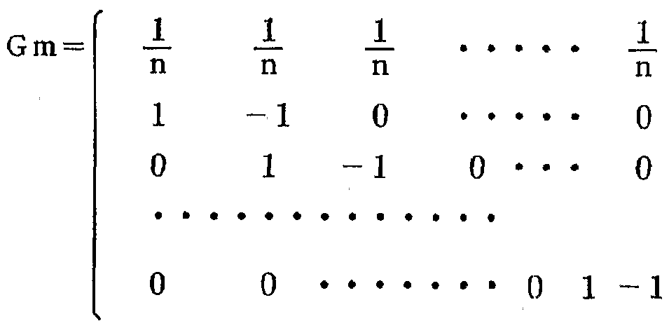
要するに、 温度制御は、 温度の傾斜を意味する情報と、 制御対象の温度の代表を示す 情報、 例えば、 平均の情報とに分離されて行われるようにすればよい。 In short, the temperature control may be performed separately from the information indicating the temperature gradient and the information indicating the representative temperature of the control target, for example, the average information.
第 1の: P I D制御手段 6 iは、 平均温度 ·傾斜温度算出手段 5からの平均温度と目標 平均温度 (平均温度の目標値) の制御偏差に基づいて、 平均温度が目標平均温度になる ように操作信号を配分手段 7に出力する。 First: The PID control means 6i sets the average temperature to the target average temperature based on the control deviation between the average temperature from the average temperature / inclination temperature calculation means 5 and the target average temperature (target value of average temperature). And outputs an operation signal to the distribution means 7.
第 2の P I D制御手段 6 2は、 平均温度 ·傾斜温度算出手段 5からの第 1の傾斜温度 と第 1の目標傾斜温度 (第 1の傾斜温度の目標値) との制御偏差に基づいて、 第 1の傾 斜温度が第 1の目標傾斜温度になるように操作信号を配分手段 7に出力する。 The second PID control means 6 2 based on the control deviation between the first gradient temperature of the first target gradient temperature from the average temperature and gradient temperature calculating means 5 (a target value of the first gradient temperature), An operation signal is output to the distribution means 7 so that the first tilt temperature becomes the first target tilt temperature.
第 3の P I D制御手段 6 3は、 平均温度 ·傾斜温度算出手段 5からの第 2の傾斜温度 と第 2の目標傾斜温度 (第 2の傾斜温度の目標値) との制御偏差に基づいて、 第 2の傾 斜温度が第 2の目標傾斜温度になるように操作信号を配分手段 7に出力する。 The third PID control means 6 3, second gradient temperature from the average temperature and gradient temperature calculating means 5 An operation signal is output to the distribution means 7 based on the control deviation between the second inclination temperature and the second target inclination temperature (the target value of the second inclination temperature) so that the second inclination temperature becomes the second target inclination temperature. I do.
以下同様にして、 第 nの P I D制御手段 6 nは、 平均温度 ·傾斜温度算出手段 5から の第 n— 1の傾斜温度と第 n— 1の目標傾斜温度 (第 n— 1の傾斜温度の目標値) との 制御偏差に基づいて、 第 n— 1の傾斜温度が第 n— 1の目標傾斜温度になるように操作 信号を配分手段 7に出力する。 Similarly, the n-th PID control means 6 n calculates the (n−1) -th slope temperature from the average temperature / slope temperature calculation means 5 and the (n−1) -th target slope temperature (of the (n−1) -th slope temperature). Based on the control deviation from the target value, an operation signal is output to the distribution means 7 so that the (n−1) th ramp temperature becomes the (n−1) th target ramp temperature.
すなわち、 第 1の P I D制御手段 6 は、 平均温度を制御し、 第 2〜第 nの各 P I D 制御手段 6 2〜 6 nは、 第 1〜第 n— 1の傾斜温度をそれぞれ制御する。 That is, the first PID control means 6 controls the average temperature, and the second to n-th PID control means 62 to 6n respectively control the first to n-th gradient temperatures.
次に、 配分手段 7について説明する。 Next, the distribution means 7 will be described.
配分手段 7は、 各 P I D制御手段 6 nからの操作信号 (操作量) を、 各ヒータ l 1〜 l nに配分する。 その配分に際しては、 各 P I D制御手段 6 t〜6 nそれぞれによ る平均温度または各傾斜温度の制御が、 他の P I D制御手段 6 i ~ 6 nそれぞれによる 平均温度または傾斜温度の制御に与える干渉を抑制するように行われる。 The distribution unit 7 distributes an operation signal (operation amount) from each PID control unit 6 n to each of the heaters l 1 to ln. In the distribution, interference of the control of the average temperature or the gradient temperature by each of the PID control means 6 t to 6 n with the control of the average temperature or the gradient temperature by the other PID control means 6 i to 6 n respectively. Is performed so as to suppress.
例えば、 上記配分は、 第 1の P I D制御手段 6 iの操作信号によって平均温度を変化 させる場合に、 その操作信号によって傾斜温度が変化しないように行われる。 また、 第 2の P I D制御手段 6 2の操作信号によって第 1の傾斜温度を変化させる場合に、 その 操作信号によって平均温度および他の傾斜温度が変化しないように行われる。 同様に、 各 P I D制御手段の操作信号によって他の P I D制御手段による制御が影響されないよ うに配分される。 For example, when the average temperature is changed by the operation signal of the first PID control means 6i, the above distribution is performed so that the inclination signal does not change by the operation signal. Further, when the first inclination temperature is changed by the operation signal of the second PID control means 62, the operation is performed so that the average temperature and other inclination temperatures do not change by the operation signal. Similarly, the control signals are distributed so that the control signals of the other PID control means are not affected by the operation signal of each PID control means.
この配分手段 7による配分について、 さらに詳細に説明する。 The distribution by the distribution means 7 will be described in more detail.
ここで、 分かり易くするために、 n == 2、 すなわち、 ゾーンが 2つであって、 第 1 , 第 2のヒータ 1 1 2、 第 1、 第 2の温度センサ 2 2 2、 平均温度を制御する第 1の P I D制御手段 6 i、 両温度センサ 2 1 ; 2 2の検出温度の差である傾斜温度を制御する 第 2の P I D制御手段 6 2を備える 2チャネルの場合に適用して図 4を参照して説明す る。 Here, for simplicity, n == 2, that is, two zones, and the first and second heaters 1 1 2 , the first and second temperature sensors 2 2 2 , and the average temperature the first PID controller 6 i for controlling both the temperature sensor 2 1; FIG applied to the case of two channels with a second PID control means 6 2 for controlling the gradient temperature is the difference between the detected temperature of 2 2 This will be described with reference to FIG.
図 4は、 2入力 2出力の干渉のある制御対象 2 7に適用した例を示している。 図 4に おいて、 図 3に対応する部分には、 同一の参照符号が付される。 2 6い 2 6 2は、 制御 偏差を算出する加算器であり、 図 3においては、 P I D制御手段 6い 6 2に含めて示し ている。 FIG. 4 shows an example in which the present invention is applied to a control target 27 having two-input two-output interference. In FIG. 4, portions corresponding to FIG. 3 are denoted by the same reference numerals. 2 6 There 2 6 2, an adder for calculating a control deviation, in FIG. 3 illustrates included in the PID control means 6 have 6 2.
この制御対象 2 7は、 例えば、 図 5に示されるように、 2入力 (H I , H 2 ) 2出力 (P V 1 , P V2) の干渉のある制御対象である。 この制御対象 27は、 第 1の P I D 制御手段 6 からの第 1の操作量 HIが、 第 1の加算器 28に与えられるとともに、 第 1の減衰器 29で 0.9に減衰されて第 2の加算器 30に与えられる一方、 第 2の P I D制御手段 62からの第 2の操作量 H 2力 第 2の加算器 30に与えられるとともに、 第 2の減衰器 31で 0.9に減衰されて第 1の加算器 28に与えられ、 各加算器 28, 30の加算出力が、 第 1, 第 2の遅れ要素 32, 33にそれぞれ与えられる構成である c この例では、 各操作量 HI, H2が 0.9の割合で他方に加えられて互いに千渉を生じ るものである。 The control target 27 has, for example, two inputs (HI, H2) and two outputs as shown in FIG. (PV 1, PV 2) is the control target with interference. The control target 27 is configured such that the first manipulated variable HI from the first PID control means 6 is supplied to the first adder 28, and is attenuated to 0.9 by the first attenuator 29 to perform the second addition. The second manipulated variable H 2 force from the second PID control means 62 is supplied to the second adder 30 while being attenuated to 0.9 by the second attenuator 31 to the first given to the adder 28, the addition output of the adder 28, 30, first, in the second delay element 32, 33 in a configuration provided respectively c this example, each operation amount HI, H2 0.9 Are added to the other at the rate of
図 4を参照して、 平均温度 ·傾斜温度算出手段 5は、 第 1, 第 2の温度センサ 2 22の検出温度 T2に相当する制御対象 27からのフィードバック量 PV 1, Ρ V 2を、 図 6に示されるように加算器 8で加算し、 減衰器 9で 1/2に減衰して平均温度 Ta Vを出力するとともに、 両温度センサ 2 22の検出温度 1 , T2に相当するフィ ードバック量 PV 1, PV2を減算器 10で減算して傾斜温度 T tを出力する。 Referring to FIG. 4, the average temperature-gradient temperature calculating means 5, the first feedback amount PV 1 from the second temperature sensor 2 2 2 detected temperature T 2 corresponding to the control object 27, the [rho V 2 and adder 8 as shown in FIG. 6, the attenuation to and outputs the average temperature Ta V to 1/2 attenuator 9, corresponding to the detected temperature 1, T 2 of both temperature sensors 2 2 2 The subtractor 10 subtracts the feedback amounts PV1 and PV2 to output the slope temperature Tt.
第 1の P I D制御手段 6 には、 平均温度 ·傾斜温度算出手段 5からの平均温度 T a Vと目標平均温度との制御偏差が加算器 26 を介して与えられる。 第 1の P ID制御 手段 6iは、 その制御偏差に基づいて、 平均温度が目檫平均温度になるように操作信号 '(操作量) Ha Vを配分手段 7に出力する。 The control deviation between the average temperature T aV from the average temperature / inclination temperature calculation means 5 and the target average temperature is given to the first PID control means 6 via the adder 26. The first PID control means 6i outputs the operation signal '(operation amount) Ha V to the distribution means 7 based on the control deviation so that the average temperature becomes the target average temperature.
第 2の P I D制御手段 62には、 平均温度 ·傾斜温度算出手段 5からの傾斜温度 T t と目標傾斜温度との制御偏差が加算器 262を介して与えられる。 第 2の P I D制御手 段 62は、 その制御偏差に基づいて、 傾斜温度が目標傾斜温度になるように操作信号 (操作量) H tを配分手段 7に出力する。 The second PID control means 6 2, control deviation between the gradient temperature T t and the target gradient temperature from the average temperature and gradient temperature calculating means 5 is provided via the adder 26 2. The second PID control hand stage 6 2, based on the control deviation, the operation signal (operation amount) as gradient temperature becomes the target gradient temperature outputs an H t the allocation means 7.
配分手段 7は、 各 P I D制御手段 6 62の操作信号 (操作量) H a V, H tを以下 のような配分比で各ヒータ 11; 1 に配分する。 Allocation means 7, the operation signal (operation amount) of the PID controller 6 6 2 H a V, each heater 1 1 distribution ratio as follows H t; distributed to 1.
すなわち、 図 7は、 図 4のシステムの制御系のブロック線図である。 平均温度を制御 する第 1の P I D制御手段 6 iから与えられる操作量 Ha Vを、 配分手段 7で干渉を抑 制する、 すなわち、 非干渉化するための係数である非干渉化係数 (配分比) k1; k2で 第 1, 第 2のヒータ 1 12にそれぞれ配分するとともに、 第 2の P I D制御手段 62 から与えられる操作量 H tを、 非干渉化係数 (配分比) k3, 4で第1, 第 2のヒータ 1!, 12にそれぞれ配分し、 これによつて、 各ヒ一夕 1 12に熱量 H2がそれぞ れ与えられるとする。 また、 第 1のヒータ Itに与えられた熱量 Hiは、 伝達係数 (干渉係数) しで第1の 温度センサ 2 iに伝わる一方、 伝達係数 (干渉係数) 12で第 2の温度センサ 22に伝わ る。 That is, FIG. 7 is a block diagram of a control system of the system of FIG. The operation amount Ha V given by the first PID control means 6 i for controlling the average temperature is controlled by the distribution means 7 to suppress interference, that is, a decoupling coefficient (a distribution ratio) which is a coefficient for decoupling. ) k 1; first in k 2, respectively as well as distributed to the second heater 1 1 2, an operation amount H t given from the second PID control means 6 2, non-interacting factor (distribution ratio) k 3 , 4 for the first and second heater 1! , 1 2 , respectively, so that the heat quantity H 2 is given to each of the nights 1 1 2 , respectively. The amount of heat Hi given to the first heater It is transmitted to the first temperature sensor 2 i by a transfer coefficient (interference coefficient), while the transfer coefficient (interference coefficient) is 1 2 to the second temperature sensor 2 2. It is transmitted to.
同様に、 第 2のヒータ 12に与えられた熱量 H2は、 伝達係数 (干渉係数) 13で第1 の温度センサ 2 iに伝わる一方、 伝達係数 (干渉係数) 14で第 2の温度センサ 22に伝 わるとする。 Similarly, the amount of heat H 2 given to the second heater 1 2 transfer coefficient (interference coefficient) 1 3 while transmitted to the first temperature sensor 2 i, transfer coefficient (interference coefficient) 1 4 second and Den Waru to the temperature sensor 2 2.
第 1の温度センサ 2 iで検出された検出温度 T tと第 2の温度センサ 22で検出された 検出温度 T2とから平均温度 T a Vおよび傾斜温度 T tが算出されて各 P I D制御手段 61, 62に入力されるという制御ル一プが構成されている。 First detection temperature T t and the average temperature T a V and gradient temperature T t is calculated each PID control from been detected temperature T 2 Metropolitan detected by the second temperature sensor 2 2 detected by the temperature sensor 2 i of control Le one-flop that is input to the means 61, 6 2 are formed.
以上のことから平均温度 T a Vは、 次のように示される。 From the above, the average temperature T a V is shown as follows.
![]()
![]()
= {( 11 · Ηι+ 13 · H2) + ( 12 · Ηι+ 14 - H2)} /2 = {(11 · Ηι + 13 · H 2 ) + (12 · Ηι + 14-H 2 )} / 2
= {( 1 ι+ 12) H,+ ( 13+ 14) H2} /2 = {(1 ι + 1 2 ) H, + (13+ 1 4 ) H 2 } / 2
= {( 11 + 12) (ki · Ha v + k s · H t) = ((11 + 12) (kiHav + ksHt)
+ ( 13+ 14) ( k 2 - Ha v + k4 - H t )} /2 + (13+ 1 4 ) (k 2 -Ha v + k 4 -H t)} / 2
= f{ ( ί 1+ 12) k i+ (】 3+】 4) k2} Ha v = f {(ί 1+ 12) k i + () 3 +] 4 ) k 2 } Ha v
+ {( 1 ! + 12) k3+ ( 13+ 14) k 4} H t〕 / 2 + {(1! + 1 2 ) k 3 + (13+ 1 4 ) k 4 } H t] / 2
ここで、 平均温度 T a vは、 平均温度の操作量 Ha vのみの関数で、 傾斜温度の操作 量 H tの影響を抑制するように、 すなわち、 非干渉化を図るために、 111:の項を0とす る。 Here, the average temperature T av is a function of only the manipulated variable Ha v of the average temperature, and in order to suppress the influence of the manipulated variable H t of the gradient temperature, that is, in order to reduce interference, the term 111: Is set to 0.
すなわち、 ( 1 i + 12) ' k3+ ( 13+ 14) · k4=0 That is, (1 i + 1 2 ) 'k 3 + (13 + 1 4 ) · k 4 = 0
したがって、 k 4=— { ( 1 !+ 12) / ( 13+ 14) } k s Therefore, k 4 = — {(1! + 1 2 ) / (13+ 1 4 )} ks
となる。 Becomes
同様に、 傾斜温度 T tは、 次のように示される。 Similarly, the ramp temperature T t is given by
T t =Τι-Τ2 T t = Τι-Τ 2
= ( 1 i · Ηι+ 1 a · Η2) 一 ( 12 · Ηι+ 14 · Η2) = (1 i · Ηι + 1 a · Η 2 ) one (12 · Ηι + 14 · Η 2 )
= ( 1 ι - 12) Ηι+ (13— ") Η2 = (1 ι-1 2 ) Ηι + (1 3 — ") Η 2
= ( 1 ι - 12) ( k x - Ha v + k3 · H t) = (1 ι - 1 2) (kx - Ha v + k 3 · H t)
+ ( 13- 14) (k2 · Ha v + k* · H t ) + (13- 1 4) (k 2 · Ha v + k * · H t)
= {( 11 - 12) kt+ ( 13- 14) k2} H a v + {( 1 12) ks+ ( 13 - 14) k4} H t = {(11 - 12) kt + (13- 1 4) k 2} H av + {(1 1 2) ks + (1 3 - 1 4) k 4} H t
ここで、 傾斜温度 T tは、 傾斜温度の操作量 H tのみの関数で、 平均温度の操作量 H a Vの影響を抑制するように、 すなわち、 非千渉化を図るために、 :《& の項を0とす る。 Here, the slope temperature T t is a function of only the manipulated variable H t of the slope temperature, so as to suppress the influence of the manipulated variable H a V of the average temperature, that is, to achieve non-interference: Set the term of & to 0.
すなわち、 ( — 1 2) ki+ ( 1 1 *) k2=0 That is, (— 1 2) ki + (1 1 *) k 2 = 0
したがって、 k2 =— {( 1 i - 12) / ( 1 14)} k t Therefore, k 2 = — {(1 i-1 2 ) / (1 1 4 )} kt
となる。 Becomes
以上のことから傾斜温度に影響を与えずに平均温度を制御し、 また、 平均温度に影響 を与えずに傾斜温度を制御する、 すなわち、 平均温度と傾斜温度との千渉をなくした非 干渉制御を行うためには、 各 P ID制御手段 6ぃ 62からの操作量 Hav, H tを、 非 干渉化係数 (配分比) 1^〜]ί4で配分すればよい。 From the above, the average temperature is controlled without affecting the gradient temperature, and the gradient temperature is controlled without affecting the average temperature, that is, non-interference that eliminates interference between the average temperature and the gradient temperature. in order to control the operation amount Hav from the P ID control unit 6 I 6 2, the H t, non-interacting factor (distribution ratio) may be apportioned 1 ^ ~] ί 4.
この非干渉化係数 (配分比)
![]()
![]()
なお、 非干渉化係数 (配分比) ki k*は、 と k2、 k 3と k4との比率がそれぞれ 分かれば、 P I D制御のゲインによって対応できるので、 絶対値は必ずしも必要でない。 伝達係数 (干渉係数) l i l *は、 次のようにして求めることができる。 すなわち、 ヒータを一つだけ変動させて他のヒータは、 一定値に固定、 例えば、 オンのままあるい はオフのままとし、 ヒータの変化量に対する各温度センサの変化量の比率を伝達係数と するのである。 The decoupling coefficient (distribution ratio) ki k * can be dealt with by the gain of PID control if the ratio between k 2 and k 3 and k 3 and k 4 is known, so the absolute value is not necessarily required. The transfer coefficient (interference coefficient) lil * can be obtained as follows. That is, one heater is changed and the other heaters are fixed at a constant value.For example, the heater is kept on or off, and the ratio of the change amount of each temperature sensor to the change amount of the heater is defined as a transfer coefficient. You do it.
例えば、 第 2のヒ一夕 22をオフのままの状態で、 第 1のヒータ を、 ある温度振幅 で変動させたときに、 第 1, 第 2の温度センサ 2 22の検出温度にどの程度の温度振 幅の変動が生じるかによつて伝達係数 1 12を計測することができ、 例えば、 ヒータ を温度振幅 1で変動させたきに、 温度センサの温度振幅が 10であれば、 伝達係数は、 10 (=10/1) となる。 For example, in the state of the second heat Isseki 2 2 off, which the first heater, with variation at a certain temperature amplitude, the first and second temperature sensors 2 2 2 detected temperature The transfer coefficient 1 1 2 can be measured depending on whether or not the temperature amplitude fluctuates to a certain degree.For example, when the heater is fluctuated by the temperature amplitude 1 and the temperature amplitude of the temperature sensor is 10, the transfer coefficient can be measured. The coefficient is 10 (= 10/1).
ここで、 図 4の配分手段 (前置補償器) 7における非干渉化係数 (配分比) を用いた 配分についてさらに具体的に説明する。 制御対象 27の特性は、 上述の図 5に示されて おり、 この特性から伝達係数は、 し=1, 1 =0.9, 1 =0.9, 14=1である。 したがって、 上述の非干渉化係数の式に代入すると、 k4=- { ( 1 i+ 1 2) , ( 1 1 4) } k3 Here, the allocation using the decoupling coefficient (allocation ratio) in the allocation means (pre-compensator) 7 in FIG. 4 will be described more specifically. Characteristics of the controlled object 27 is shown in Figure 5 above, transfer factor from this characteristic, teeth = 1, 1 = 0.9, 1 = 0.9, 1 4 = 1. Therefore, by substituting into the above equation of the decoupling coefficient, k 4 =-{(1 i + 1 2 ), (1 1 4 )} k 3
=- { ( 1 + 0. 9 ) ' ( 0. 9 + 1 )} k ; =-{(1 + 0.9.9) '(0.9.1 + 1)} k;
=— k s = — K s
また、 k 2 =— { ( 1 i- 1 2) / ( 1 s- 1 4) } k i Also, k 2 = — {(1 i- 1 2 ) / (1 s- 1 4 )} ki
=一 { ( 1 - 0. 9 ) / ( 0. 9 - 1 ) } k : となる。 = 1 {(1-0.9) / (0.9-1)} k:
そこで、 仮に各ヒータに配分される熱量の合計が、 Ha Vと等しくなるように、 すな わち、 1^+ 1ί 2= 1となるように設計し、 分かり易さのために、 k3= lという条件を 加える。 Therefore, if the total amount of heat to be distributed to each heater, so as to be equal to Ha V, ie, 1 ^ + 1ί 2 = 1 and so as to design, because of the easy understanding of, k 3 = l is added.
これによつて、 By this,
k 2= k i= 1 / 2 k 2 = ki = 1/2
また、 k — ka=— 1 Also, k — ka = — 1
となり、 配分比 (非干渉化係数) が決定される。 And the allocation ratio (decoupling coefficient) is determined.
つまり、 図 8に示されるように、 平均温度の操作量 Ha Vは、 1 2ずっ各ヒ一タ 1 ! (Hj), 1 2 (H2) に配分し、 傾斜温度の操作量 H tは、 第 1のヒー夕 h (Η^ に は、 そのまま、 第 2のヒータ 12 (H2) には、 符号を変えて配分すればよい。 In other words, as shown in Fig. 8, the manipulated variable Ha V of the average temperature is 1 2 every heater 1! (Hj), allocated to 1 2 (H 2), the operation amount H t of tilt temperature, first heating evening to h (Eta ^ is intact, the second heater 1 2 (H 2), What is necessary is just to change a sign and to distribute.
ここで、 配分比 (非干渉化係数) は、 次のようにして求めることもできる。 Here, the distribution ratio (decoupling coefficient) can also be obtained as follows.
すなわち、 上述のモード変換行列 Gmと上述の伝達係数 (干渉係数) の行列 Pとから 配分比 (非干渉化係数) の行列 . (以下 「前置補償行列」 ともいう) Gcは、 以下のよう に逆行列として求めることもできる。 That is, from the above-mentioned mode conversion matrix Gm and the above-described transfer coefficient (interference coefficient) matrix P, a distribution ratio (decoupling coefficient) matrix. (Hereinafter also referred to as “pre-compensation matrix”) Gc is as follows: Can be obtained as an inverse matrix.
Gc= (Gm · P) -1 Gc = (GmP) -1
この実施の形態に適用すると、 制御対象のある時間の特性である伝達係数 (干渉係 数) の行列 Pを、 When applied to this embodiment, a matrix P of a transfer coefficient (interference coefficient), which is a characteristic of a controlled object at a certain time, is given by
【数 3】 [Equation 3]
P = 1 P = 1
1 0.9 1 0.9
0.9 1 とすると、 配分比 (非干渉化係数) の行列である前置補償行列 G cは、 【数 4】 0.9 1 Then, the pre-compensation matrix G c, which is the matrix of the distribution ratio (decoupling coefficient), is given by
G c = G c =

【数 5】 [Equation 5]
Gm - P · G c Gm-PGc

ここで、 配分比 (非干渉化係数) の行列である前置補償行列 G cが、 上述のようにモ 一ド平均行列 Gmと伝達係数 (干渉係数) の行列 Pとの積の逆行列として求めることが できる理由について詳細に説明する。 Here, the pre-compensation matrix G c, which is the matrix of the distribution ratio (decoupling coefficient), is the inverse matrix of the product of the mode average matrix Gm and the matrix P of the transfer coefficient (interference coefficient), as described above. I explain in detail why we can ask.
先ず、 図 9に基づいて、 公知の非干渉化制御と前置補償器について説明する。 First, a known decoupling control and pre-compensator will be described with reference to FIG.
同図において、 6 i S mは P I D制御手段、 7は前置補償器、 3は干渉のある制御 対象、 3 ' は非干渉化後の制御対象を示している。 In the figure, 6 i Sm denotes PID control means, 7 denotes a pre-compensator, 3 denotes a control target having interference, and 3 ′ denotes a control target after decoupling.
一般的に知られている非干渉化制御として、 入力、 出力ともに m個ある制御対象 3 の制御系の設計について考える。 その伝達関数行列を G p ( s ) とする。 このように 多数の入力と出力のある系では、 干渉があるために一つの入力だけを変えてもその影 響は m個の出力すべてに出る。 As a generally known decoupling control, let us consider the design of a control system for a control target 3 that has m inputs and outputs. Let the transfer function matrix be G p (s). in this way In a system with many inputs and outputs, even if only one input is changed due to interference, the effect is reflected on all m outputs.
したがって、 ある出力一つだけを動かすためにどれかの入力を変えると、 動かした くない出力まで変動してしまう。 そこで関連の深い入力と出力とを 1対 1に対応させ て、 一つの入力を変えたときには、 対 、する出力だけが変化するようにできればよい。 このことを非干渉化 (Decoupling) という。 Therefore, if you change any of the inputs to move only one output, it will fluctuate to the output you do not want to move. Therefore, it is only necessary to make one-to-one correspondence between closely related inputs and outputs so that when one input is changed, only the corresponding output changes. This is called decoupling.
制御対象の伝達関数行列 Gp (s ) が、 もし対角行列であれば非干渉性はすでに成 り立っているわけであるが、 一般に Gp (s) は対角行列ではないので、 制御対象 3 の前に前置補償器 7と呼ばれる制御器を置く。 この前置補償器 7の伝達関数行列を G c ( s ) と書く ことにすると、 Gp (s) G c ( s ) を対角行列になるように G c (s) を定めれば非干渉化が達成できるわけである。 いったん対角化ができると 1入 力 1出力の関係が m個独立に存在することになり、' その一つづつに対して P I D制御 を用いて制御すればよく、 図 9 (b) のような構成になる。 If the transfer function matrix Gp (s) of the controlled object is a diagonal matrix, the incoherence has already been established, but in general, Gp (s) is not a diagonal matrix. Is placed in front of a controller called precompensator 7. If the transfer function matrix of this precompensator 7 is written as G c (s), if G c (s) is determined so that Gp (s) G c (s) becomes a diagonal matrix, non-interference Can be achieved. Once diagonalization is possible, there will be m independent relationships between one input and one output, and it is sufficient to control each one using PID control, as shown in Fig. 9 (b). Configuration.
さて Gp (s ) G c ( s ) が対角行列 (行列の対角線に値が直線上に並び、 三角形 の部分が 0である行列) になるように Gcを求めることであるが、 その最も単純な方 法は Gp (s) Gc (s ) = 1から求まる。 両辺に左側から Gp (s)一1をかけるとす ると、 Now, the Gc (s) Gc (s) is to find Gc so that it becomes a diagonal matrix (a matrix in which the values are arranged on a straight line on the diagonal of the matrix and the triangle part is 0). Is obtained from Gp (s) Gc (s) = 1. If you from the left side to both sides and make a Gp (s) one 1,
Gp (s)_1Gp ( s ) Gc ( s ) 二 Gp(s) -1 Gp (s) _1 Gp (s) Gc (s) Gp (s) -1
となり Gp (s)一1 Gp (s ) =1なので Next Gp (s) one 1 Gp (s) = 1, so
G c ( s ) =Gp (s )一1 G c (s) = Gp (s) -1
となる。 したがって、 前置補償器 7の伝達関数行列 Gc (s) は、 制御対象 3'の伝達 闋数行列 G p ( s )の逆行列で求まることになる。 Becomes Therefore, the transfer function matrix Gc (s) of the precompensator 7 is obtained by the inverse matrix of the transfer function matrix Gp (s) of the controlled object 3 ′.
次に、 図 10に基づいて、 傾斜温度を制御する本発明における前置補償器 (配分手 段) 7について説明する。 Next, based on FIG. 10, the pre-compensator (distribution means) 7 in the present invention for controlling the gradient temperature will be described.
本発明における前置補償器 7の役割は 2つある。 主要な役割は、 平均と傾斜の温度 の操作量 MVを各 c hに適切に配分する手段である。 副次的な役割として公知の非干 渉化制御の非干渉化がある。 The precompensator 7 in the present invention has two roles. The main role is to allocate the manipulated variables MV of the mean and slope temperature appropriately to each ch. A secondary role is the decoupling of known decoupling control.
本発明では、 例えば、 平均と傾斜とで制御するので P I Dの出力である操作量 MV も平均と傾斜で求まる。 平均と傾斜の MVを c h毎に (MVl〜MVm〉 に分配する には制御対象 3の前に配分するための手段がどうしても必要であり、 そのために前置 補償器 7を利用したのである。 非干渉化は副次的なものであり、 積極的に非干渉化を しているわけではない。 In the present invention, for example, since the control is performed by the average and the slope, the manipulated variable MV, which is the output of the PID, is also obtained by the average and the slope. In order to distribute the average and gradient MVs to each channel (MVl to MVm), a means for distributing them before control target 3 is absolutely necessary. Compensator 7 was used. Decoupling is a secondary matter and does not mean that it is actively decoupling.
したがって制御対象 3の関係を省略して、 干渉のない制御対象と近似して前置補償 器 7を求めても構わない。 これだけでもかなりの効果がある。 Therefore, the pre-compensator 7 may be determined by omitting the relationship of the control target 3 and approximating the control target without interference. This alone has a considerable effect.
公知の非千渉化制御の前置補償器 Gc (s) は制御対象 Gp (s) の逆行列であつ たが、 本発明の傾斜温度制御の場合、 制御対象の部分が、 Gm (s) Gp (s ) に相 当するので、 Gm ( s ) Gp ( s ) Gc ( s ) = 1から求める。 The pre-compensator Gc (s) of the known non-interference control is the inverse matrix of the control target Gp (s) .In the case of the gradient temperature control of the present invention, the control target part is Gm (s). Since it is equivalent to Gp (s), it is determined from Gm (s) Gp (s) Gc (s) = 1.
両辺に左側から (Gm (s) Gp ( s )) 1を掛ける。 すると Multiply both sides by (Gm (s) Gp (s)) 1 from the left. Then
(Gm ( s ) Gp ( s )) -1 Gm ( s ) Gp ( s ) Gc ( s ) (Gm (s) Gp (s))- 1 Gm (s) Gp (s) Gc (s)
= (Gm (s ) Gp ( s )) -1 = (Gm (s) Gp (s))- 1
となり、 (Gm ( s ) Gp ( s )) — (s ) Gp ( s ) = Iなので、 (Gm (s) Gp (s)) — (s) Gp (s) = I,
Gc ( s ) = (Gm ( s ) Gp (s )) -1 Gc (s) = (Gm (s) Gp (s))- 1
となる。 したがって、 前置補償器 (配分手段) 7の伝達関数行列 Gc (s) は、 制御 対象 3の伝達関数行列 Gp (s) とモード変換器 (平均温度傾斜温度算出手段) 5の 伝達関数行列 (モード変換行列) Gm (s) の積の逆行列で求まるのである。 Becomes Therefore, the transfer function matrix Gc (s) of the precompensator (distribution means) 7 is the transfer function matrix Gp (s) of the controlled object 3 and the transfer function matrix (the average temperature gradient temperature calculating means) 5 (Mode conversion matrix) It is obtained by the inverse matrix of the product of Gm (s).
上述の図 4のシステムでは、 配分手段 7では、 図 8に示されるように、 平均温度の操 作信号 (操作量) Havは、 各減衰器 11, 12でそれぞれ 1/2に減衰して加算器 1 3および減算器 14にそれぞれ配分され、 傾斜温度の操作信号 (操作量) H tは、 加算 器 13および減算器 14にそれぞれ配分され、 加算器 13の出力 Hiが第 1のヒータ に、 減算器 14の出力 H2が第 2のヒータ 12に与えられる。 In the system of FIG. 4 described above, in the distribution means 7, as shown in FIG. 8, the operating signal (operating amount) Hav of the average temperature is attenuated to 1/2 by each of the attenuators 11 and 12, and added. The operating signal (operating amount) Ht of the gradient temperature is distributed to the adder 13 and the subtractor 14, respectively, and the output Hi of the adder 13 is supplied to the first heater. output of H 2 subtracter 14 is applied to the second heater 1 2.
この配分手段 7によれば、 平均温度の操作量 Ha Vによって平均温度を変化させる場 合には、 各ヒ一夕 li, 12に操作量が等しく配分されるので、 傾斜温度に影響を与える ことなく、 すなわち、 干渉することなく、 平均温度のみを変化させることができる。 ま た、 傾斜温度の操作量 H tによって傾斜温度を変化させる場合には、 一方のヒータ には、 その操作量が 1倍で与えられる一方、 他方のヒータ 12には、 —1倍で与えられ るので、 両ヒータに与える総熱量を変化させることなく、 すなわち、 平均温度に影響を 与えることなく、 傾斜温度のみを変化させることができる。 According to the allocation means 7, a case of changing the average temperature by the operation amount Ha V of the average temperature, since the operation amount is distributed equally to each heat Isseki li, 1 2, influence the gradient temperature Without, that is, only the average temperature can be changed without interference. Also, in the case of changing the gradient temperature by the operation amount H t of tilt temperature is one of the heater, while the operation amount is given in 1x, to the other heater 1 2, given by -1 times Therefore, only the gradient temperature can be changed without changing the total amount of heat applied to both heaters, that is, without affecting the average temperature.
次に、 図 4に示される実施の形態と、 図 13に示される従来例とのシミュレーション の結果を以下に説明する。 なお、 図 13において、 25い 252は、 P I D制御手段で ある。 このシミュレーションでは、 以下のような制御対象のモデリングを行った。 すなわち、 熱干渉系の最も簡単な例として、 図 1 1に示すように 2組のヒー夕 1 12と温度セン サ 2 22と、 その間を熱伝導体 50でつないだ熱処理装置を考える。 制御目的は、 2 点の温度を任意の設定温度で均一化することである。 図 1 2に制御対象の電気的な等価 回路を示す。 Ri, R2は、 温度センサから周囲の空気への熱抵抗、 d, C2は、 温度セ ンサ近傍の熱容量である。 Next, simulation results of the embodiment shown in FIG. 4 and the conventional example shown in FIG. 13 will be described below. In FIG. 13, 25 have 25 2 is a PID controller. In this simulation, the following controlled objects were modeled. That is, as the simplest example of the thermal interference system, two sets of heating evening 1 1 2 and the temperature sensor 2 2 2 As shown in FIG. 1 1, consider the heat treatment apparatus was connected with the thermal conductor 50 therebetween. The purpose of the control is to make the two temperatures uniform at an arbitrary set temperature. Figure 12 shows the electrical equivalent circuit of the control target. Ri, R 2, the thermal resistance from the temperature sensor to the ambient air, d, C 2 is the heat capacity in the vicinity of the temperature sensor.
制御対象の入力は、 2つのヒータ熱量であり、 ヒー夕 1 tの熱量 の一部は熱伝導体 50を伝わって、 熱抵抗 R3で温度センサ 22の温度 S 2に干渉し、 ヒータ 12の熱量 p 2 の一部は、 同様に熱抵抗 R3で温度センサ 2 の温度 S に干渉する。 また、 熱量 p 2の一 部の熱エネルギーは、 熱抵抗 で熱処理装置が固定されている機械装置本体に熱伝導 する。 ただし、 機械装置本体の熱容量は、 非常に大きいので、 周囲温度と一致すると近 似した。 The input of the controlled object is the two heater heat amounts. A part of the heat amount of 1 t of the heater is transmitted through the heat conductor 50 and interferes with the temperature S 2 of the temperature sensor 2 2 with the heat resistance R 3 , and the heater 1 some of the second heat p 2 is likewise interfere with the temperature S of the temperature sensor 2 in the thermal resistance R 3. The thermal energy of the part of the heat p 2 is conducted to the machine body heat treatment apparatus in thermal resistance is fixed. However, the heat capacity of the machine was very large, so it was close to the ambient temperature.
制御対象の等価回路のパラメータは、 1^ = 1 2=10 [°CZW]、 Rs=l [°C/W],
![]()
![]()
下記の表 1のパラメータによる従来の P I D制御の応答波形を図 14に、 下記の表 2 のパラメータによるこの実施の形態の応答波形を、 図 1 5に示す。 FIG. 14 shows the response waveform of the conventional PID control using the parameters shown in Table 1 below, and FIG. 15 shows the response waveform of this embodiment using the parameters shown in Table 2 below.
【表 1】 【table 1】

このような特性の差を生み出せる理由は、 この実施の形態では、 傾斜温度と平均温度 で独立に P I Dパラメータを設定できる点にある。 この例では、 表 2に示すように比例 ゲイン K pに差をつけ平均温度よりも傾斜温度の収束を優先するように、 傾斜温度制御 の比例ゲイン K pを平均温度制御の比例ゲイン K pよりも大きな値に設定した。 その結 果、 簡単な P I D制御のパラメータの設定であるにも関わらず、 高精度な温度均一化を 期待できるものである。 The reason for producing such a difference in characteristics is that in this embodiment, the PID parameter can be set independently for the slope temperature and the average temperature. In this example, as shown in Table 2, the proportional gain Kp is made different from the proportional gain Kp Was also set to a large value. As a result, high-precision temperature uniformity can be expected despite simple PID control parameter settings.
さらに、 この実施の形態と従来例との目標値応答および外乱応答の比較結果を、 図 1 6〜図 1 9に示す。 なお、 ここでは、 C H R (Chien, Hrones and Reswi ck) の調整則 の目標値応答オーバーシユート無しを平均温度制御に、外乱応答オーバ一シユート 2 0 %を傾斜温度制御に使用した。 FIGS. 16 to 19 show comparison results of the target value response and the disturbance response between the embodiment and the conventional example. Here, in the adjustment rule of CHR (Chien, Hrones and Reswick), no target value response overshoot was used for average temperature control, and disturbance response overshoot 20% was used for gradient temperature control.
図 1 6および図 1 7が、 この実施の形態の目標値応答および外乱応答の波形であり、 図 1 8および図 1 9が、 従来例の目標値応答および外乱応答の波形を示している。 図 1 8の従来例の目標値応答では、 整定時間も 2 9秒と長く、 オーバ一シュ一トも認 められたけれども、 この実施の形態の目標値応答では、 図 1 6に示されるように整定時 間も 9秒と短く、 ォ一バーシュートも認められなかつた。 FIGS. 16 and 17 show the waveforms of the target value response and the disturbance response of this embodiment, and FIGS. 18 and 19 show the waveforms of the target value response and the disturbance response of the conventional example. Although the settling time was as long as 29 seconds and an overshoot was observed in the target value response of the conventional example in FIG. 18, the target value response in this embodiment was as shown in FIG. 16. The settling time was as short as 9 seconds, and no overshoot was observed.
また、 図 1 9の従来例の外乱応答では、 整定時間も 3 2秒と長く、 オーバ一シュート もやや認められたのに対して、 この実施の形態の外乱応答では、 図 1 7に示されるよう に、 整定時間も 6秒と短く、 オーバーシュートも認められなかった。 Further, in the disturbance response of the conventional example in FIG. 19, the settling time was as long as 32 seconds and overshoot was slightly recognized, whereas in the disturbance response of this embodiment, it is shown in FIG. Thus, the settling time was as short as 6 seconds, and no overshoot was observed.
すなわち、 この実施の形態では、 平均温度制御は、 弱くて遅い制御を、 傾斜温度制御 は、 強くて速い制御を行ったので、 目標値応答および外乱応答のいずれの場合も、 ォー バーシュートがなく整定時間も短く満足できるものとなった。 That is, in this embodiment, the average temperature control performed weak and slow control, and the gradient temperature control performed strong and fast control. Therefore, in both the target value response and the disturbance response, the overshoot was reduced. The settling time was short and satisfactory.
上述の例では、 簡単にするために、 n = 2の場合について説明したけれども、 ゾーン が 3つの場合、 すなわち、 ヒータ、 温度センサおよび P I D制御手段が 3つの n = 3の 3チャネルの場合にも同様に適用できるものである。 In the above example, for simplicity, the case of n = 2 has been described. However, in the case of three zones, that is, three heaters, temperature sensors, and three PID control means, three channels of n = 3 It is equally applicable.
すなわち、 上述の図 7に対応する図 2 0のブロック線図に示されるように、 第 1〜第 3のヒ一夕 1 i〜 1 3と、 各ヒータ 1 〜 1 3に個別的に対応する第 1〜第 3の温度センサ S ! S sとが、 第 1〜第 3の各ゾーンにそれぞれ配置されており、 第 1のゾーンと第 2 のゾーンとが隣接し、 第 2のゾーンと第 3のゾーンとが隣接しているとし、 簡単化のた めに、 隣接するゾーン間でのみ干渉があるとし、 第 1のヒータ I tから第 2の温度セン サ 22への伝達係数 (干渉係数) を 1 第 2のヒータ 12から第 1, 第 3の温度センサ 21, 23への伝達係数 (干渉係数) を 12 13、 第 3のヒータ 13から第 2の温度セン サ 22への伝達係数 (干渉係数) を 14とし、 第 1のヒ一夕 から第 1の温度センサ 2i といった相対する伝達係数 (干渉係数) は、 1.0とする。 That is, as shown in the block diagram of Figure 2 0 corresponding to FIG. 7 described above, the first to third heat Isseki 1 i to 1 3, corresponding individually to each of the heaters 1-1 3 The first to third temperature sensors S! Ss are respectively disposed in the first to third zones, the first zone and the second zone are adjacent to each other, and the second zone and the Zone 3 is adjacent, and for simplicity, it is assumed that there is interference only between adjacent zones. Sa 2 transfer coefficient to 2 (interference coefficient) of 1 second heater 1 2 from the first, third temperature sensor 21, 2 transfer coefficient to 3 (interference coefficient) 1 2 1 3, the third heater 1 from 3 and the second temperature sensor 2 transfer coefficient to 2 (interference coefficient) 1 4, opposed transfer coefficient such as a first temperature sensor 2i from the first heat Isseki (interference coefficient) is 1.0 I do.
また、 干渉をなくすための非干渉化係数 (配分比) について、 平均温度を制御する第 1の P I D制御手段 6 ,の操作量 Ha Vを第 2, 第 3のヒータ 12, 13に配分するため の非干渉化係数 (配分比) を 1^, k2、 第 1の傾斜温度 T t iを制御する第 2の P I D 制御手段 62の操作量 H t tを第 1, 第 3のヒータ 1 13に配分するための非千渉化係 数 (配分比) を k3, k4、 第 2の傾斜温度 T t 2を制御する第 3の P I D制御手段 63の 操作量 H t 2を第 1, 第 2のヒータ 1 12に配分するための非干渉化係数 (配分比) を k5, k6とし、 第 1の P I D制御手段 6 iから第 1のヒ一夕 1 iといった相対する非干 渉化係数は 1.0とする。 なお、 この例では、 第 1の傾斜温度 T t 1は、 第 2, 第 3の 温度センサ 22, 23の検出温度て2, T3の平均の検出温度と第 1の温度センサ 2 iの検 出温度 との差としており、 また、 第 2の傾斜温度 T t 2は、 第 2の温度センサ 22の 検出温度 T2と第 3の温度センサ 23の検出温度 T3との差としている。 Moreover, non-interference coefficients for eliminating interference for (distribution ratio), distribution first PID control means 6 for controlling the average temperature, the amount of operation Ha V to the second, third heater 1 2, 1 3 The decoupling coefficient (distribution ratio) is 1 ^, k 2 , and the operation amount H tt of the second PID control means 62 for controlling the first gradient temperature T ti is the first and third heaters 1. 1 Hisen Watarrka coefficient for distributing the 3 (distribution ratio) k 3, k 4, the operation amount H t 2 of the third PID controller 63 for controlling the second gradient temperature T t 2 a 1, non-interference coefficients for distributing the second heater 1 1 2 (distribution ratio) and k 5, k 6, opposite such first heat Isseki 1 i from the first PID control means 6 i The de-interference factor is 1.0. In this example, the first gradient temperature T t 1, the second, third temperature sensor 2 2, 2 3 of the detected temperature on 2, the temperature detected by the average of T 3 and the first temperature sensor 2 i detection is a difference between the temperature, also the second gradient temperature T t 2, the difference between the detected temperature T 2 of the second temperature sensor 2 2 and the third detected temperature T 3 of the temperature sensor 2 3 And
このとき、 平均温度 T a Vは、 次のように示される。 At this time, the average temperature T a V is expressed as follows.
![]()
![]()
- {(Ηι+ 12 · H2) + ( 11 · Ηι+Ήζ+ 14 · Hs)- {(Ηι + 12 · H 2) + (11 · Ηι + Ή ζ + 1 4 · Hs)
![]()
![]()
= {(1 + 1 H!+ (1 + 12+ 13) H2+ (1 + 14) Hs} /3 = {(1 + 1 H! + (1 + 12+ 13) H 2 + (1 + 1 4 ) Hs} / 3
= l + l J (Hav + k s- H ti + k s - H t z) = l + l J (Hav + ks-Hti + ks-Htz)
+ (1 + 12+ 13) (ki · H a v + H t ! + k e · H t 2) + (1+ 14) (k2 · H a v + k4 · H t x + H 12) } /3 + (1 + 12+ 1 3) (ki · H av + H t! + Ke · H t 2) + (1+ 1 4) (k 2 · H av + k 4 · H tx + H 1 2)} / 3
= [{(1 + 1!) + (1 + 12+ 13) ki+ ( 1 + 14) k2} Hav = [{(1 + 1!) + (1 + 12 + 1 3 ) ki + (1 + 1 4 ) k 2 } Hav
+ {(1 + 1 i) k3+ (1 + 12+ 13) + (1 + 14) k*} H t ! + {(1 + 1 i) k 3 + (1 + 12+ 13) + (1 + 1 4 ) k *} H t!
+ {(1 + 1 i) k5+ ( 1 + 12+ 13) k6+ ( 1 + 14) } H t 2] / 3 + {(1 + 1 i) k 5 + (1 + 12 + 13) k 6 + (1 + 1 4 )} H t 2] / 3
ここで、 平均温度 T a vは、 平均温度の操作量 Ha vのみの関数で、 傾斜温度の操作 量 H ti, H 12の操作量の影響をなくすように、 すなわち、 非干渉化を図るために、 H t 1 , H t 2の項を 0とする。 Here, the average temperature T av is a function of only the manipulated variable Ha v of the average temperature, so as to eliminate the influence of the manipulated variables H ti and H 1 2 of the gradient temperature, that is, to reduce interference. And the terms H t 1 and H t 2 are set to 0.
すなわち、 (1 + 1 k s+ (1+ 12+ 13) + (1+ 14 k 4= 0 ( 1 + 1 x) k5+ (1 + 12+ 1 s) k6+ ( 1 + 14) =0 となる。 That is, (1 + 1 k s + (1 + 12 + 1 3 ) + (1 + 1 4 k 4 = 0 (1 + 1 x) k 5 + (1 + 12 + 1 s) k 6 + (1 + 14) = 0.
これを以下のように簡略化する。 This is simplified as follows.
1 a + 1 b · k3+ 1 c · k4= 0 ……① 1 a + 1 b · k 3 + 1 c · k 4 = 0 …… ①
1 d+ 1 e · k5+ 1 f ■ k6=0 ……② 1 d + 1 e · k 5 + 1 f ■ k 6 = 0 …… ②
第 1の傾斜温度 T t tについても同様にして、 第 1の傾斜温度の操作量 H t iのみの閧 数で、 平均温度の操作量 H a Vおよび第 2の傾斜温度の操作量 H 12の影響を受けない という条件を適用して、 以下のような同様の方程式が得られる。In the same manner for the first gradient temperature T tt, only the operation amount H ti of the first inclined temperature閧number, the average temperature manipulation amount H a V and the second gradient temperature operation amount H 1 2 Applying the unaffected condition, one obtains a similar equation:
![]()
![]()
1 j + 1 k · k5+ 1 i · k6= 0 ……④ 1 j + 1 k · k 5 + 1 i · k 6 = 0 …… ④
また、 第 2の傾斜温度 T 12についても同様に、 以下の方程式が得られる。 Similarly, the following equation is obtained for the second gradient temperature T12.
![]()
![]()
1 + 1 q · ks+ 1 r · k4= 0 "…-⑥ 1 + 1 q · ks + 1 r · k 4 = 0 "… -⑥
伝達係数し〜 14、 したがって、 l a~ l rは、 n = 2の場合と同様にして求められ るので、 非干渉化係数 k t〜 k 6を未知数とする上記①〜⑥の 6つ方程式が得られること になり、 これら方程式を解くことにより、 配分手段で配分するための非干渉化係数 (配 分比) kL ksが求まることになる。 Transfer coefficient was ~ 1 4, therefore, la ~ lr is, n = 2 when the determined in the same manner Runode, six equations above ①~⑥ to the decoupling coefficient Kt~ k 6 unknowns obtained By solving these equations, the decoupling coefficient (allocation ratio) kL ks for allocation by the allocation means can be obtained.
例えば、 行列式で求めるとすれば、 以下のようになる。 For example, if it is obtained by the determinant, it is as follows.
【数 6】 [Equation 6]
0 0 lb u 0 0 0 0 lb u 0 0
0 0 0 0 te If 0 0 0 0 te If
lh li 0 0 0 0 lh li 0 0 0 0
二 0 Two 0
0 0 0 0 Ik li 0 0 0 0 Ik li
In lo 0 0 0 0 In lo 0 0 0 0

![]()
![]()
【数 7】

なお、 配分比 (非干渉化係数) の行列である前置補償行列 Gcは、 上述のように、 モ —ド変換行列 Gmと伝達係数 (干渉係数) の行列 Pとから求めることもでき、 第 1の P I D制御手段 6 iから第 1のヒータ liといった相対する非干渉化係数も含めて求めるこ とができる。 ここで、 制御対象のある時間の特性である伝達係数 (干渉係数) の行列 P を、 The pre-compensation matrix Gc, which is the matrix of the distribution ratio (decoupling coefficient), can also be obtained from the mode conversion matrix Gm and the matrix P of the transfer coefficient (interference coefficient), as described above. It can be obtained from the PID control means 6i as well as the relative decoupling coefficients such as the first heater li. Here, the matrix P of the transfer coefficient (interference coefficient), which is the characteristic of the controlled
【数 8】 [Equation 8]
P = 1 P = 1
14 仮に、 1 = 12= 13= 14=0.9とすると, 1 4 Assuming 1 = 1 2 = 1 3 = 1 4 = 0.9,
【数 9】 [Equation 9]
1 0.9 0 1 0.9 0
P = 0.9 1 0.9 P = 0.9 1 0.9
0 0.9 1 前置補償行列 Gcは、 0 0.9 1 The pre-compensation matrix Gc is
【数 10】

' -0. 1613 - 0. 2527 1. 2527 '-0.1613-0.22527 1.2527
1. 2903 1. 0215 -1. 0215 1. 2903 1. 0215 -1. 0215
-0. 1613 -1. 0227 0. 2527 確かめとして、 Gm · P G c - Iとなるかどうかを計算する < -0. 1613 -1. 0227 0.2527 As a check, calculate whether Gm · P G c-I <
【数 1 1】 [Equation 1 1]
G m · P · G c G m · P · G c
1 1 1 1 1 1
1 0. 9 0 1 0.9.0
3 3 3 -0. 1613 -0. 2527 1. 2527 3 3 3 -0. 1613 -0.25 27 1.2527
1 -1 0 0. 9 1 0. 9 1.2903 1. 0215 -1. 0215 1 -1 0 0.9 1 0.9 1.2903 1.0215 -1. 0215
0 1 - 1 L 0 0. 9 1 -0. 1613 - 1. 0227 0. 2527

上述のように、 配分比 (非干渉化係数) の行例である前置補償行列 G cは、 モード変 換行列 Gmと伝達係数 (干渉係数) の行列 Pとの積の逆行列として求めることができる。 したがって、 前置補償行列 G cを求めるには、 上述のように伝達係数 (千渉係数) の 行列 Pを知る必要がある。 As described above, the pre-compensation matrix G c, which is an example of the distribution ratio (decoupling coefficient), is determined as the inverse matrix of the product of the mode conversion matrix Gm and the matrix P of the transfer coefficient (interference coefficient). Can be. Therefore, in order to obtain the pre-compensation matrix G c, it is necessary to know the matrix P of the transfer coefficient (coefficient of interference) as described above.
なお、 伝達係数に代えて、 周波数特性も表す伝達関数を用いてもよいので、 以下にお いては、 伝達関数 (干渉係数) として、 その行列 Pの計測方法の具体例を説明する。 図 2 1は、 本発明の実施の形態に係るステップ応答法を利用した伝達関数 (干渉係 数) の行列 Pの計測方法を説明するための操作量 MVおよびフィードバック量 P Vの変 化を示す図である。 Note that a transfer function that also represents frequency characteristics may be used instead of the transfer coefficient, and a specific example of a method of measuring the matrix P as a transfer function (interference coefficient) will be described below. FIG. 21 is a diagram showing changes in the manipulated variables MV and feedback amounts PV for explaining a method of measuring the matrix P of the transfer function (interference coefficient) using the step response method according to the embodiment of the present invention. It is.
例えば、 図 2 2に示される温度制御システム、 すなわち、 制御対象 3を加熱する第 0 から第 nの複数のヒータ 1。〜1 nと、 各ヒータ 1。~1 nに個別的に対応して制御対象 3の温度を検出する第 0から第 nの複数の温度センサ 2。〜 2 nと、 これら温度センサ 20〜 2 nの検出出力に基づいて、 各ヒータ 1。~1 nを図示しない電磁開閉器などを介 して操作して制御対象 3の温度を制御する本発明に係る温度調節器 4とを備えているシ ステムにおいて、 図 21 (a) 〜 (d) に示されるように各ヒータ lo〜l nに順番に ステップ状の操作量 MVO, MVl MVnを与え、 図 21 (e) ~ (h) に示される 各温度センサ 2。〜2 nからのフィードバック量である検出温度 PV0, PV 1〜PV nに基づいて、 一定時間 t m後の上昇直前の温度に対する温度上昇値 Δ P Vを単位時間 Lで割った値 APVZLを、 下記に示される干渉係数 (伝達関数) の行列 Pの a00〜a nnとして設定するものである。 . For example, the temperature control system shown in FIG. Nth multiple heaters from 1 ~ 1 n and each heater 1. A plurality of 0th to nth temperature sensors 2 for detecting the temperature of the control target 3 individually corresponding to ~ 1 n. ~ And 2 n, based on the detection output of the temperature sensor 2 0 ~ 2 n, each heater 1. FIGS. 21 (a) to 21 (d) show a system including a temperature controller 4 according to the present invention for controlling the temperature of the control target 3 by operating ~ 1 n via an electromagnetic switch (not shown). ), Stepwise manipulated variables MVO, MVl and MVn are sequentially applied to the heaters lo to ln as shown in FIG. 21), and the temperature sensors 2 shown in FIGS. 21 (e) to (h). Based on the detected temperature PV0, PV1 to PVn, which is the feedback amount from ~ 2n, the temperature rise value ΔPV with respect to the temperature just before the rise after a fixed time tm, ΔPV, divided by the unit time L, APVZL, It is set as a 00 to a nn of the matrix P of the indicated interference coefficient (transfer function). .
なお、 本発明の他の実施の形態として、 単位時間 Lで割らなくてもよい。 また、 図 2 2では、 下記に示される伝達関数 (干渉係数) の行列 Pの各要素 a00〜annとの対応が 明瞭になるように、 上述の図 1とは、 ヒータおよび温度センサの参照符号のみを異なら せて示しているが、 構成は上述と同様である。 Note that in another embodiment of the present invention, it is not necessary to divide by the unit time L. Further, in FIG. 22 , in order to clarify the correspondence between the elements a 00 to ann of the matrix P of the transfer function (interference coefficient) shown below, FIG. Although only the reference numerals are shown differently, the configuration is the same as described above.
【数 12】 (Equation 12)

以下同様にして、 第 nのヒー夕に図 21 (d) に示されるステップ状の操作量 MVn を与えたときの図 21 (e) に示される第 0の温度センサ 2。の検出温度 PV 0に基づ く単位時間当たりの温度上昇値 ΔΡ VZLを a。nとし、 図 21 ( f ) に示される第 1の 温度センサ 2 tの検出温度 P V 1に基づく単位時間当たりの温度上昇値 Δ P VZLを a i nとし、 図 21 (g) に示される第 2の温度センサ 22の検出温度 PV2に基づく単位時 間当たりの温度上昇値 ΔΡν/Lを a2nとし、 同様に、 図 21 ( ) に示される第 nの 温度センサ 2 nの検出温度 P V nに基づく単位時間当たりの温度上昇値 Δ P V/Lを a nnとするものである。 なお、 図 21においては、 t cは、 操作量 MVの変化に対して検 出温度 PVの変化が安定するまでの一定時間である。 Similarly, the 0th temperature sensor 2 shown in FIG. 21 (e) when the step-like manipulated variable MVn shown in FIG. 21 (d) is given to the nth heater. Temperature rise per unit time based on the detected temperature PV 0 ΔΡ VZL a. and n, the temperature rise value delta P VZL per unit time based on the detected temperature PV 1 of the first temperature sensor 2 t as shown in FIG. 21 (f) and ai n, second, shown in FIG. 21 (g) the temperature rise value ΔΡν / L per during unit time based on the temperature sensor 2 2 detected temperature PV2 and a 2n, similarly, the detected temperature PV n of the temperature sensor 2 n of the n shown in FIG. 21 () of the temperature rise value delta PV / L per unit time based on it is an a nn. In FIG. 21, tc is a fixed time until the change in the detection temperature PV stabilizes with respect to the change in the manipulated variable MV.
このように、 あるヒータにステップ状の操作量を与えたときに、 各温度センサの検出 温度がどれだけの影響を受けるかを順次に計測して干渉係数 (伝達関数) の行列 Pを求 めるものであり、 この干渉係数 (伝達関数) の行列 Pの計測は、 温度制御システムの立 ち上げ時に自動的に行われ、 この干渉係数 (伝達関数) の行列 Pおよび予め設定されて いるモード変換行列 Gmから上述のように配分比 (非干渉化係数) の行例である前置補 償行列 Gcが求められ、 この前置補償行列 Gcに基づいて、 操作量が配分されて上述し た干渉のない傾斜温度制御が行われることになる。 In this way, when a step-like manipulated variable is given to a heater, the influence of the temperature detected by each temperature sensor is measured in order, and the matrix P of the interference coefficient (transfer function) is obtained. The measurement of the matrix P of the interference coefficient (transfer function) is automatically performed when the temperature control system is started, and the matrix P of the interference coefficient (transfer function) and a preset mode are set. As described above, the pre-compensation matrix Gc, which is a row example of the distribution ratio (decoupling coefficient), is obtained from the transformation matrix Gm, and the manipulated variables are distributed based on the pre-compensation matrix Gc as described above. Slope temperature control without interference will be performed.
さらに、 この実施の形態では、 干渉係数 (伝達関数) の行列 Fを求める際には、 温度 調節器 4を構成する各 P I D制御手段 6。~6 nは、 ステップ状の操作量を順番に出力 するだけであって、 P I D制御は行っていないので、 干渉係数の行列 Pを求めると同時 に、 各 P I D制御手段 6。~6 nの P I D制御のパラメ一夕も併せて求めることができ る。 Further, in this embodiment, when obtaining the matrix F of the interference coefficient (transfer function), each PID control means 6 constituting the temperature controller 4. Since ~ 6 n only outputs the step-shaped manipulated variables in order and does not perform PID control, the PID control means 6 simultaneously obtains the interference coefficient matrix P. The parameters of PID control of ~ 6 n can be obtained together.
この実施の形態では、 ステップ状の操作量 MVを与えるので、 温度が上昇することに なるので、 かかる温度の上昇をなくして、 例えば室温で干渉係数を計測できるよう図 2 3 (a) 〜 (d) iこ示されるように、 一定の幅を有するパルス状の操作量 MV0〜MV nを順番に与えるようにしてもよい。 その他の構成は、 図 21の実施の形態と同様であ る。 In this embodiment, a step-like manipulated variable MV is given, so that the temperature rises. Therefore, as shown in FIGS. 23 (a) to (d) i, a pulse-shaped manipulated variable MV0 to MV having a certain width so that the interference coefficient can be measured at room temperature without such a rise in temperature. n may be given in order. Other configurations are the same as those in the embodiment of FIG.
なお、 干渉の程度が弱いところ同士では、 同時に計測を行っても構わない。 例えば、 第 0のヒータ 1。と第 nのヒータ 1 nとが、 遠く離れていてほとんど干渉しない場合に は、 第 0のヒ一夕 1。と第 nのヒ一夕 1 nとに同時に操作量 MVO, MVnを与え、 そ のときの MV 0に対する P Vnは 0、 MVnに対する PV0は 0とするものであり、 こ のように干渉の弱いところでは、 同時に計測を行うことによって計測時間を短縮できる 図 24は、 本発明の他の実施の形態に係るリミツトサイクル法を利用して干渉係数 (伝達関数) の行列 Pの計測方法を説明するための上述の図 21に対応する図である。 一旦、 例えば室温の状態に制御しておき、 各ヒータ 1。〜 1 nに与える操作量 MV 0 〜MVnを順番にプラス側とマイナス側とに変動させてそのときの検出温度 PV0〜P Vnの最大振幅 APVを単位時間で割った値 APVZLを計測し、 上述の干渉係数 (伝 達関数) の行列 Pの a00~an0とするものである。 その他の構成は、 上述のステップ応 答法と同様である。 Note that measurement may be performed simultaneously at places where the degree of interference is weak. For example, 0th heater 1. If the heater and the n-th heater 1 n are far apart and hardly interfere with each other, the 0th heater 1 MVn and MVn are given at the same time, and PVn for MV0 is set to 0 and PV0 for MVn is set to 0 at this time. By the way, the measurement time can be reduced by performing the measurement at the same time. FIG. 24 illustrates a method of measuring the matrix P of the interference coefficient (transfer function) using the limit cycle method according to another embodiment of the present invention. 22 corresponding to FIG. 21 described above. Once the temperature is controlled, for example, at room temperature, each heater 1 MV0 to MVn are sequentially varied to the plus side and the minus side, and the maximum amplitude APVZL of the detected temperature PV0 to P Vn at that time is divided by the unit time. A 00 ~ a n0 of the matrix P of the interference coefficient (transfer function). Other configurations are the same as the above-described step response method.
このリミツトサイクル法を利用した場合には、 操作量 MVをプラス側とマイナス側と に変化させるので、 例えば、 実動作温度に維持した状態で干渉係数 (伝達関数) の行列 Pを計測できることになり、 より高い精度で干渉係数を求めることができる。 When this limit cycle method is used, the manipulated variable MV is changed between the positive side and the negative side. For example, the matrix P of the interference coefficient (transfer function) can be measured while maintaining the actual operating temperature. Therefore, the interference coefficient can be obtained with higher accuracy.
上述の各実施の形態では、 各!5 I D制御手段は、 平均温度が目標平均温度 (平均温度 の目標値) になるように、 あるいは、 傾斜温度が目標傾斜温度 (傾斜温度の目標値) に なるようにそれぞれ制御するものであり、 目標平均温度および目標傾斜温度は、 ユーザ が設定するのであるが、 従来では、 各 c h毎に目標温度を設定していたユーザにとって は、 目標平均温度や目標傾斜温度の設定は理解しにくいものである。 In each of the above embodiments, each! (5) The ID control means controls the average temperature to be the target average temperature (the target value of the average temperature) or the gradient temperature to be the target gradient temperature (the target value of the gradient temperature). The target average temperature and target slope temperature are set by the user, but it is difficult for users who previously set the target temperature for each channel to set the target average temperature and target slope temperature. is there.
そこで、 図 25に示されるように、 各 c h毎の目標温度 S Pから目標平均温度および 目標傾斜温度を演算するモード変換器 5 ' を設けてもよい。 なお、 この図 25において、 上述の図 4に対応する部分には、 同一の参照符号を付している。 このモード変換器 5' は、 制御対象 27からのフィードバック量である各 c hの温度センサの検出温度から平 均温度と傾斜温度とを算出するモ一ド変換器 5と同じ構成である。 Therefore, as shown in FIG. 25, a mode converter 5 ′ for calculating the target average temperature and the target inclination temperature from the target temperature SP for each ch may be provided. In FIG. 25, portions corresponding to FIG. 4 described above are denoted by the same reference numerals. The mode converter 5 ′ has the same configuration as the mode converter 5 that calculates the average temperature and the inclination temperature from the detected temperature of the temperature sensor at each ch, which is the feedback amount from the control target 27.
このようにモード変換器 5' を追加することによって、 ユーザは、 平均温度や傾斜温 度を考慮することなく、 従来と同様に各 c h毎に目標温度 S Pを設定すればよい。 さらに、 本発明の他の実施の形態として、 図 2 6に示されるように、 制御対象 2 7か らのフィードパック量である各 c hの温度センサの検出温度 P Vと目標温度 S Pとの温 度偏差を求め、 この各 c h毎の温度偏差から制御偏差である平均温度偏差および傾斜温 度偏差を演算する変換手段としてのモード変換器 5 ' ' を設けてもよい。 なお、 このモ ード変換器 5 ' ' は、 制御対象 2 7からのフィードバック量である各 c hの温度センサ の検出温度から平均温度と傾斜温度とを算出するモ一ド変換器 5と同じ構成である。 この実施の形態によれば、 ユーザは、 平均温度や傾斜温度を考慮することなく、 従来 と同様に各 c hの目標温度を設定できる一方、 モード変換器 5 ' ' を一つにすることが でき、 メモリ容量の削減と処理の簡素化を図ることができる。 By adding the mode converter 5 'in this way, the user can control the average temperature and the slope temperature. The target temperature SP can be set for each channel in the same way as before, without considering the degree. Further, as another embodiment of the present invention, as shown in FIG. 26, as shown in FIG. 26, the temperature between the detected temperature PV of each channel temperature sensor and the target temperature SP, which is the amount of feedback from the control target 27. A mode converter 5 ″ may be provided as a conversion means for calculating the deviation and calculating the average temperature deviation and the inclination temperature deviation as the control deviation from the temperature deviation for each channel. The mode converter 5 ′ ′ has the same configuration as the mode converter 5 that calculates the average temperature and the gradient temperature from the temperature detected by each channel temperature sensor, which is the feedback amount from the control target 27. It is. According to this embodiment, the user can set the target temperature of each channel in the same manner as in the related art without considering the average temperature and the gradient temperature, but can use only one mode converter 5 ′ ″. Thus, the memory capacity can be reduced and the processing can be simplified.
すなわち、 上述の各実施の形態では、 モード変換器 5, 5 ' は、 複数の温度センサか らの検出温度を、 平均温度および傾斜温度に変換するものであつたのに対して、 この実 施の形態のモード変換器 5 ' ' は、 複数の温度センサからの検出温度と目標温度との温 度偏差を、 検出された平均温度と目標平均温度との偏差である平均温度偏差に変換する とともに、 検出された傾斜温度と目標傾斜温度との偏差である傾斜温度偏差に変換する ものである。 That is, in each of the above-described embodiments, the mode converters 5 and 5 ′ convert the temperatures detected by the plurality of temperature sensors into the average temperature and the gradient temperature. The mode converter 5 '' converts the temperature deviation between the detected temperature from the plurality of temperature sensors and the target temperature into an average temperature deviation which is the deviation between the detected average temperature and the target average temperature, and This is converted into a gradient temperature deviation which is a deviation between the detected gradient temperature and the target gradient temperature.
つまり、 上述の各実施の形態では、 検出温度を、 平均温度および傾斜温度に変換した 後に制御偏差を求めるのに対して、 この実施の形態では、 検出温度と目標温度との温度 偏差を求め、 その温度偏差を、 制御偏差である平均温度偏差および傾斜温度偏差に変換 するものである。 That is, in each of the embodiments described above, the detected temperature is converted into the average temperature and the gradient temperature, and then the control deviation is obtained. In this embodiment, the temperature deviation between the detected temperature and the target temperature is obtained. The temperature deviation is converted into an average temperature deviation and a gradient temperature deviation, which are control deviations.
図 2 7は、 本発明のさらに他の実施の形態の構成図であり、 上述の各実施の形態に対 応する部分には、 同一の参照符号を付す。 FIG. 27 is a configuration diagram of still another embodiment of the present invention, and portions corresponding to the above-described embodiments are denoted by the same reference numerals.
一般に温度が上昇すると、 ヒータの抵抗値が大きくなって流れる電流が低下して制御 ループのゲインが低下し、 また、 時定数も低下することになり、 そのままでは、 ハンチ ングゃオーバーシュートを生じることになる。 そこで、 従来では、 制御する温度に応じ て、 制御パラメ一タを変更設定しているが、 かかる変更設定操作は、 面倒である。 そこで、 この実施の形態では、 制御対象 2 7からのフィードパック量 P Vである複数 の温度センサの検出温度に基づく平均温度に応じて各 P I D制御手段 δ δ nの P I Dパラメータを補正するものである。 Generally, when the temperature rises, the resistance value of the heater increases, the current flowing decreases, the gain of the control loop decreases, and the time constant also decreases, which results in hunting and overshoot. become. Thus, conventionally, the control parameters are changed and set according to the temperature to be controlled, but such change setting operation is troublesome. Therefore, in the present embodiment, the PID parameters of the respective PID control means δδn are corrected according to the average temperature based on the detected temperatures of the plurality of temperature sensors, which is the amount of feedback PV from the control target 27. .
図 2 8は、 図 2 7の P I D制御手段 6 iの内部のブロック線図である。 この実施の形態では、 モード変換器 5からの平均温度に基づいて、 比例要素 80の比 例ゲイン Kpを補正手段 81で補正して温度変化によるヒータの抵抗値の変化に起因す るゲインの変化を補償する一方、 積分要素 82の積分時間 T iおよび微分要素 83の微 分時間 T dを補正手段 84で補正して温度変化による時定数の変化を補償するようにし ている。 FIG. 28 is a block diagram showing the inside of the PID control means 6i of FIG. In this embodiment, the proportional gain Kp of the proportional element 80 is corrected by the correction means 81 based on the average temperature from the mode converter 5, and the change in the gain caused by the change in the resistance of the heater due to the temperature change. On the other hand, the integration time T i of the integration element 82 and the differentiation time T d of the differentiation element 83 are corrected by the correction means 84 to compensate for the change in the time constant due to the temperature change.
各補正手段 81, 84による補正についてさらに詳細に説明する。 先ず、 ヒ一タは、 図 29の実線 Aで示されるように温度によってその抵抗値が変化するために、 制御ルー プのゲインが変 するのであるが、 この実線 Aで示される実際の変化に対して、 例えば、 破線 Bで示される下記の近似直線式を考える。 The correction by the correction means 81 and 84 will be described in more detail. First, as shown by the solid line A in Fig. 29, the heater changes the gain of the control loop because its resistance value changes with temperature. On the other hand, for example, consider the following approximate straight-line equation indicated by a broken line B.
η ρ (Τ一 To) +1.0 η ρ (Τ 一 To) +1.0
ここで、 R。は、 基準温度 To、 例えば室温における抵抗値、 7? Ρは温度係数である。 ヒータに印加する電圧 Vは、 一定であるので、 ヒータに流れる電流は、 ヒータの抵抗 値の変化に応じて変化することになり、 同じパルス幅で駆動したとしても電力 Ρは、 温 度によって次のように変化することになる。 Where R. Is the reference temperature To, for example, the resistance at room temperature, and 7 7 is the temperature coefficient. Since the voltage V applied to the heater is constant, the current flowing through the heater changes according to the change in the resistance value of the heater. Even if the heater is driven with the same pulse width, the electric power 、 depends on the temperature. It will change like this.
P/P。= (WR) / (V2/Ro) P / P. = (WR) / (V 2 / Ro)
= R。ZR = R. ZR
= 1/ { V P (T一 To) + 1.0} = 1 / {V P (T-To) + 1.0}
つまり、 制御ループのゲイン Gは、 温度によって下記のように変化する。 That is, the gain G of the control loop changes as follows depending on the temperature.
![]()
![]()
= 1 / { 7? p (T一 To) +1.0} = 1 / {7? P (T-To) +1.0}
なお、 Po, Goは、 基準温度 T。における電力およびゲインである。 Po and Go are reference temperature T. Power and gain.
前記式から明らかなように温度が上昇してヒータの抵抗値 Rが増加すると、 ゲインが 低下することになる。 As is apparent from the above equation, when the temperature rises and the resistance value R of the heater increases, the gain decreases.
そこで、 この実施の形態では、 平均温度と予め設定される前記温度係数 77 Pとに基づ いて、 下記の一次近似式に従って比例ゲイン Kpの補正値を算出して比例要素 80の比 例ゲインを補正手段 81で補正するのである。 Therefore, in this embodiment, based on the average temperature and the previously set temperature coefficient 77P, a correction value of the proportional gain Kp is calculated according to the following linear approximation, and the proportional gain of the proportional element 80 is calculated. The correction is performed by the correction means 81.
Kp= { 7? p (P V-P Vo) + 1 } Κρο Kp = {7? P (P V-P Vo) + 1} Κρο
ここで、 PVoは室温などの基準温度、 Kp。は基準温度における比例ゲインである。 また、 時定数ては、 図 30の実線で示されるように、 温度によって変化するのである が、 この実線 Aで示される実際の変化に対して、 例えば、 破線 Bで示される下記の近似 直線式を考えることができる。 Here, PVo is the reference temperature such as room temperature, Kp. Is a proportional gain at the reference temperature. The time constant changes with temperature as shown by the solid line in FIG. 30. For the actual change shown by the solid line A, for example, the following approximation shown by the broken line B A linear equation can be considered.
τ / (T-To) + 1. 0 τ / (T-To) + 1.0
ここで、 て。は、 基準温度 Το、 例えば室温における時定数、 — k:は近似式の傾きで ある。 Where Is the reference temperature Το, for example, the time constant at room temperature, and — k: is the slope of the approximate expression.
このように温度変化に対する時定数ての変化を直線近似するのと同様に、 時定数てに 対応する P I Dパラメータの積分時間 T iおよび微分時間 Tdも下記のように直線近似 することができる。 Similarly to the linear approximation of the change in the time constant with respect to the temperature change, the integral time T i and the differential time Td of the PID parameter corresponding to the time constant can also be linearly approximated as follows.
T i = { 77 i (P V-P Vo) + 1 } T i o T i = {77 i (P V-P Vo) + 1} T i o
Td= { r? d (P V-P Vo) + 1 } Tdo Td = {r? D (P V-P Vo) + 1} Tdo
ここで、 T io, Td。は基準温度 Toにおける積分時間および微分時間であり、 n i , TTdは、 温度係数である。 Where Tio, Td. Are integration time and derivative time at the reference temperature To, and n i and TTd are temperature coefficients.
この温度係数 77 1 , 77 dは、 例えば、 予めステップ応答法によって無駄時間を計測す ることによって算出することができる。 The temperature coefficients 77 1 and 77 d can be calculated, for example, by previously measuring the dead time by the step response method.
そこで、 この実施の形態では、 図 28に示されるように、 温度センサからの検出温度 に基づく平均温度と予め設定される前記温度係数 77 i , 7 dとに基づいて、 補正手段 8 4によって上記一次近似式に従って積分時間 T iおよび微分時間 Tdの補正値を算出し て積分要素 82および微分要素 83の積分時間 T iおよび微分時間 Tdを補正するので ある。 Therefore, in this embodiment, as shown in FIG. 28, based on the average temperature based on the temperature detected from the temperature sensor and the preset temperature coefficients 77 i, 7 d, The correction values of the integration time T i and the differentiation time Td are calculated according to the first-order approximation formula, and the integration time T i and the differentiation time Td of the integration element 82 and the differentiation element 83 are corrected.
このように検出温度に基づく平均温度に応じて比例ゲイン Kp、 積分時間 T iおよび 微分時間 Tdを補正して P I D制御を行うので、 ゲインの温度による変化が補償される とともに、 時定数ての温度による変化が補償されることになり、 従来例のように、 制御 する温度に応じて P I Dパラメータを変更設定しなくても、 ハンチングやオーバーシュ —トの発生を抑制できることになる。 In this way, PID control is performed by correcting the proportional gain Kp, the integration time T i and the differentiation time Td according to the average temperature based on the detected temperature, so that the change in gain due to temperature is compensated and the temperature as a time constant Therefore, the hunting and overshoot can be suppressed without changing the PID parameter according to the temperature to be controlled as in the conventional example.
この実施の形態では、 検出温度に基づく平均温度を用いて比例ゲイン Kp、 積分時間 T iおよび微分時間 Tdを補正したけれども、 本発明の他の実施の形態として、 目標平 均温度を用いて補正してもよい。 In this embodiment, the proportional gain Kp, the integration time T i, and the differentiation time Td are corrected using the average temperature based on the detected temperature. However, as another embodiment of the present invention, the correction using the target average temperature is performed. May be.
目標平均温度は、 過渡的な状態を除いてほとんど検出温度に基づく平均温度と等しい ので、 時々刻々変化する平均温度を用いる場合に比べて、 固定値である目標平均温度を 用いることで処理の負担を大幅に低減することができる。 Since the target average temperature is almost the same as the average temperature based on the detected temperature except for transient conditions, the processing load by using a fixed value of the target average temperature is lower than when the average temperature that changes every moment is used. Can be greatly reduced.
また、 この実施の形態では、 比例ゲイン Kp、 積分時間 T iおよび微分時間 Tdのす ベてを補正したけれども、 本発明の他の実施の形態として、 比例ゲイン Kp、 積分時間 T iおよび微分時間 Tdの少なくとも一つを補正してもよい。 In this embodiment, the proportional gain Kp, the integration time T i, and the differentiation time Td Although all corrections have been made, as another embodiment of the present invention, at least one of the proportional gain Kp, the integration time T i, and the differentiation time Td may be corrected.
図 28では、 平均温度を制御する P I D制御手段 6 について説明したが、 傾斜温度 を制御する各 P I D制御手段 62〜6 nも、 同様にモード変換器 5からの平均温度に基 づいて、 比例ゲイン Kp、 積分時間 T iおよび微分時間 Tdを補正するものである。 上述の実施の形態では、 一次の直線近似を行ったけれども、 本発明は、 二次以上の近 似式を用いてもよい。 例えば、 時定数てについての二次の近似式の例を示す。 In Figure 28, has been described PID control means 6 for controlling the average temperature, the PID controller 6 2 to 6 n to control the tilt temperature, based on the average temperature from Similarly mode converter 5, the proportional It is used to correct the gain Kp, integration time T i and differentiation time Td. In the above-described embodiment, linear approximation is performed, but the present invention may use a quadratic or higher approximation. For example, an example of a quadratic approximation formula for a time constant is shown.
て Zて 。=ka (T - To) 2+ k b (T - To) + k c Z = ka (T-To) 2 + kb (T-To) + kc
3つのパラメ一夕 (k a, k b, k c) は、 次のようにして求める。 近似する元の制御 対象の特性曲線のデータ 3点の温度の値 (T i, T2, Τ3) に対するてノて。を、 (て て。, て 2/ て。, て 3Ζて 。) とすると、 以下の 3つの方程式ができる。 The three parameters (ka, kb, kc) are obtained as follows. The data of the characteristic curve of the original control object to be approximated. The temperature value at three points (T i, T 2 , の3 ). And when (Te in., On 2 / Te., 3 Zeta Te. Te) that can following three equations.
て ίノて。=ka (T i - To) 2+k b (T i - To) +kc Te no te. = ka (T i-To) 2 + kb (T i-To) + kc
T2/r0=k a (T 2- T0) 2+ k b (T2- T0) +k c T 2 / r 0 = ka (T2-T0) 2 + kb (T2-T0) + kc
て 3ノて。 =k a (Ts- To) 2+ k b (T3- T0) +k c Three . = ka (Ts- To) 2 + kb (T3- T0) + kc
この 3つの式から 3つの変数は、 数学的に求まるので、 3つのパラメ一夕 (k a, k b, k c) は、 求まる。 From these three equations, the three variables are mathematically determined, so the three parameters (ka, kb, kc) can be determined.
n次の近似式も同様に n + 1点の温度に対する時定数の変化て /て。データで求める ことができる。 Similarly, for the n-th approximation formula, the time constant changes with respect to the temperature of the n + 1 point. It can be obtained from data.
このように複数の次数で求めると、 制御対象の変化曲線に一致した近似式が作れるの で、 より精度の高い補正が実現できるという効果が有る。 If the order is obtained in a plurality of orders as described above, an approximate expression that matches the change curve of the control object can be created, so that there is an effect that more accurate correction can be realized.
図 31は、 本発明の他の実施の形態の温度調節器のブロック図であり、 上述の図 3の 実施の形態に対応する部分には、 同一の参照符号を付す。 なお、 この図 31においては、 目標平均温度 S Vあるいは目標傾斜温度 S Vg 1〜S Vg (n— 1) と、 平均温度 ·傾 斜温度算出手段 (モード変換器) 5で算出された平均温度 PVあるいは傾斜温度 PVg l〜PVg (n- 1) との制御偏差を出力する加算器 26 26nを、 P I D制御手段 6 !~ 6„の外部に示している。 FIG. 31 is a block diagram of a temperature controller according to another embodiment of the present invention, and portions corresponding to the embodiment of FIG. 3 described above are denoted by the same reference numerals. In FIG. 31, the target average temperature SV or the target slope temperature S Vg1 to S Vg (n−1) and the average temperature PV calculated by the average temperature / tilt temperature calculating means (mode converter) 5 Alternatively an adder 26 26 n for outputting a control deviation between the inclination temperature PVg l~PVg (n- 1), are shown outside of the PID control means 6! ~ 6 ".
この実施の形態では、 平均温度制御の P I D制御手段 6 からの操作量 (操作信号) を制限する制限手段としてリミッタ 40を設けている。 このようにすることによって、 操作量が飽和するような大きな外乱が全体に加わるような場合、 例えば、 図 32に示す ように温度制御している熱処理盤 61にウェハ 60を載置してウェハ 60に熱が奪われ て熱処理盤 61の温度が急激に低下するような場合に、 温度を均一化 (傾斜温度 =0) する均一化制御性能を向上させることができる。 なお、 図 32において、 熱処理盤 61 は、 ウェハ 60が載置されて熱処理されるものであり、 同心状に外円部 62、 中間部 6 3、 中心部 64に 3分割されており、 各部に個別的に対応するヒータ 65 ~ 67が設け られて各ゾーン毎に温度制御される。 In this embodiment, a limiter 40 is provided as limiting means for limiting the operation amount (operation signal) from the PID control means 6 for average temperature control. In this way, when a large disturbance that saturates the operation amount is applied to the whole, for example, as shown in FIG. Is deprived of heat In the case where the temperature of the heat treatment board 61 suddenly drops, the uniformization control performance for equalizing the temperature (gradient temperature = 0) can be improved. In FIG. 32, the heat-treating board 61 has a wafer 60 placed thereon and heat-treated. The heat-treating board 61 is concentrically divided into an outer circle 62, an intermediate part 63, and a center part 64. Individually corresponding heaters 65 to 67 are provided to control the temperature of each zone.
以下、 熱処理盤 61にウェハ 60を載置して熱処理盤 61の温度が急激に低下するよ うな場合に、 温度を均一化 (傾斜温度 =0) する均一化制御性能を向上させることがで きる理由を詳述する。 均一に温度を制御している熱処理盤に、 ウェハが載置されると、 該ウェハに熱処理盤の熱が奪われて熱処理盤の温度が急激に低下するものであり、 この ようなウェハの載置は、 外乱とされ、 かかる外乱応答時に、 操作量の飽和がある場合は、 平均温度制御と傾斜温度制御とはトレードオフとなっている。 Hereinafter, in the case where the temperature of the heat treatment plate 61 suddenly decreases when the wafer 60 is placed on the heat treatment plate 61, it is possible to improve the uniformity control performance of making the temperature uniform (inclination temperature = 0). The reason will be described in detail. When a wafer is placed on a heat treatment board whose temperature is controlled uniformly, the heat of the heat treatment board is taken away by the wafer, and the temperature of the heat treatment board falls rapidly. The operation is regarded as a disturbance, and when the manipulated variable is saturated at the time of such a disturbance response, there is a trade-off between the average temperature control and the gradient temperature control.
説明の準備として、 2入出力系の例で、 2組ある操作量 MVについて、 図 33を用い て述べる。 平均用 P I Dコントローラ 6 tから出力される信号が平均 MV、 傾斜用 P I Dコントローラ 62から出力される信号が傾斜 MVである。 平均 MVと傾斜 MVは、 前 置補償器 (配分手段) 7を通過し、 さらに、 飽和リミッタ 41 412を通過し、 c h 1MVと c h2MVとの c h毎の MVとなる。 前置補償器 7は、 簡単のため図 33に示 されるように、 1と一 1とで構成している。 したがって、 c h 1MV-平均 MV—傾斜 MVとなっており、 c h 2MV=平均 MV+傾斜 MVの意味になっている。 c h毎に各 MVは、 当然 0 %以下と 100 %以上は出力できないのでリミッ卜されている。 As a preparation for the description, two sets of manipulated variables MV in an example of a two-input / output system will be described with reference to FIG. Signal signal outputted from the average for the PID controller 6 t is the average output MV, the tilt PID controller 6 2 is inclined MV. The average MV and the slope MV pass through the pre-compensator (distribution means) 7 and further pass through the saturation limiter 41 412 to become the MV for each ch of ch 1 MV and ch 2 MV. The precompensator 7 is composed of 1 and 1 as shown in FIG. 33 for simplicity. Therefore, ch1MV−average MV−inclination MV, which means ch2MV = average MV + inclination MV. Each MV is limited because it cannot output 0% or less and 100% or more for each channel.
トレードオフの原因は、 図 34に示されるように、 平均 MVが 100 %に既に飽和し ている場合、 傾斜 MVが温度差を 0にする制御のための値を出力したとしても、 c h毎 の MVの飽和の中に埋もれてしまい、 機能しないためである。 The cause of the trade-off is that, as shown in Figure 34, if the average MV is already saturated to 100%, even if the slope MV outputs a value for controlling the temperature difference to 0, the It is because it is buried in the saturation of MV and does not work.
逆に、 傾斜 MVが制御量である温度差を 0にするように働かせたいならば、 図 35の ように、 平均 MVで c h毎の MVが飽和しないように平均 MVのリミツト値で抑制すれ ばよい。 そうすれば、 傾斜 MVの値は、 c h毎 MVに反映され、 温度差が 0に速く収束 する。 つまり、 均一化制御が上手く働くのである。 その代わり、 c h毎の MVは、 10 0%よりも小さな値になるために、 平均的な温度の収束時間は長引くのである。 これが トレードオフである。 Conversely, if it is desired to make the gradient MV work so that the temperature difference, which is the control amount, becomes 0, as shown in Fig. 35, if the average MV is suppressed by the limit value of the average MV so that the MV of each channel is not saturated. Good. Then, the value of the gradient MV is reflected in the MV per ch, and the temperature difference converges quickly to 0. In other words, uniform control works well. Instead, the average convergence time of the temperature is prolonged because the MV per ch becomes smaller than 100%. This is a trade-off.
そこで、 この実施の形態では、 図 31に示されるように、 リミッタ 40によって平均 温度制御の操作量の上限値を抑制するので、 P I D制御手段 6 t〜 6 n- iからの操作量が 飽和するような大きな外乱を受けた場合に、 傾斜温度制御は、 c h毎の操作量の飽和の 中に隠れることなく、 表に現れて均一動作が可能となる。 Therefore, in this embodiment, as shown in FIG. 31, since suppressing the upper limit of the operating amount of the average temperature controlled by the limiter 40, PID control means 6 t~ 6 n - operation amount from i is In the event of a large disturbance that saturates, the slope temperature control will appear in the table without hiding in the saturation of the manipulated variable for each channel, enabling uniform operation.
図 3 6は、 本発明の他の実施の形態のブロック図であり、 上述の実施の形態に対応す る部分には、 同一の参照符号を付す。 FIG. 36 is a block diagram of another embodiment of the present invention, and portions corresponding to the above-described embodiment are denoted by the same reference numerals.
この実施の形態では、 平均温度制御の操作量ではなく、 傾斜温度制御の操作量を制限 するリミッタ 4 2 2~ 4 2 nを設けたものである。 In this embodiment, the average rather than the amount of operation of the temperature control, is provided with a limiter 4 2 2 ~ 4 2 n for limiting the operation amount of the gradient temperature control.
この実施の形態は、 全体的ではなく部分的に片寄った外乱が加わった場合、 例えば、 熱盤の一部に、 低温の物体が接触したような場合に傾斜温度制御を優先すると、 外乱の 影響をより受けることになり、 したがって、 傾斜温度制御の操作量を抑制して平均温度 の収束を早めるのである。 In this embodiment, when a disturbance that is partially biased, not entirely, is applied, for example, when a low-temperature object comes into contact with a part of the heating plate, priority is given to the gradient temperature control. Therefore, the operation amount of the slope temperature control is suppressed and the convergence of the average temperature is accelerated.
なお、 本発明のさらに他の実施の形態として、 図 3 7に示されるように、 平均温度制 御および傾斜温度制御の両者の操作量を制限するリミッタ 4 0 , 4 2 2~ 4 2 nを設けて もよい。 As still another embodiment of the present invention, as shown in FIG. 37, limiters 40, 42 2 to 42 n that limit the operation amounts of both the average temperature control and the tilt temperature control are provided. May be provided.
上述の実施の形態では、 リミッタによって操作量の上限値を制限したけれども、 本発 明の他の実施の形態として、 下限値あるいは両者を制限するようにしてもよい。 In the above-described embodiment, the upper limit of the operation amount is limited by the limiter. However, as another embodiment of the present invention, the lower limit or both may be limited.
本発明の他の実施の形態として、 リミッタのリミツト値を可変調整できるようにして もよい。 As another embodiment of the present invention, the limit value of the limiter may be variably adjusted.
図 3 8は、 本発明の他の実施の形態の温度調節器のブロック図であり、 上述の図 4の 実施の形態に対応する部分には、 同一の参照符号を付す。 FIG. 38 is a block diagram of a temperature controller according to another embodiment of the present invention, and portions corresponding to the embodiment of FIG. 4 described above are denoted by the same reference numerals.
この実施の形態では、 平均温度制御と傾斜温度制御との制御のバランスを微調整する ファインチューニング器 4 3を備えており、 ユーザが、 ファインチューニング器 4 3に 制御バランス係数を、 例えば通信によって設定することにより、 ファインチューニング 器 4 3では、 制御バランス係数に応じた平均温度制御補正値と傾斜温度制御補正値とを 出力し、 その補正値で各 P I D制御手段 6 6 2のパラメ一夕を変更するものである。 変更するパラメータとしては、 例えば、 P I Dの制御パラメータや操作量を制限する後 述のリミッ夕のリミット値である。 In this embodiment, a fine tuning device 43 is provided for finely adjusting the balance between the average temperature control and the gradient temperature control. The user sets a control balance coefficient in the fine tuning device 43 by, for example, communication. by, in the fine-tuning unit 4 3, and outputs the average temperature control correction value and the gradient temperature control correction value corresponding to the control balance coefficient, changing the parameters Isseki of each PID control means 6 6 2 in that the correction value Is what you do. The parameter to be changed is, for example, a PID control parameter or a limit value for limiting the operation amount, which will be described later.
この制御バランス係数によって、 傾斜温度の制御は強く速く、 平均温度の制御は弱く 遅く、 あるいは、 傾斜温度の制御は弱く遅く、 平均温度の制御は強く速くなどを決定す るのである。 強さの程度は、 用途や制御対象の特性により最適な条件が変化するので、 ユーザが、 その変化に合わせてこの制御バランス係数を変更し、 用途や制御対象の特性 に合った制御条件の微調整 (ファインチューニング) を行うのである。 Depending on this control balance coefficient, the control of the ramp temperature is strong and fast, the control of the average temperature is weak and slow, or the control of the ramp temperature is weak and slow and the control of the average temperature is strong and fast. Since the optimum condition varies depending on the application and the characteristics of the controlled object, the user changes the control balance coefficient according to the change, and the Fine-tuning of the control conditions (fine tuning) that suits the situation is performed.
強く調整する例としては、 比例ゲインを大きくすることゃリミツト値を大きくする場 合であり、 逆に弱く調整する例としては、 比例ゲインを小さくすることやリミット値を 小さくする場合である。 また、 速く調整する例としては、 積分時定数や微分時定数を短 くする場合であり、 逆に遅く調整する例としては、 積分時定数や微分時定数を大きくす る場合である。 An example of making a strong adjustment is to increase the proportional gain ゃ increasing the limit value, while an example of making a weak adjustment is to reduce the proportional gain or reduce the limit value. In addition, an example in which the integration time constant and the differentiation time constant are shortened is to increase the integration time constant and an example in which the integration time constant and the differentiation time constant are increased.
すなわち、 この実施の形態では、 ユーザが、 用途や制御対象の特性に応じて制御バラ ンス係数を設定することにより、 それに応じた P I Dの制御パラメータ等がファインチ ユーニング器 4 3で演算されて対応する P I D制御手段 6い 6 2の制御パラメータ等が 変更されるものである。 したがって、 ファインチューニング器 4 3による演算処理は、 変更するパラメータおよび制御バランス係数などに応じて規定されることになる。 この図 3 8では、 n = 2の場合について説明したけれども、 n = 3以上であっても同 様に適用できるものであり、 また、 制御バランス係数によるパラメ一夕の変更は、 複数 の P I D制御手段の少なくとも一つについて行えばよい。 In other words, in this embodiment, the user sets the control balance coefficient according to the application and the characteristics of the control object, and the PID control parameters and the like corresponding to the control balance coefficient are calculated by the fine-tuning unit 43 and corresponded. in which control parameters such as PID control means 6 have 6 2 is changed. Therefore, the arithmetic processing by the fine tuning device 43 is defined according to the parameter to be changed, the control balance coefficient, and the like. In Fig. 38, although the case where n = 2 has been described, the same applies to cases where n = 3 or more. At least one of the means may be performed.
本発明の他の実施の形態として、 図 3 9に示されるように、 制御バランス係数を、 平 均温度制御補正値と同じものとし、 この平均温度制御補正値に応じて、 ファインチュー ニング器 4 4で傾斜温度制御補正値を決定するようにしている。 つまり、 平均温度制御 のパラメ一夕を元に傾斜温度制御のパラメータを変更するのである。 用途や制御対象の 特性などによっては、 逆に傾斜温度制御のパラメ一夕を元に平均温度制御のパラメ一夕 を変更する場合もある。 As another embodiment of the present invention, as shown in FIG. 39, the control balance coefficient is the same as the average temperature control correction value, and the fine tuning device 4 is used in accordance with the average temperature control correction value. In step 4, the inclination temperature control correction value is determined. In other words, the parameters of the gradient temperature control are changed based on the parameters of the average temperature control. Conversely, depending on the application and the characteristics of the control target, the average temperature control parameter may be changed based on the gradient temperature control parameter.
傾斜温度制御と平均温度制御とは、 後述のようにトレードオフの条件になることがあ る。 例えば、 傾斜温度制御の一つのパラメータを強めた場合には、 平均温度制御の方の パラメ一夕は弱くするのが最適であるという関係や傾斜温度制御の特性を改善するため には平均温度制御のパラメータを弱めるといった操作である。 The slope temperature control and the average temperature control may be in a trade-off condition as described later. For example, if one parameter of the gradient temperature control is strengthened, it is best to decrease the parameter of the average temperature control at a minimum, and to improve the characteristics of the gradient temperature control, the average temperature control is improved. The operation is to weaken the parameter of.
このようにファインチューニング器 4 3 , 4 4によってオートチューニングで不充分 なとき、 原理を詳しく知らない人でも、 傾斜温度制御を優先するか、 あるいは、 平均温 度制御を優先するかを調整してより最適な状態に P I D制御手段の条件を近づけること ができ、 ユーザが非常に使いやすくなる。 In this way, when auto tuning is not sufficient with the fine tuning units 43 and 44, even those who are not familiar with the principle can adjust whether to give priority to tilt temperature control or average temperature control. The conditions of the PID control means can be brought closer to a more optimal state, which makes the user very easy to use.
ここで、 P I Dパラメータのトレードオフについて説明する。 Here, the trade-off of the PID parameter will be described.
平均操作量と傾斜操作量とは、 前置補償器で係数を掛けた後で加算され、 c h毎の 操作量となり制御対象に伝わる。 しかし、 そのとき操作量は、 0 %から 1 0 0 %のリ ミッ夕で制限される。 場合によってはこの範囲よりも小さく設定されている。 The average manipulated variable and the tilt manipulated variable are added after multiplying the coefficient by the precompensator, and It becomes an operation amount and is transmitted to the control target. However, the manipulated variable is then limited by a limit of 0% to 100%. In some cases, it is set smaller than this range.
全体として 1 0 0 %の操作量の枠しかない。 平均側からも傾斜側からも大きな操作 量が出力されなければ、 問題ない。 しかし、 どちらからも大きな操作量が出力された 場合、 枠は 1 0 0 %と限りがあるため全てを満たすことができなくなる。 そこで、 ト レードオフが発生するのである。 As a whole, there is only a 100% operation amount frame. There is no problem unless a large manipulated variable is output from both the average side and the inclined side. However, if a large manipulated variable is output from either, the frame is limited to 100%, so that it is not possible to satisfy all. Therefore, a trade-off occurs.
トレードオフを調整する手段の一つとして、 P I Dパラメータのバランスがある。 例えば、 傾斜の比例ゲインが平均の比例ゲインょりも大きいとすると、 傾斜の操作量 は平均の操作量より大きくなる。 そのため、 傾斜と平均の操作量が前置補償器で加算 され飽和した場合、 傾斜優先で制御が働くことになる。 One way to adjust the trade-off is to balance the PID parameters. For example, if the proportional gain of the slope is larger than the average proportional gain, the manipulated variable of the slope is larger than the average manipulated variable. Therefore, when the slope and the average manipulated variable are added and saturated in the pre-compensator, the control is performed with the slope priority.
したがって、 傾斜制御と平均制御のどちらかを優先させるかをパランス係数という 係数を決めて調整することで所望の性能の調整や設計が可能になるのである。 Therefore, it is possible to adjust or design the desired performance by deciding whether to give priority to inclination control or average control by determining a coefficient called the balance coefficient.
図 4 0は、 本発明のさらに具体的な実施の形態の一例を示す温度調節器のプロック図 であり、 上述の図 3 1と基本的に同様である。 FIG. 40 is a block diagram of a temperature controller showing an example of a more specific embodiment of the present invention, and is basically the same as FIG. 31 described above.
上述の図 3 8および図 3 9の実施の形態では、 制御バランス係数に応じて P I Dの制 御パラメータを調整したけれども、 この実施の形態では、 制御バランス係数によって平 均温度制御の P I D制御手段 6 tの操作量を制限するリミッタ 4 5の上限値を変更する ようにしている。 In the above-described embodiments of FIGS. 38 and 39, the control parameters of the PID are adjusted according to the control balance coefficient. However, in this embodiment, the PID control means 6 of the average temperature control is controlled by the control balance coefficient. The upper limit value of the limiter 45 that limits the operation amount of t is changed.
この実施の形態では、 図 4 0に示されるように、 リミッタ 4 5によって平均温度制御 の操作量を抑制するので、 P I D制御手段 6 からの操作量が飽和するような大き な外乱を受けた場合に、 傾斜温度制御は、 c h毎の操作量の飽和の中に隠れることなく、 表に現れて均一動作が可能となる。 In this embodiment, as shown in FIG. 40, since the operation amount of the average temperature control is suppressed by the limiter 45, when a large disturbance that saturates the operation amount from the PID control means 6 is received. In addition, the gradient temperature control appears in the table without hiding in the saturation of the manipulated variable for each channel and enables uniform operation.
この場合、 制御パランス係数の設定によりリミッタ 4 5における平均温度制御の操作 量の上限値を大きくすれば、 平均制御優先 (即応性優先) の制御となり、 小さくすれば、 平均を制限して傾斜制御優先 (均一性優先) の制御となる。 In this case, if the upper limit of the manipulated variable of the average temperature control in the limiter 45 is increased by setting the control balance coefficient, the control is given priority to the average control (responsiveness priority). Priority (uniformity priority) control.
図 4 1は、 本発明の他の実施の形態のブロック図であり、 上述の実施の形態に対応す る部分には、 同一の参照符号を付す。 FIG. 41 is a block diagram of another embodiment of the present invention, and portions corresponding to the above-described embodiment are denoted by the same reference numerals.
この実施の形態では、 制御バランス係数と検出された平均温度とに基づいて、 フアイ ンチューニング器 4 6で平均温度制御の操作量の上限のリミツト値を演算するものであ る。 温度が高く、 リミット値の上限値を高くしたい場合に有効である。 すなわち、 高温に なると、 熱処理によって奪われる熱量は、 大きくなる。 例えば、 高温の熱処理盤に、 ゥ ェハを載置した場合にウェハに奪われる熱量は大きくなる。 つまり、 外乱が大きくなり、 平均温度が飽和しやすくなる。 飽和によって平均温度制御の操作量が小さいと、 平均温 度の復帰に時間を要する。 これを防ぐためには、 高温では、 平均温度制御の操作量の上 限値を大きくしたい場合があり、 かかる場合に有効である。 すなわち、 ファインチュー ニング器 4 6では、 制御パランス係数および平均温度,傾斜温度制御手段 (モード変換 器) 5からの平均温度 (P V平均) に基づいて、 温度が高くなればリミッタ 4 7の上限 値を大きくするように動作するのである。 In this embodiment, based on the control balance coefficient and the detected average temperature, the fine tuning unit 46 calculates the upper limit value of the operation amount of the average temperature control. This is effective when the temperature is high and you want to raise the upper limit. In other words, the higher the temperature, the greater the amount of heat removed by the heat treatment. For example, when a wafer is placed on a high-temperature heat treatment board, the amount of heat taken by the wafer increases. In other words, the disturbance increases, and the average temperature tends to saturate. If the manipulated value of average temperature control is small due to saturation, it takes time to return the average temperature. To prevent this, at high temperatures, it may be desirable to increase the upper limit of the manipulated variable for average temperature control, which is effective in such cases. In other words, in the fine tuning unit 46, based on the control balance coefficient, the average temperature, and the average temperature (PV average) from the gradient temperature control means (mode converter) 5, if the temperature rises, the upper limit of the limiter 47 It works to increase.
例えば、 (P V平均—室温) X制御バランス係数 +リミット値を、 新たなリミット値 とするものであり、 リミット値は、 室温で 1 0 0 %となるように設定され、 制御バラン ス係数は、 プラス側で即応性優先 (平均制御優先) となり、 マイナス側で均一性優先 (傾斜制御優先) となる。 For example, (PV average-room temperature) X control balance coefficient + limit value is set as a new limit value. The limit value is set to 100% at room temperature, and the control balance coefficient is The positive side gives priority to responsiveness (average control priority), and the minus side gives uniformity priority (gradient control priority).
なお、 本発明の他の実施の形態として、 図 4 2に示されるように、 制御パランス係数 によって傾斜温度制御の操作量を制限する少なくとも一つのリミッ夕 4 8の上限値を制 限して傾斜温度制御を制限して平均温度制御を優先してもよい。 As another embodiment of the present invention, as shown in FIG. 42, the upper limit value of at least one limiter 48 for limiting the operation amount of the inclination temperature control by the control balance coefficient is limited. The temperature control may be limited and the average temperature control may be prioritized.
また、 平均温度制御のリミッ夕および傾斜温度制御のリミッタの両者のリミット値を 変更するようにしてもよく、 さらには、 P I Dの制御パラメータを併せて変更するよう にしてもよい。 Further, the limit values of both the limiter of the average temperature control and the limiter of the inclination temperature control may be changed, and furthermore, the control parameter of PID may be changed together.
本発明の他の実施の形態として、 制御バランス係数を自動的に切り換えるようにして もよい、 例えば、 熱処理盤にゥェ八が載置されるのに応じて制御バランス係数を切り換 えるのである。 As another embodiment of the present invention, the control balance coefficient may be automatically switched. For example, the control balance coefficient may be switched in accordance with the mounting of the jewel on the heat treatment board. .
なお、 本発明は、 傾斜温度が 0の均一化制御に限らず、 傾斜温度がある値を有する温 度勾配を持たせた制御に適用してもよいのは勿論である。 It is to be noted that the present invention is not limited to the control for making the gradient temperature equal to 0, but may be applied to a control in which the gradient temperature has a temperature gradient having a certain value.
図 4 3は、 本発明の他の実施の形態に係る温度調節器を備える温度制御システムの構 成図であり、 この実施の形態の温度調節器は、 上述の図 2 6の温度調節器と同じ機能を 有するものであり、 平均温度および傾斜温度に基づく非千渉化制御を行うものである。 すなわち、 この実施の形態の温度調節器は、 図 2 6におけるモ一ド変換器 5 ' '、 第 1 , 第 2の P I D制御手段 6 6 2および前置補償器 (配分手段) 7を、 加算器 7 0 2および第 1〜第 4の P I D制御手段 6 ' ~ 6 4' に置き換えることによって構成さ れるものである。 FIG. 43 is a configuration diagram of a temperature control system including a temperature controller according to another embodiment of the present invention. The temperature controller of this embodiment is different from the temperature controller of FIG. It has the same function and performs non-collision control based on the average temperature and the gradient temperature. That is, the temperature controller of this embodiment is obtained by adding the mode converter 5 ′ ′, the first and second PID control means 66 2 and the precompensator (distribution means) 7 in FIG. vessel 7 0 2 and is constituted by first to replace the first 4 PID control means 6 '- 6 4' It is what is done.
図 26におけるモード変換器 5''、 第 1, 第 2の P I D制御手段 6 62および前置 補償器 (配分手段) 7における処理は、 モード変換器 5'' 対応するモード変換行列 G mと、 第 1, 第 2の P I D制御手段 6 62に対応する行列 GPIDと、 前置補償器 7に 対応する前置補償行列 G cとを用いて、 G c XGPIDXGmで表され、 これを、 図 43 に示される加算器 70 702および第 1〜第 4の P I D制御手段 6 ~64' に置き 換えることができ、 次のように表される。 The processing in the mode converter 5 ″, the first and second PID control means 66 2 and the pre-compensator (distribution means) 7 in FIG. 26 is performed by the mode converter 5 ″ and the corresponding mode conversion matrix G m. , first, by using the matrix G PID corresponding to the second PID control means 6 6 2, and a pre-compensation matrix G c corresponding to the predistorter 7, represented by G c XG PID XGM, which and you can replace the the adder 70 70 2 and the first to fourth PID controller 6-6 4 'shown in FIG. 43 is expressed as follows.
【数 13】 [Equation 13]
P1D,~P】D4 P1D, ~ P】 D 4
PID, PID2 PID, PID 2
PID3 PID4 PID 3 PID 4
1 1
PI PI
1 Π 1 Π
: Gcx xG„ : G c x xG „
0 2 1+ +TD2 0 2 1+ + T D2
1【2 モード変換行列 Gmおよび前置捕償行列 G cは、 上述のようにして求めることができ、 また、 図 26の第 1, 第 2の P I D制御手段 6 62の P I Dパラメータもオートチュ —エングによって求めることができるので、 上述の行列式を解けば、 第 1〜第 4の P I D制御手段 6 ~64' の各 P I Dパラメータを求めることができ、 これによつて、 図 26の温度調節器のモード変換器 5''、 第 1, 第 2の P I D制御手段 6 62および前 置補償器 (配分手段) 7を、 加算器 40 402および第 1〜第 4の P I D制御手段 6 ι' ~64' を用いて実現できることになり、 平均温度および傾斜温度に基づく制御が可 能となり、 干渉を低減できることになる。 1 [2 mode conversion matrix Gm and before置捕amortization matrix G c can be obtained as described above, also, the first Fig. 26, PID parameters of the second PID control means 6 6 2 also Otochu - By solving the above determinant, the PID parameters of the first to fourth PID control means 6 to 6 4 ′ can be obtained. instrument mode converter 5 '', the first, the second PID controller 6 6 2 and predistorter (allocation means) 7, adders 40 40 2 and the first to fourth PID control means 6 iota it can be realized by using the '1-6 4', control based on the average temperature and the gradient temperature becomes possible, so that you can reduce interference.
ここで、 図 43の構成で、 図 26の傾斜温度制御を実現できる理由について、 更に詳 細に説明する。 Here, the reason why the inclination temperature control of FIG. 26 can be realized with the configuration of FIG. 43 will be described in more detail.
図 44は、 図 26に対応する傾斜温度制御のプロック図であり、 温度調節器 4は、 モ ード変換器 5と P I Dコントローラ 6 〜 6mと前置補償器 7とを備えている。 この 温度調節器 G t cを、 前置補償器 Gc;、 P I Dコントローラ Gp i dおよびモード変 換器 Gmを用いて式で表すと、 次のようになる。 FIG. 44 is a block diagram of the gradient temperature control corresponding to FIG. 26. The temperature controller 4 includes a mode converter 5, PID controllers 6 to 6m, and a precompensator 7. When this temperature controller G tc is represented by an equation using a pre-compensator Gc ;, a PID controller Gp id and a mode converter Gm, the following is obtained.
G t c =G c G p i d Gm 簡単のため、 m= 2として G cと Gp i dと Gmを以下のような 2 X 2の行列とす る。 Gp i dだけは対角行列である。 G tc = G c G pid Gm For simplicity, let Gc, Gpid, and Gm be 2 × 2 matrices as follows, with m = 2. Only Gp id is a diagonal matrix.
【数 1 4】 [Equation 14]

Gpid, 0 Gpid, 0
Gpid = Gpid =
0 Gpid2 0 Gpid 2

以上の式を、温度調節器 G t cの式に代入すると、 以下の通りとなる。 When the above equation is substituted into the equation of the temperature controller G tc, the following is obtained.
【数 1 5】 Gtc12

G t c ! ! = G c ! ! G p i d x Gm 1 1+ G c 1 2 G p i d 2 Gm21 G tc!! = G c!! G pid x Gm 1 1 + G c 1 2 G pid 2 Gm 21
G t c ! 2— G c 1 1 G p i d x Gm 12 + G c 1 2 G p i d 2Gm22 G tc! 2— G c 1 1 G pid x Gm 12 + G c 1 2 G pid 2 Gm 22
G t c a l— G c 2 1 G p i d 1 Gm1 x + G c 22 G p i d 2Gm21 G tcal— G c 2 1 G pid 1 Gm 1 x + G c 22 G pid 2 Gm 21
G t c 22 = G c 21Gp i d x Giri! 2 + G c 22Gp i d 2Gm22 G tc 22 = G c 21 Gp id x Giri! 2 + G c 22 Gp id 2 Gm 22
さらに一つの構成要素 G t c の式に注目する。 式は 2つ P I Dコントローラの合 成であることがわかる。 合成するための比率は G t と Gmで決定されている。 当然他 の構成要素も 2つの P I Dコントローラから構成されている。 G t c ! ! = G c ! J Gm11 G p i d ! + G c l 2 Gm21 G p i d z Attention is further paid to the expression of one component G tc. It can be seen that the equation is a combination of two PID controllers. The ratio for synthesis is determined by Gt and Gm. Naturally, the other components also consist of two PID controllers. = G c! J Gm 11 G pid! + G c l 2 Gm 21 G pid z
= k l Gp i d 1 + k 2 Gp i d2 = kl Gp id 1 + k 2 Gp id 2
ただし、 k l~k 4は周波数に関係の無い定数であり、 次に示す値である。 However, k l to k 4 are constants irrelevant to the frequency, and are the following values.
k 1 = G c! 1 Grri!! k 1 = G c! 1 Grri!
k 2 =G c! 2Gm21 k 2 = G c! 2 Gm 2 1
次に、 2つの P I Dコントローラがある比率で加算されればその結果も P I Dコント ローラになる。 そのことを説明する。 Next, if two PID controllers are added at a certain ratio, the result is also a PID controller. This will be described.
まず P I Dコントローラ Gp i d ( s ) は以下のようにラプラス変換の sを用いて 周波数特性 (以降伝達関数と呼ぶ) を表現することができる。 First, the PID controller Gp id (s) can express the frequency characteristics (hereinafter called the transfer function) using s of the Laplace transform as follows.
Gp i d ( s ) =Kp (1 + 1/ (T i · s ) +Td · s ) Gp i d (s) = Kp (1 + 1 / (T i s) + Td s)
ただし、 Kp、 T i、 Tdは比例ゲイン、 積分時間、 微分時間である。 実用上では不 完全微分を用いる式や微分先行型の式などを用いるが、 簡単のためそれらを省略した もっとも簡単な式で説明する。 Where Kp, T i, and Td are proportional gain, integration time, and derivative time. In practice, equations that use imperfect differentiation or differential leading equations are used, but for simplicity, the simplest equations with these omitted are described.
これを用いて図 43に対応する図 45の P I Dコント口一ラ行列の 1つの伝達関数 G t c!! (s ) は以下のようになる。 Using this, one transfer function G t c! Of the PID controller matrix of FIG. 45 corresponding to FIG. 43 is used. ! (s) is as follows.
G t c!! ( s ) =k l Gp i d1 + k 2 Gp i d2 G tc! ! (s) = kl Gp id 1 + k 2 Gp id 2
= k 1 K p! ( 1 + 1 / (T i ! · s ) + T d! - s ) + k 2 K p 2 (1 + 1ノ (T i 2 · s +T d 2 · s ) = k 1 K p! (1 + 1 / (T i! S) + T d!-S) + k 2 K p 2 (1 + 1 (T i 2 · s + T d 2 · s)
= (k l K ! + k 2Kp2) + (k l KP iT i 2 + k 2 Kp 2T i J / (T i XT i 2) · (1/s) + (k l KP iTdj + k 2Kp2Td2) · s = (kl K! + k 2Kp 2 ) + (kl KP iT i 2 + k 2 Kp 2 T i J / (T i X T i 2 ) · (1 / s) + (kl KP iTdj + k 2Kp 2 Td 2 )
=K p n 11 ( 1 + 1 / (T i n! ! · s ) +T d n j j - s ) ここで = K pn 11 (1 + 1 / (T in!! S) + T dnjj-s) where
Κ n J ! = k 1 Kp j + k 2Kp2 Κ n J! = K 1 Kp j + k 2Kp 2
T i n ! ! = Kp n! ! (T i XT i 2) / (k l Kp 1T i 2 + k 2Kp2T i 1)T in!! = Kp n! ! (T i X T i 2 ) / (kl Kp 1 T i 2 + k 2Kp 2 T i 1 )
T d n ! != (k l KP iTd i + k 2Kp 2Td2) /Kp n x l T dn!! = (Kl KP iTd i + k 2Kp 2 Td 2 ) / Kp n xl
したがって、 図 45の温度調節器の中の P I Dパラメータは、 この式によって求め ることができる。 つまり、図 2 6の傾斜温度制御の P I Dパラメ一夕は、 上の式で図 43の傾斜温度制御の P I Dに変換できるのである。 Therefore, the PID parameter in the temperature controller of FIG. 45 can be obtained by this equation. In other words, the PID parameter of the gradient temperature control in FIG. 26 can be converted into the PID of the gradient temperature control in FIG. 43 by the above equation.
以上のように、 4つの P I Dコントローラをある比率を掛けて足し合わせたものは、 P I Dコントローラになることを示した。 そのときの P I Dパラメータを求めるため の式も示した。 As described above, the sum of four PID controllers multiplied by a certain ratio is shown to be a PID controller. To find the PID parameters at that time Is also shown.
これらの式により傾斜温度制御と同じ効果を P I Dコントローラの組み合わせでも 発揮することができるのである。 With these formulas, the same effect as the gradient temperature control can be achieved with the combination of the PID controller.
今回は、 Gcと Gmを周波数特性が一定の例で示したが、 周波数特性が一定でない 伝達関数の G cと Gmについても同様な計算式で実現することができる。 この場合 P I Dコントローラという sが 2次のコントローラでなく 3次以上になり複雑ではある がより高度な制御にすることができる。 In this case, Gc and Gm are shown in the example where the frequency characteristics are constant. However, Gc and Gm of transfer functions with non-constant frequency characteristics can be realized by the same formula. In this case, the s called a PID controller is not a secondary controller but a tertiary or higher one, which makes it possible to achieve more sophisticated but sophisticated control.
図 26の P I Dコントローラと図 43の P I Dコントローラとの対応関係をまとめ ると、 次のようになる。 The relationship between the PID controller in FIG. 26 and the PID controller in FIG. 43 can be summarized as follows.
図 43の全体の P I Dコントローラ G t c ( s ) は、 以下の通りになる。 The entire PID controller Gtc (s) in FIG. 43 is as follows.
【数 16】 )

G t c ! ! ( s ) =Kp n !! (1 + 1/ (T i n 1 X s ) +Td n n s) G t c ! 2 ( s ) =K p n J a (1 + 1/ (T i n 12 s ) +T d n ! 2 s) G t c 21 ( s ) =K p n 2 ! (1 + 1 / (T i n21 s ) +T d n 21 s) G t c a a ( s ) =K p n 22 (1 + 1/ (T i n 22 s ) +T d n 22 s) 以上 4つの P I Dコントローラからなつている。 G tc!! (S) = Kp n !! (1 + 1 / (T in 1 X s) + Td nns) G tc! 2 (s) = K pn J a (1 + 1 / (T in 12 s) + T dn! 2 s) G tc 21 ( s) = K pn 2! (1 + 1 / (T in 21 s) + T dn 21 s) G tcaa (s) = K pn 22 (1 + 1 / (T in 22 s) + T dn 22 s) The above consists of four PID controllers.
Kpn11 = k lKp1H-k 2 Kp2 Kpn 11 = k lKp 1 Hk 2 Kp 2
T i n ! x = Kp n ! ! (T i; ■ T i 2) / (k 1ΚρχΤ i 2 + k 2Kp T i!) T d n ! != (k 1 Kp XT d !+1ζ 2Κρ2Τ(12) /K p n ! ! (T i; ■ T i 2 ) / (k 1Κρ χ Τ i 2 + k 2Kp T i!) T dn!! = (K 1 Kp X T d! + 1ζ 2Κρ 2 Τ (1 2 ) / K pn!!
Kpn12=k 3KP ! + k4 Kp2 Kpn 12 = k 3KP! + K4 Kp 2
T i n ! 2 = K p n! 2 (T i; .T i 2) / ( k 3 K p J T i 2 + k 4 K p T i :) Td n 12= (k 3Kp iTd !+¾:4Κρ2Τά2) /Kp n12 T in! 2 = K pn! 2 (T i; .T i 2 ) / (k 3 K p JT i 2 + k 4 K p T i:) Td n 12 = (! K 3Kp iTd + ¾: 4Κρ 2 Τά 2) / Kp n 12
pn21 = k 5Kp! + k 6 Kp2 pn 21 = k 5Kp! + k 6 Kp 2
T i n a ! =K p n 2! (T i: T i 2) / ( k 5 K p ! T i 2 -I- k 6 K p T i!) T d n 2 != (k 5 K p XT d ! + k 6Kp2Td2) /K p n 2 ! T ina! = K pn 2 ! (T i: T i 2 ) / (k 5 K p! T i 2 -I-k 6 K p T i!) T dn 2 ! = (K 5 K p X T d! + K 6 Kp 2 Td 2 ) / K pn 2!
K p n22=k 7 Kp ! + k 8 Kp 2 T i n22=Kp n22 (T i tT i 2) / (k 7KpxT i 2 + k 8Kp2T i!) T d n 22= (k 7Kp1Td1 + k 8Kp2Td2) /K p n 22 K pn 22 = k 7 Kp! + K 8 Kp 2 T in 22 = Kp n 22 (T i t T i 2 ) / (k 7Kp x T i 2 + k 8Kp 2 T i!) T dn 22 = (k 7Kp 1 Td 1 + k 8Kp 2 Td 2 ) / K pn 22
k 1 =G c ! ! Gni! ! k 1 = G c!! Gni!!
![]()
![]()
k 3 =G c ! x Gmx 2k 3 = G c! x Gm x 2
![]()
![]()
k 5 = G c 2 ! Gnii! k 5 = G c 2! Gnii!
k 6 =G c 2 2 Gm2! k 6 = G c 2 2 Gm 2 !
k 7 =G c 2 ! Gni! 2 k 7 = G c 2! Gni! 2
k 8 =G c 22Gm22 k 8 = G c 22 Gm 22
但し、 However,
Kp ! 図 26の元の P I Dコントローラ 6 の比例帯 Kp! Proportional band of the original PID controller 6 in Fig. 26
T i!:図 26の元の P I Dコントローラ 6 iの積分時間 T i! : Integration time of the original PID controller 6 i in Figure 26
Td !:図 26の元の P I Dコントローラ 6 iの微分時間 Td !: Differentiation time of the original PID controller 6i in Fig. 26
K p !:図 26の元の P I Dコントローラ 62の比例帯 K p:! The original PID controller 6 2 of the proportional band of FIG. 26
i 2 図 26の元の P I Dコントローラ 62の積分時間 i 2 original PID controller 6 2 integration time in Fig. 26
Td2 図 26の元の P I Dコントローラ 62の微分時間 Td 2 original PID controller 6 2 derivative time of FIG. 26
これらの式により傾斜温度制御と同じ効果を P I Dコントローラの組み合わせでも 実現できるのである。 With these formulas, the same effect as the gradient temperature control can be realized by combining the PID controller.
したがって、 図 46に示される本発明の温度調節器において、 オペレータが上述の行 列式に基づいて、 第 1〜第 4の P I D制御手段 6 ~64' の P I Dパラメータを算出 してそれを設定すればよい。 Accordingly, the temperature controller of the present invention shown in FIG. 46, the operator on the basis of the matrix expression described above, setting it to calculate the PID parameters of the first to fourth PID controller 6-6 4 ' do it.
この実施の形態によれば、 P I D制御手段の数は增えるけれども、 モード変換器 5 ' ' および前置補償器 7が不要となる。 According to this embodiment, although the number of PID control means is large, the mode converter 5 ″ and the pre-compensator 7 are not required.
なお、 この図 46において、 第 1, 第 4の P I D制御手段 6 , 64' は、 第 1, 第 2の温度センサからの検出温度 PV1, PV2に対応する温度偏差に基づいて、 対応す る第 1, 第 2のヒー夕に操作信号をそれぞれ出力する各チャネルに対応した従来と同様 の P I D制御手段であるのに対して、 第 2の P I D制御手段 62' は、 第 2の温度セン サからの検出温度 PV 2に対応する温度偏差に基づいて、 第 1のヒータに操作信号を出 力するものであり、 第 3の P I D制御手段 63' は、 第 1の温度センサからの検出温度 P V 1に対応する温度偏差に基づいて、 第 2のヒータに操作信号を出力するものである c すなわち、 第 2の P I D制御手段 62' は、 第 4の P I D制御手段 6 による制御が、 第 1の P I D制御手段 6 の制御に与える影響をなくすまたは小さくするように動作 し、 第 3の P I D制御手段 63' は、 第 1の P I D制御手段 6 による制御が、 第 4の P I D制御手段 64' の制御に与える影響をなくすまたは小さくするように動作するも のであり、 非干渉化制御手段として動作する。 Incidentally, in this FIG. 46, first, fourth PID control means 6, 6 4 ', first, based on the temperature deviation corresponding to the detected temperature PV1, PV2 from the second temperature sensor, the corresponding first, whereas a conventional manner PID control means corresponding to each channel to output the operation signal to the second heater evening, the second PID controller 6 2 ', a second temperature sensor The third PID control means 6 3 ′ outputs an operation signal to the first heater based on the temperature deviation corresponding to the detected temperature PV 2 from the first temperature sensor. temperature Based on the temperature deviation corresponding to PV 1, c outputs an operational signal to the second heater that is, the second PID controller 6 2 ', the control according to the fourth PID control means 6, the The third PID control means 6 3 ′ operates so as to eliminate or reduce the influence on the control of the first PID control means 6, and the control by the first PID control means 6 It operates to eliminate or reduce the effect on the control of 4 'and operates as a decoupling control means.
本発明は、 図 46のような入出力が複数の多点の温度調節器に限らず、 単点温度制御 の温度調節器の複数を組み合わせて構成してもよい。 The present invention is not limited to a multipoint temperature controller having a plurality of inputs and outputs as shown in FIG. 46, and may be configured by combining a plurality of single-point temperature control temperature controllers.
図 47は、 かかる単点制御の温度調節器 7 11-7 14を 4台組み合わせた例を示して おり、 その機能は、 図 46の温度調節器と同じである。 なお、 第 1, 第 2の P I D制御 手段 6i', 62' の操作量を加算する加算器 7 C および第 3, 第 4の P I D制御手段 6 3', 64' の操作量を加算する加算器 702は、 第 1〜第 4の温度調節器 71 i〜7 14、 例えば、 第 1, 第 4の温度調節器 71 714に内蔵する構成としてもよいのは勿論で ある。 Figure 47 shows an example of combining four of the temperature controller 7 11-7 1 4 such single point control, its function is the same as the temperature regulator of FIG. 46. The first, second PID control means 6i ', 6 2' manipulated variable summing adder 7 C, and the third, fourth PID control means 6 3 ', 6 4' adding the operation amount of the the adder 70 2, first to fourth temperature controller 71 I~7 1 4, for example, first, the may be configured to be built in the fourth temperature controller 71 71 4 as a matter of course.
このように単点制御の温度調節器 7 11-714を組み合わせて構成することにより、 安価に実現できる。 By thus constructed by combining the temperature controller 7 11-71 4 single point control can be realized inexpensively.
図 48は、 本発明の他の実施の形態の構成図であり、 図 46に対応する部分には、 同 一の参照符号を付す。 FIG. 48 is a configuration diagram of another embodiment of the present invention, and portions corresponding to FIG. 46 are denoted by the same reference numerals.
この実施の形態では、 オペレータが、 モード変換行列 Gm、 前置補償行列 Gcおよび 図 26の第 1, 第 2の P I D制御手段 6 62の P I Dパラメ一夕である比例ゲイン k P、 積分時定数 T i、 微分時定数 TDを設定することにより、 計算手段 72によって自 動的に第 1〜第 4の P I D制御手段 6i' ~64' の P I Dパラメータが演算されて設定 されるものであり、 オペレータが面倒な計算や P I Dパラメータの設定をする必要がな い。 In this embodiment, the operator, proportional gain k P is a first, second PID control means 6 6 2 of PID parameters Isseki mode conversion matrix Gm, precompensation matrix Gc and 26, the integration time constant T i, by setting the derivative time constant TD, the calculation means 72 is intended to automatically first. 1 to PID parameter of the fourth PID control means 6i '~ 6 4' is set are computed, There is no need for the operator to perform complicated calculations or set PID parameters.
この実施の形態では、 2チャネルの温度制御に対して、 4つの P I D制御手段 6 〜64' を設けた構成としたけれども、 少なくとも一つ P I D制御手段を設ける構成、 すなわち、 P I D制御手段を 3つとしてもある程度の効果を奏することができるもので ある。 In this embodiment, four PID control means 6 to 6 4 ′ are provided for two-channel temperature control, but at least one PID control means is provided. In any case, some effects can be achieved.
例えば、 非干渉化のための二つの P I D制御手段 62', 63' の: P I Dパラメータを 算出した場合に、 一方のゲインが大きく、 他方のゲインがほとんど 0であるときには、 他方の P I D制御手段を省略して図 49に示されるように 3つの P ID制御手段 62', 63', 6 で構成してもよい。 For example, when two PID control means 6 2 ′ and 6 3 ′ for decoupling: When the PID parameter is calculated, if one gain is large and the other gain is almost 0, The other PID control means may be omitted and three PID control means 6 2 ′, 6 3 ′, 6 may be used as shown in FIG.
上述の実施の形態では、 2チャネルの場合について説明したけれども、 本発明は、 3 チャネル以上も同様に構成できるものであり、 例えば、 3チャネルの場合には、 図 50 に示されるように、 加算器 70 〜703および 9つの第 1〜第 9の P I D制御手段 6 ι' ~69' で構成することができる。 In the above-described embodiment, the case of two channels has been described. However, the present invention can be similarly configured for three or more channels. For example, in the case of three channels, as shown in FIG. vessels 70-70 3 and 9 of the first to 9 PID control means 6 iota the can be configured with '1-6 9'.
この場合の各 P I D制御手段 6 〜69' の P I Dパラメ一夕は、 上述の図 26と同 様に、 3チャネルの場合のモード変換器 5 ''、 第 1〜第 3の P I D制御手段 Gi Ssお よび前置補償器 7で構成したときのモード変換行列 Gm、 第 1〜第 3の P ID制御手段 6x~63に対応する行列 GPIDおよび前置補償行列 G cとを用いて算出される。 Each PID controller 6-6 9 in this case 'PID parameter Isseki of, in the same manner as FIG. 26 described above, 3 mode converter 5 when the channel'', the first through third PID controller Gi Calculated using the mode conversion matrix Gm when configured with Ss and the precompensator 7, the matrix G PID corresponding to the first to third PID control means 6x to 63, and the precompensation matrix Gc. Is done.
この図 50においては、 第 2の P I D制御手段 62' は、 第 2の温度センサに対応す る第 2のチャネルの制御が、 第 1の温度センサに対応する第 1のチャネルの制御に与え る影響をなくす又は小さくするように動作し、 第 3の P I D制御手段 63' は、 第 3の 温度センサに対応する第 3のチャネルの制御が、 第 1のチャネルに与える影響をなくす 又は小さくするように動作するものであり、 また、 第 4の P I D制御手段 64' は、 第 1のチャネルの制御が、 第 2のチャネルの制御に与える影響をなくす又は小さくするよ うに動作し、 第 6の P I D制御手段 66' は、 第 3のチャネルの制御が、 第 2のチヤネ ルの制御に与える影響をなくす又は小さくするように動作し、 さらに、 第 7の P I D制 御手段 6 は、 第 1のチャネルの制御が、 第 3のチャネルの制御に与える影響をなく す又は小さくするように動作し、 第 8の P I D制御手段 68' は、 第 2のチャネルの制 御が、 第 3のチャネルの制御に与える影響をなくす又は小さくするように動作するもの である。 In this FIG. 50, the second PID controller 6 2 ', the control of the second channel that corresponds to the second temperature sensor is provided to control the first channel corresponding to the first temperature sensor The third PID control means 6 3 ′ operates to eliminate or reduce the influence of the control of the third channel corresponding to the third temperature sensor on the first channel. is intended to operate to, also, the fourth PID control means 6 4 ', control of the first channel, and sea urchin operation by or to reduce eliminate the influence on the control of the second channel, the The sixth PID control means 6 6 ′ operates to eliminate or reduce the influence of the control of the third channel on the control of the second channel, and furthermore, the seventh PID control means 6 Control of the first channel gives control of the third channel Operative to be or smaller rather than a sound, PID control means 6 8 of the 8 ', control of the second channel, but operates to eliminate the effect or reduced to give the control of the third channel Things.
図 51は、 本発明の他の実施の形態の要部のブロック図である。 例えば、 熱処理装置 において、 ウェハの熱処理を行っている場合に、 熱処理装置の温度を検出する温度セン サからの検出信号線が断線したような場合には、 それを直ちに検出してその影響を可及 的に低減した制御を行えるようにし、 これによつて、 不良品の発生を抑制することが望 まれる。 FIG. 51 is a block diagram of a main part of another embodiment of the present invention. For example, if the detection signal line from the temperature sensor that detects the temperature of the heat treatment equipment breaks during the heat treatment of the wafer in the heat treatment equipment, it is immediately detected and the effect can be affected. It is hoped that control can be performed as much as possible, thereby suppressing the occurrence of defective products.
そこで、 この実施の形態では、 温度センサの断線を検出してそれを補償するセンサ断 補償付きモード変換器 5 aを備えており、 このセンサ断補償付きモード変換器 5 aは、 上述のモード変換器 5に加えて、 3つの温度センサからの検出信号線の断線を検出する 断線検出手段 7 3と、 断線が検出された温度センサの検出出力を、 温度センサからの検 出温度の平均温度に置き換える置換手段 7 4とを備えている。 Therefore, in this embodiment, a mode converter 5a with sensor disconnection compensation for detecting disconnection of the temperature sensor and compensating for the disconnection is provided. Detects disconnection of detection signal lines from three temperature sensors in addition to detector 5 Disconnection means 73 and replacement means 74 for replacing the detection output of the temperature sensor in which the disconnection is detected with the average temperature detected by the temperature sensor.
なお、 温度センサからの検出信号線の断線を検出してそれを補償するための構成は、 この実施の形態のようにセンサ断補償付きモード変換器 5 aとしてモード変換器 5に設 けるのではなく、 モード変換器 5の外部に別に設けてもよいのは勿論である。 The configuration for detecting the disconnection of the detection signal line from the temperature sensor and compensating for the disconnection may not be provided in the mode converter 5 as the mode converter 5a with sensor disconnection compensation as in this embodiment. Of course, it is of course possible to provide it separately outside the mode converter 5.
断線検出手段 7 3は、 モード変換器 5からの平均温度と第 1〜第 3の各温度センサか らの検出温度 P V 1 ~ P V 3とをそれぞれ比較して、 その差が予め定めた閾値を越えた ときには、 断線であるとして平均温度を出力する第 1〜第 3の比較器 7 5 i〜 7 5 3を備 え、 置換手段 7 4は、 各比較器 7 5 t〜 7 5 3の出力に応答して温度センサの出力を、 比 較器 7 5 i〜 7 5 3からの平均温度に切り替えて出力する第 1〜第 3の切り替え器 7 6 i 〜7 6 3を備えている。 The disconnection detecting means 73 compares the average temperature from the mode converter 5 with the detected temperatures PV 1 to PV 3 from the first to third temperature sensors, respectively. beyond was sometimes, eh Bei first to third comparator 7 5 i to 7 5 3 that outputs an average temperature of a disconnection, substituted means 7 4, the output of each comparator 7 5 t~ 7 5 3 It has the output of the temperature sensor, the ratio較器7 5 i to 7 5 3 first to third outputs switch to the average temperature of the switching device 7 6 i to 7-6 3 responds to.
この図 5 1においては、 第 2の温度センサからの検出信号線が断線し、 第 2の比較器 7 5 2でそれが検出されて平均温度が第 2の切り替え器 7 6 2に出力され、 第 2の切り替 え器 7 6 2は、 第 2の温度センサの出力 P V 2に代えてモード変換器 5で算出された平 均温度を、 置換温度 P V xとしてモード変換器 5に出力するものである。 The 5 1, the detection signal line from the second temperature sensor is disconnected, the average temperature which is detected by the second comparator 7 5 2 is output to the second switch 7 6 2, second switches e unit 7 6 2, in which the average temperature calculated in the mode converter 5 instead of the output PV 2 of the second temperature sensor, and outputs a mode converter 5 as a substituent temperature PV x is there.
モード変換器 5は、 第 1〜第 3の比較器 7 5 t〜 7 5 3の出力に応答して、 断線が検出 された温度センサに対応する置換された平均温度を用いることなく、 断線していない温 度センサからの検出温度のみで平均温度を算出するようにしてもよいし、 置換された平 均温度を用いて算出してもよい。 なお、 傾斜温度は、 置換された平均温度を用いて算出 する。 Mode converter 5 is responsive to an output of the first to third comparator 7 5 t ~ 7 5 3, without using the substituted average temperature corresponding to the temperature sensor disconnection is detected, broken The average temperature may be calculated only from the detected temperature from the temperature sensor that is not used, or may be calculated using the replaced average temperature. The slope temperature is calculated using the replaced average temperature.
図 5 2は、 本発明の他の実施の形態の図 5 1に対応する図であり、 入出力が n個の場 合を示しており、 対応する部分には、 同一の参照符号を付す。 FIG. 52 is a diagram corresponding to FIG. 51 of another embodiment of the present invention, showing a case where the number of inputs and outputs is n, and corresponding portions are denoted by the same reference numerals.
上述の実施の形態では、 断線が検出された温度センサの出力を、 比較器 y s T S s を介して与えられる平均温度で置換したのに対して、 この実施の形態では、 置換手段 7 4は、 各温度センサの近接位置に配置されている複数の温度センサからの検出温度の平 均を算出する近接点平均算出回路 7 7 i〜7 7 nを複数備えており、 断線が検出された ときには、 その断線した温度センサに対応する近接点平均算出回路 7 7 1- 7 7 nで算 出された複数の近接点の検出温度の平均温度を置き換えて出力するようにしている。 近接位置に配置されている複数の温度センサとしては、 例えば、 或る温度センサに対 して、 その両隣 (両側) に配置されている二つの温度センサである。 このように断線が検出された温度センサの検出出力を、 平均温度または近接配置され た他の温度センサの検出温度に置き換えるので、 断線が発生しても、 制御対象の温度を、 所望の状態に近い状態に制御できることになる。 In the above-described embodiment, the output of the temperature sensor in which the disconnection is detected is replaced with the average temperature given via the comparator ys TS s, whereas in this embodiment, the replacement means 74 is A plurality of proximity point average calculation circuits 77 i to 77 n are provided to calculate the average of the detected temperatures from a plurality of temperature sensors arranged in the vicinity of each temperature sensor.When a disconnection is detected, The average temperature of the detected temperatures of a plurality of proximity points calculated by the proximity point average calculation circuit 711-77n corresponding to the disconnected temperature sensor is output. Examples of the plurality of temperature sensors arranged in the proximity position include, for example, two temperature sensors arranged on both sides (on both sides) of a certain temperature sensor. Since the detection output of the temperature sensor in which the disconnection is detected in this way is replaced with the average temperature or the detection temperature of another temperature sensor arranged close to the temperature sensor, even if a disconnection occurs, the temperature of the control target can be changed to a desired state. It can be controlled to a close state.
図 5 3は、 本発明のさらに他の実施の形態の制御システムの構成図であり、 5 aは、 上述の図 5 1または図 5 2のセンサ断補償付きモード変換器 5 aに対応する。 FIG. 53 is a configuration diagram of a control system according to still another embodiment of the present invention, and 5a corresponds to the mode converter 5a with sensor disconnection compensation of FIG. 51 or FIG. 52 described above.
この実施の形態では、 上述のようにして温度センサの断線を検出して検出出力を置換 したときには、 各 P I D制御手段 6 1〜6 3の P I Dパラメ一夕を修正するものである。 すなわち、 断線した温度センサの検出出力を、 他の近接した温度センサの検出温度な どで置換した場合には、 断線した本来の温度センサよりも熱伝導の距離が長くなるため に、 無駄時間が大きくなり、 ハンチングが発生する虞れがあり、 そこで、 この実施の形 態では、 P I Dパラメ一夕修正器 7 8を設け、 この P I Dパラメータ修正器 7 8によつ て、 断線が検出されて温度センサの検出出力を置換した場合には、 各 P I D制御手段 6 i ~ 6 3の P I Dパラメータを修正して比例ゲインを弱く、 あるいは、 積分時間および微 分時間を長くするのである。 なお、 比例ゲイン、 積分時間および微分時間のすべてを修 正してもよいし、 いずれか一つを修正してもよい。 In this embodiment, when replacing the detection output by detecting the disconnection of the temperature sensor as described above is to modify the PID parameters Isseki of each PID control means 61 through 3. In other words, if the detection output of a disconnected temperature sensor is replaced by the detected temperature of another nearby temperature sensor, the distance of heat conduction becomes longer than that of the original disconnected temperature sensor. Therefore, in this embodiment, a PID parameter overnight correction unit 78 is provided, and the disconnection is detected by the PID parameter correction unit 78, and the temperature is increased. If you replace the detection output of the sensor, weak proportional gain modifies the PID parameters of the PID controller 6 i ~ 6 3, or is to increase the integration time and fine minutes time. Note that all of the proportional gain, the integration time, and the differentiation time may be corrected, or one of them may be corrected.
図 5 4は、 本発明の他の実施の形態の図 5 3に対応する図であり、 対応する部分には、 同一の参照符号を付す。 FIG. 54 is a diagram corresponding to FIG. 53 of another embodiment of the present invention, and corresponding portions are denoted by the same reference characters.
上述の実施の形態では、 断線が検出されて温度センサの検出出力を置換した場合には、 各 p I D制御手段 e i e aの p I Dパラメ一タを修正したのに対して、 この実施の形態 では、 各 P I D制御手段 6 i〜 6 3からの操作信号を切り替える操作信号切り替え器 7 9 を設けており、 この操作信号切り替え器 7 9によって断線が検出された温度センサに対 応するヒータに対する操作信号を、 前記ヒータに近接するヒータに対する操作信号に切 り替えるものである。 In the above embodiment, when the disconnection is detected and the detection output of the temperature sensor is replaced, the pID parameter of each pID control unit eiea is modified. each PID control means 6 i to have provided an operation signal switch 7 9 for switching the operation signal from the 6 3, an operation signal to the heater that corresponds to the temperature sensor disconnection is detected by the operation signal switch 7 9 The operation signal is switched to an operation signal for a heater adjacent to the heater.
図 5 5は、 本発明のさらに他の実施の形態のセンサ断補償付きモード変換器 5 aの構 成図であり、 この実施の形態では、 モード変換器 5は、 第 1〜第 3の温度センサの検出 温度 1〜?¥ 3を、 平均温度と、 第 1の温度センサの検出温度 P V Iと第 2の温度 センサの検出温度 P V 2とに基づく第 1の傾斜温度と、 第 2の温度センサの検出温度 P V 2と第 3の温度センサの検出温度 P V 3とに基づく第 2の傾斜温度とに変換するもの である。 FIG. 55 is a configuration diagram of a mode converter 5 a with sensor disconnection compensation according to still another embodiment of the present invention. In this embodiment, the mode converter 5 has first to third temperature. Sensor detection temperature 1 ~? ¥ 3, the first slope temperature based on the average temperature, the detected temperature PVI of the first temperature sensor and the detected temperature PV2 of the second temperature sensor, and the detected temperature PV2 and the second temperature of the second temperature sensor. The temperature is converted into a second gradient temperature based on the detected temperature PV 3 of the temperature sensor 3.
この実施の形態では、 温度センサの一つが断線すると、 傾斜温度が大きく変化するこ とを利用して断線を検出するものである。 In this embodiment, if one of the temperature sensors breaks, the slope temperature will change greatly. Is used to detect disconnection.
この実施の形態の断線検出手段 7 3は、 第 1 , 第 2の傾斜温度と閾値とをそれぞれ比 較する第 1 , 第 2の比較器 9 0 1 ; 9 0 2と、 各比較器 9 O t, 9 0 2の出力が与えられる 第 1〜第 3のゲート回路 9 l t S 1 3とを備えており、 第 1の温度センサが断線すると、 第 1の傾斜温度が大きく変化して閾値を越えて第 1の比較器 9 0 iの出力がハイレベル となって第 1のゲ一ト回路 9 I tが検出出力を与え、 第 2の温度センサが断線すると、 第 1 , 第 2の傾斜温度が大きく変化して閾値を越えて第 1 , 第 2の比較器 9 O 9 0 2 の出力が共ににハイレベルとなって第 2のゲート回路 9 1 2が検出出力を与え、 また、 第 3の温度センサが断線すると、 第 2の傾斜温度が大きく変化して閾値を越えて第 2の 比較器 9 0 2の出力がハイレベルとなって第 3のゲ一ト回路 9 1 3が検出出力を与えるの である。 Disconnection detecting means 7 3 of this embodiment, first, the first respectively comparisons and second gradient temperature and the threshold, the second comparator 9 0 1; and 9 0 2, the comparators 9 O t, 9 0 and a 2 first to third output is provided for the gate circuit 9 lt S 1 3, the first temperature sensor is disconnected, the first gradient temperature greatly changes to the threshold When the output of the first comparator 90 i goes high and the first gate circuit 9 It provides a detection output and the second temperature sensor is disconnected, the first and second slopes first exceeds the threshold temperature changes largely, the second comparator 9 outputs a O 9 0 2 and becomes a high level both of the second gate circuit 9 1 2 gives the detection output, also the When the temperature sensor 3 is disconnected, the third gate one bets circuit 9 1 3 detected by the second output of the comparator 9 0 2 exceeds the threshold value the second gradient temperature changes greatly at a high level Give output It's that.
断線した温度センサの検出出力を置換する置換手段 7 4は、 各ゲート回路 9 1 L〜9 1 3の検出出力がそれぞれ与えられる第 1〜第 3の切り替え器 9 2 1- 9 2 3を備えてお り、 断線した温度センサに近接する温度センサの検出出力を、 置換出力 P V xとするよ うに構成されており、 第 1の切り替え器 9 2 は、 第 3の温度センサの検出温度 P V 3 を、 第 2 , 第 3の切り替え器 9 2 2, 9 2 3は、 第 1の温度センサの検出温度 P V 1を、 断線した温度センサの検出出力に置き換えるように構成されている。 Replacement means 7 4 replacing detection output of the temperature sensor disconnected, provided with a respective gate circuit 9 1 L~9 1 3 detection output of the first to third given respective switch 9 2 1 9 2 3 Therefore, the detection output of the temperature sensor adjacent to the disconnected temperature sensor is configured to be the replacement output PVx, and the first switch 92 is connected to the detection temperature PV3 of the third temperature sensor. the second, third switch 9 2 2 9 2 3, the detected temperature PV 1 of the first temperature sensor, and is configured to replace the detection output of the temperature sensor disconnected.
図 5 6は、 本発明の他の実施の形態の温度調節器 4のブロック図であり、 上述の図 3 に対応する図である。 FIG. 56 is a block diagram of a temperature controller 4 according to another embodiment of the present invention, and corresponds to FIG. 3 described above.
従来の温度調節器では、 制御対象としての熱処理盤などの処理手段の温度を所望の温 度に制御しているけれども、 処理手段によって処理されるウェハなどの被処理物の温度 を所望の温度に制御するということは、 考慮されておらず、 処理手段の温度を制御する ことで、 間接的に被処理物の温度を制御しているに過ぎないものであった。 In a conventional temperature controller, the temperature of a processing means such as a heat treatment board as a control target is controlled to a desired temperature, but the temperature of an object to be processed such as a wafer processed by the processing means is controlled to a desired temperature. Controlling was not considered, and merely controlled the temperature of the processing object indirectly by controlling the temperature of the processing means.
例えば、 熱処理盤などによる熱処理においては、 熱処理盤の表面の凹凸などによる被 処理物との接触度合いの相違、 あるいは、 熱処理盤の材質の不均一などに起因して被処 理物に対して、 熱が均一に伝わらず、 このため、 熱処理盤の温度を均一に制御しても、 ウェハなどの被処理物の温度は均一に制御されず、 被処理物に対して均一な熱処理がで さなかった。 For example, in a heat treatment using a heat treatment board or the like, the difference in the degree of contact with the object to be treated due to unevenness of the surface of the heat treatment board or the unevenness of the material of the heat treatment board causes The heat is not transmitted uniformly, so even if the temperature of the heat treatment board is controlled uniformly, the temperature of the processing object such as a wafer is not controlled uniformly, and a uniform heat treatment is not performed on the processing object. Was.
すなわち、 従来の温度調節器では、 熱処理盤などの処理手段の温度を制御することは できるけれども、 処理手段で処理されるウェハなどの被処理物の温度を所望の状態に制 御することはできなかつた。 In other words, the conventional temperature controller can control the temperature of a processing means such as a heat treatment board, but controls the temperature of an object to be processed such as a wafer processed by the processing means to a desired state. I have no control.
そこで、 この実施の形態の温度調節器 4は、 処理手段の温度をそれぞれ検出する複数 の温度センサ 2 i〜 2 nの検出温度に基づいて、 処理手段で処理される被処理物の複数 の処理点の温度を、 後述のように推定する処理点温度推定手段 1 0 0と、 推定された複 数の推定温度の平均温度および推定温度に基づく傾斜温度を、 後述のようにして算出す る平均温度 ·傾斜温度算出手段 (モード変換器) 5と、 この算出手段 5で算出された平 均温度または各傾斜温度がそれぞれ入力される複数の温度制御手段としての P I D制御 手段 S i S nと、 各 P I D制御手段 6 nからの操作信号 (操作量) を後述のよう に所定の配分比で加熱手段を構成する各ヒータ 1 t ~ 1 nに配分する配分手段 (前置補 償器) 7とを備えている。 Therefore, the temperature controller 4 according to the present embodiment performs a plurality of processes on the object to be processed by the processing unit based on the detected temperatures of the plurality of temperature sensors 2 i to 2 n that respectively detect the temperatures of the processing unit. A processing point temperature estimating means 100 for estimating the temperature of a point as described later, and an average for calculating an average temperature of a plurality of estimated temperatures and a gradient temperature based on the estimated temperature as described later. Temperature / inclination temperature calculating means (mode converter) 5, PID control means S i Sn as a plurality of temperature control means to which the average temperature calculated by the calculating means 5 or each of the inclination temperatures is input, respectively; A distribution means (pre-compensator) 7 for distributing the operation signal (operation amount) from each PID control means 6 n to each of the heaters 1 t to 1 n constituting the heating means at a predetermined distribution ratio as described later. It has.
この実施の形態では、 処理点温度推定手段 1 0 0は、 各温度センサ 2 i~ 2 nによる 処理手段の各検出点に個別的に対応する被処理物の各処理点の温度を、 後述のようにし て推定するのである。 In this embodiment, the processing point temperature estimating means 100 calculates the temperature of each processing point of the processing object individually corresponding to each detection point of the processing means by each of the temperature sensors 2 i to 2 n, which will be described later. It is estimated in this way.
この処理点温度推定手段 1 0 0、 平均温度 ·傾斜温度算出手段 5、 P I D制御手段 6 卜 6 nおよび配分手段 7は、 例えば、 マイクロコンピュータによって構成される。 この実施の形態では、 熱処理盤などの処理手段に対して操作を加えて制御する一方、 処理手段で処理されるウェハなどの被処理物を所望の温度状態になるように制御するも のである。 The processing point temperature estimating means 100, the average temperature / gradient temperature calculating means 5, the PID control means 6 6n and the distribution means 7 are constituted by, for example, a microcomputer. In this embodiment, a processing means such as a heat treatment board is operated and controlled, while an object to be processed such as a wafer processed by the processing means is controlled to a desired temperature state.
このため、 処理手段の温度をそれぞれ検出する複数の温度センサ 2 t ~ 2 nの検出温 度に基づいて、 処理手段で処理される被処理物の前記複数の処理点の温度を推定する処 理点温度推定手段 1 0 0を設けたものである。 For this reason, a process of estimating the temperatures of the plurality of processing points of the object to be processed by the processing unit based on the detected temperatures of the plurality of temperature sensors 2 t to 2 n that respectively detect the temperatures of the processing unit. A point temperature estimating means 100 is provided.
図 5 7は、 図 5 6の温度調節器 4を用いた温度制御システムの構成図であり、 図 5 6 に対応する部分には、 同一の参照符号を付す。 FIG. 57 is a configuration diagram of a temperature control system using the temperature controller 4 of FIG. 56. Parts corresponding to FIG. 56 are denoted by the same reference numerals.
同図において、 1 0 1は、 制御対象としての処理手段 3によって処理されるウェハな どの被処理物であり、 処理点温度推定器 1 0 0は、 ゥヱハを熱処理する熱処理盤などの 処理手段 3の温度をそれぞれ検出する複数の温度センサ 2 t〜 2 nの検出温度に基づい て、 処理手段 3で処理される被処理物の前記複数の処理点の温度を、 後述のように推定 するものであり、 各処理点は、 温度センサ 2 i〜 2 nによってそれぞれ検出される各検 出点に個別的に対応している。 In the figure, reference numeral 101 denotes an object to be processed such as a wafer processed by the processing means 3 as a control object, and a processing point temperature estimator 100 includes a processing means 3 such as a heat treatment board for heat-treating the wafer. Based on the detected temperatures of the plurality of temperature sensors 2t to 2n that respectively detect the temperatures of the workpieces, the temperatures of the plurality of processing points of the workpiece to be processed by the processing unit 3 are estimated as described below. Each processing point individually corresponds to each detection point detected by each of the temperature sensors 2i to 2n.
処理手段 3を、 例えば、 熱処理盤とし、 被処理物を、 前記熱処理盤上に載置処理され るウェハとすると、 処理点温度推定器 1 0 0は、 熱処理盤の複数の検出点の温度をそれ ぞれ検出する複数の温度センサからの検出温度に基づいて、 前記検出点に対応するゥェ ハの各処理点の温度をそれぞれ推定するものである。 熱処理盤の検出点とウェハの処理 点との関係は、 例えば、 熱処理盤の検出点の真上に位置するウェハの点を処理点として もよいし、 多少ずれた位置を処理点としてもよい。 要は、 熱処理盤の検出点の検出温度 からウェハの温度を推定できる点を処理点とすればよい。 The processing means 3 is, for example, a heat treatment plate, and the object to be processed is placed and processed on the heat treatment plate. When the processing point temperature estimator 100 is used as a wafer, the processing point temperature estimator 100 detects a temperature corresponding to a plurality of detection points of the heat treatment panel based on detection temperatures from a plurality of temperature sensors. The temperature at each processing point c is estimated. The relationship between the detection point of the heat treatment board and the processing point of the wafer may be, for example, a point of the wafer located directly above the detection point of the heat treatment board, or a slightly shifted position as the processing point. In short, the point at which the temperature of the wafer can be estimated from the detected temperature of the detection point of the heat treatment board may be set as the processing point.
この処理点温度推定器 1 0 0によって推定された複数の推定温度に基づいて、 モード 変換器 5で推定平均温度およぴ推定傾斜温度を算出し、 推定平均温度と目標平均温度と の偏差または推定傾斜温度と目標傾斜温度との偏差を制御偏差として、 各 P I D制御手 段 6 i〜 6 nで操作信号を出力し、 その操作信号を、 前置補償器 7で上述のように配分 して操作手段としてのヒータに与えるのである。 Based on the plurality of estimated temperatures estimated by the processing point temperature estimator 100, the mode converter 5 calculates the estimated average temperature and the estimated slope temperature, and calculates the deviation or the deviation between the estimated average temperature and the target average temperature. Using the deviation between the estimated inclination temperature and the target inclination temperature as a control deviation, an operation signal is output by each of the PID control means 6 i to 6 n, and the operation signal is distributed by the precompensator 7 as described above. This is given to the heater as the operating means.
すなわち、 各温度センサの検出温度に代えて、 各検出温度に個別的に対応する処理点 の推定温度に基づいて、 上述の非干渉制御 (傾斜温度制御) を行なうものである。 That is, the above-described non-interference control (inclined temperature control) is performed based on the estimated temperature of the processing point individually corresponding to each detected temperature, instead of the detected temperature of each temperature sensor.
温度センサの検出温度に基づいて、 傾斜温度制御行う場合には、 干渉を低減して熱処 理盤などの処理手段 3の温度を所望の温度に制御できたのに対して、 検出温度に代えて、 ウェハの処理点の推定温度に基づいて傾,斜温度制御を行なうこの実施の形態では、 ゥェ ハなどの被処理物 1 0 1の温度を所望の温度に制御できることになる。 When tilt temperature control is performed based on the temperature detected by the temperature sensor, interference can be reduced and the temperature of the processing means 3 such as a heat processing panel can be controlled to a desired temperature. In this embodiment, in which the tilt and tilt temperature control is performed based on the estimated temperature of the processing point of the wafer, the temperature of the workpiece 101 such as a wafer can be controlled to a desired temperature.
次に、 処理点温度推定器 1 0 0について、 さらに詳細に説明する。 Next, the processing point temperature estimator 100 will be described in more detail.
図 5 8は、 処理点温度推定器 1 0 0の構成の一例を示す図であり、 この実施の形態で は、 一次遅れ (時定数 T s ) +無駄時間としてモデル化し、 処理手段 3の温度を検出す る温度センサからの検出温度に基づいて、 被処理物 1 0 1の処理点温度を推定するもの である。 FIG. 58 is a diagram showing an example of the configuration of the processing point temperature estimator 100. In this embodiment, the temperature is modeled as a first-order lag (time constant T s) + dead time, and the temperature of the processing means 3 The processing point temperature of the object to be processed 101 is estimated based on the temperature detected by the temperature sensor that detects the temperature.
以下、 この一次遅れ +無駄時間のモデルを用いた同定について説明する。 Hereinafter, identification using the model of the first-order delay + dead time will be described.
ここでは、 ステップ応答法という次のような方法を使う例を示す。 図 5 9に示される ように、 操作量 M Vが 1 0 0 %になった時の検出温度 P Vの最大傾きを Rとして最大傾 きの点の接線と室温の線の交点までの時間を無駄時間 Lとする方法である。 時定数 Tは、 定常操作量 M V 0と設定温度 S Pから計算することができる。 Here, an example of using the following method called the step response method is shown. As shown in Fig. 59, the detected temperature when the manipulated variable MV reaches 100% is the maximum slope of PV, and the time until the intersection of the tangent of the point of maximum slope and the room temperature line is the dead time, where R is the maximum slope of PV. L is the method. The time constant T can be calculated from the steady-state manipulated variable M V 0 and the set temperature SP.
定常ゲイン: K = ( S P - P V O ) /M V 0 Steady-state gain: K = (SP-PVO) / MV0
時定数: T = K Z R Time constant: T = KZR
モデル G ( s ) = K / ( T s + 1 ) ■ e X ρ (― L s ) ブロック線図は、 図 60のようになる。 Model G (s) = K / (T s + 1) ■ e X ρ (− L s) The block diagram looks like Figure 60.
処理手段 3である熱処理盤の温度から被処理物であるウェハの温度へのモデルにつ いて説明する。 A model from the temperature of the heat treatment board as the processing means 3 to the temperature of the wafer as the object to be processed will be described.
前述の方法を使って、 操作量 MVからウェハ温度のモデル Gmw (s) と、 操作量 MVから熱処理盤温度のモデル Gmw (s) を計測する。 そして熱処理盤温度からゥ ェハ温度までのモデル Gmw ( s ) は、 操作量 MVからウェハ温度のモデル Gmw ( s ) と、 操作量 MVから熱処理盤温度のモデル Gmw (s) から以下のように求め る。 Using the method described above, a model Gmw (s) of the wafer temperature from the manipulated variable MV and a model Gmw (s) of the heat treatment board temperature from the manipulated variable MV are measured. The model Gmw (s) from the heat treatment board temperature to the wafer temperature is obtained from the model Gmw (s) of the wafer temperature from the manipulated variable MV and the model Gmw (s) of the heat treatment board temperature from the manipulated variable MV as follows. Ask.
G h w ( s ) ― Gmw t s ) /Gmh ( s ) G hw (s)-Gmw t s) / Gmh (s)
ただし、 However,
Gmw ( s ) = Kmw/ (Tmw · s + 1 ) · e x p (― Lmw · s ) Gmw (s) = Kmw / (Tmw s + 1) exp (-Lmw s)
Gmh ( s ) =Kmh/ (Tmh . s + 1 ) · e x p (-Lmh ■ s ) Gmh (s) = Kmh / (Tmh. S + 1) · exp (-Lmh ■ s)
以上を代入すると Substituting the above
G h w ( s ) =Kmw (Tmh · s + 1) /Kmh/ (Tmw · s + 1 ) · e x p (一 (Lmw— Lmh) · s ) G hw (s) = Kmw (Tmh · s + 1) / Kmh / (Tmw · s + 1) · ex p (one (Lmw—Lmh) · s)
である。 It is.
したがって、 熱処理盤温度からウェハ温度までのモデルは図 61のようになる。 このようにして、 温度センサの検出出力から対応する被処理物であるウェハの処理点 温度を推定できることになる。 Therefore, the model from the heat treatment board temperature to the wafer temperature is as shown in Figure 61. In this manner, the processing point temperature of the corresponding wafer to be processed can be estimated from the detection output of the temperature sensor.
なお、 ウェハ温度のモデル Gmw (s) の決定には、 予めウェハ自体の処理点温度 を計測できるセンサが装備された評価用のウェハを用いた計測によって行われる。 こ の評価用ウェハは、 該ウェハ自体の温度を計測できるように構成されている以外は、 熱 処理盤で処理される通常のウェハと同じである。 The wafer temperature model Gmw (s) is determined by measurement using an evaluation wafer equipped with a sensor capable of measuring the processing point temperature of the wafer itself in advance. This evaluation wafer is the same as a normal wafer processed by a thermal processing board, except that the temperature of the wafer itself is measured.
なお、 本発明は、 一次遅れ (時定数 Ts) +無駄時間のモデルに限らず、 一次遅れ系 のモデルあるいは A R Xモデルで近似してもよい。 It should be noted that the present invention is not limited to the model of the primary delay (time constant Ts) + dead time, but may be approximated by a primary delay system model or an ARX model.
図 62は、 2点制御の例を示す温度制御システムの構成図であり、 図 57に対応する 部分には、 同一の参照符号を付す。 FIG. 62 is a configuration diagram of a temperature control system showing an example of two-point control, and portions corresponding to FIG. 57 are denoted by the same reference numerals.
この実施の形態では、 処理手段 3である熱処理盤の温度を、 二つの温度センサで検出 ' し、 その検出温度から処理点温度推定器 100では、 各検出点に対応する被処理物であ るウェハの処理点温度を推定し、 この推定された二つの推定温度を、 モード変換器 5で 推定平均温度および推定傾斜温度に変換し、 この推定平均温度およぴ推定傾斜温度を制 御量として上述の非干渉制御を行なうものである。 In this embodiment, the temperature of the heat treatment board as the processing means 3 is detected by two temperature sensors, and the processing point temperature estimator 100 determines the processing target corresponding to each detection point from the detected temperatures. The processing point temperature of the wafer is estimated, and the two estimated temperatures are estimated by the mode converter 5. This is converted into an estimated average temperature and an estimated inclination temperature, and the above-described non-interference control is performed using the estimated average temperature and the estimated inclination temperature as control amounts.
この実施の形態では、 干渉のない制御が行なえるとともに、 被処理物であるウェハの 温度を所望の温度、 例えば、 均一な温度に制御できることになる In this embodiment, control without interference can be performed, and the temperature of the wafer to be processed can be controlled to a desired temperature, for example, a uniform temperature.
図 6 3は、 本発明の他の実施の形態の温度制御システムの構成図であり、 図 6 2に対 応する部分には、 同一の参照符号を付す。 FIG. 63 is a configuration diagram of a temperature control system according to another embodiment of the present invention, and portions corresponding to FIG. 62 are denoted by the same reference numerals.
この図 6 3の実施の形態では、 上述のモード変換器 5を、 傾斜温度演算器 5 iと、 平 均温度演算器 5 2とし、 傾斜温度演算器 5 ,には、 処理点温度推定器 1 0 0からの推定温 度を入力する一方、 平均温度演算器 5 2には、 推定温度ではなく、 熱処理盤の温度を検 出する温度センサからの検出温度を入力するようにしている。 In the embodiment of FIG. 6 3, a mode converter 5 described above, and a gradient temperature calculator 5 i, flat and average temperature calculator 5 2, gradient temperature calculator 5, the processing point temperature estimator 1 while entering the estimated temperature of from 0 0, the mean temperature calculator 5 2, not the estimated temperature, so that to enter the detected temperature from the temperature sensor to detect the temperature of the heat processing.
かかる構成によって、 ウェハの処理点の推定温度を用いる場合に比べて、 平均温度の フィードバックの遅れ時間が改善できることになり、 平均温度がよりハンチングし難い 安定な状態になる。 With such a configuration, the delay time of the feedback of the average temperature can be improved as compared with the case where the estimated temperature of the processing point of the wafer is used, so that the average temperature becomes more difficult to hunt and becomes a stable state.
図 6 4は、 本発明の他の実施の形態の図 6 8に対応する制御システムの構成図である。 この実施の形態の温度調節器では、 処理点温度推定器 1 0 0の一次遅れ +無駄時間の モデルを同定する同定手段 1 0 3を設けたものであり、 この同定手段 1 0 3は、 例えば、 工場出荷前の最終調整時に、 処理点温度を計測できる評価用のウェハからの各処理点の 実際の計測温度が与えられる処理点温度計測手段 1 0 4と、 この処理点温度計測手段 1 0 4から処理点温度と、 処理手段 3としての熱処理盤の温度を検出する温度センサから の検出温度とが与えられ、 それらに基づいて、 上述のようにして同定計算する同定計算 器 1 0 5とを備えている。 FIG. 64 is a configuration diagram of a control system corresponding to FIG. 68 of another embodiment of the present invention. The temperature controller according to the present embodiment is provided with an identification unit 103 for identifying a model of the first-order lag + dead time of the processing point temperature estimator 100, and the identification unit 103 includes, for example, In the final adjustment before shipment from the factory, a processing point temperature measuring means 104 which gives an actual measured temperature of each processing point from an evaluation wafer capable of measuring a processing point temperature, and a processing point temperature measuring means 10 The processing point temperature and the temperature detected by the temperature sensor for detecting the temperature of the heat treatment board as the processing means 3 are given from 4, and the identification calculator 105 that performs the identification calculation as described above based on them is provided. It has.
なお、 同定計算を行いたいタイミングは、 例えば、 高温になっている熱処理盤に、 被 処理物である評価用のゥェハを載置接触させたときを、 外部からの処理点温度推定器同 定指令として同定手段 1 0 3に与えて自動的に同定計算を行なわせるものである。 The timing at which the identification calculation is to be performed is, for example, when a wafer for evaluation, which is an object to be processed, is placed in contact with a heat-treating board that is at a high temperature. Is given to the identification means 103 to automatically perform the identification calculation.
この例では、 処理点温度推定器 1 0 0の同定は、 工場出荷時の 1回きりの計測を想定 したけれども、 頻繁に同定するようにして制御対象の特性の変化をモデルに反映させる ようにしてもよいのは勿論である。 In this example, the processing point temperature estimator 100 is assumed to be measured only once at the time of shipment from the factory, but the identification is performed frequently so that changes in the characteristics of the control target are reflected in the model. Of course, it may be possible.
図 6 5は、 本発明の他の実施の形態の図 5 7に対応する構成図であり、 対応する部分 には、 同一の参照符号を付す。 FIG. 65 is a configuration diagram corresponding to FIG. 57 of another embodiment of the present invention, and corresponding portions are denoted by the same reference characters.
この実施の形態は、 外乱モデルを追加したものであり、 例えば、 被処理物としてのゥ ェハを、 高温の熱処理盤に載置接触させた場合に、 接触の度合いや熱処理盤の中央部と 周辺部とでの熱の伝わり方の違いにより、 温度制御する被処理物の各処理点の温度低下 が同程度になるとは限らない。 このように熱処理される被処理物の僅かな温度低下のバ ラツキも気になるような高精度の温度均一制御に有効である。 In this embodiment, a disturbance model is added. When the wafer is placed in contact with a high-temperature heat-treating board, the processing points of the workpiece to be temperature-controlled depend on the degree of contact and the difference in heat transfer between the central and peripheral parts of the heat-treating board. The drop in temperature is not always the same. This is effective for high-precision uniform temperature control in which slight fluctuations in the temperature of the object to be heat-treated are affected.
すなわち、 この実施の形態では、 外乱影響度推定器 1 0 6を設けており、 被処理物で あるウェハが、 熱処理盤に載置されたことを示す熱処理開始信号に応答して外乱の影響 度に対応する出力を与え、 熱処理盤の温度を検出する温度センサからの検出温度に加え ることで、 外乱の影響を補正するのである。 That is, in this embodiment, the disturbance influence estimator 106 is provided, and the influence of the disturbance is measured in response to a heat treatment start signal indicating that the wafer to be processed is placed on the heat treatment plate. Then, the output corresponding to the temperature is given and added to the temperature detected by the temperature sensor that detects the temperature of the heat treatment board, thereby correcting the influence of disturbance.
この外乱影響度推定器 1 0 6は、 例えば、 上述の一次遅れ +無駄時間のモデルを用い て推定することができる。 The disturbance influence estimator 106 can be estimated using, for example, the above-described model of the first-order lag + dead time.
このモデルを同定するために、 予めウェハ自体の処理点温度を計測できるセンサが 装備された評価用のウェハを用いて、 ウェハが熱処理盤に載置された熱処理開始信号 と、 評価用のウェハで実際に計測された処理点温度とからモデルを同定し、 このモデ ルが外乱影響度推定器 1 0 6に設定されているものである。 In order to identify this model, using a wafer for evaluation equipped with a sensor that can measure the processing point temperature of the wafer itself in advance, a heat treatment start signal when the wafer is placed on the heat treatment board and a wafer for evaluation A model is identified from the actually measured processing point temperature and this model is set in the disturbance influence estimator 106.
図 6 6は、 本発明の他の実施の形態の図 6 5に対応する構成図であり、 図 6 5に対応 する部分には、 同一の参照符号を付す。 FIG. 66 is a configuration diagram corresponding to FIG. 65 of another embodiment of the present invention, and portions corresponding to FIG. 65 are denoted by the same reference numerals.
この実施の形態では、 外乱影響度推定器 1 0 6の一次遅れ +無駄時間のモデルのパラ メータを同定する同定手段 1 0 7を設けたものであり、 この同定手段 1 0 7は、 例えば、 工場出荷前の最終調整時に、 処理点温度を計測できる評価用のウェハからの各処理点の 実際の計測温度が与えられる処理点温度計測手段 1 0 8と、 この処理点温度計測手段 1 0 8から処理点温度と、 処理手段 3としての熱盤に被処理物であるウェハが載置された 熱処理開始信号とが与えられ、 それらに基づいて、 上述のようにしてモデルを同定計算 する同定計算器 1 0 9とを備えている。 また、 同定計算を行いたいタイミングには、 外 乱影響度推定器同定指令が、 同定計算器 1 0 9に与えられるようになつている。 In this embodiment, an identification means 107 for identifying a parameter of a model of the first order delay + dead time of the disturbance influence estimator 106 is provided, and the identification means 107 includes, for example, At the time of final adjustment before shipment from the factory, processing point temperature measuring means 108 which gives the actual measured temperature of each processing point from the evaluation wafer which can measure the processing point temperature, and processing point temperature measuring means 108 From the processing point temperature and a heat treatment start signal in which a wafer to be processed is placed on a hot platen as the processing means 3, based on which the identification calculation for identifying and calculating the model as described above is performed. Vessel 109. Also, at the timing when the identification calculation is desired to be performed, a disturbance influence estimator identification command is given to the identification calculator 109.
なお、 本発明の他の実施の形態として、 図 6 7に示されるように、 同定時のノイズと なるフィードパック側を、 同定時に切り離して操作信号を与えないようにし、 外乱だけ を与えて同定するようにしてもよい。 As another embodiment of the present invention, as shown in FIG. 67, the feed pack side, which is a noise at the time of identification, is cut off at the time of identification so that no operation signal is given, and only the disturbance is given. You may make it.
また、 本発明の他の実施の形態として、 図 6 8に示されるように、 外乱影響度推定器 1 0 6と処理点温度推定器 1 0 0とを足し合わせるように配置してもよい。 Further, as another embodiment of the present invention, as shown in FIG. 68, the disturbance influence estimator 106 and the processing point temperature estimator 100 may be arranged so as to be added.
上述の図 6 5の構成では、 同定で求めた外乱側のモデルは、 外乱影響度推定器 1 0 6 と処理点温度推定器 1 0 0との和として求まる。 そのため、 外乱影響度推定器 1 0 6だ けにするためには、 処理点温度推定器 1 0 0の分を外す計算をする必要があるが、 この 実施の形態では、 その必要がなく、 同定が簡単になる。 In the configuration shown in Fig. 65 above, the model on the disturbance side obtained by identification is a disturbance influence estimator 1 0 6 And the processing point temperature estimator 100. Therefore, in order to use only the disturbance influence estimator 106, it is necessary to perform calculation excluding the processing point temperature estimator 100, but in this embodiment, this is not necessary, and Becomes easier.
上述の各実施の形態では、 処理点温度推定器 1 0 0によって、 各処理点の温度を推定 し、 それら推定温度から平均温度や傾斜温度を算出したけれども、 本発明の他の実施の 形態として、 温度センサからの検出温度に基づいて、 平均温度や傾斜温度を算出し、 こ の算出した平均温度や傾斜温度から処理点の平均温度や傾斜温度を推定するようにして もよい。 In each of the above embodiments, the processing point temperature estimator 100 estimates the temperature of each processing point, and calculates the average temperature and the gradient temperature from the estimated temperatures. However, as another embodiment of the present invention, Alternatively, the average temperature and the slope temperature may be calculated based on the temperature detected by the temperature sensor, and the average temperature and the slope temperature of the processing point may be estimated from the calculated average temperature and the slope temperature.
例えば、 図 6 9に示されるように、 モ一ド変換器 5で温度センサからの検出温度を、 平均温度および傾斜温度に変換し、 変換された傾斜温度から処理点傾斜温度推定器 1 1 0で処理点傾斜温度を推定するのである。 この処理点傾斜温度推定器 1 1 0も、 上述の 一次遅れ +無駄時間のモデルなどで近似できるものである。 なお、 変換された平均温度 から処理点の平均温度を推定するようにしてもよいのは勿論である。 For example, as shown in FIG. 69, the mode converter 5 converts the temperature detected by the temperature sensor into an average temperature and a gradient temperature, and calculates a processing point gradient temperature estimator 110 from the converted gradient temperatures. Is used to estimate the processing point slope temperature. The processing point slope temperature estimator 110 can also be approximated by the above-described model of the first-order lag + dead time. It is needless to say that the average temperature at the processing point may be estimated from the converted average temperature.
また、 上述の各実施の形態では、 平均温度や傾斜温度を算出し、 目標平均温度や傾斜 目標温度との偏差を求めたけれども、 本発明の他の実施の形態として、 各温度センサの 検出温度に個別的に対応する推定温度と、 目標推定温度との偏差を求め、 この偏差から 平均温度の偏差や傾斜温度の偏差を求めてもよい。 In each of the above-described embodiments, the average temperature and the slope temperature are calculated, and the deviation from the target average temperature and the slope target temperature is obtained. However, as another embodiment of the present invention, the detection temperature of each temperature sensor is different. The deviation between the estimated temperature and the target estimated temperature individually corresponding to the deviation may be determined, and the deviation of the average temperature or the deviation of the gradient temperature may be determined from the deviation.
例えば、 図 7 0に示されるように、 モード変換器 5 ' は、 複数の温度センサからの検 出温度に個別的に対応する推定温度と目標温度との温度偏差、 すなわち、 各 c h毎の温 度偏差を、 平均温度と目標平均温度との偏差である平均温度偏差に変換するとともに、 傾斜温度と目標傾斜温度との偏差である傾斜温度偏差に変換するものである。 For example, as shown in FIG. 70, the mode converter 5 ′ has a temperature deviation between the estimated temperature and the target temperature individually corresponding to the detected temperatures from the plurality of temperature sensors, that is, the temperature deviation of each channel. The temperature deviation is converted into an average temperature deviation that is a deviation between the average temperature and the target average temperature, and is also converted into a gradient temperature deviation that is a deviation between the gradient temperature and the target gradient temperature.
つまり、 上述の各実施の形態では、 検出温度に個別的に対応する推定温度を、 平均温 度および傾斜温度に変換した後に制御偏差を求めるのに対して、 この実施の形態では、 推定温度と目標温度との温度偏差を求め、 その温度偏差を、 制御偏差である平均温度偏 差および傾斜温度偏差に変換するものである。 In other words, in each of the above-described embodiments, the control deviation is obtained after converting the estimated temperature individually corresponding to the detected temperature into the average temperature and the slope temperature. A temperature deviation from the target temperature is determined, and the temperature deviation is converted into an average temperature deviation and a gradient temperature deviation, which are control deviations.
上述の各実施の形態では、 代表温度として平均温度を用いたけれども、 本発明の他の 実施の形態として、 平均温度に代えて、 例えば、 中央のゾーンの温度ゃゥエーハを熱処 理する熱処理盤の中央位置などの温度を代表温度とし、 代表温度と傾斜温度とを制御量 として制御を行ってもよい。 In each of the above embodiments, the average temperature is used as the representative temperature. However, as another embodiment of the present invention, instead of the average temperature, for example, a heat treatment panel that heat-treats the temperature of the central zone ゃ ゥ a wafer The control may be performed using the temperature at the center of the vehicle as the representative temperature, and using the representative temperature and the gradient temperature as the control amounts.
図 7 1は、 代表温度として、 例えば、 制御対象 3である熱処理盤の中央位置などの温 度を用いた実施の形態を示している。 Fig. 71 shows the representative temperature, for example, the temperature at the center of the heat treatment panel, which is the control target 3. An embodiment using degrees is shown.
この実施の形態では、 モード変換器 5のモード変換行列 Gmを下記の通りとし、 制 御対象 3の伝達関数行列 G pは干渉の無いもの (単位行列) と考えて前置補償器 7の 行列 G cも求めるものである。 In this embodiment, the mode conversion matrix Gm of the mode converter 5 is as follows, and the transfer function matrix G p of the control target 3 is considered to be free of interference (unit matrix). G c is also required.
【数 1 7】 [Equation 1 7]
0 0
Gm : Gm:
— 1 — 1
0 0
Gp= Gp =
-1 -1
Gc = Gc =

また、 この例は P V 1の温度を代表温度としたが、 P V 2を代表温度としてもよい し、 熱容量などの重み、 温度制御する上での重要度の重みなどの比率を掛けて平均温 度や代表温度とおいてもよい。 In this example, the temperature of PV 1 is set as the representative temperature.However, PV 2 may be set as the representative temperature, or the average temperature may be multiplied by a ratio of weight such as heat capacity or weight of importance in controlling temperature. Or a representative temperature.
このようにすることで、 モード変換器 5と前置補償器 7の内部の構造を簡素化でき る効果はある。 By doing so, there is an effect that the internal structures of the mode converter 5 and the pre-compensator 7 can be simplified.
上述の実施の形態では、 平均温度は、 全体の平均温度一つだけを用いたけれども、 本 発明の他の実施の形態として、 例えば、 複数に区分した各グループの各平均温度、 すな わち、 複数の平均温度を用いるようにしてもよい。 上述の各実施の形態では、 熱処理盤などの制御対象の温度を、 複数の温度センサを用 いて検出したけれども、 本発明の他の実施の形態として、 図 7 2に示されるように、 複 数の温度センサに代えて、 赤外線カメラ (サ一モカメラ) 9 8を用いて非接触で制御対 象の温度を検出してもよい。 In the above embodiment, only one average temperature is used as the average temperature. However, as another embodiment of the present invention, for example, each average temperature of each group divided into a plurality of groups, that is, Alternatively, a plurality of average temperatures may be used. In each of the above embodiments, the temperature of a control target such as a heat treatment board is detected using a plurality of temperature sensors. However, as another embodiment of the present invention, as shown in FIG. Instead of the temperature sensor described above, an infrared camera (thermo camera) 98 may be used to detect the temperature of the control target in a non-contact manner.
平面状の制御対象の場合、 赤外線カメラ 9 8からの情報を、 モード変換器 5に入力し、 多くの情報から平均や温度分布の傾斜の情報を取り出して制御するのである。 温度を検 出する熱画像の画素数が nで制御できるヒータの数が mだとすると、 モード変換器 5は n入力 m出力の行列となる。 図 7 2の場合は、 ヒータの数 mが 2の場合である。 平均温 度 F Vは、 制御したい全画素の平均を計算し、 傾斜温度 P Vは、 二つのヒータの間の最 も変化の激しい部分とするなどができる。 In the case of a planar control target, the information from the infrared camera 98 is input to the mode converter 5, and the information of the average and the gradient of the temperature distribution is extracted and controlled from a large amount of information. Assuming that the number of heaters that can be controlled by n is the number of pixels of the thermal image for detecting the temperature is m, the mode converter 5 has a matrix of n inputs and m outputs. In the case of FIG. 72, the number m of the heaters is two. The average temperature F V can be calculated as the average of all the pixels to be controlled, and the slope temperature PV can be the most drastic change between the two heaters.
また、 複数の温度センサでそれぞれ温度を検出していた領域 (あるいは各ヒータが設 置されている頜域) に対応する熱画像の画素の平均値を、 各温度センサで検出される検 出温度とすれば、 上述の各実施の形態の構成をそのまま適用することができる。 最も単 純には、 例えば、 各温度センサの設置箇所の中心位置 (あるいは各ヒータの中心位置) に対応する熱画像の画素の温度を、 各温度センサの検出温度とすれば、 上述の各実施の 形態をそのまま適用できる。 すなわち、 図 7 2において、 赤外線カメラ 9 8の検出出力 が、 2つの温度センサに対応する 2点の画素の温度の場合である。 Also, the average value of the pixels of the thermal image corresponding to the area where the temperature was detected by each of the plurality of temperature sensors (or the area where each heater is installed) is calculated by the detected temperature detected by each temperature sensor. Then, the configuration of each of the above-described embodiments can be applied as it is. Most simply, for example, if the temperature of the pixel of the thermal image corresponding to the center position of the installation location of each temperature sensor (or the center position of each heater) is the detection temperature of each temperature sensor, The form of can be applied as it is. That is, in FIG. 72, this is a case where the detection output of the infrared camera 98 is the temperature of two pixels corresponding to the two temperature sensors.
赤外線カメラ 9 8を用いた場合には、 例えば、 図 7 3に示されるように、 熱処理盤 9 9で加熱処理されるウェハ等の被処理物 1 0 1の温度を直接見ながら制御できるので、 熱処理盤 9 9の温度を熱電対等の接触式の温度センサで検出して制御するのに比べて、 被処理物 1 0 1の温度を高精度に制御できる。 しかも、 温度を検出する検出点を簡単に 変更することができる。 When the infrared camera 98 is used, for example, as shown in FIG. 73, the temperature can be controlled while directly observing the temperature of the object 101 such as a wafer to be heated by the heat treatment panel 99, The temperature of the object to be processed 101 can be controlled with higher accuracy than when the temperature of the heat treatment panel 99 is detected and controlled by a contact-type temperature sensor such as a thermocouple. Moreover, the detection point for detecting the temperature can be easily changed.
図 7 4および図 7 5は、 本発明の他の実施の形態の構成図であり、 図 7 2および図 7 3に対応する部分には、 同一の参照符号を付す。 FIGS. 74 and 75 are configuration diagrams of another embodiment of the present invention. Parts corresponding to FIGS. 72 and 73 are denoted by the same reference numerals.
この実施の形態では、 傾斜温度の制御は、 赤外線カメラ 9 8からの信号で行う一方、 平均温度の制御は熱電対等の接触式の温度センサ 2を用いるのである。 温度の絶対値を 正確に計測できる接触式の温度センサ 2の検出信号を平均温度に用いることで、 平均温 度制御の精度を高くでき、 赤外線カメラ 9 8の絶対値精度の悪さを補うことができる。 図 7 6は、 本発明のさらに他の実施の形態の構成図であり、 図 7 2に対応する部分に は、 同一の参照符号を付す。 この実施の形態では、 ヒータに代えてレーザ走査などによって多点非接触加熱 1 0 2 を行うものであり、 きめ細かく温度を均一に制御するものである。 In this embodiment, the tilt temperature is controlled by a signal from the infrared camera 98, while the average temperature is controlled by using a contact-type temperature sensor 2 such as a thermocouple. By using the detection signal of the contact-type temperature sensor 2 that can accurately measure the absolute value of the temperature as the average temperature, the accuracy of the average temperature control can be improved, and the poor absolute value accuracy of the infrared camera 98 can be compensated. it can. FIG. 76 is a configuration diagram of still another embodiment of the present invention, and portions corresponding to FIG. 72 are denoted by the same reference numerals. In this embodiment, multipoint non-contact heating 102 is performed by laser scanning or the like instead of the heater, and the temperature is finely and uniformly controlled.
複数の各ヒータで加熱される領域を、 レーザの二次元走査で加熱する点に対応づける ことにより、 上述の各実施の形態をそのまま適用することができる。 By associating the region heated by each of the plurality of heaters with the point heated by the two-dimensional laser scanning, each of the above-described embodiments can be applied as it is.
この図 7 6では、 赤外線カメラ 9 8で検出した画素数分の温度検出信号の中から有効 な画素を選択し、 その中での平均温度と傾斜温度の信号をモード変換器 5で算出し、 そ の平均温度と傾斜温度に対して制御を行うのである。 ' In FIG. 76, valid pixels are selected from the temperature detection signals for the number of pixels detected by the infrared camera 98, and the signals of the average temperature and the gradient temperature are calculated by the mode converter 5, and It controls the average temperature and the gradient temperature. '
本発明は、 上述の各実施の形態を適宜組み合わせてもよい。 The present invention may appropriately combine the above-described embodiments.
上述の実施の形態では、 P I D制御に適用して説明したけれども、 本発明は、 P I D 制御に限らず、 オンオフ制御、 比例制御、 積分制御などの他の制御方式にも適用できる ものである。 Although the above embodiment has been described by applying to PID control, the present invention is not limited to PID control but can be applied to other control methods such as on / off control, proportional control, and integral control.
また、 本発明の熱処理装置は、 熱酸化装置に限らず、 拡散炉ゃ C V D装置、 射出成形 機のシリンダ部の温度制御あるいは包装機のヒータ台の温度制御などにも適用できるも のである。 特に、 成形機のシリンダ内の被処理物である樹脂の温度制御に好適である。 上述の実施の形態では、 ヒータなどの加熱手段を用いた温度制御に適用した説明した けれとも、 ペルチェ素子や冷却器などを用いた温度制御に適用してもよいのは勿論であ り、 さらに、 加熱手段と冷却手段とを併用する温度制御に適用してもよい。 Further, the heat treatment apparatus of the present invention is not limited to a thermal oxidation apparatus, but can also be applied to a diffusion furnace CVD apparatus, temperature control of a cylinder part of an injection molding machine, temperature control of a heater stand of a packaging machine, and the like. In particular, it is suitable for controlling the temperature of the resin to be processed in the cylinder of the molding machine. In the above embodiment, although the description has been given of the case where the present invention is applied to temperature control using a heating means such as a heater, the present invention may be applied to temperature control using a Peltier element or a cooler. Alternatively, the present invention may be applied to temperature control using both a heating unit and a cooling unit.
また、 本発明は、 温度制御に限らず、 例えば、 圧力をかけて被処理物を処理する圧力 制御や流量、 速度あるいは液位などの他の物理状態の制御に適用することもできる。 例えば、 図 7 7に示されるウェハ熱処理盤 1 3 0に載置されたゥェ一ハ 1 3 1に、 膜 を形成する場合において、 温度を検出して制御するのではなく、 非接触で膜厚を計測す る膜厚センサ 1 3 2 t〜 1 3 2 3で各ゾーンのゥェ一ハ 1 3 1の膜厚を検出し、 平均の膜 厚、 傾斜の膜厚を算出し、 それに基づいて、 各ゾーンのヒータ 1 3 3 3 3 3を制御 して平均膜厚および傾斜膜厚の制御を行うようにしてもよい。 産業上の利用可能性 Further, the present invention is not limited to temperature control, and can be applied to, for example, pressure control for processing an object to be processed by applying pressure and control of other physical states such as a flow rate, a speed, and a liquid level. For example, when a film is formed on a wafer 131, which is mounted on a wafer heat treatment board 130 shown in FIG. 77, the temperature is not detected and controlled, but the film is not contacted. thickness detecting the RumakuAtsu sensor 1 3 2 t~ 1 3 2 3 in each zone © E one tooth 1 3 1 of the film thickness to measure, calculate the average film thickness, the film thickness of the slope, based on it Thus, the average film thickness and the gradient film thickness may be controlled by controlling the heaters 1 3 3 3 3 3 of each zone. Industrial applicability
本発明によれば、 干渉のある制御対象の物理状態の制御、 例えば、 制御対象の温度制 御において、 その干渉を低減して高精度め制御が可能となる。 ADVANTAGE OF THE INVENTION According to this invention, in control of the physical state of the control object with interference, for example, temperature control of a control object, the interference is reduced and highly precise control is attained.
Claims
Priority Applications (1)
| Application Number | Priority Date | Filing Date | Title |
|---|---|---|---|
| EP01919923A EP1291741B1 (en) | 2000-04-14 | 2001-04-13 | Controller, temperature regulator, and heat treatment apparatus |
Applications Claiming Priority (8)
| Application Number | Priority Date | Filing Date | Title |
|---|---|---|---|
| JP2000113403A JP4192394B2 (en) | 2000-04-14 | 2000-04-14 | air conditioner |
| JP2000-113403 | 2000-04-14 | ||
| JP2000-113402 | 2000-04-14 | ||
| JP2000113402A JP4192393B2 (en) | 2000-04-14 | 2000-04-14 | air conditioner |
| JP2000-116351 | 2000-04-18 | ||
| JP2000116351A JP3915370B2 (en) | 2000-04-18 | 2000-04-18 | Control device, temperature controller and heat treatment device |
| JP2000353321A JP3925078B2 (en) | 2000-11-20 | 2000-11-20 | Control device, temperature controller and heat treatment device |
| JP2000-353321 | 2000-11-20 |
Publications (1)
| Publication Number | Publication Date |
|---|---|
| WO2001079943A1 true WO2001079943A1 (en) | 2001-10-25 |
Family
ID=27481219
Family Applications (2)
| Application Number | Title | Priority Date | Filing Date |
|---|---|---|---|
| PCT/JP2001/003180 Ceased WO2001079943A1 (en) | 2000-04-14 | 2001-04-13 | Controller, temperature regulator, and heat treatment apparatus |
| PCT/JP2001/003179 Ceased WO2001079942A1 (en) | 2000-04-14 | 2001-04-13 | Controller, temperature regulator and heat treatment apparatus |
Family Applications After (1)
| Application Number | Title | Priority Date | Filing Date |
|---|---|---|---|
| PCT/JP2001/003179 Ceased WO2001079942A1 (en) | 2000-04-14 | 2001-04-13 | Controller, temperature regulator and heat treatment apparatus |
Country Status (3)
| Country | Link |
|---|---|
| US (1) | US6951998B2 (en) |
| EP (1) | EP1291741B1 (en) |
| WO (2) | WO2001079943A1 (en) |
Cited By (1)
| Publication number | Priority date | Publication date | Assignee | Title |
|---|---|---|---|---|
| TWI808622B (en) * | 2022-01-21 | 2023-07-11 | 國立高雄科技大學 | Temperature-controlled heat source processing system and method |
Families Citing this family (46)
| Publication number | Priority date | Publication date | Assignee | Title |
|---|---|---|---|---|
| US8180464B2 (en) * | 2002-04-18 | 2012-05-15 | Cleveland State University | Extended active disturbance rejection controller |
| DE10246910B4 (en) * | 2002-10-08 | 2004-11-04 | Mtu Aero Engines Gmbh | Multi-size control system and method for controlling a multi-size control system |
| WO2004076928A2 (en) | 2003-02-21 | 2004-09-10 | Middleby Corporation | Self-cleaning oven |
| US9585400B2 (en) | 2004-03-23 | 2017-03-07 | The Middleby Corporation | Conveyor oven apparatus and method |
| US8087407B2 (en) | 2004-03-23 | 2012-01-03 | Middleby Corporation | Conveyor oven apparatus and method |
| JP2006113724A (en) | 2004-10-13 | 2006-04-27 | Omron Corp | Control method, temperature control method, temperature controller, heat treatment apparatus, program, and recording medium |
| US7060946B1 (en) * | 2004-11-23 | 2006-06-13 | Shimadzu Corporation | Analytical device with temperature control system |
| US7469500B2 (en) * | 2005-01-05 | 2008-12-30 | Lovelace Reginald B | Nematode extermination in place using heat blankets |
| JP4891987B2 (en) * | 2006-03-09 | 2012-03-07 | 株式会社日立国際電気 | Temperature adjustment method |
| US8206996B2 (en) | 2006-03-28 | 2012-06-26 | Lam Research Corporation | Etch tool process indicator method and apparatus |
| US7951616B2 (en) * | 2006-03-28 | 2011-05-31 | Lam Research Corporation | Process for wafer temperature verification in etch tools |
| US20070251939A1 (en) * | 2006-04-27 | 2007-11-01 | Applied Materials, Inc. | Control scheme for cold wafer compensation on a lithography track |
| US7427728B2 (en) * | 2006-07-07 | 2008-09-23 | Sokudo Co., Ltd. | Zone control heater plate for track lithography systems |
| WO2008024821A2 (en) * | 2006-08-22 | 2008-02-28 | Brilliant Telecommunications, Inc. | Apparatus and method for thermal stabilization of pcb-mounted electronic components within an enclosed housing |
| JP4553266B2 (en) * | 2007-04-13 | 2010-09-29 | 東京エレクトロン株式会社 | Heat treatment apparatus, automatic control constant adjustment method, and storage medium |
| US8380360B2 (en) * | 2007-10-19 | 2013-02-19 | Hitachi Kokusai Electric Inc. | Temperature control method, method of obtaining a temperature correction value, method of manufacturing a semiconductor device and substrate treatment apparatus |
| ES2733595T3 (en) * | 2008-02-04 | 2019-12-02 | Delta T Llc | Automatic control system for ceiling fan based on temperature and humidity differentials |
| DK2091030T3 (en) * | 2008-02-15 | 2010-05-03 | Siemens Ag | Robust interpretation of a temperature signal using a dynamic adaptation of a calculation model |
| US8839714B2 (en) | 2009-08-28 | 2014-09-23 | The Middleby Corporation | Apparatus and method for controlling a conveyor oven |
| JP5026549B2 (en) * | 2010-04-08 | 2012-09-12 | シャープ株式会社 | Heating control system, film forming apparatus including the same, and temperature control method |
| CN102681571B (en) * | 2011-03-15 | 2015-02-04 | 神基科技股份有限公司 | Heating circuit, electronic device and method for entering working mode in low temperature environment |
| CN102345912B (en) * | 2011-06-27 | 2013-07-24 | 内蒙古电力勘测设计院 | SVG (static var generator) room temperature control system |
| JP5762209B2 (en) * | 2011-08-10 | 2015-08-12 | 東京エレクトロン株式会社 | Temperature control method, recording medium recording program for executing temperature control method, temperature control system, and heat treatment apparatus |
| US9429334B2 (en) * | 2011-10-07 | 2016-08-30 | Lennox Industries Inc. | HVAC personal comfort control |
| CN102540890B (en) * | 2012-01-17 | 2015-05-20 | 中冶南方工程技术有限公司 | Crystallizer auto regression with extra inputs (ARX) model identification method based on least squares algorithm |
| JP5973173B2 (en) * | 2012-01-23 | 2016-08-23 | 東京エレクトロン株式会社 | Heat treatment apparatus and control method for heat treatment apparatus |
| CN102591208B (en) * | 2012-03-14 | 2014-05-07 | 中冶南方工程技术有限公司 | Crystallizer autoregressive exogenous (ARX) model identification method based on recursive least square (RLS) |
| JP6454687B2 (en) * | 2013-04-26 | 2019-01-16 | ワトロー エレクトリック マニュファクチュアリング カンパニー | Smart heating system |
| JP6368686B2 (en) * | 2015-06-10 | 2018-08-01 | 東京エレクトロン株式会社 | Heat treatment apparatus, method for adjusting heat treatment apparatus, and program |
| JP6531605B2 (en) * | 2015-10-07 | 2019-06-19 | オムロン株式会社 | Temperature control device and auto tuning method |
| US10018504B2 (en) * | 2015-11-12 | 2018-07-10 | Sensors Unlimited, Inc. | Gain normalization |
| KR101816212B1 (en) * | 2016-09-12 | 2018-01-08 | 두산중공업 주식회사 | Apparatus for analyzing influence of combustibles |
| WO2018158837A1 (en) * | 2017-02-28 | 2018-09-07 | パイオニア株式会社 | Temperature control device, temperature control method, computer program, and storage medium |
| AU2019205267B2 (en) | 2018-01-05 | 2021-05-27 | Illumina, Inc. | Predicting reagent chiller instability and flow cell heater failure in sequencing systems |
| US11288576B2 (en) | 2018-01-05 | 2022-03-29 | Illumina, Inc. | Predicting quality of sequencing results using deep neural networks |
| JP6874696B2 (en) * | 2018-01-09 | 2021-05-19 | オムロン株式会社 | Heating device |
| CN108803308A (en) * | 2018-06-28 | 2018-11-13 | 吉林大学 | The mostly logical pond temperature control system of gas based on adaptive section PID control and method |
| US10998205B2 (en) * | 2018-09-14 | 2021-05-04 | Kokusai Electric Corporation | Substrate processing apparatus and manufacturing method of semiconductor device |
| JP7469005B2 (en) * | 2019-07-30 | 2024-04-16 | 株式会社ニデック | Dyeing apparatus and dyeing method |
| US12321183B2 (en) | 2021-01-13 | 2025-06-03 | Cepheid | Thermal control device and methods utilizing temperature distribution modeling |
| TWI767733B (en) * | 2021-06-02 | 2022-06-11 | 中國鋼鐵股份有限公司 | Control method for heating and heating system using the same |
| JP7782935B2 (en) * | 2022-06-28 | 2025-12-09 | 東京エレクトロン株式会社 | Substrate processing apparatus and temperature adjustment method |
| JP2025062791A (en) * | 2023-10-03 | 2025-04-15 | 株式会社Kokusai Electric | SUBSTRATE PROCESSING METHOD, SEMICONDUCTOR DEVICE MANUFACTURING APPARATUS, PROGRAM, AND SUBSTRATE PROCESSING APPARATUS |
| CN118915849B (en) * | 2024-07-24 | 2025-06-06 | 中国科学院苏州生物医学工程技术研究所 | Temperature balance control method, device and system |
| CN120540438B (en) * | 2025-05-30 | 2025-11-18 | 上海帕克热敏陶瓷有限公司 | PID-based PTC electric heating equipment feedback control method and system |
| CN121215547A (en) * | 2025-11-26 | 2025-12-26 | 新上联半导体设备(上海)有限公司 | Temperature measurement and control method and equipment for semiconductor heat treatment process |
Citations (11)
| Publication number | Priority date | Publication date | Assignee | Title |
|---|---|---|---|---|
| JPS61131103A (en) * | 1984-11-30 | 1986-06-18 | Toshiba Corp | Non-interference control device |
| JPH0412689A (en) * | 1990-04-27 | 1992-01-17 | Toyo Electric Mfg Co Ltd | Motor controller |
| JPH07261803A (en) * | 1994-03-17 | 1995-10-13 | Hitachi Zosen Corp | Control method for multivariable interferometric process |
| JPH0895648A (en) * | 1994-09-21 | 1996-04-12 | Nec Corp | Temperature control method and device therefor |
| JPH08202405A (en) * | 1995-01-26 | 1996-08-09 | Fanuc Ltd | Robust-adaptive control method |
| JPH08328603A (en) * | 1995-06-01 | 1996-12-13 | Canon Inc | Disturbance suppression method |
| US5816538A (en) * | 1994-10-13 | 1998-10-06 | Hughes Electronics Corporation | Dynamic decoupler for improved attitude control |
| JPH1154244A (en) * | 1997-08-01 | 1999-02-26 | Kokusai Electric Co Ltd | Heater disconnection detection method and apparatus for heat treatment furnace |
| JPH11296204A (en) * | 1998-04-06 | 1999-10-29 | Hitachi Ltd | Multivariable process control system |
| JP2000078750A (en) * | 1998-08-31 | 2000-03-14 | Mitsubishi Chemicals Corp | Optimal operation control method and optimal operation control device for power plant |
| JP2000187514A (en) * | 1998-10-14 | 2000-07-04 | Omron Corp | Control device, temperature controller and heat treatment device |
Family Cites Families (11)
| Publication number | Priority date | Publication date | Assignee | Title |
|---|---|---|---|---|
| JPS61145606A (en) * | 1984-12-19 | 1986-07-03 | Ohkura Electric Co Ltd | Interference correspondence type pattern switching temperature controller |
| DE3505795A1 (en) * | 1985-02-20 | 1986-08-21 | BBC Aktiengesellschaft Brown, Boveri & Cie., Baden, Aargau | Method for the controlled variation of a temperature gradient in a substrate while holding constant a prescribable mean temperature |
| KR930004397B1 (en) * | 1987-02-12 | 1993-05-27 | 미츠비시 덴키 가부시기가이샤 | Refrigerator control system |
| JPH01141024A (en) * | 1987-11-28 | 1989-06-02 | Sumitomo Heavy Ind Ltd | Mold temperature regulating device with correcting means for searching variable |
| WO1990006432A1 (en) * | 1988-12-03 | 1990-06-14 | Robert Bosch Gmbh | Engine exhaust system |
| US5132918A (en) * | 1990-02-28 | 1992-07-21 | Funk Gary L | Method for control of a distillation process |
| JPH06180613A (en) * | 1992-12-14 | 1994-06-28 | Toshiba Mach Co Ltd | Heating temperature controller |
| JP3719633B2 (en) | 1998-12-21 | 2005-11-24 | 株式会社リコー | Memory device |
| JP4357715B2 (en) * | 2000-07-24 | 2009-11-04 | 東京エレクトロン株式会社 | Temperature calibration method for heat treatment equipment |
| JP2003115440A (en) * | 2001-10-03 | 2003-04-18 | Canon Inc | Temperature control device, decoupling temperature control device, and exposure apparatus equipped with these devices |
| JP2003114724A (en) * | 2001-10-04 | 2003-04-18 | Canon Inc | Non-interacting temperature controller, cooperative air conditioner, and exposure apparatus using them |
-
2001
- 2001-04-13 WO PCT/JP2001/003180 patent/WO2001079943A1/en not_active Ceased
- 2001-04-13 WO PCT/JP2001/003179 patent/WO2001079942A1/en not_active Ceased
- 2001-04-13 EP EP01919923A patent/EP1291741B1/en not_active Expired - Lifetime
- 2001-04-13 US US10/257,241 patent/US6951998B2/en not_active Expired - Lifetime
Patent Citations (11)
| Publication number | Priority date | Publication date | Assignee | Title |
|---|---|---|---|---|
| JPS61131103A (en) * | 1984-11-30 | 1986-06-18 | Toshiba Corp | Non-interference control device |
| JPH0412689A (en) * | 1990-04-27 | 1992-01-17 | Toyo Electric Mfg Co Ltd | Motor controller |
| JPH07261803A (en) * | 1994-03-17 | 1995-10-13 | Hitachi Zosen Corp | Control method for multivariable interferometric process |
| JPH0895648A (en) * | 1994-09-21 | 1996-04-12 | Nec Corp | Temperature control method and device therefor |
| US5816538A (en) * | 1994-10-13 | 1998-10-06 | Hughes Electronics Corporation | Dynamic decoupler for improved attitude control |
| JPH08202405A (en) * | 1995-01-26 | 1996-08-09 | Fanuc Ltd | Robust-adaptive control method |
| JPH08328603A (en) * | 1995-06-01 | 1996-12-13 | Canon Inc | Disturbance suppression method |
| JPH1154244A (en) * | 1997-08-01 | 1999-02-26 | Kokusai Electric Co Ltd | Heater disconnection detection method and apparatus for heat treatment furnace |
| JPH11296204A (en) * | 1998-04-06 | 1999-10-29 | Hitachi Ltd | Multivariable process control system |
| JP2000078750A (en) * | 1998-08-31 | 2000-03-14 | Mitsubishi Chemicals Corp | Optimal operation control method and optimal operation control device for power plant |
| JP2000187514A (en) * | 1998-10-14 | 2000-07-04 | Omron Corp | Control device, temperature controller and heat treatment device |
Cited By (1)
| Publication number | Priority date | Publication date | Assignee | Title |
|---|---|---|---|---|
| TWI808622B (en) * | 2022-01-21 | 2023-07-11 | 國立高雄科技大學 | Temperature-controlled heat source processing system and method |
Also Published As
| Publication number | Publication date |
|---|---|
| US6951998B2 (en) | 2005-10-04 |
| EP1291741A4 (en) | 2006-03-01 |
| EP1291741B1 (en) | 2012-05-09 |
| WO2001079942A1 (en) | 2001-10-25 |
| US20030121905A1 (en) | 2003-07-03 |
| EP1291741A1 (en) | 2003-03-12 |
Similar Documents
| Publication | Publication Date | Title |
|---|---|---|
| WO2001079943A1 (en) | Controller, temperature regulator, and heat treatment apparatus | |
| JP3278807B2 (en) | Control device, temperature controller and heat treatment device | |
| KR101443281B1 (en) | Method and device for controlling furnace temperature of burning heating furnace | |
| JP6324739B2 (en) | Semiconductor wafer temperature control device and semiconductor wafer temperature control method | |
| JP4480921B2 (en) | Discrete-time sliding mode control apparatus and method for process system with dead time | |
| WO2016042589A1 (en) | Control apparatus | |
| WO2016084369A1 (en) | Temperature control method and temperature control device | |
| JP4380260B2 (en) | Control device and temperature controller | |
| CN107045279A (en) | Suitable for the dynamic assignment PID heating control systems and method of high vacuum environment | |
| WO2018220690A1 (en) | Control system design device and control system | |
| JP3911953B2 (en) | Control device and temperature controller | |
| CN120909373A (en) | PID temperature control system and method for semiconductor etcher | |
| JP2001306103A (en) | Control device, temperature controller and heat treatment device | |
| JP4737233B2 (en) | Temperature controller and heat treatment equipment | |
| JP4192394B2 (en) | air conditioner | |
| JP3757809B2 (en) | air conditioner | |
| JP2009231015A (en) | Uniform heating control device of tabular member, and control method of the device | |
| JP4192393B2 (en) | air conditioner | |
| JP2003022978A (en) | Substrate processing equipment | |
| JP3925078B2 (en) | Control device, temperature controller and heat treatment device | |
| JP2001265448A (en) | Temperature controller and heat treatment equipment | |
| JP2008217317A (en) | air conditioner | |
| JP2009282878A (en) | Control device and temperature controller | |
| KR100508565B1 (en) | Plastic sheet film depth control system by variable P-controller | |
| JP2023146890A5 (en) |
Legal Events
| Date | Code | Title | Description |
|---|---|---|---|
| AL | Designated countries for regional patents |
Kind code of ref document: A1 Designated state(s): AT BE CH CY DE DK ES FI FR GB GR IE IT LU MC NL PT SE TR |
|
| 121 | Ep: the epo has been informed by wipo that ep was designated in this application | ||
| DFPE | Request for preliminary examination filed prior to expiration of 19th month from priority date (pct application filed before 20040101) | ||
| WWE | Wipo information: entry into national phase |
Ref document number: 2001919923 Country of ref document: EP |
|
| WWP | Wipo information: published in national office |
Ref document number: 2001919923 Country of ref document: EP |