WO2001020861A1 - Method for joint decoding and equalising of a digital signal protected by a trellis-defined code - Google Patents
Method for joint decoding and equalising of a digital signal protected by a trellis-defined code Download PDFInfo
- Publication number
- WO2001020861A1 WO2001020861A1 PCT/FR2000/002491 FR0002491W WO0120861A1 WO 2001020861 A1 WO2001020861 A1 WO 2001020861A1 FR 0002491 W FR0002491 W FR 0002491W WO 0120861 A1 WO0120861 A1 WO 0120861A1
- Authority
- WO
- WIPO (PCT)
- Prior art keywords
- metric
- channel
- sequence
- survivor
- trellis
- Prior art date
- Legal status (The legal status is an assumption and is not a legal conclusion. Google has not performed a legal analysis and makes no representation as to the accuracy of the status listed.)
- Ceased
Links
Classifications
-
- H—ELECTRICITY
- H04—ELECTRIC COMMUNICATION TECHNIQUE
- H04L—TRANSMISSION OF DIGITAL INFORMATION, e.g. TELEGRAPHIC COMMUNICATION
- H04L25/00—Baseband systems
- H04L25/02—Details ; arrangements for supplying electrical power along data transmission lines
- H04L25/03—Shaping networks in transmitter or receiver, e.g. adaptive shaping networks
- H04L25/03006—Arrangements for removing intersymbol interference
- H04L25/03178—Arrangements involving sequence estimation techniques
- H04L25/03248—Arrangements for operating in conjunction with other apparatus
- H04L25/03286—Arrangements for operating in conjunction with other apparatus with channel-decoding circuitry
-
- H—ELECTRICITY
- H04—ELECTRIC COMMUNICATION TECHNIQUE
- H04L—TRANSMISSION OF DIGITAL INFORMATION, e.g. TELEGRAPHIC COMMUNICATION
- H04L1/00—Arrangements for detecting or preventing errors in the information received
- H04L1/004—Arrangements for detecting or preventing errors in the information received by using forward error control
- H04L1/0045—Arrangements at the receiver end
- H04L1/0054—Maximum-likelihood or sequential decoding, e.g. Viterbi, Fano, ZJ algorithms
Definitions
- the invention relates to a method of decoding and joint equalization of a digital signal protected by a code defined by a trellis.
- Such a mode of operation can be obtained by an interleaving process of the coded data, which prohibits the notion of granularity, and which, moreover, introduces a delay which one necessarily seeks to minimize, which a priori appears contradictory.
- the size of the interleaving becomes prohibitive.
- the presence of a channel decoder downstream of the equalization device the sequencing equalization / decoding being made necessary by coding / transmission / multipath sequencing on transmission, incites to implement an equalization process giving flexible equalized symbols, that is to say whose firm value is matched by 'a likelihood probability value, which increases the complexity of equalization and overall processing accordingly.
- the object of the present invention is to remedy the drawbacks of the methods of the prior art mentioned above.
- An object of the present invention is therefore the implementation of a method making it possible to carry out jointly the operations of channel equalization and decoding directly on the trellis of the channel decoder, trellis whose complexity is fixed and independent of the length of the channel impulse response.
- Another object of the present invention is the implementation of a method making it possible to carry out jointly the operations of equalization and decoding of channel of digital data transmitted in the form of packets, the impulse response of the channel being assumed to be constant during the transmission of a packet.
- Another object of the present invention is the implementation of a method making it possible to jointly perform the equalization and channel decoding operations of digital data transmitted in packets, in the absence of interleaving on several packets, this operating mode being particularly suitable for high speed transmission systems which must ensure granularity at the packet level, such as over-the-air ATM systems.
- Another object of the present invention is the implementation of a method making it possible to jointly perform the equalization and channel decoding operations eliminating the need for equalization at flexible output, due to the joint nature of the operations of equalization and channel decoding.
- Another object of the present invention is the implementation of a method making it possible to carry out jointly the equalization and channel decoding operations particularly suitable for processing a modulation with a large number of states, which makes it possible to get rid of the significant increase in the complexity of a process in the sense of maximum likelihood of the classic type.
- Another object of the present invention is finally the implementation of a method making it possible to carry out jointly the operations of channel equalization and decoding making it possible to avoid the phenomenon of propagation of errors during decoding, by implementing work of an adapted version of the Viterbi algorithm.
- the method of decoding and joint equalization of a digital signal protected by a code defined by a trellis, object of the present invention applies to a signal transmitted in non-interleaved packets.
- this method also consists in calculating the quadratic error from the set of observed symbols and branches of successive states of the coding process, as a function of the branch metric of the last transition e n - ⁇ (x) - »e n (x) of the coding process, according to the relation:
- This branch metric is calculated by raising the successive states at each state node over a length equal to the memory of the channel, and to inhibit, during this rise, the error propagation process due to the calculation branch metrics, by memorization at the level of each node i and at each instant of a number S> 1 of survivors, each survivor being defined by an accumulated metric M (i, t, k) for the node i at 1 ' instant t for the survivor of rank k considered ke [1, S], and by updating each survivor at time t + 1 for each node by calculating a branch metric and selecting the best S metrics of branch among the set of possible branch metrics at the node considered.
- the final survivor is determined as the survivor of smaller metric, M m (0, ⁇ , l), and the corresponding sequence of information bits is read by raising the successive state nodes.
- the method which is the subject of the present invention finds application to any ATM transmission system over a radio link, with granularity.
- FIG. 2a represents a block diagram of a coding and transmission making it possible to define the context for implementing the method of decoding and joint equalization of a digital signal protected by a code defined by a trellis, in accordance with the object of the present invention
- FIG. 2b shows by way of illustrative example a flowchart representative of the coding and joint equalization process of a digital signal protected by a code defined by a trellis, in accordance with the object of the present invention
- FIG. 3a shows by way of illustration a path of the coding trellis, in solid lines, and the series of symbols z n corresponding to this path;
- Figures 3b and 3c show an illustrative diagram of calculation of the S best metrics at each node of the trellis shown in Figure 3a;
- FIG. 4 shows a flowchart of an alternative implementation of the method of the invention as shown in Figure 2b;
- FIGS. 5b and 5c represent different comparative tests of packet error rate values obtained thanks to the implementation of the method which is the subject of the present invention and to an optimal solution by decoding then equalization.
- Information transmission systems such as recent time division multiple access radio mobile systems, transmit data in the form of previously encoded bit packets. Inside these bit packets is introduced a so-called learning sequence which makes it possible to obtain a good estimate of the channel, including the transmission and reception filters.
- the shape of the packets used in the context of the illustration of the implementation of the method which is the subject of the present invention is given below with reference to FIG. 1 relating to the prior art.
- the bit sequences constituting the training sequences can for example be Cazac sequences chosen for their auto-correlation properties.
- the transmission channel thus introduces distortions on reception, these distortions being called interference between symbols.
- Equalization and decoding are separated in the aforementioned prior art devices.
- the method, object of the present invention applies to a digital signal as shown in FIG. 1, this digital signal being protected by a code defined by a trellis.
- code defined by a trellis covers the convolutional coding processes, TCM type coding and block coding for example, in a nonlimiting manner.
- the signal is transmitted on the radio channel according to a transmission in non-interleaved packets, each of the packets corresponding to the data structure as represented in FIG. 1.
- each current symbol checks the relationship:
- y n f (x n ; Xn- ⁇ ; -; Xn- ⁇ )
- Residual noise is centered white Gaussian noise.
- the coding / modulation process and the transmission process by the multipath channel are assimilated to a cascading of a external code and an internal code, the internal code function being fulfilled by the multipath transmission channel.
- the internal and external codes are respectively constituted by a memory device which can be represented by a trellis.
- the set, channel encoder + transmission channel corresponds to a "global" lattice, called super-lattice, the number of states of which is equal to the product of the number of states of the two elementary lattices, that is to say say a number of states equal to 2 L + K for a BPSK modulation and a 1 / n efficiency code.
- the method which is the subject of the present invention is remarkable in that it uses only the trellis of the channel coder, the number of states of which is independent of the number of modulation states and of the length L of the channel.
- the object of the present invention is to remedy the drawbacks of the aforementioned prior art by determining the optimal reception from the super-lattice and by implementing a generalized Viterbi decoding technique, more commonly known by GVA decoding, for Generalized Vi terbi Algori thm.
- GVA decoding for Generalized Vi terbi Algori thm.
- T. HASHIMOTO entitled A List - Type Reduced-Constraint Generalization of the Vi terbi Algori thm, IEEE Transactions on Information Theory, Vol .IT-33, No. 6, Nov. 1987.
- the coding / modulation and transmission process corresponds to successive states e n . L (x); e n - ⁇ _ + i (x); -; e n -i (x) and finally e n ( X ), these successive states corresponding to branches between nodes of successive states as shown in FIG. 3a above.
- this quadratic error can be expressed by taking account of the preceding relations in the form of the relation (3):
- braces in the previous relationship corresponds to the response of the transverse filter representative of the multipath transmission channel submitted following the symbols following the coding / modulation process over a length L corresponding to the memory of the channel, this sequence of symbols writing y n -L yn- + ⁇ , ..., yn-i yn-
- step 1003 shown in FIG. 2b it also consists, in step 1003 shown in FIG. 2b, of being inhibited during from this feedback the error propagation process due to the calculation of the branch metrics, this inhibition being carried out by memorization, at the level of each node i and at each instant t, of a number S greater than 1 of survivors, each survivor being defined by a metric M (i, t, k) for the node i at the instant t for the survivor of rank k considered.
- M i, t, k
- each survivor is then carried out at time t + 1 for each node i by calculation of a branch metric and selection of the S best branch metrics from all of the 2S possible branch metrics at the node considered .
- the step 1003 previously described is then followed by a step 1004 consisting in determining the final survivor with the smallest metric M m (0, ⁇ , l) and in reading the corresponding sequence of information bits by reporting the status of the successive state nodes.
- each survivor corresponding to a series of bits, denoted S i ⁇ t , k where i denotes the rank of the node considered, t the corresponding instant and k the rank of the survivor considered as 0 ⁇ k ⁇ Sl.
- S i ⁇ t a series of bits
- k the rank of the survivor considered as 0 ⁇ k ⁇ Sl.
- M accumulated metric of paths
- the metric of the last branch that is to say the metric incident at the node of rank i, is calculated according to the previous relation (4) by going up the surviving paths in each ancestor ji and j 2 .
- step 1004 it is indicated that this can be carried out when all the coded symbols of a packet have been received and that the preceding operations have been carried out, the final survivor moreover small metric that can then be determined.
- S can be taken equal to 4, in a nonlimiting manner.
- FIG. 4 the aforementioned specific operating mode is shown, which may consist, in a step 2000, to determine the second best survivor vis-à-vis the survivor with the smallest metric, the metric of this adjacent final survivor being denoted M m . (0, ⁇ , l), this metric being close to and immediately superior to the smallest metric previously mentioned in the description.
- Step 2000 can then be followed by a step
- the metrics have been designated by M m for the smallest metric and M m . for the neighboring metric immediately superior to the smallest metric.
- the metric deviation is then compared, in a test step 2002, with a threshold value according to the relationship: ⁇ M ⁇ S e the threshold value S e can be defined from experimental results and conditions of use .
- the corresponding operating modes have been represented in the context of a block diagram for the channel part from a binary source Ai, from an encoder introducing a convolutional coding A 2 , from a channel modulation. of type MDP4 A 3 , of an insertion of known sequence of type CAZAC, and of filtering at the root of Nyquist A 5 .
- this corresponded to a radiomobile channel Bi followed by the addition of an additive white Gaussian noise (Addi tive Whi te Gaussian Noise) B 2 .
- this corresponded to a Nyquist Ci root filtering, followed by a C 2 channel estimation then by joint equalization and decoding, in accordance with the method which is the subject of the present invention , C 3 , and a decision C 4 .
- the simulation tests were carried out using COSSAP software, marketed by the company SYNOPSYS.
- the roll-off factor of the Nyquist root filtering was set at 0.25 and the convolutional code used was a constraint length code 5, ie a lattice of 16 states.
- the generator polynomials were of the form:
- G 2 (D) 1 + D + D 3 + D 4 introducing a minimum distance of 7.
- the modulation chosen at the output of the convolutional code was a modulation four-state phase rotated 45 ° to use CAZAC sequences.
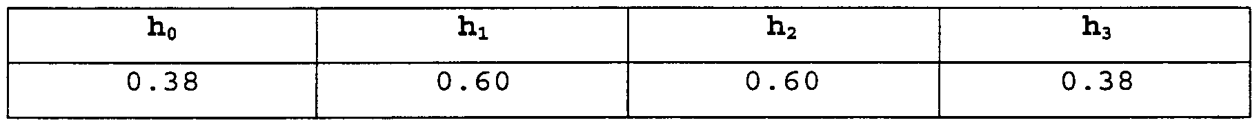
- FIG. 5b represents the results of tests with a fixed radioelectric channel, that is to say a channel comprising filter coefficients h 0 , hi, h 2 and h 3 of fixed value. These coefficients had the values given below in Table 1:
- the pure decoding curve in dashed line, corresponds to the performance of the convolutional code chosen in Gaussian noise.
- the results obtained are shown in solid lines for the implementation of the process which is the subject of the present invention.
- the degradation introduced compared to the case of pure decoding seems to be less than the value 4.2 dB and results from the interaction between the trellis of the channel, internal code, and trellis of the coding, external code.
- the process which is the subject of the present invention makes it possible to obtain a result close to the optimal solution represented by points in FIG. 5b, the axis abscissas being graduated in decibel dB and the ordinate axis in bit error rate BER.
- Figures 5c to 5h represent the error rate of frames on the ordinate FER, with respect to the level in decibels on the abscissa. Indeed, for systems of the type
- FIG. 5c the case of a typical Urban type GSM mobile radio channel has been shown for a useful bit rate at 2 Mbit / s.
- the filter coefficients representative of the radio transmission channel follow a complex Gaussian distribution, their temporal variation being given by a normalized Doppler profile.
- the Typical Urban type channel represented in FIG. 5c corresponds to an urban macrocell type situation for which the speed at 2 Mbit / s corresponds well to the evolution of mobile services towards multimedia.
- the values of the filter coefficients are given in table 2 for the corresponding radio channel: TABLE 2
- the different types of channels corresponding to the aforementioned model are more or less easy to equalize according to their fading statistics and their RMS delay.
- the model D represented in FIG. 5g is the only one to contain a Rice-type fainting, this model being easy to equalize.
- the E model is the most difficult to equalize, since its RMS delay reaches 250 ns and requires a learning sequence allowing the channel to be estimated over a duration of nearly 50 symbols.
- the radioelectric parameters of model A represented in figure 5d are given in table 3 below: TABLE 3
Landscapes
- Engineering & Computer Science (AREA)
- Computer Networks & Wireless Communication (AREA)
- Signal Processing (AREA)
- Power Engineering (AREA)
- Artificial Intelligence (AREA)
- Error Detection And Correction (AREA)
Abstract
Description
Procédé de décodage et d'égalisation conjointe d'un signal numérique protégé par un code défini par un treillisMethod for decoding and joint equalization of a digital signal protected by a code defined by a trellis
L'invention concerne un procédé de décodage et d'égalisation conjointe d'un signal numérique protégé par un code défini par un treillis.The invention relates to a method of decoding and joint equalization of a digital signal protected by a code defined by a trellis.
Avec 1 ' avènement et le développement récents de l'échange d'informations par l'intermédiaire de messages numériques, la transmission fiable et performante de données numériques est devenue un enjeu économique.With the advent and recent development of the exchange of information via digital messages, the reliable and efficient transmission of digital data has become an economic issue.
Parmi les modes de transmission utilisés, la transmission numérique par paquets occupe une place prééminente, en raison de la flexibilité et de la fiabilité des protocoles de transmission de ces données. Toutefois, le développement de transmissions à très haut débit sur canaux radioélectriques, présentant des caractéristiques de sélectivité en fréquence variables dans le temps, rend nécessaire de soumettre les données numériques, constitutives de ces messages et support de ces informations, à un processus de protection par codage spécifique. Ces processus de protection ont pour objet d'introduire dans les données numériques une certaine redondance, laquelle, en présence de dégradation de ces données du fait de la transmission, permet, dans certaines conditions, de reconstituer le signal d'origine. A titre d'exemple non limitatif, on peut citer la protection de données numériques par un code convolutif de rendement R = k/n où le rendement k/n est représentatif de la redondance introduite, et la transmission ATM (Asynchronous Transmission Mode) sur un lien radio, avec granularité au niveau des cellules ATM. On rappelle que la notion de granularité implique la possibilité de transmission de chaque cellule ATM isolée, sans entrelacement des cellules.Among the transmission modes used, digital packet transmission occupies a prominent place, due to the flexibility and reliability of the protocols for transmitting this data. However, the development of very high speed transmissions on radio channels, having frequency selectivity characteristics that vary over time, makes it necessary to subject the digital data, constituting these messages and medium of this information, to a process of protection by specific coding. The purpose of these protection processes is to introduce into the digital data a certain redundancy, which, in the presence of degradation of this data due to the transmission, makes it possible, under certain conditions, to reconstruct the original signal. By way of nonlimiting example, one can cite the protection of digital data by a convolutional code of yield R = k / n where the yield k / n is representative of the redundancy introduced, and ATM transmission (Asynchronous Transmission Mode) on a radio link, with granularity at the level of the ATM cells. Remember that the notion of granularity implies the possibility of transmission of each isolated ATM cell, without cell interleaving.
En raison de la nature physique du canal radioélectrique, la transmission de données numériques s'effectue en présence de trajets multiples de propagation. La réception et le décodage de ces messages nécessitent en conséquence une égalisation du signal reçu. La complexité des traitements d'égalisation augmente très rapidement avec la dispersion des retards, et, également, avec le débit des symboles transmis. C'est en particulier le cas en milieu urbain, lors de la transmission de signaux et messages de radiotéléphonie mobile.Due to the physical nature of the radio channel, digital data transmission takes place in the presence of multiple propagation paths. The reception and decoding of these messages therefore require equalization of the received signal. The complexity of the equalization treatments increases very rapidly with the dispersion of the delays, and also with the speed of the symbols transmitted. This is particularly the case in urban areas, during the transmission of signals and messages of mobile radiotelephony.
La protection introduite par codage de ces données numériques transmises permet de remédier partiellement aux erreurs introduites. Toutefois, l'égalisation rendue nécessaire par les interférences sur les symboles, dues aux trajets multiples, n'est jamais parfaite et il est alors nécessaire de disperser le plus possible les bouffées d'erreurs en sortie de l'égaliseur, afin que le décodeur canal puisse fonctionner sur un signal à densité d'erreur sensiblement constante plus réduite.The protection introduced by coding these transmitted digital data partially remedies the errors introduced. However, the equalization made necessary by the interference on the symbols, due to the multiple paths, is never perfect and it is then necessary to disperse the bursts of errors as much as possible at the output of the equalizer, so that the decoder channel can operate on a signal with a substantially constant error density which is lower.
Un tel mode opératoire peut être obtenu par un processus d'entrelacement des données codées, ce qui interdit la notion de granularité, et qui, en outre, introduit un retard que l'on cherche nécessairement à minimiser, ce qui a priori apparaît contradictoire.Such a mode of operation can be obtained by an interleaving process of the coded data, which prohibits the notion of granularity, and which, moreover, introduces a delay which one necessarily seeks to minimize, which a priori appears contradictory.
De plus, pour de hauts débits, la taille de l'entrelacement devient prohibitive. D'autre part, la présence d'un décodeur de canal en aval du dispositif d'égalisation, le séquencement égalisation/décodage étant rendu nécessaire par le séquencement codage/transmission/trajets multiples à l'émission, incite à mettre en œuvre un processus d'égalisation donnant des symboles égalisés souples, c'est-à-dire dont la valeur ferme est assortie d'une valeur de probabilité de vraisemblance, ce qui augmente d'autant la complexité de l'égalisation et du traitement global .In addition, for high speeds, the size of the interleaving becomes prohibitive. On the other hand, the presence of a channel decoder downstream of the equalization device, the sequencing equalization / decoding being made necessary by coding / transmission / multipath sequencing on transmission, incites to implement an equalization process giving flexible equalized symbols, that is to say whose firm value is matched by 'a likelihood probability value, which increases the complexity of equalization and overall processing accordingly.
La présente invention a pour objet de remédier aux inconvénients des procédés de l'art antérieur précédemment cités .The object of the present invention is to remedy the drawbacks of the methods of the prior art mentioned above.
Un objet de la présente invention est en conséquence la mise en œuvre d'un procédé permettant d'effectuer conjointement les opérations d'égalisation et de décodage de canal directement sur le treillis du décodeur canal, treillis dont la complexité est fixe et indépendante de la longueur de la réponse impulsionnelle du canal .An object of the present invention is therefore the implementation of a method making it possible to carry out jointly the operations of channel equalization and decoding directly on the trellis of the channel decoder, trellis whose complexity is fixed and independent of the length of the channel impulse response.
Un autre objet de la présente invention est la mise en œuvre d'un procédé permettant d'effectuer conjointement les opérations d'égalisation et de décodage de canal de données numériques transmises sous forme de paquets, la réponse impulsionnelle du canal étant supposée constante pendant la transmission d'un paquet. Un autre objet de la présente invention est la mise en œuvre d'un procédé permettant d'effectuer conjointement les opérations d'égalisation et de décodage de canal de données numériques transmises par paquets, en l'absence d'entrelacement sur plusieurs paquets, ce mode opératoire étant particulièrement adapté aux systèmes de transmission haut débit qui doivent assurer une granularité au niveau paquet, tels que les systèmes ATM sur liaison radio.Another object of the present invention is the implementation of a method making it possible to carry out jointly the operations of equalization and decoding of channel of digital data transmitted in the form of packets, the impulse response of the channel being assumed to be constant during the transmission of a packet. Another object of the present invention is the implementation of a method making it possible to jointly perform the equalization and channel decoding operations of digital data transmitted in packets, in the absence of interleaving on several packets, this operating mode being particularly suitable for high speed transmission systems which must ensure granularity at the packet level, such as over-the-air ATM systems.
Un autre objet de la présente invention est la mise en œuvre d'un procédé permettant d'effectuer conjointement les opérations d'égalisation et de décodage de canal supprimant la nécessité d'une égalisation à sortie souple, du fait du caractère conjoint des opérations d'égalisation et de décodage de canal.Another object of the present invention is the implementation of a method making it possible to jointly perform the equalization and channel decoding operations eliminating the need for equalization at flexible output, due to the joint nature of the operations of equalization and channel decoding.
Un autre objet de la présente invention est la mise en œuvre d'un procédé permettant d'effectuer conjointement les opérations d'égalisation et de décodage de canal particulièrement adapté au traitement d'une modulation à grand nombre d'états, ce qui permet de s'affranchir de l'augmentation significative de la complexité d'un processus au sens du maximum de vraisemblance de type classique.Another object of the present invention is the implementation of a method making it possible to carry out jointly the equalization and channel decoding operations particularly suitable for processing a modulation with a large number of states, which makes it possible to get rid of the significant increase in the complexity of a process in the sense of maximum likelihood of the classic type.
Un autre objet de la présente invention est enfin la mise en œuvre d'un procédé permettant d'effectuer conjointement les opérations d'égalisation et de décodage de canal permettant d'éviter le phénomène de propagation d'erreurs lors du décodage, par mise en œuvre d'une version adaptée de l'algorithme de Viterbi.Another object of the present invention is finally the implementation of a method making it possible to carry out jointly the operations of channel equalization and decoding making it possible to avoid the phenomenon of propagation of errors during decoding, by implementing work of an adapted version of the Viterbi algorithm.
Le procédé de décodage et d'égalisation conjointe d'un signal numérique protégé par un code défini par un treillis, objet de la présente invention, s'applique à un signal transmis par paquets non entrelacés . Chaque paquet comporte une séquence connue et une séquence de données codées, à chaque suite de bits x = {xn} , de bit courant xn, soumise au processus de codage défini par un treillis et à un processus de modulation, correspondant une suite de symboles y = {yn} de symbole courant yn vérifiant la relation yn = f (xn;xn-ι; —,Xn-κ) • La suite de bits antérieurs au bit courant, en-ι (x) = {xn-ι;xn-2;-;Xn-κ} représente l'état du processus de codage à l'état antérieur n-1 et le symbole courant yn de la suite de symboles vérifie la relation yn = f (xn, en-ι (x) ) . Cette suite de symboles est soumise de fait à un filtrage transverse de réponse impulsionnelle finie de coefficients de filtrage {h0 ; hi ; ...; hL} représentatifs du canal radioélectrique pour engendrer une suite de symboles observés r = {rn} . Chaque symbole observé rn vérifie la relation rn = zn+bn où zn désigne un symbole courant en sortie du canal et bn un bruit résiduel affectant ce dernier. Chaque symbole courant en sortie du canal courant zn vérifie la relation : zn = g (yn_yn-ι;...;yn-ι_)The method of decoding and joint equalization of a digital signal protected by a code defined by a trellis, object of the present invention, applies to a signal transmitted in non-interleaved packets. Each packet comprises a known sequence and a sequence of coded data, at each sequence of bits x = {x n }, of current bit x n , subjected to the coding process defined by a trellis and to a modulation process, corresponding to a sequence of symbols y = {y n } of current symbol y n checking the relation y n = f (x n ; x n -ι; -, Xn-κ) • The sequence of bits prior to the current bit, e n -ι (x) = {x n -ι; x n -2; - ; Xn-κ} represents the state of the coding process in the previous state n-1 and the current symbol y n of the symbol sequence checks the relation y n = f (x n , e n -ι (x) ). This series of symbols is subjected in fact to a transverse filtering of finite impulse response of filtering coefficients {h 0 ; hi; ...; h L } representative of the radio channel to generate a series of observed symbols r = {r n }. Each observed symbol r n checks the relation r n = z n + b n where z n denotes a current symbol at the output of the channel and b n a residual noise affecting the latter. Each current symbol at the output of the current channel z n checks the relationship: z n = g (yn_yn-ι; ...; yn-ι_)
= h0yn + hιyn-! + ... + hLyn-= h 0 y n + hιy n -! + ... + h L y n -
= φ (xn;Xn-ι;.»;Xn-L-κ) • Ce procédé consiste à estimer chaque bit courant xn de la suite de bits x= {xn} au sens du maximum de vraisemblance par minimisation de 1 ' erreur quadratique entre symbole observé et symbole courant en sortie du canal= φ (x n ; Xn-ι;. "; Xn-L-κ) • This process consists in estimating each current bit x n of the bit sequence x = {x n } in the sense of maximum likelihood by minimization of 1 quadratic error between observed symbol and current symbol at the channel output
ε2(x) = ∑|rn -z„ =∑|rn -φ(xn;xn.,;...;xn._.κ)|2 ,ε 2 (x) = ∑ | r n -z „= ∑ | r n -φ (x n ; x n. ,; ...; x n. _. κ ) | 2 ,
II est remarquable en ce que, pour tout symbole courant en sortie du canal zn issu de la transmission, du fait de trajets multiples, la suite successive des symboles {yn-ι_;yn-L+ι;yn-ι;yn} émise par le processus de codage pour la suite de bits x = {xn} correspondant à des états successifs en-L(x); en.L+ι (x) ;...;en-ι (x) et finalement en(x), qui définissent des branches entre nœuds d'états successifs, une succession de branches dessinant un chemin d'un treillis représentant ce code, ce procédé consiste en outre à calculer l'erreur quadratique à partir de l'ensemble des symboles observés et des branches d'états successifs du processus de codage, en fonction de la métrique de branche de la dernière transition en-ι(x)—» en(x) du processus de codage, selon la relation :It is remarkable in that, for any current symbol at the output of the channel z n resulting from the transmission, due to multiple paths, the successive sequence of the symbols {yn-ι_; yn-L + ι; yn-ι; yn} issued by the coding process for the bit sequence x = {x n } corresponding to successive states e nL (x); e n . L + ι (x); ...; e n -ι (x) and finally e n (x), which define branches between nodes of successive states, a succession of branches drawing a path of a trellis representing this code, this method also consists in calculating the quadratic error from the set of observed symbols and branches of successive states of the coding process, as a function of the branch metric of the last transition e n -ι (x) - »e n (x) of the coding process, according to the relation:
![]()
![]()
Cette métrique de branche est calculée par remontée des états successifs au niveau de chaque nœud d'état sur une longueur égale à la mémoire du canal, et à inhiber, au cours de cette remontée, le processus de propagation d'erreur du fait du calcul des métriques de branche, par mémorisation au niveau de chaque nœud i et à chaque instant d'un nombre S > 1 de survivants, chaque survivant étant défini par une métrique accumulée M(i,t,k) pour le nœud i à 1 ' instant t pour le survivant de rang k considéré k e [1,S] , et par une mise à jour de chaque survivant à l'instant t+1 pour chaque nœud par calcul d'une métrique de branche et sélection des S meilleures métriques de branche parmi 1 ' ensemble des métriques de branche possibles au nœud considéré. Le survivant final est déterminé comme le survivant de plus petite métrique, Mm(0,τ,l), et la séquence de bits d'information correspondante est lue par remontée des nœuds d'état successifs . Le procédé, objet de la présente invention, trouve application à tout système de transmission ATM sur lien radio, avec granularité.This branch metric is calculated by raising the successive states at each state node over a length equal to the memory of the channel, and to inhibit, during this rise, the error propagation process due to the calculation branch metrics, by memorization at the level of each node i and at each instant of a number S> 1 of survivors, each survivor being defined by an accumulated metric M (i, t, k) for the node i at 1 ' instant t for the survivor of rank k considered ke [1, S], and by updating each survivor at time t + 1 for each node by calculating a branch metric and selecting the best S metrics of branch among the set of possible branch metrics at the node considered. The final survivor is determined as the survivor of smaller metric, M m (0, τ, l), and the corresponding sequence of information bits is read by raising the successive state nodes. The method which is the subject of the present invention finds application to any ATM transmission system over a radio link, with granularity.
Il sera mieux compris à la lecture de la description et à l'observation des dessins ci-après, dans lesquels, outre la figure 1 relative à l'art antérieur, la figure 2a représente un schéma synoptique d'un processus de codage et de transmission permettant de définir le contexte de mise en œuvre du procédé de décodage et d'égalisation conjointe d'un signal numérique protégé par un code défini par un treillis, conforme à l'objet de la présente invention ;It will be better understood on reading the description and on observing the drawings below, in which, in addition to FIG. 1 relating to the prior art, FIG. 2a represents a block diagram of a coding and transmission making it possible to define the context for implementing the method of decoding and joint equalization of a digital signal protected by a code defined by a trellis, in accordance with the object of the present invention;
- la figure 2b représente à titre d'exemple illustratif un organigramme représentatif du procédé de codage et d'égalisation conjointe d'un signal numérique protégé par un code défini par un treillis, conforme à l'objet de la présente invention ;- Figure 2b shows by way of illustrative example a flowchart representative of the coding and joint equalization process of a digital signal protected by a code defined by a trellis, in accordance with the object of the present invention;
- la figure 3a représente à titre illustratif un chemin du treillis codeur, en trait plein, et la suite des symboles zn correspondant à ce chemin ;- Figure 3a shows by way of illustration a path of the coding trellis, in solid lines, and the series of symbols z n corresponding to this path;
- les figures 3b et 3c représentent un schéma illustratif de calcul des S meilleures métriques à chaque nœud du treillis représenté en figure 3a ;- Figures 3b and 3c show an illustrative diagram of calculation of the S best metrics at each node of the trellis shown in Figure 3a;
- la figure 4 représente un organigramme d'une variante de mise en œuvre du procédé objet de l'invention tel que représenté en figure 2b ;- Figure 4 shows a flowchart of an alternative implementation of the method of the invention as shown in Figure 2b;
- la figure 5a représente un schéma synoptique d'un mode opératoire utilisé pour effectuer des essais de simulation de mise en œuvre du procédé objet de la présente invention ; - les figures 5b et 5c représentent différents essais comparatifs de valeurs de taux d'erreur de paquets obtenues grâce à la mise en œuvre du procédé objet de la présente invention et à une solution optimale par décodage puis égalisation.- Figure 5a shows a block diagram of an operating mode used to carry out simulation tests of implementation of the method object of the present invention; FIGS. 5b and 5c represent different comparative tests of packet error rate values obtained thanks to the implementation of the method which is the subject of the present invention and to an optimal solution by decoding then equalization.
Préalablement à la description proprement dite du procédé de décodage et d'égalisation conjointe d'un signal numérique protégé par un code défini par un treillis, objet de la présente invention, des rappels relatifs à l'état de la technique et à l'état actuel des connaissances seront donnés ci-après.Prior to the actual description of the process of decoding and joint equalization of a digital signal protected by a code defined by a trellis, object of the present invention, reminders relating to the state of the art and to the state current knowledge will be given below.
Les systèmes de transmission d'informations, tels que les systèmes radiomobiles récents à accès multiples par répartition temporelle, transmettent les données sous forme de paquets de bits préalablement codés. A 1 ' intérieur de ces paquets de bits est introduite une séquence dite d'apprentissage qui permet d'obtenir une bonne estimation du canal, incluant les filtres d'émission et de réception. La forme des paquets retenus dans le cadre de l'illustration de la mise en œuvre du procédé, objet de la présente invention, est donnée ci-après en référence à la figure 1 relative à l'art antérieur. Les séquences de bits constitutives des séquences d'apprentissage peuvent par exemple être des séquences de Cazac choisies pour leurs propriétés d'auto-corrélation.Information transmission systems, such as recent time division multiple access radio mobile systems, transmit data in the form of previously encoded bit packets. Inside these bit packets is introduced a so-called learning sequence which makes it possible to obtain a good estimate of the channel, including the transmission and reception filters. The shape of the packets used in the context of the illustration of the implementation of the method which is the subject of the present invention is given below with reference to FIG. 1 relating to the prior art. The bit sequences constituting the training sequences can for example be Cazac sequences chosen for their auto-correlation properties.
Le canal de transmission introduit ainsi des distorsions à la réception, ces distorsions étant appelées interférences entre symboles. Dans les solutions connues de l'art antérieur, il est nécessaire de mettre en œuvre un égaliseur afin de réduire ou tenter de supprimer les distorsions précitées. Les fonctions d'égalisation et de décodage sont séparées dans les dispositifs de l'art antérieur précités .The transmission channel thus introduces distortions on reception, these distortions being called interference between symbols. In the solutions known from the prior art, it is necessary to implement an equalizer in order to reduce or attempt to eliminate the abovementioned distortions. Equalization and decoding are separated in the aforementioned prior art devices.
Le contexte de génération des suites de bits dans le cadre du processus d'émission des systèmes radiomobiles précités est illustré maintenant en liaison avec la figure 2a.The context of generation of the bit strings in the context of the emission process of the aforementioned mobile radio systems is now illustrated in connection with FIG. 2a.
D'une manière générale, on indique que le procédé, objet de la présente invention, s'applique à un signal numérique tel que représenté en figure 1, ce signal numérique étant protégé par un code défini par un treillis. On rappelle, ainsi, que la notion de code défini par un treillis recouvre les processus de codage convolutif, le codage de type TCM et le codage en blocs par exemple, de manière non limitative. D'une manière plus spécifique, le signal est transmis sur le canal radioélectrique selon une transmission par paquets non entrelacés, chacun des paquets correspondant à la structure de données telle que représentée en figure 1. En référence à la figure 2a, on indique que chaque suite de bits x = {xn}/ de bit courant xn, est ainsi soumise au processus de codage défini par un treillis et à un processus de modulation auquel correspond une suite de symboles y = {yn} , le symbole courant étant désigné par yn. Ainsi, chaque symbole courant vérifie la relation :In general, it is indicated that the method, object of the present invention, applies to a digital signal as shown in FIG. 1, this digital signal being protected by a code defined by a trellis. It is thus recalled that the concept of code defined by a trellis covers the convolutional coding processes, TCM type coding and block coding for example, in a nonlimiting manner. More specifically, the signal is transmitted on the radio channel according to a transmission in non-interleaved packets, each of the packets corresponding to the data structure as represented in FIG. 1. With reference to FIG. 2a, it is indicated that each sequence of bits x = {x n } / of current bit x n , is thus subjected to the coding process defined by a trellis and to a modulation process to which corresponds a series of symbols y = {y n }, the current symbol being designated by y n . Thus, each current symbol checks the relationship:
yn = f (xn;Xn-ι; —;Xn-κ)y n = f (x n ; Xn-ι; -; Xn-κ)
Dans la relation précédente, on indique que f désigne une fonction de codage de profondeur K tenant compte du processus de modulation. La suite de bits antérieurs au bit courant xn, suite de bits désignée par en-ι (x) , vérifie la relation :In the previous relation, it is indicated that f denotes a depth coding function K taking account of the modulation process. The series of bits prior to the current bit x n , the series of bits designated by e n -ι (x), checks the relation:
en-ι (x) = { n-ι; n-2 ,*•••; χn-κ)e n -ι (x) = { n -ι; n- 2 , * •••; χ n-κ)
et représente l'état du processus de codage à l'état antérieur n-1. Le symbole courant yn de la suite de symboles vérifie alors la relation (1) :and represents the state of the coding process in the prior state n-1. The current symbol y n of the symbol sequence then checks the relation (1):
yn = f (xn,en-ι(x) ) (1)y n = f (x n , e n -ι (x)) (1)
En raison de la présence d'un canal de transmission à trajets multiples, la suite de symboles y est de fait soumise à un processus équivalent à un filtrage transverse de réponse impulsionnelle finie pour lequel les coefficients de filtrage peuvent être définis par {h0;hι,-...;h } . Ces coefficients de filtrage sont représentatifs du canal radioélectrique de transmission.Due to the presence of a multipath transmission channel, the symbol sequence there is in fact subjected to a process equivalent to a transverse filtering of finite impulse response for which the filtering coefficients can be defined by {h 0 ; hι, -...; h}. These filter coefficients are representative of the transmission radio channel.
Ainsi que représenté en figure 2a, la succession de l'opération de codage/modulation puis de transmission par le canal à trajets multiples permet d'engendrer une suite de symboles observés notée r = {rn}, chaque symbole observé correspondant en fait à un symbole courant en sortie de canal, noté zn, auquel un bruit résiduel bn est ajouté, ce bruit résiduel affectant chacun des symboles courant en sortie de canal précité. Le bruit résiduel est un bruit blanc Gaussien centré.As shown in FIG. 2a, the succession of the coding / modulation operation then of transmission by the multipath channel makes it possible to generate a series of observed symbols denoted r = {r n }, each observed symbol corresponding in fact to a current symbol at the channel output, denoted z n , to which a residual noise b n is added, this residual noise affecting each of the symbols current at the above-mentioned channel output. Residual noise is centered white Gaussian noise.
Ainsi, chaque symbole observé rn vérifie la relation : Rn = zn + bn Chaque symbole courant en sortie du canal vérifie la relation (2 ) :Thus, each symbol observed r n verifies the relation: R n = z n + b n Each current symbol at the output of the channel checks the relation (2):
zn = g ( yn . yn- _ ; -« ; yn-L) = h0yn + hιyn-ι + ... + hLyn- L ( 2 )z n = g (yn. yn- _; - "; yn-L) = h 0 y n + hιy n -ι + ... + h L y n- L (2)
= φ (xn ; xn-ι ; -.. ; Xn-L-κ)= φ (x n ; x n -ι; - ..; Xn-L-κ)
Selon un aspect remarquable du procédé, objet de la présente invention, en référence à la figure 2a, on indique que le processus de codage/modulation et le processus de transmission par le canal à trajets multiples sont assimilés à une mise en cascade d'un code externe et d'un code interne, la fonction de code interne étant remplie par le canal de transmission à trajets multiples. Ainsi, les codes interne et externe sont respectivement constitués par un dispositif à mémoire qu'on peut représenter par un treillis. A l'ensemble, codeur canal + canal de transmission, correspond un treillis "global", appelé super-treillis, dont le nombre d'états est égal au produit du nombre d'états des deux treillis élémentaires, c'est-à-dire un nombre d'états égal à 2L+K pour une modulation BPSK et un code de rendement 1/n. Le procédé objet de la présente invention est remarquable en ce qu'il utilise seulement le treillis du codeur canal, dont le nombre d'états est indépendant du nombre d'états de la modulation et de la longueur L du canal .According to a remarkable aspect of the method, object of the present invention, with reference to FIG. 2a, it is indicated that the coding / modulation process and the transmission process by the multipath channel are assimilated to a cascading of a external code and an internal code, the internal code function being fulfilled by the multipath transmission channel. Thus, the internal and external codes are respectively constituted by a memory device which can be represented by a trellis. The set, channel encoder + transmission channel, corresponds to a "global" lattice, called super-lattice, the number of states of which is equal to the product of the number of states of the two elementary lattices, that is to say say a number of states equal to 2 L + K for a BPSK modulation and a 1 / n efficiency code. The method which is the subject of the present invention is remarkable in that it uses only the trellis of the channel coder, the number of states of which is independent of the number of modulation states and of the length L of the channel.
Alors que la complexité du treillis du code interne, c'est-à-dire du treillis engendré par le canal à trajets multiples croît de façon exponentielle avec le nombre d'états de la modulation et la longueur du canal en temps symbole, le simple décodage du super-treillis ainsi constitué est rendu prohibitif en complexité pour les transmissions à haut débit .While the complexity of the trellis of the internal code, that is to say of the trellis generated by the multipath channel increases exponentially with the number of modulation states and the length of the channel in symbol time, the simple decoding the super-lattice as well constituted is made prohibitive in complexity for broadband transmissions.
Dans les solutions les plus simples, la réduction du super-treillis est ramenée au seul treillis de codage externe, la métrique de branche étant alors calculée à la manière d'un processus de DFSE, pour Décision Feedback Séquence Estimation, par remontée des nœuds du treillis ainsi simplifié. Toutefois, un tel processus n'apparaît pas suffisamment efficace car il présente l'inconvénient d'un phénomène de propagation d'erreurs lors de la remontée des nœuds successive, erreurs inhérentes au processus DFSE précité.In the simplest solutions, the reduction of the super-lattice is reduced to the single external coding lattice, the branch metric then being calculated in the manner of a DFSE process, for Decision Feedback Sequence Estimation, by raising the nodes of the thus simplified trellis. However, such a process does not appear to be sufficiently effective because it has the drawback of an error propagation phenomenon during the ascent of the successive nodes, errors inherent in the above-mentioned DFSE process.
Le procédé, objet de la présente invention, a pour objet de remédier aux inconvénients de la technique antérieure précitée par la détermination de la réception optimale à partir du super-treillis et par la mise en œuvre d'une technique de décodage de Viterbi généralisée, plus communément désignée par décodage GVA, pour Generalized Vi terbi Algori thm. Pour une description plus détaillée de ce processus de décodage GVA, on pourra utilement se reporter à l'article publié par T.HASHIMOTO, intitulé A List - Type Reduced-Constraint Generalization of the Vi terbi Algori thm, IEEE Transactions on Information Theory, Vol.IT-33, No. 6, Nov.1987.The object of the present invention is to remedy the drawbacks of the aforementioned prior art by determining the optimal reception from the super-lattice and by implementing a generalized Viterbi decoding technique, more commonly known by GVA decoding, for Generalized Vi terbi Algori thm. For a more detailed description of this GVA decoding process, one can usefully refer to the article published by T. HASHIMOTO, entitled A List - Type Reduced-Constraint Generalization of the Vi terbi Algori thm, IEEE Transactions on Information Theory, Vol .IT-33, No. 6, Nov. 1987.
Ainsi, conformément à un aspect particulièrement remarquable du procédé, objet de la présente invention, celui-ci consiste à estimer chaque bit courant xn de la suite de bits x = {xn} au sens du maximum de vraisemblance par minimisation de 1 ' erreur quadratique entre symbole observé et symbole courant en sortie du canal zn. Sur la figure 2b, on a représenté, pour améliorer la compréhension de la mise en œuvre du procédé, objet de la présente invention, l'étape de codage représentée à l'étape 1000 à partir de la suite de bits x, suivie d'une étape 1001 correspondant à la transmission à trajets multiples pour engendrer la suite de symboles observés r = {rn} et la suite de symboles courants en sortie du canal z = {zn} .Thus, in accordance with a particularly remarkable aspect of the method, object of the present invention, it consists in estimating each current bit x n of the series of bits x = {x n } in the sense of maximum likelihood by minimizing 1 ' quadratic error between observed symbol and current symbol at the output of channel z n . In FIG. 2b, in order to improve the understanding of the implementation of the method which is the subject of the present invention, the coding step represented in step 1000 from the sequence of bits x, followed by a step 1001 corresponding to the multipath transmission to generate the series of symbols observed r = {r n } and the series of current symbols at the output of the channel z = {z n }.
L'étape 1001 est alors suivie d'une étape 1002 permettant d'initier l'estimation de xn par la minimisation de l'erreur quadratique vérifiant la relation : ε2(x) = yir -z I
![]()
![]()
En référence à la figure 3a, on indique que pour tout symbole courant en sortie du canal zn issu de la transmission par trajets multiples, la suite successive des symboles yn-L;yn- +ι;-;y étant émise par le processus de codage pour la suite de bits précitée, le processus de codage/modulation et de transmission correspond à des états successifs en.L(x) ;en-ι_+i(x) ; —;en-i(x) et finalement en(X) , ces états successifs correspondant à des branches entre nœuds d'états successifs ainsi que représenté sur la figure 3a précitée. L'estimation des bits successifs xn au sens du maximum de vraisemblance, conformément au procédé objet de la présente invention, conduit alors à chercher la suite de bits {xn} qui minimise l'erreur quadratique exprimée précédemment . Conformément au procédé, objet de la présente invention, cette erreur quadratique peut être exprimée en tenant compte des relations précédentes sous la forme de la relation (3) :With reference to FIG. 3a, it is indicated that for any current symbol at the output of the channel z n resulting from the multipath transmission, the successive sequence of symbols y n - L ; y n - + ι; -; y being emitted by the coding process for the aforementioned bit sequence, the coding / modulation and transmission process corresponds to successive states e n . L (x); e n -ι_ + i (x); -; e n -i (x) and finally e n ( X ), these successive states corresponding to branches between nodes of successive states as shown in FIG. 3a above. The estimation of the successive bits x n in the sense of maximum likelihood, in accordance with the method which is the subject of the present invention, then leads to searching for the series of bits {x n } which minimizes the quadratic error expressed previously. In accordance with the method which is the subject of the present invention, this quadratic error can be expressed by taking account of the preceding relations in the form of the relation (3):
ε20)
![]()
![]()
![]()
![]()
Dans la relation (3) précédente, le terme r -<∑hkyπ_. I peutIn the previous relation (3), the term r - <∑h k y π _. I can
être mis sous la forme :be in the form:
r.-{h0f(x.;e..1(x))+h1f(x..1;e..2(x))+...+ hlf(x_.l;e_.t(x))}.r .- {h 0 f (x.; e .. 1 (x)) + h 1 f (x .. 1 ; e.. 2 (x)) + ... + h l f (x_. l ; e_ .t (x))}.
Le terme entre accolades de la relation précédente correspond à la réponse du filtre transverse représentatif du canal de transmission à trajets multiples soumis à la suite des symboles à la suite du processus de codage/modulation sur une longueur L correspondant à la mémoire du canal, cette suite de symboles s ' écrivant yn-L yn-+ι,...,yn-i yn- Cette suite est émise par le codeur à t = n dans l'hypothèse d'une suite de bits x = {xn} . Dans ces conditions, le codeur passe alors par les états en-L(x) , en-L+ι (x) ,-, en-ι(x) pour aboutir dans l'état en(x). Le symbole courant en sortie du canal lors de la dernière transition est alors égal à zn = ∑h.yo_k . La relation (4 ) ci-après :The term between braces in the previous relationship corresponds to the response of the transverse filter representative of the multipath transmission channel submitted following the symbols following the coding / modulation process over a length L corresponding to the memory of the channel, this sequence of symbols writing y n -L yn- + ι, ..., yn-i yn- This sequence is issued by the coder at t = n assuming a sequence of bits x = {x n }. Under these conditions, the encoder then goes through the states e n - L (x), e n - L + ι (x), -, e n -ι (x) to reach the state e n (x). The current symbol at the output of the channel during the last transition is then equal to z n = ∑hy o _ k . The relation (4) below:
-j ∑h„y_-k [ = r- -h0yπ -j ∑hkyn l ( 4 ) k_o J L k≥l J-j ∑ h „y_- k [= r- -h 0 y π -j ∑h k y n l (4) k _o JL k ≥l J
définit ainsi la métrique de branche de la dernière transition en_ι(x)—_• en(x) et peut être calculée à la manière d'un processus DFSE en remontant les états successifs visités précédemment. Cette métrique dépend du chemin suivi dans le treillis pour arriver dans un état en(x) donné. Ce mode de calcul de la métrique contient intrinsèquement le problème de propagation d'erreur précédemment mentionné dans la description.thus defines the branch metric of the last transition e n _ ι (x) —_ • e n (x) and can be calculated in the manner of a DFSE process by going up the successive states visited previously. This metric depends on the path followed in the trellis to arrive in a given state e n (x). This method of calculating the metric intrinsically contains the problem of error propagation previously mentioned in the description.
Pour cette raison, et dans le but de rendre robuste et efficace le procédé de décodage et d'égalisation conjointe, objet de la présente invention, celui-ci consiste en outre, à l'étape 1003 représentée en figure 2b, à inhiber au cours de cette remontée le processus de propagation d'erreur du fait du calcul des métriques de branche, cette inhibition étant réalisée par mémorisation, au niveau de chaque nœud i et à chaque instant t, d'un nombre S supérieur à 1 de survivants, chaque survivant étant défini par une métrique M(i,t,k) pour le nœud i à 1 ' instant t pour le survivant de rang k considéré. Pour S survivants, on rappelle que k e [0,S-1] . Une mise à jour de chaque survivant est alors effectuée à l'instant t+1 pour chaque nœud i par calcul d'une métrique de branche et sélection des S meilleures métriques de branche parmi l'ensemble des 2S métriques de branche possibles au nœud considéré. L'étape 1003 précédemment décrite est alors suivie d'une étape 1004 consistant à déterminer le survivant final de plus petite métrique Mm(0,τ,l) et à lire la séquence de bits d'information correspondante par remontée d'état des nœuds d'états successifs.For this reason, and with the aim of making the decoding and joint equalization method, object of the present invention, robust and efficient, it also consists, in step 1003 shown in FIG. 2b, of being inhibited during from this feedback the error propagation process due to the calculation of the branch metrics, this inhibition being carried out by memorization, at the level of each node i and at each instant t, of a number S greater than 1 of survivors, each survivor being defined by a metric M (i, t, k) for the node i at the instant t for the survivor of rank k considered. For S survivors, we recall that ke [0, S-1]. An update of each survivor is then carried out at time t + 1 for each node i by calculation of a branch metric and selection of the S best branch metrics from all of the 2S possible branch metrics at the node considered . The step 1003 previously described is then followed by a step 1004 consisting in determining the final survivor with the smallest metric M m (0, τ, l) and in reading the corresponding sequence of information bits by reporting the status of the successive state nodes.
On comprend bien sûr que le procédé, objet de la présente invention, peut alors être répété pour toute suite de bits suivante correspondant à un message transmis . Une description plus détaillée du processus d'inhibition de la propagation d'erreurs sera maintenant donnée en liaison avec la figure 3b.It will of course be understood that the method which is the subject of the present invention can then be repeated for any following series of bits corresponding to a transmitted message. A more detailed description of the error propagation inhibition process will now be given in conjunction with Figure 3b.
En référence à la figure 3b précitée, on indique que le processus d'inhibition de propagation d'erreurs consiste à retenir un nombre S > 1 de survivants en chaque nœud de rang i et à chaque instant t. En effet, si le vrai chemin du treillis, celui qui correspond à la séquence de symboles émise, n'est pas le meilleur à un instant donné, il ne doit cependant pas être perdu définitivement. En référence à la figure précitée, on indique que le symbole courant en sortie du canal zπ = ∑hkyn_k .estWith reference to FIG. 3b above, it is indicated that the process of inhibition of propagation of errors consists in retaining a number S> 1 of survivors in each node of rank i and at each instant t. Indeed, if the real path of the trellis, that which corresponds to the sequence of symbols emitted, is not the best at a given moment, it must not however be lost definitively. With reference to the above-mentioned figure, it is indicated that the current symbol at the output of the channel z π = ∑h k y n _ k. Is
obtenu dans l'hypothèse où on arrive à l'état en(x) par la succession d'états en-L (x) , en-L+ι (x) ,..., en-ι (x) , tel que représenté au dessin. Dans l'hypothèse à titre d'exemple non limitatif d'un treillis issu d'un code convolutif de rendement 1/n correspondant donc à un treillis comportant N = 2 états, de chaque nœud partent ainsi deux branches, l'une correspondant à un bit de valeur 0 à l'entrée du codeur, l'autre à un bit 1 à cette même entrée du codeur. A chaque nœud de rang i et à chaque instant t sont stockés S survivants, chaque survivant correspondant à une suite de bits, notée Siιt,k où i désigne le rang du nœud considéré, t l'instant correspondant et k le rang du survivant considéré tel que 0 < k < S-l. Chaque suite de bits constitutive d'un survivant est caractérisée par une longueur appelée métrique accumulée de chemins, notée M(i,t,k), c'est-à-dire métrique du keme survivant au nœud de rang i à l'instant t donné. On rappelle que la notion de métrique correspond à la définition selon laquelle, dans la théorie de la mesure dans un espace donné, la notion de métrique est basée sur la formule de la distance entre deux points de cet espace.obtained on the assumption that we arrive at the state e n (x) by the succession of states e nL (x), e n - L + ι (x), ..., e n -ι (x), as shown in the drawing. In the assumption by way of nonlimiting example of a trellis resulting from a convolutional code of yield 1 / n therefore corresponding to a trellis comprising N = 2 states, from each node thus leave two branches, one corresponding to one bit of value 0 at the encoder input, the other at a bit 1 at this same encoder input. At each node of rank i and at each instant t are stored S survivors, each survivor corresponding to a series of bits, denoted S iιt , k where i denotes the rank of the node considered, t the corresponding instant and k the rank of the survivor considered as 0 <k <Sl. Each sequence of bits constituting a survivor is characterized by a length called accumulated metric of paths, denoted M (i, t, k), that is to say metric of the k th surviving at the node of rank i at instant t given. We recall that the notion of metric corresponds to the definition according to which, in the theory of measurement in a given space, the notion of metric is based on the formula of the distance between two points of this space.
Les valeurs de métrique M(i,t,k) étant connues à un instant t quelconque, leur mise à jour à l'instant t+1 peut être effectuée de la manière ci-après, dans le cas d'un code de rendement 1/n : tout nœud de rang i est consécutif à deux antécédents ou ancêtres, ainsi que représenté en figure 3c, ji et j2, lesquels sont déterminés par leurs ensembles de S survivants respectifs tel que Sji,t,__ et Sj2,t,k avec 0 < k < S-l et de métriques respectives M(jx,t,k) et M(j2,t,k).Il existe ainsi 2S manières possibles d'atteindre un nœud de rang i à l'instant t+1 à raison de S possibilités pour l'ancêtre ji à l'instant t et S possibilités pour l'ancêtre j2 à ce même instant t, chaque ancêtre étant de la forme d'un survivant à l'instant t prolongé d'une branche allant de ji, respectivement j2, vers le nœud de rang i. Pour chacun des 2 x S candidats, la métrique de la dernière branche, c'est-à-dire celle incidente au nœud de rang i, est calculée selon la relation (4) précédente en remontant les chemins survivants en chaque ancêtre ji et j2. Les métriques de branche ainsi obtenues sont notées δm(j,i,k) et l'on obtient ainsi les quantités : M( jx, t,k) + δm(jι, i,k) pour k = 0,...,S-1 M(j2, t,k) + δm(j2,i,k) avec k = 0,...,S-1. Il est ainsi possible de retenir, pour le nœud de rang i à l'instant t+1, les S meilleurs chemins parmi les 2 x S possibles, ce qui permet d'obtenir S survivants pour le nœud de rang i à l'instant t+1.Since the metric values M (i, t, k) are known at any time t, their updating at time t + 1 can be carried out as follows, in the case of a yield code 1 / n: any node of rank i is consecutive to two antecedents or ancestors, as shown in FIG. 3c, ji and j 2 , which are determined by their respective sets of S survivors such as Sji, t , __ and Sj 2 , t, k with 0 <k <Sl and respective metrics M (j x , t, k) and M (j 2 , t, k) .There are 2S possible ways to reach a node of rank i at instant t + 1 at the rate of S possibilities for the ancestor ji at the instant t and S possibilities for the ancestor j 2 at this same instant t, each ancestor being in the form of a survivor at the prolonged instant t from a branch going from ji, respectively j 2 , to the node of rank i. For each of the 2 x S candidates, the metric of the last branch, that is to say the metric incident at the node of rank i, is calculated according to the previous relation (4) by going up the surviving paths in each ancestor ji and j 2 . The branch metrics thus obtained are noted δm (j, i, k) and we thus obtain the quantities: M (jx, t, k) + δm (jι, i, k) for k = 0, ... , S-1 M (j 2 , t, k) + δm (j 2 , i, k) with k = 0, ..., S-1. It is thus possible to retain, for the node of rank i at time t + 1, the S best paths among the 2 x S possible, which makes it possible to obtain S survivors for the node of rank i at time t + 1.
En ce qui concerne la mise en œuvre de l'étape 1004, on indique que celle-ci peut être effectuée lorsqu'on a reçu tous les symboles codés d'un paquet et que les opérations précédentes ont été réalisées, le survivant final de plus petite métrique pouvant alors être déterminé. Il s'agit dans cette hypothèse de la mise en œuvre d'un algorithme de Viterbi selon une version étendue et il est alors possible de remonter le meilleur chemin pour lire la séquence de bits d'information correspondante par une opération de remontée, connue sous le nom de i3ac_ Tracking en langage anglo-saxon. En ce qui concerne le nombre de survivants retenus, on indique que S peut être pris égal à 4, de manière non limitative.With regard to the implementation of step 1004, it is indicated that this can be carried out when all the coded symbols of a packet have been received and that the preceding operations have been carried out, the final survivor moreover small metric that can then be determined. In this hypothesis, it is the implementation of a Viterbi algorithm according to an extended version and it is then possible to go up the best path to read the sequence of bits of corresponding information by an ascent operation, known as the name of i3ac_ Tracking in Anglo-Saxon language. With regard to the number of survivors retained, it is indicated that S can be taken equal to 4, in a nonlimiting manner.
Une description plus détaillée d'un mode opératoire spécifique permettant d'améliorer la fiabilité du procédé, objet de la présente invention, sera maintenant donnée en liaison avec la figure 4. Sur la figure 4, on a représenté le mode opératoire spécifique précité, lequel peut consister, en une étape 2000, à déterminer le second meilleur survivant vis-à-vis du survivant de plus petite métrique, la métrique de ce survivant final adjacent étant notée Mm. (0,τ,l), cette métrique étant voisine et immédiatement supérieure à la plus petite métrique précédemment mentionnée dans la description.A more detailed description of a specific operating mode making it possible to improve the reliability of the process which is the subject of the present invention will now be given in connection with FIG. 4. In FIG. 4, the aforementioned specific operating mode is shown, which may consist, in a step 2000, to determine the second best survivor vis-à-vis the survivor with the smallest metric, the metric of this adjacent final survivor being denoted M m . (0, τ, l), this metric being close to and immediately superior to the smallest metric previously mentioned in the description.
L'étape 2000 peut alors être suivie d'une étapeStep 2000 can then be followed by a step
2001 consistant à calculer un écart de métrique, valeur absolue de la différence de métriques entre la plus petite métrique et la métrique voisine immédiatement supérieure, cet écart de métrique vérifiant la relation :2001 consisting in calculating a metric deviation, absolute value of the metric difference between the smallest metric and the immediately higher neighboring metric, this metric deviation verifying the relation:
![]()
![]()
A titre de simplification, les métriques ont été désignées par Mm pour la métrique la plus petite et Mm. pour la métrique voisine immédiatement supérieure à la plus petite métrique .For simplicity, the metrics have been designated by M m for the smallest metric and M m . for the neighboring metric immediately superior to the smallest metric.
L'écart de métrique est ensuite comparé, en une étape 2002 de test, à une valeur de seuil selon la relation : δM < Se la valeur de seuil Se pouvant être définie à partir de résultats expérimentaux et de conditions d'utilisation.The metric deviation is then compared, in a test step 2002, with a threshold value according to the relationship: δ M <S e the threshold value S e can be defined from experimental results and conditions of use .
Si δm est inférieur au seuil 2002, les deux meilleurs survivants sont trop proches et le choix entre les deux n'est pas fiable. Le paquet est déclaré effacé,If δ m is below the 2002 threshold, the two best survivors are too close and the choice between the two is not reliable. The package is declared deleted,
2004, car les deux décodages sur les deux chemins auraient conduit à des résultats différents.2004, because the two decodings on the two paths would have led to different results.
Dans le cas contraire, δm > seuil, le décodage est présumé correct et le paquet est accepté, 2003. Des simulations ont été réalisées afin de mettre en évidence les performances du procédé, objet de la présente invention, précédemment décrit.Otherwise, δ m > threshold, decoding is assumed to be correct and the packet is accepted, 2003. Simulations were carried out in order to demonstrate the performance of the method, object of the present invention, previously described.
Sur la figure 5a, on a représenté les modes opératoires correspondants dans le cadre d'un schéma synoptique pour la partie canal à partir d'une source binaire Ai, d'un codeur introduisant un codage convolutif A2, d'une modulation de canal de type MDP4 A3, d'une insertion de séquence connue de type CAZAC , et d'un filtrage en racine de Nyquist A5.In FIG. 5a, the corresponding operating modes have been represented in the context of a block diagram for the channel part from a binary source Ai, from an encoder introducing a convolutional coding A 2 , from a channel modulation. of type MDP4 A 3 , of an insertion of known sequence of type CAZAC, and of filtering at the root of Nyquist A 5 .
En ce qui concerne la transmission par le canal radioelectrique multitrajets, celui-ci correspondait à un canal radiomobile Bi suivi de l'addition d'un bruit blanc Gaussien additif (Addi tive Whi te Gaussian Noise) B2. En ce qui concerne la partie réception, celle-ci correspondait à un filtrage en racine de Nyquist Ci, suivi d'une estimation de canal C2 puis d'une égalisation et d'un décodage conjoints, conformes au procédé objet de la présente invention, C3, et d'une décision C4. Les essais de simulation ont été réalisés grâce au logiciel COSSAP, commercialisé par la société SYNOPSYS . Le facteur de roll-off du filtrage en racine de Nyquist a été fixé à 0,25 et le code convolutif utilisé était un code de longueur de contrainte 5, soit un treillis de 16 états. Les polynômes générateurs étaient de la forme :As regards transmission by the multi-path radioelectric channel, this corresponded to a radiomobile channel Bi followed by the addition of an additive white Gaussian noise (Addi tive Whi te Gaussian Noise) B 2 . As regards the reception part, this corresponded to a Nyquist Ci root filtering, followed by a C 2 channel estimation then by joint equalization and decoding, in accordance with the method which is the subject of the present invention , C 3 , and a decision C 4 . The simulation tests were carried out using COSSAP software, marketed by the company SYNOPSYS. The roll-off factor of the Nyquist root filtering was set at 0.25 and the convolutional code used was a constraint length code 5, ie a lattice of 16 states. The generator polynomials were of the form:
Gι(D) = 1+D3+D4 etGι (D) = 1 + D 3 + D 4 and
G2(D) = 1+D+D3+D4 introduisant une distance minimale de 7. La modulation choisie en sortie du code convolutif était une modulation de phase à quatre états tournée de 45° afin d'utiliser les séquences CAZAC.G 2 (D) = 1 + D + D 3 + D 4 introducing a minimum distance of 7. The modulation chosen at the output of the convolutional code was a modulation four-state phase rotated 45 ° to use CAZAC sequences.
La figure 5b représente les résultats d'essais avec un canal radioelectrique fixe, c'est-à-dire un canal comportant des coefficients de filtrage h0, hi, h2 et h3 de valeur fixée. Ces coefficients avaient les valeurs données ci-après dans le tableau 1 :FIG. 5b represents the results of tests with a fixed radioelectric channel, that is to say a channel comprising filter coefficients h 0 , hi, h 2 and h 3 of fixed value. These coefficients had the values given below in Table 1:
TABLEAU 1TABLE 1
Les résultats, comparés avec la solution optimale, sont représentés en figure 5b.The results, compared with the optimal solution, are shown in Figure 5b.
A l'observation de la figure 5b, on peut constater qu'alors que le procédé, objet de la présente invention, est sous-optimal, il donne toutefois des performances proches de la solution optimale pour une complexité abordable, c'est-à-dire S = 4.Upon observation of FIG. 5b, it can be seen that while the method which is the subject of the present invention is sub-optimal, it nevertheless gives performances close to the optimal solution for an affordable complexity, that is to say - say S = 4.
La courbe de décodage pur, en trait mixte, correspond aux performances du code convolutif choisi en bruit Gaussien. Les résultats obtenus sont représentés en trait continu pour la mise en œuvre du procédé, objet de la présente invention. La dégradation introduite par rapport au cas du décodage pur semble être inférieure à la valeur 4,2 dB et résulte de l'interaction entre le treillis du canal, code interne, et treillis du codage, code externe. Le procédé, objet de la présente invention, permet d'obtenir un résultat proche de la solution optimale représentée par points sur la figure 5b, l'axe des abscisses étant gradué en décibel dB et l'axe des ordonnées en taux d'erreur de bit BER.The pure decoding curve, in dashed line, corresponds to the performance of the convolutional code chosen in Gaussian noise. The results obtained are shown in solid lines for the implementation of the process which is the subject of the present invention. The degradation introduced compared to the case of pure decoding seems to be less than the value 4.2 dB and results from the interaction between the trellis of the channel, internal code, and trellis of the coding, external code. The process which is the subject of the present invention makes it possible to obtain a result close to the optimal solution represented by points in FIG. 5b, the axis abscissas being graduated in decibel dB and the ordinate axis in bit error rate BER.
Les figures 5c à 5h représentent le taux d'erreur de trames en ordonnées FER, vis-à-vis du niveau en décibels en abscisses. En effet, pour des systèmes du typeFigures 5c to 5h represent the error rate of frames on the ordinate FER, with respect to the level in decibels on the abscissa. Indeed, for systems of the type
ATM fixe ou radio, seul le taux d'erreur de cellule ou de trame est pertinent.Fixed or radio ATM, only the cell or frame error rate is relevant.
Sur la figure 5c, on a représenté le cas d'un canal radiomobile de type Typical Urban du GSM pour un débit utile à 2 Mbit/s. Les coefficients du filtre représentatifs du canal de transmission radioelectrique suivent une distribution Gaussienne complexe, leur variation temporelle étant donnée par un profil Doppler normalisé. Au débit de 2 Mbit/s, un tel canal radioelectrique présente beaucoup d'interférences entre symboles en raison du haut niveau du débit . Le canal de type Typical Urban représenté en figure 5c correspond à une situation de type macrocellulaire urbain pour lequel le débit à 2 Mbit/s correspond bien à l'évolution des services mobiles vers le multimédia. Les valeurs des coefficients de filtrage sont données dans le tableau 2 pour le canal radioelectrique correspondant : TABLEAU 2In FIG. 5c, the case of a typical Urban type GSM mobile radio channel has been shown for a useful bit rate at 2 Mbit / s. The filter coefficients representative of the radio transmission channel follow a complex Gaussian distribution, their temporal variation being given by a normalized Doppler profile. At the rate of 2 Mbit / s, such a radio channel presents a lot of interference between symbols due to the high level of the rate. The Typical Urban type channel represented in FIG. 5c corresponds to an urban macrocell type situation for which the speed at 2 Mbit / s corresponds well to the evolution of mobile services towards multimedia. The values of the filter coefficients are given in table 2 for the corresponding radio channel: TABLE 2

Des essais de simulation ont été également réalisés dans le cadre du projet BRAN pour un débit utile égal à 25 Mbit/s, le projet BRAN, pour Broadband Radio Access Network en langage anglo-saxon, correspondant à un projet européen visant la normalisation des réseaux radio ATM à haut débit dans des environnements de type intérieur. Ce projet réunit cinq modèles de canaux très sévères, c'est-à-dire très sélectifs en fréquence, modèle A, B, C, D et E pour lesquels des essais ont été réalisés et reportés aux figures 5d à 5h décrites ci-après. Le débit utilisateur de 25 Mbit/s pour une bande de 25 MHz était fixé pour un taux d'erreur de trame admissible fixé à 10"2.Simulation tests were also carried out within the framework of the BRAN project for a useful bit rate equal to 25 Mbit / s, the BRAN project, for Broadband Radio Access Network in Anglo-Saxon language, corresponding to a European project aiming at the standardization of networks. high speed ATM radio in indoor type environments. This project brings together five very severe channel models, that is to say very frequency selective, model A, B, C, D and E for which tests have been carried out and reported in Figures 5d to 5h described below. . The user bit rate of 25 Mbit / s for a 25 MHz band was fixed for an admissible frame error rate fixed at 10 "2 .
Les différents types de canaux correspondant au modèle précité sont plus ou moins faciles à égaliser en fonction de leur statistique d'évanouissement et de leur délai RMS . Le modèle D représenté en figure 5g est le seul à contenir un évanouissement de type Rice, ce modèle étant facile à égaliser. Le modèle E est le plus difficile à égaliser, car son délai RMS atteint 250 ns et nécessite une séquence d'apprentissage permettant d'estimer le canal sur une durée de près de 50 symboles. Les performances sont ici dépendantes du nombre de survivants S choisi. Toutefois, le choix S = 4 semble un bon compromis performance/complexité pour l'ensemble des canaux. Les paramètres radioelectriques du modèle A représenté en figure 5d sont donnés dans le tableau 3 ci- après : TABLEAU 3The different types of channels corresponding to the aforementioned model are more or less easy to equalize according to their fading statistics and their RMS delay. The model D represented in FIG. 5g is the only one to contain a Rice-type fainting, this model being easy to equalize. The E model is the most difficult to equalize, since its RMS delay reaches 250 ns and requires a learning sequence allowing the channel to be estimated over a duration of nearly 50 symbols. The performances here are dependent on the number of survivors S chosen. However, the choice S = 4 seems to be a good compromise between performance and complexity for all the channels. The radioelectric parameters of model A represented in figure 5d are given in table 3 below: TABLE 3

Ceux du modèle B sont donnés dans le tableau 4 ci- apres :Those of model B are given in table 4 below:
TABLEAU 4TABLE 4

Ceux du modèle C sont donnés dans le tableau 5Those of model C are given in table 5
TABLEAU 5TABLE 5

Ceux du modèle D sont donnés dans le tableau 6 ci- après :Those of model D are given in table 6 below:
TABLEAU 6TABLE 6
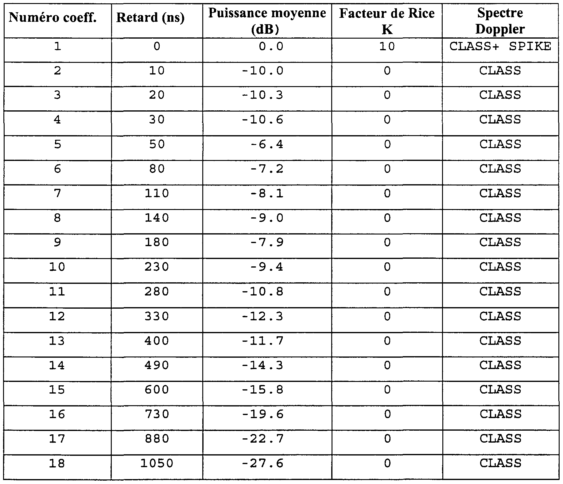
Ceux du modèle E sont donnés dans le tableau 7 ci- apres :Those of model E are given in table 7 below:
TABLEAU 7TABLE 7
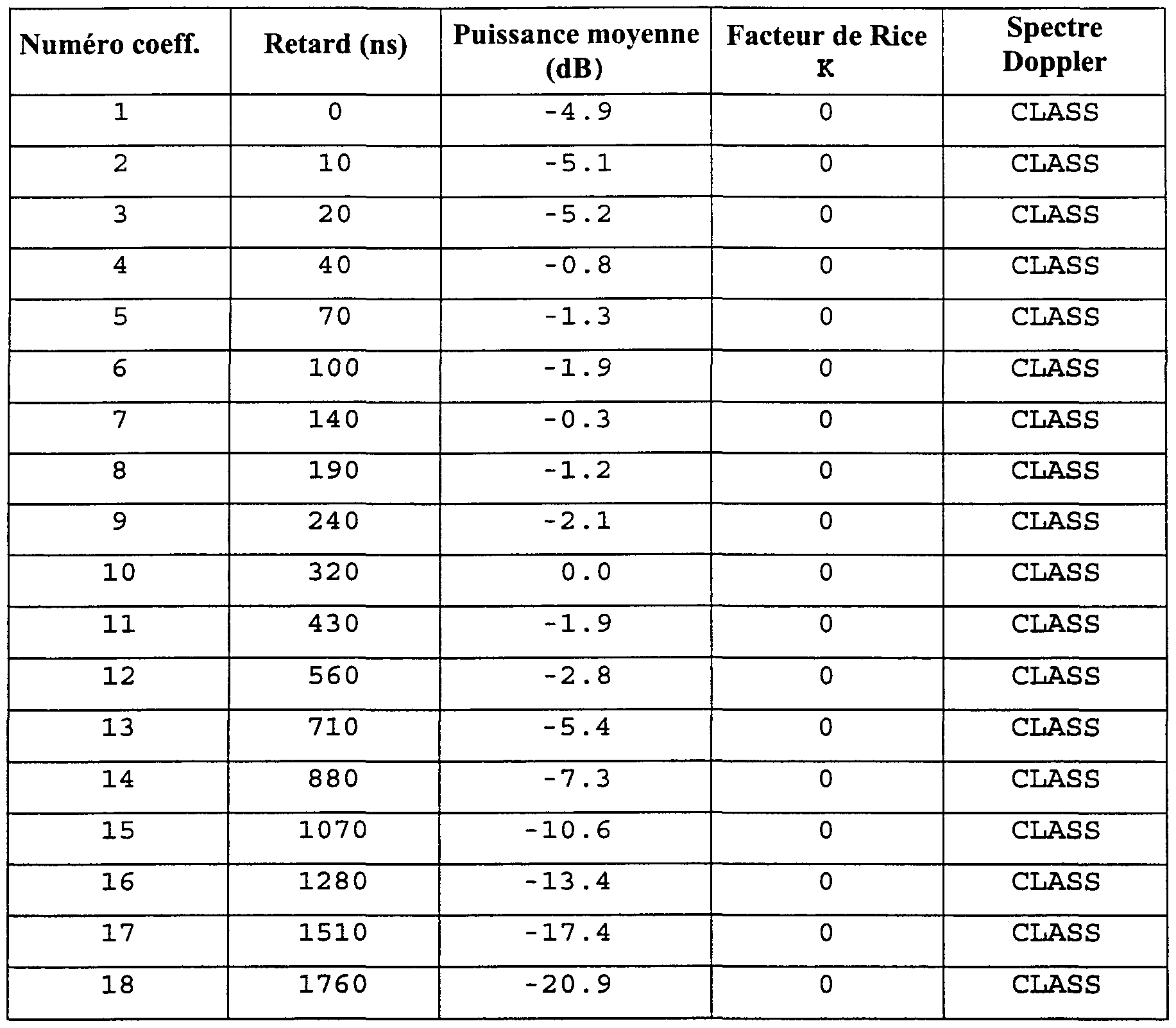
Claims
Priority Applications (4)
| Application Number | Priority Date | Filing Date | Title |
|---|---|---|---|
| DE60040747T DE60040747D1 (en) | 1999-09-13 | 2000-09-08 | PROCESS FOR COMMON DECODING AND REMOTE SIGNAL |
| US10/070,854 US7012976B1 (en) | 1999-09-13 | 2000-09-08 | Method for decoding and of joint equalization of a digital signal protected by a code defined by a trellis |
| JP2001524315A JP4559000B2 (en) | 1999-09-13 | 2000-09-08 | Method for decoding and joint equalization of digital signals protected by codes defined by trellis |
| EP00962592A EP1212873B1 (en) | 1999-09-13 | 2000-09-08 | Method for joint decoding and equalising of a digital signal protected by a trellis-defined code |
Applications Claiming Priority (2)
| Application Number | Priority Date | Filing Date | Title |
|---|---|---|---|
| FR99/11411 | 1999-09-13 | ||
| FR9911411A FR2798540B1 (en) | 1999-09-13 | 1999-09-13 | METHOD OF JOINT DECODING AND EQUALIZATION OF A DIGITAL SIGNAL PROTECTED BY A CODE DEFINED BY A MESH |
Publications (1)
| Publication Number | Publication Date |
|---|---|
| WO2001020861A1 true WO2001020861A1 (en) | 2001-03-22 |
Family
ID=9549770
Family Applications (1)
| Application Number | Title | Priority Date | Filing Date |
|---|---|---|---|
| PCT/FR2000/002491 Ceased WO2001020861A1 (en) | 1999-09-13 | 2000-09-08 | Method for joint decoding and equalising of a digital signal protected by a trellis-defined code |
Country Status (7)
| Country | Link |
|---|---|
| US (1) | US7012976B1 (en) |
| EP (1) | EP1212873B1 (en) |
| JP (1) | JP4559000B2 (en) |
| CN (1) | CN1158821C (en) |
| DE (1) | DE60040747D1 (en) |
| FR (1) | FR2798540B1 (en) |
| WO (1) | WO2001020861A1 (en) |
Families Citing this family (4)
| Publication number | Priority date | Publication date | Assignee | Title |
|---|---|---|---|---|
| US7502418B2 (en) * | 2001-12-18 | 2009-03-10 | Agere Systems Inc. | Method and apparatus for joint equalization and decoding of multilevel codes |
| US7782984B2 (en) * | 2002-08-30 | 2010-08-24 | Alcatel-Lucent Usa Inc. | Method of sphere decoding with low complexity and good statistical output |
| US8737460B2 (en) * | 2012-07-16 | 2014-05-27 | Seagate Technology, Llc | Equalizer and detector arrangement employing joint entropy-based calibration |
| CN115473777A (en) * | 2022-10-10 | 2022-12-13 | 北京睿信丰科技有限公司 | Adaptive SOQPSK modulation and demodulation method, terminal and receiver |
Citations (3)
| Publication number | Priority date | Publication date | Assignee | Title |
|---|---|---|---|---|
| EP0758167A1 (en) * | 1995-08-08 | 1997-02-12 | France Telecom | Weighted output decoding process using the Viterbi algorithm in blocks |
| EP0858196A1 (en) * | 1997-02-06 | 1998-08-12 | Alcatel | Equaliser and channel decoder |
| EP0889612A2 (en) * | 1997-07-02 | 1999-01-07 | Lucent Technologies Inc. | Viterbi decoder and decision feedback equalizer for coded modulation |
Family Cites Families (3)
| Publication number | Priority date | Publication date | Assignee | Title |
|---|---|---|---|---|
| JPH03291033A (en) * | 1990-04-06 | 1991-12-20 | Mitsubishi Electric Corp | Sum decoding circuit |
| US5432808A (en) * | 1993-03-15 | 1995-07-11 | Kabushiki Kaisha Toshiba | Compound semicondutor light-emitting device |
| US6426972B1 (en) * | 1998-06-19 | 2002-07-30 | Nxtwave Communications | Reduced complexity equalizer for multi mode signaling |
-
1999
- 1999-09-13 FR FR9911411A patent/FR2798540B1/en not_active Expired - Lifetime
-
2000
- 2000-09-08 CN CNB00815516XA patent/CN1158821C/en not_active Expired - Lifetime
- 2000-09-08 DE DE60040747T patent/DE60040747D1/en not_active Expired - Lifetime
- 2000-09-08 WO PCT/FR2000/002491 patent/WO2001020861A1/en not_active Ceased
- 2000-09-08 JP JP2001524315A patent/JP4559000B2/en not_active Expired - Lifetime
- 2000-09-08 US US10/070,854 patent/US7012976B1/en not_active Expired - Lifetime
- 2000-09-08 EP EP00962592A patent/EP1212873B1/en not_active Expired - Lifetime
Patent Citations (3)
| Publication number | Priority date | Publication date | Assignee | Title |
|---|---|---|---|---|
| EP0758167A1 (en) * | 1995-08-08 | 1997-02-12 | France Telecom | Weighted output decoding process using the Viterbi algorithm in blocks |
| EP0858196A1 (en) * | 1997-02-06 | 1998-08-12 | Alcatel | Equaliser and channel decoder |
| EP0889612A2 (en) * | 1997-07-02 | 1999-01-07 | Lucent Technologies Inc. | Viterbi decoder and decision feedback equalizer for coded modulation |
Non-Patent Citations (2)
| Title |
|---|
| HASHIMOTO T: "A LIST-TYPE REDUCED-CONSTRAINT GENERALIZATION OF THE VITERBI ALGORITHM", IEEE TRANSACTIONS ON INFORMATION THEORY,US,IEEE INC. NEW YORK, vol. 33, no. 6, 1 November 1987 (1987-11-01), pages 866 - 876, XP000575317, ISSN: 0018-9448 * |
| RYUJI KOHNO ET AL: "AN AUTOMATIC EQUALIZER INCLUDING A VITERBI DECODER FOR TRELLIS CODED MODULATION SYSTEM", INTERNATIONAL CONFERENCE ON ACOUSTICS, SPEECH & SIGNAL PROCESSING. ICASSP,US,NEW YORK, IEEE, vol. CONF. 14, 1989, pages 1368 - 1371, XP000090356 * |
Also Published As
| Publication number | Publication date |
|---|---|
| EP1212873B1 (en) | 2008-11-05 |
| CN1158821C (en) | 2004-07-21 |
| JP2003509964A (en) | 2003-03-11 |
| JP4559000B2 (en) | 2010-10-06 |
| FR2798540B1 (en) | 2001-11-23 |
| DE60040747D1 (en) | 2008-12-18 |
| FR2798540A1 (en) | 2001-03-16 |
| CN1390411A (en) | 2003-01-08 |
| US7012976B1 (en) | 2006-03-14 |
| EP1212873A1 (en) | 2002-06-12 |
Similar Documents
| Publication | Publication Date | Title |
|---|---|---|
| EP1362447B1 (en) | Method and system for the iterative encoding-decoding of streams of digital data encoded by spatio-temporal combinations, in multiple transmission and reception | |
| EP0891656B1 (en) | Data block convolutional coding device and method, and corresponding decoding method and device | |
| WO2002084931A1 (en) | Method for coding/decoding a stream of coded digital data with bit-interleaving in multiple transmission and in reception in the presence of intersymbol interference and corresponding system | |
| EP0808538B1 (en) | Iterative-structure digital signal reception device, and module and method therefor | |
| WO2001089164A1 (en) | Method and system for detecting and iterative decoding of received symbols, coupled with reevaluation of transmission channel coefficients | |
| EP2915302B9 (en) | Method and apparatus for demodulating q-ary gfsk signals | |
| EP3800813A1 (en) | Method and device for predicting the performance of a receiver in a communication system | |
| CN1172498C (en) | Adaptive Maximum Likelihood Sequence Detection Method | |
| FR2832876A1 (en) | METHOD AND DEVICE FOR ESTIMATING SIGNALS WITH MAXIMUM PROBABILITY ON THE BASIS OF A TRUSS, FOR ESTIMATING A BLIND COMMON CHANNEL AND FOR SIGNAL DETECTION | |
| FR2783120A1 (en) | DIGITAL EQUALIZATION PROCESS, AND RADIOCOMMUNICATION RECEIVER IMPLEMENTING SUCH A PROCESS | |
| FR2794589A1 (en) | ITERATIVE TDMA RADIO TRANSMISSION METHOD | |
| EP1212873B1 (en) | Method for joint decoding and equalising of a digital signal protected by a trellis-defined code | |
| Cuc et al. | Performances analysis of turbo codes, LDPC codes and polar codes using AWGN channel with and without inter symbol interference | |
| EP0981881B1 (en) | Equalising and decoding device for a frequency-selective digital transmission channel | |
| US6728322B1 (en) | Sequential decoder, and receiver using sequential decoder | |
| EP0858196A1 (en) | Equaliser and channel decoder | |
| EP0758167B1 (en) | Weighted output decoding process using the Viterbi algorithm in blocks | |
| EP0904649B1 (en) | Msle decoder with neural network | |
| EP1211857A1 (en) | Process and device of successive value estimations of numerical symbols, in particular for the equalization of a data communication channel of information in mobile telephony | |
| CN115473777A (en) | Adaptive SOQPSK modulation and demodulation method, terminal and receiver | |
| Niu et al. | Pilot-symbol-assisted LDPC coded BICM over correlated Rayleigh fading channels | |
| WO2020115423A1 (en) | Method for processing a stream of data in a receiver device | |
| EP1115233A1 (en) | Reduced state channel equalising method using symbol-by-symbol decisions |
Legal Events
| Date | Code | Title | Description |
|---|---|---|---|
| AK | Designated states |
Kind code of ref document: A1 Designated state(s): CN JP US |
|
| AL | Designated countries for regional patents |
Kind code of ref document: A1 Designated state(s): AT BE CH CY DE DK ES FI FR GB GR IE IT LU MC NL PT SE |
|
| 121 | Ep: the epo has been informed by wipo that ep was designated in this application | ||
| DFPE | Request for preliminary examination filed prior to expiration of 19th month from priority date (pct application filed before 20040101) | ||
| WWE | Wipo information: entry into national phase |
Ref document number: 2000962592 Country of ref document: EP |
|
| WWE | Wipo information: entry into national phase |
Ref document number: 10070854 Country of ref document: US |
|
| ENP | Entry into the national phase |
Ref country code: JP Ref document number: 2001 524315 Kind code of ref document: A Format of ref document f/p: F |
|
| WWE | Wipo information: entry into national phase |
Ref document number: 00815516X Country of ref document: CN |
|
| WWP | Wipo information: published in national office |
Ref document number: 2000962592 Country of ref document: EP |