WO1999023476A1 - Measuring the concentration of a substance - Google Patents
Measuring the concentration of a substance Download PDFInfo
- Publication number
- WO1999023476A1 WO1999023476A1 PCT/GB1998/001809 GB9801809W WO9923476A1 WO 1999023476 A1 WO1999023476 A1 WO 1999023476A1 GB 9801809 W GB9801809 W GB 9801809W WO 9923476 A1 WO9923476 A1 WO 9923476A1
- Authority
- WO
- WIPO (PCT)
- Prior art keywords
- fluorophor
- light
- signal
- concentration
- light source
- Prior art date
- Legal status (The legal status is an assumption and is not a legal conclusion. Google has not performed a legal analysis and makes no representation as to the accuracy of the status listed.)
- Ceased
Links
Classifications
-
- A—HUMAN NECESSITIES
- A61—MEDICAL OR VETERINARY SCIENCE; HYGIENE
- A61B—DIAGNOSIS; SURGERY; IDENTIFICATION
- A61B5/00—Measuring for diagnostic purposes; Identification of persons
- A61B5/68—Arrangements of detecting, measuring or recording means, e.g. sensors, in relation to patient
- A61B5/6846—Arrangements of detecting, measuring or recording means, e.g. sensors, in relation to patient specially adapted to be brought in contact with an internal body part, i.e. invasive
- A61B5/6847—Arrangements of detecting, measuring or recording means, e.g. sensors, in relation to patient specially adapted to be brought in contact with an internal body part, i.e. invasive mounted on an invasive device
- A61B5/6848—Needles
-
- A—HUMAN NECESSITIES
- A61—MEDICAL OR VETERINARY SCIENCE; HYGIENE
- A61B—DIAGNOSIS; SURGERY; IDENTIFICATION
- A61B5/00—Measuring for diagnostic purposes; Identification of persons
- A61B5/145—Measuring characteristics of blood in vivo, e.g. gas concentration or pH-value ; Measuring characteristics of body fluids or tissues, e.g. interstitial fluid or cerebral tissue
- A61B5/1455—Measuring characteristics of blood in vivo, e.g. gas concentration or pH-value ; Measuring characteristics of body fluids or tissues, e.g. interstitial fluid or cerebral tissue using optical sensors, e.g. spectral photometrical oximeters
- A61B5/1459—Measuring characteristics of blood in vivo, e.g. gas concentration or pH-value ; Measuring characteristics of body fluids or tissues, e.g. interstitial fluid or cerebral tissue using optical sensors, e.g. spectral photometrical oximeters invasive, e.g. introduced into the body by a catheter
-
- G—PHYSICS
- G01—MEASURING; TESTING
- G01N—INVESTIGATING OR ANALYSING MATERIALS BY DETERMINING THEIR CHEMICAL OR PHYSICAL PROPERTIES
- G01N21/00—Investigating or analysing materials by the use of optical means, i.e. using sub-millimetre waves, infrared, visible or ultraviolet light
- G01N21/62—Systems in which the material investigated is excited whereby it emits light or causes a change in wavelength of the incident light
- G01N21/63—Systems in which the material investigated is excited whereby it emits light or causes a change in wavelength of the incident light optically excited
- G01N21/64—Fluorescence; Phosphorescence
- G01N21/6408—Fluorescence; Phosphorescence with measurement of decay time, time resolved fluorescence
-
- G—PHYSICS
- G01—MEASURING; TESTING
- G01N—INVESTIGATING OR ANALYSING MATERIALS BY DETERMINING THEIR CHEMICAL OR PHYSICAL PROPERTIES
- G01N21/00—Investigating or analysing materials by the use of optical means, i.e. using sub-millimetre waves, infrared, visible or ultraviolet light
- G01N21/62—Systems in which the material investigated is excited whereby it emits light or causes a change in wavelength of the incident light
- G01N21/63—Systems in which the material investigated is excited whereby it emits light or causes a change in wavelength of the incident light optically excited
- G01N21/64—Fluorescence; Phosphorescence
- G01N21/6428—Measuring fluorescence of fluorescent products of reactions or of fluorochrome labelled reactive substances, e.g. measuring quenching effects, using measuring "optrodes"
-
- G—PHYSICS
- G01—MEASURING; TESTING
- G01N—INVESTIGATING OR ANALYSING MATERIALS BY DETERMINING THEIR CHEMICAL OR PHYSICAL PROPERTIES
- G01N21/00—Investigating or analysing materials by the use of optical means, i.e. using sub-millimetre waves, infrared, visible or ultraviolet light
- G01N21/75—Systems in which material is subjected to a chemical reaction, the progress or the result of the reaction being investigated
- G01N21/77—Systems in which material is subjected to a chemical reaction, the progress or the result of the reaction being investigated by observing the effect on a chemical indicator
- G01N21/7703—Systems in which material is subjected to a chemical reaction, the progress or the result of the reaction being investigated by observing the effect on a chemical indicator using reagent-clad optical fibres or optical waveguides
- G01N2021/7706—Reagent provision
- G01N2021/772—Tip coated light guide
Definitions
- the present invention relates to an apparatus and a method for determining the concentration of a substance.
- the invention relates to apparatus and a method for determining the concentration of oxygen within living tissue cells.
- say substance will be used in this specification to refer to the particular substance that an apparatus or method according to the invention is intended to detect.
- apparatus for measuring oxygen tension comprises a sensor in which a fluorophor is localised in a polymer and coated on an end surface of an optical fibre.
- a pulsed laser is used to apply pumping light to the fibre, which light is transmitted to the fluorophor.
- the fluorophor emits light, which travels back along the fibre to a detector.
- This sensor is advantageous in that it is relatively unreactive with biological tissue and will not affect living cells even after a prolonged contact with them, and in that it does not consume oxygen during detection.
- the invention provides a sensor for detecting concentration of an assay substance comprising an optical fibre having an end surface on which is disposed a polymer body within which a multiplicity of particles is immobilised, on which particles is adsorbed a fluorophor, the polymer being such as to allow the assay substance to permeate into the body to come into contact with the fluorophor, and the fluorophor being selected as having a fluorescent activity which is measurably altered in the presence of the assay substance.
- the pattern of distribution of the fluorophor in a sensor embodying the invention is particularly effective in transmitting a high proportion of the light generated by the fluorophor back along the fibre for detection.
- the senor comprises a single optical fibre which carries light from a pumping light source to the polymer body and which carries light emitted by the fluorophor from the polymer body to a detector. This further simplifies the construction of the sensor.
- numeric aperture of the optical fibre it has been found to be advantageous for the numeric aperture of the optical fibre to be greater than 0.3, and, in some embodiments, yet more advantageous to be greater than 0.4. In particularly preferred embodiments, a numerical aperture on the range 0.45 to 0.5 is selected. Numerical apertures in these ranges are particularly suited to collection of light from the fluorophor in the body of active material.
- An optical fibre for use in a sensor embodying the invention is advantageously of less than 300 m in diameter.
- a diameter of approximately 200 ⁇ has been found to be particularly suitable.
- the particles may suitably be silica gel particles. It is generally preferable for such particles to be of as small a size as possible, since this maximises the surface area on which dye can be adsorbed and also promotes cross-linking of the polymer matrix.
- silica particles having an average diameter of 5 ⁇ m are readily available. It is preferable that the silica particles are of an average diameter of 5 ⁇ m or less.
- the assay substance is oxygen.
- a suitable polymer is a silicone rubber.
- a suitable fluorophor for use in such embodiments is a ruthenium complex dye, for example tris (4 , 7-diphenyl- 1, 10-phenanthroline) .
- ruthenium complex dye for example tris (4 , 7-diphenyl- 1, 10-phenanthroline) .
- many other dyes could also be used, a prime desirable property being that the dye has a relatively long fluorescent lifetime; preferably in the order of several ⁇ s when unquenched by the assay substance.
- a dye with a short fluorescent lifetime could be used. If this is the case, a correspondingly fast light source must be used to excite the fluorophor, and the light source must be controlled by suitably fast switching circuitry.
- the invention provides a method of making a sensor for measuring the concentration of an assay substance in which a fluorescent dye is adsorbed onto a multiplicity of solid particles, subsequently dispersing the particles in a liquid polymer, applying the liquid polymer and the particles contained in it to an end surface of an optical fibre, and curing the liquid polymer to form a polymer body on the end surface of the optical fibre, the dye having been selected as to have a fluorescent activity which is measurably altered in the presence of the assay substance, and the polymer having been selected to be permeable to the assay surface when in its cured condition.
- the optical fibre typically comprises a core, a cladding, and a protective buffer coating which covers the cladding.
- the method includes removal of the buffer coating from an end portion of the fibre prior to application of the liquid polymer, and subsequent to curing of the liquid polymer, a protective coating is applied to cover the said end portion and the polymer body.
- the protective coating may be formed from the same liquid polymer as is applied to the end portion of the fibre.
- the polymer of the protective coating may be substantially pure or it may incorporate opaque particles such as carbon black. This latter arrangement isolates the fluorophor from ambient light, while the former arrangement may offer greater acceptability for use in contact with biological tissue.
- the method may include insertion of the said end portion through a hollow member, such that its end face, on which the liquid polymer is applied, projects from the hollow member, and subsequent to curing of the polymer layer, a protective coating is applied to cover an end face of the tubular member and the polymer body.
- the hollow member may be a hollow needle made, for example, from steel or a ceramic material. The arrangement described in this paragraph has the advantage of having high mechanical durability.
- the invention provides a system for measuring the concentration of an assay substance comprising: a sensor having a sensing body including fluorophor, which fluorophor has a fluorescent activity which is measurably altered in relation the concentration of the assay substance and light conveying means for conveying light to and from the fluorophor; a pumping light source which, in operation, applies light to the light conveying means to activate the fluorophor; a detector for detecting light emitted by the fluorophor in the polymer body and for generating a signal in response thereto; analysing apparatus for analysing the signal generated by the detector, and calculating from that signal the concentration of assay substance detected by the sensor; characterised in that the detector operates to detect transient change in light emitted by the fluorophor simultaneously with the pumping light source operating to apply light to the optical fibre.
- the light source may be a source other than a laser, for example, one or more light emitting diodes.
- a system may operate by analysing the change in the light emitted by the fluorophor which occurs after the light source starts to operate.
- the system analyses the kinetics of the growth in light output which takes place in response to operation of the light source.
- it is normal to operate the light source for a time which is substantially larger than the time during which light emitted by the fluorophor changes following the start of operation of the light source.
- the light source is operated repeatedly, the analysing means being operable to calculate an average value of a plurality of calculated concentration values. This arrangement ensures that random variations in any one measurement do not substantially affect the accuracy of the system.
- the senor prefferably has a single optical fibre through which light is transmitted to the fluorophor, and through which light from the fluorophor is returned to the detector.
- the system typically further comprises an optical means, such as beam splitter, to split light emerging from the optical fibre from light which is entering the fibre from the light source.
- the invention provides an analysis system for calculating a lifetime period of an exponentially varying signal comprising: three or more integrating circuits, each having an input for receiving the signal an output on which is generated a signal representative of the value of the input signal integrated over time; for each integrator, a switch circuit having a control input and operative to selectively connect or disconnect the input of the associated integrator to the signal in dependance upon the state of its control input; timing means responsive to commencement of exponential variation of the signal, and operative to generate control signals for application to the control inputs of the switch circuits, the control signals being timed such that the three switches connect their respective integrating circuits, in turn, to the signal for three equal and. consecutive time periods during exponential change of the signal; and computing means operative to receive output signals from the integrating circuits, and perform on them analysis whereby the lifetime value of the exponential change can be determined.
- This system is particularly useful in systems of the above defined aspects of the invention, but can also find application in other systems in which high-speed analysis of exponentially varying signals is needed. Its particular advantage is that the mathematically difficult task of performing the integration is carried out in high-speed, low-cost dedicated hardware.
- the computing means can therefore be of relatively low performance, since it need perform only a few mathematically simple operations .
- the integrating circuits can conveniently be implemented as operational amplifier integrators.
- the computing means will typically comprise a digital computer, with a suitable analogue-to-digital conversion circuit being provided between the integrating circuits and the computing means.
- the computing means comprises a general-purpose, microprocessor-based computer, such as a desktop personal computer.
- Figure 1 is a cross-sectional view of a sensor for use in apparatus embodying the invention
- Figure 2 is an alternative sensor to that shown in Figure 1;
- FIG. 3 is a schematic diagram of a sensing apparatus embodying the invention.
- FIG. 4 is an overview of the signal processing circuit construction of apparatus embodying the invention.
- Figure 5 is diagram of fluorescent activity in a sensor plotted against time during operation of a system embodying the invention
- Figure 6 is a diagram showing the relative timing of signals within the system (the horizontal time axis being not to scale) ;
- Figure 7 is a circuit diagram of an electronic switching circuit suitable for fast switching of an LED.
- FIGs. 1 and 2 there is shown two alternative sensor arrangements which embody, or form part of various aspects of the invention.
- the sensor 10 comprises an optical fibre which is formed from a light transmitting core 12 surrounded by a cladding 14.
- a protective buffer layer 16 surrounds the cladding 14 to give the fibre mechanical strength and robustness .
- the diameter of the fibre is approximately 200 ⁇ m.
- the particular fibre chosen was a TECS (t.m.) optical fibre manufactured by 3M (t.m.).
- the fibre has an end surface 20.
- An end portion of the fibre 18, extending from the end surface 20, is bared of the buffer layer 16.
- the body comprises a quantity of moulded polymer formed as a curved projection from the end surface 20.
- a multiplicity of particles 24 are dispersed.
- Each of the particles 24 is formed from silica gel.
- the average diameter of the particles is approximately
- a fluorescent dye - tris (4, 7-diphenyl-l, 10- phenanthroline) Ru(II)Cl is adsorbed on the surface of the silica gel particles prior to their being incorporated into the body. In this way, the dye is immobilised within the body 22.
- the end portion 18 and the body 22 are covered in a moulded protective coating 26 of the same polymer as forms the body in a pure form (that is, containing no silica particles) .
- the protective coating 26 serves to provide mechanical protection for the body 22 and isolates it from the clinical environment in which it will be used.
- the end portion 18 is inserted into a tubular rigid needle 28 which has a central axial through bore.
- the needle 28 is arranged such that the end surface 20 of the fibre is disposed substantially at a free open end of the bore.
- a protective coating 30 is applied to cover the body 22 and a surrounding end surface of the needle 28.
- the needle 28 is also sealed to the buffer layer 16.
- the system comprises a light source constituted by a light emitting diode (LED) 40.
- the light from the LED 40 passes through a 450 nm acetate filter 42 to pass into a first optical fibre 44.
- a y-beam splitter is formed by a 2 x 2 splitter 46, one port of which is unused.
- a first optical fibre 44 is connected to a first port on a first side of the splitter 46.
- a second optical fibre 48 is connected to a port on the second side of the splitter 46 such that light entering the splitter 46 through the first optical fibre 44 is transmitted to the second optical fibre 48.
- the second optical fibre 48 connects the splitter 46 to a coupler 50.
- a third optical fibre 52 is connected to a second port on the first side of the slitter 46.
- the third optical fibre 52 connects the splitter 46 to a detector unit 54, which will be described in more detail below.
- the LED 40, the splitter 46 and the detector unit 54 are all disposed within a common housing.
- the coupler 50 permits optical connection of a fibre external of the housing, through a wall 56, to the second optical fibre 48.
- a sensor 10 as described with reference to Fig. 1 or Fig. 2, is connected to the coupler 50.
- light is emitted from the LED 40, passes through the acetate filter 42, into the first optical fibre 44. From there, it passes through the splitter 46 into the second optical fibre 48, and then through the coupler 50, into the sensor 10. This light causes fluorescent activity within the body 22 on the end surface of the sensor 10. Such fluorescent activity causes light to be produced with an emission spectrum peaking at around 600 nm. This light travels from the sensor 10, through the coupler 50, into the second optical fibre 48. It then passes through the splitter 46 and into the third optical fibre 52, to be carried to the detector unit 54.
- the detector unit 54 comprises a coupling lens 60, a 590 nm long-pass filter 62 and a photomultiplier tube 64.
- Light from the third optical fibre 52 is received by the coupling lens 60, passes through the filter 62 to be received by the photomultiplier tube 64.
- the photomultiplier tube 64 generates an electrical output signal which is proportional to the amount of light which it receives. The apparatus and method for processing this signal will be described below.
- the electrical signal from the photomultiplier tube 64 is received into the signal processing circuits at a connector 70.
- the first stage of processing the signal fed to the connector is carried out by an amplifier stage 72.
- the amplifier stage comprises an operational amplifier connected as an inverting DC amplifier.
- the output of the amplifier stage at 74 is a signal with a voltage proportional to the amount of light being received by the photomultiplier tube 64.
- the output from the amplifier stage is fed to an input of an integrating stage 76.
- the integrating stage 76 comprises three identical integrating channels, each of which comprises a conventionally designed operational amplifier integration circuit comprising an operational amplifier 80 with a capacitor 82 connected between its output and its non-inverting input. The inverting input of the operational amplifier 80 is grounded.
- the integrating circuit has a series resistor 84 on its input .
- the integrating stage 76 further comprises three high-speed electronic channel switches 86. Each switch 86 connects a respective one of the integrating channels to the input of the integrating stage 76. A respective electronic resetting switch 88 is also connected across each of the capacitors 82 to permit discharge of the capacitor 82 to reset the integrating circuit between integration operations.
- the integrating stage 76 has three outputs 90, each connected to the output of a respective one of the integration channels.
- the outputs 90 of the integration stage 76 are each connected to a respective input of a multi-channel analogue-to-digital (A/D) converter 92.
- the A/D converter 92 generates a digital output signal which is fed to a computer 94 for processing.
- the above described circuit is controlled by a timing stage 96.
- the timing stage 96 has an output 98 to control the LED 40, outputs 100,102,104 each of which controls a respective one of the electronic channel switches 86, a control output 106 for controlling operation of the A/D converter 92 and a reset output 108 which simultaneously actuates the three resetting switches 88.
- the timing stage also has a start triggering input line 110.
- a system control circuit 112 is provided to initiate operation of the timing stage 96 through the triggering input line.
- the system control circuit 112 also controls operation of the computer through an interrupt line 114.
- the fluorophor in the sensor 10 begins to fluoresce.
- An oxygen-dependant component of the amount of light being emitted by such fluorescence grows exponentially to a steady maximum value within a few ⁇ s .
- a lifetime value ⁇ for the exponential growth varies in dependance upon the degree of fluorescent activity in the sensor 10. Since the fluorescent activity is determined by the concentration of oxygen at the probe tip, if the value of ⁇ can be determined, the concentration of oxygen can then be found.
- the signal generated by the output of the amplifier stage 72 (and therefore the amount of light reaching the photomultiplier tube 64 from fluorescent activity in the sensor 10) is represented by the line 120. This is plotted against time on the x-axis.
- the LED 40 is energised at t zero .
- the photomultiplier tube detects a small amount of the light from the LED 40 leaking through the beam splitter 46, shown by the step change in level at 122.
- the photomultiplier tube 64 begins to detect light emitted by fluorescence in the sensor. This light increases exponentially, resulting in an exponential output from the amplifier stage 72, as represented in Figure 5.
- II represents an integral from time tO to tl
- 12 represents an integral from time tl to t2
- 13 represents an integral from time t2 to t3.
- Each of the intervals' tl-to, t2-tl and t3-t2 is of time ⁇ t .
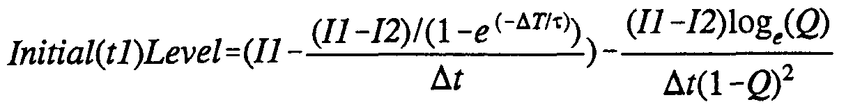
- the initial and the final levels may also be determined from:
- the integrations required to determine the values of II, 12 and 13 are performed by the three integrating channels of the integrating stage 76. Furthermore, the integration is performed repeatedly on a multiplicity of energisations of the LED 40 thereby to average the integration value, so as to mitigate the effect of random variations in the integral value which can arise from noise or other sources.
- time is represented horizontally.
- the horizontal lines each represents the variation in time of the logic state of a particular signal line within the system.
- Each line in Figure 6 is labelled with a reference numeral which corresponds to the hardware device or signal line described above which is controlled by that signal.
- the lower part of Figure 6 shows a complete measurement cycle.
- the indicated interval A - B is 1 second.
- a measurement cycle is initiated by the control circuit 112 driving the start triggering input line 110 low (active) .
- the interrupt line 114 is driven high (inactive) .
- the reset line 108 is pulsed to active high, and then brought low again, the falling edge of the pulse arriving exactly one second after the triggering input line 110 was activated.
- Each acquisition sequence comprises a multiplicity of integration sequences, each extending over a variable cycle period shown as D in the upper part of Figure 6.
- D the cycle period shown as D in the upper part of Figure 6.
- the number of integration sequences within an acquisition sequence is varied in dependance upon the length of each integration sequence, such that the last integration sequence commences not longer than 900ms after the start of the acquisition sequence.
- Each integration sequence comprises the following steps :
- the LED control output 98 is driven high, to turn on the LED 40.
- the output 100 is driven high to turn on the first channel switch 86; between times tl and t2, the output 102 is driven high to turn on the second channel switch 86, and between times tl and t3, the output 104 is driven high to turn on the third channel switch 86.
- a delay is imposed (up to the total cycle period D) to allow all fluorescent activity to fully decay .
- the cycle period D As the cycle period D is varied, the time interval between L and tO remains fixed. As the cycle period D is varied, the time interval between L and tO remains fixed. As ⁇ t is varied, the ratio of LED on-time (L to t3) to the cycle period D remains constant (in this embodiment, at a ratio exceeding 1:8).
- the principle reason for such variation is to ensure that the three integrations take place over a time period in which the level of fluorescent emission is varying rapidly. It has been found that it is preferable to adjust the cycle period D such that the relationship:
- each of the integration circuits will have performed an integration of the value of the fluorescent activity which corresponds to a respective one of the values of integrals II, 12 or 13 in the formulae given above.
- the integration will have been performed a multiplicity of times, thereby mitigating the effect of any random fluctuation in the signal received from the photodetector 74.
- Such fluctuations can result from both electronic noise and from the quantised nature of the photon flux being detected.
- a measurement sequence E of approximately 100ms then starts.
- the interrupt line 114 and the control output 106 are then activated to trigger operation of the A/D converter 92, which reads the outputs of the three integrating circuits, and generates a digital value corresponding to each of them. This digital value is then made available to be read by the computer 94.
- the reset output 108 is activated to reset the integrating circuits in readiness for the next acquisition cycle.
- the computer 94 can then calculate a value for ⁇ by performing only simple arithmetical operations plus a single logarithmic computation. These calculations can readily be performed by a computer of a comparatively modest power within the time interval between successive acquisition sequences. This is in notable contrast to the alternative possibility of using the computer to perform the integration - a process which would require a very substantially longer processing time, such that a very powerful (and expensive) computer would be required to perform such calculations in real time.
- ⁇ 0 is the lifetime value of the probe in the absence of oxygen.
- the computer can display this for immediate reading by an operator, or the value can be processed and stored in any desired manner.
- the computer may maintain a table of oxygen concentration values, may provide an instantaneous display of oxygen concentration, or drive a plotter to generate a continuous record of the variation in oxygen concentration over time.
- hydrogen ion concentration could be measured using a sulphonic acid anilide or other aromatic hydrocarbon fluorophor, a rhodamine dye, or hydroxypyrenetrisulfonic acid
- oxygen concentration could alternatively be measured using a fluoranthene dye, pyrenebutyric acid, polycyclic, homocyclic or heterocyclic aromatic hydrocarbon or lanthanide and/or osmium complexes
- carbon dioxide concentration could be measured using ⁇ - methylumbelliferone and sodium bicarbonate, and sulphur dioxide or hydrogen peroxide could be detected by means of a fluorophor comprising metal complex in combination with a long-chain alkyl or alkane group ammonium or sulphate ion.
- the invention can also be applied to detection of enzymes using a fluorophor comprising hydrolase oxidases or dehydrogenases of the type of enzyme to be detected. It will be appreciated that the particular formulation of fluorophor required for a particular measuring task can be selected by experimentation in a routine manner by a suitably skilled person.
Landscapes
- Health & Medical Sciences (AREA)
- Life Sciences & Earth Sciences (AREA)
- Physics & Mathematics (AREA)
- General Health & Medical Sciences (AREA)
- Pathology (AREA)
- Chemical & Material Sciences (AREA)
- Immunology (AREA)
- Engineering & Computer Science (AREA)
- General Physics & Mathematics (AREA)
- Biochemistry (AREA)
- Analytical Chemistry (AREA)
- Heart & Thoracic Surgery (AREA)
- Medical Informatics (AREA)
- Public Health (AREA)
- Veterinary Medicine (AREA)
- Chemical Kinetics & Catalysis (AREA)
- Optics & Photonics (AREA)
- Nuclear Medicine, Radiotherapy & Molecular Imaging (AREA)
- Surgery (AREA)
- Molecular Biology (AREA)
- Animal Behavior & Ethology (AREA)
- Biomedical Technology (AREA)
- Biophysics (AREA)
- Spectroscopy & Molecular Physics (AREA)
- Plasma & Fusion (AREA)
- Investigating, Analyzing Materials By Fluorescence Or Luminescence (AREA)
- Investigating Or Analysing Materials By The Use Of Chemical Reactions (AREA)
- Saccharide Compounds (AREA)
- Investigating Or Analyzing Non-Biological Materials By The Use Of Chemical Means (AREA)
- External Artificial Organs (AREA)
- Measuring Or Testing Involving Enzymes Or Micro-Organisms (AREA)
Abstract
Description
Claims
Priority Applications (8)
| Application Number | Priority Date | Filing Date | Title |
|---|---|---|---|
| JP2000519291A JP4221150B2 (en) | 1997-11-03 | 1998-06-19 | Substance concentration measurement system |
| AT98930909T ATE235049T1 (en) | 1997-11-03 | 1998-06-19 | MEASURING THE CONCENTRATION OF A SUBSTANCE |
| DK98930909T DK1029233T3 (en) | 1997-11-03 | 1998-06-19 | Measuring the concentration of a substance |
| AU81188/98A AU746460B2 (en) | 1997-11-03 | 1998-06-19 | Measuring the concentration of a substance |
| EP98930909A EP1029233B1 (en) | 1997-11-03 | 1998-06-19 | Measuring the concentration of a substance |
| DE69812400T DE69812400T2 (en) | 1997-11-03 | 1998-06-19 | MEASURING THE CONCENTRATION OF A SUBSTANCE |
| CA002309089A CA2309089C (en) | 1997-11-03 | 1998-06-19 | Measuring the concentration of a substance |
| US09/559,780 US6531097B1 (en) | 1997-11-03 | 2000-04-27 | Measuring the concentration of a substance |
Applications Claiming Priority (2)
| Application Number | Priority Date | Filing Date | Title |
|---|---|---|---|
| GB9723229.2 | 1997-11-03 | ||
| GB9723229A GB2330903C (en) | 1997-11-03 | 1997-11-03 | Sensing the concentration of a substance |
Related Child Applications (1)
| Application Number | Title | Priority Date | Filing Date |
|---|---|---|---|
| US09/559,780 Continuation US6531097B1 (en) | 1997-11-03 | 2000-04-27 | Measuring the concentration of a substance |
Publications (1)
| Publication Number | Publication Date |
|---|---|
| WO1999023476A1 true WO1999023476A1 (en) | 1999-05-14 |
Family
ID=10821519
Family Applications (1)
| Application Number | Title | Priority Date | Filing Date |
|---|---|---|---|
| PCT/GB1998/001809 Ceased WO1999023476A1 (en) | 1997-11-03 | 1998-06-19 | Measuring the concentration of a substance |
Country Status (12)
| Country | Link |
|---|---|
| US (1) | US6531097B1 (en) |
| EP (1) | EP1029233B1 (en) |
| JP (1) | JP4221150B2 (en) |
| AT (1) | ATE235049T1 (en) |
| AU (1) | AU746460B2 (en) |
| CA (1) | CA2309089C (en) |
| DE (1) | DE69812400T2 (en) |
| DK (1) | DK1029233T3 (en) |
| ES (1) | ES2195356T3 (en) |
| GB (1) | GB2330903C (en) |
| PT (1) | PT1029233E (en) |
| WO (1) | WO1999023476A1 (en) |
Cited By (6)
| Publication number | Priority date | Publication date | Assignee | Title |
|---|---|---|---|---|
| US6664111B2 (en) * | 2001-08-22 | 2003-12-16 | 3M Innovative Properties Company | Fluorescence based oxygen sensor systems |
| CN102495028A (en) * | 2011-11-18 | 2012-06-13 | 江苏大学 | Mixing concentration on-line detection method and device thereof |
| EP1887344A4 (en) * | 2005-05-27 | 2012-12-05 | Kirin Holdings Kk | METHOD OF MEASURING THE OXYGEN QUANTITY IN A HERMETICALLY SEALED CONTAINER AND DEVICE THEREFORE FOR DRILLING THE HERMETICALLY SEALED CONTAINER |
| EP2721382A4 (en) * | 2011-05-18 | 2015-04-15 | Samuel Walker Inman | IRREGULAR EXCITATION OF OPTICAL SENSORS |
| EP2550523A4 (en) * | 2010-03-25 | 2018-01-24 | Mocon, Inc. | Luminescence lifetime based analyte sensing instruments and calibration technique |
| US11988583B2 (en) | 2018-08-31 | 2024-05-21 | Lucid Scientific, Inc. | Measurement of a dynamic system |
Families Citing this family (19)
| Publication number | Priority date | Publication date | Assignee | Title |
|---|---|---|---|---|
| US7670844B2 (en) * | 2004-01-20 | 2010-03-02 | The Curators Of The University Of Missouri | Supported molecular biofluid viscosity sensors for in vitro and in vivo use |
| GB0505036D0 (en) * | 2005-03-11 | 2005-04-20 | Oxford Optronix Ltd | An optical measurement sensor |
| GB2447966B8 (en) * | 2007-03-29 | 2012-02-08 | Fiberlogix Internat Ltd | Improved optical chemical sensor |
| US8081313B2 (en) * | 2007-05-24 | 2011-12-20 | Airbus Operations Limited | Method and apparatus for monitoring gas concentration in a fluid |
| JP4944006B2 (en) * | 2007-12-17 | 2012-05-30 | 株式会社山武 | Temperature sensor and temperature measurement method |
| DE102008011578A1 (en) * | 2008-02-28 | 2009-09-03 | Endress + Hauser Conducta Gesellschaft für Mess- und Regeltechnik mbH + Co. KG | Photo-luminescence sensor for determining concentration of analyte in medium, has coloring carrier with photoluminescence coloring, where light source is provided for stimulating photoluminescence |
| JP5225773B2 (en) * | 2008-07-09 | 2013-07-03 | アズビル株式会社 | Temperature sensor and temperature measurement method |
| GB0813715D0 (en) * | 2008-07-28 | 2008-09-03 | Airbus Uk Ltd | A monitor and a method for measuring oxygen concentration |
| JP5365279B2 (en) * | 2009-03-17 | 2013-12-11 | ソニー株式会社 | Luminescent material, luminescent material composite and method for producing the same, fluorescent labeling reagent and method for producing the same, and light emitting device |
| GB0918212D0 (en) * | 2009-10-16 | 2009-12-02 | Univ Strathclyde | Intelligent pigments and plastics |
| US8694069B1 (en) | 2009-12-21 | 2014-04-08 | Kosense, LLC | Fiber-optic probe with embedded peripheral sensors for in-situ continuous monitoring |
| GB201012078D0 (en) | 2010-07-19 | 2010-09-01 | Oxford Optronix Ltd | Concentration measurement using luminescene |
| GB2486677A (en) * | 2010-12-22 | 2012-06-27 | Agilent Technologies Inc | Ceramic injection needle for analysis system |
| AU2012255683B2 (en) * | 2011-05-13 | 2016-04-14 | Adelaide Research & Innovation Pty Ltd | A method of and a system for characterising a material |
| JP5839575B2 (en) * | 2012-04-06 | 2016-01-06 | 本田技研工業株式会社 | Fuel cell internal oxygen concentration measuring device |
| CN103630509A (en) * | 2013-12-03 | 2014-03-12 | 江苏大学 | On-line pesticide concentration detection device and method |
| US9097670B1 (en) * | 2014-03-06 | 2015-08-04 | Stardust Materials, LLC | System for measuring dye concentration in liquids |
| EP3702759A1 (en) | 2019-02-26 | 2020-09-02 | Nokia Technologies Oy | Method and apparatus for fluorescence lifetime measurement |
| US11193916B2 (en) | 2019-05-02 | 2021-12-07 | SciLogica Corp. | Calibration of a gas sensor |
Citations (5)
| Publication number | Priority date | Publication date | Assignee | Title |
|---|---|---|---|---|
| EP0252578A2 (en) * | 1986-07-02 | 1988-01-13 | John E. Shulze | Sensor system using fluorometric decay measurements |
| EP0442060A2 (en) * | 1990-02-16 | 1991-08-21 | The BOC Group, Inc. | Luminescence sensing with ratiometric measurement |
| US5304809A (en) * | 1992-09-15 | 1994-04-19 | Luxtron Corporation | Luminescent decay time measurements by use of a CCD camera |
| WO1994010553A1 (en) * | 1992-10-23 | 1994-05-11 | Optex Biomedical, Inc. | Fibre-optic probe for the measurement of fluid parameters |
| US5351268A (en) * | 1990-12-04 | 1994-09-27 | Luxtron Corporation | Modular luminescence-based measuring system using fast digital signal processing |
Family Cites Families (5)
| Publication number | Priority date | Publication date | Assignee | Title |
|---|---|---|---|---|
| US4557900A (en) * | 1982-09-28 | 1985-12-10 | Cardiovascular Devices, Inc. | Optical sensor with beads |
| US5043285A (en) * | 1987-07-09 | 1991-08-27 | Allied-Signal Inc. | Optical detection of oxygen |
| US5173432A (en) * | 1987-12-14 | 1992-12-22 | The Dow Chemical Company | Apparatus and method for measuring the concentration or partial pressure of oxygen |
| EP0329297A3 (en) * | 1988-02-16 | 1990-12-05 | Medex, Inc. | Method and apparatus for measuring partial pressure of oxygen in a fluid |
| GB2265709A (en) * | 1992-03-25 | 1993-10-06 | David Russell Blake | Reactive oxygen species measuring device |
-
1997
- 1997-11-03 GB GB9723229A patent/GB2330903C/en not_active Expired - Fee Related
-
1998
- 1998-06-19 DE DE69812400T patent/DE69812400T2/en not_active Expired - Lifetime
- 1998-06-19 AU AU81188/98A patent/AU746460B2/en not_active Ceased
- 1998-06-19 ES ES98930909T patent/ES2195356T3/en not_active Expired - Lifetime
- 1998-06-19 AT AT98930909T patent/ATE235049T1/en active
- 1998-06-19 EP EP98930909A patent/EP1029233B1/en not_active Expired - Lifetime
- 1998-06-19 CA CA002309089A patent/CA2309089C/en not_active Expired - Fee Related
- 1998-06-19 JP JP2000519291A patent/JP4221150B2/en not_active Expired - Fee Related
- 1998-06-19 DK DK98930909T patent/DK1029233T3/en active
- 1998-06-19 PT PT98930909T patent/PT1029233E/en unknown
- 1998-06-19 WO PCT/GB1998/001809 patent/WO1999023476A1/en not_active Ceased
-
2000
- 2000-04-27 US US09/559,780 patent/US6531097B1/en not_active Expired - Fee Related
Patent Citations (5)
| Publication number | Priority date | Publication date | Assignee | Title |
|---|---|---|---|---|
| EP0252578A2 (en) * | 1986-07-02 | 1988-01-13 | John E. Shulze | Sensor system using fluorometric decay measurements |
| EP0442060A2 (en) * | 1990-02-16 | 1991-08-21 | The BOC Group, Inc. | Luminescence sensing with ratiometric measurement |
| US5351268A (en) * | 1990-12-04 | 1994-09-27 | Luxtron Corporation | Modular luminescence-based measuring system using fast digital signal processing |
| US5304809A (en) * | 1992-09-15 | 1994-04-19 | Luxtron Corporation | Luminescent decay time measurements by use of a CCD camera |
| WO1994010553A1 (en) * | 1992-10-23 | 1994-05-11 | Optex Biomedical, Inc. | Fibre-optic probe for the measurement of fluid parameters |
Cited By (9)
| Publication number | Priority date | Publication date | Assignee | Title |
|---|---|---|---|---|
| US6664111B2 (en) * | 2001-08-22 | 2003-12-16 | 3M Innovative Properties Company | Fluorescence based oxygen sensor systems |
| EP1887344A4 (en) * | 2005-05-27 | 2012-12-05 | Kirin Holdings Kk | METHOD OF MEASURING THE OXYGEN QUANTITY IN A HERMETICALLY SEALED CONTAINER AND DEVICE THEREFORE FOR DRILLING THE HERMETICALLY SEALED CONTAINER |
| EP2550523A4 (en) * | 2010-03-25 | 2018-01-24 | Mocon, Inc. | Luminescence lifetime based analyte sensing instruments and calibration technique |
| EP2721382A4 (en) * | 2011-05-18 | 2015-04-15 | Samuel Walker Inman | IRREGULAR EXCITATION OF OPTICAL SENSORS |
| US9075011B2 (en) | 2011-05-18 | 2015-07-07 | Samuel Walker Inman | Irregular excitation of optical sensors |
| CN102495028A (en) * | 2011-11-18 | 2012-06-13 | 江苏大学 | Mixing concentration on-line detection method and device thereof |
| CN102495028B (en) * | 2011-11-18 | 2013-10-23 | 江苏大学 | A method and device for online detection of mixed drug concentration |
| US11988583B2 (en) | 2018-08-31 | 2024-05-21 | Lucid Scientific, Inc. | Measurement of a dynamic system |
| US12287261B2 (en) | 2018-08-31 | 2025-04-29 | Lucid Scientific, Inc. | Measurement of a dynamic system |
Also Published As
| Publication number | Publication date |
|---|---|
| GB2330903B (en) | 2002-05-15 |
| CA2309089A1 (en) | 1999-05-14 |
| AU746460B2 (en) | 2002-05-02 |
| PT1029233E (en) | 2003-07-31 |
| US6531097B1 (en) | 2003-03-11 |
| DE69812400T2 (en) | 2004-01-22 |
| DE69812400D1 (en) | 2003-04-24 |
| AU8118898A (en) | 1999-05-24 |
| EP1029233B1 (en) | 2003-03-19 |
| GB2330903A (en) | 1999-05-05 |
| CA2309089C (en) | 2009-02-10 |
| JP2002529682A (en) | 2002-09-10 |
| EP1029233A1 (en) | 2000-08-23 |
| JP4221150B2 (en) | 2009-02-12 |
| GB2330903C (en) | 2002-05-15 |
| GB9723229D0 (en) | 1998-01-07 |
| ATE235049T1 (en) | 2003-04-15 |
| ES2195356T3 (en) | 2003-12-01 |
| DK1029233T3 (en) | 2003-06-16 |
Similar Documents
| Publication | Publication Date | Title |
|---|---|---|
| EP1029233B1 (en) | Measuring the concentration of a substance | |
| JP3249820B2 (en) | Modular measurement system for high-speed digital signal processing of luminescence | |
| US5102625A (en) | Apparatus for monitoring a chemical concentration | |
| JP2738500B2 (en) | Equipment for measuring biological activity in culture vessels | |
| US4833091A (en) | Sensor system | |
| EP0252578A2 (en) | Sensor system using fluorometric decay measurements | |
| US5093266A (en) | Sensor system | |
| KR101385786B1 (en) | Measuring system and measuring method, in particular for determining blood glucose | |
| WO1993006459A1 (en) | Dual-wavelength photometer and fiber optic sensor probe | |
| JPH08503773A (en) | Light emitting diode / infrared light emitting diode Low cost means to increase measurement sensitivity of near infrared device | |
| GB1589450A (en) | Automatic blood analysis apparatus and method | |
| US10524707B2 (en) | System and method for photoluminescence detection | |
| EP0635570A2 (en) | Blood culture sensor station utilizing two distinct light sources | |
| WO2001086263A3 (en) | Apparatus and methods for detecting explosives and other substances | |
| GB2178847A (en) | Testing for the presence of living organisms at the surface of an object | |
| EP0329297A2 (en) | Method and apparatus for measuring partial pressure of oxygen in a fluid | |
| US5300769A (en) | Method and system of compensating for signal artifacts in a fiber-optic sensing system | |
| US20020190221A1 (en) | Electronic test standard for fluorescence detectors | |
| CN113933268A (en) | Optical detection device and optical detection method | |
| JPS58137723A (en) | Apparatus for measuring temperature | |
| US4162851A (en) | Simultaneous photometering method and assembly for multi-dimensional measurements concerning biologically related materials | |
| Carswell et al. | Optical oxygen sensor based on RUDPP fluorescence quenching | |
| CA1326772C (en) | Sensor system | |
| CN117571679A (en) | An oxygen partial pressure measurement method and system based on laser and single photon detector | |
| Perez et al. | Design of a multi-parameter substance analyzer |
Legal Events
| Date | Code | Title | Description |
|---|---|---|---|
| AK | Designated states |
Kind code of ref document: A1 Designated state(s): AU CA JP NZ US |
|
| AL | Designated countries for regional patents |
Kind code of ref document: A1 Designated state(s): AT BE CH CY DE DK ES FI FR GB GR IE IT LU MC NL PT SE |
|
| 121 | Ep: the epo has been informed by wipo that ep was designated in this application | ||
| DFPE | Request for preliminary examination filed prior to expiration of 19th month from priority date (pct application filed before 20040101) | ||
| ENP | Entry into the national phase |
Ref document number: 2309089 Country of ref document: CA Ref country code: CA Ref document number: 2309089 Kind code of ref document: A Format of ref document f/p: F |
|
| WWE | Wipo information: entry into national phase |
Ref document number: 09559780 Country of ref document: US |
|
| WWE | Wipo information: entry into national phase |
Ref document number: 1998930909 Country of ref document: EP |
|
| WWE | Wipo information: entry into national phase |
Ref document number: 81188/98 Country of ref document: AU |
|
| WWP | Wipo information: published in national office |
Ref document number: 1998930909 Country of ref document: EP |
|
| WWG | Wipo information: grant in national office |
Ref document number: 81188/98 Country of ref document: AU |
|
| WWG | Wipo information: grant in national office |
Ref document number: 1998930909 Country of ref document: EP |