WO1999023046A1 - Slag for cementing a well, in particular an oil well - Google Patents
Slag for cementing a well, in particular an oil well Download PDFInfo
- Publication number
- WO1999023046A1 WO1999023046A1 PCT/FR1998/002339 FR9802339W WO9923046A1 WO 1999023046 A1 WO1999023046 A1 WO 1999023046A1 FR 9802339 W FR9802339 W FR 9802339W WO 9923046 A1 WO9923046 A1 WO 9923046A1
- Authority
- WO
- WIPO (PCT)
- Prior art keywords
- addition
- particles
- hydraulic binder
- microsilica
- dairy according
- Prior art date
- Legal status (The legal status is an assumption and is not a legal conclusion. Google has not performed a legal analysis and makes no representation as to the accuracy of the status listed.)
- Ceased
Links
Classifications
-
- C—CHEMISTRY; METALLURGY
- C09—DYES; PAINTS; POLISHES; NATURAL RESINS; ADHESIVES; COMPOSITIONS NOT OTHERWISE PROVIDED FOR; APPLICATIONS OF MATERIALS NOT OTHERWISE PROVIDED FOR
- C09K—MATERIALS FOR MISCELLANEOUS APPLICATIONS, NOT PROVIDED FOR ELSEWHERE
- C09K8/00—Compositions for drilling of boreholes or wells; Compositions for treating boreholes or wells, e.g. for completion or for remedial operations
- C09K8/42—Compositions for cementing, e.g. for cementing casings into boreholes; Compositions for plugging, e.g. for killing wells
- C09K8/46—Compositions for cementing, e.g. for cementing casings into boreholes; Compositions for plugging, e.g. for killing wells containing inorganic binders, e.g. Portland cement
-
- C—CHEMISTRY; METALLURGY
- C04—CEMENTS; CONCRETE; ARTIFICIAL STONE; CERAMICS; REFRACTORIES
- C04B—LIME, MAGNESIA; SLAG; CEMENTS; COMPOSITIONS THEREOF, e.g. MORTARS, CONCRETE OR LIKE BUILDING MATERIALS; ARTIFICIAL STONE; CERAMICS; REFRACTORIES; TREATMENT OF NATURAL STONE
- C04B18/00—Use of agglomerated or waste materials or refuse as fillers for mortars, concrete or artificial stone; Treatment of agglomerated or waste materials or refuse, specially adapted to enhance their filling properties in mortars, concrete or artificial stone
- C04B18/04—Waste materials; Refuse
- C04B18/14—Waste materials; Refuse from metallurgical processes
- C04B18/146—Silica fume
-
- C—CHEMISTRY; METALLURGY
- C04—CEMENTS; CONCRETE; ARTIFICIAL STONE; CERAMICS; REFRACTORIES
- C04B—LIME, MAGNESIA; SLAG; CEMENTS; COMPOSITIONS THEREOF, e.g. MORTARS, CONCRETE OR LIKE BUILDING MATERIALS; ARTIFICIAL STONE; CERAMICS; REFRACTORIES; TREATMENT OF NATURAL STONE
- C04B28/00—Compositions of mortars, concrete or artificial stone, containing inorganic binders or the reaction product of an inorganic and an organic binder, e.g. polycarboxylate cements
- C04B28/02—Compositions of mortars, concrete or artificial stone, containing inorganic binders or the reaction product of an inorganic and an organic binder, e.g. polycarboxylate cements containing hydraulic cements other than calcium sulfates
- C04B28/04—Portland cements
-
- Y—GENERAL TAGGING OF NEW TECHNOLOGICAL DEVELOPMENTS; GENERAL TAGGING OF CROSS-SECTIONAL TECHNOLOGIES SPANNING OVER SEVERAL SECTIONS OF THE IPC; TECHNICAL SUBJECTS COVERED BY FORMER USPC CROSS-REFERENCE ART COLLECTIONS [XRACs] AND DIGESTS
- Y02—TECHNOLOGIES OR APPLICATIONS FOR MITIGATION OR ADAPTATION AGAINST CLIMATE CHANGE
- Y02W—CLIMATE CHANGE MITIGATION TECHNOLOGIES RELATED TO WASTEWATER TREATMENT OR WASTE MANAGEMENT
- Y02W30/00—Technologies for solid waste management
- Y02W30/50—Reuse, recycling or recovery technologies
- Y02W30/91—Use of waste materials as fillers for mortars or concrete
Definitions
- the present invention relates to a slag for cementing a well, in particular a well for exploring or exploiting underground deposits, such as hydrocarbon or geothermal deposits.
- Well cementing is a very specific operation requiring the injection of a cement slag through tubes (casing or tubing) by pumping from the surface.
- One of the primary purposes of these operations is to cement the annular space between the outside of the casing tube and the drilled hole.
- Other cementing operations well known to those skilled in the art, may also be concerned, for example the installation of plugs or “squeeze” operations.
- the well, interior space and annular space is filled with a fluid, generally the drilling fluid of the previous drilling phase, or with a fluid of similar composition.
- the cement slag must be placed in the annular space by circulation while expelling the original annular fluid to the surface.
- the main functions of petroleum cement slag are in particular to seal the annular space to the fluids contained in rocks, gas, oil or water and to mechanically hold the tubes in the drilled hole.
- the compressive strength characteristic is essential.
- the rheology control is also very important, as well as the possibility of using additives adapted to particular conditions, for example filtrate reducers, retarders or setting accelerators , dispersing agents, defoamers, lightening or weighting agents.
- cement formulations are known which lead to very superior mechanical properties, as described for example in European patent EP 0 518 777, but which are not suitable as well cementing slag, if only due to their insufficient proportion of water.
- a slag which comprises: - a hydraulic binder from the group consisting of Portland cements class G (API), Portland cements class H (API) and other hydraulic binders with a low aluminate content, - a microsilica with a particle size in the range 0.1 to 0 , 50 micrometers, at a rate of 20 to 35% by weight relative to the hydraulic binder.
- API Portland cements class G
- API Portland cements class H
- other hydraulic binders with a low aluminate content - a microsilica with a particle size in the range 0.1 to 0 , 50 micrometers, at a rate of 20 to 35% by weight relative to the hydraulic binder.
- the amount of water is slightly greater than that just sufficient to fill the voids between the grains of the composition, so as to ensure the essential rheology.
- the slag composition of the invention still has one or more of the following characteristics:
- the hydraulic binder is a Portland cement, class G.
- the hydraulic binder is composed of particles whose sizes are distributed in the range 0.1-100 micrometers.
- the hydraulic binder consists of particles whose sizes are distributed in the range 10 to 50 micrometers.
- Microsilica is a silica fume from the zirconium industry. - The microsilica is present at a rate of 20-30% by weight relative to the hydraulic binder.
- the microsilica is present at a rate of 20 to 25% by weight relative to the hydraulic binder.
- the microsilica is made up of agglomerates of particles whose average size is close to 3 micrometers.
- the addition of medium particles is an organic addition of plastic balls, for example of polystyrene.
- the addition of medium particles is a mineral addition chosen from silica, clay, glass beads, metal salts, baryte, hematite and ilmenite.
- the addition of medium particles is a mineral addition of siliceous particles.
- the addition of medium particles is present at a rate of 20 to 30% by weight relative to the hydraulic binder.
- the addition of medium particles is a mineral addition of silica sand whose particles have sizes distributed in the range 5-200 micrometers.
- the addition of medium particles is a mineral addition of silica sand whose particles have an average size close to 50 micrometers.
- the addition of medium particles is a mineral addition of ground quartz.
- the water-soluble agent is composed of a highly ionized polymer or copolymer derived from sulfonated functions and / or from phosphate, phosphonate, carboxylate.
- the water-soluble agent is an agent from the group consisting of naphthalene sulfonate, lignosulfate, melanin and the like.
- the water-soluble agent is a fluidizer containing sulfonated or phosphated functions.
- the amount of water is preferably included in the / 23046
- Figure 3 shows the ⁇ shear stress curves ⁇ at 20 ° C for five slag formulations of different particle sizes
- Figure 4 shows the ⁇ shear ⁇ stress curves at 20 ° C for two slag formulations differing in particular in their water content.
- a Portland cement was used corresponding to petroleum standards Class G.
- the cement powder of a very wide particle size range (between 0.1 and 100 ⁇ m) having a D50 value of approximately 14 ⁇ m and a BET specific surface of approximately 1 m / g, has grains of very varied angular shapes.
- the D50 value represents the particle size below which 50% of the particles have a dimension smaller than this D50 value.
- Silica used as a mineral addition of medium particles, is in the form of ground quartz and is mainly composed of silicon oxide, traces of aluminum, iron and potassium.
- the very angular grains have a granular range of between 0.5 and 200 ⁇ m, preferably between 1 and 150 ⁇ m, a D50 value of approximately 42 ⁇ m, and a specific surface area measured by BET of 0.46 m / g .
- microsilica used is of structure is of amorphous structure, the size of the agglomerates constituting the powder varies from 1 to 50 ⁇ m. Observation with a scanning electron microscope shows that the powder grains are made up of associations of spherical elementary particles (0.1 to 2 ⁇ m). These particles are amorphous microspheres with a density close to 2.2. The D50 value is 3 ⁇ m.
- the superplasticizer is the fluidizer D80 (Dowell) which is a sodium polynaphthalene sulfonate containing 40% by mass of dry matter and 60% of water.
- This polymer makes it possible to fluidize the mixture and to reduce the amount of water used for the same viscosity. It also acts as a retarder.
- the D50 values of the cement, of the average particles of the silica type and of the microsilica are respectively 14, 42 and 3 ⁇ m. It is clear that the three granular products used (cement, addition and microsilica) have particle sizes which are relatively distributed among themselves in a specific manner taking into account the value of their D50. We will not depart from the invention if we use other particles equivalent in size and function.
- microsilicates are incorporated into the following formulation (% by weight relative to the cement):
- Portland cement class G 100 silica (crushed quartz): 20 fluidizer D80 (Do ell): 1.8 Total water: 27 microsilica: 24
- Formulation A with microsilica a Formulation B with microsilica b Formulation C with microsilica c
- ECD equivalent density in circulation
- Formulation A is therefore the most efficient.
- the viscosity is more favorable with the fluidizer of formulation A (fig. 2).
- formulation B is due to specific interactions between the thinner acrylate functions and the microsilica from the zirconium industry. It is therefore preferable to formulate with this type of microsilica fluidizers containing sulfonated or phosphated functions and to avoid the acrylate functions.
- the main danger when placing the cement slag is the generation of pressures greater than the fracturing pressures of the rocks crossed during drilling.
- the pressures generated by the injection of fluids, in particular cement, through the completion of a well are due to friction.
- an important factor is the control of the flow of the cement slag and therefore the knowledge of its rheological behavior. From a particular choice of operational parameters, the acceptable pressure and pressure losses are deduced, taking into account the rheology of the cement slag.
- composition is made by optimizing the rheology from a certain amount of fixed water.
- Formulation A Microsilica a at 24% and silica at 20%
- Formulation Bl Microsilica a at 30% and silica at 20%
- Formulation B2 Microsilica a at 35% and silica at 20%
- Formulation Cl Microsilica a at " 24% and silica at 40%
- Formulation C2 Microsilica a at 24% and silica at 60%
- the relative percentage of average particles compared to fine particles is determined if we compare the flow curves Cl and C2 compared to that of A.
- Formulations Cl and C2 contain more medium particles compared to fine particles (microsilica), and then have a rheology (curves Cl and C2 in FIG. 3) greater than formulations Bl-B2, A, all of which have an amount of average particles lower than that of fine particles.
- the cement slags having a rheology comparable to that of Cl or C2, are ill-suited, or even not suitable for the cementing of oil wells.
- ⁇ (Pa) represents the values and stresses measured for
- formulation A which contains water in a water to cement ratio of 0.27 has a compressive strength 3.5 times greater than a conventional formulation of cement for wells which contains water in a ratio water on cement greater than 0.4.
- Figure 4 shows a lower viscosity curve for formulation (A), which further limits the pressure drops in the well.
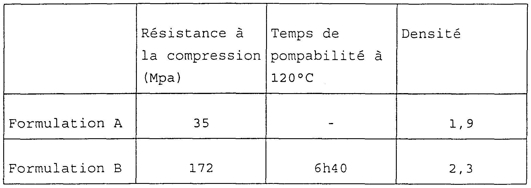
- the compressive strength, the time of pumpability, that is to say the time necessary for the establishment of the slag in the well and for the solidification of the slag, and the density optimized to control the pressure during the partial establishment in the case of hot wells and deep, are reported in Table 4 below. This table confirms the performance of the cement slag based on formulation A, in particular for the cementing of hot and deep wells.
Landscapes
- Chemical & Material Sciences (AREA)
- Engineering & Computer Science (AREA)
- Ceramic Engineering (AREA)
- Materials Engineering (AREA)
- Organic Chemistry (AREA)
- Structural Engineering (AREA)
- Inorganic Chemistry (AREA)
- Life Sciences & Earth Sciences (AREA)
- General Life Sciences & Earth Sciences (AREA)
- Chemical Kinetics & Catalysis (AREA)
- Environmental & Geological Engineering (AREA)
- Civil Engineering (AREA)
- Curing Cements, Concrete, And Artificial Stone (AREA)
- Physical Or Chemical Processes And Apparatus (AREA)
- Soil Conditioners And Soil-Stabilizing Materials (AREA)
Abstract
Description
LAITIER DE CIMENTATION D'UN PUITS, NOTAMMENT D'UN PUITS WELL CEMENTING A WELL, ESPECIALLY A WELL
PETROLIEROILER
DESCRIPTIONDESCRIPTION
Domaine techniqueTechnical area
La présente invention concerne un laitier de cimentation d'un puits, notamment d'un puits d'exploration ou d'exploitation de gisements souterrains, tels les gisements d'hydrocarbures ou géothermiques.The present invention relates to a slag for cementing a well, in particular a well for exploring or exploiting underground deposits, such as hydrocarbon or geothermal deposits.
Les cimentationε de puits sont des opérations très spécifiques nécessitant l'injection d'un laitier de ciment à travers des tubes (casing ou tubing) par pompage à partir de la surface. Un des but premiers de ces opérations est de cimenter l'espace annulaire entre l'extérieur du tube de cuvelage et le trou foré. D'autres opérations de cimentation, bien connues de l'homme du métier, peuvent également être concernées, par exemple les mises en place de bouchons ou des opérations de «squeeze» . Le puits, espace intérieur et espace annulaire, est rempli par un fluide, généralement le fluide de forage de la phase de forage précédente, ou par un fluide de composition proche. Le laitier de ciment doit être mis en place dans l'espace annulaire par circulation tout en chassant vers la surface le fluide annulaire d'origine. Les fonctions principales des laitiers de ciment pétroliers sont notamment d'assurer une étanchéité de 1 ' espace annulaire aux fluides contenus dans les roches, gaz, huile ou eau et de maintenir mécaniquement les tubes dans le trou foré. Pour cela, la caractéristique de résistance à la compression est primordiale. Compte tenu de la mise en place du laitier par circulation, le contrôle de la rhéologie est également très important, ainsi que la possibilité d'utiliser des additifs adaptés à des conditions particulières, par exemple des réducteurs de filtrat, des retardateurs ou accélérateurs de prise, des agents de dispersion, des antimousses, des allégeants ou des alourdissants.Well cementing is a very specific operation requiring the injection of a cement slag through tubes (casing or tubing) by pumping from the surface. One of the primary purposes of these operations is to cement the annular space between the outside of the casing tube and the drilled hole. Other cementing operations, well known to those skilled in the art, may also be concerned, for example the installation of plugs or “squeeze” operations. The well, interior space and annular space, is filled with a fluid, generally the drilling fluid of the previous drilling phase, or with a fluid of similar composition. The cement slag must be placed in the annular space by circulation while expelling the original annular fluid to the surface. The main functions of petroleum cement slag are in particular to seal the annular space to the fluids contained in rocks, gas, oil or water and to mechanically hold the tubes in the drilled hole. For this, the compressive strength characteristic is essential. Taking into account the installation of the slag by circulation, the rheology control is also very important, as well as the possibility of using additives adapted to particular conditions, for example filtrate reducers, retarders or setting accelerators , dispersing agents, defoamers, lightening or weighting agents.
État de la technique antérieureState of the art
Les formulations courantes d'un laitier de ciment pour cimentation de puits pétroliers comportent une quantité d'eau de l'ordre de 45% du poids du ciment, ce qui limite considérablement les propriétés mécaniques du laitier durci, notamment sa résistance à la compression.Current formulations of a cement slag for cementing oil wells include an amount of water of the order of 45% of the weight of the cement, which considerably limits the mechanical properties of hardened slag, in particular its resistance to compression.
On connaît d'autre part des formulations de ciment qui conduisent à des propriétés mécaniques très supérieures, comme décrit par exemple dans le brevet européen EP 0 518 777, mais qui ne conviennent pas comme laitier de cimentation de puits, ne serait-ce qu'en raison de leur proportion d'eau insuffisante.On the other hand, cement formulations are known which lead to very superior mechanical properties, as described for example in European patent EP 0 518 777, but which are not suitable as well cementing slag, if only due to their insufficient proportion of water.
Exposé de l'inventionStatement of the invention
Le problème se pose par conséquent de définir une composition optimisée de laitier dont la rhéologie convienne pour la cimentation d'un puits pétrolier ou analogue, qui comporte une quantité d'eau significativement inférieure à celle des laitiers préconisés jusqu'à présent pour cette application, et qui, après durcissement, présente des caractéristiques mécaniques très supérieures à celles des laitiers de cimentation de l'art antérieur. Ces résultats sont obtenus, selon l'invention, avec un laitier qui comporte : - un liant hydraulique du groupe constitué par les ciments Portland classe G (API) , les ciments Portland classe H (API) et les autres liants hydrauliques à faible teneur en aluminates, - une microsilice de granulométrie comprise dans la gamme 0,1 à 0,50 micromètres, à raison de 20 à 35% en poids par rapport au liant hydraulique.The problem therefore arises of defining an optimized slag composition, the rheology of which is suitable for cementing an oil well or the like, which comprises a quantity of water significantly lower than that of the slag hitherto recommended for this application, and which, after hardening, has mechanical characteristics far superior to those of the cementing slag of the prior art. These results are obtained, according to the invention, with a slag which comprises: - a hydraulic binder from the group consisting of Portland cements class G (API), Portland cements class H (API) and other hydraulic binders with a low aluminate content, - a microsilica with a particle size in the range 0.1 to 0 , 50 micrometers, at a rate of 20 to 35% by weight relative to the hydraulic binder.
- un ajout de particules moyennes, minéral et/ou organique, de granulométrie comprise dans la gamme 0,5-200 micromètres, à raison de; 20 à 35% en poids par rapport au liant hydraulique, la quantité dudit ajout de particules moyennes étant inférieure ou égale à la quantité de microsilice,- an addition of medium, inorganic and / or organic particles, of particle size included in the range 0.5-200 micrometers, at a rate of; 20 to 35% by weight relative to the hydraulic binder, the amount of said addition of medium particles being less than or equal to the amount of microsilica,
- un agent superplastifiant et/ou fluidifiant hydrosoluble en proportion comprise entre 1% et 3% en poids par rapport au liant hydraulique, eta water-soluble superplasticizer and / or fluidizer in a proportion of between 1% and 3% by weight relative to the hydraulic binder, and
- de l'eau en quantité au plus égale à 30% du poids du liant hydraulique.- water in an amount at most equal to 30% of the weight of the hydraulic binder.
De préférence, pour une composition donnée, la quantité d'eau est légèrement supérieure à celle juste suffisante pour remplir les vides entre les grains de la composition, de façon à assurer la rhéologie indispensable .Preferably, for a given composition, the amount of water is slightly greater than that just sufficient to fill the voids between the grains of the composition, so as to ensure the essential rheology.
Dans des modes de réalisation préférés, la composition de laitier de l'invention présente encore une ou plusieurs des caractéristiques suivantes :In preferred embodiments, the slag composition of the invention still has one or more of the following characteristics:
- Le liant hydraulique est un ciment Portland classe G.- The hydraulic binder is a Portland cement, class G.
- Le 'liant hydraulique est constitué de particules dont les grosseurs sont réparties dans la gamme 0,1-100 micromètres.- The hydraulic binder is composed of particles whose sizes are distributed in the range 0.1-100 micrometers.
- Le liant hydraulique est constitué de particules dont les grosseurs sont réparties dans la gamme 10 à 50 micromètres.- The hydraulic binder consists of particles whose sizes are distributed in the range 10 to 50 micrometers.
- La microsilice est une fumée de silice provenant de l'industrie du zirconium. - La microsilice est présente à raison de 20-30% en poids par rapport au liant hydraulique.- Microsilica is a silica fume from the zirconium industry. - The microsilica is present at a rate of 20-30% by weight relative to the hydraulic binder.
- La microsilice est présente à raison de 20 à 25% en poids par rapport au liant hydraulique. - La microsilice est constituée d'agglomérat de particules dont la grosseur moyenne est voisine de 3 micromètres.- The microsilica is present at a rate of 20 to 25% by weight relative to the hydraulic binder. - The microsilica is made up of agglomerates of particles whose average size is close to 3 micrometers.
- L'ajout de particules moyennes est un ajout organique de billes de matière plastique, par exemple de polystyrène. -7 - The addition of medium particles is an organic addition of plastic balls, for example of polystyrene. - 7
- L'ajout de particules moyennes est un ajout minéral choisi parmi la silice, l'argile, les billes de verre, des sels métalliques, la baryte, l'hématite et 1 ' ilménite . - L'ajout de particules moyennes est un ajout minéral de particules siliceuses.- The addition of medium particles is a mineral addition chosen from silica, clay, glass beads, metal salts, baryte, hematite and ilmenite. - The addition of medium particles is a mineral addition of siliceous particles.
- L'ajout de particules moyennes est présent à raison de 20 à 30% en poids par rapport au liant hydraulique.- The addition of medium particles is present at a rate of 20 to 30% by weight relative to the hydraulic binder.
- L'ajout de particules moyennes est un ajout minéral de sable siliceux dont les particules ont des grosseurs réparties dans la gamme 5-200 micromètres.- The addition of medium particles is a mineral addition of silica sand whose particles have sizes distributed in the range 5-200 micrometers.
- L'ajout de particules moyennes est un ajout minéral de sable siliceux dont les particules ont une grosseur moyenne voisine de 50 micromètres. - L'ajout de particules moyennes est un ajout minéral de quartz broyé.- The addition of medium particles is a mineral addition of silica sand whose particles have an average size close to 50 micrometers. - The addition of medium particles is a mineral addition of ground quartz.
- L'agent hydrosoluble est composé de polymère ou de copolymère fortement ionisé dérivé de fonctions sulfonées et/ou de phosphate, phosphonate, carboxylate.- The water-soluble agent is composed of a highly ionized polymer or copolymer derived from sulfonated functions and / or from phosphate, phosphonate, carboxylate.
- L'agent hydrosoluble est un agent du groupe constitué par le naphtalène sulfonate, le lignosulfate , la mélanine et analogues.- The water-soluble agent is an agent from the group consisting of naphthalene sulfonate, lignosulfate, melanin and the like.
- L'agent hydrosoluble est un fluidifiant contenant des fonctions sulfonées ou phosphatées.- The water-soluble agent is a fluidizer containing sulfonated or phosphated functions.
- La quantité d'eau est de préférence comprise dans la /23046- The amount of water is preferably included in the / 23046
gamme 20-30% du poids du liant hydraulique.range 20-30% of the weight of the hydraulic binder.
Brève description des dessinsBrief description of the drawings
On décrira ci-après des exemples de réalisation de l'invention et des essais comparatifs, en référence aux figures du dessin joint.Examples of embodiments of the invention and comparative tests will be described below, with reference to the figures in the accompanying drawing.
- La figure 1 montre les courbes de contraintes τ cisaillement γ à 80°C de trois formulations de laitier qui diffèrent par la microsilice utilisée ;- Figure 1 shows the stress curves τ shear γ at 80 ° C of three slag formulations which differ in the microsilica used;
- la figure 2 montre les courbes de contraintes τ - cisaillement γ à 80°C pour deux formulations de laitier qui diffèrent par la nature du fluidifiant utilisé ;- Figure 2 shows the stress curves τ - shear γ at 80 ° C for two slag formulations which differ in the nature of the fluidizer used;
- la figure 3 montre les courbes de contraintes τ cisaillement γ à 20°C pour cinq formulations de laitier de granulométries différentes, et la figure 4 montre les courbes de contraintes τ cisaillement γ à 20°C pour deux formulations de laitier différant notamment par leur teneur en eau.- Figure 3 shows the τ shear stress curves γ at 20 ° C for five slag formulations of different particle sizes, and Figure 4 shows the τ shear γ stress curves at 20 ° C for two slag formulations differing in particular in their water content.
Exposé détaillé des modes de réalisationDetailed description of the embodiments
Dans les exemples suivants, on a utilisé un ciment Portland correspondant aux normes pétrolières Classe G. La poudre de ciment, d'une étendue granulométrique très large (entre 0,1 et 100 μm) ayant une valeur D50 d'environ 14 μm et une surface spécifique BET d'environ 1 m /g, a des grains de formes anguleuses très variées.In the following examples, a Portland cement was used corresponding to petroleum standards Class G. The cement powder, of a very wide particle size range (between 0.1 and 100 μm) having a D50 value of approximately 14 μm and a BET specific surface of approximately 1 m / g, has grains of very varied angular shapes.
La valeur D50 représente la taille de particule en dessous de laquelle 50 % des particules ont une dimension inférieure à cette valeur D50. La silice, utilisée comme ajout minéral de particules moyennes, est sous forme de quartz broyé et est composée majoritairement d'oxyde de silicium, de traces d'aluminium, de fer et de potassium. Les grains, très anguleux, ont une étendue granulaire comprise entre 0,5 et 200 μm, de préférence entre 1 et 150 μm, une valeur D50 d'environ 42 μm, et une surface spécifique mesurée par BET de 0,46 m /g.The D50 value represents the particle size below which 50% of the particles have a dimension smaller than this D50 value. Silica, used as a mineral addition of medium particles, is in the form of ground quartz and is mainly composed of silicon oxide, traces of aluminum, iron and potassium. The very angular grains have a granular range of between 0.5 and 200 μm, preferably between 1 and 150 μm, a D50 value of approximately 42 μm, and a specific surface area measured by BET of 0.46 m / g .
La microsilice employée (microsilice a) est de structure est de structure amorphe, la taille des agglomérats constituant la poudre varie de 1 à 50 μm. L'observation au microscope électronique à balayage montre que les grains de poudres sont constitués d'associations de particules élémentaires sphériques (0,1 à 2 μm) . Ces particules sont des microsphères amorphes de densité proche de 2,2. La valeur de D50 est de 3 μm.The microsilica used (microsilica a) is of structure is of amorphous structure, the size of the agglomerates constituting the powder varies from 1 to 50 μm. Observation with a scanning electron microscope shows that the powder grains are made up of associations of spherical elementary particles (0.1 to 2 μm). These particles are amorphous microspheres with a density close to 2.2. The D50 value is 3 μm.
Enfin, le superplastifiant est le fluidifiant D80 (Dowell) qui est un polynaphtalène sulfonate de sodium contenant 40 % en masse de matière sèche et 60 % d'eau.Finally, the superplasticizer is the fluidizer D80 (Dowell) which is a sodium polynaphthalene sulfonate containing 40% by mass of dry matter and 60% of water.
Ce polymère permet de fluidifier le mélange et de diminuer la quantité d'eau utilisée pour une même viscosité. Il agit également comme retardateur de prise.This polymer makes it possible to fluidize the mixture and to reduce the amount of water used for the same viscosity. It also acts as a retarder.
Ainsi, les valeurs D50 du ciment, des particules moyennes du type silice et de la microsilice sont respectivement 14, 42 et 3 μm. Il est clair que les trois produits granulaires utilisés (ciment, ajout et microsilice) ont des tailles de particules qui se répartissent relativement entre elles d'une façon spécifique compte tenu de la valeur de leur D50. On ne sortira pas de l'invention si l'on utilise d'autres particules équivalentes en taille et en fonction.Thus, the D50 values of the cement, of the average particles of the silica type and of the microsilica are respectively 14, 42 and 3 μm. It is clear that the three granular products used (cement, addition and microsilica) have particle sizes which are relatively distributed among themselves in a specific manner taking into account the value of their D50. We will not depart from the invention if we use other particles equivalent in size and function.
EXEMPLE I : Influence de la provenance de la microsilice On formule des composition de laitier avec les trois microsilices différentes du tableau 1 ci après.EXAMPLE I Influence of the Origin of the Microsilica Slag compositions are formulated with the three different microsilices in Table 1 below.
TABLEAU 1TABLE 1
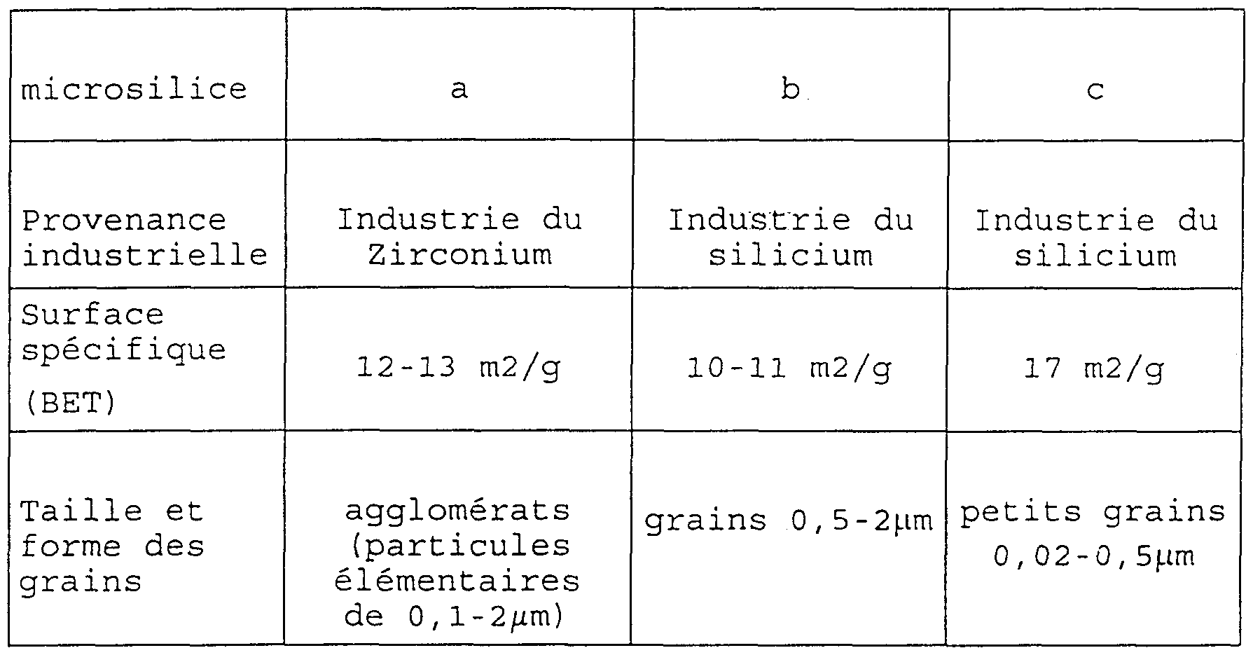
Ces microsilices sont incorporées à la formulation suivante (% en poids par rapport au ciment) :These microsilicates are incorporated into the following formulation (% by weight relative to the cement):
ciment Portland classe G : 100 silice (quartz broyé) : 20 fluidifiant D80 (Do ell) : 1,8 Eau totale : 27 microsilice: 24Portland cement class G: 100 silica (crushed quartz): 20 fluidizer D80 (Do ell): 1.8 Total water: 27 microsilica: 24
Formulation A avec microsilice a Formulation B avec microsilice b Formulation C avec microsilice cFormulation A with microsilica a Formulation B with microsilica b Formulation C with microsilica c
Les propriétés rheologiques sont apparentes sur la figure 1.The rheological properties are shown in Figure 1.
La viscosité la plus favorable suivant les critères issus des opérations de cimentation sur puits est obtenue avec la microsilice a. Critère de rhéologie pour un ciment pétrolier: Pour une loi d'écoulement de type Os ald (τ = K. γn) avec K proche de 0.5 et n proche de 1 , la densité équivalente en circulation (ECD) reste inférieure à la valeur de 0,5 admise par la profession.The most favorable viscosity according to the criteria resulting from cementing operations on wells is obtained with microsilica a. Rheology criterion for a petroleum cement: For a flow law of the Os ald type (τ = K. γ n ) with K close to 0.5 and n close to 1, the equivalent density in circulation (ECD) remains below the value 0.5 accepted by the profession.
La densité équivalente en circulation (ECD) est définie telle que la pression que subit la formation lors de la mise en place du laitier de ciment reste inférieure à la pression de fracturation du réservoir.The equivalent density in circulation (ECD) is defined such that the pressure which undergoes the formation during the installation of the cement slag remains lower than the fracturing pressure of the tank.
Les temps de pompabilité, définis comme le temps nécessaire pour la mise en place du laitier de ciment dans le puits avec un minimum de 2 heures, sont donnés dans le tableau 2 ci -après donne pour les 3 formulations, A, B, C.The pumpability times, defined as the time necessary for the placement of the cement slag in the well with a minimum of 2 hours, are given in table 2 below gives for the 3 formulations, A, B, C.
TABLEAU 2TABLE 2
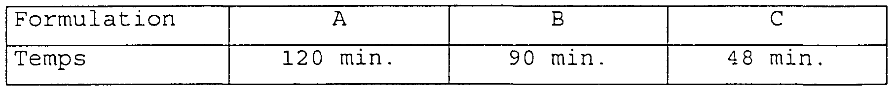
La formulation A est donc la plus performante.Formulation A is therefore the most efficient.
EXEMPLE II : Choix du fluidifiant par rapport à la microsilice .EXAMPLE II Choice of the fluidizer compared to the microsilica.
On prépare les formulations suivantes exprimées en % en poids par rapport au ciment :The following formulations, expressed in% by weight relative to the cement, are prepared:
- ciment Portland classe G: 100- Portland cement class G: 100
- silice (comme dans l'exemple 1) : 20- silica (as in Example 1): 20
- fluidifiant : 1,8 - eau totale : 27- fluidizer: 1.8 - total water: 27
- microsilice a : 24 Formulation A: fluidifiant D80 polynaphtalène sulfonate Formulation B: fluidifiant Styrène acrylate- microsilica a: 24 Formulation A: D80 polynaphthalene sulfonate thinner Formulation B: Styrene acrylate thinner
La viscosité est plus favorable avec le fluidifiant de la formulation A (fig. 2) .The viscosity is more favorable with the fluidizer of formulation A (fig. 2).
Le comportement de la formulation B est dû à des interactions spécifiques entre le fluidifiant fonctions acrylates et la microsilice provenant de l'industrie du zirconium. Il est donc préférable de formuler avec ce type de microsilice des fluidifiants contenant des fonctions sulfonés ou phosphatés et d'éviter les fonctions acrylate.The behavior of formulation B is due to specific interactions between the thinner acrylate functions and the microsilica from the zirconium industry. It is therefore preferable to formulate with this type of microsilica fluidizers containing sulfonated or phosphated functions and to avoid the acrylate functions.
EXEMPLE III : Optimisation du pourcentage en particules par rapport à des critères d'écoulement et de perte de charge pour la cimentation de puits.EXAMPLE III Optimization of the percentage of particles in relation to flow and pressure drop criteria for well cementing.
Le danger principal lors de la mise en place du laitier de ciment est la génération de pressions supérieures aux pressions de fracturation des roches traversées au cours du forage. Les pressions générées par l'injection de fluides en particulier de ciment au travers de la complétion d'un puits sont dues aux frottements. Pour ce type d'opération, un facteur important est le contrôle de l'écoulement du laitier de ciment et donc la connaissance de son comportement rhéologique. A partir d'un choix particulier de paramètres opérationnels, on déduit les pertes de charges et de pressions acceptables en tenant compte de la rhéologie du laitier de ciment.The main danger when placing the cement slag is the generation of pressures greater than the fracturing pressures of the rocks crossed during drilling. The pressures generated by the injection of fluids, in particular cement, through the completion of a well are due to friction. For this type of operation, an important factor is the control of the flow of the cement slag and therefore the knowledge of its rheological behavior. From a particular choice of operational parameters, the acceptable pressure and pressure losses are deduced, taking into account the rheology of the cement slag.
Le choix de la composition se fait par optimisation de la rhéologie à partir d'une certaine quantité d'eau fixée.The choice of composition is made by optimizing the rheology from a certain amount of fixed water.
On prépare les formulations suivantes exprimées en % par rapport au ciment : - Ciment Portland classe G : 100The following formulations, expressed in% relative to the cement, are prepared: - Portland cement class G: 100
- Silice (comme dans l'exemple 1)- Silica (as in Example 1)
- Fluidifiant (comme dans l'exemple 1) : 1,8- Fluidifier (as in Example 1): 1.8
- Eau totale : 27 - Microsilice a :- Total water: 27 - Microsilica has:
Formulation A : Microsilice a à 24% et silice à 20%Formulation A: Microsilica a at 24% and silica at 20%
Formulation Bl : Microsilice a à 30% et silice à 20%Formulation Bl: Microsilica a at 30% and silica at 20%
Formulation B2 : Microsilice a à 35% et silice à 20% Formulation Cl : Microsilice a à "24% et silice à 40%Formulation B2: Microsilica a at 35% and silica at 20% Formulation Cl: Microsilica a at " 24% and silica at 40%
Formulation C2 : Microsilice a à 24% et silice à 60%Formulation C2: Microsilica a at 24% and silica at 60%
Ces formulations ont fourni les résultats représentés sur la figure 3.These formulations provided the results shown in Figure 3.
Optimisation des particules fines : (A) en comparaison avec (Bl) et (B2) .Optimization of fine particles: (A) in comparison with (Bl) and (B2).
Plus la quantité de fines augmente, plus les particules peuvent s'écouler par un effet similaire à un roulement à billes et donc plus le laitier est fluide. Une limite en amélioration de viscosité est atteinte si on compare les courbes d'écoulement -Bl et B2. Un pourcentage optimal de fines, entre 20 et 35 %, est ainsi déterminé.The more the quantity of fines increases, the more the particles can flow through an effect similar to a ball bearing and therefore the more fluid the slag is. A limit in viscosity improvement is reached if we compare the flow curves -B1 and B2. An optimal percentage of fines, between 20 and 35%, is thus determined.
Optimisation des particules moyennes: (A) en comparaison avec (Cl) et (C2) .Optimization of average particles: (A) in comparison with (Cl) and (C2).
De même, le pourcentage relatif de particules moyennes par rapport à des particules fines est déterminé si on compare les courbes d'écoulement Cl et C2 par rapport à celle de A.Likewise, the relative percentage of average particles compared to fine particles is determined if we compare the flow curves Cl and C2 compared to that of A.
Les formulations Cl et C2 contiennent plus de particules moyennes par rapport aux particules fines (microsilice) , et présentent alors une rhéologie (courbes Cl et C2 de la figure 3) supérieure aux formulations Bl- B2, A, qui toutes trois ont une quantité de particules moyennes inférieure à celle des particules fines. Les laitiers de ciment ayant une rhéologie comparable à celle de Cl ou C2 , conviennent mal, ou même pas à la cimentation de puits pétroliers.Formulations Cl and C2 contain more medium particles compared to fine particles (microsilica), and then have a rheology (curves Cl and C2 in FIG. 3) greater than formulations Bl-B2, A, all of which have an amount of average particles lower than that of fine particles. The cement slags having a rheology comparable to that of Cl or C2, are ill-suited, or even not suitable for the cementing of oil wells.
En effet, cela est confirmé par un autre essai sur des formulations avec les quantités de silice et de microsilice rassemblées dans le tableau 3 ci-dessous. Les résultats de ces essais (τ en (Pa) ) sont également donnés dans le tableau 3.Indeed, this is confirmed by another test on formulations with the amounts of silica and microsilica collected in Table 3 below. The results of these tests (τ in (Pa)) are also given in Table 3.
TABLEAU 3TABLE 3

τ (Pa) représente les valeurs e contraintes mesurées pourτ (Pa) represents the values and stresses measured for
-1 un cisaillement donné de 100 Les formulation présentant des valeurs de contraintes inférieures à-1 a given shear of 100 Formulations with stress values less than
130 Pa sont obtenues pour des rapports microsilice/silice au plus égal à 1.130 Pa are obtained for microsilica / silica ratios at most equal to 1.
Dans le cas du taux relativement important deIn the case of the relatively high rate of
35 % de microsilice, un essai donne, pour 35 % de particules moyennes, une valeur de contrainte de l'ordre de 130 Pa qui représente une rhéologie parfois acceptable, mais généralement limite.35% microsilica, a test gives, for 35% of average particles, a stress value of the order of 130 Pa which represents a rheology which is sometimes acceptable, but generally limited.
Pour les formulation contenant 60 % de silice et entre 20 à 35 % de microsilice, les contraintes de cisaillement sont trop importantes pour l'application présente .For the formulation containing 60% of silica and between 20 to 35% of microsilica, the shear stresses are too great for the present application.
Pour une quantité de fines de l'ordre de 24%, une quantité en poids de particules moyennes de 20 % donne une bonne rhéologie pour une géométrie de puits classique .For an amount of fines of the order of 24%, an amount by weight of average particles of 20% gives good rheology for a well geometry classic.
De plus, la formulation A qui contient de l'eau dans un rapport eau sur ciment de 0,27 a une résistance à la compression 3,5 fois supérieure à une formulation classique de ciment pour puits qui contient de l'eau dans un rapport eau sur ciment supérieur à 0,4.In addition, formulation A which contains water in a water to cement ratio of 0.27 has a compressive strength 3.5 times greater than a conventional formulation of cement for wells which contains water in a ratio water on cement greater than 0.4.
EXEMPLE IV : Comparaison des propriétés d'une formulation de laitier de ciment classique avec une formulation selon la présente invention.EXAMPLE IV Comparison of the properties of a formulation of conventional cement slag with a formulation according to the present invention.
Les propriétés principales demandées pour un ciment pétrolier sont listées ci-dessous. Une comparaison systématique est réalisée entre la formulation de l'invention A et un ciment pétrolier (B) classique.The main properties required for petroleum cement are listed below. A systematic comparison is made between the formulation of invention A and a conventional petroleum cement (B).
Formulation A exprimée en % par rapport au cimentFormulation A expressed in% relative to the cement
- ciment (comme dans l'exemple 1) : 100- cement (as in Example 1): 100
- Silice (comme dans l'exemple 1) : 20 - fluidifiant D 80 (comme dans l'exemple 1) : 1,8- Silica (as in Example 1): 20 - D 80 thinner (as in Example 1): 1.8
- Eau totale : 27- Total water: 27
- microsilice a : 24 '- microsilica a: 24 '
- Retardateur D 121 (Do εll): 0,8 Formulation B exprimée en % par rapport au ciment - ciment (comme dans l'exemple 1)) : 100- Retarder D 121 (Do εll): 0.8 Formulation B expressed in% relative to the cement - cement (as in example 1)): 100
- Silice S8 ( Sifraco ) :40- Silica S8 (Sifraco): 40
- Filler Microblock (Halliburton): 14,3- Filler Microblock (Halliburton): 14.3
- Réducteur de filtrat Halad 361 A (Halliburton): 8,5- Halad 361 A filtrate reducer (Halliburton): 8.5
- Dispersant: CFR3 (Halliburton): 0,25 - Retardateur HR 15 (Halliburton) :0,7- Dispersant: CFR3 (Halliburton): 0.25 - HR 15 retarder (Halliburton): 0.7
- Eau totale :44%- Total water: 44%
La figure 4 montre une courbe de viscosité plus faible pour la formulation (A), ce qui limite d'autant plus les pertes de charges dans le puits . La résistance à la compression, le temps de pompabilité, c'est à dire le temps nécessaire à la mise en place du laitier dans le puits et à la solidification du laitier, et la densité optimisée pour contrôler la pression lors de la mise en place en partielle dans les cas de puits chaud et profond, sont rapportés dans le tableau 4 ci-après. Ce tableau confirme la performance du laitier de ciment à base d'une formulation A notamment pour la cimentation de puits chaud et profond.Figure 4 shows a lower viscosity curve for formulation (A), which further limits the pressure drops in the well. The compressive strength, the time of pumpability, that is to say the time necessary for the establishment of the slag in the well and for the solidification of the slag, and the density optimized to control the pressure during the partial establishment in the case of hot wells and deep, are reported in Table 4 below. This table confirms the performance of the cement slag based on formulation A, in particular for the cementing of hot and deep wells.
TABLEAU 4TABLE 4
Claims
Priority Applications (6)
| Application Number | Priority Date | Filing Date | Title |
|---|---|---|---|
| DK98954501T DK0950034T3 (en) | 1997-11-03 | 1998-11-02 | Cement blend for cementing a wellbore especially an oil well |
| US09/341,097 US6332920B1 (en) | 1997-11-03 | 1998-11-02 | Slag for cementing a well, in particular an oil well |
| CA 2276714 CA2276714C (en) | 1997-11-03 | 1998-11-02 | Slag for cementing a well, in particular an oil well |
| DE69804198T DE69804198T2 (en) | 1997-11-03 | 1998-11-02 | CEMENT SLUDGE FOR THE CEMENTING OF HOLES, IN PARTICULAR OIL HOLES |
| EP98954501A EP0950034B1 (en) | 1997-11-03 | 1998-11-02 | Slag for cementing a well, in particular an oil well |
| NO19993132A NO325917B1 (en) | 1997-11-03 | 1999-06-23 | Cement slag for a well, especially an oil well |
Applications Claiming Priority (2)
| Application Number | Priority Date | Filing Date | Title |
|---|---|---|---|
| FR9713796A FR2770517B1 (en) | 1997-11-03 | 1997-11-03 | WELL CEMENTING DAIRY, ESPECIALLY AN OIL WELL |
| FR97/13796 | 1997-11-03 |
Publications (1)
| Publication Number | Publication Date |
|---|---|
| WO1999023046A1 true WO1999023046A1 (en) | 1999-05-14 |
Family
ID=9512974
Family Applications (1)
| Application Number | Title | Priority Date | Filing Date |
|---|---|---|---|
| PCT/FR1998/002339 Ceased WO1999023046A1 (en) | 1997-11-03 | 1998-11-02 | Slag for cementing a well, in particular an oil well |
Country Status (8)
| Country | Link |
|---|---|
| US (1) | US6332920B1 (en) |
| EP (1) | EP0950034B1 (en) |
| CA (1) | CA2276714C (en) |
| DE (1) | DE69804198T2 (en) |
| DK (1) | DK0950034T3 (en) |
| FR (1) | FR2770517B1 (en) |
| NO (1) | NO325917B1 (en) |
| WO (1) | WO1999023046A1 (en) |
Cited By (11)
| Publication number | Priority date | Publication date | Assignee | Title |
|---|---|---|---|---|
| WO2000061914A1 (en) | 1999-04-09 | 2000-10-19 | Shell Internationale Research Maatschappij B.V. | Method for annular sealing |
| FR2815029A1 (en) | 2000-10-09 | 2002-04-12 | Inst Francais Du Petrole | CEMENT DAIRY ALLEGES |
| FR2859993A1 (en) * | 2003-09-24 | 2005-03-25 | Inst Francais Du Petrole | High performance cement slag with good chemical stability for use in underground applications for hydrocarbon and geothermal reservoirs |
| US7004260B2 (en) | 2001-07-18 | 2006-02-28 | Shell Oil Company | Method of sealing an annulus |
| WO2010130927A1 (en) | 2009-05-11 | 2010-11-18 | Lafarge | Moulding device and production method |
| US7901615B2 (en) | 2006-11-08 | 2011-03-08 | Lafarge | Moulding device and production process |
| WO2011095744A2 (en) | 2010-02-04 | 2011-08-11 | Lafarge | Concrete element having a superhydrophobic surface |
| US8043425B2 (en) | 2006-05-17 | 2011-10-25 | Lafarge | Concrete with a low cement content |
| WO2012020012A1 (en) | 2010-08-11 | 2012-02-16 | Lafarge | Concrete article comprising a surface with low open-porosity |
| US8177930B2 (en) | 2006-12-21 | 2012-05-15 | Lafarge | Process of production and structural element |
| CN102197021B (en) * | 2008-10-22 | 2014-09-24 | 中央硝子株式会社 | Method for producing fluorosulfuric acid ester |
Families Citing this family (9)
| Publication number | Priority date | Publication date | Assignee | Title |
|---|---|---|---|---|
| GB2362881B (en) * | 1998-11-13 | 2002-08-14 | Sofitech | A cementing composition and application to cementing oil wells or the like |
| US6610224B2 (en) * | 2001-02-22 | 2003-08-26 | Sullivan Concrete Textures | Processes for producing monolithic architectural cementitious structures having decorative aggregate-containing cementitious surfaces |
| US7156174B2 (en) | 2004-01-30 | 2007-01-02 | Halliburton Energy Services, Inc. | Contained micro-particles for use in well bore operations |
| FR2875802B1 (en) * | 2004-09-29 | 2006-12-29 | Inst Francais Du Petrole | CEMENT MATERIAL OF A WELL |
| FR2875801B1 (en) * | 2004-09-29 | 2007-06-08 | Inst Francais Du Petrole | GROUT CEMENT-FOAM |
| US8456360B2 (en) | 2005-08-11 | 2013-06-04 | Sierra Nevada Corporation | Beam-forming antenna with amplitude-controlled antenna elements |
| US20070227728A1 (en) * | 2006-03-30 | 2007-10-04 | Chambers Don E | Method and lightweight composition for sealing pipe and wellbores |
| US9512351B2 (en) | 2007-05-10 | 2016-12-06 | Halliburton Energy Services, Inc. | Well treatment fluids and methods utilizing nano-particles |
| US20120041087A1 (en) * | 2010-08-12 | 2012-02-16 | Evgeniy Nikolaevich Yastremskiy | Dry mixture for manufacturing cellular fibro concrete and method thereof |
Citations (5)
| Publication number | Priority date | Publication date | Assignee | Title |
|---|---|---|---|---|
| US4501830A (en) * | 1984-01-05 | 1985-02-26 | Research One Limited Partnership | Rapid set lightweight cement product |
| US4935060A (en) * | 1987-11-16 | 1990-06-19 | Elkem A/S | Hydraulic cement slurry |
| WO1990011977A1 (en) * | 1989-04-10 | 1990-10-18 | Den Norske Stats Oljeselskap A.S | Procedure for the admixture of silicon oxide to a hydraulic cement slurry |
| EP0518777A1 (en) * | 1991-06-12 | 1992-12-16 | Bouygues | High-performance mortar, concretes obtained from this mortar and the elements produced from this mortar or concrete |
| US5531823A (en) * | 1995-02-06 | 1996-07-02 | Atomic Energy Of Canada Limited | Low-heat high-performance concrete |
Family Cites Families (11)
| Publication number | Priority date | Publication date | Assignee | Title |
|---|---|---|---|---|
| NO153566B (en) * | 1982-12-07 | 1986-01-06 | Elkem As | ADDITIONAL MIXTURE FOR CONCRETE AND MORTAL, PROCEDURE FOR PREPARING THE MIXTURE, AND USE THEREOF. |
| US5073197A (en) * | 1988-08-12 | 1991-12-17 | National Research Development Corporation | Cement compositions |
| JPH04104926A (en) * | 1990-08-20 | 1992-04-07 | Daikyo Inc | Composition for producing building material block |
| US5125455A (en) * | 1991-01-08 | 1992-06-30 | Halliburton Services | Primary cementing |
| FR2673620B1 (en) * | 1991-03-04 | 1994-04-08 | Dowell Schlumberger Cie Services | COMPOSITION FOR CEMENTING LOW TEMPERATURE OIL WELLS. |
| DE4118991C2 (en) * | 1991-06-08 | 1997-09-11 | Werkzeug Gmbh | Drilling jig for the formation of certain drill hole patterns on workpieces |
| FR2707977B1 (en) * | 1993-07-01 | 1996-01-12 | Bouygues Sa | Method and composition for manufacturing concrete elements having remarkable compressive strength and fracturing energy and elements thus obtained. |
| US5769939A (en) * | 1993-12-07 | 1998-06-23 | Elkem Asa | Cement based injection grout |
| US5968257A (en) * | 1994-08-29 | 1999-10-19 | Sandia Corporation | Ultrafine cementitious grout |
| US5795924A (en) * | 1996-07-01 | 1998-08-18 | Halliburton Company | Resilient well cement compositions and methods |
| US5976240A (en) * | 1997-09-08 | 1999-11-02 | North American Refractories Co. | Refractory system including reactive metakaolin additive |
-
1997
- 1997-11-03 FR FR9713796A patent/FR2770517B1/en not_active Expired - Fee Related
-
1998
- 1998-11-02 EP EP98954501A patent/EP0950034B1/en not_active Expired - Lifetime
- 1998-11-02 DE DE69804198T patent/DE69804198T2/en not_active Expired - Lifetime
- 1998-11-02 US US09/341,097 patent/US6332920B1/en not_active Expired - Lifetime
- 1998-11-02 DK DK98954501T patent/DK0950034T3/en active
- 1998-11-02 CA CA 2276714 patent/CA2276714C/en not_active Expired - Fee Related
- 1998-11-02 WO PCT/FR1998/002339 patent/WO1999023046A1/en not_active Ceased
-
1999
- 1999-06-23 NO NO19993132A patent/NO325917B1/en not_active IP Right Cessation
Patent Citations (5)
| Publication number | Priority date | Publication date | Assignee | Title |
|---|---|---|---|---|
| US4501830A (en) * | 1984-01-05 | 1985-02-26 | Research One Limited Partnership | Rapid set lightweight cement product |
| US4935060A (en) * | 1987-11-16 | 1990-06-19 | Elkem A/S | Hydraulic cement slurry |
| WO1990011977A1 (en) * | 1989-04-10 | 1990-10-18 | Den Norske Stats Oljeselskap A.S | Procedure for the admixture of silicon oxide to a hydraulic cement slurry |
| EP0518777A1 (en) * | 1991-06-12 | 1992-12-16 | Bouygues | High-performance mortar, concretes obtained from this mortar and the elements produced from this mortar or concrete |
| US5531823A (en) * | 1995-02-06 | 1996-07-02 | Atomic Energy Of Canada Limited | Low-heat high-performance concrete |
Non-Patent Citations (2)
| Title |
|---|
| DILLENBECK R L ET AL: "THE EFFECT OF MICROSILICA ON THE THERMAL STABILITY OF LIGHTWEIGHT CEMENT SYSTEMS", ANNUAL SPE/CIM PETROL SOC. HORIZ. WELLS CONFERENCE, no. 116, 1990, pages 1 - 5, XP002044825 * |
| NELSON E B: "PORTLAND CEMENTS CHARACTERIZED, EVALUATED", OIL AND GAS JOURNAL, vol. 81, no. 5, 7 February 1983 (1983-02-07), pages 73 - 77, XP000142872 * |
Cited By (16)
| Publication number | Priority date | Publication date | Assignee | Title |
|---|---|---|---|---|
| US6431282B1 (en) | 1999-04-09 | 2002-08-13 | Shell Oil Company | Method for annular sealing |
| WO2000061914A1 (en) | 1999-04-09 | 2000-10-19 | Shell Internationale Research Maatschappij B.V. | Method for annular sealing |
| FR2815029A1 (en) | 2000-10-09 | 2002-04-12 | Inst Francais Du Petrole | CEMENT DAIRY ALLEGES |
| US6656263B2 (en) | 2000-10-09 | 2003-12-02 | Institute Francais Du Petrole | Lightened cement slurries |
| US7004260B2 (en) | 2001-07-18 | 2006-02-28 | Shell Oil Company | Method of sealing an annulus |
| FR2859993A1 (en) * | 2003-09-24 | 2005-03-25 | Inst Francais Du Petrole | High performance cement slag with good chemical stability for use in underground applications for hydrocarbon and geothermal reservoirs |
| WO2005031114A1 (en) | 2003-09-24 | 2005-04-07 | Institut Francais Du Petrole | Oil-well cement slurry |
| US7540915B2 (en) | 2003-09-24 | 2009-06-02 | Institut Francais Du Petrole | Oil-well cement slurry |
| US8043425B2 (en) | 2006-05-17 | 2011-10-25 | Lafarge | Concrete with a low cement content |
| US7901615B2 (en) | 2006-11-08 | 2011-03-08 | Lafarge | Moulding device and production process |
| US8177930B2 (en) | 2006-12-21 | 2012-05-15 | Lafarge | Process of production and structural element |
| CN102197021B (en) * | 2008-10-22 | 2014-09-24 | 中央硝子株式会社 | Method for producing fluorosulfuric acid ester |
| WO2010130927A1 (en) | 2009-05-11 | 2010-11-18 | Lafarge | Moulding device and production method |
| US9914242B2 (en) | 2009-05-11 | 2018-03-13 | Lafarge | Moulding device and production process |
| WO2011095744A2 (en) | 2010-02-04 | 2011-08-11 | Lafarge | Concrete element having a superhydrophobic surface |
| WO2012020012A1 (en) | 2010-08-11 | 2012-02-16 | Lafarge | Concrete article comprising a surface with low open-porosity |
Also Published As
| Publication number | Publication date |
|---|---|
| DE69804198D1 (en) | 2002-04-18 |
| NO993132L (en) | 1999-08-30 |
| CA2276714C (en) | 2008-05-27 |
| FR2770517B1 (en) | 1999-12-03 |
| DE69804198T2 (en) | 2002-10-02 |
| EP0950034B1 (en) | 2002-03-13 |
| DK0950034T3 (en) | 2002-06-10 |
| CA2276714A1 (en) | 1999-05-14 |
| NO325917B1 (en) | 2008-08-18 |
| FR2770517A1 (en) | 1999-05-07 |
| EP0950034A1 (en) | 1999-10-20 |
| US6332920B1 (en) | 2001-12-25 |
| NO993132D0 (en) | 1999-06-23 |
Similar Documents
| Publication | Publication Date | Title |
|---|---|---|
| EP0950034B1 (en) | Slag for cementing a well, in particular an oil well | |
| USRE32742E (en) | Method of producing light weight cement for use of cementation of oil and gas wells | |
| FR2749844A1 (en) | New cementation compositions of aluminous cement, dispersant and setting accelerator additives | |
| US7217441B2 (en) | Methods for coating pipe comprising using cement compositions comprising high tensile strength fibers and/or a multi-purpose cement additive | |
| CN1058316C (en) | Drilling and cementing a well | |
| RU2078741C1 (en) | Method of preparing hydraulic cement composition | |
| US7238733B2 (en) | Storable water-silica suspensions and methods | |
| CN111018410B (en) | Cement paste system and preparation method thereof | |
| FR2704218A1 (en) | Milk cements, their preparation and their use in cementing wells. | |
| WO2000029351A1 (en) | Cementation product and use for cementing oil wells or the like | |
| CN1291964A (en) | General oil well cement admixture and method | |
| CN106966648A (en) | A kind of anti-CO2、H2S corrodes cementing slurry | |
| CN115043621A (en) | High-density cement slurry resistant to high temperature and carbon dioxide corrosion and preparation method and application thereof | |
| EP0458852A1 (en) | Thinned cement slurry for use in the cementation of wells for producing hydrocarbons | |
| FR2882050A1 (en) | CEMENT MATERIAL COMPRISING PARTICLES OF POLYMERS, METHOD FOR TREATING PARTICLES, AND CEMENT LAYER | |
| EP2401241A1 (en) | Dry composition comprising a binder and a silicone oil | |
| EP1671012A1 (en) | Oil-well cement slurry | |
| CN118255568A (en) | Fluidized solidified soil and preparation method thereof | |
| AU2007295181B2 (en) | Method of cementing gas or oil pipeline and hydraulic cement slurry | |
| FR2749843A1 (en) | New cementation compositions useful for the support of drilling tubes in the drilling of petroleum wells | |
| JP4490796B2 (en) | Low thermal resistance slurry material for underground power transmission | |
| CN112441778A (en) | Cement slurry composition, cement slurry for well cementation and preparation method and application thereof | |
| CN111003998B (en) | Non-ignition self-compacting concrete and preparation method thereof | |
| JP3198643B2 (en) | Water loss prevention cement composition | |
| EP4161883A1 (en) | Grout for the injection of prestressing cables and method for installing a cable comprising such a grout |
Legal Events
| Date | Code | Title | Description |
|---|---|---|---|
| AK | Designated states |
Kind code of ref document: A1 Designated state(s): CA NO US |
|
| AL | Designated countries for regional patents |
Kind code of ref document: A1 Designated state(s): AT BE CH CY DE DK ES FI FR GB GR IE IT LU MC NL PT SE |
|
| WWE | Wipo information: entry into national phase |
Ref document number: 1998954501 Country of ref document: EP |
|
| ENP | Entry into the national phase |
Ref document number: 2276714 Country of ref document: CA Ref country code: CA Ref document number: 2276714 Kind code of ref document: A Format of ref document f/p: F |
|
| 121 | Ep: the epo has been informed by wipo that ep was designated in this application | ||
| WWE | Wipo information: entry into national phase |
Ref document number: 09341097 Country of ref document: US |
|
| WWP | Wipo information: published in national office |
Ref document number: 1998954501 Country of ref document: EP |
|
| WWG | Wipo information: grant in national office |
Ref document number: 1998954501 Country of ref document: EP |