WO1998017943A1 - Integrated beamformer and methods of manufacture thereof - Google Patents
Integrated beamformer and methods of manufacture thereof Download PDFInfo
- Publication number
- WO1998017943A1 WO1998017943A1 PCT/US1997/019500 US9719500W WO9817943A1 WO 1998017943 A1 WO1998017943 A1 WO 1998017943A1 US 9719500 W US9719500 W US 9719500W WO 9817943 A1 WO9817943 A1 WO 9817943A1
- Authority
- WO
- WIPO (PCT)
- Prior art keywords
- refractive
- diffuser
- distal
- providing
- surface diffuser
- Prior art date
- Legal status (The legal status is an assumption and is not a legal conclusion. Google has not performed a legal analysis and makes no representation as to the accuracy of the status listed.)
- Ceased
Links
Classifications
-
- G—PHYSICS
- G02—OPTICS
- G02B—OPTICAL ELEMENTS, SYSTEMS OR APPARATUS
- G02B5/00—Optical elements other than lenses
- G02B5/02—Diffusing elements; Afocal elements
- G02B5/0205—Diffusing elements; Afocal elements characterised by the diffusing properties
- G02B5/0252—Diffusing elements; Afocal elements characterised by the diffusing properties using holographic or diffractive means
-
- G—PHYSICS
- G02—OPTICS
- G02B—OPTICAL ELEMENTS, SYSTEMS OR APPARATUS
- G02B19/00—Condensers, e.g. light collectors or similar non-imaging optics
- G02B19/0004—Condensers, e.g. light collectors or similar non-imaging optics characterised by the optical means employed
- G02B19/0028—Condensers, e.g. light collectors or similar non-imaging optics characterised by the optical means employed refractive and reflective surfaces, e.g. non-imaging catadioptric systems
-
- G—PHYSICS
- G02—OPTICS
- G02B—OPTICAL ELEMENTS, SYSTEMS OR APPARATUS
- G02B19/00—Condensers, e.g. light collectors or similar non-imaging optics
- G02B19/0033—Condensers, e.g. light collectors or similar non-imaging optics characterised by the use
- G02B19/0047—Condensers, e.g. light collectors or similar non-imaging optics characterised by the use for use with a light source
-
- G—PHYSICS
- G02—OPTICS
- G02B—OPTICAL ELEMENTS, SYSTEMS OR APPARATUS
- G02B5/00—Optical elements other than lenses
- G02B5/02—Diffusing elements; Afocal elements
- G02B5/0268—Diffusing elements; Afocal elements characterized by the fabrication or manufacturing method
-
- G—PHYSICS
- G02—OPTICS
- G02B—OPTICAL ELEMENTS, SYSTEMS OR APPARATUS
- G02B6/00—Light guides; Structural details of arrangements comprising light guides and other optical elements, e.g. couplings
- G02B6/10—Light guides; Structural details of arrangements comprising light guides and other optical elements, e.g. couplings of the optical waveguide type
- G02B6/12—Light guides; Structural details of arrangements comprising light guides and other optical elements, e.g. couplings of the optical waveguide type of the integrated circuit kind
- G02B6/122—Basic optical elements, e.g. light-guiding paths
- G02B6/1221—Basic optical elements, e.g. light-guiding paths made from organic materials
-
- G—PHYSICS
- G02—OPTICS
- G02B—OPTICAL ELEMENTS, SYSTEMS OR APPARATUS
- G02B6/00—Light guides; Structural details of arrangements comprising light guides and other optical elements, e.g. couplings
- G02B6/24—Coupling light guides
- G02B6/241—Light guide terminations
-
- G—PHYSICS
- G02—OPTICS
- G02B—OPTICAL ELEMENTS, SYSTEMS OR APPARATUS
- G02B6/00—Light guides; Structural details of arrangements comprising light guides and other optical elements, e.g. couplings
- G02B6/24—Coupling light guides
- G02B6/26—Optical coupling means
- G02B6/32—Optical coupling means having lens focusing means positioned between opposed fibre ends
-
- G—PHYSICS
- G02—OPTICS
- G02B—OPTICAL ELEMENTS, SYSTEMS OR APPARATUS
- G02B6/00—Light guides; Structural details of arrangements comprising light guides and other optical elements, e.g. couplings
- G02B6/0001—Light guides; Structural details of arrangements comprising light guides and other optical elements, e.g. couplings specially adapted for lighting devices or systems
Definitions
- the present invention relates in general to the field of lighting. More particularly, the present invention relates to beamformers for remote source lighting. Specifically, a preferred embodiment of the present invention relates to a solid integrated beamformer having a surface diffuser. The present invention thus relates to beamformers of the type that can be termed integrated.
- RSL remote source lighting
- NEO Nonimaging optics
- nonimaging optics The principal area of development of nonimaging optics since then has been in the concentration of solar energy for heating and photovoltaic power conversion (5 6) .
- Other applications of nonimaging optics have included infrared communications receivers, fiber optic coupling and luminescent concentrators for integrated devices (7 9) .
- Nonimaging optics have also been extended to include tapered optical fibers for fiber optic sensors (10"13) .
- Recent progress in i) developing efficient light sources and ii) manufacturing optical fiber has permitted the assembly of an RSL system in which one, or more, optical fibers are used to deliver light to one, or more, remotely located points. The distal end of each optical fiber can be used for illumination directly or in conjunction with refractive lenses, to approximate the light distribution required by a given application.
- the cleaved open end of a plastic optical fiber produces a light cone with a solid angle of from 50° to 80° , depending on the core and cladding materials of the fiber.
- a separate refractive lens can be located near such an end.
- using a lens to shape light from the end has caused problems of light loss and overly complicated lens designs. Therefore, the previous RSL systems are limited to end uses where a highly precise illuminance distribution is not required.
- the above-discovered problems have ruled out such RSL applications as navigation lighting, obstruction lighting, signal lighting and airport approach lighting.
- 08/636,798 discloses a universal remote lighting system.
- U.S. Pat. No. 5,365,354 discloses method of making a grated refractive index type diffuser based on volume holographic material.
- U.S. Pat. No. 5,534,386 discloses a homogenizer formed using coherent light and a holographic diffuser.
- the present invention is directed to a solid integrated beamformer that combines nonimaging optics, refractive optics and a surface diffuser for shaping light.
- the present invention is also directed to methods of manufacturing the integrated beamformer.
- An effect of the present invention is to reduce the size and weight of the assembly, as well as its complexity, by joining together the diffuser, refractive optics and nonimaging optics in a single unitary device.
- the advantages of the present invention include fewer parts combined with a reduction in size and/or weight and a reduction in cost. These advantages will be appreciated in both military and commercial lighting applications.
- the benefits of a shipboard navigation lighting system according to the present invention include: the elimination of the need for a separate diffuser mounting bracket, a corresponding reduction in the size and mass of the enclosure; and a corresponding reduction in topside weight and moment.
- an RSL system according to the present invention may require less maintenance and have a longer useful life.
- a primary object of the invention is to provide an apparatus that combines nonimaging optics, refractive optics and a surface diffuser into a single unitary component. Another object of the invention is to provide an apparatus that is cost effective. It is another object of the invention is to provide an apparatus that is rugged and reliable, thereby decreasing down time and operating costs. It is yet another object of the invention is to provide an apparatus that has one or more of the characteristics discussed above but which is relatively simple to manufacture and assemble using a minimum of equipment.
- a solid integrated beamformer including: a solid nonimaging optic having i) a proximal nonimaging end and ii) a distal nonimaging end; a solid refractive optic integrally attached to said distal nonimaging end, said solid refractive optic including a distal refractive end; and a surface diffuser integrally formed on said distal refractive end.
- the invention also includes apparatus that incorporates the solid integrated beamformer.
- Another object of the invention is to provide methods that can be used to manufacture the integrated beamformer. It is another object of the invention is to provide methods that are predictable and reproducible, thereby decreasing variance and operating costs. It is yet another object of the invention is to provide methods that have one or more of the characteristics discussed above but which are relatively simple to setup and operate using moderately skilled workers.
- these objects are achieved by providing a method comprising: providing an optical blank with a nonimaging optic and a refractive optic, said refractive optic having a distal refractive surface; providing a surface diffuser master; contacting said distal refractive surface with said diffuser master; and removing said diffuser master from said distal refractive surface so as to replicate said surface diffuser master.
- the invention also includes apparatus for carrying out the replication of the surface diffuser on the distal refractive surface, or alternatively, molding, or casting the surface diffuser so as to integrally form the surface diffuser.
- FIG. 1 illustrates a schematic view of a beamformer
- FIG. 2(a) illustrates an isometric view of a solid integrated beamformer according to the present invention
- FIG. 2(b) illustrates a micrographic view of a submicron holographic diffuser surface relief embossed on a spherical surface lens of the solid integrated beamformer depicted in FIG. 2(a);
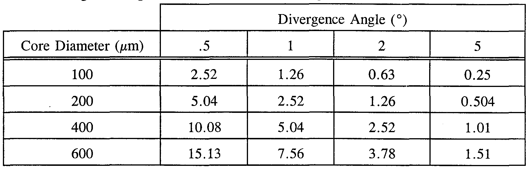
- FIG. 3(a) illustrates light transformer diameter according to the present invention as a function of divergence angle for several common fiber diameters
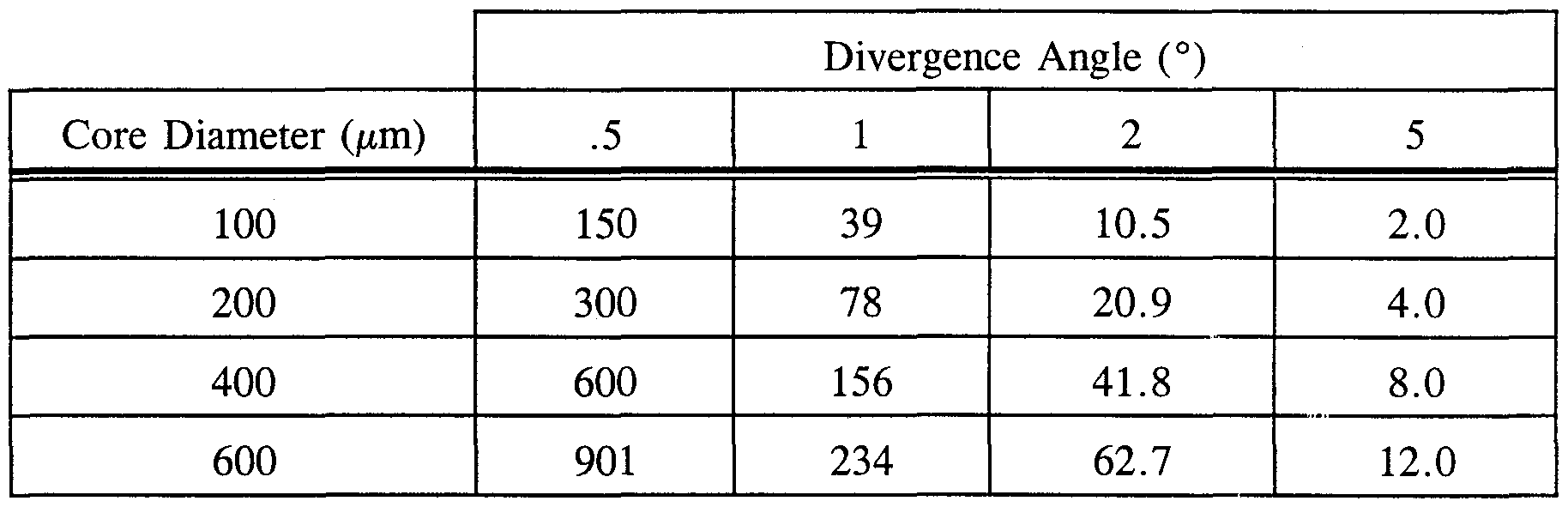
- FIG. 3(b) illustrates light transformer length according to the present invention as a function of divergence angle for several common fiber diameters
- FIG. 4(a) illustrates relative intensity of light transmitted by optical fiber as a function of divergence angle for two common fiber numerical apertures
- FIG. 4(b) illustrates total intensity of light transmitted by optical fiber as a function of divergence angle for two common fiber numerical apertures
- FIG. 5 illustrates a schematic view of the surface contour of a compound parabolic concentrator according to the present invention
- FIG. 6 illustrates a schematic view of the reflection geometry for a compound parabolic concentrator conical section according to the present invention
- FIG. 7 illustrates a schematic polar coordinate system used to calculate a compound parabolic concentrator parabolic curve according to the present invention
- FIG. 8 illustrates a geometric construction used to derive Eq. (7) according to the present invention
- FIG. 9 illustrates a schematic of a general surface contour for a nonimaging optic/lens combination according to the present invention
- FIG. 10(a) illustrates isometric 3-D display of the performance of an elliptical non-Lambertian holographic surface diffuser according to the present invention
- FIG. 10(b) illustrates a pattern photo from the diffuser used to generate the performance data illustrated in FIG. 10(a);
- FIG. 11(a) illustrates a microphotograph of a holographic surface relief from a circular non-Lambertian holographic surface diffuser according to the present invention
- FIG. 11(b) illustrates a microphotograph of a holographic surface relief of an elliptical non-Lambertian holographic surface diffuser according to the present invention
- FIG. 12 illustrates a perspective view of a non-Lambertian holographic surface diffuser recording geometry using a rectangular diffuser aperture according to the present invention
- FIG. 13 illustrates the reading geometry for a beam scattered by non- Lambertian holographic surface diffuser according to the present invention
- FIGS. 14(a)-(g) illustrates a nickel electroforming technique sequence for submicron surface relief replication of a non-Lambertian holographic surface diffuser according to the present invention.
- FIG. 15 illustrates a schematic view of an automatic light scattering apparatus for the characterization of nonimaging optics/holographic surface diffuser combinations according to the present invention.
- the present invention includes several alternative processing approaches that will result in the fabrication of a solid integrated beamformer with a holographic microstructure replicated on its surface.
- the present invention is a surface diffuser formed on refractive optics. It should be noted that the features illustrated in the drawings are not necessarily drawn to scale.
- a nonintegrated distal end device to provide high- definition remote source lighting can consist of three separate components. These three discrete optical parts include: a non- imaging light transformer to reduce the divergence angle of the light emerging from an optical fiber; a spherical convex lens to reduce the physical size of the device; and a non- Lambertian holographic diffuser to shape the light into the desired pattern.
- the beamformer assembly consists of three major elements: the optical connector, enclosure, and some support hardware. Depending on the holographic recording conditions, the diffuser can shape the outgoing light into circular, elliptical, linear, or even square patterns with a wide range of angular distributions (from 1 ° to 100°) along both axes, independently.
- Nonimaging light transformer 40 is connected to optical fiber 20 within optical connector 30. Light travels into nonimaging light transformer 40 from optical fiber 20 across the interface between these two components.
- Spherical convex lens 50 is connected to nonimaging light transformer 40.
- a non-Lambertian holographic diffuser 60 is located downstream of spherical convex lens 50. The non-Lambertian holographic diffuser 60, the spherical convex lens 50 and most of nonimaging light transformer 40 are assembled within enclosure 70.
- the losses due to Fresnel reflection may be as high as 16% because of the number of surfaces.
- Third, the overall cost of the resulting beamformer is driven up by the expensive, necessarily labor intensive, assembly of the separate components. What is needed, therefore, is the combination of fiber optic/NIO/lens/diffuser through the full integration of the NIO/lens/diffuser components.
- the present invention is directed to this approach, thereby permitting the optimization of the efficiency of the optical system together with streamlined design and more cost effective production of the beamformer.
- the solid integrated beamformer has up to a 20% improvement in efficiency and vastly reduced manufacturing costs.
- the approach represented by the present invention is to integrate three previously separate and discrete beamformer components (the light transformer, the lens, and the diffuser) into one solid integrated beamformer (SIB) optical element. In order to achieve this result, several techniques for submicron surface relief replication on a curved surface are discussed below.
- a solid integrated beamformer 80 is depicted.
- the solid integrated beamformer (SIB) includes a sophisticated combination of parabolic and hyperbolic surfaces for a non-imaging light transformer integrated with a convex lens 90 in a molded body 100.
- a submicron holographic diffuser surface relief shown at magnification xlOOO
- the surface of the lens can be aspherical, provided that the shapes of the other surfaces are correspondingly modified.
- HD RSL High Definition Remote Source Lighting
- the resulting distal end optical device i.e. , a solid integrated beamformer with much higher efficiency
- Such a beamformer will make it possible to implement remote source lighting for high-definition lighting.
- Remote source lighting has a number of benefits: ease and low cost of handling, maintenance, and repair of conveniently located light sources; reduced electrical power consumption; major reduction in life-cycle costs; high reliability and redundancy; reduced EMI/EMP vulnerability; and heat removal from the lighting point.
- the present invention provides the unexpected results of both an improvement in performance and a significant reduction in the cost of production of the beamformer.
- Transmission characteristics for each of the solid integrated beamformer components, as well as integrated components, can be calculated and/or measured one at a time without undue experimentation using apparatus that is disclosed below.
- a and a are the areas of the optical beam
- ⁇ and 0 2 are the divergence angles of the beam at any two points along its propagation path.
- a and a are the areas of the optical beam
- ⁇ and 0 2 are the divergence angles of the beam at any two points along its propagation path.
- a and a are the areas of the optical beam
- ⁇ and 0 2 are the divergence angles of the beam at any two points along its propagation path.
- FIGS. 4(a) and 4(b) For numerical apertures (NAs) of 0.22 (13 ° ) and 0.035 (2°).
- the NA is defined as the angle which contains 95 % of the light intensity.
- An NA of 0.22 is typical of a multimode fused silica fiber. This NA of 0.22 is assumed in much of the discussion that follows, but the same arguments may be extended to borosilicate and plastic fibers that have NAs near 0.5, (corresponding to a half angle of 30°). From FIGS. 4(a) and 4(b) it will be appreciated that, even for an NA of 0.035 (2°), over 60 % of the light is concentrated within the first 0.5 ° . b.
- the apertures and lengths of NIOs for 100, 200, 400, 600, and 1000 ⁇ m core diameters for divergence angles of 0.5°, 1 °, 2° and 5° calculated from Eqs. (1) and (2) are given in Tables 1(a) and
- the basic surface contour used in non-imaging optics is that of a parabola (1) .
- a combination of a lens and a modified (hyperbolic/parabolic) surface contour can be used to reduce the length of the LT.
- a simple conical surface can be substituted for the hyperbola/parabola contour with minimal loss in collection efficiency.
- the basic surface contour is that of a compound parabolic concentrator.
- CPC compound parabolic concentrator
- LT light transformer
- Optical fiber 120 is connected to conical optical element 145.
- Conical optical element 145 composes part of nonimaging optic 140.
- a CPC is made up of a parabolic section and a straight section rotated around the axis of symmetry of the optical element to form a paraboloid coupled to a straight-sided cone.
- the parabola's axis is aligned not with the axis of symmetry, but along the design's maximum acceptance angle q
- a conical optical element is introduced at the fiber end of the LT.
- the conical optical element can be an integral part of the NIO. In a one-dimensional cross section, this cone performs as a plane mirror that turns incident light at the maximum acceptance angle so that it is incident on the fiber face at 13°. For a 1 ° LT input acceptance angle, the cone half angle is 6°.
- the length of the straight-sided section can be determined directly from the reflection geometry.
- I d/(tan(13°) - tan( ⁇ )), (4) where d is the fiber diameter and ⁇ the half angle of the cone formed by the straight section. For a 1 ° acceptance angle and a 400 ⁇ m diameter core fiber with a numerical aperture of 0.22, ⁇ is 6°, I is 3.18 mm, and the LT diameter at this point is 1.06 mm.
- the determination of the parabolic contour requires a straightforward rotation and translation of the basic parabolic equation.
- the transformation is simplified if the polar coordinates defined in FIG. 7 are used.
- a polar coordinate system used to calculate the CPC parabolic curve is depicted.
- r 2f sin ( ⁇ - 0 max )/(l - cos ⁇ ) - a;
- z 2f cos ( ⁇ - 0 max )/(l- cos ⁇ ), (6)
- Eq. (7) is derived from the basic geometrical definition of the parabola: a collection of points equidistant from a fixed point and a line. Referring to FIG. 8, the geometric construction used to derive Eq. (7) is depicted.
- the general surface contour for an LT/lens combination is a combination of a hyperbola, a parabola, and a spherical lens.
- Optical fiber 220 is connected to nonimaging optics 240.
- Refractive optics 250 are connected to nonimaging optics 240.
- nonimaging optics 240 and refractive optics 250 compose a solid integrated beamformer. At the maximum design divergence angle, the focal points of the lens, the parabola, and the first focus of the hyperbola are coincident.
- the present invention uses a holographic surface diffuser.
- This method of light-beam shaping utilizes a holographically recorded diffuser with a random nonperiodic surface microstructure.
- This recording and processing technology allows a wide range of holographic non-Lambertian diffusers to be produced.
- These diffusers shape the beam by precisely controlling the light intensity spatial distribution.
- Various light patterns - circular, elliptical, linear, even square and rectangular with light distribution from 100 ° to 1 ° or less along the horizontal and vertical axes — can be formed.
- FIGS. 10(a) and 10(b) elliptical non-Lambertian holographic diffuser performance is depicted.
- FIG. 10(a) is a computer-generated output profile; and
- FIG. 10(b) is a pattern photo.
- the surface relief microstructure can be formed holographically on photopolymer.
- the resulting holographic photopolymer has various shapes, deepness and size.
- FIGS. 11(a) and 11(b) microphotographs of holographic surface relief of two diffusers according to the present invention are depicted.
- FIG. 11(a) depicts the surface relief of a circular holographic diffuser.
- FIG. 11(b) depicts the surface relief of an elliptical holographic diffuser.
- e Theoretical Modeling of Non-Lambertian Holographic Diffusers
- One of skill in the art can numerically compute the intensity of the angular spectrum of optical beams scattered by the non-Lambertian diffuser produced by coherent (laser) beam recording.
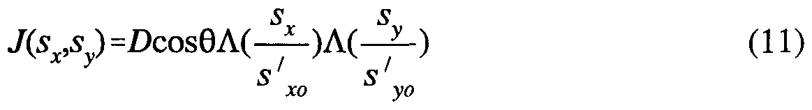
- the radiant intensity of the angular spectrum of the scattered beam, J(s), is obtained as a function of the observation unit vector, s, with respect to (S x , S y )-coordinates.
- the angular spectral distribution is computed as a function of recording geometry and incident beam.
- the recording aperture For the rectangular aperture of the original diffuser the recording aperture has the form:
- the recording geometry illustrated in FIG. 12 has coordinates (u,v).
- the recording monochromatic plane wave 300 has a wavelength of ⁇ R .
- the rectangular recording aperture 310 of the primary non-Lambertian diffuser 320 was applied at a physical distance, h, from the non-Lambertian diffuser recording plate 330 (x,y).
- the size of the aperture is represented by (L,W).
- FIGS. 14(a)- 14(g) One technique for plane surface diffuser replication is illustrated in FIGS. 14(a)- 14(g). Referring to FIGS. 14(a)-(g), a nickel electroforming technique for submicron surface relief replication is well suited to low cost replication.
- FIG. 14(a)-(g) a nickel electroforming technique for submicron surface relief replication is well suited to low cost replication.
- FIG. 14a illustrates a holographic master recording step where a master hologram includes a photopolymer layer 500 adjacent a substrate layer 510.
- a silver coating 530 has been applied to photopolymer 500.
- FIG. 14c a nickle "silver master” forming step is shown where the silver coated master holograpm has undergone electrolytic deposition of nickel silver master 540.
- FIG. 14d a nickel "silver master” separation step is shown where nickel silver master 540 is shown just after having been separated from the silver coated master holograpm.
- FIG. 14e a sub- master fabrication step of forming and separating is shown where a nickel submaster 550 is formed adjacent nickel silver master 540.
- FIG. 14e a sub- master fabrication step of forming and separating is shown where a nickel submaster 550 is formed adjacent nickel silver master 540.
- a shim (insert) fabrication step is shown where nickel submaster 550 has been separated and now provides the basis for replication of nickel shim 560.
- the step of replication is shown where nickel shim 560 provides the basis for replication of plastic layer 570.
- thermoforming a rod of cast, optical grade plastic (acrylic) is forced into a heated mold using a heated tool contoured to form a lens with the diffuser pattern.
- a concave mold that includes a submaster of a surface diffuser relief pattern can be used.
- a mold is used that includes a concave lens tool surface and an NIO tool surface.
- the mold is filled with optical grade plastic monomer and the monomer is polymerized to form the NIO portion simultaneously with the lens portion, the later of which includes the diffuser relief pattern.
- the polymerized work piece is then removed from the mold. Initiators are usually added to speed up this process and the mold is typically heated.
- molten plastic is forced into a mold that includes a lens tool surface and an NIO tool surface. Again, the lens tool surface includes the diffuser relief pattern. After the molten plastic cools, finished work piece is removed from the mold. In all cases, considerable care is required in controlling the temperature and the heating and cooling rates of the molds and the plastic. To maintain dimensional tolerances, the thermal expansion rates of the plastic and the mold must be considered.
- thermoforming or high pressure cold forming, can be used with a single mold to produce limited production quantities of the hybrid optical elements.
- a typical thermoforming method would include: providing an optical blank with said distal refractive end; providing a surface diffuser master; contacting said distal refractive end with said diffuser master; and then removing said diffuser master from said distal refractive end.
- Casting is the normal technique for producing simple shapes, particularly rods and tubes in optical grade acrylic.
- a typical casting process would include: providing a mold i) defining a void and ii) including a surface diffuser master; filling said mold with a molding material so as to fill said void and contact said surface diffuser master with said molding material; polymerizing said molding material; and removing said solid integrated beamformer from said mold.
- acrylic, or other plastic monomers requires the use of careful handling techniques to contain the vapor and avoid human exposure, possible fire risks, and environmental release.
- a typical injection molding process would include: providing a mold i) defining a void and ii) including a surface diffuser master; injecting a molding material into said mold so as to fill said void and contact said surface diffuser master with said molding material; allowing said molding material to cool and removing said solid integrated beamformer from said mold.
- Another method of manufacturing the solid integrated beamformer is laminating a surface diffuser to the distal refractive end.
- a typical laminating procedure would include: providing an optical blank with said distal refractive end; providing a surface diffuser layer; and attaching said surface diffuser layer to said distal refractive end.
- the particular manufacturing process is not essential to the present invention as long as it provides the described transformation. Normally the manufacturers of this product will select the manufacturing process as a matter of design choice based upon tooling and energy requirements, in view of the expected application requirements of the final product and the demands of the overall manufacturing process.
- the particular material used for the beam transformer should be suitable for the manufacturing process and the expected end-use conditions.
- the beamformer of the present invention can be made of any transparent thermoplastic material. It is preferred that the material be transparent in the visible spectrum. For the manufacturing operation, it is moreover an advantage to employ an acrylic or polycarbonate material.
- the particular material selected is not essential to the present invention, so long as it provides the described function. Normally, the manufacturers of this product will select the best commercially available material as a matter of design choice based upon the economics of cost and availability, in view of the expected application requirements of the final product and the demands of the overall manufacturing process.
- preferred embodiments of the present invention can be identified one at a time by testing for the presence of high definition.
- the test for the presence of high definition can be carried out without undue experimentation by the use of a simple and conventional light scattering assay experiment.
- Such scattering measurements can be performed using the automated scattering apparatus illustrated in FIG. 15.
- a surface diffuser 600 (with, or without, a fiber-NIO/RO combination) is mounted on a stand 610 and illuminated with a collimated beam 620 from HeNe laser 630.
- the distribution of the light scattered in the forward direction is measured using a silicon photodiode 640 mounted on a rotation arm 650.
- the entire system is fully automated and the light scattering data is automatically acquired, normalized, and plotted.
- Data obtained by swinging rotation arm 650 through arc 660 is acquired and analyzed by a data control and data acquisition system 670.
- the experiment can then be repeated using a fiber/NIO combination with white light illumination and the two scattering plots are compared.
- the contour of the parabolic section can be calculated.
- the contour is given in Table 2.
- remote source lighting include high efficiency, reduced power consumption, reduced life-cycle costs, increased ease of use and reduced maintenance and repair, much higher reliability and, optionally, redundancy.
- the benefits of remote source lighting are clearly of interest to those who light airports, ammunition storage areas, toxic sites, inaccessible areas, signal and warning lights. These advantages include permanent and water tight installation.
- the Defense Explosive Safety Board currently requires the use of vapor-tight explosion-proof light fixtures in all explosive environments. Whenever a bulb requires replacement, all flammable materials (stored or work-in-process) must be removed from the room and the fixture cleaned with steam to remove explosive particles before bulb replacement. The use of remote source lighting, with the illumination source outside the room, would cut the capital cost of such fixtures. Further, maintenance costs and down time for illumination source replacement would also be reduced.
- performance could be enhanced by providing more complicated NIO shapes.
- acrylic or polycarbonate is preferred for the solid integrated beamformer, any suitable material could be used in its place.
- the individual components need not be fabricated from the disclosed materials, but could be fabricated from virtually any suitable materials.
- the individual components need not be formed in the disclosed shapes, or assembled in the disclosed configuration, but could be provided in virtually any shape, and assembled in virtually any configuration, which function so as to provide a distal end for RSL.
- the solid integrated beamformer described herein is a physically separate module, it will be manifest that the solid integrated beamformer may be integrated into the apparatus with which it is associated.
- all the disclosed features of each disclosed embodiment can be combined with, or substituted for, the disclosed features of every other disclosed embodiment except where such features are mutually exclusive.
Landscapes
- Physics & Mathematics (AREA)
- General Physics & Mathematics (AREA)
- Optics & Photonics (AREA)
- Engineering & Computer Science (AREA)
- Manufacturing & Machinery (AREA)
- Microelectronics & Electronic Packaging (AREA)
- Diffracting Gratings Or Hologram Optical Elements (AREA)
Abstract
Description

Claims
Priority Applications (2)
| Application Number | Priority Date | Filing Date | Title |
|---|---|---|---|
| JP10519713A JP2001503158A (en) | 1996-10-21 | 1997-10-20 | Integrated beam former and manufacturing method thereof |
| EP97911943A EP0934488A4 (en) | 1996-10-21 | 1997-10-20 | Integrated beamformer and methods of manufacture thereof |
Applications Claiming Priority (2)
| Application Number | Priority Date | Filing Date | Title |
|---|---|---|---|
| US73394096A | 1996-10-21 | 1996-10-21 | |
| US08/733,940 | 1996-10-21 |
Publications (1)
| Publication Number | Publication Date |
|---|---|
| WO1998017943A1 true WO1998017943A1 (en) | 1998-04-30 |
Family
ID=24949707
Family Applications (1)
| Application Number | Title | Priority Date | Filing Date |
|---|---|---|---|
| PCT/US1997/019500 Ceased WO1998017943A1 (en) | 1996-10-21 | 1997-10-20 | Integrated beamformer and methods of manufacture thereof |
Country Status (3)
| Country | Link |
|---|---|
| EP (1) | EP0934488A4 (en) |
| JP (1) | JP2001503158A (en) |
| WO (1) | WO1998017943A1 (en) |
Cited By (6)
| Publication number | Priority date | Publication date | Assignee | Title |
|---|---|---|---|---|
| JP2002523863A (en) * | 1998-08-25 | 2002-07-30 | フィジィカル オプティクス コーポレーション | Apparatus with light source and sol-gel monolithic diffuser |
| FR2836237A1 (en) * | 2002-02-21 | 2003-08-22 | Framatome Connectors Int | Optical interconnection module, especially for optical fibers, has optical section overmolded in housing to form optical wave guide |
| WO2008034418A3 (en) * | 2006-09-19 | 2008-05-29 | Sunvention Internat Gmbh | Solar multistage concentrator, and greenhouse |
| EP1774371A4 (en) * | 2004-07-27 | 2011-05-11 | Dolby Lab Licensing Corp | DIFFUSER PRESERVING LUMINANCE AND REDUCING PARALLAX |
| WO2019183718A1 (en) | 2018-03-24 | 2019-10-03 | Suntracker Technologies Ltd. | Diffused fiber-optic horticultural lighting |
| CN114200731A (en) * | 2021-12-08 | 2022-03-18 | 哈尔滨工程大学 | A device and method for regulating the polarization and direction of Cherenkov radiation |
Families Citing this family (2)
| Publication number | Priority date | Publication date | Assignee | Title |
|---|---|---|---|---|
| US7345824B2 (en) * | 2002-03-26 | 2008-03-18 | Trivium Technologies, Inc. | Light collimating device |
| JP5739443B2 (en) * | 2009-11-11 | 2015-06-24 | アルコン リサーチ, リミテッド | Structured illumination probe and method |
Citations (7)
| Publication number | Priority date | Publication date | Assignee | Title |
|---|---|---|---|---|
| US247229A (en) | 1880-12-10 | 1881-09-20 | Apparatus for lighting dwellings or other structures | |
| US4309093A (en) | 1977-12-28 | 1982-01-05 | Canon Kabushiki Kaisha | Camera having a diffusing plate with rotationally asymmetric light diffusion property |
| US4336978A (en) | 1978-12-26 | 1982-06-29 | Canon Kabushiki Kaisha | Method for optically making a diffusion plate |
| US4898450A (en) | 1987-08-31 | 1990-02-06 | Physical Optics Corporation | Expanded beam non-imaging fiber optic connector |
| US5365354A (en) | 1990-10-02 | 1994-11-15 | Physical Optics Corporation | Grin type diffuser based on volume holographic material |
| US5534386A (en) | 1993-07-27 | 1996-07-09 | Physical Optics Corporation | Homogenizer formed using coherent light and a holographic diffuser |
| US5629996A (en) | 1995-11-29 | 1997-05-13 | Physical Optics Corporation | Universal remote lighting system with nonimaging total internal reflection beam transformer |
Family Cites Families (2)
| Publication number | Priority date | Publication date | Assignee | Title |
|---|---|---|---|---|
| DE2240780A1 (en) * | 1972-08-18 | 1974-02-28 | Standard Elektrik Lorenz Ag | LIGHT EMISSION CELL FOR OPTICAL FIBER LIGHT GUIDE |
| FR2704656B1 (en) * | 1993-04-29 | 1995-06-30 | Silec Liaisons Elec | Light scattering device associated with a light source comprising a series of point elements. |
-
1997
- 1997-10-20 WO PCT/US1997/019500 patent/WO1998017943A1/en not_active Ceased
- 1997-10-20 JP JP10519713A patent/JP2001503158A/en active Pending
- 1997-10-20 EP EP97911943A patent/EP0934488A4/en not_active Withdrawn
Patent Citations (7)
| Publication number | Priority date | Publication date | Assignee | Title |
|---|---|---|---|---|
| US247229A (en) | 1880-12-10 | 1881-09-20 | Apparatus for lighting dwellings or other structures | |
| US4309093A (en) | 1977-12-28 | 1982-01-05 | Canon Kabushiki Kaisha | Camera having a diffusing plate with rotationally asymmetric light diffusion property |
| US4336978A (en) | 1978-12-26 | 1982-06-29 | Canon Kabushiki Kaisha | Method for optically making a diffusion plate |
| US4898450A (en) | 1987-08-31 | 1990-02-06 | Physical Optics Corporation | Expanded beam non-imaging fiber optic connector |
| US5365354A (en) | 1990-10-02 | 1994-11-15 | Physical Optics Corporation | Grin type diffuser based on volume holographic material |
| US5534386A (en) | 1993-07-27 | 1996-07-09 | Physical Optics Corporation | Homogenizer formed using coherent light and a holographic diffuser |
| US5629996A (en) | 1995-11-29 | 1997-05-13 | Physical Optics Corporation | Universal remote lighting system with nonimaging total internal reflection beam transformer |
Non-Patent Citations (17)
Cited By (11)
| Publication number | Priority date | Publication date | Assignee | Title |
|---|---|---|---|---|
| JP2002523863A (en) * | 1998-08-25 | 2002-07-30 | フィジィカル オプティクス コーポレーション | Apparatus with light source and sol-gel monolithic diffuser |
| EP1112531A4 (en) * | 1998-08-25 | 2004-07-28 | Physical Optics Corp | Apparatus having a light source and sol-gel monolithic diffuser |
| FR2836237A1 (en) * | 2002-02-21 | 2003-08-22 | Framatome Connectors Int | Optical interconnection module, especially for optical fibers, has optical section overmolded in housing to form optical wave guide |
| WO2003071323A3 (en) * | 2002-02-21 | 2004-09-02 | Framatome Connectors Int | Optical interconnect module, and ferrule comprising same |
| EP1774371A4 (en) * | 2004-07-27 | 2011-05-11 | Dolby Lab Licensing Corp | DIFFUSER PRESERVING LUMINANCE AND REDUCING PARALLAX |
| US8294658B2 (en) | 2004-07-27 | 2012-10-23 | Dolby Laboratories Licensing Corporation | Parallax-reducing, luminance-preserving diffuser |
| WO2008034418A3 (en) * | 2006-09-19 | 2008-05-29 | Sunvention Internat Gmbh | Solar multistage concentrator, and greenhouse |
| WO2019183718A1 (en) | 2018-03-24 | 2019-10-03 | Suntracker Technologies Ltd. | Diffused fiber-optic horticultural lighting |
| EP3775671A4 (en) * | 2018-03-24 | 2022-01-26 | Suntracker Technologies Ltd. | HORTICULTURAL LIGHTING WITH DIFFUSED FIBER OPTIC |
| CN114200731A (en) * | 2021-12-08 | 2022-03-18 | 哈尔滨工程大学 | A device and method for regulating the polarization and direction of Cherenkov radiation |
| CN114200731B (en) * | 2021-12-08 | 2025-04-29 | 哈尔滨工程大学 | A device and method for controlling the polarization and direction of Cherenkov radiation |
Also Published As
| Publication number | Publication date |
|---|---|
| EP0934488A4 (en) | 1999-12-08 |
| EP0934488A1 (en) | 1999-08-11 |
| JP2001503158A (en) | 2001-03-06 |
Similar Documents
| Publication | Publication Date | Title |
|---|---|---|
| US5629996A (en) | Universal remote lighting system with nonimaging total internal reflection beam transformer | |
| US20240027675A1 (en) | Thin and flexible edge-lit waveguide illumination systems with complex surface topologies and light converting properties | |
| US6072551A (en) | Backlight apparatus for illuminating a display with controlled light output characteristics | |
| US6130730A (en) | Backlight assembly for a display | |
| US5857041A (en) | Optical coupler and method utilizing optimal illumination reflector | |
| US6639733B2 (en) | High efficiency non-imaging optics | |
| WO1997020169A9 (en) | Universal remote lighting system | |
| EP0235447B1 (en) | A totally internally reflecting light conduit | |
| US5842767A (en) | Highly efficient illuminator and method of use thereof | |
| WO2011143015A1 (en) | Optical beam shaping devices using microfacets | |
| WO1998017943A1 (en) | Integrated beamformer and methods of manufacture thereof | |
| US7548376B2 (en) | Total internal reflection micro lens array | |
| WO1997043673A1 (en) | Reflector and illumination system | |
| JP2002523799A (en) | Apparatus comprising an optical element having an integrally formed surface diffuser | |
| Shealy | Historical perspective of laser beam shaping | |
| Saxe et al. | Progress in the development of prism light guides | |
| RU2788422C1 (en) | Optical system for remote energy transmission based on powerful fiber lasers | |
| CN217441548U (en) | Optical device and lighting device | |
| RU2790198C1 (en) | Optical system for shaping and guidance of a laser radiation beam | |
| Tsai et al. | Quadratic Bézier curve method for continuous freeform optical surface design | |
| RU2715083C1 (en) | Laser beam formation and guidance optical system | |
| Jiménez-Rodríguez et al. | Some aspects for analytically designing flat aspheric converging Fresnel-type imaging mirror | |
| Savant et al. | Anamorphic lighting STAR display architecture for safe landing | |
| Shatz et al. | Optimal design of a bifurcated refractive coupler for the HEDlight program |
Legal Events
| Date | Code | Title | Description |
|---|---|---|---|
| AK | Designated states |
Kind code of ref document: A1 Designated state(s): JP |
|
| AL | Designated countries for regional patents |
Kind code of ref document: A1 Designated state(s): AT BE CH DE DK ES FI FR GB GR IE IT LU MC NL PT SE |
|
| DFPE | Request for preliminary examination filed prior to expiration of 19th month from priority date (pct application filed before 20040101) | ||
| 121 | Ep: the epo has been informed by wipo that ep was designated in this application | ||
| ENP | Entry into the national phase |
Ref country code: JP Ref document number: 1998 519713 Kind code of ref document: A Format of ref document f/p: F |
|
| WWE | Wipo information: entry into national phase |
Ref document number: 1997911943 Country of ref document: EP |
|
| WWP | Wipo information: published in national office |
Ref document number: 1997911943 Country of ref document: EP |
|
| WWW | Wipo information: withdrawn in national office |
Ref document number: 1997911943 Country of ref document: EP |