WO1997034908A1 - Process and device for isolating nucleic acids - Google Patents
Process and device for isolating nucleic acids Download PDFInfo
- Publication number
- WO1997034908A1 WO1997034908A1 PCT/DE1997/000517 DE9700517W WO9734908A1 WO 1997034908 A1 WO1997034908 A1 WO 1997034908A1 DE 9700517 W DE9700517 W DE 9700517W WO 9734908 A1 WO9734908 A1 WO 9734908A1
- Authority
- WO
- WIPO (PCT)
- Prior art keywords
- nucleic acids
- elution
- electrophoresis
- electrodes
- reaction space
- Prior art date
- Legal status (The legal status is an assumption and is not a legal conclusion. Google has not performed a legal analysis and makes no representation as to the accuracy of the status listed.)
- Ceased
Links
Classifications
-
- C—CHEMISTRY; METALLURGY
- C12—BIOCHEMISTRY; BEER; SPIRITS; WINE; VINEGAR; MICROBIOLOGY; ENZYMOLOGY; MUTATION OR GENETIC ENGINEERING
- C12Q—MEASURING OR TESTING PROCESSES INVOLVING ENZYMES, NUCLEIC ACIDS OR MICROORGANISMS; COMPOSITIONS OR TEST PAPERS THEREFOR; PROCESSES OF PREPARING SUCH COMPOSITIONS; CONDITION-RESPONSIVE CONTROL IN MICROBIOLOGICAL OR ENZYMOLOGICAL PROCESSES
- C12Q1/00—Measuring or testing processes involving enzymes, nucleic acids or microorganisms; Compositions therefor; Processes of preparing such compositions
- C12Q1/68—Measuring or testing processes involving enzymes, nucleic acids or microorganisms; Compositions therefor; Processes of preparing such compositions involving nucleic acids
- C12Q1/6806—Preparing nucleic acids for analysis, e.g. for polymerase chain reaction [PCR] assay
-
- C—CHEMISTRY; METALLURGY
- C12—BIOCHEMISTRY; BEER; SPIRITS; WINE; VINEGAR; MICROBIOLOGY; ENZYMOLOGY; MUTATION OR GENETIC ENGINEERING
- C12N—MICROORGANISMS OR ENZYMES; COMPOSITIONS THEREOF; PROPAGATING, PRESERVING, OR MAINTAINING MICROORGANISMS; MUTATION OR GENETIC ENGINEERING; CULTURE MEDIA
- C12N15/00—Mutation or genetic engineering; DNA or RNA concerning genetic engineering, vectors, e.g. plasmids, or their isolation, preparation or purification; Use of hosts therefor
- C12N15/09—Recombinant DNA-technology
- C12N15/10—Processes for the isolation, preparation or purification of DNA or RNA
- C12N15/1003—Extracting or separating nucleic acids from biological samples, e.g. pure separation or isolation methods; Conditions, buffers or apparatuses therefor
- C12N15/1017—Extracting or separating nucleic acids from biological samples, e.g. pure separation or isolation methods; Conditions, buffers or apparatuses therefor by filtration, e.g. using filters, frits, membranes
-
- G—PHYSICS
- G01—MEASURING; TESTING
- G01N—INVESTIGATING OR ANALYSING MATERIALS BY DETERMINING THEIR CHEMICAL OR PHYSICAL PROPERTIES
- G01N1/00—Sampling; Preparing specimens for investigation
- G01N1/28—Preparing specimens for investigation including physical details of (bio-)chemical methods covered elsewhere, e.g. G01N33/50, C12Q
- G01N1/40—Concentrating samples
-
- G—PHYSICS
- G01—MEASURING; TESTING
- G01N—INVESTIGATING OR ANALYSING MATERIALS BY DETERMINING THEIR CHEMICAL OR PHYSICAL PROPERTIES
- G01N27/00—Investigating or analysing materials by the use of electric, electrochemical, or magnetic means
- G01N27/26—Investigating or analysing materials by the use of electric, electrochemical, or magnetic means by investigating electrochemical variables; by using electrolysis or electrophoresis
- G01N27/416—Systems
- G01N27/447—Systems using electrophoresis
-
- G—PHYSICS
- G01—MEASURING; TESTING
- G01N—INVESTIGATING OR ANALYSING MATERIALS BY DETERMINING THEIR CHEMICAL OR PHYSICAL PROPERTIES
- G01N35/00—Automatic analysis not limited to methods or materials provided for in any single one of groups G01N1/00 - G01N33/00; Handling materials therefor
- G01N35/0098—Automatic analysis not limited to methods or materials provided for in any single one of groups G01N1/00 - G01N33/00; Handling materials therefor involving analyte bound to insoluble magnetic carrier, e.g. using magnetic separation
-
- G—PHYSICS
- G01—MEASURING; TESTING
- G01N—INVESTIGATING OR ANALYSING MATERIALS BY DETERMINING THEIR CHEMICAL OR PHYSICAL PROPERTIES
- G01N35/00—Automatic analysis not limited to methods or materials provided for in any single one of groups G01N1/00 - G01N33/00; Handling materials therefor
- G01N35/10—Devices for transferring samples or any liquids to, in, or from, the analysis apparatus, e.g. suction devices, injection devices
- G01N35/1081—Devices for transferring samples or any liquids to, in, or from, the analysis apparatus, e.g. suction devices, injection devices characterised by the means for relatively moving the transfer device and the containers in an horizontal plane
- G01N35/109—Devices for transferring samples or any liquids to, in, or from, the analysis apparatus, e.g. suction devices, injection devices characterised by the means for relatively moving the transfer device and the containers in an horizontal plane with two horizontal degrees of freedom
Definitions
- the invention relates to a method and a device for isolating nucleic acids.
- PCR polymerase chain reaction
- nucleic acids e.g. hybridization, purification and concentration of the nucleic acids to be analyzed play an important role.
- step a the liquid sample is passed through a glass fiber fleece on which the nucleic acids adsorb. Then the glass fiber fleece is included different solutions washed. Finally, the nucleic acids are eluted from the solid phase in the presence of low ionic strength buffers.
- the known method is disadvantageous in several respects: When the solid phase is washed, the sample can become contaminated. In addition, due to the capillary forces in the glass fiber fleece, the nucleic acids can only be partially recovered from it.
- nucleic acids are bound to gels and then brought back into solution by means of electroelution. This can also contaminate the solution.
- the nucleic acids are present in the solution in high dilution. There is no concentration.
- the object of the present invention is to provide a method and a device with which the disadvantages of the prior art are avoided.
- a method and a device for isolating nucleic acids are to be specified which enable simple and inexpensive purification and concentration of nucleic acids.
- the invention aims to avoid contamination.
- SPARE BLADE (RULE 26) According to the invention, a method for isolating nucleic acids from biological liquids and suspensions containing nucleic acids is provided, wherein
- nucleic acids are bound to an adsorbent
- the method enables a simple way to purify and concentrate nucleic acids from liquids.
- the risk of contamination can largely be ruled out, particularly in the case of an automatic process control.
- Elution can be done by changing the buffer or electrically by electroelution or electrophoresis.
- a device for isolating nucleic acids from biological liquids and suspensions containing nucleic acids is provided, a reaction space for receiving an adsorbent loaded with nucleic acids being connected to a removal space and the nucleic acids being movable from the reaction space into the removal space by means of an electrophoresis device and can be enriched there.
- This device enables a simple and inexpensive concentration and isolation of nucleic acids. By providing a special one Contamination can largely be excluded in the removal room.
- FIG. 1 is a schematic cross-sectional view of a first exemplary embodiment of the device
- FIG. 2 shows the embodiment of FIG. 1 with "spin column"
- FIG. 3 shows a schematic cross-sectional view of a second exemplary embodiment of the device
- FIG. 4 shows a schematic cross-sectional view through a first exemplary embodiment of a purification and enrichment device with a device according to FIG. 3,
- FIG. 5 is a plan view of an agarose flat bed gel
- 6a is a schematic cross-sectional view of a third embodiment of the device.
- FIG. 6b shows a modification of the embodiment shown in FIG. 6a
- 6c shows a schematic cross-sectional view of a fourth exemplary embodiment of the device
- FIG. 7a is a bottom view of a fifth embodiment of the device.
- ERSATZBL ⁇ TT (REGEL26) 7b is a plan view of the embodiment of FIG. 7a
- FIG. 7c is a schematic side view of the embodiment of FIG. 7a
- Fig. 7d is a perspective view of a cover for a first embodiment of a
- FIG. 7e is a perspective view of the first embodiment of the elution device without a lid
- FIGS. 7a to 7c are perspective views of the embodiment of FIGS. 7a to 7c.
- FIG. 8 is a schematic cross-sectional view through a sixth embodiment of the device.
- FIG. 10 shows a schematic cross-sectional view through a seventh exemplary embodiment of the device
- FIG. 11 is a schematic cross-sectional view through an eighth embodiment of the device.
- Fig. 12 is a plan view of a second embodiment of an elution device.
- FIG. 13 shows a schematic cross-sectional view through a second exemplary embodiment of a purification and enrichment device.
- REPLACEMENT BUTT (RULE 26) 1 shows a schematic cross section of a first exemplary embodiment of the device.
- a container 15 is accommodated in an electrophoresis buffer tank 10 with a bottom opening 43.
- the container 15 encloses a reaction space 17, which is connected to a removal space 50 via a channel 49.
- the volume of the reaction space 17 is preferably 1 to 20 ml.
- the removal space 50 is ionically connected to an electrophoresis buffer accommodated in the electrophoresis buffer tank 10 by means of a first permeable membrane 30 closing a first opening 42.
- the volume of the removal space 50 is preferably 0.005 to 0.1 ml.
- the first permeable membrane 30 is formed, for example, from a dialysis membrane which is not permeable to nucleic acids, but is permeable to salts, in particular chaotropic salts.
- the first permeable membrane 30 is by means of a flexible ring, e.g. a 0-ring, attached to a first nozzle 41.
- An adsorbent 100 e.g. a glass fiber fleece, silica, glass beads, glass-containing magnetic particles, anion exchangers or the like, added.
- a cathode 20a projects into the reaction space 17 through a second opening 80.
- An anode 20b dips into the electrophoresis buffer located in the electrophoresis buffer tank 10, the fill level of which is designated by 70.
- a second nozzle 85 extends from the container 15 and passes through the opening 43.
- the second nozzle 85 is sealed off from the electrophoresis buffer tank 10 by means of an O-ring 40.
- the removal space 50 has a removal opening 60. It is designed so that air pockets are avoided.
- the removal space 50 can in particular be designed as a capillary.
- FIG. 2 essentially shows the first exemplary embodiment shown in FIG. 1.
- a spin column "90 is included.
- a second nozzle 85 passing through the electrophoresis buffer tank 10 is not provided here.
- FIG. 3 shows a schematic cross-sectional view through a second exemplary embodiment of the device.
- the cathode 20a is located outside the reaction space 17. It is immersed directly in the electrophoresis buffer tank 10.
- a third nozzle 45 is provided, the third opening 46 of which is closed by a second permeable membrane 31.
- FIG. 4 shows a schematic cross-sectional view through a first exemplary embodiment of a purification and enrichment device with the device according to FIG. 3.
- the device according to FIG. 3 is in the effective range of an x, y, z pipettor whose x, y, z Pipetting arm is designated 190.
- the x, y, z pipette arm 190 receives a pipette tip 180, preferably a disposable tip.
- a suitable x, y, z pipettor is, for example. offered by TECAN AG, Switzerland.
- a heatable shaking block 170 is arranged in the effective area of the x, y, z pipettor.
- Reaction tubes 150 for lysis are accommodated in the debris block 170.
- a first vessel 160 for lysis a second vessel 162 for receiving a wash solution and sample vessels 165.
- a supply of pipette tips is designated by 185 and PCR vessels are designated by 210.
- the electrophoresis buffer tank 10 is provided with a full nozzle 125 which is connected to an electrophoresis buffer supply 110 with the interposition of a pump 120.
- the second connection piece 85 and a discharge line 140 provided at the bottom of the electrophoresis buffer tank 10 are connected to a second pump 130 m.
- the second pump 130 is preferably designed as a hose pump.
- a suitable hose pump is e.g. offered by Cavro, California, USA.
- the cathode 20a and the anode 20b are connected to a voltage source 220 via electrical leads 225a and 225b.
- the first 120 and the second pump 130, the shaking device 170, the x, y, z pipettor and the voltage source 220 are designed so that they can be controlled by means of a process computer. A fully automatic operation of the purification and enrichment device is thus possible.
- FIG. 5 shows a top view of a particularly simple variant of a container 15. This is made from an agarose flat bed gel 11, on the opposite transverse sides of which the cathode 20a and the anode 20b rest.
- a first recess 81 forming the reaction space 17 for receiving adsorbent
- a second recess 61 forming the reaction space 17 for receiving adsorbent
- the second recess 61 is slit-shaped. It serves to remove the nucleic acids enriched therein.
- FIG. 6a shows a schematic cross-sectional view through a third exemplary embodiment of the device.
- the container 15 is designed in the form of a cross connector.
- the adsorbent 100 is located on a support fleece 302.
- the cathode 20a and the anode 20b are formed as electrically conductive plastic pipette tips, which are connected to the electrophoresis buffer tank (not shown here). They are connected to the container 15 via hose pieces 318. Nucleic acids enriched in the removal space 50 can be withdrawn through the removal opening 60.
- the container 15 consists of a cuboid part.
- the reaction space 17 is formed by a hole.
- Recesses 320, 321 for receiving the cathode 20a and the anode 20b are provided on both sides next to the reaction space 17.
- the wall between the recesses 320, 321 and the reaction space 17 is ion-conductive.
- the recesses 320 serve to receive electrophoresis buffers. They are closed with a plug 340.
- the electrophoresis buffer tank consists of two partial containers which surround the reaction space 17. A plurality of such devices, of which another is shown in perspective in FIG.
- the elution device can be components of the first exemplary embodiment of an elution device shown in FIGS. 7d and 7e.
- the elution device essentially consists of a multiple container 410 for holding several devices according to FIG. 7f.
- the multiple container 410 has a vacuum connection 401 and connections 402 for a liquid circuit for heating the elution device.
- the lid 400 shown in FIG. 7d is provided with leads 226a, 226b for the electrodes.
- the cathode 20a is integrated in the wall of the reaction space 17 and the anode 20b m the opposite wall of the removal space 50.
- Eme permeable, in particular a semipermeable, membrane 310 is provided in the removal space 50, which membrane is impermeable to nucleic acids. The membrane 310 prevents the nucleic acids from reaching the anode 20b and
- SPARE BLADE (RULE 26) be destroyed there by redox processes.
- the adsorbent 100 is supported by a support fleece 302 at the entrance of the second nozzle 85.
- a first layer 323 applied to the noble metal or plastic consists of biotinylated bovine serum albumin, a second layer 325 resting thereon consists of a streptavidin or polystreptavidin and an outer third layer 324 is formed from an oligonucleotide.
- a movable permanent magnet 312 is arranged on the outside of the container 15 in such a way that its north pole is in the vicinity of the cathode 20a.
- the reaction space 17 is closed with a transparent snap cover 316.
- the removal space 50 is closed with a snap cover 326, which is provided with a septum 328.
- the septum 328 can be pierced by means of a needle 327 to remove or add liquid. Contamination of the liquid in the device can thus be avoided.
- 314 denotes a photomultiplier, which is arranged above the transparent snap cover 316.
- FIG. 11 shows a schematic cross section of an eighth exemplary embodiment.
- the movable permanent magnet 312 with its south pole is arranged near the outside of the anode 20b.
- the bottom of the removal space 50 is transparent. Is located opposite the removal opening 60
- FIG. 12 shows a plan view of a second exemplary embodiment of an elution device.
- a plurality of the devices shown in FIG. 11 are arranged side by side.
- Thermostatic plates 329 are provided on each of the long sides of the devices, with which the temperature can be adjusted.
- FIG. 13 shows a schematic cross-sectional view of a second exemplary embodiment of a purification and enrichment device.
- the electrodes 20a and 20b of a device according to FIG. 11 are connected to a voltage source 220.
- the device according to FIG. 11 is located in the effective range of an x, y, z pipetting arm 190 of an x, y, z pipetting robot.
- the voltage source 220, the second pump 130 for the disposal of solutions to be discarded, an apparatus (not shown here) for moving a permanent magnet 312 and the x, y, z pipetting robot can be controlled by means of a process computer, e.g. a personal computer, fully automatically controllable.
- Biological liquids containing nucleic acid to be analyzed are brought into contact with an adsorbent 100 m.
- the nucleic acids present in the solution adsorb onto the adsorbent 100.
- the adsorbent 100 loaded with the nucleic acids, for example. em Spm-column 90, the reaction space 17 is inserted through the second opening 80 m.
- REPLACEMENT SHEET (RULE 26) Charged nucleic acids are thereby released from the adsorbent 100 and moved in the direction of the anode 20b arranged in the vicinity of the removal space 50.
- a first permeable membrane 30 which is impermeable to nucleic acids is provided.
- the current passed through the electrophoresis buffer is turned off.
- An elution volume containing enriched nucleic acids can now be removed through the removal opening 60 of the removal space 50.
- the removal opening 60 can be closed with the snap lid 326, which is provided with a septum 328.
- the septum 328 can be pierced with a needle 327 to remove elution volume.
- electrodes 20a, 20b of different designs can be used.
- the device according to the invention can be combined with a device for the detection of chemiluminescence.
- a photomultiplier 314 is arranged in the vicinity of the container 15.
- the nucleic acids are moved electrophoretically by the adsorbent 100 m in the direction of the anode 20b.
- an amplification of the nucleic acids can be carried out.
- the amplified nucleic acids are then bound by adding magnetic particles.
- the permanent magnet 312 By moving the permanent magnet 312 to the anode 20b, the nucleic acids are loaded
- ERS ⁇ ZBL ⁇ TT (REGEL26) Magnetic particles attracted to the anode 20b. After adding a chemiluminescent buffer and applying a voltage across the electrodes 20a, 20b, a chemiluminescent is triggered. The light emitted in the process is detected by the photomultiplier 314.
- the above-mentioned functions can be automated by means of an x, y, z pipetting robot. It is thus possible to automatically operate a plurality of the devices according to the invention one after the other.
- the first recess 81 serves to receive the glass fleece and the second recess 61 is filled with electrophoresis buffer. In this way, the nucleic acid can be eluted electrophoretically from the glass fleece and transferred into the subsequent agarose gel and into the second recess 61.
- the isolated concentrated nucleic acid was removed from the second recess 61.
- SPARE BLADE (RULE 26) 20a, 20b, wires with a diameter of 0.3 mm of a platinum-ruthenium alloy were used and as a voltage generator of the electrophoresis voltage generator from Hölzel, Dorfen. 30 ⁇ l of elution volume with the nucleic acid were removed from the removal opening 60.
- EDTA whole blood was collected from the carotid artery from a freshly slaughtered white broiler and immediately mixed with ethylenediaminetetraacetic acid (Sigma, Kunststoff, Order No. E-5513) in a concentration of 0.06 g EDTA / ml whole blood.
- the EDTA whole blood was frozen in portions and stored at -15 ° C. All reagents are taken from the "High Pure PCR Template Preparation Kit" from Boehringer Mannheim (order no. 1 796 828). 100 ul EDTA whole blood (see above) were mixed with 200 ul lysis buffer and 60 ul proteinase K from the above Reagent set mixed and 15 min. incubated at 70 ° C.
- SPARE BLADE by applying a DC voltage of max. 10 mA at approx. 60 degrees. C performed.
- Biotinylated bovine immunoglobulin G (R-IgG) is first produced. 0.5 ml of an R-IgG solution (2 mg R-IgG
- the disks are then washed 3 times with 100 ml of Milli-Q water, the solid and liquid phases being separated by sedimentation or centrifugation.
- the slices are then taken up again in 40 ml of PBS.
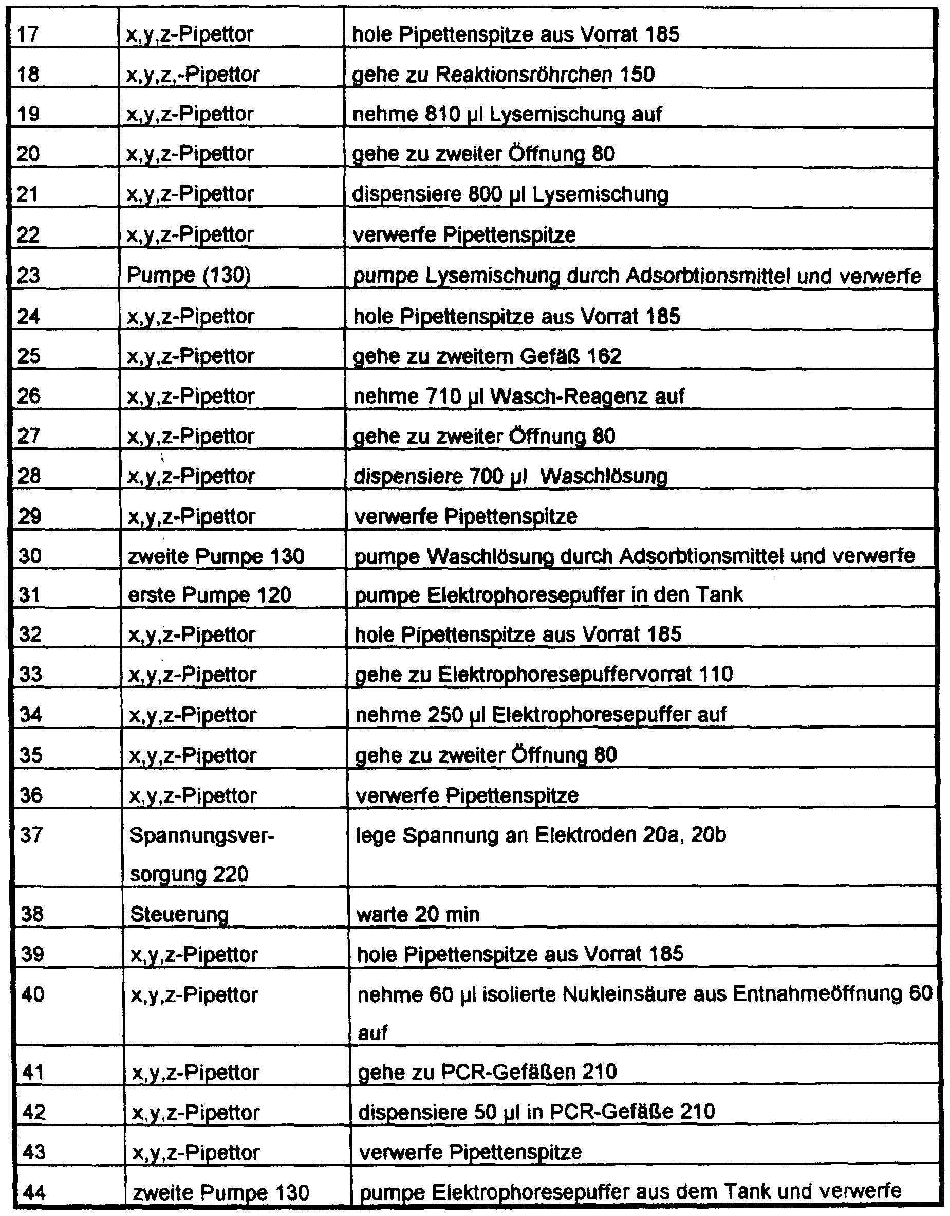
- the device shown in FIG. 14 was automatically controlled with a computer program with the following program steps for carrying out the isolation, amplification and chemiluminescence measurement:
Landscapes
- Chemical & Material Sciences (AREA)
- Health & Medical Sciences (AREA)
- Life Sciences & Earth Sciences (AREA)
- Engineering & Computer Science (AREA)
- Analytical Chemistry (AREA)
- General Health & Medical Sciences (AREA)
- Biochemistry (AREA)
- Immunology (AREA)
- Organic Chemistry (AREA)
- Physics & Mathematics (AREA)
- Genetics & Genomics (AREA)
- Zoology (AREA)
- Molecular Biology (AREA)
- Wood Science & Technology (AREA)
- Biotechnology (AREA)
- Pathology (AREA)
- Biomedical Technology (AREA)
- General Physics & Mathematics (AREA)
- General Engineering & Computer Science (AREA)
- Bioinformatics & Cheminformatics (AREA)
- Chemical Kinetics & Catalysis (AREA)
- Proteomics, Peptides & Aminoacids (AREA)
- Microbiology (AREA)
- Biophysics (AREA)
- Electrochemistry (AREA)
- Crystallography & Structural Chemistry (AREA)
- Plant Pathology (AREA)
- Apparatus Associated With Microorganisms And Enzymes (AREA)
- Saccharide Compounds (AREA)
- Investigating Or Analysing Biological Materials (AREA)
- Measuring Or Testing Involving Enzymes Or Micro-Organisms (AREA)
- Preparation Of Compounds By Using Micro-Organisms (AREA)
Abstract
Description
Verfahren und Vorrichtung zur Isolierung von Nukleinsäuren V experienced and device for isolation of nucleic acids
Die Erfindung betrifft ein Verfahren und eine Vorrichtung zur Isolierung von Nukleinsäuren.The invention relates to a method and a device for isolating nucleic acids.
Vor der Analyse von aus Zellen gewonnenen Nukleinsäuren mittels Polymerasekettenreaktion (PCR) ist es erforderlich, die Nukleinsäuren aufzureinigen und aufzukonzentrieren. Ferner kann es notwendig sein, aus der zu analysierenden Probe bestimmte die Polymerasekettenraktion störende Substanzen, wie die prosthetische Gruppe von Hämoglobin, von der Probe abzutrennen.Before analyzing nucleic acids obtained from cells using the polymerase chain reaction (PCR), it is necessary to purify and concentrate the nucleic acids. Furthermore, it may be necessary to separate certain substances, such as the prosthetic group of hemoglobin, which disrupt the polymerase chain fraction from the sample to be analyzed from the sample.
Daneben spielt auch bei anderen Techniken zur Analyse von Nukleinsäuren, bsp. der Hybridisierung, eine Aufreinigung und Aufkonzentration der zu analysierenden Nukleinsäuren eine wichtige Rolle.In addition, other techniques for analyzing nucleic acids, e.g. hybridization, purification and concentration of the nucleic acids to be analyzed play an important role.
Aus "Methods of Enzymology", Vol. 68, S. 170 - 182, ist es bekannt, zur Isolierung von Nukleinsäuren sog. "Spin-columns" zu verwenden. Dabei werden in einer aus der DE 41 39 664 AI bekannten Variante folgende Arbeitsschritte verwendet:From "Methods of Enzymology", Vol. 68, pp. 170-182, it is known to use so-called "spin columns" for the isolation of nucleic acids. The following steps are used in a variant known from DE 41 39 664 AI:
aa) Zellaufschluß, bb) Adsorption der Nukleinsäuren an einem Glasfaservlies inaa) cell disruption, bb ) adsorption of the nucleic acids on a glass fiber fleece in
Gegenwart eines Puffers mit hoher Ionenstärke und cc ) Elution der Nukleinsäuren mit einem Puffer geringer Ionenstärke.Presence of a buffer with high ionic strength and cc ) elution of the nucleic acids with a buffer with low ionic strength.
Beim Schritt lit.aa) wird die flüssige Probe durch ein Glasfaservlies geleitet, an dem die Nukleinsäuren adsorbieren. Anschließend wird das Glasfaservlies mit verschiedenen Losungen gewaschen. Schließlich werden die Nukleinsäuren in Anwesenheit von Puffern geringer Ionenstarke von der Festphase eluiert.In step a), the liquid sample is passed through a glass fiber fleece on which the nucleic acids adsorb. Then the glass fiber fleece is included different solutions washed. Finally, the nucleic acids are eluted from the solid phase in the presence of low ionic strength buffers.
Das bekannte Verfahren ist in mehrfacher Hinsicht nachteilig: Beim Waschen der Festphase kann es zur Kontamination der Probe kommen. Außerdem können wegen der im Glasfaservlies herrschenden Kapillarkräfte die Nukleinsäuren nur zum Teil daraus zurückgewonnen werden.The known method is disadvantageous in several respects: When the solid phase is washed, the sample can become contaminated. In addition, due to the capillary forces in the glass fiber fleece, the nucleic acids can only be partially recovered from it.
Des weiteren sind aus "Methods in Enzymology 65" (1980), S. 371 - 380 gelelektrophoretische Methoden bekannt, bei denen Nukleinsäuren an Gele gebunden und danach mittels Elektroelution wieder in Lösung gebracht werden. Auch dabei kann es zu Kontamination der Lösung kommen. Die Nukleinsäuren liegen in der Lösung in hoher Verdünnung vor. Eine Aufkonzentration findet nicht statt.Furthermore, from "Methods in Enzymology 65" (1980), pp. 371-380, gel electrophoretic methods are known in which nucleic acids are bound to gels and then brought back into solution by means of electroelution. This can also contaminate the solution. The nucleic acids are present in the solution in high dilution. There is no concentration.
Aufgabe der vorliegenden Erfindung ist es, ein Verfahren und eine Vorrichtung anzugeben, mit denen die Nachteile des Stands der Technik vermieden werden. Insbesondere soll ein Verfahren und eine Vorrichtung zur Isolierung von Nukleinsäuren angegeben werden, die eine einfache und kostengünstige Aufreinigung und Aufkonzentration von Nukleinsäuren ermöglichen. Außerdem soll eine weitgehend automatisierte Isolation und Aufkonzentration von Nukleinsäuren durchfuhrbar sein. Schließlich bezweckt die Erfindung die Vermeidung von Kontaminationen.The object of the present invention is to provide a method and a device with which the disadvantages of the prior art are avoided. In particular, a method and a device for isolating nucleic acids are to be specified which enable simple and inexpensive purification and concentration of nucleic acids. In addition, it should be possible to carry out a largely automated isolation and concentration of nucleic acids. Finally, the invention aims to avoid contamination.
Diese Aufgabe wird durch die Merkmale der Ansprüche 1 und 12 gelost. Zweckmäßige Ausgestaltungen des Verfahrens bzw. der Vorrichtung ergeben sich aus den Merkmalen der Ansprüche 2 bis 11 sowie 13 bis 41.This object is achieved by the features of claims 1 and 12. Expedient refinements of the method and the device result from the features of claims 2 to 11 and 13 to 41.
ERSATZBLÄTT(REGEL26) Nach Maßgabe der Erfindung ist ein Verfahren zur Isolierung von Nukleinsäuren aus biologischen nukleinsäurehaltigen Flüssigkeiten und Suspensionen vorgesehen, wobeiSPARE BLADE (RULE 26) According to the invention, a method for isolating nucleic acids from biological liquids and suspensions containing nucleic acids is provided, wherein
a) die Nukleinsäuren an ein Adsorptionsmittel gebunden werden,a) the nucleic acids are bound to an adsorbent,
b) die Nukleinsäuren vom Adsorptionsmittel eluiert undb) the nucleic acids eluted from the adsorbent and
c) durch Elektrophorese von einem Reaktionsraum in einen damit verbundenen Entnahmeraum bewegt und dort angereichert werden.c) moved by electrophoresis from a reaction space into an associated removal space and enriched there.
Das Verfahren ermöglicht auf einfachem Weg eine Aufreinigung und Aufkonzentration von Nukleinsäuren aus Flüssigkeiten. Insbesondere bei einer automatischen Verfahrensführung kann das Risiko einer Kontamination weitgehend ausgeschlossen werden. Die Elution kann durch Pufferwechsel oder elektrisch durch Elektroelution bzw. Elektrophorese erfolgen.The method enables a simple way to purify and concentrate nucleic acids from liquids. The risk of contamination can largely be ruled out, particularly in the case of an automatic process control. Elution can be done by changing the buffer or electrically by electroelution or electrophoresis.
Nach weiterer Maßgabe der Erfindung ist eine Vorrichtung zur Isolierung von Nukleinsäuren aus biologischen nukleinsäurehaltigen Flüssigkeiten und Suspensionen vorgesehen, wobei ein Reaktionsraum zur Aufnahme eines mit Nukleinsäuren beladenen Adsorptionsmittels mit einem Entnahmeraum verbunden ist, und wobei die Nukleinsäuren mittels einer Elektrophoreseeinrichtung vom Reaktions- in den Entnahmeraum bewegbar und dort anreicherbar sind. - Diese Vorrichtung ermöglicht eine einfach und kostengünstig durchführbare Aufkonzentration und Isolierung von Nukleinsäuren. Durch das Vorsehen eines besonderen Entnahmeraums kann eine Kontamination weitgehend ausgeschlossen werden.According to a further provision of the invention, a device for isolating nucleic acids from biological liquids and suspensions containing nucleic acids is provided, a reaction space for receiving an adsorbent loaded with nucleic acids being connected to a removal space and the nucleic acids being movable from the reaction space into the removal space by means of an electrophoresis device and can be enriched there. - This device enables a simple and inexpensive concentration and isolation of nucleic acids. By providing a special one Contamination can largely be excluded in the removal room.
Nachfolgend werden Ausfuhrungsbeispiele der Erfindung anhand der Zeichnung naher erläutert. Hier zeigen:Exemplary embodiments of the invention are explained in more detail below with reference to the drawing. Show here:
Fig. 1 eine schematische Querschnittsansicht eines ersten Ausfuhrungsbeispiels der Vorrichtung,1 is a schematic cross-sectional view of a first exemplary embodiment of the device,
Fig. 2 das Ausführungsbeispiel gemäß Fig. 1 mit "Spin- Column",2 shows the embodiment of FIG. 1 with "spin column",
Fig. 3 eine schematische Querschnittsansicht eines zweiten Ausführungsbeispiels der Vorrichtung,3 shows a schematic cross-sectional view of a second exemplary embodiment of the device,
Fig. 4 eine schematische Querschnittsansicht durch ein erstes Ausfuhrungsbeispiel einer Aufremigungs- und Anreicherungsvorrichtung mit einer Vorrichtung gemäß Fig. 3,4 shows a schematic cross-sectional view through a first exemplary embodiment of a purification and enrichment device with a device according to FIG. 3,
Fig. 5 eine Draufsicht auf ein Agaroseflachbettgel,5 is a plan view of an agarose flat bed gel,
Fig. 6a eine schematische Querschnittsansicht eines dritten Ausführungsbeispiels der Vorrichtung,6a is a schematic cross-sectional view of a third embodiment of the device,
Fig. 6b eine Abwandlung des in Fig. 6a gezeigten Ausführungsbeispiels,6b shows a modification of the embodiment shown in FIG. 6a,
Fig. 6c eine schematische Querschnittsansicht eines vierten Ausfuhrungsbeispiels der Vorrichtung,6c shows a schematic cross-sectional view of a fourth exemplary embodiment of the device,
Fig. 7a eine Untersicht eines fünften Ausführungsbeispiels der Vorrichtung,7a is a bottom view of a fifth embodiment of the device,
ERSATZBLÄTT(REGEL26) Fig. 7b eine Draufsicht auf das Ausführungsbeispiel gemäß Fig. 7a,ERSATZBL Ä TT (REGEL26) 7b is a plan view of the embodiment of FIG. 7a,
Fig. 7c eine schematische Seitenansicht des Ausführungsbeispiels gemäß Fig. 7a,7c is a schematic side view of the embodiment of FIG. 7a,
Fig. 7d eine perspektivische Ansicht eines Deckels für ein erstes Ausführungsbeispiel einerFig. 7d is a perspective view of a cover for a first embodiment of a
Elutionsvorrichtung,Elution device,
Fig. 7e eine perspektivische Ansicht des ersten Ausführungsbeispiels der Elutionsvorrichtung ohne Deckel,7e is a perspective view of the first embodiment of the elution device without a lid,
Fig. 7f eine perspektivische Ansicht des Ausführungsbeispiels gemäß Fig. 7a bis 7c,7f is a perspective view of the embodiment of FIGS. 7a to 7c,
Fig. 8 eine schematische Querschnittsansicht durch ein sechstes Ausführungsbeispiel der Vorrichtung,8 is a schematic cross-sectional view through a sixth embodiment of the device,
Fig. 9 eine schematische Querschnittsansicht durch eine beschichtete Elektrode,9 is a schematic cross-sectional view through a coated electrode,
Fig. 10 eine schematische Querschnittsansicht durch ein siebtes Ausführungsbeispiel der Vorrichtung,10 shows a schematic cross-sectional view through a seventh exemplary embodiment of the device,
Fig. 11 eine schematische Querschnittsansicht durch ein achtes Ausführungsbeispiel der Vorrichtung,11 is a schematic cross-sectional view through an eighth embodiment of the device,
Fig. 12 eine Draufsicht auf ein zweites Ausführungsbeispiel einer Elutionsvorrichtung undFig. 12 is a plan view of a second embodiment of an elution device and
Fig. 13 eine schematische Querschnittsansicht durch ein zweites Ausführungsbeispiel einer Aufreinigungs- und Anreicherungsvorrichtung.13 shows a schematic cross-sectional view through a second exemplary embodiment of a purification and enrichment device.
ERSATZBUTT(REGEL26) In Fig. 1 ist ein schematischer Querschnitt eines ersten Ausführungsbeispiels der Vorrichtung gezeigt. In einem Elektrophoresepuffertank 10 mit einem bodenseitigen Durchbruch 43 ist ein Behälter 15 aufgenommen. Der Behälter 15 umschließt einen Reaktionsraum 17, welcher über einen Kanal 49 mit einem Entnahmeraum 50 verbunden ist. Das Volumen des Reaktionsraums 17 beträgt vorzugsweise 1 bis 20 ml. Der Entnahmeraum 50 ist mittels einer eine erste Öffnung 42 verschließenden ersten permeablen Membran 30 ionenleitend mit einem im Elektrophoresepuffertank 10 aufgenommenen Elektrophoresepuffer verbunden. Das Volumen des Entnahmeraums 50 beträgt vorzugsweise 0,005 bis 0,1 ml. Die erste permeable Membran 30 ist z.B. aus einer Dialysemembran gebildet, welche für Nukleinsäuren nicht durchlässig, für Salze, insbesondere chaotrope Salze, jedoch durchlässig ist. Die erste permeable Membran 30 ist mittels eines flexiblen Rings, bsp. eines 0- Rings, auf einem ersten Stutzen 41 befestigt. Im Reaktionsraum 17 ist ein Adsorptionsmittel 100, bsp. ein Glasfaservlies, Silika, Glasperlen, mit Glas umfangene magnetische Partikel, Anionenaustauscher o. dgl., aufgenommen. In den Reaktionsraum 17 ragt durch eine zweite Öffnung 80 eine Kathode 20a. Eine Anode 20b taucht in den im Elektrophoresepuffertank 10 befindlichen Elektrophoresepuffer ein, dessen Füllstand mit 70 bezeichnet ist. Unterhalb des Adsorptionsmittels 100 erstreckt sich vom Behälter 15 ein zweiter Stutzen 85, der den Durchbruch 43 durchgreift. Der zweite Stutzen 85 ist mittels eines O-Rings 40 gegenüber dem Elektrophoresepuffertank 10 abgedichtet. - Der Entnahmeraum 50 weist eine Entnahmeöffnung 60 auf. Er ist so ausgebildet, daß Lufteinschlüsse vermieden werden. Der Entnahmeraum 50 kann insbesondere als Kapillare ausgebildet sein.REPLACEMENT BUTT (RULE 26) 1 shows a schematic cross section of a first exemplary embodiment of the device. A container 15 is accommodated in an electrophoresis buffer tank 10 with a bottom opening 43. The container 15 encloses a reaction space 17, which is connected to a removal space 50 via a channel 49. The volume of the reaction space 17 is preferably 1 to 20 ml. The removal space 50 is ionically connected to an electrophoresis buffer accommodated in the electrophoresis buffer tank 10 by means of a first permeable membrane 30 closing a first opening 42. The volume of the removal space 50 is preferably 0.005 to 0.1 ml. The first permeable membrane 30 is formed, for example, from a dialysis membrane which is not permeable to nucleic acids, but is permeable to salts, in particular chaotropic salts. The first permeable membrane 30 is by means of a flexible ring, e.g. a 0-ring, attached to a first nozzle 41. An adsorbent 100, e.g. a glass fiber fleece, silica, glass beads, glass-containing magnetic particles, anion exchangers or the like, added. A cathode 20a projects into the reaction space 17 through a second opening 80. An anode 20b dips into the electrophoresis buffer located in the electrophoresis buffer tank 10, the fill level of which is designated by 70. Below the adsorbent 100, a second nozzle 85 extends from the container 15 and passes through the opening 43. The second nozzle 85 is sealed off from the electrophoresis buffer tank 10 by means of an O-ring 40. - The removal space 50 has a removal opening 60. It is designed so that air pockets are avoided. The removal space 50 can in particular be designed as a capillary.
Fig. 2 zeigt im wesentlichen das in Fig. 1 gezeigte erste Ausführungsbeispiel. Dabei ist im Reaktionsraum 17 ein "Spin- column" 90 aufgenommen. Ein den Elektrophoresepuffertank 10 durchgreifender zweiter Stutzen 85 ist hier nicht vorgesehen.FIG. 2 essentially shows the first exemplary embodiment shown in FIG. 1. In this case, a "spin column "90 is included. A second nozzle 85 passing through the electrophoresis buffer tank 10 is not provided here.
In Fig. 3 ist eine schematische Querschnittsansicht durch em zweites Ausfuhrungsbeispiel der Vorrichtung gezeigt. Dabei befindet sich die Kathode 20a außerhalb des Reaktionsraums 17. Sie taucht direkt in den Elektrophoresepuffertank 10 ein. Am den Reaktionsraum 17 umgreifenden Teil des Behalters 15 ist em dritter Stutzen 45 vorgesehen, dessen dritte Öffnung 46 durch eine zweite permeable Membran 31 verschlossen ist.FIG. 3 shows a schematic cross-sectional view through a second exemplary embodiment of the device. The cathode 20a is located outside the reaction space 17. It is immersed directly in the electrophoresis buffer tank 10. On the part of the container 15 encompassing the reaction space 17, a third nozzle 45 is provided, the third opening 46 of which is closed by a second permeable membrane 31.
Fig. 4 zeigt eine schematische Querschnittsansicht durch ein erstes Ausfuhrungsbeispiel einer Aufreinigungs- und Anreicherungsvorrichtung mit der Vorrichtung gemäß Fig. 3. Die Vorrichtung gemäß Fig. 3 befindet sich im Wirkbereich eines x, y,z-Pipettors, dessen x,y, z-Pipettierarm mit 190 bezeichnet ist. Der x,y, z-Pipettierarm 190 nimmt eine Pipettierspitze 180, vorzugsweise eme Wegwerfspitze, auf. Em geeigneter x,y, z-Pipettor wird bsp. von der Firma TECAN AG, Schweiz, angeboten. Ferner ist im Wirkbereich des x,y,z- Pipettors ein heizbarer Schuttelbock 170 angeordnet. Im Schuttelbock 170 sind Reaktionsrohrchen 150 für die Lyse aufgenommen. Daneben befinden sich em erstes Gefäß 160 für die Lyse, ein zweites Gefäß 162 zur Aufnahme für eme Waschlosung sowie Probengefaße 165. Mit 185 ist ein Vorrat an Pipettenspitzen und mit 210 sind PCR-Gefaße bezeichnet.FIG. 4 shows a schematic cross-sectional view through a first exemplary embodiment of a purification and enrichment device with the device according to FIG. 3. The device according to FIG. 3 is in the effective range of an x, y, z pipettor whose x, y, z Pipetting arm is designated 190. The x, y, z pipette arm 190 receives a pipette tip 180, preferably a disposable tip. A suitable x, y, z pipettor is, for example. offered by TECAN AG, Switzerland. Furthermore, a heatable shaking block 170 is arranged in the effective area of the x, y, z pipettor. Reaction tubes 150 for lysis are accommodated in the debris block 170. Next to it are a first vessel 160 for lysis, a second vessel 162 for receiving a wash solution and sample vessels 165. A supply of pipette tips is designated by 185 and PCR vessels are designated by 210.
Der Elektrophoresepuffertank 10 ist mit einem Fullstutzen 125 versehen, der mit einem Elektrophoresepuffervorrat 110 unter Zwischenschaltung einer Pumpe 120 verbunden ist. Der zweite Stutzen 85 sowie eme am Boden des Elektrophoresepuffertanks 10 vorgesehene Ableitung 140 stehen mit einer zweiten Pumpe 130 m Verbindung. Die zweite Pumpe 130 ist vorzugsweise als Schlauchpumpe ausgeführt. Eme geeignete Schlauchpumpe wird bsp. von der Firma Cavro, Kalifornien, USA, angeboten. DieThe electrophoresis buffer tank 10 is provided with a full nozzle 125 which is connected to an electrophoresis buffer supply 110 with the interposition of a pump 120. The second connection piece 85 and a discharge line 140 provided at the bottom of the electrophoresis buffer tank 10 are connected to a second pump 130 m. The second pump 130 is preferably designed as a hose pump. A suitable hose pump is e.g. offered by Cavro, California, USA. The
ERSATZBLÄTT(REGEL26) Kathode 20a sowie die Anode 20b sind über elektrische Zuleitungen 225a bzw. 225b mit einer Spannungsquelle 220 verbunden. Die erste 120 und die zweite Pumpe 130, der Schuttelbock 170, der x,y, z-Pipettor sowie die Spannungsquelle 220 smd so ausgeführt, daß sie mittels eines Prozeßrechners ansteuerbar smd. Somit ist em vollautomatischer Betrieb der Aufreinigungs- und Anreicherungsvorrichtung möglich.SPARE BLADE (RULE 26) The cathode 20a and the anode 20b are connected to a voltage source 220 via electrical leads 225a and 225b. The first 120 and the second pump 130, the shaking device 170, the x, y, z pipettor and the voltage source 220 are designed so that they can be controlled by means of a process computer. A fully automatic operation of the purification and enrichment device is thus possible.
In Fig. 5 ist eme Draufsicht auf eine besonders einfache Variante eines Behalters 15 gezeigt. Dieser ist aus einem Agaroseflachbettgel 11 hergestellt, an dessen gegenüberliegenden Querseiten die Kathode 20a und die Anode 20b anliegen. Im Agaroseflachbettgel 11 ist eine erste den Reaktionsraum 17 bildende Ausnehmung 81 zur Aufnahme von Adsoptionsmittel und eine zweite Ausnehmung 61 vorgesehen. Die zweite Ausnehmung 61 ist schlitzförmig ausgebildet. Sie dient zur Entnahme der darin angereicherten Nukleinsäuren.5 shows a top view of a particularly simple variant of a container 15. This is made from an agarose flat bed gel 11, on the opposite transverse sides of which the cathode 20a and the anode 20b rest. In the agarose flat bed gel 11 there is a first recess 81 forming the reaction space 17 for receiving adsorbent and a second recess 61. The second recess 61 is slit-shaped. It serves to remove the nucleic acids enriched therein.
In Fig. 6a ist eine schematische Querschnittsansicht durch em drittes Ausfuhrungsbeispiel der Vorrichtung gezeigt. Dabei ist der Behalter 15 in Form eines Kreuzverbindungsstucks ausgebildet. Das Adsorptionsmittel 100 befindet sich auf einem Stutzvlies 302. Die Kathode 20a und die Anode 20b smd als elektrisch leitfahige Kunststoffpipettenspitzen ausgebildet, die mit dem Elektrophoresepuffertank (hier nicht gezeigt) in Verbindung stehen. Sie sind mit dem Behalter 15 über Schlauchstucke 318 verbunden. Im Entnahmeraum 50 angereichte Nukleinsäuren können durch die Entnahmeoffnung 60 abgezogen werden.6a shows a schematic cross-sectional view through a third exemplary embodiment of the device. The container 15 is designed in the form of a cross connector. The adsorbent 100 is located on a support fleece 302. The cathode 20a and the anode 20b are formed as electrically conductive plastic pipette tips, which are connected to the electrophoresis buffer tank (not shown here). They are connected to the container 15 via hose pieces 318. Nucleic acids enriched in the removal space 50 can be withdrawn through the removal opening 60.
Wie m Fig. 6b gezeigt ist, können zwischen dem EntnahmeraumAs shown in Fig. 6b, there can be between the removal space
50 sowie einem Zwischenraum 321 weitere Stutzvliese 303 angeordnet sein. Bei dem m Fig. 6c gezeigten vierten Ausfuhrungsbeispiel smd die Offnungen der als50 and an intermediate space 321 further support fleeces 303 can be arranged. In the fourth exemplary embodiment shown in FIG. 6c, the openings of the as
ERSATZBLÄΓT(REGEL26) Kunststoffpipettenspitzen ausgebildeten Elektroden 20a bzw. 20b verschlossen.SPARE BLADE (RULE 26) Plastic pipette tips formed electrodes 20a and 20b closed.
In den Fig. 7a bis 7c ist em fünftes Ausfuhrungsbeispiel der Vorrichtung in verschiedenen Ansichten gezeigt. Dabei besteht der Behalter 15 aus einem quaderformigen Teil. Der Reaktionsraum 17 ist durch eme Bohrung gebildet. An beiden Seiten smd neben dem Reaktionsraum 17 Ausnehmungen 320, 321 zur Aufnahme der Kathode 20a bzw. der Anode 20b vorgesehen. Die Wand zwischen den Ausnehmungen 320, 321 und dem Reaktionsraum 17 ist lonenleitend ausgebildet. Die Ausnehmungen 320 dienen zur Aufnahme von Elektrophoresepuffer. Sie sind mit Stopfen 340 verschlossen. Der Elektrophoresepuffertank besteht bei dieser Ausführungsform aus zwei Teilbehaltern, welche den Reaktionsraum 17 umgeben. Eine Mehrzahl derartiger Vorrichtungen, von denen in Fig. 7f nochmals eme perspektivisch gezeigt ist, können Bestandteile des in den Fig. 7d und 7e gezeigten ersten Ausführungsbeispiels einer Elutionsvorrichtung sein. Die Elutionsvorrichtung besteht im wesentlichen aus einem Mehrfachbehalter 410 zur Aufnahme mehrerer Vorrichtungen gemäß Fig. 7f. Der Mehrfachbehalter 410 weist einen Vakuumanschluß 401 sowie Anschlüsse 402 für einen Flussigkeitskreislauf zum Beheizen der Elutionsvorrichtung auf. Em m Fig. 7d gezeigter Deckel 400 ist mit Zuleitungen 226a, 226b für die Elektroden versehen.7a to 7c, a fifth exemplary embodiment of the device is shown in different views. The container 15 consists of a cuboid part. The reaction space 17 is formed by a hole. Recesses 320, 321 for receiving the cathode 20a and the anode 20b are provided on both sides next to the reaction space 17. The wall between the recesses 320, 321 and the reaction space 17 is ion-conductive. The recesses 320 serve to receive electrophoresis buffers. They are closed with a plug 340. In this embodiment, the electrophoresis buffer tank consists of two partial containers which surround the reaction space 17. A plurality of such devices, of which another is shown in perspective in FIG. 7f, can be components of the first exemplary embodiment of an elution device shown in FIGS. 7d and 7e. The elution device essentially consists of a multiple container 410 for holding several devices according to FIG. 7f. The multiple container 410 has a vacuum connection 401 and connections 402 for a liquid circuit for heating the elution device. The lid 400 shown in FIG. 7d is provided with leads 226a, 226b for the electrodes.
In Fig. 8 ist em sechstes Ausfuhrungsbeispiel der Vorrichtung gezeigt. Dabei ist die Kathode 20a in die Wand des Reaktionsraums 17 und die Anode 20b m die gegenüberliegende Wand des Entnahmeraums 50 integriert. Im Entnahmeraum 50 ist eme permeable, insbesondere eine semipermeable, Membran 310 vorgesehen, welche für Nukleinsäuren undurchlässig ist. Die Membran 310 verhindert, daß die Nukleinsäuren direkt an die Anode 20b gelangen und8 shows a sixth exemplary embodiment of the device. The cathode 20a is integrated in the wall of the reaction space 17 and the anode 20b m the opposite wall of the removal space 50. Eme permeable, in particular a semipermeable, membrane 310 is provided in the removal space 50, which membrane is impermeable to nucleic acids. The membrane 310 prevents the nucleic acids from reaching the anode 20b and
ERSATZBLÄTT(REGEL26) dort durch Redoxprozesse zerstört werden. - Das Adsorptionsmittel 100 ist über ein Stützvlies 302 am Eingang des zweiten Stutzens 85 abgestützt.SPARE BLADE (RULE 26) be destroyed there by redox processes. - The adsorbent 100 is supported by a support fleece 302 at the entrance of the second nozzle 85.
Fig. 9 zeigt eine schematische Querschnittsansicht durch eine beschichtete Elektrode. Eine aus einem Edelmetall, wie Gold, Silber oder Platin, oder elektrisch leitfähigem Kunststoff hergestellte Kathode oder Anode 20a bzw. 20b ist mit einer aus mehreren Lagen bestehenden Beschichtung versehen. Eine erste 323 auf das Edelmetall oder den Kunststoff aufgebrachte Lage besteht aus biotinyliertem Rinderserum Albumin, eine darauf auflagernde zweite Lage 325 besteht aus einem Streptavidin oder Polystreptavidin und eine äußere dritte Lage 324 ist aus einem Oligonukleotid gebildet.9 shows a schematic cross-sectional view through a coated electrode. A cathode or anode 20a or 20b made of a noble metal, such as gold, silver or platinum, or electrically conductive plastic, is provided with a coating consisting of several layers. A first layer 323 applied to the noble metal or plastic consists of biotinylated bovine serum albumin, a second layer 325 resting thereon consists of a streptavidin or polystreptavidin and an outer third layer 324 is formed from an oligonucleotide.
Bei dem in Fig. 10 gezeigten siebten Ausführungsbeispiel der Vorrichtung ist ein beweglicher Permanentmagnet 312 an der Außenseite des Behälters 15 so angeordnet, daß sein Nordpol in der Nähe der Kathode 20a sich befindet. Der Reaktionsraum 17 ist mit einem durchsichtigen Schnappdeckel 316 verschlossen. Der Entnahmeraum 50 ist mit einem Schnappdeckel 326 verschlossen, der mit einem Septum 328 versehen ist. Das Septum 328 kann zur Entnahme bzw. zur Zugabe von Flüssigkeit mittels einer Nadel 327 durchstochen werden. So kann eine Kontamination der in der Vorrichtung befindlichen Flüssigkeit vermieden werden. Mit 314 ist ein Photomultiplier bezeichnet, der oberhalb des durchsichtigen Schnappdeckels 316 angeordnet ist.In the seventh exemplary embodiment of the device shown in FIG. 10, a movable permanent magnet 312 is arranged on the outside of the container 15 in such a way that its north pole is in the vicinity of the cathode 20a. The reaction space 17 is closed with a transparent snap cover 316. The removal space 50 is closed with a snap cover 326, which is provided with a septum 328. The septum 328 can be pierced by means of a needle 327 to remove or add liquid. Contamination of the liquid in the device can thus be avoided. 314 denotes a photomultiplier, which is arranged above the transparent snap cover 316.
In Fig. 11 ist ein schematischer Querschnitt eines achten Ausführungsbeispiels gezeigt. Im Gegensatz zum siebten Ausfuhrungsbeispiel ist hier der bewegliche Permanentmagnet 312 mit seinem Südpol in der Nähe der Außenseite der Anode 20b angeordnet. Der Boden des Entnahmeraums 50 ist durchsichtig. Gegenüber der Entnahmeöffnung 60 befindet sich11 shows a schematic cross section of an eighth exemplary embodiment. In contrast to the seventh exemplary embodiment, the movable permanent magnet 312 with its south pole is arranged near the outside of the anode 20b. The bottom of the removal space 50 is transparent. Is located opposite the removal opening 60
ERSÄTZBLATT(REGEL26) unterhalb des Bodens des Entnahmeraums 50 der Photomultiplier 314.SPARE BLADE (RULE 26) below the bottom of the removal space 50, the photomultiplier 314.
Fig. 12 zeigt eme Draufsicht auf em zweites Ausfuhrungsbeispiel einer Elutionsvorrichtung. Dabei smd eme Mehrzahl der in Fig. 11 gezeigten Vorrichtungen nebeneinander angeordnet. An den Längsseiten der Vorrichtungen smd jeweils Thermostatplatten 329 vorgesehen, mit denen die Temperatur einstellbar ist.12 shows a plan view of a second exemplary embodiment of an elution device. Here, a plurality of the devices shown in FIG. 11 are arranged side by side. Thermostatic plates 329 are provided on each of the long sides of the devices, with which the temperature can be adjusted.
Fig. 13 zeigt m schematischer Querschnittsansicht em zweites Ausfuhrungsbeispiel einer Aufremigungs- und Anreicherungsvorrichtung. Dabei sind die Elektroden 20a und 20b einer Vorrichtung gemäß Fig. 11 mit einer Spannungsquelle 220 verbunden. Die Vorrichtung gemäß Fig. 11 befindet sich im Wirkbereich eines x, y, z-Pipettierarms 190 eines x,y, z- Pipettierroboters. Die Spannungsquelle 220, die zweite Pumpe 130 zur Entsorgung von zu verwerfenden Losungen, eme Vorrichtung (hier nicht gezeigt) zur Bewegung eines Permanentmagneten 312 sowie der x, y, z-Pipettierroboter sind mittels eines Prozeßrechners, bsp. eines Personal-Computers, vollautomatisch steuerbar.13 shows a schematic cross-sectional view of a second exemplary embodiment of a purification and enrichment device. The electrodes 20a and 20b of a device according to FIG. 11 are connected to a voltage source 220. The device according to FIG. 11 is located in the effective range of an x, y, z pipetting arm 190 of an x, y, z pipetting robot. The voltage source 220, the second pump 130 for the disposal of solutions to be discarded, an apparatus (not shown here) for moving a permanent magnet 312 and the x, y, z pipetting robot can be controlled by means of a process computer, e.g. a personal computer, fully automatically controllable.
Die Funktion der beschriebenen Vorrichtungen ist die folgende:The function of the devices described is as follows:
Zu analysierende biologische nukleinsaurehaltige Flüssigkeiten werden mit einem Adsorptionsmittel 100 m Kontakt gebracht. Dabei adsorbieren die m der Losung befindlichen Nukleinsäuren am Adsorptionsmittel 100. Das mit den Nukleinsäuren beladene Adsorptionsmittel 100, bsp. em Spm-column 90, wird durch die zweite Öffnung 80 m den Reaktionsraum 17 eingesetzt. Anschließend wird an die Elektroden 20a, 20b eme Gleichspannung im Bereich von 1 bis 5000 V, vorzugsweise von 25 bis 500 V, angelegt. Die negativBiological liquids containing nucleic acid to be analyzed are brought into contact with an adsorbent 100 m. The nucleic acids present in the solution adsorb onto the adsorbent 100. The adsorbent 100 loaded with the nucleic acids, for example. em Spm-column 90, the reaction space 17 is inserted through the second opening 80 m. A direct voltage in the range from 1 to 5000 V, preferably from 25 to 500 V, is then applied to the electrodes 20a, 20b. The negative
ERSÄΓZBLATT(REGEL26) geladenen Nukleinsäuren werden dadurch vom Adsorptionsmittel 100 gelost und in Richtung der in der Nahe des Entnahmeraums 50 angeordneten Anode 20b bewegt. Um einen direkten Kontakt der Nukleinsäuren mit der Anode 20b zu vermeiden, ist eine für Nukleinsäuren undurchlässige erste permeable Membran 30 vorgesehen. Infolge der in Richtung der Anode 20b gerichteten Bewegung der Nukleinsäuren reichern sich diese im Entnahmeraum 50 an. Nach einer Elektrophoresedauer von 1 bis 180 min. wird der durch den Elektrophoresepuffer geleitete Strom abgeschaltet. Durch die Entnahmeoffnung 60 des Entnahmeraums 50 kann nun ein angereicherte Nukleinsäuren enthaltendes Elutionsvolumen entnommen werden.REPLACEMENT SHEET (RULE 26) Charged nucleic acids are thereby released from the adsorbent 100 and moved in the direction of the anode 20b arranged in the vicinity of the removal space 50. In order to avoid direct contact of the nucleic acids with the anode 20b, a first permeable membrane 30 which is impermeable to nucleic acids is provided. As a result of the movement of the nucleic acids in the direction of the anode 20b, these accumulate in the removal space 50. After an electrophoresis time of 1 to 180 min. the current passed through the electrophoresis buffer is turned off. An elution volume containing enriched nucleic acids can now be removed through the removal opening 60 of the removal space 50.
Um Kontaminationen zu vermeiden, kann die Entnahmeoffnung 60 mit dem Schnappdeckel 326 verschlossen werden, der mit einem Septum 328 versehen ist. Zur Entnahme von Elutionsvolumen kann das Septum 328 mit einer Nadel 327 durchstochen werden.In order to avoid contamination, the removal opening 60 can be closed with the snap lid 326, which is provided with a septum 328. The septum 328 can be pierced with a needle 327 to remove elution volume.
Je nach Art der zu isolierenden Nukleinsäuren können verschiedenartig gestaltete Elektroden 20a, 20b verwendet werden. In Frage kommt die Verwendung von aus Edelmetall oder aus leitfahigen Kunststoffen hergestellten Elektroden, die beschichtet sein können.Depending on the type of nucleic acids to be isolated, electrodes 20a, 20b of different designs can be used. The use of electrodes made of noble metal or of conductive plastics, which can be coated, comes into question.
Die erfindungsgemaße Vorrichtung kann mit einer Einrichtung zur Detektion der Chemilumineszenz kombiniert werden. Dazu ist em Photomultiplier 314 in der Nahe des Behalters 15 angeordnet. Zunächst werden die Nukleinsäuren elektrophoretisch vom Adsorptionsmittel 100 m Richtung der Anode 20b bewegt. Im Bereich der Anode 20b kann sodann, bsp. nach der Polymerasekettenreaktion, eme Amplifikation der Nukleinsäuren durchgeführt werden. Die ampliflzierten Nukleinsäuren werden dann durch Zugabe von Magnetpartikeln gebunden. Durch Heranfuhren des Permanentmagneten 312 an die Anode 20b werden die mit Nukleinsäuren beladenenThe device according to the invention can be combined with a device for the detection of chemiluminescence. For this purpose, a photomultiplier 314 is arranged in the vicinity of the container 15. First, the nucleic acids are moved electrophoretically by the adsorbent 100 m in the direction of the anode 20b. In the area of the anode 20b, e.g. after the polymerase chain reaction, an amplification of the nucleic acids can be carried out. The amplified nucleic acids are then bound by adding magnetic particles. By moving the permanent magnet 312 to the anode 20b, the nucleic acids are loaded
ERSÄΓZBLÄTT(REGEL26) Magnetpartikel an die Anode 20b angezogen. Nach Zugabe eines Chemilumineszenspuffers und Anlegen einer Spannung über den Elektroden 20a, 20b wird eine Chemilumineszens ausgelöst. Das dabei ausgesendete Licht wird durch den Photomultiplier 314 detektiert.ERSÄΓZBLÄTT (REGEL26) Magnetic particles attracted to the anode 20b. After adding a chemiluminescent buffer and applying a voltage across the electrodes 20a, 20b, a chemiluminescent is triggered. The light emitted in the process is detected by the photomultiplier 314.
Die vorerwähnten Funktionen können mittels eines x,y,z- Pipettierroboters automatisiert werden. Damit ist es möglich, eine Mehrzahl der erfindungsgemäßen Vorrichtungen nacheinander automatisch zu bedienen.The above-mentioned functions can be automated by means of an x, y, z pipetting robot. It is thus possible to automatically operate a plurality of the devices according to the invention one after the other.
Eine automatische Isolation von Nukleinsäuren kann mit den in den Fig. 4 und 13 gezeigten Aufreinigungs- und Anreicherungsvorrichtungen durchgeführt werden. Dabei hat sich folgendes Steuerungsprogramm als zweckmäßig erwiesen:Automatic isolation of nucleic acids can be carried out using the purification and enrichment devices shown in FIGS. 4 and 13. The following control program has proven to be useful:

Beispiel 1example 1
ERSATZBLÄTT (REGEL 26) Aufarbeitung einer Vollblutprobe mit Spin-column und Elektrophorese:SPARE BLADE (RULE 26) Preparation of a whole blood sample with spin column and electrophoresis:
Alle Reagenzien sind aus dem QIAamp™Blood Kit (Kat.Nr. 29104) der Firma Qiagen, Hilden entnommen. Nach Lyse und Adsorbtion der Nukleinsäure laut Protokoll des Herstellers wurde das Glasfaservlies aus dem QIAamp spin column herausgenommen und in ein speziell präpariertes Agaroseflachbettgel gemäß Fig. 5 gegeben. Die erste Ausnehmung 81 dient zur Aufnahme des Glasvlieses und die zweite Ausnehmung 61 ist mit Elektrophorespuffer befüllt. Auf diese Weise kann die Nukleinsäure elektrophoretisch aus dem Glasvlies eluiert und in das anschließende Agarosegel und in die zweite Ausnehmung 61 überführt werden. Aus der zweiten Ausnehmung 61 wurde die isolierte konzentrierte Nukleinsäure entnommen.All reagents are taken from the QIAamp ™ Blood Kit (Cat. No. 29104) from Qiagen, Hilden. After lysis and adsorption of the nucleic acid according to the manufacturer's protocol, the glass fiber fleece was removed from the QIAamp spin column and placed in a specially prepared flat agarose gel as shown in FIG. 5. The first recess 81 serves to receive the glass fleece and the second recess 61 is filled with electrophoresis buffer. In this way, the nucleic acid can be eluted electrophoretically from the glass fleece and transferred into the subsequent agarose gel and into the second recess 61. The isolated concentrated nucleic acid was removed from the second recess 61.
Beispiel 2Example 2
Aufarbeitung einer PlasmaprobeProcessing of a plasma sample
Alle Reagenzien sind aus dem QIAamp™Blood Kit (Kat.Nr. 29104) der Firma Qiagen, Hilden entnommen. Zur Aufarbeitung wurde das Glasfaservlies aus dem QIAamp spin column entfernt und in die Vorrichtung gemäß Fig.l so eingesetzt, daß es am unteren Auslaß positioniert war. Das Volumen des gesamten Reaktionsgefäßes war 2 ml. Es wurden 200 μl Plasma laut Arbeitsanweisung des Herstellers verarbeitet. Statt Zentrifugation erfolgte das Absaugen mit einer Membranpumpe der Fa. Eppendorf. Zur elektrophoretischen Elution wurde ein Elektrophoresepuffer nach Andrews A.T. (Andrew A.T.: Electrophoresis, Claredon Press, Oxford, 1985, S. 160) verwendet. Als permeable Membran diente ein Dialyseschlauch der Fa. Neolab, Heidelberg (Best.Nr.: 2-9022) . Als ElektrodenAll reagents are taken from the QIAamp ™ Blood Kit (Cat. No. 29104) from Qiagen, Hilden. For working up, the glass fiber fleece was removed from the QIAamp spin column and inserted into the device according to FIG. 1 so that it was positioned at the lower outlet. The volume of the entire reaction vessel was 2 ml. 200 μl plasma were processed according to the manufacturer's instructions. Instead of centrifugation, suction was carried out with a membrane pump from Eppendorf. An electrophoresis buffer according to Andrews A.T. (Andrew A.T .: Electrophoresis, Claredon Press, Oxford, 1985, p. 160). A dialysis tube from Neolab, Heidelberg (order no .: 2-9022) was used as the permeable membrane. As electrodes
ERSATZBLÄTT(REGEL26) 20a, 20b wurden Drähte mit 0,3 mm Durchmesser einer Platin- Ruthenium-Legierung verwendet und als Spannungsgeber der Elektrophoresespannungsgeber der Fa. Hölzel, Dorfen. Aus der Entnahmeöffnung 60 wurden 30 μl Elutionsvolumen mit der Nukleinsäure entnommen.SPARE BLADE (RULE 26) 20a, 20b, wires with a diameter of 0.3 mm of a platinum-ruthenium alloy were used and as a voltage generator of the electrophoresis voltage generator from Hölzel, Dorfen. 30 μl of elution volume with the nucleic acid were removed from the removal opening 60.
Beispiel 3Example 3
Isolierung von DNA aus HühnerblutIsolation of DNA from Chicken Blood
Von einem frisch geschlachteten weißen Masthuhn wurde Vollblut aus der Halsschlagader aufgefangen und sofort mit Ethylendiamintetraessigsäure (Fa. Sigma, München Best. Nr. E-5513) in einer Konzentration von 0,06 g EDTA/ml Vollblut versetzt. Das EDTA-Vollblut wurde portioniert eingefroren und bei -15°C gelagert. Alle Reagenzien sind dem "High Pure PCR Template Preparation Kit" der Fa. Boehringer Mannheim (Best. Nr. 1 796 828) entnommen. 100 μl EDTA-Vollblut (s.o.) wurden mit 200 μl Lyse-Puffer und 60 μl Proteinase K jeweils aus dem o.g. Reagenziensatz gemischt und 15 min. bei 70°C inkubiert.Whole blood was collected from the carotid artery from a freshly slaughtered white broiler and immediately mixed with ethylenediaminetetraacetic acid (Sigma, Munich, Order No. E-5513) in a concentration of 0.06 g EDTA / ml whole blood. The EDTA whole blood was frozen in portions and stored at -15 ° C. All reagents are taken from the "High Pure PCR Template Preparation Kit" from Boehringer Mannheim (order no. 1 796 828). 100 ul EDTA whole blood (see above) were mixed with 200 ul lysis buffer and 60 ul proteinase K from the above Reagent set mixed and 15 min. incubated at 70 ° C.
Nach Abkühlen auf Raumtemperatur werden 100 μl IsopropanolAfter cooling to room temperature, 100 ul isopropanol
(Fa. Roth, Karlsruhe Best.Nr. 9866) hinzugegeben und kräftig gemischt. Anschließend wird die zähflüssige Reaktionsmischung mit einer Vakuumpumpe (Eppendorf, Hamburg Nr. 4151) durch das Glasvlies gesaugt. Danach wurde das Vlies mit fünfmal 500 μl Waschpuffer (aus Kit s.o.) mit 80 % Ethanol (Fa. Roth, Karlsruhe Best. Nr. 5054) gewaschen. Dann wurde das Vlies aus dem Filter-Tube entfernt und in eine Vorrichtung gemäß Fig.5 in die erste Ausnehnung 81 überführt. Anschließend wurden ca. 0,5 ml Elektrophoresepuffer (10 mM Tris-HCI [Fa. Sigma, München Best.Nr. T-8529] 5 mM Natrium-Acetat [Fa Sigma, München Best. Nr. S-3272] 0,5 mM EDTA [s.o.] pH 8,2) auf das Vlies in die erste Ausnehmung 81 zupipettiert, der zuvor auf 70 °C erhitzt worden war. Danach wurde die Elektroelution(Roth, Karlsruhe, Order No. 9866) added and mixed vigorously. The viscous reaction mixture is then sucked through the glass fleece using a vacuum pump (Eppendorf, Hamburg No. 4151). The fleece was then washed with five 500 μl washing buffer (from the kit above) with 80% ethanol (Roth, Karlsruhe, order no. 5054). The fleece was then removed from the filter tube and transferred to the first recess 81 in a device according to FIG. Then about 0.5 ml of electrophoresis buffer (10 mM Tris-HCl [Sigma, Munich Order No. T-8529] 5 mM sodium acetate [Sigma, Munich Order No. S-3272] 0.5 mM EDTA [see] pH 8.2) pipetted onto the fleece into the first recess 81, which had previously been heated to 70 ° C. After that the electro elution
ERSATZBLÄTT(REGEL26) durch Anlegen einer Gleichspannung von max. 10 mA bei ca. 60 grd. C durchgeführt. Als Spannungsquelle diente em Elektrophoresetransformator der Fa Holzel, Dorfen (Nr. 0 628/ 1985) .Die Elution erfolgte in Fraktionen 1-7, wobei nach definierter Zeit (10-15 min) mit einer Eppendorfpipette Fraktionen von ca 50 μl aus der Öffnung (61) entnommen und gesammelt wurden. Die Fraktionen wurden auf einem Agarosegel (0,05 mg Agarose in 60 ml Elektrophoresepuffer mit 40 μl Ethidiumbromidlosung [100 mg Ethidiumbromid (Fa. Sigma, München Nr. E-8751) in dest. Wasser] analysiert. Als Kontrolle wurden 40 μl Lysemischung verwendet. Die Kontrolle und Fraktionen nach 15 min. Elektroelution zeigten eine fluoreszierende Bande nach Elektrophorese von 5 min. bei ca. 40 V und max. 50 mA unter Beleuchtung mit einer UV-Lampe der Fa. Roger Electronic Products (Nr. MD-1782GS) . Als Spannungsquelle diente ein Elektrophoresetransformator der Fa Holzel, Dorfen (Nr. 0 628/ 1985) .SPARE BLADE (RULE 26) by applying a DC voltage of max. 10 mA at approx. 60 degrees. C performed. An electrophoresis transformer from Holzel, Dorfen (No. 0 628/1985) was used as the voltage source. The elution was carried out in fractions 1-7, and after a defined time (10-15 min), fractions of approx. 61) were removed and collected. The fractions were analyzed on an agarose gel (0.05 mg agarose in 60 ml electrophoresis buffer with 40 μl ethidium bromide solution [100 mg ethidium bromide (Sigma, Munich No. E-8751) in distilled water]. 40 μl lysis mixture was used as a control The control and fractions after 15 minutes of electroelution showed a fluorescent band after electrophoresis of 5 minutes at about 40 V and max. 50 mA under illumination with a UV lamp from Roger Electronic Products (No. MD-1782GS) An electrophoresis transformer from Holzel, Dorfen (No. 0 628/1985) was used as the voltage source.
Beispiel 5Example 5
Herstellung einer beschichteten elektrisch leitfähigen Kunststoffelektrode (Fig. 9)Production of a coated, electrically conductive plastic electrode (FIG. 9)
Zunächst wird biotinyliertem Rinder-Immunglobulm G (R-IgG) hergestellt. Dazu werden 0,5 ml einer R-IgG-Losung (2mg R-IgGBiotinylated bovine immunoglobulin G (R-IgG) is first produced. 0.5 ml of an R-IgG solution (2 mg R-IgG
(Boehrmger Mannheim Cat.No. 1293621103 m 1 ml PBS ((Boehrmger Mannheim Cat.No. 1293621103 m 1 ml PBS (
NaH2P04*l H20 2,76 g/1; Na2HP04*2H20 3,56 g/1; NaCl 8 g/1; pHNaH2P04 * l H20 2.76 g / 1; Na2HP04 * 2H20 3.56 g / 1; NaCl 8 g / 1; pH
7,25) ) mit 6 μl D-Biotinoyl-ε-aminocapronsaure-N- hydroxysuccmimidesterlosung in PBS und DMSO (Ansatz laut Biotin Labelmg Kit von Boehrmger Mannheim Best. Nr. 1418165) vermischt und 2,5 h bei Raumtemperatur auf einem Magnetruhrer gerührt und anschließend über Nacht stehen lassen. Das molare Verhältnis von Biotin: R-IgG betragt 20:1 bei diesem Ansatz.7.25 )) with 6 μl of D-biotinoyl-ε-aminocaproic acid-N-hydroxysuccmimide ester solution in PBS and DMSO (approach according to the Biotin Labelmg Kit from Boehrmger Mannheim order no. 1418165) and stirred for 2.5 hours at room temperature on a magnetic stirrer and then let it stand overnight. The molar ratio of biotin: R-IgG is 20: 1 with this approach.
ERSATZBLÄTT(REGEL26) Zur Beschichtung von elektrisch leitfahigem Kunststoff mit biotinyliertem P-IgG werden aus einem Rohling, hergestellt im Spritzgußverfahren aus PRE-ELEC TP 4474 (Premix Oy, Finnland) , Scheiben von 4 mm Durchmesser ausgeschnitten, in emen Napf einer unbeschichteten Mikrotiterplatte gelegt und in einer Losung von 0,2 ml Beschichtungspuffer (NaHC03 4,2 g/1; pH 9,6) dreimal, dann in einer Losung von 40 ml Beschichtungspuffer (NaHC03 4,2 g/l;pH 9,6) und 6 μl R-IgG- Biotin-Losung gewaschen. Die Beschichtung erfolgt über Nacht.SPARE BLADE (RULE 26) For the coating of electrically conductive plastic with biotinylated P-IgG, disks of 4 mm diameter are cut out of a blank, produced by injection molding from PRE-ELEC TP 4474 (Premix Oy, Finland), placed in a well of an uncoated microtiter plate and in a solution of 0.2 ml of coating buffer (NaHC03 4.2 g / 1; pH 9.6) three times, then in a solution of 40 ml of coating buffer (NaHC03 4.2 g / l; pH 9.6) and 6 μl of R-IgG - Biotin solution washed. The coating takes place overnight.
Anschließend werden die Scheiben 3 x mit ue 100 ml Milli-Q- Wasser gewaschen, wobei durch Sedimentation oder Zentrifugation die Trennung von fester und flussiger Phase erfolgt. Anschließend werden die Scheiben in 40 ml PBS wieder aufgenommen.The disks are then washed 3 times with 100 ml of Milli-Q water, the solid and liquid phases being separated by sedimentation or centrifugation. The slices are then taken up again in 40 ml of PBS.
Beispiel 6Example 6
Durchfuhrung einer Probenvorbereitung mit Elektroelution, Amplifikation und Elektrochemilumineszenz-Messung zum Nachweis von PCR-AmplifikatenCarrying out sample preparation with electroelution, amplification and electrochemiluminescence measurement for the detection of PCR amplificates
Die m Fig. 14 gezeigte Vorrichtung wurde zur Durchfuhrung der Isolierung, Amplifikation und Chemilummeszenzmessung automatisch mit einem Computer-Programm mit den folgenden Programmschritten gesteuert:The device shown in FIG. 14 was automatically controlled with a computer program with the following program steps for carrying out the isolation, amplification and chemiluminescence measurement:

ERSÄrZBLATT(REGEL26)

ERSATZBLÄTT (REGEL 26) 20SPARE BLADE (RULE 26) 20th
BezugszeichenlisteReference list
10 Elektrophorosepuffertank10 electrophoretic buffer tank
11 Agaroseflachbettgel 15 Behälter11 agarose flat bed gel 15 containers
17 Reaktionsraum17 reaction space
20a Kathode20a cathode
20b Anode20b anode
30 erste permeable Membran 31 zweite permeable Membran30 first permeable membrane 31 second permeable membrane
40 O-Ring40 O-ring
41 erster Stutzen41 first nozzle
42 erste Öffnung42 first opening
43 Durchbruch 44 zweiter Stutzen43 breakthrough 44 second nozzle
45 dritter Stutzen45 third spigot
46 dritte Öffnung46 third opening
49 Kanal49 channel
50 Entnahmeraum 60 Entnahmeöffnung50 extraction space 60 extraction opening
61 zweite Ausnehmung61 second recess
70 Füllstand70 level
80 zweite Öffnung80 second opening
81 erste Ausnehmung 85 zweiter Stutzen81 first recess 85 second nozzle
90 Spin-column90 spin column
100 Adsorptionsmittel100 adsorbents
110 Elektrophoresepuffervorrat110 electrophoresis buffer stock
120 erste Pumpe 125 Füllstützen120 first pump 125 fillers
130 zweite Pumpe130 second pump
140 Ableitung140 derivative
150 Reaktionsröhrchen150 reaction tubes
160 erstes Gefäß 162 zweites Gefäß160 first vessel 162 second vessel
ERSATZBLÄTT (REGEL 26) 165 ProbengefäßSPARE BLADE (RULE 26) 165 sample vessel
170 Schüttelbock170 shaker
180 Pipettenspitze180 pipette tip
185 Vorrat an Pipettenspitzen 190 x, y, z-Pipettierarm185 stock of pipette tips 190 x, y, z pipette arm
210 PCR-Gefäße210 PCR tubes
220 Spannungsquelle220 voltage source
225a, b elektrische Zuleitungen225a, b electrical leads
302 Stützvlies 303 weiteres Stützvlies302 support fleece 303 further support fleece
310 semipermeable Membran310 semipermeable membrane
312 Permanentmagnet312 permanent magnet
313 Magnetpartikel313 magnetic particles
314 Photomultiplier 316 durchsichtiger Schnappdeckel314 Photomultiplier 316 transparent snap cover
318 Schlauchstück318 hose piece
320, 321 Ausnehmungen320, 321 recesses
323 erste Lage323 first layer
324 dritte Lage 325 zweite Lage324 third layer 325 second layer
326 Schnappdeckel326 snap lid
327 Nadel327 needle
328 Septum328 septum
329 Heizplatten 340 Stopfen329 heating plates 340 plugs
400 Deckel400 lids
401 Vakuumanschluß401 vacuum connection
402 Anschlüsse402 connections
410 Mehrfachbehalter410 multiple containers
ERSATZBLAH(REGEL26) ERSATZBLAH (REGEL26)
Claims
Priority Applications (5)
| Application Number | Priority Date | Filing Date | Title |
|---|---|---|---|
| US09/142,958 US6071395A (en) | 1996-03-15 | 1997-03-14 | Process and device for isolating nucleic acids |
| EP97920510A EP0891369B1 (en) | 1996-03-15 | 1997-03-14 | Process and device for isolating nucleic acids |
| JP53303497A JP2001503730A (en) | 1996-03-15 | 1997-03-14 | Method and apparatus for separating nucleic acids |
| DE59704304T DE59704304D1 (en) | 1996-03-15 | 1997-03-14 | METHOD AND DEVICE FOR ISOLATING NUCLEIC ACIDS |
| AT97920510T ATE204285T1 (en) | 1996-03-15 | 1997-03-14 | METHOD AND DEVICE FOR ISOLATION OF NUCLEIC ACIDS |
Applications Claiming Priority (2)
| Application Number | Priority Date | Filing Date | Title |
|---|---|---|---|
| DE19610354A DE19610354C1 (en) | 1996-03-15 | 1996-03-15 | Device, method and device for isolating nucleic acids |
| DE19610354.1 | 1996-03-15 |
Related Child Applications (1)
| Application Number | Title | Priority Date | Filing Date |
|---|---|---|---|
| US09/384,936 Division US6232464B1 (en) | 1996-03-15 | 1999-08-27 | Process and apparatus for isolating nucleic acids |
Publications (1)
| Publication Number | Publication Date |
|---|---|
| WO1997034908A1 true WO1997034908A1 (en) | 1997-09-25 |
Family
ID=7788478
Family Applications (1)
| Application Number | Title | Priority Date | Filing Date |
|---|---|---|---|
| PCT/DE1997/000517 Ceased WO1997034908A1 (en) | 1996-03-15 | 1997-03-14 | Process and device for isolating nucleic acids |
Country Status (6)
| Country | Link |
|---|---|
| US (2) | US6071395A (en) |
| EP (1) | EP0891369B1 (en) |
| JP (1) | JP2001503730A (en) |
| AT (1) | ATE204285T1 (en) |
| DE (2) | DE19610354C1 (en) |
| WO (1) | WO1997034908A1 (en) |
Cited By (21)
| Publication number | Priority date | Publication date | Assignee | Title |
|---|---|---|---|---|
| FR2777293A1 (en) * | 1998-04-10 | 1999-10-15 | Bio Merieux | ELECTRO-SEPARATION PROCESS OF A BIOLOGICAL SAMPLE AND IMPLEMENTATION DEVICE |
| US6071395A (en) * | 1996-03-15 | 2000-06-06 | Lange; Hans | Process and device for isolating nucleic acids |
| WO2000071999A1 (en) * | 1999-05-19 | 2000-11-30 | Bilatec Ag | Device and method for isolating electrically charged molecules |
| EP0933132A3 (en) * | 1998-02-02 | 2000-12-06 | Toyo Boseki Kabushiki Kaisha | Nucleic Acid Extraction Apparatus |
| WO2001007452A1 (en) * | 1999-07-27 | 2001-02-01 | Dna Research Innovations Limited | Extraction of nucleic acids |
| US6264814B1 (en) | 1997-06-14 | 2001-07-24 | Bilatec Gesellschaft Zur Entwicklung | Apparatus and method for isolating and/or analyzing charged molecules |
| JP2002513936A (en) * | 1998-05-01 | 2002-05-14 | ジェン−プロウブ インコーポレイテッド | Automated diagnostic analyzer and method |
| JP2009254384A (en) * | 1997-10-31 | 2009-11-05 | Bbi Bioseq Inc | Method for pressure-enhanced extraction and purification |
| US7794659B2 (en) | 2005-03-10 | 2010-09-14 | Gen-Probe Incorporated | Signal measuring system having a movable signal measuring device |
| US8192992B2 (en) | 1998-05-01 | 2012-06-05 | Gen-Probe Incorporated | System and method for incubating the contents of a reaction receptacle |
| US8718948B2 (en) | 2011-02-24 | 2014-05-06 | Gen-Probe Incorporated | Systems and methods for distinguishing optical signals of different modulation frequencies in an optical signal detector |
| US8840848B2 (en) | 2010-07-23 | 2014-09-23 | Beckman Coulter, Inc. | System and method including analytical units |
| US8973736B2 (en) | 2011-11-07 | 2015-03-10 | Beckman Coulter, Inc. | Magnetic damping for specimen transport system |
| US9046507B2 (en) | 2010-07-29 | 2015-06-02 | Gen-Probe Incorporated | Method, system and apparatus for incorporating capacitive proximity sensing in an automated fluid transfer procedure |
| US9046506B2 (en) | 2011-11-07 | 2015-06-02 | Beckman Coulter, Inc. | Specimen container detection |
| US9446418B2 (en) | 2011-11-07 | 2016-09-20 | Beckman Coulter, Inc. | Robotic arm |
| US9482684B2 (en) | 2011-11-07 | 2016-11-01 | Beckman Coulter, Inc. | Centrifuge system and workflow |
| US9506943B2 (en) | 2011-11-07 | 2016-11-29 | Beckman Coulter, Inc. | Aliquotter system and workflow |
| WO2016193282A1 (en) | 2015-06-01 | 2016-12-08 | Qiagen Gmbh | Electrophoresis assisted method for purifying a target nucleic acid using a delayed elution approach |
| WO2016193281A1 (en) | 2015-06-01 | 2016-12-08 | Qiagen Gmbh | Electrophoresis assisted method and device for purifying a charged target molecule from a sample |
| US9910054B2 (en) | 2011-11-07 | 2018-03-06 | Beckman Coulter, Inc. | System and method for processing samples |
Families Citing this family (31)
| Publication number | Priority date | Publication date | Assignee | Title |
|---|---|---|---|---|
| US6207369B1 (en) * | 1995-03-10 | 2001-03-27 | Meso Scale Technologies, Llc | Multi-array, multi-specific electrochemiluminescence testing |
| US7569342B2 (en) | 1997-12-10 | 2009-08-04 | Sierra Molecular Corp. | Removal of molecular assay interferences |
| EP0953842A1 (en) * | 1998-05-01 | 1999-11-03 | F. Hoffmann-La Roche Ag | Automatic analyzer with mixing chamber tapered at its lower side and socket unit sealingly connected to mixing chamber |
| WO2001028680A2 (en) * | 1999-10-20 | 2001-04-26 | Gentra Systems, Inc. | Mixing and pouring apparatus with rotatable arm and related vessel |
| DE10006214A1 (en) * | 2000-02-11 | 2001-08-16 | Roche Diagnostics Gmbh | System for simple nucleic acid analysis |
| CN100465619C (en) * | 2001-06-29 | 2009-03-04 | 梅索磅秤技术有限公司 | Assay panels, readout systems and methods for luminescence assay detection |
| US20040126783A1 (en) * | 2002-07-10 | 2004-07-01 | Massachusetts Institute Of Technology | Apparatus and method for isolating a nucleic acid from a sample |
| GB0319671D0 (en) * | 2003-08-21 | 2003-09-24 | Secr Defence | Apparatus for processing a fluid sample |
| JP2005110503A (en) * | 2003-10-02 | 2005-04-28 | Arkray Inc | Method for purifying nucleic acid and device therefor |
| US7981362B2 (en) | 2003-11-04 | 2011-07-19 | Meso Scale Technologies, Llc | Modular assay plates, reader systems and methods for test measurements |
| FR2867695B1 (en) * | 2004-03-18 | 2006-12-29 | Portmann Instr | DEVICE AND METHOD FOR FILTRATION AND / OR SEPARATION OF MOLECULES |
| DE102004058828B4 (en) * | 2004-10-28 | 2010-08-19 | Progen Biotechnik Gmbh | Apparatus and method for parallel processing of biopolymers |
| CN103499466B (en) | 2006-01-18 | 2017-04-12 | 阿戈斯治疗公司 | Systems and methods for processing samples in a closed container, and related devices |
| US8999636B2 (en) * | 2007-01-08 | 2015-04-07 | Toxic Report Llc | Reaction chamber |
| US8357538B2 (en) * | 2007-04-06 | 2013-01-22 | Qiagen Gaithersburg, Inc. | Automated assay and system |
| US8703492B2 (en) * | 2007-04-06 | 2014-04-22 | Qiagen Gaithersburg, Inc. | Open platform hybrid manual-automated sample processing system |
| US20100294665A1 (en) * | 2007-07-12 | 2010-11-25 | Richard Allen | Method and system for transferring and/or concentrating a sample |
| US8361716B2 (en) * | 2008-10-03 | 2013-01-29 | Pathogenetix, Inc. | Focusing chamber |
| WO2011063139A1 (en) | 2009-11-18 | 2011-05-26 | Qiagen | Laboratory central control unit method and system |
| EP2661485A4 (en) | 2011-01-06 | 2018-11-21 | Meso Scale Technologies, LLC | Assay cartridges and methods of using the same |
| US8685708B2 (en) | 2012-04-18 | 2014-04-01 | Pathogenetix, Inc. | Device for preparing a sample |
| CN105745546B (en) | 2013-03-15 | 2017-10-13 | 雅培制药有限公司 | Automated diagnostic analyzer with rear accessible rail system and related methods |
| CN105190317B (en) | 2013-03-15 | 2018-05-04 | 雅培制药有限公司 | Diagnostic analysis machine with preprocessing carousel and related method |
| JP6351703B2 (en) | 2013-03-15 | 2018-07-04 | アボット・ラボラトリーズAbbott Laboratories | Automatic diagnostic analyzer with vertically arranged carousel and related methods |
| US9766206B2 (en) | 2013-09-27 | 2017-09-19 | ProteinSimple | Apparatus, systems, and methods for capillary electrophoresis |
| DE102015213417A1 (en) * | 2015-07-16 | 2017-01-19 | Dennert Poraver Gmbh | Process and plant for the treatment of ammonium-containing wastewater |
| CN108130273B (en) * | 2016-12-01 | 2021-10-12 | 京东方科技集团股份有限公司 | Detection substrate, manufacturing method thereof and method for detecting nucleic acid |
| US10427162B2 (en) | 2016-12-21 | 2019-10-01 | Quandx Inc. | Systems and methods for molecular diagnostics |
| WO2019014306A2 (en) * | 2017-07-13 | 2019-01-17 | Argos Therapeutics, Inc. | Automated processing systems, apparatus, methods and related devices |
| KR102001137B1 (en) * | 2017-07-28 | 2019-07-17 | (주)옵토레인 | Sample preparation device, method of manufacturing the same, and method of preparing sample using the same |
| WO2019032385A1 (en) * | 2017-08-09 | 2019-02-14 | Helena Laboratories Corporation | Electrophoresis apparatus with planar electrode contact surfaces |
Citations (4)
| Publication number | Priority date | Publication date | Assignee | Title |
|---|---|---|---|---|
| FR2402716A1 (en) * | 1977-09-07 | 1979-04-06 | Inst Nat Sante Rech Med | Purifying charged macromolecules by affinity chromatography - using electrophoretic elution, e.g. for anti-steroid antibodies |
| DE4139664A1 (en) * | 1991-12-02 | 1993-06-03 | Diagen Inst Molekularbio | DEVICE AND METHOD FOR ISOLATING AND CLEANING NUCLEIC ACIDS |
| US5340449A (en) * | 1990-12-07 | 1994-08-23 | Shukla Ashok K | Apparatus for electroelution |
| EP0687502A2 (en) * | 1994-06-15 | 1995-12-20 | Roche Diagnostics GmbH | Device for treating nucleic acids from a sample |
Family Cites Families (27)
| Publication number | Priority date | Publication date | Assignee | Title |
|---|---|---|---|---|
| DE281354C (en) * | ||||
| GB1339004A (en) * | 1970-05-19 | 1973-11-28 | Pye Ltd | Chromatographic apparatus |
| US3969218A (en) * | 1975-02-11 | 1976-07-13 | The United States Of America As Represented By The United States Energy Research And Development Administration | Elution electrophoresis |
| US4164464A (en) * | 1977-03-25 | 1979-08-14 | Instrumentation Specialties Company | Sample concentrator |
| US4222836A (en) * | 1979-06-01 | 1980-09-16 | Corning Glass Works | Acidic agar gel electrochromatography of glycohemoglobins |
| US4413505A (en) * | 1981-03-09 | 1983-11-08 | Environmental Sciences Associates, Inc. | Electrochemical flow cell, particularly use with liquid chromatography |
| US4459198A (en) * | 1981-07-27 | 1984-07-10 | Shimadzu Corporation | Electrophoretic apparatus |
| US4554088A (en) * | 1983-05-12 | 1985-11-19 | Advanced Magnetics Inc. | Magnetic particles for use in separations |
| FR2574311B1 (en) * | 1984-12-11 | 1989-09-15 | Inst Nat Sante Rech Med | IMPROVEMENTS TO PREPARATIVE ELECTROPHORESIS PROCESSES AND APPARATUS |
| US4861555A (en) * | 1985-03-11 | 1989-08-29 | Applied Automation, Inc. | Apparatus for chromatographic analysis of ionic species |
| US4695555A (en) * | 1985-06-12 | 1987-09-22 | Keeffe Andrew F O | Liquid chromatographic detector and method |
| US4699706A (en) * | 1986-05-30 | 1987-10-13 | Bio-Rad Laboratories, Inc. | Method and apparatus for extraction of species from electrophoresis media |
| US4708782A (en) * | 1986-09-15 | 1987-11-24 | Sepragen Corporation | Chromatography column-electrophoresis system |
| DD281354A5 (en) * | 1987-08-11 | 1990-08-08 | Univ Berlin Humboldt | FLAECHENTRAEGER FOR ADSORPTION, IMMOBILIZATION, FLAECHENBETTCHROMATOGRAPHIE AND ELECTROPHORESE OF NUCLEINE ACIDS AND NUCLEOPROTEINS |
| ATE102256T1 (en) * | 1988-11-21 | 1994-03-15 | Dynal As | PROBES OF NUCLEIC ACIDS. |
| DE3913814A1 (en) * | 1989-01-13 | 1990-07-19 | Max Planck Gesellschaft | Electro-elution of charged cpds. bonded to sepn. gel - in appts. comprising two electrode chambers connected by gel receiving containers, for recovering nucleic acid, proteins, etc. |
| US4964961A (en) * | 1989-08-02 | 1990-10-23 | E-C Apparatus Corporation | Elution method and device |
| US5340452A (en) * | 1991-02-01 | 1994-08-23 | Beckman Instruments, Inc. | On-column preconcentration of samples in capillary electrophoresis |
| US5453382A (en) * | 1991-08-05 | 1995-09-26 | Indiana University Foundation | Electrochromatographic preconcentration method |
| CA2087481C (en) * | 1992-02-10 | 2001-09-04 | John R. Stillian | Ion chromatography system using electrochemical suppression and detector effluent recycle |
| US5830642A (en) * | 1992-04-03 | 1998-11-03 | Amersham Life Science, Inc. | Electrophoresis of nucleic acid fragments |
| DE4412286A1 (en) * | 1994-04-09 | 1995-10-12 | Boehringer Mannheim Gmbh | System for contamination-free processing of reaction processes |
| US6045995A (en) * | 1994-08-24 | 2000-04-04 | Isis Pharmaceuticals, Inc. | Capillary electrophoretic detection of nucleic acids |
| US5569365A (en) * | 1995-03-03 | 1996-10-29 | Dionex Corporation | Intermittent electrolytic membrane suppressor regeneration for ion chromatography |
| JP2965131B2 (en) * | 1995-07-07 | 1999-10-18 | 東洋紡績株式会社 | Magnetic carrier for nucleic acid binding and nucleic acid isolation method using the same |
| DE19610354C1 (en) * | 1996-03-15 | 1997-11-20 | Innova Gmbh | Device, method and device for isolating nucleic acids |
| DE19626234A1 (en) * | 1996-06-29 | 1998-01-02 | Innova Gmbh | Device for the contamination-free supply and removal of liquids |
-
1996
- 1996-03-15 DE DE19610354A patent/DE19610354C1/en not_active Expired - Fee Related
-
1997
- 1997-03-14 DE DE59704304T patent/DE59704304D1/en not_active Expired - Fee Related
- 1997-03-14 WO PCT/DE1997/000517 patent/WO1997034908A1/en not_active Ceased
- 1997-03-14 AT AT97920510T patent/ATE204285T1/en not_active IP Right Cessation
- 1997-03-14 JP JP53303497A patent/JP2001503730A/en active Pending
- 1997-03-14 US US09/142,958 patent/US6071395A/en not_active Expired - Fee Related
- 1997-03-14 EP EP97920510A patent/EP0891369B1/en not_active Expired - Lifetime
-
1999
- 1999-08-27 US US09/384,936 patent/US6232464B1/en not_active Expired - Fee Related
Patent Citations (4)
| Publication number | Priority date | Publication date | Assignee | Title |
|---|---|---|---|---|
| FR2402716A1 (en) * | 1977-09-07 | 1979-04-06 | Inst Nat Sante Rech Med | Purifying charged macromolecules by affinity chromatography - using electrophoretic elution, e.g. for anti-steroid antibodies |
| US5340449A (en) * | 1990-12-07 | 1994-08-23 | Shukla Ashok K | Apparatus for electroelution |
| DE4139664A1 (en) * | 1991-12-02 | 1993-06-03 | Diagen Inst Molekularbio | DEVICE AND METHOD FOR ISOLATING AND CLEANING NUCLEIC ACIDS |
| EP0687502A2 (en) * | 1994-06-15 | 1995-12-20 | Roche Diagnostics GmbH | Device for treating nucleic acids from a sample |
Cited By (70)
| Publication number | Priority date | Publication date | Assignee | Title |
|---|---|---|---|---|
| US6071395A (en) * | 1996-03-15 | 2000-06-06 | Lange; Hans | Process and device for isolating nucleic acids |
| US6232464B1 (en) * | 1996-03-15 | 2001-05-15 | Hans Lange | Process and apparatus for isolating nucleic acids |
| US6264814B1 (en) | 1997-06-14 | 2001-07-24 | Bilatec Gesellschaft Zur Entwicklung | Apparatus and method for isolating and/or analyzing charged molecules |
| JP2009254384A (en) * | 1997-10-31 | 2009-11-05 | Bbi Bioseq Inc | Method for pressure-enhanced extraction and purification |
| EP0933132A3 (en) * | 1998-02-02 | 2000-12-06 | Toyo Boseki Kabushiki Kaisha | Nucleic Acid Extraction Apparatus |
| US6255478B1 (en) | 1998-02-02 | 2001-07-03 | Toyo Boseki Kabushiki Kaisha | Nucleic acid extraction method |
| WO1999053304A1 (en) * | 1998-04-10 | 1999-10-21 | Bio Merieux | Method for electroelution of a biological sample and implementing device |
| FR2777293A1 (en) * | 1998-04-10 | 1999-10-15 | Bio Merieux | ELECTRO-SEPARATION PROCESS OF A BIOLOGICAL SAMPLE AND IMPLEMENTATION DEVICE |
| US7560256B2 (en) | 1998-05-01 | 2009-07-14 | Gen-Probe Incorporated | Automated process for detecting the presence of a target nucleic acid in a sample |
| US9598723B2 (en) | 1998-05-01 | 2017-03-21 | Gen-Probe Incorporated | Automated analyzer for performing a nucleic acid-based assay |
| US7267795B2 (en) | 1998-05-01 | 2007-09-11 | Gen-Probe Incorporated | Incubator for use in an automated diagnostic analyzer |
| US7384600B2 (en) | 1998-05-01 | 2008-06-10 | Gen-Probe Incorporated | Multiple ring assembly for providing specimen to reaction receptacles within an automated analyzer |
| US7396509B2 (en) | 1998-05-01 | 2008-07-08 | Gen-Probe Incorporated | Instrument for detecting light emitted by the contents of a reaction receptacle |
| US7482143B2 (en) | 1998-05-01 | 2009-01-27 | Gen-Probe Incorporated | Automated process for detecting the presence of a target nucleic acid in a sample |
| US7524652B2 (en) | 1998-05-01 | 2009-04-28 | Gen-Probe Incorporated | Automated process for detecting the presence of a target nucleic acid in a sample |
| US7560255B2 (en) | 1998-05-01 | 2009-07-14 | Gen-Probe Incorporated | Automated process for detecting the presence of a target nucleic acid in a sample |
| US8546110B2 (en) | 1998-05-01 | 2013-10-01 | Gen-Probe Incorporated | Method for detecting the presence of a nucleic acid in a sample |
| US8569019B2 (en) | 1998-05-01 | 2013-10-29 | Gen-Probe Incorporated | Method for performing an assay with a nucleic acid present in a specimen |
| US7638337B2 (en) | 1998-05-01 | 2009-12-29 | Gen-Probe Incorporated | System for agitating the fluid contents of a container |
| US7666681B2 (en) | 1998-05-01 | 2010-02-23 | Gen-Probe Incorporated | Method for agitating the fluid contents of a container |
| US7666602B2 (en) | 1998-05-01 | 2010-02-23 | Gen-Probe Incorporated | Method for agitating the fluid contents of a container |
| JP2002513936A (en) * | 1998-05-01 | 2002-05-14 | ジェン−プロウブ インコーポレイテッド | Automated diagnostic analyzer and method |
| US9150908B2 (en) | 1998-05-01 | 2015-10-06 | Gen-Probe Incorporated | Method for detecting the presence of a nucleic acid in a sample |
| US8883455B2 (en) | 1998-05-01 | 2014-11-11 | Gen-Probe Incorporated | Method for detecting the presence of a nucleic acid in a sample |
| US8709814B2 (en) | 1998-05-01 | 2014-04-29 | Gen-Probe Incorporated | Method for incubating the contents of a receptacle |
| US8569020B2 (en) | 1998-05-01 | 2013-10-29 | Gen-Probe Incorporated | Method for simultaneously performing multiple amplification reactions |
| US8012419B2 (en) | 1998-05-01 | 2011-09-06 | Gen-Probe Incorporated | Temperature-controlled incubator having rotatable door |
| US8137620B2 (en) | 1998-05-01 | 2012-03-20 | Gen-Probe Incorporated | Temperature-controlled incubator having an arcuate closure panel |
| US8192992B2 (en) | 1998-05-01 | 2012-06-05 | Gen-Probe Incorporated | System and method for incubating the contents of a reaction receptacle |
| US8221682B2 (en) | 1998-05-01 | 2012-07-17 | Gen-Probe Incorporated | System for incubating the contents of a reaction receptacle |
| US8309358B2 (en) | 1998-05-01 | 2012-11-13 | Gen-Probe Incorporated | Method for introducing a fluid into a reaction receptacle contained within a temperature-controlled environment |
| US8318500B2 (en) | 1998-05-01 | 2012-11-27 | Gen-Probe, Incorporated | Method for agitating the contents of a reaction receptacle within a temperature-controlled environment |
| US8337753B2 (en) | 1998-05-01 | 2012-12-25 | Gen-Probe Incorporated | Temperature-controlled incubator having a receptacle mixing mechanism |
| WO2000071999A1 (en) * | 1999-05-19 | 2000-11-30 | Bilatec Ag | Device and method for isolating electrically charged molecules |
| WO2001007452A1 (en) * | 1999-07-27 | 2001-02-01 | Dna Research Innovations Limited | Extraction of nucleic acids |
| US8349564B2 (en) | 2005-03-10 | 2013-01-08 | Gen-Probe Incorporated | Method for continuous mode processing of the contents of multiple reaction receptacles in a real-time amplification assay |
| US7897337B2 (en) | 2005-03-10 | 2011-03-01 | Gen-Probe Incorporated | Method for performing multi-formatted assays |
| US8008066B2 (en) | 2005-03-10 | 2011-08-30 | Gen-Probe Incorporated | System for performing multi-formatted assays |
| US8663922B2 (en) | 2005-03-10 | 2014-03-04 | Gen-Probe Incorporated | Systems and methods for detecting multiple optical signals |
| US7964413B2 (en) | 2005-03-10 | 2011-06-21 | Gen-Probe Incorporated | Method for continuous mode processing of multiple reaction receptacles in a real-time amplification assay |
| US10006862B2 (en) | 2005-03-10 | 2018-06-26 | Gen-Probe Incorporated | Continuous process for performing multiple nucleic acid amplification assays |
| US9726607B2 (en) | 2005-03-10 | 2017-08-08 | Gen-Probe Incorporated | Systems and methods for detecting multiple optical signals |
| US7932081B2 (en) | 2005-03-10 | 2011-04-26 | Gen-Probe Incorporated | Signal measuring system for conducting real-time amplification assays |
| US7794659B2 (en) | 2005-03-10 | 2010-09-14 | Gen-Probe Incorporated | Signal measuring system having a movable signal measuring device |
| US8501461B2 (en) | 2005-03-10 | 2013-08-06 | Gen-Probe Incorporated | System for performing multi-formatted assays |
| US9372156B2 (en) | 2005-03-10 | 2016-06-21 | Gen-Probe Incorporated | System for processing contents of a receptacle to detect an optical signal emitted by the contents |
| US8956570B2 (en) | 2010-07-23 | 2015-02-17 | Beckman Coulter, Inc. | System and method including analytical units |
| US8840848B2 (en) | 2010-07-23 | 2014-09-23 | Beckman Coulter, Inc. | System and method including analytical units |
| US9046455B2 (en) | 2010-07-23 | 2015-06-02 | Beckman Coulter, Inc. | System and method including multiple processing lanes executing processing protocols |
| US9519000B2 (en) | 2010-07-23 | 2016-12-13 | Beckman Coulter, Inc. | Reagent cartridge |
| US9140715B2 (en) | 2010-07-23 | 2015-09-22 | Beckman Coulter, Inc. | System and method for controlling thermal cycler modules |
| US8996320B2 (en) | 2010-07-23 | 2015-03-31 | Beckman Coulter, Inc. | System and method including analytical units |
| US9274132B2 (en) | 2010-07-23 | 2016-03-01 | Beckman Coulter, Inc. | Assay cartridge with reaction well |
| US9285382B2 (en) | 2010-07-23 | 2016-03-15 | Beckman Coulter, Inc. | Reaction vessel |
| US8962308B2 (en) | 2010-07-23 | 2015-02-24 | Beckman Coulter, Inc. | System and method including thermal cycler modules |
| US8932541B2 (en) | 2010-07-23 | 2015-01-13 | Beckman Coulter, Inc. | Pipettor including compliant coupling |
| US9046507B2 (en) | 2010-07-29 | 2015-06-02 | Gen-Probe Incorporated | Method, system and apparatus for incorporating capacitive proximity sensing in an automated fluid transfer procedure |
| US10641707B2 (en) | 2011-02-24 | 2020-05-05 | Gen-Probe Incorporated | Systems and methods for distinguishing optical signals of different modulation frequencies in an optical signal detector |
| US9915613B2 (en) | 2011-02-24 | 2018-03-13 | Gen-Probe Incorporated | Systems and methods for distinguishing optical signals of different modulation frequencies in an optical signal detector |
| US8718948B2 (en) | 2011-02-24 | 2014-05-06 | Gen-Probe Incorporated | Systems and methods for distinguishing optical signals of different modulation frequencies in an optical signal detector |
| US8973736B2 (en) | 2011-11-07 | 2015-03-10 | Beckman Coulter, Inc. | Magnetic damping for specimen transport system |
| US9506943B2 (en) | 2011-11-07 | 2016-11-29 | Beckman Coulter, Inc. | Aliquotter system and workflow |
| US9910054B2 (en) | 2011-11-07 | 2018-03-06 | Beckman Coulter, Inc. | System and method for processing samples |
| US9482684B2 (en) | 2011-11-07 | 2016-11-01 | Beckman Coulter, Inc. | Centrifuge system and workflow |
| US9446418B2 (en) | 2011-11-07 | 2016-09-20 | Beckman Coulter, Inc. | Robotic arm |
| US10048284B2 (en) | 2011-11-07 | 2018-08-14 | Beckman Coulter, Inc. | Sample container cap with centrifugation status indicator device |
| US10274505B2 (en) | 2011-11-07 | 2019-04-30 | Beckman Coulter, Inc. | Robotic arm |
| US9046506B2 (en) | 2011-11-07 | 2015-06-02 | Beckman Coulter, Inc. | Specimen container detection |
| WO2016193281A1 (en) | 2015-06-01 | 2016-12-08 | Qiagen Gmbh | Electrophoresis assisted method and device for purifying a charged target molecule from a sample |
| WO2016193282A1 (en) | 2015-06-01 | 2016-12-08 | Qiagen Gmbh | Electrophoresis assisted method for purifying a target nucleic acid using a delayed elution approach |
Also Published As
| Publication number | Publication date |
|---|---|
| US6232464B1 (en) | 2001-05-15 |
| JP2001503730A (en) | 2001-03-21 |
| US6071395A (en) | 2000-06-06 |
| DE19610354C1 (en) | 1997-11-20 |
| EP0891369B1 (en) | 2001-08-16 |
| ATE204285T1 (en) | 2001-09-15 |
| EP0891369A1 (en) | 1999-01-20 |
| DE59704304D1 (en) | 2001-09-20 |
Similar Documents
| Publication | Publication Date | Title |
|---|---|---|
| WO1997034908A1 (en) | Process and device for isolating nucleic acids | |
| EP0988536A1 (en) | Method and device for isolating and/or analyzing charged biomolecules | |
| DE69232592T2 (en) | AUTOMATIC CAPILLARY ELECTROFORESE UNIT | |
| DE60206937T2 (en) | DEVICE AND METHOD FOR SEPARATING ANALYTES | |
| AT414209B (en) | COLLECTION TANK FOR LIQUIDS | |
| DE10112505C1 (en) | Sensor arrangement and device for amperometric and / or potentiometric, pharmacological site and / or drug testing and method for amperometric and / or potentiometric, pharmacological site and / or drug testing | |
| US20140120585A1 (en) | Nucleic acid extraction device, and nucleic acid extraction method, nucleic acid extraction kit, and nucleic acid extraction apparatus, each using the same | |
| EP3816275B1 (en) | Concentrated and enriched magnetic bead purification instrument | |
| EP0995096B1 (en) | Magnetic pin for concentrating and separating particles | |
| DE3717211A1 (en) | DEVICE AND METHOD FOR SEPARATING AND CLEANING MOLECULES | |
| CA2264688A1 (en) | Apparatus and methods for active biological sample preparation | |
| WO2005005049A1 (en) | Device and method for removing magnetic or magnetisable particles from a liquid | |
| EP3596215A1 (en) | Process for concentrating cells from a sample and then isolating nucleic acids from said cells | |
| WO2007051859A1 (en) | Device and method for the automatic isolation and purification of nucleic acids from any complex starting materials | |
| US20240316553A1 (en) | Detection system | |
| EP1180238A1 (en) | Device and method for isolating electrically charged molecules | |
| DE69817818T2 (en) | UNIFORM DEVICE AND METHOD FOR CONCENTRATING AND CLEANING BIOLOGICAL MOLECULES | |
| EP1262759B1 (en) | Microplate for processing samples | |
| WO1998002399A1 (en) | Method and device for purifying and enriching molecules | |
| KR20140026400A (en) | Method for electrophoresing nucleic acids, method for concentrating and purifying nucleic acids, cartridge for nucleic acid electrophoresis, and method for producing cartridge for nucleic acid electrophoresis | |
| KR102225639B1 (en) | Nucleic acid concentration and extraction device | |
| DE10013513A1 (en) | Brush-like liquid transfer and dosing device, succeeds in transferring thousands of picoliter samples from points of reaction to analysis chip, and is cleaned simply by trimming its bristles | |
| US20190203364A1 (en) | Apparatus and method for electrochemical reduction of biochemical compositions for bioconjugation | |
| DE602004011900T2 (en) | Method for the detection and analysis of macromolecular complexes | |
| KR20190136486A (en) | Extraction apparatus of biochemical materials from biological samples) |
Legal Events
| Date | Code | Title | Description |
|---|---|---|---|
| AK | Designated states |
Kind code of ref document: A1 Designated state(s): JP US |
|
| AL | Designated countries for regional patents |
Kind code of ref document: A1 Designated state(s): AT BE CH DE DK ES FI FR GB GR IE IT LU MC NL PT SE |
|
| DFPE | Request for preliminary examination filed prior to expiration of 19th month from priority date (pct application filed before 20040101) | ||
| 121 | Ep: the epo has been informed by wipo that ep was designated in this application | ||
| WWE | Wipo information: entry into national phase |
Ref document number: 1997920510 Country of ref document: EP |
|
| ENP | Entry into the national phase |
Ref country code: JP Ref document number: 1997 533034 Kind code of ref document: A Format of ref document f/p: F |
|
| WWP | Wipo information: published in national office |
Ref document number: 1997920510 Country of ref document: EP |
|
| WWE | Wipo information: entry into national phase |
Ref document number: 09142958 Country of ref document: US |
|
| WWG | Wipo information: grant in national office |
Ref document number: 1997920510 Country of ref document: EP |