WO1995018433A1 - Alarming device for dozing driver - Google Patents
Alarming device for dozing driver Download PDFInfo
- Publication number
- WO1995018433A1 WO1995018433A1 PCT/JP1994/002292 JP9402292W WO9518433A1 WO 1995018433 A1 WO1995018433 A1 WO 1995018433A1 JP 9402292 W JP9402292 W JP 9402292W WO 9518433 A1 WO9518433 A1 WO 9518433A1
- Authority
- WO
- WIPO (PCT)
- Prior art keywords
- steering
- value
- unit
- amount
- driver
- Prior art date
- Legal status (The legal status is an assumption and is not a legal conclusion. Google has not performed a legal analysis and makes no representation as to the accuracy of the status listed.)
- Ceased
Links
Classifications
-
- G—PHYSICS
- G08—SIGNALLING
- G08B—SIGNALLING OR CALLING SYSTEMS; ORDER TELEGRAPHS; ALARM SYSTEMS
- G08B21/00—Alarms responsive to a single specified undesired or abnormal condition and not otherwise provided for
- G08B21/02—Alarms for ensuring the safety of persons
- G08B21/06—Alarms for ensuring the safety of persons indicating a condition of sleep, e.g. anti-dozing alarms
-
- B—PERFORMING OPERATIONS; TRANSPORTING
- B60—VEHICLES IN GENERAL
- B60K—ARRANGEMENT OR MOUNTING OF PROPULSION UNITS OR OF TRANSMISSIONS IN VEHICLES; ARRANGEMENT OR MOUNTING OF PLURAL DIVERSE PRIME-MOVERS IN VEHICLES; AUXILIARY DRIVES FOR VEHICLES; INSTRUMENTATION OR DASHBOARDS FOR VEHICLES; ARRANGEMENTS IN CONNECTION WITH COOLING, AIR INTAKE, GAS EXHAUST OR FUEL SUPPLY OF PROPULSION UNITS IN VEHICLES
- B60K28/00—Safety devices for propulsion-unit control, specially adapted for, or arranged in, vehicles, e.g. preventing fuel supply or ignition in the event of potentially dangerous conditions
- B60K28/02—Safety devices for propulsion-unit control, specially adapted for, or arranged in, vehicles, e.g. preventing fuel supply or ignition in the event of potentially dangerous conditions responsive to conditions relating to the driver
- B60K28/06—Safety devices for propulsion-unit control, specially adapted for, or arranged in, vehicles, e.g. preventing fuel supply or ignition in the event of potentially dangerous conditions responsive to conditions relating to the driver responsive to incapacity of driver
- B60K28/066—Safety devices for propulsion-unit control, specially adapted for, or arranged in, vehicles, e.g. preventing fuel supply or ignition in the event of potentially dangerous conditions responsive to conditions relating to the driver responsive to incapacity of driver actuating a signalling device
Definitions
- the present invention relates to a drowsy driving alarm device mounted on a vehicle, and more particularly, to a drowsy alarm that alerts the driver of the vehicle by lowering its arousal state while driving and alerting the driver when he / she starts to fall asleep.
- the present invention relates to a driving alarm device.
- Automobiles have various operating means that can be operated by the driver, such as steering handle, accelerator pedal, brake pedal ⁇ /, shift lever, turn signal lever, wiper switch, lighting switch, etc. Driving becomes monotonous, drowsiness increases, and the driver is more likely to start falling asleep.
- a related technique is disclosed in Japanese Patent Application Laid-Open No. 3-274398.
- a video camera is used to image the road ahead.
- a reference point in the driving lane is calculated based on the intersection of the lane display lines on the road ahead, and the relative point between this reference point and the intersection of the lane display line in the current traveling direction of the vehicle is calculated.
- Turn instruction is correct for misalignment (meandering direction) It is determined whether or not it is correctly issued, and a warning is issued if the turn instruction is incorrect.
- the two methods that detect the degree of monotony of the driver from the frequency of operation of various operation means determine the degree of monotony of the driver in a sampling manner at regular time intervals. Therefore, it is difficult to continuously capture changes in the driver's arousal state.
- a warning is issued when a turn instruction is not correctly issued in accordance with a relative displacement between a reference point of a lane display line on a road ahead and an intersection of a lane display line in the current traveling direction.
- the suitability of turning instructions in response to meandering does not always correspond to drowsy driving, and there is a limit to the drowsiness judgment and improvement in accuracy is desired.
- An object of the present invention is to provide a drowsiness reminding device capable of accurately detecting a driver's dozing while giving consideration to a continuous change in the driver's awake state from the start of driving to the present, and issuing an alarm. To provide. Furthermore, it is desired to more accurately detect the driver's dozing state. Therefore, another object of the present invention is to recognize the white line on the road ahead to more accurately detect the driver's dozing state. An object of the present invention is to provide a drowsy driving alarm device capable of detecting and issuing an alarm. Disclosure of the invention
- It has a calculating means for calculating a monotonic degree by integrating a constant value every predetermined time during driving of the vehicle, and is set in advance in response to an operation of various operation means except the steering operation.
- a driving operation detecting unit having subtraction means for correcting the monotonicity by subtracting the weighted value from the integrated value of the integrating means;
- a steering operation detection unit for obtaining a steering state amount within a predetermined time of the steering
- An image data storage unit for selectively taking in a front road surface image from a camera supported by the vehicle body as an inspection image, and extracting a white line image based on the inspection image from the image data storage unit, and obtaining coordinates of the white line image image
- a traveling position detecting unit having a processing unit, and a meandering amount calculating unit that detects a meandering amount, which is a shift on the horizontal coordinates of the white line image by acquiring coordinate data of the white line image a predetermined number of times;
- a fuzzy inference unit for estimating a driver's arousal level based on membership functions respectively corresponding to the driving operation detection unit, the steering operation detection unit, and the traveling position detection unit;
- the steering operation detection unit is configured to obtain a steering amount as a steering state amount of the steering within a predetermined time.
- the steering operation detection unit includes: a steering speed detecting unit that calculates an average value of the steering speeds of the respective steerings as a steering state amount of the steering within a predetermined time; and a steering frequency detection that obtains a steering frequency of the steering within a predetermined time. It has at least one of the means. Further, in the dozing driving alarm device of the first invention,
- the meandering amount calculating unit of the traveling position detecting unit processes the meandering amount during the input of the turn signal as zero.
- the fuzzy inference unit estimates the awakening degree of the driver using an average value of the meandering amount at the time of initial driving immediately after the start of traveling as a reference value of a membership function corresponding to the traveling position detection unit.
- a constant value is integrated every predetermined time to obtain a monotonicity, and when operating various operating means except the steering, a weighting value set for each operating means is subtracted from the calculated value to obtain a monotonic value.
- the degree of steering is corrected, the steering state amount within a fixed time is obtained by the steering detection unit, and the image data storage unit in the traveling position detection unit fetches the front road surface image from the camera as an inspection image and performs image processing.
- Means obtains the coordinates of the white line image in the inspection image, and the meandering operation unit calculates the white line image.
- the meandering amount which is a shift on the horizontal coordinate of the image, is detected, and then the calculated current monotonicity, steering state amount, and meandering amount are converted by the corresponding membership functions in the fuzzy inference unit.
- the value obtained here is estimated as the driver's arousal level by fuzzy inference, and then the alarm unit is driven by the notification unit according to the arousal level.
- the control is relatively simplified.
- more accurate control can be performed if the steering operation detecting section has at least one of the steering speed detecting means and the steering frequency detecting means.
- the meandering amount calculation unit sets the meandering amount during the input of the win force signal to zero, a disturbance in relating the meandering amount to the driver's dozing state is eliminated. Reliable control can be performed.
- the fuzzy inference unit estimates the arousal level of the driver using the average value of the meandering amount at the time of the initial driving as the reference value of the membership function, it is still drowsy.
- individual-level driving operation data for each driver will be captured, and this can be incorporated as a reference value for fuzzy inference, enabling accurate detection of driver dozing. Can be done.
- It has a calculating means for calculating a monotonic degree by integrating a constant value every predetermined time during driving of the vehicle, and is set in advance in response to an operation of various operation means except the steering operation.
- a driving operation detecting unit having subtraction means for correcting the monotonicity by subtracting the weighted value from the integrated value of the integrating means,
- a steering operation for obtaining a steering amount of the steering within a predetermined time Operation detection unit
- a fuzzy inference unit for estimating a driver's arousal level based on membership functions respectively corresponding to the driving operation detection unit and the steering operation detection unit;
- the notifying unit sets the degree of drowsiness by classifying the degree of drowsiness into four large and small wakefulness levels, and sets a plurality of alarm means having different wakefulness actions to be driven according to each wakefulness degree. It is characterized in that the above-mentioned alarm means is driven in accordance with the aroused degree.
- a constant value is integrated every predetermined time to obtain a monotonicity, and when operating various operating means except the steering, a weighting value set for each operating means is subtracted from the calculated value to obtain a monotonic value.
- the steering angle is corrected, the steering amount within a fixed time is obtained by the steering detection unit, and the current monotonic degree and steering amount calculated by the fuzzy inference unit are converted by each corresponding membership function. Then, the value obtained here is estimated as the driver's arousal level by fuzzy inference, and then the alarm unit is activated by the notification unit in accordance with the arousal level.
- the driver's drowsiness is accurately detected and an alarm is issued while considering the continuous change in the driver's awakening state from the start of driving to the present based on the monotonicity and the steering amount, thereby improving driving safety.
- it is easy to simplify equipment and reduce costs.
- FIG. 1 is a schematic overall configuration diagram of a drowsy driving alarm device as one embodiment of the present invention.
- FIG. 2 is a front view of an inspection image processed by a traveling position detection unit of the drowsy driving alarm device of FIG. 1.
- FIG. 3 is a diagram of each meandering amount characteristic when the driver is drowsy and when he is awake.
- FIG. 4 is an explanatory diagram of a white line candidate point processed by the traveling position detection unit of the drowsy driving alarm device of FIG.
- FIG. 5 is a characteristic diagram of a white line candidate point processed by the traveling position detection unit of the drowsy driving alarm device of FIG. 1 after the differential filter processing.
- FIG. 6 is a characteristic diagram of the change over time of the center position of the white line when the vehicle changes lanes.
- FIG. 7 is an explanatory diagram of lane change of a vehicle.
- FIG. 8 is a diagram showing a change characteristic of a steering angle with time.
- FIG. 9 is a flowchart of a control process performed by the drowsy driving alarm device of FIG. 1.
- FIG. 10 is a flowchart of a control process performed by the drowsy driving alarm system of FIG.
- FIG. 11 is a flowchart of a control process performed by the drowsy driving alarm of FIG.
- FIG. 12 is a flowchart of a control process performed by the drowsy driving alarm device of FIG.
- FIG. 13 is a flowchart of a control process performed by the drowsy driving alarm device of FIG.
- FIG. 14 is a monotonicity change characteristic diagram as an example in the vehicle with the drowsy driving alarm of FIG. 1.
- FIG. 15 is a prototype diagram of a membership function used by the drowsy driving alarm device of FIG. 1 for fuzzy inference.
- FIG. 16 is a diagram showing the shape of a membership function regarding the arousal level used by the drowsy driving alarm device of FIG.
- FIG. 17 is a diagram showing the shape of the membership function for the monotony used by the drowsy driving alarm of FIG. 1.
- FIG. 18 is a diagram showing the shape of a membership function for the amount of steering used by the drowsy driving alarm device of FIG.
- FIG. 19 is a diagram showing the shape of a membership function for the amount of meandering used by the drowsy driving alarm of FIG.
- FIG. 20 is a diagram showing a format of a control rule used by the drowsy driving alarm device of FIG. 1 for fuzzy inference.
- FIG. 21 is a diagram showing a format in a state where each fuzzy conversion grade is applied to the control rule of FIG.
- FIG. 22 is a flowchart of a control process for the drowsy driving alarm device of FIG. 1 to execute the operation of the awakening device.
- FIG. 23 is a schematic overall configuration diagram of a drowsy driving alarm device as a second embodiment of the present invention.
- FIG. 24 is a flowchart of a control process performed by the drowsy driving alarm of FIG.
- FIG. 25 is a flow chart of a control process performed by the dozing operation warning device of FIG.
- FIG. 26 is a flowchart of a control process performed by the drowsy-driving alarm device of FIG.
- FIG. 27 is a flowchart of a control process performed by the drowsy driving alarm of FIG. 23.
- FIG. 28 is a time-dependent characteristic diagram of the steering angle for explaining the relationship between the number of times of steering and the steering speed in the vehicle with the drowsy driving warning device in FIG. 23.
- FIG. 29 is a diagram showing the shape of a membership function for the steering speed used by the drowsy driving alarm of FIG. 23.
- FIG. 30 is a diagram showing a shape of a membership function regarding the number of times of steering used by the drowsy driving alarm of FIG. 1.
- FIG. 31 is a diagram showing a format of a control rule used by the drowsy driving alarm device of FIG. 1 for fuzzy inference.
- FIG. 32 is a diagram showing a format in a state where each fuzzy conversion grade is applied to the control rule of FIG. 31.
- FIG. 33 is a diagram showing the shape of a membership function for the degree of arousal used by the drowsy driving alarm system of FIG. 23.
- FIG. 34 is a diagram showing the shape of the membership function for the no-operation time used by the drowsy driving alarm device which is a modification of the second embodiment of the present invention.
- FIG. 35 is a schematic overall configuration diagram of a drowsy driving alarm system as a third embodiment of the present invention.
- -Fig. 36 is a flowchart of the control process performed by the drowsy driving alarm of Fig. 35.
- FIG. 37 is a flowchart of a control process performed by the drowsy driving alarm of FIG.
- FIG. 38 is a flowchart of a control process performed by the drowsy driving alarm system of FIG. 35.
- FIG. 39 is a diagram showing a format of a control rule used by the drowsy driving alarm device of FIG. 35 for fuzzy inference.
- FIG. 40 is a diagram showing a format in a state where each fuzzy conversion grade is applied to the control rule of FIG. 35.
- FIG. 41 is a diagram showing the shape of a membership function regarding the arousal level used by the drowsy driving alarm system of FIG. 35.
- FIG. 42 is a diagram illustrating the correlation between the amount of meandering and the required amount of arousal during the drowsiness of the driver of the vehicle.
- FIG. 1 shows a drowsy driving alarm S1 as an embodiment of the present invention.
- the drowsy driving alarm device S 1 is provided at the front of the passenger compartment (not shown), a camera 2 for photographing the road surface 1 in front (see FIG. 2), an image processing device 3 connected to the camera 2, It comprises a control unit 4 for warning, a display 6 and a wake-up device 7 as warning means.
- the control unit 4 for the drowsy driving alarm is an image processing device.
- Camera 2 displays an image of the road ahead, for example, screen A shown in FIG.
- the road surface image from the camera 2 is input to the image processing device 3.
- the image processing device 3 has a well-known image processing function, and in particular, has a function as an image data storage unit C1 and an image processing unit C2, which are a part of the traveling position detection unit C.
- Image data storing unit C 1 is selectively Uptake the road image data from the camera 2 as Ken ⁇ images P 1 stationary at predetermined time intervals, successively of the test image P 1 (screen A Q also inspected one image Filed in the latest inspection image data storage area in a predetermined image storage device.
- the image processing means C2 sequentially executes the image processing steps.
- the data of the latest inspection image P 1 is fetched from the area for storing the latest inspection image data in a timely manner.
- each inspection image it is located on the Y-axis side (vertical side), for example, nl, n2, n3 (a plurality of positions are set in advance), and in the X-axis direction (horizontal direction).
- the detection signals photoelectrically converted by all the pixels on each of the lines nl, n2, and n3 arranged in, are subjected to AZD conversion, for example, to grayscale values as shown in FIG.
- the grayscale values of all the pixels on each of the lines nl, n2, ⁇ 3 are calculated using the following equation (1). Differential filtering is performed.
- each line n1, n2, ⁇ 3 The gray values of all the pixels are smoothed and converted into, for example, gray value differences as shown in FIG.
- the image processing means C2 determines the gray level difference of all pixels on each of the determined lines ⁇ 1, ⁇ 2, ⁇ 3 in order to detect a white line candidate point, and sets a predetermined slice level s1 Then, search for the white line candidate point pa.
- each white line candidate point pa on each line nl, n2, n3 Calculation for estimating the left and right white lines L R and L L based on the data.
- the drowsy driving alarm control unit 4 includes a control unit 8 for controlling a vehicle speed sensor 10, a brake operation detecting unit 11, an exhaust detecting unit 12, and a shift C vehicle speed sensor 10 to which vehicle operation detection means 13, turn signal operation detection means 14, wiper operation detection means 15, lighting operation detection means 16 and steering angle sensor 17 are connected detects vehicle speed V I do.
- Brake operation detection means 11 1 detects the operation of the brake pedal.
- Exhaust detection means 12 detects the operation of the exhaust brake switch.
- Shift operation detecting means 13 detects an operation of a shift lever of the transmission.
- the turn signal operation detecting means 14 detects an operation of the turn signal lever.
- the wiper operation detecting means 15 detects the operation of the wiper switch.
- the lighting operation detecting means 16 detects the operation of the lighting switch.
- the steering angle sensor 17 detects the steering angle Q of the steering.
- a timer 18, counters 19 and 20, a display 6, an awakening means 7 and a memory 21 are connected to the control unit 8.
- the wake-up means 7 comprises a plurality of wake-up devices 7a, 7b, 7c, 7d with different strengths of the wake-up action.
- the wake-up device 7a emits an odor or a weak wind during operation, and has the weakest wake-up effect.
- the wake-up device 7b emits light or a strong wind during operation, and has a stronger wake-up effect than the wake-up device 7a.
- the wake-up device 7c emits sound or vibration during operation, and has a stronger wake-up effect than the wake-up device 7b.
- the awakening device 7d is a device that emits an electric shock or a shock generated by combining a plurality of odors, light, wind, sound, and vibration during operation, and has the strongest awakening effect.
- the timer 18 is used to count various times during operation and count control cycle times.
- the memory 21 also stores various set value data.
- the weighting value ni is determined in consideration of the fact that the monotonous sensation that is eliminated by performing the operation differs depending on the type of the work. For example, for the turn signal lever operation for changing lanes, "1" is set as the weight value n i. In the brake operation for stopping or decelerating, since the degree of monotony cancellation is large, "2.5” is set as the weight value ni. In other words, one operation of the turn signal lever is detected as the number of operations "1", but one operation of the brake is detected as the number of operations "2.5".
- weighting values n i in consideration of the amount of monotonicity cancellation are set.
- control unit 4 for the drowsy driving alarm is composed of a micro computer as a main part, has a function of a meandering amount calculating unit C3 as a running position detecting unit, and has a driving operation detecting unit A to be described later. It has functions as a steering operation detection unit B, a fuzzy inference unit D for estimating the arousal level of the driver, a reference value setting unit E, and a notification unit F.
- the reference value setting section E is used for the initial operation for a certain period of time from the start of operation. It has the following (1) to (4) classification functions.
- the addition of the weighting value ni is considered to be a case where the rate of actual occurrence seems to be low, but corresponds to the case where a plurality of operating means are operated simultaneously.
- the memory 21 1 ⁇ ' ⁇ , ⁇ ⁇ is used with the total number of operations No, the average value S Qm of the steering amount SQ, and the average value R ns of the meandering amount Rn as reference values.
- the driving operation detecting section ⁇ works after the initial driving, and has the following functions of (1) to (8).
- the weight value ni corresponding to the operation means is read from the memory 21.
- the monotonicity T is corrected by subtracting the integrated value of the counter 19 by the monotonicity cancellation amount.
- the steering operation detecting section B operates after the lapse of the initial driving, and has the following functions (1) and (2).
- the steering angle data based on the detection result of the steering angle sensor 17 is stored in the memory 21.
- the steering amount SQ at the predetermined time is obtained from equation (2).
- the difference (q i + 1 —.) Is obtained and sequentially added, and the added value of the unit time (the time width of q, ⁇ to n ) is calculated as the steering amount SQ.
- the fuzzy inference unit D works after the initial operation, and has the following function (1). (1) Based on the membership function corresponding to the monotonicity T from the driving operation detection unit A, the steering amount SQ from the steering operation detection unit ⁇ , and the meandering amount Rn from the traveling position detection unit C, the driver's awakening degree Is estimated.
- the fuzzy inference unit D executes a judgment cycle every minute to update the arousal level, but the data used in each judgment cycle is taken in the time range of 10 minutes immediately before each judgment cycle. The data range is sequentially shifted by one minute.
- the notification unit F works after the initial operation, and has the following functional means (1).
- the camera 2 When the ignition switch is turned on and the engine is started, the camera 2, the image processing device 3 and the control unit 4 for a drowsy driving alarm are activated, and the control unit 8 controls the vehicle speed to -L.
- the detected vehicle speed V of the sensor 10 is monitored (step 101).
- step 101 When the vehicle speed V exceeds a certain value V1 (Yes in step 101), the timer 18 starts counting the initial operation time t, (seconds) (step 102), and issues a road surface shooting command. Yotsute to c which emit the camera 2 and the image processing apparatus 3, the image processing apparatus 3 starts the processing described below.
- the fixed value V i is assumed to be a highway on which the driver can easily feel a monotonous feeling, and is set to a value of, for example, 60 km to 70 km.
- the weighting value ni predetermined for the operation means is stored in the memory 21. It is read (step 105).
- the read weight value ni is added by the counter 19 in consideration of the simultaneous operation (step 106), and the added value n is held as the total number of operations N 0 during the initial operation (step 1). 0 7).
- n ⁇ n i
- N o N o + n
- the steering angle Q is detected by the steering angle sensor 17. If there is steering (Yes in step 108), the re-steering amount SQ is obtained from equation (2) based on the detected steering angle Q. The data is sequentially stored in the memory 21 (step 109).
- Step 1 1 0
- Initial operating time t are sequentially read in and stored in the memory 21 sequentially.
- Initial operation time t! When the time exceeds the fixed time t sl (for example, 20 minutes) (step 1 1 1), the initial operation ends there.
- the image processing device 3 enters a white line estimation process as shown by a flowchart in FIG. 13 in an initial operation for a certain period of time after receiving the road surface shooting command.
- an input of a road surface photographing command is waited (step 300), and when the command is input, the road surface image data from the camera 2 is stopped at predetermined time intervals for an inspection image P 1 (FIG. 2 which is an example of the inspection image. (See Screen A.) and captures and stores the inspection image P1 data in the latest inspection image data storage area in the specified image storage device.
- Step 3 02 The latest Ken ⁇ image data accommodated Eria by Li latest inspection image P 1 of the data Uptake, among Ken ⁇ image, eta ,, eta 2, shading of all the pixels respectively located eta 3
- the value data is obtained (step 303).
- steps 304 and 305 the grayscale values of all the pixels are subjected to the differential filter processing by the above equation (1), the grayscale value differences of all the pixels are compared with a preset slice level s1, and the white line candidate point pa is determined. Search for.
- step s 1 13 the steering amount SQ is obtained from equation (2) based on each steering angle Q data stored in the memory 21.
- the steering amount SQ is read, and an added value S Qm of the steering amount at the time of the initial operation is calculated.
- Steps 1-14 the total number of operations No. of the counter 19 in the initial operation, the steering amount in the initial operation (standard value) SQm, and the meandering amount R ns in the initial operation are respectively stored in the memory 21 as reference values.
- the timer 18 After the start of the initial operation, the timer 18 starts counting the operation time t 2 and the arousal level determination time t 3 in step 1 15.
- the meandering during the WIN force operation period is not caused by drowsiness, and the meandering amount R ⁇ during the input of the turn signal is set to zero so that the meandering at this time is not related to the driver's drowsiness. This makes it possible to perform dozing control with high accuracy.
- step 121 the steering amount SQ is obtained from the above equation (2) based on the steering angle Q data detected by the steering angle sensor 17 (( qi ten value) shown in FIG. 8), and the steering amount data is stored in the memory. 2 Stored in 1.
- This integration of the constant value ⁇ 0 is repeatedly executed every 1/10 second, which is the control cycle time.
- ni for the operation means is read from the memory 21 and the corresponding weight value ni is read from the memory 21.
- the weight ni is added (step 124).
- the added value n is integrated by the counter 19 as the total number of operations N during operation (step 125).
- n ⁇ n i
- N N + n
- the integrated value of the counter 19 is reduced by this monotonic degree cancellation amount (step 127), and the monotonic degree T is corrected.
- T T- ⁇ (t 2 / N)
- the monotonicity T continues to increase if there is no operation, and is canceled by an amount corresponding to the operation each time the operation is performed.
- the monotonicity T is corrected to zero (step 128). In this way, the accumulation of the coefficient of the monotonicity T, the steering amount SQ, and the meandering amount Rn are repeated until the arousal degree determination time t3 reaches the predetermined time (Step 129).
- the arousal level determination time t3 is cleared and returned to zero (step 1311).
- the display of the alertness described later is turned off (step 133).
- the monotonicity T and the X coordinate of the previous white line are retained.
- step 1 35 the arousal level X is inferred.
- both of these membership functions are 3 classes, triangular, and the antecedent is divided into A, B, and C.
- the shape is determined according to the reference values obtained in the initial operation (average meandering amount R ns, monotonicity T, steering amount S Qm, total number of operations N o) and the total number of operations N obtained after the initial operation. It is determined.
- delimiter values A, B, and C are determined based on the relationship shown in Table 1 below. ⁇ table 1 ⁇
- the value of C and the partitioning value B are calculated as 2/3 of C, and the value of the partitioning value C is 40, the monotonic MAX value, and the monotonic increment a between each operation is a constant 1 2
- the monotonicity increment a between each operation is obtained as follows.
- the average value b of the non-operation time is obtained.
- the shape of the membership function for the steering amount is divided into three classes: “large”, “intermediate”, and “small”, and the steering amount SQ for a predetermined time (time t3 for awakening degree determination)
- the minimum value of n or 0.6 times the maximum value, whichever is smaller, is determined as the delimiter value A c
- the separation value B is obtained as (A + C) Z2, and the separation value C is determined as the maximum value of the steering amount SQn.
- the shape of the membership function for the meandering amount is divided into three classes of “large”, “medium” and “small”, and the separating value A is the separating value of the average meandering amount Rns as it is. A is determined, and the separation value B is determined to be 1.5 times A, and the separation value C is determined to be twice A.
- Min and Max remain the same for the monotonous degree and the steering amount even after the process of setting the demarcation value of each membership function, which is the reference value of fuzzy inference, and entering the arousal level determination process. Each time the value is updated, the value is reflected, and the meandering amount is used without change after the reference value is set.
- fuzzy inference is performed using these membership functions, and the awakening degree of the driver is obtained (step 136).
- this fuzzy inference will be described.
- the fuzzy conversion grade of the monotonicity is calculated. For example, when the monotonic degree is "20.5 7", the monotonicity T corresponds to two classes “middle” and “low” as shown in Fig. 17 and two fuzzy conversion grades "0.76" "" 0.24 "is calculated.
- a fuzzy conversion grade of the steering amount is calculated from the steering amount SQn per predetermined time obtained in step 135 and the membership function shown in FIG.
- the average value of the steering amount is "6452”
- the average value corresponds to the two classes “many” and “middle” as shown in Fig. 18, and the two fuzzy conversion grades "0.86"” from 0.14 "is the average value R n 1 of the meandering amount predetermined time obtained in c step 1 34 is calculated as a membership function of the first 9 view, Fuajii conversion sagging over de meander amount is calculated You.
- the meandering amount is "20.6”
- the meandering amount is as shown in Fig. 19
- two fuzzy conversion grades "0.95" and "0.05” are calculated corresponding to the two classes “middle” and “large”.
- the memory 21 further stores the format of the control rule shown in FIG. 20. By applying each fuzzy conversion grade calculated for the control rule, the required amount of awakening is obtained. Degree classes are required.
- the maximum value of fuzzy conversion grade of each item corresponding to class "4" is "0.05". Of the fuzzy conversion grades for each item corresponding to class "3.5”, the maximum value is “0.05". Of the fuzzy conversion grades for each item corresponding to class "3”, the maximum value is "0.14". The maximum value of the fuzzy conversion grade of each item corresponding to class "2.5" is “0.76”. The maximum value of the fuzzy conversion grade of each item corresponding to c class "2" is “0.” . 24 ". The above is obtained by the so-called Min, Max composite gravity method.
- a membership function of 9 classes, triangles, and arousal level "1 to 5" shown in Fig. 16 is prepared and stored in the memory 21. .
- the extracted fuzzy transformation grade for each class is fitted to the membership function of the arousal level as shown by the shaded area in Fig. 16 and the center of gravity of the shaded area is calculated.
- Step 1 37 By looking at this display, the driver can The operating state can be grasped. In addition, the passenger can speak to the driver, give attention, and take appropriate measures to prevent the driver from falling asleep.
- Step 1 3 9 the awareness determination time t 3 forcibly set to 6 0 seconds (Step 1 3 9), the system stops Step 1 1 6 return, in OPERATION stop.
- the arousal level X obtained by fuzzy inference and the set values “4” “3” “2” “1” stored in the memory 21 in advance are sequentially determined. They are compared (steps 201-204).
- the set value "4" is a level almost corresponding to a dozing state.
- the setting value "3" is a level where dozing and meandering are sometimes seen.
- “2” is a level that causes severe sleepiness, such as frequent yawning.
- the setting value "1” is a level that causes a slight drowsiness.
- the awakening device 7d operates for a predetermined time (step 205), and light, wind, sound and vibration are emitted together, or an electric shock is applied to the driver's body.
- wake-up device 7c operates for a predetermined time (step 206).
- a sound, sound, or vibration is applied to the driver's body. If the required amount of arousal X is greater than the set value "2" (Yes in step 203), the awakening device 7b operates only for a predetermined time (step 207), and light is emitted or strong winds are generated by the driver. It is sprayed on the body.
- step 20 If the required amount of alertness X is greater than the set value "1" (step 20),
- the awakening device 7a operates only for a predetermined time (step 208), and the odor is emitted and a weak wind is blown to the driver's body.
- the alert device does not operate.
- the continuous change of the driver's state is perceived as monotonous, and in addition to the characteristics of steering operation that leads to drowsy driving, the amount of meandering according to the amount of deviation of the white line position on the front road surface captured by the camera And capture them as inputs for fuzzy inference, and at the time of initial driving when there is no danger of drowsy driving, take in individual-level driving operation data for each driver and incorporate them as reference values for fuzzy inference As a result, the driver's drowsiness can be accurately grasped at all times, and the reliability is excellent. Furthermore, the awakening means can be activated stepwise according to the degree of awakening, and the optimal awakening process can be performed.
- the wake-up device is not limited to the wake-up device of the above-described embodiment, and various devices can be used, such as applying a vibration to the seat.
- FIG. 23 shows a second embodiment of the present invention.
- the drowsy driving alarm S2 as the second embodiment is different from the dozing driving alarm S1 in FIG. 1 in that the steering operation in the control unit 4a for drowsy driving warning is detected.
- the same configuration is adopted except that the function of the part Ba is different from the function of the fuzzy inference part Da for estimating the degree of awakening of the driver. Duplicate explanations are omitted, and differences are mainly explained.
- the control unit 4a is connected to its control unit 8a with a sensor for detecting the operation of various operation means of the vehicle, similarly to the control unit 4, and has a meandering amount calculation unit C3 as a traveling position detection unit C.
- the steering operation detecting section Ba and the driver It has each function as the fuzzy inference unit Da to be estimated.
- the drowsy driving warning device S2 as the second embodiment is different from the drowsy driving warning device S1 in FIG. 1 except that the control function in the drowsy driving warning control unit 4a is different.
- the control unit 4a has its control unit 8a Similar to the unit 4, a sensor for detecting the operation of various operation means of the vehicle is connected, and paper is used.
- the meandering amount calculation unit C which forms the traveling position detection unit C as described in the control unit 4 is also used. 3 and a function as a driving operation detecting unit A and a notifying unit F, and a description thereof will be omitted.
- control unit 4a has functions as a reference value setting unit Ea, a steering operation detecting unit Ba, and a fuzzy inference unit Da for estimating the arousal level of the driver.
- the reference value setting section Ea works for the initial operation for a certain period of time from the start of operation and has the following functions (1) to (8).
- the addition of the weighting value ni is considered to be a case where the actual occurrence rate is low, but the case where a plurality of operating means are operated simultaneously.
- the total number of operations No, the number of steerings M, the average value d of each steering speed, and the predetermined deviation e of each steering speed are stored in the memory 21 as reference values.
- the steering operation detection unit Ba operates after the initial driving, and has the following functions (1) to (3). -
- the steering angle data based on the detection result of the steering angle sensor 17 is stored in the memory 21.
- the fuzzy inference unit Da works after the initial operation, and has the following function (1).
- the camera 2 When the ignition switch is turned on and the engine is started, the camera 2, the image processing device 3, and the control unit 4a for the drowsy driving alarm are activated, and the detected vehicle speed V becomes a constant value V. Waiting for exceeding 1, the counting of the initial operation time ti is started, and a road surface photographing command is issued to the camera 2 and the image processing device 3 (steps 101 to 103). As a result, the image processing apparatus 3 is described with reference to FIG. The same processing as described above is started.
- the driver operates the operating member, and when at least one of these operations except the steering ring operation is performed, the weight value ni for the operating means is read out and the weight value ni is read. Is added by the counter 19, and the added value n is held as the total number of operations No during the initial operation (steps 104 to 107).
- the counter 20 is incremented by 1 for each steering operation, and the number of times of steering M is sequentially stored in the memory 21. is stored (Sutetsu flop 1 0 8, 1 09 a - i, 1 0 9 a - 2).
- the initial operation time t exceeds the fixed time t sl (for example, 20 minutes) (step 1 1 1), the initial operation ends there.
- the image processing device 3 performs the white line estimation processing as shown in the flowchart of FIG. Calculate the meandering amount R ns from the driving operation data at the individual level (step 1 1 2) c
- step s 1 13 a each steering speed stored in the memory 21 is read out and the steering speed is read.
- the total number of operations No of the counter 19 in the initial operation, the number of steerings M in the initial operation, the average value d of each steering speed, the predetermined deviation e of each steering speed, and the meandering amount R ns in the initial operation are as follows. Each is held in the memory 21 as a reference value (step 114a).
- the timer 18 After the start of the initial operation, the timer 18 starts counting the operation time t 2 and the arousal level determination time t 3 in step 1 15.
- step 12la If the vehicle speed V exceeds a certain value V1, it is determined whether or not a win force operation is being performed. During the operation, the meandering amount Rn is set to 0, and the process proceeds to step 12la.
- step 121a and 122 the steering angle Q data (data of each qn shown in FIG. 28) detected by the steering angle sensor 17 is stored in the memory 21. Then, the counter 19 sets a constant value T o. Are integrated, and a monotonic degree is obtained.
- This integration of the constant value ⁇ is repeatedly performed every 1/110 seconds, which is the control cycle time.
- the weight value ni specified for the operation means is read out.
- the added value n is added to the counter 1 as the total number N of operations during driving. It is accumulated at 9 (steps 123 to 125).
- N N + n
- T T- [(t 2 / N) ⁇ 10 ⁇ T o ⁇ n]
- Operation is the count value of the non-operation time t 4 for each to be made is stored in the memory 21, and the count value is cleared (Step 1 26 a-.).
- the monotonicity T is corrected to zero (steps 127, 128).
- Step 1 3 5 a the average value of each non-operation time t 4 when stored in a predetermined time is prompted. Also based on the steering angle Q data stored in the predetermined time, the average value d of the steering speed of the steering in the most recent predetermined time is determined (Step 1 3 5 a J. Steering angle Q data also stored in a predetermined time Based on the above, the number of steering operations M at the latest predetermined time is obtained (step 135a -2).
- Step 1 When 36a is reached, the arousal level X is inferred.
- four membership functions for the meandering amount R n, the monotonicity T, the steering speed d, and the number of steerings M stored in the memory 21 are called. These membership functions are calculated based on the reference values obtained during the initial operation (average meandering amount Rns, total number of operations No, number of steerings M, average of each steering speed).
- the shape is determined according to the value d, the predetermined deviation e) of each steering speed, and the total number of operations N obtained after the lapse of the initial operation, and here, the shape is determined based on the relationship shown in Table 2 below. A, B, and C are required.
- fuzzy inference is performed using these membership functions, and the degree of awakening of the driver is obtained (step 136a).
- this fuzzy inference will be described.
- Step 1 35 a _ in the average value of the steering speed of each steering Li per predetermined time determined d and the membership function of Figure 29, Fuajii conversion grade steering steering speed is calculated. .
- the average value of the steering speed is "5.54 de gZ seconds"
- the average value corresponds to one class "slow” as shown in Fig. 29.
- the meandering amount is "20.6”
- the meandering amount corresponds to two classes “middle” and “large” as shown in Fig. 19, and two fuzzy transformation grades "0.95" "0. 05" is calculated.
- the memory 21 further stores the format of the control rule shown in FIG. 31, and by applying each of the fuzzy conversion grades calculated for the control rule, A certain arousal class is required.
- the maximum value of fuzzy conversion grade of each item corresponding to class "4" is "0.05". Of the fuzzy conversion grades for each item corresponding to class "3.5", the maximum value is "0.76". Of the fuzzy conversion grades of each item corresponding to class "3", the maximum value is "0.05". Class "2.5" out of Fuajii conversion grade of each item corresponding to the maximum value c also is "0.24", the alertness where a consequent, 9 classes shown in the third Figure 3 A membership function with a triangle, a required width of "1 to 5" is provided and it is stored in memory 21.
- the extracted fuzzy transformation grade for each class is fitted as shown by the shaded area in Fig. 33, and the center of gravity of the shaded area is calculated.
- the driver can grasp his driving condition. Passengers can also talk to, give attention to, and take appropriate action to prevent the driver from falling asleep.
- the awareness determination time t 3 forcibly be set to 6 0 seconds (Step 1 3 9), the system stops return, in OPERATION stop Step 1 1 6 .
- control unit is operated in the same way as the drowsy driving alarm S1.
- the notification unit F in 4a selectively drives the wake-up devices 7a, 7b, 7c, and 7d according to the level of the wakefulness X in the same manner as shown in the flowchart of FIG. By giving the driver a wakeful action at a level corresponding to X, it is possible to prevent the driver from falling asleep, thereby improving safety.
- the drowsy driving alarm S2 has the same operation and effect as the dozing driving alarm S1 in FIG. 1, and particularly, the steering operation leading to the drowsy driving is performed.
- the characteristics of the steering frequency M and the steering speed d from the steering operation detector Ba and the meandering amount are input to fuzzy inference, and individual-level driving operation data for each driver is used as a reference value for fuzzy inference.
- the driver's falling asleep can be accurately and accurately grasped at all times, and the reliability is excellent.
- the steering operation detection unit Ba of the drowsy driving alarm device S2 of the second embodiment uses the number of steering operations M and the steering speed d as the steering operation amount. Te, may be configured to set one of Fuajii conversion grade using a non-operation time t 4 when being processed in step 1 2 6.
- the fuzzy conversion grade during the no-operation time is calculated from the no-operation time t and the membership function in FIG. 34, and one of the other number of times of steering M and the steering speed d, the monotonicity and Each fuzzy conversion grade of meandering amount Is calculated, and the same processing is performed in the following, so that the arousal level X can be inferred.
- the same operation and effect as the drowsy driving alarm S2 as the second embodiment can be obtained.
- FIG. 35 shows a third embodiment of the present invention.
- the drowsy driving warning device S 3 as the third embodiment is different from the drowsing driving warning device S 1 of FIG. 1 in that it does not include the camera 2 and the image processing device 3 connected thereto, and
- the control unit 4b does not include the meandering amount calculation unit C3, and adopts the same configuration except that the function of the fuzzy inference unit Db for estimating the arousal level of the driver is different.
- the same reference numerals are given to the members, the same components are not described repeatedly, and the differences are mainly described.
- the control unit 4b is connected to the control unit 8b of a sensor for detecting the operation of various operation means of the vehicle similarly to the control unit 4 of FIG. 1, and furthermore, the control unit 4 has been described. It has the same functions as the driving operation detecting unit A, the steering operation detecting unit B, and the notification unit F, and a description thereof will be omitted.
- control unit 4b has a function as a reference value setting unit Eb and a function as a fuzzy inference unit Db for estimating the arousal level of the driver.
- the reference value setting section Eb works for the initial operation for a certain period of time from the start of operation, and has the following functions of (1) to (4).
- the addition of the weighting value ni is considered to be a case where the rate of actual occurrence seems to be low, but corresponds to the case where a plurality of operating means are operated simultaneously.
- the fuzzy inference unit Db works after the initial operation, and has the following function (1).
- the fuzzy inference unit Db executes a judgment cycle every minute to update the alertness, but the data used in each judgment cycle is taken in the time range of 10 minutes immediately before each judgment cycle. However, the data range is shifted one minute at a time and is taken in sequentially.
- Step 101-102 When the ignition switch is turned on and the engine is started, the control unit 4b starts the system, and when the detected vehicle speed V exceeds a certain value V1, counting of the initial operation time t, is started ( Step 101-102).
- ni for the operation means is read out, the weight value ni is added by the counter 19, and the added value is calculated. n is held as the total number of operations No during the initial operation (steps 104 to 107).
- the counter 20 When steering is performed, the counter 20 is incremented by "1" for each steering operation, and the number of steerings M is sequentially stored in the memory 21 (steps 108, 109).
- step 1 1 1 1 If the initial operation time t, exceeds the fixed time t sl (for example, 20 minutes) (step 1 1 1), the initial operation ends there.
- step s 1 1 3 each operation stored in memory 21 Based on the steering angle Q data, the steering amount SQ is obtained from equation (2).
- the steering amount SQ is read, and an added value S Qm of the steering amount at the time of the initial operation is calculated.
- the total number of operations No of the counter 19 in the initial operation and the steering amount (standard value) SQm in the initial operation are respectively stored in the memory 21 as reference values (step 114b).
- the timer 18 After the start of the initial operation, the timer 18 starts counting the operation time t 2 and the arousal level determination time t 3 in step 1 15.
- step 121 the steering amount SQ is obtained from the steering angle Q data according to the above equation (2), and the steering amount data is stored in the memory 21.
- ni for the operation means is read from the memory 21 and the corresponding weight value ni is read from the memory 21.
- the weight ni is added (step 124).
- the added value n is integrated by the counter 19 as the total number of operations N during operation (step 125).
- N N + n
- the integrated value of the counter 19 is reduced by this monotonic degree cancellation amount (step 127), and the monotonicity T is corrected.
- T T— [(t 2 / N) ⁇ 10 ⁇ T o ⁇ n]
- the monotonicity T continues to increase if there is no operation, and is canceled by an amount corresponding to the operation each time the operation is performed.
- the monotonicity T is corrected to zero (step 128).
- awareness determination time t 3 reaches a predetermined time (Sutetsu flop 1 29)
- the counting of monotonousness T accumulation of steering amount SQ is repeated.
- awareness determination time t 3 exceeds a predetermined time (Y es of Step 1 29)
- Step 1 When 36b is reached, the arousal level X is inferred.
- both of these membership functions are 3 classes, triangular, and the antecedent is divided into three parts A, B, and C.
- the shape is determined according to each reference value (monotonicity T, steering amount SQm, total number of operations No.) obtained during operation and the total number of operations N obtained after the initial operation.
- the fuzzy conversion grade of the monotonicity is calculated. For example, if the monotonic degree is “20.5 7”, the monotonicity T corresponds to two classes “middle” and “low” as shown in FIG. 17 and two fuzzy conversion grades “0.76” "" 0.24 "is calculated. Step 1 The steering amount SQn corresponding to the predetermined time
- the memory 21 further stores the format of the control rule shown in FIG. 39, and each fuzzy conversion grade calculated for the control rule is applied. Therefore, a class of arousal level, which is a necessary amount, is required.
- the value of the fuzzy conversion grade for each item corresponding to class "3" is "0.14".
- the fuzzy conversion grade value of each item corresponding to class "2.5" is “0.14".
- the fuzzy conversion grade value of each item corresponding to class "1.5 '" is "0.76".
- the maximum value of the fuzzy conversion grade of each item corresponding to class "1" is "0.24".
- a membership function with nine classes, triangles, and the required width "1 to 5" shown in Fig. 41 is prepared and stored in the memory 21. .
- the extracted fuzzy transformation grade for each class is applied to the membership function of the arousal level as shown by the shaded area in Fig. 41, and the center of gravity of the shaded area is calculated.
- the arousal level X is obtained, it is displayed on the display 6 (step 137). By looking at this display, the driver The operating state can be grasped. In addition, the passenger can talk to the driver, give caution, and take appropriate measures to prevent the driver from falling asleep.
- Step 1 3 9 the awareness determination time t 3 forcibly set to 6 0 seconds (Step 1 3 9), the system stops Step 1 1 6 return, in OPERATION stop.
- the notifying section F in the control unit 4b responds to the level of the awakening degree X according to the flow chart of FIG.
- the wake-up devices 7 a, 7 b, 7 c, and 7 d By selectively driving the wake-up devices 7 a, 7 b, 7 c, and 7 d to give the driver a wake-up action at a level corresponding to the wake-up degree X, it is possible to prevent the driver from falling asleep Since then, safety has improved.
- the drowsy driving alarm device S 3 as the third embodiment can accurately issue an alarm to the driver falling asleep, The degree of reliability can be ascertained, resulting in excellent reliability.
- components such as the camera 2 and the image processing device 3 are eliminated, control is simplified, and cost is easily reduced.
- the drowsy driving alarm device can be easily mounted on various types of automobiles including passenger cars, and emits an alarm when the vehicle driver starts to fall asleep.
- the effect can be fully exhibited as a device that can secure the performance.
Landscapes
- Business, Economics & Management (AREA)
- Emergency Management (AREA)
- Physics & Mathematics (AREA)
- General Physics & Mathematics (AREA)
- Engineering & Computer Science (AREA)
- Chemical & Material Sciences (AREA)
- Combustion & Propulsion (AREA)
- Transportation (AREA)
- Mechanical Engineering (AREA)
- Traffic Control Systems (AREA)
- Auxiliary Drives, Propulsion Controls, And Safety Devices (AREA)
Abstract
Description
明 細 書 居眠リ運転警報装置 技術分野 Description Drowsiness driving alarm Technical field
本発明は車両に装備される居眠り運転警報装置、 特に、 車両の運 転者が運転の継続中に覚醒状態を低下させ、 居眠り運転に入リかけ た際に警報を発して注意を促す居眠リ運転警報装置に関する。 背景技術 The present invention relates to a drowsy driving alarm device mounted on a vehicle, and more particularly, to a drowsy alarm that alerts the driver of the vehicle by lowering its arousal state while driving and alerting the driver when he / she starts to fall asleep. The present invention relates to a driving alarm device. Background art
自動車には、 たとえば、 ステアリ ングハンドル、 アクセルペダル、 ブレーキペダ^/、 シフ トレバー、 ウィンカーレバー、 ワイパースィ ツチ、 照明スィッチなど、 運転者が操作し得る各種操作手段がある これら操作手段の操作が少なくなると、 運転が単調となり、 眠気 が高まリ、 運転者が居眠りを始める可能性が高まる。 Automobiles have various operating means that can be operated by the driver, such as steering handle, accelerator pedal, brake pedal ^ /, shift lever, turn signal lever, wiper switch, lighting switch, etc. Driving becomes monotonous, drowsiness increases, and the driver is more likely to start falling asleep.
そこで、 従来、 特開昭 5 8— 1 0 5 8 4 4号公報に示されるよう に、 運転中の時間経過をカウントし、 各種操作手段の操作がないま ま一定時間が経過したとき、 そこで居眠リを防ぐための警報を発す るものがある。 Therefore, conventionally, as shown in Japanese Patent Application Laid-Open No. 58-108044, the elapsed time during operation is counted, and when a certain time elapses without operating various operation means, Some alarms are issued to prevent falling asleep.
更に、 特開昭 5 8 - 1 7 5 0 9 4号公報に示されるように、 各種 操作手段の操作の回数が所定値に満たないまま所定時間が経過した 場合に数値データ " 1 " を加算し、 その加算値がある値に達したと ころで居眠リを防ぐための警報を発するものがある。 Further, as disclosed in Japanese Patent Application Laid-Open No. 58-175,944, when a predetermined time has elapsed without the number of operations of various operation means being less than a predetermined value, numerical data "1" is added. Some warnings are issued to prevent falling asleep when the sum reaches a certain value.
他方、 車両の蛇行量と覚醒度 (ここでは覚醒を必要とする眠気度 を指すものとする) とに関連があることが知られてぉリ、 その一例 として本発明者の得たデータを第 4 2図に示した。 On the other hand, it is known that there is a relationship between the amount of meandering of the vehicle and the degree of arousal (here, it refers to the degree of drowsiness that requires awakening). 42 shown in Figure 2.
車両の蛇行量に関しては特開平 3— 2 7 3 4 9 8号公報に関連技 術が開示される。 ここではビデオカメラによって前方路面を撮像し. 前方道路の車線表示ラインの交点に基づき走行レーンにおける基準 点を算出し、 この基準点と現在の車両の進行方向における車線表示 ラインの交点との相対的なずれ (蛇行方向) に対して旋回指示が正 しく出されているか否か判断し、 旋回指示が正しく無い場合に、 警 報を発するようにしている。 As for the meandering amount of the vehicle, a related technique is disclosed in Japanese Patent Application Laid-Open No. 3-274398. Here, a video camera is used to image the road ahead. A reference point in the driving lane is calculated based on the intersection of the lane display lines on the road ahead, and the relative point between this reference point and the intersection of the lane display line in the current traveling direction of the vehicle is calculated. Turn instruction is correct for misalignment (meandering direction) It is determined whether or not it is correctly issued, and a warning is issued if the turn instruction is incorrect.
しかしながら、 上述の先行技術のうち、 各種操作手段の操作の頻 度よリ運転者の単調の程度を検出する 2つのものでは、 運転者の単 調の程度が一定時間毎にサンプリング的に判断されるため、 運転者 の覚醒状態の変化を継続的に捕らえることが難しい。 However, among the above-mentioned prior arts, the two methods that detect the degree of monotony of the driver from the frequency of operation of various operation means determine the degree of monotony of the driver in a sampling manner at regular time intervals. Therefore, it is difficult to continuously capture changes in the driver's arousal state.
更に、 前方道路の車線表示ラインの基準点と現在の進行方向にお ける車線表示ラインの交点との相対的なずれに応じて旋回指示が正 しく出されていない場合に警報を発するものでは、 蛇行に応じた旋 回指示の適否が常に居眠リ運転に正しく対応するとは限らず居眠り 判定に限界がぁリ、 精度の向上が望まれている。 Further, a warning is issued when a turn instruction is not correctly issued in accordance with a relative displacement between a reference point of a lane display line on a road ahead and an intersection of a lane display line in the current traveling direction. The suitability of turning instructions in response to meandering does not always correspond to drowsy driving, and there is a limit to the drowsiness judgment and improvement in accuracy is desired.
本発明の目的は、 運転開始から現在までの運転者の継続的な覚醒 状態の変化を考慮しつつ運転者の居眠りを的確に検出し、 警報を発 することのできる居眠リ運転警報装置を提供することにある。 更に、 運転者の居眠り状態をより的確に検出することが望まれて ぉリ、 そこで、 本発明の他の目的は、 前方道路の白線認識を行なつ て、 運転者の居眠りをよリ的確に検出し、 警報を発することのでき る居眠り運転警報装置を提供することにある。 発明の開示 An object of the present invention is to provide a drowsiness reminding device capable of accurately detecting a driver's dozing while giving consideration to a continuous change in the driver's awake state from the start of driving to the present, and issuing an alarm. To provide. Furthermore, it is desired to more accurately detect the driver's dozing state. Therefore, another object of the present invention is to recognize the white line on the road ahead to more accurately detect the driver's dozing state. An object of the present invention is to provide a drowsy driving alarm device capable of detecting and issuing an alarm. Disclosure of the invention
第 1発明による居眠り運転警報装置は、 The drowsy driving alarm device according to the first invention,
車両の運転中に所定時間毎に一定値を積算して単調度を求める積 算手段を有し、 かつステアリングを除く各種操作手段の操作が行な われたとき該操作に対応して予め設定された重み付け値を前記積算 手段の積算値より減じて単調度を補正する減算手段を有する運転操 作検出部と、 It has a calculating means for calculating a monotonic degree by integrating a constant value every predetermined time during driving of the vehicle, and is set in advance in response to an operation of various operation means except the steering operation. A driving operation detecting unit having subtraction means for correcting the monotonicity by subtracting the weighted value from the integrated value of the integrating means;
前記ステアリングの一定時間内の操舵状態量を求めるステアリン グ操作検出部と、 A steering operation detection unit for obtaining a steering state amount within a predetermined time of the steering,
車体に支持されたカメラからの前方路面画像を選択的に検査画像 として取リ込む画像データ記憶部と、 画像データ記憶部からの検査 画像に基づき白線画像を抽出し、 前記白線画像の座標を求める画像 処理部と、 前記白線画像の座標データを所定回数取リ込むことによ つて白線画像の水平座標上のずれである蛇行量を検出する蛇行量演 算部とを有する走行位置検出部と、 An image data storage unit for selectively taking in a front road surface image from a camera supported by the vehicle body as an inspection image, and extracting a white line image based on the inspection image from the image data storage unit, and obtaining coordinates of the white line image image A traveling position detecting unit having a processing unit, and a meandering amount calculating unit that detects a meandering amount, which is a shift on the horizontal coordinates of the white line image by acquiring coordinate data of the white line image a predetermined number of times;
前記運転操作検出部、 前記ステアリング操作検出部及び前記走行 位置検出部のそれぞれに対応するメンバーシップ関数に基づいて運 転者の覚醒度を推定するファジィ推論部と、 A fuzzy inference unit for estimating a driver's arousal level based on membership functions respectively corresponding to the driving operation detection unit, the steering operation detection unit, and the traveling position detection unit;
前記覚醒度に応じて警報手段を駆動する報知部と、 A notification unit that drives an alarm unit according to the arousal level,
を備えたことを特徴とする。 It is characterized by having.
更に第 1発明の居眠り運転警報装置において、 Further, in the dozing driving alarm device of the first invention,
前記ステアリング操作検出部は、 前記ステアリングの一定時間内 の操舵状態量としての操舵量を求めることを特徴とする。 The steering operation detection unit is configured to obtain a steering amount as a steering state amount of the steering within a predetermined time.
更に、 第 1発明の居眠リ運転警報装置において、 Further, in the drowsy driving alarm device of the first invention,
前記ステアリング操作検出部は、 前記ステアリングの一定時間内 の 舵状態量として各操舵の操舵速度の平均値を求める操舵速度検 出手段、 及び前記ステアリングの一定時間内の操舵回数を求める操 舵回数検出手段のうち、 少なくとも 1つを有することを特徴とする。 更に、 第 1発明の居眠り運転警報装置において、 The steering operation detection unit includes: a steering speed detecting unit that calculates an average value of the steering speeds of the respective steerings as a steering state amount of the steering within a predetermined time; and a steering frequency detection that obtains a steering frequency of the steering within a predetermined time. It has at least one of the means. Further, in the dozing driving alarm device of the first invention,
前記走行位置検出部の蛇行量演算部は、 ウインカ信号の入力中に おける蛇行量をゼロとして処理することを特徴とする。 The meandering amount calculating unit of the traveling position detecting unit processes the meandering amount during the input of the turn signal as zero.
更に、 第 1発明の居眠り運転警報装置において、 Further, in the dozing driving alarm device of the first invention,
前記フアジィ推論部は、 前記走行位置検出部に対応するメンバ一 シップ関数の基準値として走行開始直後からの初期運転時の蛇行量 の平均値を用いて運転者の覚醒度を推定することを特徴とする。 このような第 1発明によれば、 The fuzzy inference unit estimates the awakening degree of the driver using an average value of the meandering amount at the time of initial driving immediately after the start of traveling as a reference value of a membership function corresponding to the traveling position detection unit. And According to such a first invention,
運転操作検出部において、 所定時間毎に一定値が積算されて単調 度が求められ、 ステアリングを除く各種操作手段の操作時に同操作 手段毎に設定されている重み付け値が演算値から減じられ、 単調度 が補正され、 ステアリング検出部において、 一定時間内の操舵状態 量が求められ、 更に、 走行位置検出部において、 画像データ記憶部 がカメラからの前方路面画像を検査画像として取リ込み、 画像処理 手段が検査画像内の白線画像の座標を求め、 蛇行量演算部が白線画 像の水平座標上のずれである蛇行量を検出し、 次いで、 フアジィ推 論部において、 演算された現在の単調度、 操舵状態量、 蛇行量が、 それぞれに対応する各メンバーシップ関数で変換され、 ここで得ら れた値がフアジィ推論により運転者の覚醒度として推定され、 次い で、 報知部によりこの覚醒度に応じた警報手段が駆動される。 In the driving operation detecting section, a constant value is integrated every predetermined time to obtain a monotonicity, and when operating various operating means except the steering, a weighting value set for each operating means is subtracted from the calculated value to obtain a monotonic value. The degree of steering is corrected, the steering state amount within a fixed time is obtained by the steering detection unit, and the image data storage unit in the traveling position detection unit fetches the front road surface image from the camera as an inspection image and performs image processing. Means obtains the coordinates of the white line image in the inspection image, and the meandering operation unit calculates the white line image. The meandering amount, which is a shift on the horizontal coordinate of the image, is detected, and then the calculated current monotonicity, steering state amount, and meandering amount are converted by the corresponding membership functions in the fuzzy inference unit. The value obtained here is estimated as the driver's arousal level by fuzzy inference, and then the alarm unit is driven by the notification unit according to the arousal level.
このため、 運転開始から現在までの運転者の継続的な覚醒状態の 変化を単調度、 操舵状態量、 蛇行量に基づき考慮しつつ運転者の居 眠りをよリ的確に検出し、 警報を発するので、 走行安全性がより向 上する。 For this reason, the driver's drowsiness is more accurately detected and an alarm is issued while taking into account the continuous changes in the driver's awake state from the start of driving to the present based on the monotonicity, steering state amount, and meandering amount Therefore, driving safety is further improved.
特に、 第 1発明において、 ステアリング操作検出部が操舵状態量 としての操舵量を求めるようにすれば、 比較的制御が簡略化される。 特に、 第 1発明において、 ステアリング操作検出部が操舵速度検 出手段、 及び操舵回数検出手段の少なく とも 1つを有するようにす れば、 より精度良い制御を行なえる。 In particular, in the first invention, if the steering operation detecting section obtains the steering amount as the steering state amount, the control is relatively simplified. In particular, in the first invention, more accurate control can be performed if the steering operation detecting section has at least one of the steering speed detecting means and the steering frequency detecting means.
特に、 第 1発明において、 蛇行量演算部がウィン力信号の入力中 の蛇行量をゼロとするようにすれば、 蛇行量を運転者の居眠り状態 に関連づける上での外乱を排除することと成リ、 精度良い制御を行 なえる。 In particular, in the first invention, if the meandering amount calculation unit sets the meandering amount during the input of the win force signal to zero, a disturbance in relating the meandering amount to the driver's dozing state is eliminated. Reliable control can be performed.
特に、 第 1発明において、 フアジィ推論部が、 メンバーシップ関 数の基準値として初期運転時の蛇行量の平均値を用いて運転者の覚 醒度を推定するようにすれば、 まだ居眠リ運転の心配の無い初期運 転時に、 運転者毎の個人レベルの運転操作データを取り込むことと なり、 それをフアジィ推論の基準値として盛り込むようにでき、 運 転者の居眠りを的確に検出することが出来る。 In particular, in the first invention, if the fuzzy inference unit estimates the arousal level of the driver using the average value of the meandering amount at the time of the initial driving as the reference value of the membership function, it is still drowsy. At the time of initial driving without worrying about driving, individual-level driving operation data for each driver will be captured, and this can be incorporated as a reference value for fuzzy inference, enabling accurate detection of driver dozing. Can be done.
第 2発明による居眠り運転警報装置は、 The drowsy driving warning device according to the second invention,
車両の運転中に所定時間毎に一定値を積算して単調度を求める積 算手段を有し、 かつステアリングを除く各種操作手段の操作が行な われたとき該操作に対応して予め設定された重み付け値を前記積算 手段の積算値よリ減じて単調度を補正する減算手段を有する運転操 作検出部と、 It has a calculating means for calculating a monotonic degree by integrating a constant value every predetermined time during driving of the vehicle, and is set in advance in response to an operation of various operation means except the steering operation. A driving operation detecting unit having subtraction means for correcting the monotonicity by subtracting the weighted value from the integrated value of the integrating means,
前記ステアリングの一定時間内の操舵量を求めるステアリング操 作検出部と、 A steering operation for obtaining a steering amount of the steering within a predetermined time; Operation detection unit,
前記運転操作検出部及び前記ステアリング操作検出部のそれぞれ に対応するメンバーシップ関数に基づいて運転者の覚醒度を推定す るフアジィ推論部と、 A fuzzy inference unit for estimating a driver's arousal level based on membership functions respectively corresponding to the driving operation detection unit and the steering operation detection unit;
前記覚醒度に応じて警報手段を駆動する報知部と、 A notification unit that drives an alarm unit according to the arousal level,
を備えたことを特徴とする。 It is characterized by having.
更に、 第 1, 2発明の居眠り運転警報装置において、 Further, in the drowsy driving alarm device of the first and second inventions,
前記報知部は、 眠気を催している程度を大小 4つの覚醒度に区分 して設定し、 前記各覚醒度に応じて駆動する覚醒作用の強弱が異な る複数の警報手段をそれぞれ設定し、 演算された覚醒度に応じた前 記警報手段を駆動することを特徴とする。 The notifying unit sets the degree of drowsiness by classifying the degree of drowsiness into four large and small wakefulness levels, and sets a plurality of alarm means having different wakefulness actions to be driven according to each wakefulness degree. It is characterized in that the above-mentioned alarm means is driven in accordance with the aroused degree.
このように、 第 2発明によれば、 Thus, according to the second invention,
運転操作検出部において、 所定時間毎に一定値が積算されて単調 度が求められ、 ステアリングを除く各種操作手段の操作時に同操作 手段毎に設定されている重み付け値が演算値から減じられ、 単調度 が補正され、 ステアリング検出部において、 一定時間内の操舵量が 求められ、 更に、 フアジィ推論部において、 演算された現在の単調 度、 操舵量が、 それぞれに対応する各メンバーシップ関数で変換さ れ、 ここで得られた値がフアジィ推論によリ運転者の覚醒度として 推定され、 次いで、 報知部によりこの覚醒度に応じた警報手段が駆 動される。 In the driving operation detecting section, a constant value is integrated every predetermined time to obtain a monotonicity, and when operating various operating means except the steering, a weighting value set for each operating means is subtracted from the calculated value to obtain a monotonic value. The steering angle is corrected, the steering amount within a fixed time is obtained by the steering detection unit, and the current monotonic degree and steering amount calculated by the fuzzy inference unit are converted by each corresponding membership function. Then, the value obtained here is estimated as the driver's arousal level by fuzzy inference, and then the alarm unit is activated by the notification unit in accordance with the arousal level.
このため、 運転開始から現在までの運転者の継続的な覚醒状態の 変化を単調度、 操舵量に基づき考慮しつつ運転者の居眠りを的確に 検出し、 警報を発するので、 走行安全性が向上し, 特に、 装置の簡 素化及び低コスト化を図り易い。 As a result, the driver's drowsiness is accurately detected and an alarm is issued while considering the continuous change in the driver's awakening state from the start of driving to the present based on the monotonicity and the steering amount, thereby improving driving safety. In particular, it is easy to simplify equipment and reduce costs.
更に、 第 1, 2発明において、 報知部が演算された覚醒度に応じ た警報手段を駆動するようにすれば、 運転者の居眠り状態の程度に 応じて適切な処置を行なえ、 運転者等に不要な緊張感を与えること を防止できる。 図面の簡単な説明 第 1図は、 本発明の一実施例としての居眠り運転警報装置の概略 全体構成図である。 Further, in the first and second inventions, if the notification unit drives the alarm means according to the calculated arousal level, appropriate measures can be taken in accordance with the degree of the driver's dozing state, and the driver and the like can be treated. Unnecessary tension can be prevented. BRIEF DESCRIPTION OF THE FIGURES FIG. 1 is a schematic overall configuration diagram of a drowsy driving alarm device as one embodiment of the present invention.
第 2図は、 第 1図の居眠リ運転警報装置の走行位置検出部が処理 する検査画像の正面図である。 FIG. 2 is a front view of an inspection image processed by a traveling position detection unit of the drowsy driving alarm device of FIG. 1.
. 第 3図は、 運転者の眠気時と覚醒時の各蛇行量特性線図である。 第 4図は、 第 1図の居眠リ運転警報装置の走行位置検出部が処理. する白線候補点説明図である。 FIG. 3 is a diagram of each meandering amount characteristic when the driver is drowsy and when he is awake. FIG. 4 is an explanatory diagram of a white line candidate point processed by the traveling position detection unit of the drowsy driving alarm device of FIG.
第 5図は、 第 1図の居眠り運転警報装置の走行位置検出部が処理 する白線候補点の微分フィルタ処理後の特性線図である。 FIG. 5 is a characteristic diagram of a white line candidate point processed by the traveling position detection unit of the drowsy driving alarm device of FIG. 1 after the differential filter processing.
第 6図は、 車両の車線変更時における白線中心位置の経時変化特 性線図である。 FIG. 6 is a characteristic diagram of the change over time of the center position of the white line when the vehicle changes lanes.
第 7図は、 車両の車線変更説明図である。 FIG. 7 is an explanatory diagram of lane change of a vehicle.
第 8図は、 操舵角の経時変化特性を示す線図である。 FIG. 8 is a diagram showing a change characteristic of a steering angle with time.
第 9図は、 第 1図の居眠リ運転警報装置が行う制御処理のフ口一 チャートである。 FIG. 9 is a flowchart of a control process performed by the drowsy driving alarm device of FIG. 1.
第 1 0図は、 第 1図の居眠リ運転警報装置が行う制御処理のフロ 一チヤ一トである。 FIG. 10 is a flowchart of a control process performed by the drowsy driving alarm system of FIG.
第 1 1図は、 第 1図の居眠り運転警報装置が行う制御処理のフロ 一チヤ一トである。 FIG. 11 is a flowchart of a control process performed by the drowsy driving alarm of FIG.
第 1 2図は、 第 1図の居眠リ運転警報装置が行う制御処理のフロ 一チヤ一トである。 FIG. 12 is a flowchart of a control process performed by the drowsy driving alarm device of FIG.
第 1 3図は、 第 1図の居眠リ運転警報装置が行う制御処理のフロ 一チヤ一トである。 FIG. 13 is a flowchart of a control process performed by the drowsy driving alarm device of FIG.
第 1 4図は、 第 1図の居眠リ運転警報装置付きの車両における一 例としての単調度変化特性線図である。 FIG. 14 is a monotonicity change characteristic diagram as an example in the vehicle with the drowsy driving alarm of FIG. 1.
第 1 5図は、 第 1図の居眠リ運転警報装置がフアジィ推論に用い るメンバーシップ関数の原形図である。 FIG. 15 is a prototype diagram of a membership function used by the drowsy driving alarm device of FIG. 1 for fuzzy inference.
第 1 6図は、 第 1図の居眠り運転警報装置が用いる覚醒度につい てのメンバーシップ関数の形状を示す図である。 FIG. 16 is a diagram showing the shape of a membership function regarding the arousal level used by the drowsy driving alarm device of FIG.
第 1 7図は、 第 1図の居眠り運転警報装置が用いる単調度につい てのメンバーシップ関数の形状を示す図である。 第 1 8図は、 第 1図の居眠リ運転警報装置が用いる操舵量につい てのメンバーシップ関数の形状を示す図である。 FIG. 17 is a diagram showing the shape of the membership function for the monotony used by the drowsy driving alarm of FIG. 1. FIG. 18 is a diagram showing the shape of a membership function for the amount of steering used by the drowsy driving alarm device of FIG.
第 1 9図は、 第 1図の居眠り運転警報装置が用いる蛇行量につい てのメンバーシップ関数の形状を示す図である。 FIG. 19 is a diagram showing the shape of a membership function for the amount of meandering used by the drowsy driving alarm of FIG.
第 2 0図は、 第 1図の居眠り運転警報装置がフアジィ推論に用い る制御ルールのフォ一マツ トを示す図である。 FIG. 20 is a diagram showing a format of a control rule used by the drowsy driving alarm device of FIG. 1 for fuzzy inference.
第 2 1図は、 第 2 0図の制御ルールに各フアジィ変換グレードを 当て嵌めた状態でのフォーマツトを示す図である。 FIG. 21 is a diagram showing a format in a state where each fuzzy conversion grade is applied to the control rule of FIG.
第 2 2図は、 第 1図の居眠り運転警報装置が覚醒器の動作を実行 するための制御処理のフローチャートである。 FIG. 22 is a flowchart of a control process for the drowsy driving alarm device of FIG. 1 to execute the operation of the awakening device.
第 2 3図は、 本発明の第 2実施例としての居眠り運転警報装置の 概略全体構成図である。 FIG. 23 is a schematic overall configuration diagram of a drowsy driving alarm device as a second embodiment of the present invention.
第 2 4図は、 第 2 3図の居眠り運転警報装置が行う制御処理のフ 口一チヤ一トである。 FIG. 24 is a flowchart of a control process performed by the drowsy driving alarm of FIG.
第 2 5図は、 第 2 3図の居眠リ'運転警報装置が行う制御処理のフ ローチャートである。 FIG. 25 is a flow chart of a control process performed by the dozing operation warning device of FIG.
第 2 6図は、 第 2 3図の居眠リ運転警報装置が行う制御処理のフ ローチャートである。 FIG. 26 is a flowchart of a control process performed by the drowsy-driving alarm device of FIG.
第 2 7図は、 第 2 3図の居眠リ運転警報装置が行う制御処理のフ ローチャートである。 FIG. 27 is a flowchart of a control process performed by the drowsy driving alarm of FIG. 23.
第 2 8図は、 第 2 3図の居眠り運転警報装置付き車両における操 舵回数、 操舵速度の関連を説明するための操舵角の経時的特性線図 である。 FIG. 28 is a time-dependent characteristic diagram of the steering angle for explaining the relationship between the number of times of steering and the steering speed in the vehicle with the drowsy driving warning device in FIG. 23.
第 2 9図は、 第 2 3図の居眠リ運転警報装置が用いる操舵速度に ついてのメンバーシップ関数の形状を示す図である。 FIG. 29 is a diagram showing the shape of a membership function for the steering speed used by the drowsy driving alarm of FIG. 23.
第 3 0図は、 第 1図の居眠り運転警報装置が用いる操舵回数につ いてのメンバーシップ関数の形状を示す図である。 FIG. 30 is a diagram showing a shape of a membership function regarding the number of times of steering used by the drowsy driving alarm of FIG. 1.
第 3 1図は、 第 1図の居眠リ運転警報装置がフアジィ推論に用い る制御ルールのフォーマッ トを示す図である。 FIG. 31 is a diagram showing a format of a control rule used by the drowsy driving alarm device of FIG. 1 for fuzzy inference.
第 3 2図は、 第 3 1図の制御ルールに各フアジィ変換グレードを 当て嵌めた状態でのフォーマツトを示す図である。 第 3 3図は、 第 2 3図の居眠リ運転警報装置が用いる覚醒度につ いてのメンバーシップ関数の形状を示す図である。 FIG. 32 is a diagram showing a format in a state where each fuzzy conversion grade is applied to the control rule of FIG. 31. FIG. 33 is a diagram showing the shape of a membership function for the degree of arousal used by the drowsy driving alarm system of FIG. 23.
第 3 4図は、 本発明の第 2実施例の変形例である居眠り運転警報 装置が用いる無操作時間についてのメンバーシップ関数の形状を示 す図である。 FIG. 34 is a diagram showing the shape of the membership function for the no-operation time used by the drowsy driving alarm device which is a modification of the second embodiment of the present invention.
第 3 5図は、 本発明の第 3実施例としての居眠リ運転警報装置の 概略全体構成図である。 - 第 3 6図は、 図 3 5の居眠り運転警報装置が行う制御処理のフロ 一チヤ一トである。 FIG. 35 is a schematic overall configuration diagram of a drowsy driving alarm system as a third embodiment of the present invention. -Fig. 36 is a flowchart of the control process performed by the drowsy driving alarm of Fig. 35.
第 3 7図は、 第 3 5図の居眠り運転警報装置が行う制御処理のフ ローチャートである。 FIG. 37 is a flowchart of a control process performed by the drowsy driving alarm of FIG.
第 3 8図は、 第 3 5図の居眠リ運転警報装置が行う制御処理のフ ローチャートである。 FIG. 38 is a flowchart of a control process performed by the drowsy driving alarm system of FIG. 35.
第 3 9図は、 第 3 5図の居眠リ運転警報装置がフアジィ推論に用 いる制御ルールのフォーマッ トを示す図である。 FIG. 39 is a diagram showing a format of a control rule used by the drowsy driving alarm device of FIG. 35 for fuzzy inference.
第 4 0図は、 第 3 5図の制御ルールに各フアジィ変換グレードを 当て嵌めた状態でのフォーマツトを示す図である。 FIG. 40 is a diagram showing a format in a state where each fuzzy conversion grade is applied to the control rule of FIG. 35.
第 4 1図は、 第 3 5図の居眠リ運転警報装置が用いる覚醒度につ いてのメンバーシップ関数の形状を示す図である。 FIG. 41 is a diagram showing the shape of a membership function regarding the arousal level used by the drowsy driving alarm system of FIG. 35.
第 4 2図は、 車両の運転者の眠気時における蛇行量と覚醒度必要 量の相関関係を説明する線図である。 発明を実施するための最良の形態 FIG. 42 is a diagram illustrating the correlation between the amount of meandering and the required amount of arousal during the drowsiness of the driver of the vehicle. BEST MODE FOR CARRYING OUT THE INVENTION
第 1図には本発明の一実施例としての居眠リ運転警報装置 S 1を 示した。 FIG. 1 shows a drowsy driving alarm S1 as an embodiment of the present invention.
この居眠り運転警報装置 S 1は図示しない車室の前部に装備され 前方路面 1 (第 2図参照) を撮影するカメラ 2と、 カメラ 2に接続 される画像処理装置 3と、 居眠リ運転警報用のコントロールュニッ ト 4と警報手段としての表示器 6及び覚醒器 7とを備える。 The drowsy driving alarm device S 1 is provided at the front of the passenger compartment (not shown), a camera 2 for photographing the road surface 1 in front (see FIG. 2), an image processing device 3 connected to the camera 2, It comprises a control unit 4 for warning, a display 6 and a wake-up device 7 as warning means.
なお、 居眠リ運転警報用コントロールユニッ ト 4は画像処理装置 The control unit 4 for the drowsy driving alarm is an image processing device.
3に通信回線で接続され、 両者間での信号の授受を行なえるように 構成される。 3 is connected by a communication line so that signals can be exchanged between the two. Be composed.
カメラ 2は前方路面の画像を、 例えば第 2図に示す画面 A。内に 写すべく装備され、 このカメラ 2からの路面画像は画像処理装置 3 に入力される。 Camera 2 displays an image of the road ahead, for example, screen A shown in FIG. The road surface image from the camera 2 is input to the image processing device 3.
画像処理装置 3は周知の画像処理機能を備え、 特に、 走行位置検 出手段 Cの一部である画像データ記憶部 C 1と画像処理手段 C 2と しての機能を備える。 The image processing device 3 has a well-known image processing function, and in particular, has a function as an image data storage unit C1 and an image processing unit C2, which are a part of the traveling position detection unit C.
画像データ記憶部 C 1は、 カメラ 2からの路面画像データを所定 時間毎に静止した検查画像 P 1として選択的に取リ込み、 順次この 検査画像 P 1 (画面 AQも検査画像の一つ) の画像データを所定の 画像記憶装置内の最新検查画像データ収容ェリァにファイルする。 画像処理手段 C 2は画像処理工程を順次実行する。 Image data storing unit C 1 is selectively Uptake the road image data from the camera 2 as Ken查images P 1 stationary at predetermined time intervals, successively of the test image P 1 (screen A Q also inspected one image Filed in the latest inspection image data storage area in a predetermined image storage device. The image processing means C2 sequentially executes the image processing steps.
即ち、 適時に最新検査画像データの収容ェリアより最新検查画像 P 1 (第 2図参照) のデータを取リ込む。 そして、 各検査画像の内 で Y軸側 (垂直側) の、 例えば、 n l, n 2, n 3 (前以て複数位 置が設定される) にそれぞれ位置すると共に X軸方向 (水平方向) に並ぶ各ライン n l, n 2, n 3上の全画素で光電変換された検出 信号が AZD変換され、 例えば、 第 4図に示すような濃淡値に変換 される。 次いで、 この各ライン n l, n 2 , η 3上の全画素の濃淡 値は各検査画像の照度の変化 (ずれ) に対応すべく、 各ライン上の 各画素は順次 (1) 式を用いて微分フィルタ処理される。 That is, the data of the latest inspection image P 1 (see FIG. 2) is fetched from the area for storing the latest inspection image data in a timely manner. In each inspection image, it is located on the Y-axis side (vertical side), for example, nl, n2, n3 (a plurality of positions are set in advance), and in the X-axis direction (horizontal direction). The detection signals photoelectrically converted by all the pixels on each of the lines nl, n2, and n3 arranged in, are subjected to AZD conversion, for example, to grayscale values as shown in FIG. Next, in order to correspond to the change (shift) in the illuminance of each inspection image, the grayscale values of all the pixels on each of the lines nl, n2, η3 are calculated using the following equation (1). Differential filtering is performed.
f (i, j) =-lXf (i-3, j)-lX f (i-2, j)-lX f (i-1, j)+0Xf(i, j) f (i, j) = -lXf (i-3, j) -lX f (i-2, j) -lX f (i-1, j) + 0Xf (i, j)
+ lX f (i + l,j) + lX f (i + 2, j) + lX f (i+3, j) ( 1 ) この微分フィルタ処理によって各ライン n 1, n 2 , η 3上の全 画素の濃淡値は平滑化され、 例えば、 第 5図に示すような濃淡値差 に変換される。 + lX f (i + l, j) + lX f (i + 2, j) + lX f (i + 3, j) (1) By this differential filter processing, each line n1, n2, η3 The gray values of all the pixels are smoothed and converted into, for example, gray value differences as shown in FIG.
この後、 画像処理手段 C 2は白線候補点の検出を行なうべく、 こ こでは確定した各ライン η 1, η 2, η 3上の全画素の濃淡値差を 予め設定されたスライスレベル s 1 と比較し、 白線候補点 p aを検 索する。 Thereafter, the image processing means C2 determines the gray level difference of all pixels on each of the determined lines η1, η2, η3 in order to detect a white line candidate point, and sets a predetermined slice level s1 Then, search for the white line candidate point pa.
この後、 各ライン n l, n 2, n 3上の各白線候補点 p aのデー タに基づき左右の白線 LR, LLを推定する演算を実行する。 ここで は最小二乗法に沿って各ライン n 1, n 2, η 3上の各白線候補点 p aのデータを演算処理し、 白線 LR, L,.の X, Y座標上の位置 (YRn = a XRn+ b) 、 ( Y L n = c X L n + d ) を決定し、 居眠 リ運転警報用コントロールユニッ ト 4に出力する。 After this, the data of each white line candidate point pa on each line nl, n2, n3 Calculation for estimating the left and right white lines L R and L L based on the data. Here, data of each white line candidate point pa on each line n 1, n 2, η 3 is processed according to the least squares method, and the position of the white line L R , L ,. on the X, Y coordinates (Y R n = a X R n + b), (Y L n = c X L n + d) and outputs an in Inemu Li operation for alarm control unit 4.
居眠り運転警報用コントロールュニッ ト 4はその制御部 8に、 自 動車の各種操作手段の操作を検知するための、 車速センサ 1 0、 ブ レーキ操作検知手段 1 1、 ェキブレ検知手段 1 2、 シフ ト操作検知 手段 1 3、 ウィンカー操作検知手段 1 4、 ワイパー操作検知手段 1 5、 照明操作検知手段 1 6及び操舵角センサ 1 7が接続されている c 車速センサ 1 0は自動車の車速 Vを検知する。 ブレーキ操作検知 手段 1 1はブレーキペダルの操作を検知する。 ェキブレ検知手段 1 2はェキゾーストブレーキスィツチの操作を検知する。 シフ ト操作 検知手段 1 3はトランスミッションのシフ トレバーの操作を検知す る。 ウィンカー操作検知手段 14はウィンカーレバーの操作を検知 する。 ワイパー操作検知手段 1 5はワイパースィッチの操作を検知 する。 照明操作検知手段 1 6は照明スィッチの操作を検知する。 操 舵角センサ 1 7はステアリングの操舵角 Qを検知する。 The drowsy driving alarm control unit 4 includes a control unit 8 for controlling a vehicle speed sensor 10, a brake operation detecting unit 11, an exhaust detecting unit 12, and a shift C vehicle speed sensor 10 to which vehicle operation detection means 13, turn signal operation detection means 14, wiper operation detection means 15, lighting operation detection means 16 and steering angle sensor 17 are connected detects vehicle speed V I do. Brake operation detection means 11 1 detects the operation of the brake pedal. Exhaust detection means 12 detects the operation of the exhaust brake switch. Shift operation detecting means 13 detects an operation of a shift lever of the transmission. The turn signal operation detecting means 14 detects an operation of the turn signal lever. The wiper operation detecting means 15 detects the operation of the wiper switch. The lighting operation detecting means 16 detects the operation of the lighting switch. The steering angle sensor 17 detects the steering angle Q of the steering.
更に、 制御部 8にはタイマ 1 8、 カウンタ 1 9, 2 0、 表示器 6、 覚醒手段 7及びメモリ 2 1が接続される。 Further, a timer 18, counters 19 and 20, a display 6, an awakening means 7 and a memory 21 are connected to the control unit 8.
覚醒手段 7は、 覚醒作用の強弱が異なる複数の覚醒器 7 a, 7 b , 7 c , 7 dからなる。 The wake-up means 7 comprises a plurality of wake-up devices 7a, 7b, 7c, 7d with different strengths of the wake-up action.
覚醒器 7 aは、 動作時に臭い又は弱風を発するもので、 覚醒作用 が最も弱い。 The wake-up device 7a emits an odor or a weak wind during operation, and has the weakest wake-up effect.
覚醒器 7 bは、 動作時に光又は強風を発するもので、 覚醒作用が 覚醒器 7 aよリ強い。 The wake-up device 7b emits light or a strong wind during operation, and has a stronger wake-up effect than the wake-up device 7a.
覚醒器 7 cは、 動作時に音又は振動を発するもので、 覚醒作用が 覚醒器 7 bよリ強い。 The wake-up device 7c emits sound or vibration during operation, and has a stronger wake-up effect than the wake-up device 7b.
覚醒器 7 dは、 動作時に臭い、 光、 風、 音、 振動のうち複数を合 わせて発したリ、 あるいは電気的な衝撃を発するもので、 覚醒作用 が最も強い。 タイマ 1 8は、 運転中の各種時間カウントおよび制御サイクルタ ィムのカウントなどに用いられる。 The awakening device 7d is a device that emits an electric shock or a shock generated by combining a plurality of odors, light, wind, sound, and vibration during operation, and has the strongest awakening effect. The timer 18 is used to count various times during operation and count control cycle times.
メモリ 21は各操作手段の操作に対する重み.付け値 n i ( i = 1 , 2, 3 · · · · ) を記憶するための記憶手段でぁリ、 その重み付け 値 n iが各操作手段に対応付けてあらかじめ記憶される。 また、 こ のメモリ 21には、 他にも各種設定値データが記憶される。 The memory 21 is a storage means for storing weights ni (i = 1, 2, 3,...) For the operation of each operation means, and the weight value ni is associated with each operation means. It is stored in advance. The memory 21 also stores various set value data.
重み付け値 n iは、 操作の実行によって解消される単調感が 作 の種類に応じて異なることを考慮して定められている。 例えば、 車 線変更のためのウインカーレバー操作は、 重み付け値 n i として " 1 " が設定される。 停止または減速のためのブレーキ操作は、 単 調度の解消量が大きいことから重み付け値 n i として " 2. 5" が 設定される。 つまリ、 ウィンカーレバーの一回の操作はそのまま操 作回数 "1" として検出されるが、 ブレーキの 1回の操作は操作回 数 " 2. 5" として検出される。 The weighting value ni is determined in consideration of the fact that the monotonous sensation that is eliminated by performing the operation differs depending on the type of the work. For example, for the turn signal lever operation for changing lanes, "1" is set as the weight value n i. In the brake operation for stopping or decelerating, since the degree of monotony cancellation is large, "2.5" is set as the weight value ni. In other words, one operation of the turn signal lever is detected as the number of operations "1", but one operation of the brake is detected as the number of operations "2.5".
他の操作についても同様に、 単調度の解消量を考慮した重み付け 値 n iがそれぞれ設定される。 Similarly, for other operations, weighting values n i in consideration of the amount of monotonicity cancellation are set.
ここで、 居眠り運転警報用コントロールュニッ ト 4は要部がマイ クロコンピュータで構成され、 走行位置検出部じとして蛇行量演算 部 C 3の機能を備え、 しかも、 後述の運転操作検出部 Aとステアリ ング操作検出部 Bと運転者の覚醒度を推定するフアジィ推論部 Dと 基準値設定部 E及び報知部 Fとしての各機能を備える。 Here, the control unit 4 for the drowsy driving alarm is composed of a micro computer as a main part, has a function of a meandering amount calculating unit C3 as a running position detecting unit, and has a driving operation detecting unit A to be described later. It has functions as a steering operation detection unit B, a fuzzy inference unit D for estimating the arousal level of the driver, a reference value setting unit E, and a notification unit F.
走行位置検出部 Cの一部を成す蛇行量演算部 C 3は画像処理装置 3側よリ白線 LR, LLの X, Y座標上の位置(YKn= a XKn+ b), (YLn = c XLn + d) データを所定回数取リ込み、 これら各白線 画像の X座標 (XRn l, XLnl) 、 (XR n 2, Xu„2) 、 (XR n 3, Χ,.Meandering amount computing unit C 3 is re white line by the image processing apparatus 3 which forms part of the travel position detector C L R, L L of X, the position on the Y-coordinate (Y K n = a X K n + b), (Y L n = c X L n + d) data a predetermined number of times Uptake, X-coordinate of the respective white line images (X Rn l, X Lnl) , (X R n 2, Xu "2), (X R n 3, Χ ,.
„3) を順次演算し、 その各白線画像の X座標でのずれ、 即ち標準偏 差を蛇行量 R ηとして演算する。 „ 3 ) is calculated sequentially, and the deviation at the X coordinate of each white line image, that is, the standard deviation is calculated as the meandering amount R η.
なお、 第 3図に示すように、 覚醒時の蛇行量 Rnに対して眠気時 の蛇行量 R nはその量が大幅に大きく成っていることが明らかと成 つている。 As shown in Fig. 3, it is clear that the meandering amount Rn during sleepiness is much larger than the meandering amount Rn during awakening.
ここで基準値設定部 Eは、 運転開始から一定時間の初期運転に関 して働くもので、 次の (1 ) 〜 (4) 区分の機能を備える。 Here, the reference value setting section E is used for the initial operation for a certain period of time from the start of operation. It has the following (1) to (4) classification functions.
( 1) 運転開始から一定時間 t slを初期運転として設定する。 (1) Set a fixed time t sl from the start of operation as the initial operation.
(2) 各種操作手段のうちステアリングを除く少なく とも 1つが操 作されたとき、 その操作手段に対応する重み付け値 n iをメモリ 2 1から読み出す。 (2) When at least one of the various operation means except the steering is operated, the weight value ni corresponding to the operation means is read from the memory 21.
(3) 読出される重み付け値 n i をカウンタ 1 9で加算し (n =∑ n i ) 、 加算値 nを初期運転中の全操作回数 N oとして保持する。 ここで、 重み付け値 n iを加算するのは、 実際に起こる率は低いと 思われるが、 複数の操作手段が同時に操作される場合への対応であ る。 (3) The read weight value n i is added by the counter 19 (n = ∑n i), and the added value n is held as the total number of operations No during the initial operation. Here, the addition of the weighting value ni is considered to be a case where the rate of actual occurrence seems to be low, but corresponds to the case where a plurality of operating means are operated simultaneously.
(4) 初期運転の終了時、 全操作回数 N o、 操舵量 S Qの平均値 S Qm、 蛇行量 Rnの平均値 R n sをそれぞれ基準値としてメモリ 2 1 δΰ'ι,© ^る。 (4) At the end of the initial operation, the memory 21 1 δΰ'ι, © ^ is used with the total number of operations No, the average value S Qm of the steering amount SQ, and the average value R ns of the meandering amount Rn as reference values.
また、 運転操作検出部 Αは初期運転の経過後に働くもので、 次の、 (1) 〜 (8) 区分の各機能を備える。 In addition, the driving operation detecting section 初期 works after the initial driving, and has the following functions of (1) to (8).
( 1) タイマ 1 8で運転時間 t 2及び覚醒度判定用時間 t 3のカウン トをそれぞれ開始する。 (1) To start each operation time t 2 and alertness count of time for determining t 3 with Timer 1 8.
(2) 積算手段 A 1 として、 制御サイクルタイムであるところの 1 / 1 0秒ごとに一定値 T oをカウンタ 1 9で積算し、 単調度 Tを求 める。 (2) As the integrating means A 1, a constant value To is integrated by the counter 19 every 1/110 second, which is the control cycle time, to obtain the monotonicity T.
(3) 各種操作手段のうちステアリングを除く少なく とも 1つが操 作されたとき、 該操作手段に対応する重み付け値 n iをメモリ 2 1 から読みだす。 (3) When at least one of the various operation means except the steering is operated, the weight value ni corresponding to the operation means is read from the memory 21.
(4) 読出される重み付け値 n i をカウンタ 1 9で加算し (n =∑ n i ) 、 加算値 nを初期運転後の全操作回数 Nとして保持する。 (4) The read weight value n i is added by the counter 19 (n = ∑n i), and the added value n is held as the total number of operations N after the initial operation.
(5) 運転時間 t 2を全操作回数 Nで除算することによリ、 運転中 の各操作間の時間経過の平均値 (= t 2/N) を求める。 (5) Divide the operation time t 2 by the total number of operations N to obtain the average value (= t 2 / N) of the elapsed time between each operation during operation.
(6) 時間経過の平均値に一定値 T oを乗算することによリ、 運転 中の各操作間の単調度増加量 〔= t 2/N) · Τ ο〕 を算出する。 (7) 単調度増加量に重み付け値 n (=n iの加算値) を乗算する ことによリ、 現時点の操作に基づく単調度解消量 〔= ( t 2/Ν) · T o · n〕 を求める。 (6) By multiplying the average value over time by a constant value T o, the monotonicity increase between each operation during driving [= t 2 / N) · Το] is calculated. (7) By multiplying the monotonic increase by the weighting value n (= added value of ni), the monotonic elimination amount based on the current operation [= (t 2 / Ν) Ask.
(8) 減算手段 A 2として、 単調度解消量だけカウンタ 1 9の積算 値を減じて単調度 Tを補正する。 (8) As the subtraction means A2, the monotonicity T is corrected by subtracting the integrated value of the counter 19 by the monotonicity cancellation amount.
更に、 ステアリング操作検出部 Bは初期運転の経過後に働くもの で、 次の (1 ) 〜 (2) 区分の各機能を備える。 Further, the steering operation detecting section B operates after the lapse of the initial driving, and has the following functions (1) and (2).
(1) 操舵角センサ 1 7の検知結果に基づく操舵角データをメモリ 2 1に蓄積する。 (1) The steering angle data based on the detection result of the steering angle sensor 17 is stored in the memory 21.
(2) 最新の単位時間 (現在は 1分間を単位としている) の操舵角 (2) Steering angle at the latest unit time (currently in units of 1 minute)
Qデータに基づき、 その所定時間における操舵量 SQを (2) 式よ り求める。 Based on the Q data, the steering amount SQ at the predetermined time is obtained from equation (2).
S Q =∑ A B S ( q i + q i) (2) SQ = ∑ ABS (q i + qi) (2)
i = 1 i = 1
この場合、 第 8図に示すように、 制御サイクルタイムであるとこ ろの 1Z10秒 (d t ) ごとに操舵角データの前回値 q iと今回値 q i +!の差分 (q i + 1— .を求めて順次加算し、 単位時間 (q ,乃 至 qnの時間幅) の加算値を操舵量 SQとして算出する。 In this case, as shown in Fig. 8, the previous value qi and the current value qi +! Of the steering angle data every 1Z10 seconds (dt), which is the control cycle time. The difference (q i + 1 —.) Is obtained and sequentially added, and the added value of the unit time (the time width of q, 乃 to n ) is calculated as the steering amount SQ.
フアジィ推論部 Dは初期運転の経過後働くもので、 次の ( 1) の 機能を備える。 (1 ) 運転操作検出部 Aからの単調度 T、 ステアリ ング操作検出部 Βから操舵量 S Q、 走行位置検出部 Cからの蛇行量 R nに対応するメンバーシップ関数に基づいて運転者の覚醒度を推 定する。 The fuzzy inference unit D works after the initial operation, and has the following function (1). (1) Based on the membership function corresponding to the monotonicity T from the driving operation detection unit A, the steering amount SQ from the steering operation detection unit Β, and the meandering amount Rn from the traveling position detection unit C, the driver's awakening degree Is estimated.
なお、 このフアジィ推論部 Dは 1分間毎に判定サイクルを実行し て覚醒度を更新するが、 各判定サイクルで使用すデータは各判定サ ィクル直前の 1 0分間の時間範囲で取り込まれ、 そのデータ範囲は 1分ずつずらせて順次取り込まれることとなる。 The fuzzy inference unit D executes a judgment cycle every minute to update the arousal level, but the data used in each judgment cycle is taken in the time range of 10 minutes immediately before each judgment cycle. The data range is sequentially shifted by one minute.
報知部 Fは、 初期運転の経過後に働くもので、 次の (1) の機能 手段を備える。 The notification unit F works after the initial operation, and has the following functional means (1).
(1) 覚醒度に応じて覚醒器 7 a, 7 b , 7 c , 7 dを選択的に作 動せしめる。 次に、 上述の構成の作用を第 9図至第 1 3図及び第 2 2図のフロ 一チヤ一トを参照しながら説明する。 (1) Selectively activate the wake-up devices 7a, 7b, 7c, 7d according to the degree of wakefulness. Next, the operation of the above configuration will be described with reference to the flowcharts of FIGS. 9 to 13 and FIG.
ィダニッションスィツチがオンされてエンジンが始動されると、 カメラ 2と画像処理装置 3及び居眠リ運転警報用のコント口ールュ ニッ ト 4とがシステム起動し、 制御部 8によって車速 -L'ンサ 1 0の 検知車速 Vが監視される (ステップ 1 0 1 ) 。 When the ignition switch is turned on and the engine is started, the camera 2, the image processing device 3 and the control unit 4 for a drowsy driving alarm are activated, and the control unit 8 controls the vehicle speed to -L. The detected vehicle speed V of the sensor 10 is monitored (step 101).
車速 Vが一定値 V 1を越えると (ステップ 1 0 1の Y e s ) 、 タ イマ 1 8で初期運転時間 t , (秒) のカウントが開始され (ステツ プ 1 0 2 ) 、 路面撮影指令をカメラ 2及び画像処理装置 3に発する c これによつて、 画像処理装置 3が後述の処理に入る。 When the vehicle speed V exceeds a certain value V1 (Yes in step 101), the timer 18 starts counting the initial operation time t, (seconds) (step 102), and issues a road surface shooting command. Yotsute to c which emit the camera 2 and the image processing apparatus 3, the image processing apparatus 3 starts the processing described below.
ここで一定値 V iとしては、 運転者が単調感を覚えやすい高速道 路を想定しており、 例えば、 6 0 K m乃至 7 0 K mの値に設定され る。 Here, the fixed value V i is assumed to be a highway on which the driver can easily feel a monotonous feeling, and is set to a value of, for example, 60 km to 70 km.
運転中、 運転者によって種々の操作が実行されるが、 その種類と して次のものがある。 During driving, various operations are performed by the driver, and the following types are available.
即ち、 アクセルペダルの操作、 ブレーキペダルの操作、 ェキゾ一 ス トブレーキスィッチの操作、 シフトレバ一の操作、 ウィンカーレ バーの操作、 ワイパースィッチの操作、 照明スィッチの操作、 ステ ァリングの操作がある。 That is, there are operation of an accelerator pedal, operation of a brake pedal, operation of an exhaust brake switch, operation of a shift lever, operation of a blinker lever, operation of a wiper switch, operation of a lighting switch, and operation of steering.
これら操作の内、 ステアリングリング操作を除く少なく とも 1つ の操作が実行されると (ステップ 1 0 4の Y e s ) 、 その操作手段 に対して予め定められている重み付け値 n iがメモリ 2 1から読出 される (ステップ 1 0 5 ) 。 When at least one of these operations except for the steering ring operation is executed (Yes in step 104), the weighting value ni predetermined for the operation means is stored in the memory 21. It is read (step 105).
読みだされる重み付け値 n iは同時操作がある場合を考慮にカウ ンタ 1 9で加算され (ステップ 1 0 6 ) 、 加算値 nが初期運転中の 全操作回数 N 0として保持される (ステップ 1 0 7 ) 。 The read weight value ni is added by the counter 19 in consideration of the simultaneous operation (step 106), and the added value n is held as the total number of operations N 0 during the initial operation (step 1). 0 7).
n =∑ n i n = ∑ n i
N o = N o + n N o = N o + n
ステアリングが操作されると、 操舵角 Qが操舵角センサ 1 7で検 知される。 操舵があると、 (ステップ 1 0 8の Y e s ) 、 その検知 された操舵角 Qに基づき (2 ) 式よリ操舵量 S Qが求められ、 メモ リ 2 1に順次記憶される (ステップ 1 0 9) 。 When the steering is operated, the steering angle Q is detected by the steering angle sensor 17. If there is steering (Yes in step 108), the re-steering amount SQ is obtained from equation (2) based on the detected steering angle Q. The data is sequentially stored in the memory 21 (step 109).
ステップ 1 1 0では画像処理装置 3から、 白線 LK, の X, Y 座標上の位置 (YRn= a XRn+ b) 、 (YLn = c XLn + d) 初期運転時間 t ,中順次取リ込まれ、 メモリ 2 1に順次記憶される。 初期運転時間 t!がー定時間 t s l (例えば 20分) を越えると ( ステップ 1 1 1) 、 そこで初期運転の終了と成る。 - 一方、 画像処理装置 3は路面撮影指令を受けた時点から一定時間 の初期運転において第 1 3図のフローチヤ一トで示すような白線推 定処理に入る。 Step 1 1 0 In the image processing apparatus 3, white lines L K, the X, the position on the Y-coordinate (Y R n = a X R n + b), (Y L n = c X L n + d) Initial operating time t, are sequentially read in and stored in the memory 21 sequentially. Initial operation time t! When the time exceeds the fixed time t sl (for example, 20 minutes) (step 1 1 1), the initial operation ends there. -On the other hand, the image processing device 3 enters a white line estimation process as shown by a flowchart in FIG. 13 in an initial operation for a certain period of time after receiving the road surface shooting command.
ここでは、 路面撮影指令の入力を待ち (ステップ 3 00) 、 指令 が入力されるとカメラ 2からの路面画像データを所定時間毎に静止 した検査画像 P 1 (検査画像の一例である第 2図の画面 A。を参照) として撮影し取リ込み、 検査画像 P 1データを所定の画像記憶装置 内の最新検査画像データ収容エリァにファイルする。 Here, an input of a road surface photographing command is waited (step 300), and when the command is input, the road surface image data from the camera 2 is stopped at predetermined time intervals for an inspection image P 1 (FIG. 2 which is an example of the inspection image. (See Screen A.) and captures and stores the inspection image P1 data in the latest inspection image data storage area in the specified image storage device.
ステップ 3 02では最新検查画像データの収容ェリアよリ最新検 査画像 P 1のデータを取リ込み、 検查画像の内で、 η ,, η 2, η 3 にそれぞれ位置する全画素の濃淡値データを求める (ステップ 30 3) 。 ステップ 304, 3 0 5では、 全画素の濃淡値を上述の (1 ) 式によって微分フィルタ処理し、 全画素の濃淡値差を予め設定され たスライスレベル s 1 と比較し、 白線候補点 p aを検索する。 Step 3 02 The latest Ken查image data accommodated Eria by Li latest inspection image P 1 of the data Uptake, among Ken查image, eta ,, eta 2, shading of all the pixels respectively located eta 3 The value data is obtained (step 303). In steps 304 and 305, the grayscale values of all the pixels are subjected to the differential filter processing by the above equation (1), the grayscale value differences of all the pixels are compared with a preset slice level s1, and the white line candidate point pa is determined. Search for.
ステップ 3 06では、 最小二乗法に沿って各ライン n ,, n2, n . 3上の各白線候補点 p aのデータを演算処理し、 白線 LK, 1^の , Y座標上の位置 (YKn = a XRn + b) 、 ( Y u n = c X n + d ) を決定し、 同値を制御部 8に出力する。 In Step 3 06, along the least squares method to processing the data for each line n ,, n 2, n. 3 each white line candidate point on pa, white lines L K, 1 ^ of the position on the Y coordinate ( Y K n = a X R n + b), determining the (Y u n = c X n + d), and outputs the same value to the control unit 8.
メインルーチンでのステップ 1 1 1で初期運転が終了したと判断 しステップ 1 1 2に達すると、 所定回数分の白線 LK, L Lの位置 (YRn = a XRn + b) 、 ( Y L n = c X ,. n + d ) データよリ、 各 白線の X座標 (XRN L, XLOI) 、 (XR„2, XLN2) 、 (XRN 3, XL n3) を順次演算し、 その各白線画像の X座標でのずれ、 即ち、 初期 運転時の運転者固有の標準偏差を蛇行量 R n s として演算する。 こ のように、 ここでは、 走行開始直後のまだ居眠り運転の心配の無い 初期運転時において、 運転者の個人レベルでの運転操作データより 蛇行量 Rn sを演算する。 It is determined that the initial operation has been completed in step 1 1 1 of the main routine, and when step 1 1 2 is reached, the positions of the white lines L K and LL for a predetermined number of times (Y R n = a X R n + b), ( Y L n = c X,. n + d) data by Li, X-coordinate (X RN L of each white line, XLOI), (XR "2 , X LN2), sequentially calculates (X RN 3, XL n 3 ) Then, the deviation of each white line image in the X coordinate, that is, the standard deviation peculiar to the driver at the time of initial driving is calculated as the meandering amount R ns. Don't worry At the time of the initial driving, the meandering amount Rns is calculated from the driving operation data at the individual level of the driver.
ステップ s 1 1 3に達すると、 メモリ 2 1に記憶されている各操 舵角 Qデータに基づき操舵量 SQを (2) 式よリ求める。 その操舵 量 SQが読出され、 初期運転時の操舵量の加算値 S Qmが算出され る。 When the process reaches step s 1 13, the steering amount SQ is obtained from equation (2) based on each steering angle Q data stored in the memory 21. The steering amount SQ is read, and an added value S Qm of the steering amount at the time of the initial operation is calculated.
そして、 カウンタ 1 9の初期運転時の全操作回数 N o、 初期運転 時の操舵量 (標準値) SQm、 初期運転時の蛇行量 R n sがそれぞ れ基準値としてメモリ 2 1に保持される (ステップ 1 14) 。 Then, the total number of operations No. of the counter 19 in the initial operation, the steering amount in the initial operation (standard value) SQm, and the meandering amount R ns in the initial operation are respectively stored in the memory 21 as reference values. (Steps 1-14).
こう して、 一定時間 t s lにわたる初期運転の間に、 運転者毎の個 人レベルの運転操作データが取り込まれる。 In this way, during the initial operation for a fixed time t sl , individual-level driving operation data for each driver is captured.
初期運転の開始後、 ステップ 1 1 5ではタイマ 1 8で運転時間 t 2、 覚醒度判定用時間 t 3のカウントが開始される。 After the start of the initial operation, the timer 18 starts counting the operation time t 2 and the arousal level determination time t 3 in step 1 15.
車速 Vが一定値 V 1を越えると (ステップ 1 1 6の Y e s ) ステ ップ 1 1 7に進み、 ウィン力操作中か否か判断し、 操作中はステツ プ 1 1 8で蛇行量 Rn = 0に設定しステップ 1 2 1に進む。 If the vehicle speed V exceeds a certain value V1 (Yes in step 1 16), the process proceeds to step 1 17 to determine whether or not a win force operation is being performed. = 0 and go to step 1 2 1
ここで、 ウィン力操作期間中に、 例えば第 7図に示すように左側 車線走行中の車両が右側車線に車線変更し、 再度左側車線に変更が なされた場合、 第 6図に示すように白線画像(YRn= a XKn+ b)、 (Υ,. n = c Χ,. n + d) の中心位置の軌跡が変化する。 この場合、 中心位置は a線よリ b線 (右側車線の右白線画像) に大きく変更し、 再度、 a線に戻るという変位が生じる。 このウィン力作動期間中の 蛇行は眠気に起因するものでは無く、 この時の蛇行を運転者の居眠 リに関連づけることが無いようにウインカ信号の入力中の蛇行量 R ηをゼロとし、 これによリ精度良い居眠リ判定制御を行なえるよう にしている。 Here, for example, if a vehicle traveling in the left lane changes lane to the right lane and then changes to the left lane again as shown in Fig. 7 during the win force operation period, the white lane changes as shown in Fig. 6. image (Y R n = a X K n + b), a change in the trajectory of the center position of (Υ ,. n = c Χ ,. n + d). In this case, the center position greatly changes from line a to line b (right white line image of the right lane), and the displacement returns to line a again. The meandering during the WIN force operation period is not caused by drowsiness, and the meandering amount R η during the input of the turn signal is set to zero so that the meandering at this time is not related to the driver's drowsiness. This makes it possible to perform dozing control with high accuracy.
他方、 ステップ 1 1 7でウィン力非操作中との判断を行なうとス テツプ 1 1 9, 1 20に進み、 画像処理装置 3より最新の白線画像 の位置 (YKn = a XRn + b) 、 (YLn = c XLn + d) を取り込 み、 この白線の X座標 (XRnl, XLnl) 、 (XRn2, XLn2) 、 (X RN3, XL„3) と前回白線の X座標との X座標でのずれである蛇行量 Rnを算出し、 メモリ 2 1にス トアする。 On the other hand, when the judgment that in Wynn force non-operation in Step 1 1 7 continue with Tetsupu 1 1 9, 1 20, positions of the latest white line image from the image processing apparatus 3 (Y K n = a X R n + b), Captures the (Y L n = c X L n + d), X -coordinate (X RNL of the white line, X LNL), and (X Rn2, X Ln2), (X RN3, XL "3) Meandering amount, which is the difference between the X coordinate of the previous white line and the X coordinate Calculate Rn and store in memory 21.
ステップ 1 21では操舵角センサ 1 7の検知した操舵角 Qデータ (第 8図中に示す (q i十 値) に基づき上述の (2) 式よリ 操舵量 SQが求められ、 操舵量データがメモリ 2 1に蓄積される。 In step 121, the steering amount SQ is obtained from the above equation (2) based on the steering angle Q data detected by the steering angle sensor 17 (( qi ten value) shown in FIG. 8), and the steering amount data is stored in the memory. 2 Stored in 1.
さらに、 カウンタ 1 9で一定値 T oが積算され、 単調度 Tが求め られる (ステップ 1 22) 。 Further, the constant value To is integrated by the counter 19 to obtain the monotonicity T (step 122).
T = T + T o T = T + To
この一定値 Τ 0の積算は、 制御サイクルタイムであるところの 1 / 1 0秒ごとに繰返し実行される。 This integration of the constant value Τ 0 is repeatedly executed every 1/10 second, which is the control cycle time.
運転中、 ステアリング操作を除く少なく とも 1つの 作が実行さ れると (ステップ 1 23の Y e s ) 、 その操作手段に対して予め定 められている重み付け値 n iがメモリ 2 1から読出され、 その重み 付け値 n iが加算される (ステップ 1 24) 。 そして、 加算値 nが 運転中の全操作回数 Nとしてカウンタ 1 9で積算される (ステップ 1 25 ) o During driving, if at least one operation other than the steering operation is performed (Yes in step 123), a predetermined weight value ni for the operation means is read from the memory 21 and the corresponding weight value ni is read from the memory 21. The weight ni is added (step 124). Then, the added value n is integrated by the counter 19 as the total number of operations N during operation (step 125).
n =∑ n i n = ∑ n i
N = N+ n N = N + n
運転時間 t 2がこの全操作回数 Nで除算され、 初期運転経過後の 各操作間の時間経過の平均値 〔= t 2ZN〕 が求められる。 Operating time t 2 is divided by the total number of operations N, the average value of the time lapse between each operation after the initial operation elapsed [= t 2 ZN] is obtained.
この時間経過の平均値に 1秒当たりの単調度増加量 (= 1 0 · Τ The average value of this elapsed time is the monotonic increase per second (= 10 · ·
0 ) が乗算され これに読出される重み付け値の加算値 ηが乗算さ れ、 現時点の操作に基づく単調度解消量 〔= ( t 2/Ν) · 1 0 · T o · n〕 が求められる (ステップ 1 26) 。 0) is multiplied by the added value η of the read weight value, and the monotonic degree of elimination based on the current operation [= (t 2 / Ν) · 10 · To · n] is obtained (Step 126).
この単調度解消量だけカウンタ 1 9の積算値が減じられ (ステツ プ 1 27) 、 単調度 Tが補正される。 The integrated value of the counter 19 is reduced by this monotonic degree cancellation amount (step 127), and the monotonic degree T is corrected.
T = T- 〔 ( t 2/N) · 1 0 · T o · n〕 T = T- 〔(t 2 / N)
したがって、 単調度 Tは、 第 1 4図の実験データから判るように. 操作がなければ増大を続け、 操作がなされるごとにその操作に応じ た分だけ解消される。 Therefore, as can be seen from the experimental data in FIG. 14, the monotonicity T continues to increase if there is no operation, and is canceled by an amount corresponding to the operation each time the operation is performed.
単調度 Τが負の値に成った場合 (ステップ 1 27の Y e s ) 、 単 調度 Tは零に修正される (ステップ 1 28) 。 こ う して、 覚醒度判定時間 t 3が所定時間に達するまで (ステツ プ 1 29) 、 単調度 Tの係数、 操舵量 SQ及び蛇行量 Rnの蓄積が 繰リ返される。 If the monotonicity Τ becomes a negative value (Yes in step 127), the monotonicity T is corrected to zero (step 128). In this way, the accumulation of the coefficient of the monotonicity T, the steering amount SQ, and the meandering amount Rn are repeated until the arousal degree determination time t3 reaches the predetermined time (Step 129).
ところで、 車速 Vが一定値 V 1を下回った場合 (ステップ 1 1 6 の N o ) 、 それまで蓄積されたメモリ 2 1内の操舵量 S Qがクリァ される (ステップ 1 30) 。 By the way, when the vehicle speed V falls below the fixed value V1 (No in step 116), the steering amount SQ stored in the memory 21 until that time is cleared (step 130).
同時に、 覚醒度判定時間 t 3がクリアされて零に戻される (ステ ップ 1 3 1 ) 。 また、 車速 Vが零まで下がると (ステップ 1 32の Y e s ) 、 つまリ自動車が停止すると、 後述する覚醒度の表示がォ フされる (ステップ 1 33) 。 ただし、 この場合、 単調度 T及び前 回白線の X座標は保持される。 At the same time, the arousal level determination time t3 is cleared and returned to zero (step 1311). When the vehicle speed V drops to zero (Yes in step 132), when the vehicle stops, the display of the alertness described later is turned off (step 133). However, in this case, the monotonicity T and the X coordinate of the previous white line are retained.
覚醒度判定時間 t 3が所定時間を超えると (ステップ 1 29の Y e s) 、 その所定時間に記憶された各白線画像 (YKn = a XRn + b ) 、 (YLn = c XLn + d) の X座標のずれである蛇行量 R nの 平均値 Rn lが求められる (ステップ 1 34) 。 When awareness determination time t 3 exceeds a predetermined time (Y es of Step 1 29), each of the white line image stored in the predetermined time (Y K n = a X R n + b), (Y L n = c X L n + d average Rn l of displacement in which meandering amount R n X coordinate of) is determined (step 1 34).
同じく所定時間に蓄えられた操舵角 Q nデータに基づき、 最新の 所定時間における各制御周期毎の各操舵角が加算され、 操蛇量 S Q (=∑Qn) がメモリ 2 1にストアされる (ステップ 1 35) 。 ステップ 1 36に達すると、 覚醒度 Xの推論を行なう。 Similarly, based on the steering angle Qn data stored at the predetermined time, the respective steering angles for each control cycle at the latest predetermined time are added, and the steering amount SQ (= ∑Qn) is stored in the memory 21 ( Step 1 35). When step 1 36 is reached, the arousal level X is inferred.
まず、 メモリ 2 1に記憶されていた蛇行量 R s、 単調度 T、 操舵 量 S Qについてのメンバ一シップ関数が呼び出される。 First, the membership functions for the meandering amount Rs, the monotonicity T, and the steering amount SQ stored in the memory 21 are called.
これらメンバーシップ関数は、 共に第 1 5図に示すように、 3ク ラス、 三角型、 しかも前件部が A、 B、 Cの 3つに区切られたもの であリ、 基本的には、 初期運転で得られた各基準値 (平均蛇行量 R n s、 単調度 T、 操舵量 S Qm、 全操作回数 N o) および初期運転 の経過後に得られた全操作回数 Nに応じてそれぞれ形状が決定され る。 As shown in Fig. 15, both of these membership functions are 3 classes, triangular, and the antecedent is divided into A, B, and C. Basically, The shape is determined according to the reference values obtained in the initial operation (average meandering amount R ns, monotonicity T, steering amount S Qm, total number of operations N o) and the total number of operations N obtained after the initial operation. It is determined.
具体的には次の表 1に示すような関係に基づいて区切リ値 A, B, Cが求められている。 【表 1】 Specifically, the delimiter values A, B, and C are determined based on the relationship shown in Table 1 below. 【table 1】

(1) 単調度についてのメンバーシップ関数の形状は "高い" "中間" "低い" の 3クラスに区切られておリ、 その区切リ値 Aは(1) The shape of the membership function for monotonicity is divided into three classes, "high", "medium", and "low".
Cの 1ノ3、 区切リ値 Bは Cの 2/3として求められ、 その区切リ 値 Cの値は 40、 単調度の MAX値、 各操作間の単調度増加量 aに 定数 1 2を乗算した値 (= 1 2 X a) のうち最大値が設定される。 ここで各操作間の単調度増加量 aは次の様に求められる。 The value of C and the partitioning value B are calculated as 2/3 of C, and the value of the partitioning value C is 40, the monotonic MAX value, and the monotonic increment a between each operation is a constant 1 2 The maximum value of the multiplied values (= 1 2 X a) is set. Here, the monotonicity increment a between each operation is obtained as follows.
初期運転時 t s lが全操作回数 N oで除算されることに,よリ、 無操 作時間の平均値 bが求められる。 この無操作時間の平均値 bに 1秒 間当リの単調度増加量 (== 1 0 · T o) が乗算され、 各操作間の単 調度増加量 aが求められる。By dividing t sl during the initial operation by the total number of operations N o, the average value b of the non-operation time is obtained. The average value b of the non-operation time is multiplied by the monotonic increase (== 10 · T o) for 1 second to obtain the monotonic increase a between each operation.
![]()
![]()
a = ( t Sl/N o) · 10 · T o a = (t Sl / N o) 10To
実例を第 1 7図に示す。 An example is shown in Figure 17.
(2) 操舵量についてのメンバーシップ関数の形状は、 "多い" "中間" "少ない" の 3クラスに区切られており、 所定時間 (覚醒 度判定用時間 t 3) 当たリの操舵量 SQ nの最小値、 または最大値 の 0. 6倍のうちいずれか小さい方が区切リ値 Aとして決定される c 区切り値 Bは (A+C) Z2として求められ、 区切リ値 Cは操舵量 S Q nの最大値として決定される。 (2) The shape of the membership function for the steering amount is divided into three classes: “large”, “intermediate”, and “small”, and the steering amount SQ for a predetermined time (time t3 for awakening degree determination) The minimum value of n or 0.6 times the maximum value, whichever is smaller, is determined as the delimiter value A c The separation value B is obtained as (A + C) Z2, and the separation value C is determined as the maximum value of the steering amount SQn.
実例を第: L 8図に示す。 An example is shown in Figure: L8.
(3) 蛇行量についてのメンバーシップ関数の形状は、 "大きい' "中間" "小さい" の 3クラスに区切られておリ、 その区切リ値 A は、 平均蛇行量 Rn sがそのまま区切リ値 Aと決定され、 区切り値 Bは Aの 1. 5倍、 区切リ値 Cは Aの 2倍として決定される。 (3) The shape of the membership function for the meandering amount is divided into three classes of “large”, “medium” and “small”, and the separating value A is the separating value of the average meandering amount Rns as it is. A is determined, and the separation value B is determined to be 1.5 times A, and the separation value C is determined to be twice A.
実例を第 1 9図に示す。 An example is shown in Figure 19.
なお、 フアジィ推論の基準値である各メンバーシップ関数の区切 リ値の設定処理が終了し、 覚醒度の判定処理に入ってからも単調度 と操舵量に関しては、 M i n、 M a xの値が更新された都度その値 を反映し、 蛇行量に関しては基準値設定が終了したらその後、 変更 せずに使用する。 Note that the values of Min and Max remain the same for the monotonous degree and the steering amount even after the process of setting the demarcation value of each membership function, which is the reference value of fuzzy inference, and entering the arousal level determination process. Each time the value is updated, the value is reflected, and the meandering amount is used without change after the reference value is set.
そして、 これらメンバーシップ関数を用いてフアジィ推論が実行 され、 運転者の覚醒度が求められる (ステップ 1 36) 。 以下、 こ のフアジィ推論について説明する。 Then, fuzzy inference is performed using these membership functions, and the awakening degree of the driver is obtained (step 136). Hereinafter, this fuzzy inference will be described.
現時点の単調度 T (カウンタ 1 9の値) と第 1 7図のメンバーシ ップ関数とから、 単調度のフアジィ変換グレードが算出される。 例えば、 単調度丁が " 20. 5 7" の場合、 その単調度 Tは第 1 7図に示すように 2つのクラス "中間" "低い" に対応し、 2つの フアジィ変換グレード " 0. 76 " "0. 24" が算出される。 ステップ 1 35で求められた所定時間当たりの操舵量 SQ nと第 1 8図のメンバ一シップ関数とから、 操舵量のフアジィ変換グレー ドが算出される。 From the current monotonicity T (the value of the counter 19) and the membership function in Fig. 17, the fuzzy conversion grade of the monotonicity is calculated. For example, when the monotonic degree is "20.5 7", the monotonicity T corresponds to two classes "middle" and "low" as shown in Fig. 17 and two fuzzy conversion grades "0.76" "" 0.24 "is calculated. A fuzzy conversion grade of the steering amount is calculated from the steering amount SQn per predetermined time obtained in step 135 and the membership function shown in FIG.
たとえば、 操舵量の平均値が " 6452" の場合、 その平均値は 第 1 8図に示すように 2つのクラス "多い" "中間" に対応し、 2 つのフアジィ変換グレード " 0. 86" "0. 14" が算出される c ステップ 1 34で求められた所定時間の蛇行量の平均値 R n 1と 第 1 9図のメンバーシップ関数とから、 蛇行量のフアジィ変換ダレ ードが算出される。 For example, if the average value of the steering amount is "6452", the average value corresponds to the two classes "many" and "middle" as shown in Fig. 18, and the two fuzzy conversion grades "0.86"" from 0.14 "is the average value R n 1 of the meandering amount predetermined time obtained in c step 1 34 is calculated as a membership function of the first 9 view, Fuajii conversion sagging over de meander amount is calculated You.
たとえば、 蛇行量が "20. 6" の場合、 その蛇行量は第 1 9図 に示すように、 2つのクラス "中間" "大きい" に対応し、 2つの フアジィ変換グレード " 0. 95" "0. 05" が算出される。 メモリ 21にはさらに、 第 20図に示す制御ルールのフォーマッ トが記憶されており、 その制御ルールに対して算出された各フアジ ィ変換グレードが当て嵌められることにより、 必要量であるところ の覚醒度のクラスが求められる。 For example, if the meandering amount is "20.6", the meandering amount is as shown in Fig. 19 As shown in the above, two fuzzy conversion grades "0.95" and "0.05" are calculated corresponding to the two classes "middle" and "large". The memory 21 further stores the format of the control rule shown in FIG. 20. By applying each fuzzy conversion grade calculated for the control rule, the required amount of awakening is obtained. Degree classes are required.
この場合、 3つのフアジィ変換グレードが算出されておリ、 当て 嵌めの該当箇所を第 20図においてアンダーラインで示し、 当て嵌 めらる数値 (フアジィ変換グレード) データを第 21図に示してい る。 In this case, the three fuzzy conversion grades have been calculated, and the relevant locations of the fits are underlined in FIG. 20, and the values of the fits (fuzzy conversion grades) are shown in FIG.
単調度、 操舵量、 及び蛇行量の 3項目について、 フアジィ変換グ レードがすべて零でないクラスは " 4 " "3. 5" "3" "2. 5, "2" の 5つである。 Regarding the three items of monotonicity, steering amount, and meandering amount, there are five classes with non-zero fuzzy conversion grades: "4", "3.5", "3", "2.5", and "2".
そして、 クラス "4" に対応する各項目のフアジィ変換グレード のうち、 最大値は " 0. 0 5 " である。 クラス " 3. 5" に対応す る各項目のフアジィ変換グレードのうち、 最大値は "0. 05" で ある。 クラス "3" に対応する各項目のフアジィ変換グレードのう ち、 最大値は "0. 14" である。 クラス " 2. 5" に対応する各 項目のフアジィ変換グレードのうち、 最大値は "0. 76" である c クラス "2" に対応する各項目のフアジィ変換グレードのうち、 最大値は " 0. 24 " である。 以上は、 いわゆる M i n, M a X合 成重心法により求められるものである。 And the maximum value of fuzzy conversion grade of each item corresponding to class "4" is "0.05". Of the fuzzy conversion grades for each item corresponding to class "3.5", the maximum value is "0.05". Of the fuzzy conversion grades for each item corresponding to class "3", the maximum value is "0.14". The maximum value of the fuzzy conversion grade of each item corresponding to class "2.5" is "0.76". The maximum value of the fuzzy conversion grade of each item corresponding to c class "2" is "0." . 24 ". The above is obtained by the so-called Min, Max composite gravity method.
また、 後件部であるところの覚醒度について、 第 1 6図に示す 9 クラス、 三角形、 覚醒度 " 1ないし 5" のメンバーシップ関数が用 意され、 それがメモリ 2 1に記憶されている。 For the consequent part of the arousal level, a membership function of 9 classes, triangles, and arousal level "1 to 5" shown in Fig. 16 is prepared and stored in the memory 21. .
この覚醒度のメンバーシップ関数に対し、 抽出された各クラスご とのフアジィ変換グレードが第 1 6図に斜線で示すごとぐ、 当て嵌 められ、 かつ、 斜線部分の重心が計算されることによリ、 覚醒度 X (= "2. 6" ) が求められる。 これでフアジィ推論の終了である ( こうして、 覚醒度 Xが求まると、 それが表示器 6で表示されるThe extracted fuzzy transformation grade for each class is fitted to the membership function of the arousal level as shown by the shaded area in Fig. 16 and the center of gravity of the shaded area is calculated. The arousal level X (= "2.6") is required. This is the end of the fuzzy inference. (When the arousal level X is obtained, it is displayed on the display unit 6.
(ステップ 1 37) 。 この表示を見ることにより、 運転者は自身の 運転状態を把握することができる。 また、 同乗者は運転者が居眠リ しないように、 運転者に話しかけたリ、 注意を与えたリ、 適切な処 置をとることができる。 (Step 1 37). By looking at this display, the driver can The operating state can be grasped. In addition, the passenger can speak to the driver, give attention, and take appropriate measures to prevent the driver from falling asleep.
この後、 運転停止で無い限リ、 覚醒度判定時間 t 3が強制的に 6 0秒にセットされ (ステップ 1 3 9 ) 、 ステップ 1 1 6に戻リ、 運 転停止でシステム停止となる。 Thereafter, not in shutdown Kirill, the awareness determination time t 3 forcibly set to 6 0 seconds (Step 1 3 9), the system stops Step 1 1 6 return, in OPERATION stop.
一方、 第 22図のフローチャートに示すように、 フアジィ推論に よって求められる覚醒度 Xと、 予めメモリ 2 1に記憶されている設 定値 " 4" "3" "2" " 1 " とが逐次に比較される (ステップ 2 01〜 204 ) 。 On the other hand, as shown in the flowchart of FIG. 22, the arousal level X obtained by fuzzy inference and the set values “4” “3” “2” “1” stored in the memory 21 in advance are sequentially determined. They are compared (steps 201-204).
ここで、 設定値 "4" は殆ど居眠り状態に相当するレベルである。 、 設定値 "3" は居眠リ、 蛇行運転が時々見られるレベルである。 "2" はあくびが頻発するなど、 かなリ眠気を催しているレベルで ある。 設定値 "1 " はやや眠気を催しているレベルである。 Here, the set value "4" is a level almost corresponding to a dozing state. , The setting value "3" is a level where dozing and meandering are sometimes seen. "2" is a level that causes severe sleepiness, such as frequent yawning. The setting value "1" is a level that causes a slight drowsiness.
覚醒度 Xの必要量が設定値 " 4" ょリ大きければ (ステップ 2 1 If the required amount of alertness X is greater than the set value "4" (Step 21
0の Y e s) 、 覚醒器 7 dが所定時間だけ動作し (ステップ 205) 、 光、 風、 音、 振動が合わせて発せられたリ、 または電気的な衝撃 が運転者の体に加えられる。 0 Y e s), the awakening device 7d operates for a predetermined time (step 205), and light, wind, sound and vibration are emitted together, or an electric shock is applied to the driver's body.
覚醒度 Xの必要量が設定値 "3" ょリ大きければ (ステップ 20 2の Y e s) 、 覚醒器 7 cが所定時間だけ動作し (ステップ 206) If the required amount of wakefulness X is larger than the set value "3" (Yes in step 202), wake-up device 7c operates for a predetermined time (step 206).
、 音、 が発せられたリ、 または振動が運転者の体に加えられる。 覚醒度 Xの必要量が設定値 "2" ょリ大きければ (ステップ 20 3の Y e s) 、 覚醒器 7 bが所定時間だけ動作し (ステップ 207) 、 光が発せられたり、 強風が運転者の体に吹き付けられる。 A sound, sound, or vibration is applied to the driver's body. If the required amount of arousal X is greater than the set value "2" (Yes in step 203), the awakening device 7b operates only for a predetermined time (step 207), and light is emitted or strong winds are generated by the driver. It is sprayed on the body.
覚醒度 Xの必要量が設定値 "1 " ょリ大きければ (ステップ 20 If the required amount of alertness X is greater than the set value "1" (step 20
4の Y e s) 、 覚醒器 7 aが所定時間だけ動作し (ステップ 208) 、 臭いが発せられたリ、 弱風が運転者の体に吹き付けられる。 (4), the awakening device 7a operates only for a predetermined time (step 208), and the odor is emitted and a weak wind is blown to the driver's body.
覚醒度 Xの必要量が設定値 " 1 " ょリ小さい場合 (ステップ 20 4の No) 、 覚醒器は作動しない。 If the required amount of the alertness X is smaller than the set value "1" (No in step 204), the alert device does not operate.
このように、 覚醒度 Xの必要量に応じたレベルの覚醒作用を運転 者に与えることにより、 運転者の居眠リを未然に防ぐことが出来、 安全性が向上する。 In this way, by giving the driver a wake-up effect at a level corresponding to the required amount of wakefulness X, it is possible to prevent the driver from falling asleep beforehand, Safety is improved.
特に、 運転者の継続的な状態変化を単調度として捕らえ、 しかも、 居眠リ運転につながるステアリング操作の特徴に加え、 カメラによ つて捕らえた前方路面の白線位置のずれ量に応じた蛇行量を捕らえ、 これらをフアジィ推論の入力とすると共に、 まだ居眠リ運転の心配 の無い初期運転時に、 運転者毎の個人レベルの運転操作データを取 リ込み、 それをフアジィ推論の基準値として盛り込むようにしたの で、 運転者の居眠りを的確にしかも、 常に把握出来、 信頼性にすぐ れたものとなる。 更に、 段階的に覚醒度に応じた覚醒手段を起動す ることが出来、 最適な覚醒処理が可能と成る。 In particular, the continuous change of the driver's state is perceived as monotonous, and in addition to the characteristics of steering operation that leads to drowsy driving, the amount of meandering according to the amount of deviation of the white line position on the front road surface captured by the camera And capture them as inputs for fuzzy inference, and at the time of initial driving when there is no danger of drowsy driving, take in individual-level driving operation data for each driver and incorporate them as reference values for fuzzy inference As a result, the driver's drowsiness can be accurately grasped at all times, and the reliability is excellent. Furthermore, the awakening means can be activated stepwise according to the degree of awakening, and the optimal awakening process can be performed.
なお、 覚醒器としては上述の実施例のものに限らず、 シートに振 動を与える等、 種々のものが使用可能である。 The wake-up device is not limited to the wake-up device of the above-described embodiment, and various devices can be used, such as applying a vibration to the seat.
第 2 3図には本発明の第 2の実施例を示した。 FIG. 23 shows a second embodiment of the present invention.
この第 2実施例としての居眠リ運転警報装置 S 2は第 1図の居眠 り運転警報装置 S 1 と比較し、 居眠リ運転警報用のコントロールュ ニット 4 a内'のステアリング操作検出部 B aと運転者の覚醒度を推 定するフアジィ推論部 D a との機能が相違する点以外は同様の構成 を採リ、 ここでは同一部材には同一符号を付し、 同一構成部分の重 複説明を略し、 相違点部分を主に説明する。 The drowsy driving alarm S2 as the second embodiment is different from the dozing driving alarm S1 in FIG. 1 in that the steering operation in the control unit 4a for drowsy driving warning is detected. The same configuration is adopted except that the function of the part Ba is different from the function of the fuzzy inference part Da for estimating the degree of awakening of the driver. Duplicate explanations are omitted, and differences are mainly explained.
コントローノレユニット 4 aはその制御部 8 aに、 コントローノレュ ニット 4と同様に自動車の各種操作手段の操作を検知するためのセ ンサを接続され、 走行位置検出部 Cとして蛇行量演算部 C 3の機能 を備え、 しかも、 コントロールユニット 4で説明したと同様の運転 操作検出部 Aと基準値設定部 E及び報知部 Fとしての機能を備える と共に、 ステアリング操作検出部 B aと運転者の覚醒度を推定する フアジィ推論部 D aとしての各機能を備える。 The control unit 4a is connected to its control unit 8a with a sensor for detecting the operation of various operation means of the vehicle, similarly to the control unit 4, and has a meandering amount calculation unit C3 as a traveling position detection unit C. In addition to having the functions as the driving operation detecting section A, the reference value setting section E, and the notification section F as described in the control unit 4, the steering operation detecting section Ba and the driver It has each function as the fuzzy inference unit Da to be estimated.
この第 2実施例としての居眠り運転警報装置 S 2は第 1図の居眠 リ運転警報装單 S 1と比較し、 居眠り運転警報用のコントロールュ ニット 4 a内の制御機能が相違する点以外は同様の構成を採リ、 こ こでは同一部材には同一符号を付し、 重複説明を略して説明する。 コントロールュニッ ト 4 aはその制御部 8 aに、 コントロールュ ニッ ト 4と同様に自動車の各種操作手段の操作を検知するためのセ ンサを接続され、 紙かも、 コントロールユニッ ト 4で説明したと同 様に走行位置検出部 Cを成す蛇行量演算部 C 3と、 運転操作検出部 Aと、 報知部 Fとしての機能を備え、 これらの説明は略す。 The drowsy driving warning device S2 as the second embodiment is different from the drowsy driving warning device S1 in FIG. 1 except that the control function in the drowsy driving warning control unit 4a is different. Has the same configuration, and here, the same members are denoted by the same reference numerals, and redundant description will be omitted. The control unit 4a has its control unit 8a Similar to the unit 4, a sensor for detecting the operation of various operation means of the vehicle is connected, and paper is used. The meandering amount calculation unit C which forms the traveling position detection unit C as described in the control unit 4 is also used. 3 and a function as a driving operation detecting unit A and a notifying unit F, and a description thereof will be omitted.
更に、 コントロールユニッ ト 4 aは基準値設定部 E aとステアリ ング操作検出部 B aと運転者の覚醒度を推定するフアジィ推論部 D aとしての各機能を備える。 Further, the control unit 4a has functions as a reference value setting unit Ea, a steering operation detecting unit Ba, and a fuzzy inference unit Da for estimating the arousal level of the driver.
基準値設定部 E aは運転開始から一定時間の初期運転に関して働 くもので、 次の (1 ) 〜 (8) 区分の機能を備える。 The reference value setting section Ea works for the initial operation for a certain period of time from the start of operation and has the following functions (1) to (8).
( 1 ) 運転開始から一定時間 t s lを初期運転として設定する。 (1) Set a fixed time t sl from the start of operation as the initial operation.
(2) 各種操作手段のうちステアリングを除く少なく とも 1つが操 作されたとき、 その操作手段に対応する重み付け値 n iをメモリ 2 1から読み出す。 (2) When at least one of the various operation means except the steering is operated, the weight value ni corresponding to the operation means is read from the memory 21.
(3) 読出される重み付け値 n iをカウンタ 1 9で加算し (n =∑ n i ) 、 加算値 nを初期運転中の全操作回数 N oとして保持する。 ここで、 重み付け値 n iを加算するのは、 実際に起こる率は低いと 思われるが、 複数の操作手段が同時に操作される場合への対処であ る。 (3) The read weight value ni is added by the counter 19 (n = ∑ ni), and the added value n is held as the total number of operations No during the initial operation. Here, the addition of the weighting value ni is considered to be a case where the actual occurrence rate is low, but the case where a plurality of operating means are operated simultaneously.
(4) 操舵角センサ 1 7で検知される各操舵角 Q (第 28図中の各 丸印参照) の前回値との偏差がプラス、 マイナスで反転した時 (例 えば第 28図中の符号 q a〜 q b及び q (:〜 q dの各中間時期 t a, t b) 、 一操舵期間と判定して、 その操舵毎にカウンタ 20を 「 1」 ずつ加算して操舵回数 Mを求め、 1分毎の操舵回数 Mをメモリ 1 4 に順次記憶する。 (4) When the deviation of the steering angle Q (see each circle in Fig. 28) detected by the steering angle sensor 17 from the previous value is reversed by plus or minus (for example, the sign in Fig. 28). qa to qb and q (: each intermediate time ta and tb of to qd) are determined to be one steering period, and the counter 20 is incremented by “1” for each steering to determine the number of steerings M, and The number of steering operations M is sequentially stored in the memory 14.
(5) 操舵角センサ 1 7で検知される操舵角 Qに基づき、 隣合う一 操舵時 (例えば第 2 8図中の時期 t a と t b) を結ぶ直線 Lの傾斜 (5) Based on the steering angle Q detected by the steering angle sensor 17, the slope of the straight line L connecting one adjacent steering operation (for example, timings t a and t b in FIG. 28)
(= d t/d Q) 状態よリ各操舵速度 (degZ秒) を求め、 それを メモリ 2 1に順次記憶する。 (= d t / d Q) Obtain the steering speed (degZ second) from the state and store it in the memory 21 sequentially.
(6) 初期運転の終了後、 記憶された各操舵速度の平均値 dを求め る。 (6) After the end of the initial operation, calculate the average value d of the stored steering speeds.
(7) 初期運転の終了時、 記憶された各操舵速度の所定偏差 (=上 側四分位置と下側四分位置との差) eを求める。 (7) At the end of the initial operation, the predetermined deviation of each stored steering speed (= Difference between lateral quadrant and lower quadrant) e is determined.
(8) 初期運転の終了時、 全操作回数 N o、 各操舵回数 M、 各操舵 速度の平均値 d、 及び各操舵速度の所定偏差 eをそれぞれ基準値と してメモリ 2 1に記憶する。 (8) At the end of the initial operation, the total number of operations No, the number of steerings M, the average value d of each steering speed, and the predetermined deviation e of each steering speed are stored in the memory 21 as reference values.
ステアリング操作検出部 B aは初期運転の経過後に働くもので、 次の ( 1) 〜 (3) 区分の各機能を備える。 - The steering operation detection unit Ba operates after the initial driving, and has the following functions (1) to (3). -
(1) 操舵角センサ 1 7の検知結果に基づく操舵角データをメモリ 2 1に蓄積する。 (1) The steering angle data based on the detection result of the steering angle sensor 17 is stored in the memory 21.
(2) 最新の単位時間 ( 1分間を単位としている) の操舵角 Qデー タに基づき、 その所定時間における各操舵の操舵速度の平均値 dを 求める。 (2) Based on the steering angle Q data for the latest unit time (in units of one minute), determine the average value d of the steering speed of each steering during the predetermined time.
(3) 最新の 1分間の操舵角データに基づき、 その 1分間における 操舵回数 Mを求める。 (3) Based on the latest one-minute steering angle data, calculate the number of steerings M during the one minute.
フアジィ推論部 D aは初期運転の経過後働くもので、 次の (1) の機能を備える。 The fuzzy inference unit Da works after the initial operation, and has the following function (1).
(1) 運転操作検出部 Aからの単調度 T、 ステアリング操作検出部 B aから操舵回数 Μ、 操舵速度 d、 走行位置検出部 Aからの蛇行量 R nに対応する各メンパーシップ関数に基づいて運転者の覚醒度を 推定する。 (1) Based on each membership function corresponding to the monotonicity T from the driving operation detecting unit A, the number of steerings か ら from the steering operation detecting unit Ba, the steering speed d, the meandering amount Rn from the traveling position detecting unit A, Estimate the degree of awakening of the driver.
次に、 居眠リ運転警報装置 S 2の作動を第 24図乃至第 2 7図の フローチャートを参照しながら説明する。 なお、 ここでのフローチ ヤートは、 居眠り運転警報装置 S 1の第 9図乃至第 1 2図のフロー チヤ一卜と同一構成部分が多く、 ここでは同一ステップには同一ス テツプ番号を付し、 相違するステップには 「a」 記号を追加して付 し、 更に、 重複説明は簡略化する。 Next, the operation of the drowsy driving alarm S2 will be described with reference to the flowcharts of FIGS. 24 to 27. Note that the flow chart here has many of the same components as the flow charts of FIGS. 9 to 12 of the drowsy driving alarm device S1, and here the same step numbers are assigned to the same steps. The different steps are marked with an additional "a" symbol, and the description is simplified.
ィダニッシヨンスィツチがオンされてエンジンが始動されると、 カメラ 2と画像処理装置 3及び居眠リ運転警報用のコント口ールュ ニット 4 aとがシステム起動し、 検知車速 Vが一定値 V 1を越える のを待ち、 越えると初期運転時間 t iのカウントが開始され、 路面 撮影指令をカメラ 2及び画像処理装置 3に発する (ステップ 1 0 1 〜 1 03) 。 これによつて、 画像処理装置 3が第 1 3図で説明した と同様の処理に入る。 When the ignition switch is turned on and the engine is started, the camera 2, the image processing device 3, and the control unit 4a for the drowsy driving alarm are activated, and the detected vehicle speed V becomes a constant value V. Waiting for exceeding 1, the counting of the initial operation time ti is started, and a road surface photographing command is issued to the camera 2 and the image processing device 3 (steps 101 to 103). As a result, the image processing apparatus 3 is described with reference to FIG. The same processing as described above is started.
運転中、 運転者によって操作部材の操作があり、 これらの内、 ス テアリングリング操作を除く少なく とも 1つの操作が実行されると、 その操作手段に対した重み付け値 n iが読出され、 重み付け値 n i がカウンタ 1 9で加算され、 加算値 nが初期運転中の全操作回数 N oとして保持される (ステップ 1 04〜 1 0 7) 。 During driving, the driver operates the operating member, and when at least one of these operations except the steering ring operation is performed, the weight value ni for the operating means is read out and the weight value ni is read. Is added by the counter 19, and the added value n is held as the total number of operations No during the initial operation (steps 104 to 107).
ステアリングの操舵角 Qが操舵角センサ 1 7で検知されておリ、 操舵があつたと判断されるとその操舵毎に、 カウンタ 20が 「 1」 づっ加算されて操舵回数 Mがメモリ 2 1に順次記憶される (ステツ プ 1 0 8, 1 09 a - i , 1 0 9 a- 2) 。 When the steering angle Q of the steering is detected by the steering angle sensor 17 and it is determined that steering has been performed, the counter 20 is incremented by 1 for each steering operation, and the number of times of steering M is sequentially stored in the memory 21. is stored (Sutetsu flop 1 0 8, 1 09 a - i, 1 0 9 a - 2).
M = M+ 1 M = M + 1
同時に、 検知される操舵角 Qに基づき、 一操舵毎の操舵速度 At the same time, based on the detected steering angle Q, the steering speed for each steering
(degZ秒) が求められ、 それがメモリ 2 1に順次記憶される。 (degZ seconds) are obtained, and are sequentially stored in the memory 21.
ステップ 1 1 0では画像処理装置 3から、 白線 LK, LLの X, Y 座標上の位置 (Υ κ n = a XR n +'b ) 、 (YLn = c XLn + d) が 初期運転時間 t ,中順次取り込まれ、 メモリ 2 1に順次記憶される。 初期運転時間 t ,がー定時間 t s l (例えば 20分) を越えると ( ステップ 1 1 1) 、 そこで初期運転の終了と成る。 In step 110, the image processing device 3 outputs the positions (Υκ n = a X R n + 'b) of the white lines L K and L L on the X and Y coordinates, and (Y L n = c X L n + d ) Are fetched sequentially during the initial operation time t, and are sequentially stored in the memory 21. When the initial operation time t, exceeds the fixed time t sl (for example, 20 minutes) (step 1 1 1), the initial operation ends there.
一方、 画像処理装置 3は路面撮影指令を受けた時点から一定時間 の初期運転において第 1 3図のフローチヤ一トで示すような白線推 定処理.を上述と同様に行ない、 初期運転時に運転者の個人レベルで の運転操作データより蛇行量 R n sを演算する (ステップ 1 1 2) c ステップ s 1 1 3 aに達すると、 メモリ 2 1に記憶されている各 操舵速度が読出され、 その操舵速度の平均値 dが求められるととも に、 同操舵速度所定偏差 (=上側四分位置と下側四分位置との差) eが求められる。 On the other hand, the image processing device 3 performs the white line estimation processing as shown in the flowchart of FIG. Calculate the meandering amount R ns from the driving operation data at the individual level (step 1 1 2) c When the step s 1 13 a is reached, each steering speed stored in the memory 21 is read out and the steering speed is read. An average value d of the speed is obtained, and a predetermined deviation of the steering speed (= difference between the upper quadrant and the lower quadrant) e is obtained.
そして、 カウンタ 1 9の初期運転時の全操作回数 N o、 初期運転 時の各操舵回数 M、 各操舵速度の平均値 d、 各操舵速度の所定偏差 e及び初期運転時の蛇行量 R n sがそれぞれ基準値としてメモリ 2 1に保持される (ステップ 1 1 4 a ) 。 Then, the total number of operations No of the counter 19 in the initial operation, the number of steerings M in the initial operation, the average value d of each steering speed, the predetermined deviation e of each steering speed, and the meandering amount R ns in the initial operation are as follows. Each is held in the memory 21 as a reference value (step 114a).
こう して、 一定時間 t s lにわたる初期運転の間に、 運転者毎の個 人レベルの運転操作データが取リ込まれる。 Thus, during the initial operation for a certain time t sl , Person-level driving operation data is captured.
初期運転の開始後、 ステップ 1 1 5ではタイマ 1 8で運転時間 t 2、 覚醒度判定用時間 t 3のカウントが開始される。 After the start of the initial operation, the timer 18 starts counting the operation time t 2 and the arousal level determination time t 3 in step 1 15.
車速 Vが一定値 V 1を越えると、 ウィン力操作中か否か判断し、 操作中は蛇行量 R n = 0に設定し、 ステップ 1 2 l aに進む。 If the vehicle speed V exceeds a certain value V1, it is determined whether or not a win force operation is being performed. During the operation, the meandering amount Rn is set to 0, and the process proceeds to step 12la.
他方、 ウィン力非操作中は、 画像処理装置 3ょリ最新の白線画像 の位置 (YRn = a XRn + b) 、 (YLn= c XLn+ d) の X座標On the other hand, during the Wynn force non-operation, the image processing apparatus 3 Yo position of re latest white line image (Y R n = a X R n + b), X -coordinate of the (Y L n = c X L n + d)
(XRN L, XL„ l ) 、 (XR„ 2 , XL„2) 、 (XRH3 , XLN3) と前回白 線の X座標との X座標でのずれである蛇行量 R nを算出し、 メモリ 21にストアする (ステップ 1 1 6〜 1 20) 。 Calculate the meandering amount R n, which is the difference between (X RN L , X L „l), (X R „ 2, XL „ 2 ), (XRH 3 , X LN 3 ) and the X coordinate of the previous white line at the X coordinate. Then, store it in the memory 21 (steps 11 to 120).
ところで、 車速 Vが一定値 V 1を下回った場合、 それまで蓄積さ れていたメモリ 2 1内の操舵角データがクリアされる。 同時に覚醒 度判定用時間 t 3がタリァされてゼロに戻される (ステップ 1 30 a , 1 3 1) 。 また、 車速 Vが零まで下がると、 覚醒度の表示がォ フされる (ステップ 1 32, 1 3 3) 。 ただし、 この場合、 無操作 時間 t 4、 単調度 T及びと前回白線の X座標は保持される。 By the way, when the vehicle speed V falls below the fixed value V1, the steering angle data stored in the memory 21 is cleared. Is awareness determination for time t 3 is returned to zero is Taria simultaneously (step 1 30 a, 1 3 1) . When the vehicle speed V decreases to zero, the display of the alertness level is turned off (steps 132, 133). However, in this case, the no-operation time t 4 , the monotonicity T, and the X coordinate of the previous white line are retained.
ステップ 1 21 a, 1 22では操舵角センサ 1 7の検知した操蛇 角 Qデータ (図 28中に示す各 q nのデータ) がメモリ 2 1に蓄積 され、 次いで、 カウンタ 1 9で一定値 T oが積算され、 単調度丁が 求められる。 In steps 121a and 122, the steering angle Q data (data of each qn shown in FIG. 28) detected by the steering angle sensor 17 is stored in the memory 21. Then, the counter 19 sets a constant value T o. Are integrated, and a monotonic degree is obtained.
T = T + T o T = T + To
この一定値 Τ οの積算は、 制御サイクルタイムであるところの 1 / 1 0秒ごとに繰返し実行される。 This integration of the constant value Το is repeatedly performed every 1/110 seconds, which is the control cycle time.
運転中、 ステアリング操作を除く少なく とも 1つの操作が実行さ れると、 その操作手段に定められている重み付け値 n iが読出され. 加算され、 加算値 nが運転中の全操作回数 Nとしてカウンタ 1 9で 積算される (ステップ 1 23〜 1 25) 。 When at least one operation except steering operation is performed during driving, the weight value ni specified for the operation means is read out. The added value n is added to the counter 1 as the total number N of operations during driving. It is accumulated at 9 (steps 123 to 125).
η = ϋ n 1 η = ϋ n 1
N = N+ n N = N + n
次いで、 初期運転経過後の各操作間の時間経過の平均値 〔= t 2 Next, the average value of the time lapse between each operation after the initial operation elapses (= t 2
/N) が求められ、 この平均値に単調度増加量 (= 1 0 · T o) が 乗算され、 これに読出される重み付け値 nが乗算され、 単調度解消 量 〔= ( t 2/Ν) · 1 0 · Τ ο · η〕 が求められる。 更に、 この 単調度解消量だけカウンタ 1 9の積算値が減じられ、 単調度 Τが補 正される (ステップ 1 26) 。 / N) is calculated, and the monotonic increase (= 10 · To) The multiplied value is multiplied by the read-out weight value n to obtain the monotonic elimination amount [= (t 2 / Ν) · 10 · Τ ο · η]. Further, the integrated value of the counter 19 is reduced by the monotonic degree cancellation amount, and the monotonicity Τ is corrected (step 126).
T = T- [ ( t 2/N) · 1 0 · T o · n〕 T = T- [(t 2 / N) · 10 · T o · n]
したがって、 第 14図の実験データから判るように、 操作がなけ れば增大を続け、 操作がなされる毎にその操作に応じた分だけ解消 される。 Therefore, as can be seen from the experimental data in FIG. 14, if there is no operation, the size continues to increase, and each time the operation is performed, the amount corresponding to the operation is eliminated by an amount corresponding to the operation.
操作がなされる毎に無操作時間 t 4のカウント値がメモリ 21に 記憶され、 且つ、 そのカウント値がクリアされる (ステップ 1 26 a- . ) 。 Operation is the count value of the non-operation time t 4 for each to be made is stored in the memory 21, and the count value is cleared (Step 1 26 a-.).
単調度 Tが負の値に成った場合、 単調度 Tは零に修正される (ス テツプ 1 27, 1 28) 。 If the monotonicity T becomes negative, the monotonicity T is corrected to zero (steps 127, 128).
こう して、 覚醒度判定時間 t 3が所定時間に達するまで (ステツ プ 1 29) 、 単調度 Tの係数、 操舵角データ及び蛇行量 R nの蓄積 が繰り返される。 And this, the awareness determination time t 3 to reach the predetermined time (Sutetsu flop 1 29), the coefficient of monotonousness T, the accumulation of the steering angle data and the meandering amount R n repeats.
覚醒度判定時間 t 3が所定時間を超えると、 その所定時間に記憶 された各白線画像 (YRn= a XRn + b) 、 ( Y L n = c X L n + d ) の X座標のずれである蛇行量 R nの平均値 R n 1が求められる (ス テツプ 1 29, 1 34) 。 When awareness determination time t 3 exceeds a predetermined time, the white line image stored in the predetermined time (Y R n = a X R n + b), X of (Y L n = c X L n + d) The mean value R n1 of the meandering amount R n, which is the coordinate shift, is obtained (Steps 129, 134).
同じく所定時間に記憶された各無操作時間 t 4の平均値が求めら れる (ステップ 1 3 5 a) 。 同じく所定時間に蓄えられた操舵角 Q データに基づき、 最新の所定時間における各操舵の操舵速度の平均 値 dが求められる (ステップ 1 3 5a J 。 同じく所定時間に蓄え られた操舵角 Qデータに基づき、 最新の所定時間における操舵回数 Mが求められる (ステップ 1 35 a— 2) 。 Also the average value of each non-operation time t 4 when stored in a predetermined time is prompted (Step 1 3 5 a). Also based on the steering angle Q data stored in the predetermined time, the average value d of the steering speed of the steering in the most recent predetermined time is determined (Step 1 3 5 a J. Steering angle Q data also stored in a predetermined time Based on the above, the number of steering operations M at the latest predetermined time is obtained (step 135a -2).
ステップ 1 36 aに達すると、 覚醒度 Xの推論を行なう。 まず、 メモリ 2 1に記憶されていた蛇行量 R n、 単調度 T、 操舵速度 d及 び操舵回数 Mについての 4つのメンバーシップ関数が呼び出される。 これらメンバーシップ関数は、 初期運転で得られた各基準値 (平 均蛇行量 Rn s、 全操作回数 No、 操舵回数 M, 各操舵速度の平均 値 d、 各操舵速度の所定偏差 e) および初期運転の経過後に得られ た全操作回数 Nに応じてそれぞれ形状が決定され、 ここでは次の表 2に示すような関係に基づいて区切リ値 A, B, Cが求められてい る。 Step 1 When 36a is reached, the arousal level X is inferred. First, four membership functions for the meandering amount R n, the monotonicity T, the steering speed d, and the number of steerings M stored in the memory 21 are called. These membership functions are calculated based on the reference values obtained during the initial operation (average meandering amount Rns, total number of operations No, number of steerings M, average of each steering speed). The shape is determined according to the value d, the predetermined deviation e) of each steering speed, and the total number of operations N obtained after the lapse of the initial operation, and here, the shape is determined based on the relationship shown in Table 2 below. A, B, and C are required.
【表 2】 [Table 2]
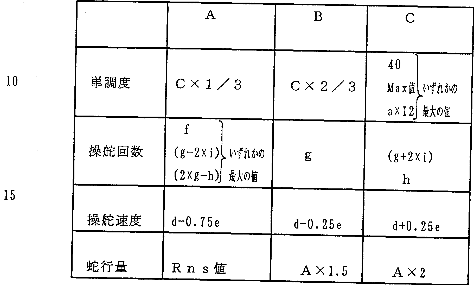
( 1 ) 単調度についてのメンバーシップ関数の形状は、 第 1図の 居眠り運転警報装置 S 1で説明したと同様に設定され、 実例は上述 の第 1 6図に示した。 (1) The shape of the membership function for monotonicity is set in the same manner as described for the drowsy driving alarm S1 in FIG. 1, and an example is shown in FIG. 16 described above.
(2) 操舵速度についてのメンバーシップ関数の形状は、 "速い' "中間" "遅い" の 3クラスに区切られておリ、 偏差 eに定数 0. 7 5が乗算され、 その乗算値を平均値 dから減算した値 (= d— 0. (2) The shape of the membership function for the steering speed is divided into three classes: "fast", "medium", and "slow". The deviation e is multiplied by a constant 0.75, and the multiplied value is averaged. Value subtracted from value d (= d— 0.
7 5 e ) が区切リ値 Aと決定される。 偏差 eに定数 0. 2 5が乗算 され、 その乗算値を平均値 dから減算した値 (= d— 0. 2 5 e) が区切リ値 Bと決定される。 偏差 eに定数 0. 2 5が乗算され、 そ の乗算値を平均値 dに加算した値 (= d + 0. 2 5 e ) が区切リ値 Cと決定される。 実例を第 2 9図に示す。 7 5 e) is determined as the separation value A. The deviation e is multiplied by the constant 0.25, and the value obtained by subtracting the multiplied value from the average value d (= d-0.25 e) is determined as the delimiter value B. The deviation e is multiplied by the constant 0.25, and the value obtained by adding the multiplied value to the average value d (= d + 0.25 e) is determined as the delimiter value C. An example is shown in Figure 29.
(3) 操舵回数についてのメンバーシップ関数の形状は、 "多い' "中間" "少ない" の 3クラスに区切られておリ、 まず、 各操舵回 数 Mの最小値 f 、 平均値 g、 最大値 h、 標準偏差 iが求められる。 ここで、 f または ( g _ 2 X i ) または ( 2 X g— h ) のうち、 最 大のものが区切リ値 Aに決定される。 gが区切リ値 Bと決定される c ( g + 2 X i ) または hのうち、 最小のものが区切リ値 Cと決定さ れる。 実例を第 30図に示す。 (3) The shape of the membership function for the number of steerings is First, the minimum value f, average value g, maximum value h, and standard deviation i of each steering frequency M are obtained. Here, the largest one of f or (g_2Xi) or (2Xg—h) is determined as the delimiter value A. The smallest one of c (g + 2 X i) or h for which g is determined to be the separation value B is determined to be the separation value C. An example is shown in FIG.
(4) 蛇行量についてのメンバーシップ関数の形状は、 第 1図の 居眠リ運転警報装置 S 1で説明したと同様に設定され、 実例は上述 の第 1 9図に示した。 (4) The shape of the membership function for the meandering amount is set in the same manner as described for the drowsy driving alarm S1 in FIG. 1, and an actual example is shown in FIG. 19 described above.
なお、 フアジィ推論の基準値である各メンバーシップ関数の区切 リ値の設定処理が終了し、 覚醒度の判定処理に入ってからも単調度 と操舵回数と操舵速度に関しては、 M i n、 Ma xの値が更新され た都度その値を反映し、 蛇行量に関しては基準値設定が終了したら その後、 変更せずに使用する。 Note that even after the process of setting the demarcation value of each membership function, which is the reference value of fuzzy inference, is completed and the process of determining the arousal level is started, the monotonicity, the number of times of steering, and the steering speed are still in Min, Max x Each time the value is updated, the value is reflected, and the meandering amount is used without changing after the reference value is set.
そして、 これらメンバーシップ関数を用いてフアジィ推論が実行 され、 運転者の覚醒度が求められる (ステップ 1 36 a ) 。 以下、 このフアジィ推論について説明する。 Then, fuzzy inference is performed using these membership functions, and the degree of awakening of the driver is obtained (step 136a). Hereinafter, this fuzzy inference will be described.
現時点の単調度 T (カウンタ 1 9の値) と第 1 7図のメンバーシ ップ関数とから、 単調度のフアジィ変換グレードが算出される。 例えば、 単調度丁が " 20. 5 7" の場合、 その単調度 Tは第 1 From the current monotonicity T (the value of the counter 19) and the membership function in Fig. 17, the fuzzy conversion grade of the monotonicity is calculated. For example, if the monotonic degree is "20.5 7", its monotonicity T is the first
7図に示すように 2つのクラス "中間" "低い" に対応し、 2つの フアジィ変換グレード " 0. 76" "0. 24" が算出される。 ステップ 1 35 a_,で求められた所定時間当たリの各操舵の操舵 速度の平均値 dと第 29図のメンバーシップ関数とから、 操舵操舵 速度のフアジィ変換グレードが算出される。 . As shown in Fig. 7, two fuzzy conversion grades "0.76" and "0.24" are calculated corresponding to the two classes "medium" and "low". Step 1 35 a _, in the average value of the steering speed of each steering Li per predetermined time determined d and the membership function of Figure 29, Fuajii conversion grade steering steering speed is calculated. .
たとえば、 操舵速度の平均値が "5. 54 d e gZ秒" の場合、 その平均値は第 29図に示すように 1つのクラス "遅い" に対応し. For example, if the average value of the steering speed is "5.54 de gZ seconds", the average value corresponds to one class "slow" as shown in Fig. 29.
1つのフアジィ変換グレード " 1. 0" が算出される。 One fuzzy conversion grade "1.0" is calculated.
ステップ 1 35 a-2で求められた所定時間当たりの操舵回数 Nと 第 30図のメンバーシップ関数とから、 操舵回数のフアジィ変換グ レ一ドが算出される。 たとえば、 操舵回数が "9. 0回 Z秒" の場合、 その操舵回数は 第 30図に示すように 1つのクラス "少ない" に対応し、 1つのフ アジィ変換グレード " 1. 0" が算出される。 Step 1 35 a - from the steering count per predetermined time obtained N and the membership function of Figure 30 at 2, Fuajii conversion grayed, single de steering count is calculated. For example, if the number of times of steering is “9.0 times Z seconds”, the number of times of steering corresponds to one class “less” as shown in Fig. 30, and one fuzzy conversion grade “1.0” is calculated. Is done.
ステップ 1 34で求められた所定時間の蛇行量の平均値 R n 1と 第 1 9図のメンバーシップ関数とから、 蛇行量のフアジィ変換ダレ 一ドが算出される。 From the mean value R n1 of the meandering amount for a predetermined time obtained in step 134 and the membership function of FIG. 19, a fuzzy transformation dale of the meandering amount is calculated.
たとえば、 蛇行量が "20. 6 " の場合、 その蛇行量は第 1 9図 に示すように、 2つのクラス "中間" "大きい" に対応し、 2つの フアジィ変換グレー ド " 0. 95" "0. 05" が算出される。 メモリ 21にはさらに、 第 3 1図に示す制御ルールのフォーマツ トが記憶されておリ、 その制御ルールに対して算出された各フアジ ィ変換グレードが当て嵌められることによリ、 必要量であるところ の覚醒度のクラスが求められる。 For example, if the meandering amount is "20.6", the meandering amount corresponds to two classes "middle" and "large" as shown in Fig. 19, and two fuzzy transformation grades "0.95" "0. 05" is calculated. The memory 21 further stores the format of the control rule shown in FIG. 31, and by applying each of the fuzzy conversion grades calculated for the control rule, A certain arousal class is required.
この場合、 4つのフアジィ変換グレードが算出されておリ、 当て 嵌めの該当箇所を第 3 1図においてアンダーラインで示し、 当て嵌 めらる数値データを第 32図に示している。 In this case, four fuzzy conversion grades have been calculated, and the relevant locations of the fit are indicated by underlines in FIG. 31, and the numerical data to be fit are shown in FIG.
単調度、 操舵速度、 操舵回数及び蛇行量の 4項目について、 ファ ジィ変換グレードがすべて零でないクラスは " 4" "3. 5" "3, "2. 5 " の 4つである。 For the four items of monotonicity, steering speed, number of times of steering, and meandering amount, the classes whose fuzzy conversion grades are not all zero are "4", "3.5", "3", and "2.5".
そして、 クラス "4" に対応する各項目のフアジィ変換グレード のうち、 最大値は " 0. 05" である。 クラス " 3. 5" に対応す る各項目のフアジィ変換グレードのうち、 最大値は " 0. 76" で ある。 クラス "3" に対応する各項目のフアジィ変換グレードのう ち、 最大値は "0. 05" である。 クラス " 2. 5" に対応する各 項目のフアジィ変換グレードのうち、 最大値は " 0. 24" である c また、 後件部であるところの覚醒度について、 第 3 3図に示す 9 クラス、 三角形、 必要幅 " 1ないし 5" のメンバーシップ関数が用 意され、 それがメモリ 2 1に記憶されている。 And the maximum value of fuzzy conversion grade of each item corresponding to class "4" is "0.05". Of the fuzzy conversion grades for each item corresponding to class "3.5", the maximum value is "0.76". Of the fuzzy conversion grades of each item corresponding to class "3", the maximum value is "0.05". Class "2.5" out of Fuajii conversion grade of each item corresponding to the maximum value c also is "0.24", the alertness where a consequent, 9 classes shown in the third Figure 3 A membership function with a triangle, a required width of "1 to 5" is provided and it is stored in memory 21.
この覚醒度のメンバーシップ関数に対し、 抽出された各クラスご とのフアジィ変換グレードが第 3 3図に斜線で示すごとぐ、 当て嵌 められ、 かつ、 斜線部分の重心が計算されることにより、 覚醒度 X ( = " 3 . 3 " ) が求められる。 これでフアジィ推論の終了である こう して、 覚醒度 Xが求まると、 それが表示器 6で表示される (ステップ 1 3 7 ) 。 この表示を見ることによリ、 運転者は自身の 運転状態を把握することができる。 また、 同乗者は運転者が居眠り しないように、 運転者に話しかけたり、 注意を与えたり、 適切な処 置をとることができる。 With respect to this membership function of arousal level, the extracted fuzzy transformation grade for each class is fitted as shown by the shaded area in Fig. 33, and the center of gravity of the shaded area is calculated. Awakening X (= "3.3"). This is the end of fuzzy inference. Thus, when the arousal level X is obtained, it is displayed on the display 6 (step 13 7). By looking at this display, the driver can grasp his driving condition. Passengers can also talk to, give attention to, and take appropriate action to prevent the driver from falling asleep.
この後、 運転停止で無い限リ、 覚醒度判定時間 t 3が強制的に 6 0秒にセッ トされ (ステップ 1 3 9 ) 、 ステップ 1 1 6に戻リ、 運 転停止でシステム停止となる。 Thereafter, not in shutdown Kirill, the awareness determination time t 3 forcibly be set to 6 0 seconds (Step 1 3 9), the system stops return, in OPERATION stop Step 1 1 6 .
この後、 居眠リ運転警報装置 S 1 と同様にコントロールュニッ ト After that, the control unit is operated in the same way as the drowsy driving alarm S1.
4 a内の報知部 Fが第 2 2図のフローチャートに示したと同様に覚 醒度 Xのレベルに応じて覚醒器 7 a, 7 b , 7 c, 7 dを選択的に 駆動し、 覚醒度 Xに応じたレベルの覚醒作用を運転者に与えること により、 運転者の居眠リを未然に防ぐことが出来、 安全性が向上す る。 The notification unit F in 4a selectively drives the wake-up devices 7a, 7b, 7c, and 7d according to the level of the wakefulness X in the same manner as shown in the flowchart of FIG. By giving the driver a wakeful action at a level corresponding to X, it is possible to prevent the driver from falling asleep, thereby improving safety.
このように、 第 2実施例としての居眠リ運転警報装置 S 2は第 1 図の居眠リ運転警報装置 S 1 と同様の作用効果が得られ、 特に、 居 眠リ運転につながるステアリング操作 (ステアリング操作検出部 B aから操舵回数 M、 操舵速度 d ) の特徴と蛇行量をフアジィ推論の 入力とすると共に、 運転者毎の個人レベルの運転操作データをファ ジィ推論の基準値として盛リ込むようにしたので、 運転者の居眠り を木目細かく的確に、 しかも、 常に把握出来、 信頼性にすぐれたも のとなる。 As described above, the drowsy driving alarm S2 according to the second embodiment has the same operation and effect as the dozing driving alarm S1 in FIG. 1, and particularly, the steering operation leading to the drowsy driving is performed. The characteristics of the steering frequency M and the steering speed d from the steering operation detector Ba and the meandering amount are input to fuzzy inference, and individual-level driving operation data for each driver is used as a reference value for fuzzy inference. As a result, the driver's falling asleep can be accurately and accurately grasped at all times, and the reliability is excellent.
上述のところにおいて、 第 2実施例の居眠リ運転警報装置 S 2の ステアリング操作検出部 B aはステアリング操作量と して操舵回数 M、 操舵速度 dを用いたが、 これら何れか一方に代えて、 ステップ 1 2 6 で処理している無操作時間 t 4をもちいてフアジィ変換グ レードの一つを設定するように構成しても良い。 この場合、 例えば, 無操作時間 t と第 3 4図のメンバーシップ関数とから、 無操作時 間のフアジィ変換グレードが算出され、 その他の操舵回数 M、 操舵 速度 dの何れか一方、 単調度及び蛇行量の各フアジィ変換グレード が算出され、 以下同様に処理され、 覚醒度 Xを推論できる。 この場 合も第 2実施例としての居眠リ運転警報装置 S 2と同様の作用効果 が得られる。 In the above description, the steering operation detection unit Ba of the drowsy driving alarm device S2 of the second embodiment uses the number of steering operations M and the steering speed d as the steering operation amount. Te, may be configured to set one of Fuajii conversion grade using a non-operation time t 4 when being processed in step 1 2 6. In this case, for example, the fuzzy conversion grade during the no-operation time is calculated from the no-operation time t and the membership function in FIG. 34, and one of the other number of times of steering M and the steering speed d, the monotonicity and Each fuzzy conversion grade of meandering amount Is calculated, and the same processing is performed in the following, so that the arousal level X can be inferred. In this case, the same operation and effect as the drowsy driving alarm S2 as the second embodiment can be obtained.
第 3 5図には本発明の第 3の実施例を示した。 FIG. 35 shows a third embodiment of the present invention.
この第 3実施例としての居眠り運転警報装置 S 3は第 1図の居眠 り運転警報装置 S 1 と比較し、 カメラ 2及びそれに接続される画像 処理装置 3を備えず、 居眠り運転警報用のコントロールュニッ ト 4 b内に蛇行量演算部 C 3を備えず、 運転者の覚醒度を推定するファ ジィ推論部 D bの機能が相違する点以外は同様の構成を採リ、 ここ では同一部材には同一符号を付し、 同一構成部分の重複説明を略し, 相違点部分を主に説明する。 The drowsy driving warning device S 3 as the third embodiment is different from the drowsing driving warning device S 1 of FIG. 1 in that it does not include the camera 2 and the image processing device 3 connected thereto, and The control unit 4b does not include the meandering amount calculation unit C3, and adopts the same configuration except that the function of the fuzzy inference unit Db for estimating the arousal level of the driver is different. The same reference numerals are given to the members, the same components are not described repeatedly, and the differences are mainly described.
コントロールュニット 4 bはその制御部 8 bに、 第 1図のコント ロールュュッ ト 4と同様に自動車の各種操作手段の操作を検知する ためのセンサを接続され、 しかも、 コントロールユニット 4で説明 したと同様の運転操作検出部 Aとステアリング操作検出部 B及び報 知部 Fとしての機能を備え、 これらの説明は略す。 The control unit 4b is connected to the control unit 8b of a sensor for detecting the operation of various operation means of the vehicle similarly to the control unit 4 of FIG. 1, and furthermore, the control unit 4 has been described. It has the same functions as the driving operation detecting unit A, the steering operation detecting unit B, and the notification unit F, and a description thereof will be omitted.
更に、 コントロールユニット 4 bは基準値設定部 E bと、 運転者 の覚醒度を推定するフアジィ推論部 D bとしての機能を備える。 ここで基準値設定部 E bは、 運転開始から一定時間の初期運転に 関して働くもので、 次の ( 1 ) 〜 (4 ) 区分の機能を備える。 Further, the control unit 4b has a function as a reference value setting unit Eb and a function as a fuzzy inference unit Db for estimating the arousal level of the driver. Here, the reference value setting section Eb works for the initial operation for a certain period of time from the start of operation, and has the following functions of (1) to (4).
( 1 ) 運転開始から一定時間 t s lを初期運転として設定する。 (1) Set a fixed time t sl from the start of operation as the initial operation.
( 2 ) 各種操作手段のうちステアリングを除く少なく とも 1つが操 作されたとき、 その操作手段に対応する重み付け値 n iをメモリ 2 1から読み出す。 (2) When at least one of the various operation means except the steering is operated, the weight value ni corresponding to the operation means is read from the memory 21.
( 3 ) 読出される重み付け値 n iをカウンタ 1 9で加算し (n =∑ n i ) 、 加算値 nを初期運転中の全操作回数 N 0として保持する。 ここで、 重み付け値 n iを加算するのは、 実際に起こる率は低いと 思われるが、 複数の操作手段が同時に操作される場合への対応であ る。 (3) The read weight value n i is added by the counter 19 (n = ∑n i), and the added value n is held as the total number of operations N 0 during the initial operation. Here, the addition of the weighting value ni is considered to be a case where the rate of actual occurrence seems to be low, but corresponds to the case where a plurality of operating means are operated simultaneously.
( 4 ) 初期運転の終了時、 全操作回数 N o、 操舵量 S Qの平均値 S (4) At the end of the initial operation, the total number of operations No, the steering amount S Q average value S
Q mをそれぞれ基準値としてメモリ 2 1に記憶する。 また、 フアジィ推論部 D bは初期運転の経過後働く もので、 次の ( 1 ) の機能を備える。 Q m is stored in the memory 21 as a reference value. The fuzzy inference unit Db works after the initial operation, and has the following function (1).
( 1 ) 運転操作検出部 Aからの単調度 T、 ステアリング操作検出部 Βから操舵量 S Qに対応するメンバーシップ関数に基づいて運転者 の覚醒度を推定する。 (1) Estimate the awakening degree of the driver based on the monotonicity T from the driving operation detection unit A and the membership function corresponding to the steering amount SQ from the steering operation detection unit Β.
なお、 このフアジィ推論部 D bは 1分間毎に判定サイクルを実行 して覚醒度を更新するが、 各判定サイクルで使用すデータは各判定 サイクル直前の 1 0分間の時間範囲で取リ込まれ、 そのデータ範囲 は 1分ずつずらせて順次取リ込まれることとなる。 The fuzzy inference unit Db executes a judgment cycle every minute to update the alertness, but the data used in each judgment cycle is taken in the time range of 10 minutes immediately before each judgment cycle. However, the data range is shifted one minute at a time and is taken in sequentially.
次に、 第 3実施例としての居眠り運転警報装置 S 3の作動を第 3 Next, the operation of the drowsy driving alarm device S3 as the third embodiment is described in the third embodiment.
6図乃至第 3 8図のフローチヤ一トを参照しながら説明する。 なお、 ここでのフローチヤ一トは、 居眠リ運転警報装置 S 1の第 9図乃至 第 1 2図のフローチヤ一トと同一構成部分が多く、 ここでは同一ス テツプには同一ステップ番号を付し、 相違するステップには 「b」 記号を追加して付し、 更に、 重複説明は簡略化する。 This will be described with reference to the flowcharts of FIGS. 6 to 38. Note that the flowchart here has many components that are the same as those of the flowcharts of FIGS. 9 to 12 of the drowsy driving alarm S1. Here, the same steps are given the same step numbers. In addition, different steps are marked with an additional “b” symbol, and duplicate explanations are simplified.
ィダニッシヨンスィツチがオンされてエンジンが始動されると、 コントロールュニッ ト 4 bがシステム起動し、 検知車速 Vが一定値 V 1を越えると初期運転時間 t ,のカウントが開始される (ステツ プ 1 0 1〜 1 0 2 ) 。 When the ignition switch is turned on and the engine is started, the control unit 4b starts the system, and when the detected vehicle speed V exceeds a certain value V1, counting of the initial operation time t, is started ( Step 101-102).
運転中、 ステアリングリング操作を除く少なく とも 1つの操作部 材操作が実行されると、 その操作手段に対した重み付け値 n iが読. 出され、 重み付け値 n iがカウンタ 1 9で加算され、 加算値 nが初 期運転中の全操作回数 N o として保持される (ステップ 1 0 4〜 1 0 7 ) 。 When at least one operation member operation except for the steering ring operation is performed during driving, a weight value ni for the operation means is read out, the weight value ni is added by the counter 19, and the added value is calculated. n is held as the total number of operations No during the initial operation (steps 104 to 107).
操舵があると、 その操舵毎に、 カウンタ 2 0が 「 1」 づっ加算さ れて操舵回数 Mがメモリ 2 1に順次記憶される (ステップ 1 0 8, 1 0 9 ) 。 When steering is performed, the counter 20 is incremented by "1" for each steering operation, and the number of steerings M is sequentially stored in the memory 21 (steps 108, 109).
M = M + 1 M = M + 1
初期運転時間 t ,がー定時間 t s l (例えば 2 0分) を越えると ( ステップ 1 1 1 ) 、 そこで初期運転の終了と成る。 If the initial operation time t, exceeds the fixed time t sl (for example, 20 minutes) (step 1 1 1), the initial operation ends there.
ステップ s 1 1 3に達すると、 メモリ 2 1に記憶されている各操 舵角 Qデータに基づき操舵量 SQを (2) 式より求める。 その操舵 量 S Qが読出され、 初期運転時の操舵量の加算値 S Qmが算出され る。 When step s 1 1 3 is reached, each operation stored in memory 21 Based on the steering angle Q data, the steering amount SQ is obtained from equation (2). The steering amount SQ is read, and an added value S Qm of the steering amount at the time of the initial operation is calculated.
そして、 カウンタ 1 9の初期運転時の全操作回数 N o、 初期運転 時の操舵量 (標準値) SQmがそれぞれ基準値としてメモリ 2 1に 保持される (ステップ 1 1 4 b) 。 Then, the total number of operations No of the counter 19 in the initial operation and the steering amount (standard value) SQm in the initial operation are respectively stored in the memory 21 as reference values (step 114b).
初期運転の開始後、 ステップ 1 1 5ではタイマ 1 8で運転時間 t 2、 覚醒度判定用時間 t 3のカウントが開始される。 After the start of the initial operation, the timer 18 starts counting the operation time t 2 and the arousal level determination time t 3 in step 1 15.
ところで、 車速 Vが一定値 V 1を下回った場合、 それまで蓄積さ れていたメモリ 21内の操舵量データがク リアされる (ステップ 1 By the way, when the vehicle speed V falls below the fixed value V1, the steering amount data stored in the memory 21 which has been stored so far is cleared (step 1).
30, 1 3 1 ) o 30, 1 3 1) o
また、 車速 Vが零まで下がると、 覚醒度の表示がオフされる (ス テツプ 1 32, 1 33) 。 ただし、 この場合、 単調度 Tは保持され る。 When the vehicle speed V decreases to zero, the display of the alertness level is turned off (steps 132, 133). However, in this case, the monotonicity T is maintained.
ステップ 1 21では操蛇角 Qデータに基づき上述の (2) 式よリ 操舵量 S Qが求められ、 操舵量データがメモリ 2 1に蓄積される。 In step 121, the steering amount SQ is obtained from the steering angle Q data according to the above equation (2), and the steering amount data is stored in the memory 21.
ざらに、 カウンタ 1 9で一定値 T oが積算され、 単調度 Tが求め られる (ステップ 1 22) 。 Roughly, a constant value To is accumulated by the counter 19 to obtain a monotonicity T (step 122).
T = T + T o T = T + To
この一定値 T oの積算は、 制御サイクルタイムであるところの 1 The integration of this constant value To is 1 which is the control cycle time.
/ 1 0秒ごとに繰返し実行される。 / Executed repeatedly every 10 seconds.
運転中、 ステアリング操作を除く少なく とも 1つの操作が実行さ れると (ステップ 1 23の Y e s ) 、 その操作手段に対して予め定 められている重み付け値 n iがメモリ 2 1から読出され、 その重み 付け値 n iが加算される (ステップ 1 24) 。 そして、 加算値 nが 運転中の全操作回数 Nとしてカウンタ 1 9で積算される (ステップ 1 25) 。 During driving, when at least one operation other than the steering operation is performed (Yes in step 123), a predetermined weight value ni for the operation means is read from the memory 21 and the corresponding weight value ni is read from the memory 21. The weight ni is added (step 124). Then, the added value n is integrated by the counter 19 as the total number of operations N during operation (step 125).
η =∑ n 1 η = ∑ n 1
N = N+ n N = N + n
運転時間 t 2がこの全操作回数 Nで除算され、 初期運転経過後の 各操作間の時間経過の平均値 〔= t 2/N〕 が求められる。 この時間経過の平均値に 1秒当たりの単調度増加量 (= 1 0 · T 0 ) が乗算され、 これに読出される重み付け値の加算値 nが乗算さ れ、 現時点の操作に基づく単調度解消量 〔= ( t 2/Ν) · 1 0 · T o · n〕 が求められる (ステップ 1 26) 。 Operating time t 2 is divided by the total number of operations N, the average value of the time lapse between each operation after the initial operation elapsed [= t 2 / N] is obtained. The average value over time is multiplied by the monotonicity increase per second (= 10T0), and multiplied by the added value n of the read weight value, to obtain the monotonicity based on the current operation. The amount of cancellation [= (t 2 / Ν) · 10 · T o · n] is determined (step 126).
この単調度解消量だけカウンタ 1 9の積算値が減じられ (ステツ プ 1 2 7) 、 単調度 Tが補正される。 The integrated value of the counter 19 is reduced by this monotonic degree cancellation amount (step 127), and the monotonicity T is corrected.
T = T— 〔 ( t 2/N) · 1 0 · T o · n〕 T = T— [(t 2 / N) · 10 · T o · n]
したがって、 単調度 Tは、 第 1 4図の実験データから判るように, 操作がなければ増大を続け、 操作がなされるごとにその操作に応じ 分だけ解消される。 Therefore, as can be seen from the experimental data in FIG. 14, the monotonicity T continues to increase if there is no operation, and is canceled by an amount corresponding to the operation each time the operation is performed.
単調度 Τが負の値に成った場合 (ステップ 1 27の Y e s ) 、 単 調度 Tは零に修正される (ステップ 1 28) 。 If the monotonicity Τ becomes negative (Y e s in step 127), the monotonicity T is corrected to zero (step 128).
こうして、 覚醒度判定時間 t 3が所定時間に達するまで (ステツ プ 1 29) 、 単調度 Tの計数、 操舵量 S Qの蓄積が繰リ返される。 覚醒度判定時間 t 3が所定時間を超えると (ステップ 1 29の Y e s ) , その所定時間に蓄えられた操舵角 Q nデータに基づき、 最 新の所定時間における各操舵量が加算され S Q n (=∑Qn) がメ モリ 2 1にス トァされる (ステップ 1 3 5) 。 Thus, until the awareness determination time t 3 reaches a predetermined time (Sutetsu flop 1 29), the counting of monotonousness T, accumulation of steering amount SQ is repeated. When awareness determination time t 3 exceeds a predetermined time (Y es of Step 1 29), based on the steering angle Q n data stored in the predetermined time, it is subject to the steering amount of a predetermined time the latest SQ n (= ∑Qn) is stored in memory 21 (step 135).
ステップ 1 36 bに達すると、 覚醒度 Xの推論を行なう。 Step 1 When 36b is reached, the arousal level X is inferred.
まず、 メモリ 2 1に記憶されていた単調度 T、 操舵量 SQについ てのメンバーシップ関数が呼び出される。 First, the membership functions for the monotonicity T and the steering amount SQ stored in the memory 21 are called.
これらメンバーシップ関数は共に第 1 5図に示すように、 3クラ ス、 三角型、 しかも前件部が A、 B、 Cの 3つに区切られたもので ぁリ、 基本的には、 初期運転で得られた各基準値 (単調度 T、 操舵 量 SQm、 全操作回数 No) および初期運転の経過後に得られた全 操作回数 Nに応じてそれぞれ形状が決定される。 As shown in Fig. 15, both of these membership functions are 3 classes, triangular, and the antecedent is divided into three parts A, B, and C. The shape is determined according to each reference value (monotonicity T, steering amount SQm, total number of operations No.) obtained during operation and the total number of operations N obtained after the initial operation.
具体的には次の表 3に示すような関係に基づいて区切リ値 A, B, Cが求められている。 【表 3】 Specifically, the separation values A, B, and C are determined based on the relationships shown in Table 3 below. [Table 3]
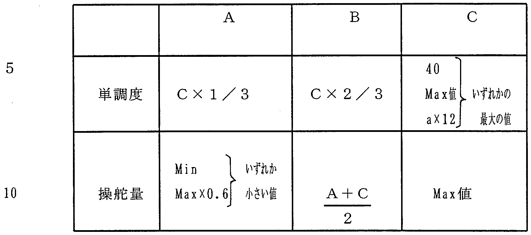
( 1 ) 単調度についてのメンバーシップ関数の形状は、 第 1図の 居眠リ運転警報装置 S 1で説明したと同様に設定され、 実例は上述 の第 1 7図に示した。 (1) The shape of the membership function for monotonicity is set in the same manner as described for the drowsy driving alarm S1 in FIG. 1, and an example is shown in FIG. 17 described above.
(2) 操舵量についてのメンバーシップ関数の形状は、 第 1図の 居眠リ運転警報装置 S 1で説明したと同様に設定され、 実例は上述 の第 1 8図に示した。 (2) The shape of the membership function for the steering amount is set in the same manner as described for the drowsy driving alarm S1 in FIG. 1, and an actual example is shown in FIG. 18 described above.
なお、 フアジィ推論の基準値である各メンバーシップ関数の区切 リ値の設定処理が終了し、 覚醒度の判定処理に入ってからも単調度 と操舵量に関しては、 M i n、 M a Xの値が更新された都度その値 を反映させて使用する。 Note that the monotonicity and the amount of steering remain the same for the values of Min and Max even after the process of setting the demarcation value of each membership function, which is the reference value of fuzzy inference, is completed and the process of determining arousal level is started Each time is updated, its value is used.
そして、 これらメンバーシップ関数を用いてフアジィ推論が実行 される。 Then, fuzzy inference is performed using these membership functions.
現時点の単調度 T (カウンタ 1 9の値) と第 1 7図のメンバーシ ップ関数とから、 単調度のフアジィ変換グレードが算出される。 例えば、 単調度丁が " 20. 5 7" の場合、 その単調度 Tは第 1 7図に示すように 2つのクラス "中間" "低い" に対応し、 2つの フアジィ変換グレード " 0. 76 " "0. 24" が算出される。 ステップ 1 35で求められた所定時間当たリの操舵量 SQnと第 From the current monotonicity T (the value of the counter 19) and the membership function in Fig. 17, the fuzzy conversion grade of the monotonicity is calculated. For example, if the monotonic degree is “20.5 7”, the monotonicity T corresponds to two classes “middle” and “low” as shown in FIG. 17 and two fuzzy conversion grades “0.76” "" 0.24 "is calculated. Step 1 The steering amount SQn corresponding to the predetermined time
1 8図のメンバーシップ関数とから、 操舵量のフアジィ変換グレー ドが算出される。 18 From the membership function shown in Fig. 8, the steering conversion gray Is calculated.
たとえば、 操舵量の平均値が " 645 2" の場合、 その平均値は 第 1 8図に示すように 2つのクラス "多い" "中間" に対応し、 2 つのフアジィ変換グレード " 0. 86" "0. 14" が算出される ( メモリ 21にはさらに、 第 39図に示す制御ルールのフォーマッ トが記憶されておリ、 その制御ルールに対して算出された各フアジ ィ変換グレードが当て嵌められることによリ、 必要量であるところ の覚醒度のクラスが求められる。 For example, if the average value of the steering amount is "645 2", the average value corresponds to the two classes "many" and "middle" as shown in Fig. 18, and the two fuzzy conversion grades "0.86""0.14" is calculated (the memory 21 further stores the format of the control rule shown in FIG. 39, and each fuzzy conversion grade calculated for the control rule is applied. Therefore, a class of arousal level, which is a necessary amount, is required.
この場合、 2つのフアジィ変換グレードが算出されておリ、 当て 嵌めの該当箇所を第 39図においてアンダーラインで示し、 当て嵌 めらる数値 (フアジィ変換グレード) データを第 40図に示してい る。 In this case, two fuzzy conversion grades have been calculated, and the relevant locations of the fits are underlined in FIG. 39, and the values of the fits (fuzzy conversion grades) are shown in FIG.
単調度、 操舵量の 2項目について、 フアジィ変換グレードがすべ て零でないクラスは " 3 " " 2. 5 " " 1. 5 " " 1 " の 4つであ る。 Regarding the two items of monotonicity and steering amount, there are four classes with non-zero fuzzy conversion grades: "3", "2.5", "1.5", and "1".
そして、 クラス "3" に対応する各項目のフアジィ変換グレード の値は "0. 14" である。 クラス " 2. 5" に対応する各項目の フアジィ変換グレードの値は " 0. 14" である。 クラス " 1. 5' に対応する各項目のフアジィ変換グレードの値は "0. 76" であ る。 The value of the fuzzy conversion grade for each item corresponding to class "3" is "0.14". The fuzzy conversion grade value of each item corresponding to class "2.5" is "0.14". The fuzzy conversion grade value of each item corresponding to class "1.5 '" is "0.76".
クラス "1 " に対応する各項目のフアジィ変換グレードのうち、 最大値は "0. 24" である。 The maximum value of the fuzzy conversion grade of each item corresponding to class "1" is "0.24".
また、 後件部であるところの覚醒度について、 第 4 1図に示す 9 クラス、 三角形、 必要幅 " 1ないし 5" のメンバーシップ関数が用 意され、 それがメモリ 2 1に記憶されている。 Regarding the degree of arousal in the consequent part, a membership function with nine classes, triangles, and the required width "1 to 5" shown in Fig. 41 is prepared and stored in the memory 21. .
この覚醒度のメンバーシップ関数に対し、 抽出された各クラスご とのフアジィ変換グレードが第 4 1図に斜線で示すごとぐ、 当て嵌 められ、 かつ、 斜線部分の重心が計算されることにより、 覚醒度 X (= " 1. 6 " ) が求められる。 これでフアジィ推論の終了である c こう して、 覚醒度 Xが求まると、 それが表示器 6で表示される (ステップ 1 37) 。 この表示を見ることによリ、 運転者は自身の 運転状態を把握することができる。 また、 同乗者は運転者が居眠リ しないように、 運転者に話しかけたリ、 注意を与えたり、 適切な処 置をとることができる。 The extracted fuzzy transformation grade for each class is applied to the membership function of the arousal level as shown by the shaded area in Fig. 41, and the center of gravity of the shaded area is calculated. Arousal level X (= "1.6") is required. This is the end of the fuzzy inference c. Thus, when the arousal level X is obtained, it is displayed on the display 6 (step 137). By looking at this display, the driver The operating state can be grasped. In addition, the passenger can talk to the driver, give caution, and take appropriate measures to prevent the driver from falling asleep.
この後、 運転停止で無い限リ、 覚醒度判定時間 t 3が強制的に 6 0秒にセットされ (ステップ 1 3 9 ) 、 ステップ 1 1 6に戻リ、 運 転停止でシステム停止となる。 Thereafter, not in shutdown Kirill, the awareness determination time t 3 forcibly set to 6 0 seconds (Step 1 3 9), the system stops Step 1 1 6 return, in OPERATION stop.
この後、 居眠り運転警報装置 S 3では居眠リ運転警報装置 S 1と 同様にコントロールユニッ ト 4 b内の報知部 Fが第 2 2図のフロー チャートに沿って覚醒度 Xのレベルに応じて覚醒器 7 a , 7 b , 7 c, 7 dを選択的に駆動し、 覚醒度 Xに応じたレベルの覚醒作用を 運転者に与えることによリ、 運転者の居眠りを未然に防ぐことが出 来、 安全性が向上する。 After that, in the drowsy driving alarm device S3, as in the case of the drowsy driving alarm device S1, the notifying section F in the control unit 4b responds to the level of the awakening degree X according to the flow chart of FIG. By selectively driving the wake-up devices 7 a, 7 b, 7 c, and 7 d to give the driver a wake-up action at a level corresponding to the wake-up degree X, it is possible to prevent the driver from falling asleep Since then, safety has improved.
このように、 第 3実施例としての居眠り運転警報装置 S 3は居眠 リ運転警報装置 S 1 と同様に、 運転者の居眠りに対して的確に警報 を発することができ、 しかも、 常に居眠リの程度を把握出来、 信頼 性にすぐれたものとなる。 特に、 カメラ 2や画像処理装置 3等の構 成部材が排除され、 制御も簡素化され、 コス ト低減を図リ易い。 産業上の利用可能性 As described above, the drowsy driving alarm device S 3 as the third embodiment, like the drowsing driving alarm device S 1, can accurately issue an alarm to the driver falling asleep, The degree of reliability can be ascertained, resulting in excellent reliability. In particular, components such as the camera 2 and the image processing device 3 are eliminated, control is simplified, and cost is easily reduced. Industrial applicability
以上のように、 本発明にかかる居眠り運転警報装置は、 乗用車等 を含む多種の自動車に容易に装着でき、 車両の運転者が居眠リ運転 に入リかけた際に警報を発して走行安全性を確保できる装置として その効果を十分に発揮できる。 As described above, the drowsy driving alarm device according to the present invention can be easily mounted on various types of automobiles including passenger cars, and emits an alarm when the vehicle driver starts to fall asleep. The effect can be fully exhibited as a device that can secure the performance.
Claims
Priority Applications (3)
| Application Number | Priority Date | Filing Date | Title |
|---|---|---|---|
| DE4480341A DE4480341B4 (en) | 1993-12-28 | 1994-12-28 | Safety Driving System |
| DE4480341T DE4480341T1 (en) | 1993-12-28 | 1994-12-28 | Safety driving system |
| US08/507,481 US5745031A (en) | 1993-12-28 | 1994-12-28 | Safety driving system |
Applications Claiming Priority (2)
| Application Number | Priority Date | Filing Date | Title |
|---|---|---|---|
| JP5/337407 | 1993-12-28 | ||
| JP33740793 | 1993-12-28 |
Publications (1)
| Publication Number | Publication Date |
|---|---|
| WO1995018433A1 true WO1995018433A1 (en) | 1995-07-06 |
Family
ID=18308348
Family Applications (1)
| Application Number | Title | Priority Date | Filing Date |
|---|---|---|---|
| PCT/JP1994/002292 Ceased WO1995018433A1 (en) | 1993-12-28 | 1994-12-28 | Alarming device for dozing driver |
Country Status (3)
| Country | Link |
|---|---|
| US (1) | US5745031A (en) |
| DE (2) | DE4480341B4 (en) |
| WO (1) | WO1995018433A1 (en) |
Cited By (8)
| Publication number | Priority date | Publication date | Assignee | Title |
|---|---|---|---|---|
| JPH0939601A (en) * | 1995-08-04 | 1997-02-10 | Mitsubishi Motors Corp | Drowsy driving alarm |
| FR2742706A1 (en) * | 1995-12-22 | 1997-06-27 | Peugeot | Monitoring process for observing watchful state of driver to guard against tiredness |
| US5787068A (en) * | 1996-11-07 | 1998-07-28 | Imation Corp. | Method and arrangement for preventing unauthorized duplication of optical discs using barriers |
| JP3039327B2 (en) | 1995-06-30 | 2000-05-08 | 三菱自動車エンジニアリング株式会社 | Vehicle running state detection device and drowsy driving alarm device |
| US7152000B2 (en) | 2004-03-19 | 2006-12-19 | Mitsubishi Fuso Truck And Bus Corporation | Vehicle traveling state determining apparatus |
| US7369942B2 (en) | 2004-03-12 | 2008-05-06 | Mitsubishi Fuso Truck And Bus Corporation | Vehicle traveling state determining apparatus |
| US7388967B2 (en) | 2004-03-26 | 2008-06-17 | Mitsubishi Fuso Truck And Bus Corporation | Vehicle running state judging apparatus |
| JP2013143026A (en) * | 2012-01-11 | 2013-07-22 | Suzuki Motor Corp | Vehicle driver's state detecting system |
Families Citing this family (83)
| Publication number | Priority date | Publication date | Assignee | Title |
|---|---|---|---|---|
| US6822563B2 (en) | 1997-09-22 | 2004-11-23 | Donnelly Corporation | Vehicle imaging system with accessory control |
| US5877897A (en) | 1993-02-26 | 1999-03-02 | Donnelly Corporation | Automatic rearview mirror, vehicle lighting control and vehicle interior monitoring system using a photosensor array |
| US6891563B2 (en) | 1996-05-22 | 2005-05-10 | Donnelly Corporation | Vehicular vision system |
| US7655894B2 (en) | 1996-03-25 | 2010-02-02 | Donnelly Corporation | Vehicular image sensing system |
| US6070098A (en) * | 1997-01-11 | 2000-05-30 | Circadian Technologies, Inc. | Method of and apparatus for evaluation and mitigation of microsleep events |
| JPH1148952A (en) * | 1997-08-06 | 1999-02-23 | Mitsubishi Electric Corp | Vehicle braking system |
| US6236968B1 (en) | 1998-05-14 | 2001-05-22 | International Business Machines Corporation | Sleep prevention dialog based car system |
| US6335689B1 (en) * | 1998-10-16 | 2002-01-01 | Fuji Jukogyo Kabushiki Kaisha | Driver's arousal level estimating apparatus for vehicle and method of estimating arousal level |
| US6060989A (en) * | 1998-10-19 | 2000-05-09 | Lucent Technologies Inc. | System and method for preventing automobile accidents |
| US6163277A (en) * | 1998-10-22 | 2000-12-19 | Lucent Technologies Inc. | System and method for speed limit enforcement |
| GB9903724D0 (en) * | 1999-02-19 | 1999-04-14 | Pearce Philip J | Driver fatigue detector |
| JP3998855B2 (en) * | 1999-05-18 | 2007-10-31 | 三菱電機株式会社 | Dangerous approach prevention device |
| US6167333A (en) * | 1999-08-19 | 2000-12-26 | Lucent Technologies Inc. | Highway information system |
| US6310542B1 (en) | 1999-08-19 | 2001-10-30 | Lucent Technologies Inc. | Cognitive system for a vehicle and its occupants |
| GB2366062A (en) * | 2000-02-18 | 2002-02-27 | Philip John Pearce | Detecting fatigue in machine operator or vehicle driver |
| KR20080080123A (en) * | 2000-09-21 | 2008-09-02 | 아메리칸 캘카어 인코포레이티드 | Technique for operating a vehicle effectively and safely |
| US8990367B2 (en) * | 2006-09-29 | 2015-03-24 | Dell Products L.P. | Consistent binding of shared storage across clustered servers |
| US6894606B2 (en) | 2000-11-22 | 2005-05-17 | Fred Forbes | Vehicular black box monitoring system |
| US20020180608A1 (en) * | 2001-05-04 | 2002-12-05 | Sphericon Ltd. | Driver alertness monitoring system |
| DE10156509B4 (en) * | 2001-11-16 | 2007-12-06 | Audi Ag | Driver assistance system |
| US7039551B2 (en) * | 2002-02-04 | 2006-05-02 | Hrl Laboratories, Llc | Method and apparatus for calculating an operator distraction level |
| ES2391556T3 (en) | 2002-05-03 | 2012-11-27 | Donnelly Corporation | Object detection system for vehicles |
| ES2212888B1 (en) * | 2002-05-21 | 2005-10-01 | INSTITUTO NACIONAL DE TECNICA AEROESPACIAL "ESTEBAN TERRADAS" | SYSTEM AND DEVICE FOR THE PREDICTION IN THE TIME OF THE DEGREE OF CARE OF A DRIVER. |
| DE10238324B4 (en) * | 2002-08-21 | 2014-02-13 | Volkswagen Ag | Method and device for monitoring the driver of a motor vehicle |
| DE10241624A1 (en) * | 2002-09-04 | 2004-04-01 | Volkswagen Ag | Method and device for detecting the level of attention of a vehicle driver |
| US6946965B2 (en) * | 2002-12-30 | 2005-09-20 | Young Thomas W | Driver fatigue detector with automatic deactivation |
| JP4366145B2 (en) * | 2003-08-26 | 2009-11-18 | 富士重工業株式会社 | Driver's alertness estimation device and alertness estimation method |
| DE10351654A1 (en) * | 2003-11-05 | 2005-06-02 | Daimlerchrysler Ag | Active Lane Assistant |
| DE10355221A1 (en) * | 2003-11-26 | 2005-06-23 | Daimlerchrysler Ag | A method and computer program for detecting inattentiveness of the driver of a vehicle |
| JP4370915B2 (en) * | 2004-01-14 | 2009-11-25 | オムロン株式会社 | In-vehicle application selection system and in-vehicle application selection device |
| DE602004012836T2 (en) * | 2004-03-02 | 2009-04-09 | Scania Cv Ab (Publ) | Warning system when leaving the lane |
| JP4225229B2 (en) * | 2004-03-30 | 2009-02-18 | 三菱ふそうトラック・バス株式会社 | Arousal level judgment device |
| US7526103B2 (en) | 2004-04-15 | 2009-04-28 | Donnelly Corporation | Imaging system for vehicle |
| DE102005026479B4 (en) * | 2005-06-09 | 2017-04-20 | Daimler Ag | Method for inattention recognition as a function of at least one driver-individual parameter |
| DE102005026456B4 (en) * | 2005-06-09 | 2017-04-20 | Daimler Ag | Method for detecting fatigue |
| DE102005026457B4 (en) * | 2005-06-09 | 2017-04-20 | Daimler Ag | Method and control unit for driver-individual recognition of inattentiveness of the driver of a vehicle |
| WO2007031964A1 (en) * | 2005-09-15 | 2007-03-22 | Michael Adriaan Diedericks | An aid for detecting drowsiness of a driver of a vehicle |
| JP4497081B2 (en) * | 2005-10-31 | 2010-07-07 | トヨタ自動車株式会社 | Human condition detection device |
| JP2007264883A (en) * | 2006-03-28 | 2007-10-11 | Mitsubishi Fuso Truck & Bus Corp | Arousal level information output device for vehicle |
| JP2008013004A (en) * | 2006-07-04 | 2008-01-24 | Fuji Heavy Ind Ltd | Driving support system with aroma generation |
| WO2008024639A2 (en) | 2006-08-11 | 2008-02-28 | Donnelly Corporation | Automatic headlamp control system |
| JP4985150B2 (en) * | 2007-06-29 | 2012-07-25 | 日産自動車株式会社 | Vehicle driving support device and vehicle including vehicle driving support device |
| US8022831B1 (en) | 2008-01-03 | 2011-09-20 | Pamela Wood-Eyre | Interactive fatigue management system and method |
| US8791825B2 (en) * | 2010-03-11 | 2014-07-29 | Toyota Jidosha Kabushiki Kaishi | Biological state determination device |
| US20130021462A1 (en) * | 2010-03-23 | 2013-01-24 | Aisin Seiki Kabushiki Kaisha | Alertness determination device, alertness determination method, and recording medium |
| US8521357B2 (en) | 2010-04-26 | 2013-08-27 | Nissan North America, Inc. | Impaired operation detection method |
| DE102010039949A1 (en) * | 2010-08-30 | 2012-03-01 | Bayerische Motoren Werke Aktiengesellschaft | Method for detecting missing driver activity on the steering wheel of a motor vehicle |
| DE102010049087A1 (en) * | 2010-10-21 | 2012-04-26 | Gm Global Technology Operations Llc (N.D.Ges.D. Staates Delaware) | Method for assessing driver attention |
| WO2012074935A2 (en) * | 2010-11-29 | 2012-06-07 | Washington State University Research Foundation | Alertness monitoring systems and associated methods |
| DE102011013663A1 (en) * | 2011-03-11 | 2012-09-13 | GM Global Technology Operations LLC (n. d. Gesetzen des Staates Delaware) | Method for assessing driver attention |
| US8577566B2 (en) * | 2011-05-18 | 2013-11-05 | Nissan Motor Co., Ltd. | Driving instability determination device |
| DE102012013546A1 (en) * | 2012-07-05 | 2013-01-24 | Daimler Ag | Method for operating assistance device of vehicle, involves displaying attention level of vehicle rider by bar line display in display area of instrument panel of vehicle |
| US20140358423A1 (en) * | 2013-05-29 | 2014-12-04 | Sony Corporation | Method and apparatus for automatically warning driver to take a break |
| FR3012381B1 (en) * | 2013-10-24 | 2017-08-11 | Peugeot Citroen Automobiles Sa | METHOD FOR MONITORING THE VIGILANCE STATUS OF THE DRIVER OF A MOTOR VEHICLE AND ASSOCIATED SYSTEM |
| BR112017004621A2 (en) | 2014-09-09 | 2018-01-30 | Torvec, Inc. | portable device to monitor fatigue and notify a user, and method for monitoring a user's alertness and notify the user. |
| DE102015206211A1 (en) | 2015-04-08 | 2016-10-13 | Bayerische Motoren Werke Aktiengesellschaft | Warning unit in a vehicle to warn the driver in the event of imminent danger |
| US10238335B2 (en) | 2016-02-18 | 2019-03-26 | Curaegis Technologies, Inc. | Alertness prediction system and method |
| DE102017009353A1 (en) | 2017-10-09 | 2019-04-11 | Daimler Ag | Varfahran for controlling vehicle function |
| CN108032798B (en) * | 2017-12-13 | 2023-06-20 | 辽宁工业大学 | Steering lamp device capable of automatically working during expressway overtaking and control method |
| CN110027605A (en) * | 2018-01-12 | 2019-07-19 | 罗伯特·博世有限公司 | Adjustment wire-controlled steering system is suitable for the control unit and method of automobile driver |
| US11775816B2 (en) | 2019-08-12 | 2023-10-03 | Micron Technology, Inc. | Storage and access of neural network outputs in automotive predictive maintenance |
| US11635893B2 (en) | 2019-08-12 | 2023-04-25 | Micron Technology, Inc. | Communications between processors and storage devices in automotive predictive maintenance implemented via artificial neural networks |
| US11586943B2 (en) | 2019-08-12 | 2023-02-21 | Micron Technology, Inc. | Storage and access of neural network inputs in automotive predictive maintenance |
| US12249189B2 (en) | 2019-08-12 | 2025-03-11 | Micron Technology, Inc. | Predictive maintenance of automotive lighting |
| US11853863B2 (en) | 2019-08-12 | 2023-12-26 | Micron Technology, Inc. | Predictive maintenance of automotive tires |
| US11748626B2 (en) | 2019-08-12 | 2023-09-05 | Micron Technology, Inc. | Storage devices with neural network accelerators for automotive predictive maintenance |
| US11586194B2 (en) | 2019-08-12 | 2023-02-21 | Micron Technology, Inc. | Storage and access of neural network models of automotive predictive maintenance |
| US12061971B2 (en) | 2019-08-12 | 2024-08-13 | Micron Technology, Inc. | Predictive maintenance of automotive engines |
| US11498388B2 (en) | 2019-08-21 | 2022-11-15 | Micron Technology, Inc. | Intelligent climate control in vehicles |
| US10993647B2 (en) | 2019-08-21 | 2021-05-04 | Micron Technology, Inc. | Drowsiness detection for vehicle control |
| US11702086B2 (en) | 2019-08-21 | 2023-07-18 | Micron Technology, Inc. | Intelligent recording of errant vehicle behaviors |
| US12497055B2 (en) | 2019-08-21 | 2025-12-16 | Micron Technology, Inc. | Monitoring controller area network bus for vehicle control |
| US11361552B2 (en) | 2019-08-21 | 2022-06-14 | Micron Technology, Inc. | Security operations of parked vehicles |
| US11042350B2 (en) | 2019-08-21 | 2021-06-22 | Micron Technology, Inc. | Intelligent audio control in vehicles |
| US11693562B2 (en) | 2019-09-05 | 2023-07-04 | Micron Technology, Inc. | Bandwidth optimization for different types of operations scheduled in a data storage device |
| US12210401B2 (en) | 2019-09-05 | 2025-01-28 | Micron Technology, Inc. | Temperature based optimization of data storage operations |
| US11650746B2 (en) | 2019-09-05 | 2023-05-16 | Micron Technology, Inc. | Intelligent write-amplification reduction for data storage devices configured on autonomous vehicles |
| US11436076B2 (en) | 2019-09-05 | 2022-09-06 | Micron Technology, Inc. | Predictive management of failing portions in a data storage device |
| US11409654B2 (en) | 2019-09-05 | 2022-08-09 | Micron Technology, Inc. | Intelligent optimization of caching operations in a data storage device |
| US11435946B2 (en) | 2019-09-05 | 2022-09-06 | Micron Technology, Inc. | Intelligent wear leveling with reduced write-amplification for data storage devices configured on autonomous vehicles |
| US11250648B2 (en) | 2019-12-18 | 2022-02-15 | Micron Technology, Inc. | Predictive maintenance of automotive transmission |
| US11709625B2 (en) | 2020-02-14 | 2023-07-25 | Micron Technology, Inc. | Optimization of power usage of data storage devices |
| US11531339B2 (en) | 2020-02-14 | 2022-12-20 | Micron Technology, Inc. | Monitoring of drive by wire sensors in vehicles |
Citations (3)
| Publication number | Priority date | Publication date | Assignee | Title |
|---|---|---|---|---|
| JPH03219400A (en) * | 1990-01-25 | 1991-09-26 | Matsushita Electric Ind Co Ltd | Traveling direction monitoring device for vehicle |
| JPH0554300A (en) * | 1991-08-22 | 1993-03-05 | Omron Corp | Arousal level detection device |
| JPH0566803A (en) * | 1991-09-06 | 1993-03-19 | Nippon Telegr & Teleph Corp <Ntt> | Optimal fuzzy set representative value autotuning method for neural type robot of small diameter tunnel |
Family Cites Families (15)
| Publication number | Priority date | Publication date | Assignee | Title |
|---|---|---|---|---|
| JPS5321939B2 (en) * | 1974-08-26 | 1978-07-05 | ||
| HU184050B (en) * | 1979-11-29 | 1984-06-28 | Gyoergy Balogh | Method for detecting and checking the decreasing of activity and watchfulness level of driver on vehicles on non-limited way having independent source of power as well as safety device for vehicles of non-limited way |
| US4463347A (en) * | 1980-09-22 | 1984-07-31 | Nissan Motor Company, Ltd. | Drowsiness alarm system for a vehicle |
| US4509040A (en) * | 1981-12-01 | 1985-04-02 | Nissan Motor Company, Limited | Alarm system for preventing an automotive vehicle driver from dozing at the wheel |
| JPS58105844A (en) * | 1981-12-21 | 1983-06-23 | Nissan Motor Co Ltd | Warning device for vehicle |
| JPS58175094A (en) * | 1982-04-06 | 1983-10-14 | 日産自動車株式会社 | Alarm for vehicle |
| JPS59153625A (en) * | 1983-02-18 | 1984-09-01 | Nissan Motor Co Ltd | Dozing-drive detecting apparatus |
| JPS59153624A (en) * | 1983-02-18 | 1984-09-01 | Nissan Motor Co Ltd | Dozing-drive detecting apparatus |
| US4602247A (en) * | 1983-02-18 | 1986-07-22 | Nissan Motor Company, Limited | Method and system for detecting driver fatigue including differentiation of effects of rest periods |
| US4794536A (en) * | 1984-05-24 | 1988-12-27 | Toyoda Koki Kabushiki Kaisha | Steering angle detection device |
| DE3835726A1 (en) * | 1988-10-20 | 1990-04-26 | Waldemar Mueller | Steering wheel contact sensor ring switch for controlling optical/acoustic warning systems, engine shut-off devices and emergency braking devices on motor vehicles of all kinds |
| JP2669031B2 (en) * | 1989-02-28 | 1997-10-27 | 日産自動車株式会社 | Autonomous vehicles |
| JP2600427B2 (en) * | 1990-03-23 | 1997-04-16 | 松下電器産業株式会社 | Traveling lane detection device for vehicles |
| FR2679357B1 (en) * | 1991-07-19 | 1997-01-31 | Matra Sep Imagerie Inf | ON-BOARD DEVICE AND METHOD FOR TRACKING AND MONITORING THE POSITION OF A VEHICLE ON THE ROAD AND DRIVING AID DEVICE INCLUDING APPLICATION. |
| JP3273498B2 (en) | 1997-04-30 | 2002-04-08 | 大八化学工業株式会社 | Method for producing ester compound |
-
1994
- 1994-12-28 WO PCT/JP1994/002292 patent/WO1995018433A1/en not_active Ceased
- 1994-12-28 DE DE4480341A patent/DE4480341B4/en not_active Expired - Fee Related
- 1994-12-28 DE DE4480341T patent/DE4480341T1/en active Pending
- 1994-12-28 US US08/507,481 patent/US5745031A/en not_active Expired - Lifetime
Patent Citations (3)
| Publication number | Priority date | Publication date | Assignee | Title |
|---|---|---|---|---|
| JPH03219400A (en) * | 1990-01-25 | 1991-09-26 | Matsushita Electric Ind Co Ltd | Traveling direction monitoring device for vehicle |
| JPH0554300A (en) * | 1991-08-22 | 1993-03-05 | Omron Corp | Arousal level detection device |
| JPH0566803A (en) * | 1991-09-06 | 1993-03-19 | Nippon Telegr & Teleph Corp <Ntt> | Optimal fuzzy set representative value autotuning method for neural type robot of small diameter tunnel |
Cited By (8)
| Publication number | Priority date | Publication date | Assignee | Title |
|---|---|---|---|---|
| JP3039327B2 (en) | 1995-06-30 | 2000-05-08 | 三菱自動車エンジニアリング株式会社 | Vehicle running state detection device and drowsy driving alarm device |
| JPH0939601A (en) * | 1995-08-04 | 1997-02-10 | Mitsubishi Motors Corp | Drowsy driving alarm |
| FR2742706A1 (en) * | 1995-12-22 | 1997-06-27 | Peugeot | Monitoring process for observing watchful state of driver to guard against tiredness |
| US5787068A (en) * | 1996-11-07 | 1998-07-28 | Imation Corp. | Method and arrangement for preventing unauthorized duplication of optical discs using barriers |
| US7369942B2 (en) | 2004-03-12 | 2008-05-06 | Mitsubishi Fuso Truck And Bus Corporation | Vehicle traveling state determining apparatus |
| US7152000B2 (en) | 2004-03-19 | 2006-12-19 | Mitsubishi Fuso Truck And Bus Corporation | Vehicle traveling state determining apparatus |
| US7388967B2 (en) | 2004-03-26 | 2008-06-17 | Mitsubishi Fuso Truck And Bus Corporation | Vehicle running state judging apparatus |
| JP2013143026A (en) * | 2012-01-11 | 2013-07-22 | Suzuki Motor Corp | Vehicle driver's state detecting system |
Also Published As
| Publication number | Publication date |
|---|---|
| DE4480341B4 (en) | 2005-05-25 |
| DE4480341T1 (en) | 1996-03-21 |
| US5745031A (en) | 1998-04-28 |
Similar Documents
| Publication | Publication Date | Title |
|---|---|---|
| WO1995018433A1 (en) | Alarming device for dozing driver | |
| EP3825981B1 (en) | Warning apparatus and driving tendency analysis device | |
| CN108394414B (en) | Wakefulness determination system and wakefulness determination method | |
| JP3257310B2 (en) | Inattentive driving detection device | |
| US9707971B2 (en) | Driving characteristics diagnosis device, driving characteristics diagnosis system, driving characteristics diagnosis method, information output device, and information output method | |
| CN113071512B (en) | Safe driving reminding method, device, equipment and storage medium | |
| JP4182131B2 (en) | Arousal level determination device and arousal level determination method | |
| JP6593011B2 (en) | Safe driving promotion device and safe driving promotion method | |
| JP6521490B2 (en) | Driver status determination device | |
| JP2004259069A (en) | An alarm device that outputs an alarm signal according to the degree of vehicle danger | |
| JP2830475B2 (en) | Drowsy driving alarm | |
| CN110558998A (en) | Automobile fatigue driving detection control method based on ADAS system | |
| JP4702100B2 (en) | Dozing determination device and dozing operation warning device | |
| JP2017033125A (en) | Safe driving promotion device and safe driving promotion method | |
| JP7107157B2 (en) | Operation support method and operation support device | |
| JP3039327B2 (en) | Vehicle running state detection device and drowsy driving alarm device | |
| CN114987502A (en) | Driving state monitoring method and device, computer equipment and storage medium | |
| JP7192668B2 (en) | Arousal level determination device | |
| KR100591918B1 (en) | Awakening Determination Device | |
| JP4173083B2 (en) | Arousal state determination device and arousal state determination method | |
| JP3757684B2 (en) | Drowsiness driving alarm device | |
| JP2917754B2 (en) | Arousal level detection device for vehicles | |
| JP4792865B2 (en) | Vehicle alarm device | |
| JP2007164439A (en) | Information presenting apparatus and information presenting method | |
| GB2571121A (en) | Method for use in a vehicle |
Legal Events
| Date | Code | Title | Description |
|---|---|---|---|
| AK | Designated states |
Kind code of ref document: A1 Designated state(s): DE JP US |
|
| WWE | Wipo information: entry into national phase |
Ref document number: 08507481 Country of ref document: US |
|
| RET | De translation (de og part 6b) |
Ref document number: 4480341 Country of ref document: DE Date of ref document: 19960321 |
|
| WWE | Wipo information: entry into national phase |
Ref document number: 4480341 Country of ref document: DE |
|
| REG | Reference to national code |
Ref country code: DE Ref legal event code: 8607 |
|
| REG | Reference to national code |
Ref country code: DE Ref legal event code: 8607 |