WO1986007640A1 - A method for scanning a laser beam by non-mechanical deflectors - Google Patents
A method for scanning a laser beam by non-mechanical deflectors Download PDFInfo
- Publication number
- WO1986007640A1 WO1986007640A1 PCT/FI1986/000065 FI8600065W WO8607640A1 WO 1986007640 A1 WO1986007640 A1 WO 1986007640A1 FI 8600065 W FI8600065 W FI 8600065W WO 8607640 A1 WO8607640 A1 WO 8607640A1
- Authority
- WO
- WIPO (PCT)
- Prior art keywords
- laser beam
- image
- coding element
- image line
- hologram
- Prior art date
- Legal status (The legal status is an assumption and is not a legal conclusion. Google has not performed a legal analysis and makes no representation as to the accuracy of the status listed.)
- Ceased
Links
Classifications
-
- H—ELECTRICITY
- H04—ELECTRIC COMMUNICATION TECHNIQUE
- H04N—PICTORIAL COMMUNICATION, e.g. TELEVISION
- H04N1/00—Scanning, transmission or reproduction of documents or the like, e.g. facsimile transmission; Details thereof
- H04N1/04—Scanning arrangements, i.e. arrangements for the displacement of active reading or reproducing elements relative to the original or reproducing medium, or vice versa
- H04N1/12—Scanning arrangements, i.e. arrangements for the displacement of active reading or reproducing elements relative to the original or reproducing medium, or vice versa using the sheet-feed movement or the medium-advance or the drum-rotation movement as the slow scanning component, e.g. arrangements for the main-scanning
- H04N1/126—Arrangements for the main scanning
- H04N1/1265—Arrangements for the main scanning using a holographic scanning element
-
- G—PHYSICS
- G02—OPTICS
- G02B—OPTICAL ELEMENTS, SYSTEMS OR APPARATUS
- G02B26/00—Optical devices or arrangements for the control of light using movable or deformable optical elements
- G02B26/08—Optical devices or arrangements for the control of light using movable or deformable optical elements for controlling the direction of light
- G02B26/10—Scanning systems
- G02B26/106—Scanning systems having diffraction gratings as scanning elements, e.g. holographic scanners
-
- G—PHYSICS
- G06—COMPUTING OR CALCULATING; COUNTING
- G06K—GRAPHICAL DATA READING; PRESENTATION OF DATA; RECORD CARRIERS; HANDLING RECORD CARRIERS
- G06K15/00—Arrangements for producing a permanent visual presentation of the output data, e.g. computer output printers
- G06K15/02—Arrangements for producing a permanent visual presentation of the output data, e.g. computer output printers using printers
- G06K15/12—Arrangements for producing a permanent visual presentation of the output data, e.g. computer output printers using printers by photographic printing, e.g. by laser printers
- G06K15/1285—Holographic scanning
-
- H—ELECTRICITY
- H04—ELECTRIC COMMUNICATION TECHNIQUE
- H04N—PICTORIAL COMMUNICATION, e.g. TELEVISION
- H04N1/00—Scanning, transmission or reproduction of documents or the like, e.g. facsimile transmission; Details thereof
- H04N1/024—Details of scanning heads ; Means for illuminating the original
- H04N1/032—Details of scanning heads ; Means for illuminating the original for picture information reproduction
- H04N1/036—Details of scanning heads ; Means for illuminating the original for picture information reproduction for optical reproduction
-
- H—ELECTRICITY
- H04—ELECTRIC COMMUNICATION TECHNIQUE
- H04N—PICTORIAL COMMUNICATION, e.g. TELEVISION
- H04N1/00—Scanning, transmission or reproduction of documents or the like, e.g. facsimile transmission; Details thereof
- H04N1/04—Scanning arrangements, i.e. arrangements for the displacement of active reading or reproducing elements relative to the original or reproducing medium, or vice versa
- H04N1/12—Scanning arrangements, i.e. arrangements for the displacement of active reading or reproducing elements relative to the original or reproducing medium, or vice versa using the sheet-feed movement or the medium-advance or the drum-rotation movement as the slow scanning component, e.g. arrangements for the main-scanning
-
- G—PHYSICS
- G02—OPTICS
- G02B—OPTICAL ELEMENTS, SYSTEMS OR APPARATUS
- G02B5/00—Optical elements other than lenses
- G02B5/32—Holograms used as optical elements
Definitions
- This invention is concerned with a method by which a large number of iden ⁇ tical spots can be generated at great speed from a laser beam.
- a laser beam is deflected to two perpendicular directions by means of non- mechanical laser beam deflectors, and the deflection is transformed into a one-di ⁇ mensional deflection using suitable optics which contains lenses, holograms, mir ⁇ rors and prisms.
- the laser beam is deflected by a moving galvanometer mirror or a rotating polygon, and the laser beam is focused using various lenses and holograms, which are located before or after the deflecting element
- a method in which moving holograms are used has also been presen ⁇ ted.
- the beam may be focused by these holograms or the focusing is effected by some other elements.
- non-mechanical deflectors the beam deflection is accomplished by acous- to-optic or electro-optic laser beam deflectors and the beam focusing is due to some external optical elements.
- a method has also been presented in which focusing is accomplished by a non-mechanical deflector, (chirp-deflector, U.S. pat. 3851951).
- the disadvantages of mechanical deflectors are their complicated construc ⁇ tion and very high costs when high resolution, about 10000 spots, is required, because the necessary mechanics has to be very precise, and the focusing optics is very complex and expensive.
- non-mechanical deflectors are their quite low resolution (about 1000). With the so-called chirp-deflectors one can obtain a resolution of about 10000 but these deflectors are extremely complex and very expensive.
- a non-mechanical laser beam deflector has been presented in the patent U.S. pat. 4307929 (Eveleth).
- the laser beam is deflected by acousto-optic laser beam deflectors to two mutually perpendicular directions.
- the signal to the second deflector is quite complex, which causes the presence of many different acoustic fields simultaneously in the deflector.
- each spot is created by a separate hologram.
- the method presented in the present patent application differs from that method both in principle and realization. In our method a number of spots are formed by one hologram or grating, and the signals in the non-mechanical deflectors are quite simple.
- the method is quite simple because the number of holograms and gratings is low and the resolution required of the non-mechanical deflectors is also quite low.
- a characteristics of the method presented here is also the fact that no mechanically moving parts are used in it, and that especially the holograms are not moving.
- U.S- .pat 4455601 (Case)
- U.S.pat. 4106844 (Bryngdahl et.al.)
- holograms are used to create the image spots.
- the separete spots are obtained by moving the holograms, in contrast to the present method.
- Part of the invention concerns a method to eliminate the placement error of the spots.
- the method presented here is non-mechanical, in contrast to many other patents.
- our method has the characteristics that in the direction in which the error is to be eliminated, it can be done at all the deflection angle values of the non-mechanical deflector, in contrast to the other patents, in which one wants to keep the direction cons ⁇ tant.
- the origin of the present method is the following new idea.
- two operations are performed simultaneously on the laser beam: creating mutually (in some sense) orthogonal laser beams which produce the focused spots, and on the other hand, directing these beams into the desired directions, i.e. the deflection.
- both subsystems can be designed to be appropriate to a specific one of the operations.
- constructing a high reso ⁇ lution non-mechanical deflector becomes possible.
- the laser beam is coded in a specific coding element so as to include the information which speci ⁇ fies which one of the N orthogonal field is specified.
- these N beams are then transformed into N focused laser beam spots in the desired positions on the image line.
- Both the coding of the beam and the transforming of the beams into focused spots can be carried out using many diffe ⁇ rent types of components.
- Suitable coding elements are e.g. spatial light modula ⁇ tors.
- the transformation of the beams can be accomplished e.g. by means of holograms.
- the coding element is formed by two acousto-optic light deflectors deflecting in two perpendicular directions.
- the transformation of the beams is performed in the subsystem formed by gratings and holograms.
- the beam is formatted in one direction in a certain way and in the other direction in another way, so that the combined effect is the one desired.
- the beam thus formatted propagates through conventional optical elements and holograms.
- the information about how the different image spots are produced is encoded into the holograms, and the different spots are obtained by driving the deflectors suitably.
- the holograms can be e.g. computer- generated holograms (CGH), whereby in principle we can obtain any arbitrarily given hologram which has the property that it transforms the given wave to the desired one.
- CGH computer- generated holograms
- the requirements for the accuracy of the laser beam are in many applica ⁇ tions very high.
- the error of the placement of the laser beam can be only a fraction of the diameter of the beam.
- the accuracy is based on the fact that small errors in the coding element (e.g. in the acousto-optic deflector) do not affect the position of the spot.
- One method to accomplish this is to image the aperture of the coding element by suitable optics on the image plane. In that case, according to the known laws of optics, the direction of the beam emerging from the aperture does not affect the place of the image spot. Because in some constructions this kind of imaging may result in rather complicated optics, the special imaging may also be performed only in one direction, which is perpendicular to the image line. In the other direction the errors are corrected by electronics.
- the invention described in the patent claims is a method by means of which inexpensive, accurate and reliable high resolution laser beam deflectors can be constructed, using mechanically not moving laser beam deflectors.
- Fig. 1 One realization of the laser beam scanning method.
- Fig. 3 Propagation of the ray through the system of Fig. 1 in the plane per- pendicular of the image line (10).
- Fig. 6. The propagation of the beam from one subhologram to the image line in the plane of the image line (10).
- Fig. 7. The input signal to the deflector (2) as a function of time, presented schematically.
- Fig. 8 The input signal to the deflector (3) as a function of time, presented schematically.
- Fig. 9. Measurement of the deflection angles of the beam.
- Fig. 10. The positions of the subholograms as calculated from the values of the parameters presented as an example.
- Non-mechanical deflectors are acousto-optic laser beam deflec ⁇ tors.
- Numbers (2) and (3) refer to acousto- optic deflectors
- (4), (5), (6), and (7) are lenses, among which (5) and (6) are cylindrical lenses and and (7) are ordinary spherical lenses
- (8) is a grating for- med by several subgratings
- (9) is a hologram formed by several subholograms
- (10) is the image line formed by the spots
- (11) is the optical axis of the sys ⁇ tem.
- the operation of the scanner is as follows.
- the total image line is drawn a section at a time.
- the spots in one section of the image line are drawn by scanning the acousto-optic deflector (3) over its total deflection range.
- the optical wave which produces the image spots is created when the col- limated laser beam hits the focusing element. Different spots will be obtained by changing the incoming angle of the beam on the hologram, and this change is accomplished by the acousto-optic deflector (3).
- Another section of the image line is drawn by changing the deflection angle of the acousto-optic deflector (2), so that the ray hits a different focusing hologram. Adjacent sections of the image line are drawn by adjacent values of the deflection angle and the focusing ele ⁇ ments are so situated that the parts of the image line smoothly join each other.
- the position error of the beam can be eliminated. This error is actually eliminated if the final image spot is a suitable scaled image of some part of the laser beam which does not move in this direction. In this case the appropriate non-moving position is the aperture of the deflector (2).
- the laser beam is modulated e.g. by some non-mechanical laser beam modulator or, if a semiconductor laser is used, by modulating the input current to the laser.
- Fig. 2 illustrates the path of the beam in the direction of the deflection of the acousto-optic deflector (3), which in this case is in the plane of the image line.
- Lines (12) represent the diameter of the beam in this direction.
- Holograms and gratings can operate either in reflection mode or in trans ⁇ mission mode. In Figure 1 they are depicted in the reflection mode, but in Figs. 2 and 3 they are, for simplicity, shown in the transmission mode.
- Figure 3 illustrates the propagation of the beam in the direction perpendicular to the image line, i.e. in the direction in which the acous ⁇ to-optic deflector (2) deflects.
- the lines (13) represent the diameter of the beam in this direction.
- the figure is again not drawn to correct scale.
- the beam is a plane wave
- this plane wave hits a telescope, formed by the lenses (5) and (7).
- the telescope causes the beam to become wider in this direction and the deflection angle to become smaller.
- the beam pro ⁇ pagates through the grating (8) to the hologram (9), which focuses the beam into an image spot, e.g. (10c), on the image line (10).
- the goal is to obtain a very narrow beam in the direction perpendicular to the image line.
- the focus will be located very close to the lens and the beam starts to diverge after that
- the beam, after the lens (7) is very soon a diverging cylindrical wave.
- This cylindrical wave hits first the grating (8) and then the hologram (9).
- the operation of the hologram (9) can again be understood as being composed of two separate fuctions. There is a component which removes the cylindrical phase from the wave. Secondly there is in addition a beam focusing component In the direction under discussion we obtain on the image line (10) an image of the aperture (18).
- the parameters of the scanner are so chosen that the intensity profile of the beam in the direction of the image line and in the direction perpendicular to this direction, are approximately the same. Hence, when the beam is focused, the final spot has an approximately symmetrical intensity profile.
- the grating (8) (Fig. 4) consists of several subgratings. These subgratings are e.g. (15). Each subgrating is an ordinary constant period grating.
- the hologram (9) (Fig. 5) is consists of several long subholograms, e.g (60) and (17). Before starting to draw the image line the deflection angles are monitored. In the beginning the deflection angle of the acousto-optic deflector (2) is at its lowest value. The deflection angle of the acousto-optic deflector (3) is at its rightmost value. Then the beam hits the subhologram (31), by which the deflection angles can be checked, in the way explained later.
- the beam is generally on, apart if it is turned off by the image modu- laiton signal, while on the portion depicted with a dashed line in the Figs, the beam is always off.
- the arrows indicate the directions of deflection.
- the line spacing has to be quite homogeneous. This can be achieved by choosing the positions of the subholograms suitably, if we require at the same time that the depth of focus is not exceeded and the subholograms have the normal focusing characteristics. This is illustrated in Figure 6, which is drawn to depict the direction in which the acousto-optic deflector (3) is effective. The depth of focus is (25), and (26-28) are three rays hitting the hologram at different angles.
- the homogeneity of the line spacing can be enhanced by def ⁇ lecting the optical axis of the system by suitable angles (29) and (29') (Fig. 1), which are preferably of equal value.
- the phase function of the subholograms can be represented in the form
- ⁇ i.i xsin ⁇ > h i + ysin ⁇ ⁇ )+ /Qi.- x + ih - yy+ f- f
- the origin of the coordinate system x , y is the center point of the subhologra i, and h x and h y are the center point coordinates of the line section drawn by the i :th subhologram, f F is the focal length of the Fourier transforming part of the lens (7) and / is the focusing focal length of the hologram and i indexes the subholograms.
- phase function of the subholograms can be optimized suitably, the posi ⁇ tions of the subholograms can be chosen rather freely, and there is not much problem to maintain staying inside the focus.
- a certain polynomial is added to the phase function and the coefficients of this hologram are evaluated by suitable optimization algorithm.
- Figures 7 and 8 illustrate the input signals to the acousto-optic deflectors.
- the figures are not drawn to scale.
- the input signal to the acousto-optic deflec ⁇ tor (2) is in Figure 7 and the input signal to the acousto-optic deflector (3) is in Figure 8.
- the label (30) represents the portions of the image line not drawn in the figure.
- Figure 9 illustrates how to monitor the deflection angles of the acous ⁇ to-optic deflectors.
- the first and the last subholograms are in three parts. Drawing the image line begins at the second subhologram and ends at the last but one subhologram. In carrying out this measurement, the deflec- tion angle changes in the same way as when one draws normally the image lines.
- the horizontal deflection is measured and using the section (43) the vertical deflection is measured.
- the parts (33) and (35) focus the beam, similarly as when the image spot is produced.
- the focused spot hits the detector (36).
- the detector By means of the detector we can get the exact relationship input signal vs. deflection angle.
- Checking the vertical deflection angle is slightly more complicated, because focusing the beam removes the small errors of the deflection angle of the deflector (2).
- Checking can be made e.g. by removing the cylindrical wave component by the part (34) and directing the plane wave to two detectors (37) and (38). When these detectors are suitably positioned, the diffe- rence of the detected signals indicates the deflection angle.
- the whole monito ⁇ ring can be accomplished using a part of the subhologram and the remainder can be used to draw spots.
- V 2> which corresponds to the smallest and the largest deflection angles of the acous ⁇ to-optic deflector (3) at the start of sweep.
- V 5 which corresponds to the smallest deflection angle of the acousto-optic deflector (2).
- V and V which correspond to the smallest and the largest deflection angles of the acousto-optic deflector (3) at the end.
- Vg corresponds to the largest deflection angle of the acousto-optic deflector (2). From these it is easy to calculate the starting point of the input signal V 0 ⁇ and the growth rate dV t -/_!t , for each subhologram separately, where i indexes the subholograms. We also get the step size ⁇ V for the acousto-optic deflector (2). With this feedback we can eliminate the errors in the deflection electronics and the errors in the positions in the spots.
- the laser scanner described above can be realized using e.g. the following values of the parameters.
- Focal length of the Fourier transforming part in the lens 7 is 90 cm
- Figure 10 illustrates the positions of the subhologram groups (40) presented in Figure 5.
- the positions are relative to the symmetry axis (41) of the hologram (9).
- the number of the subholograms is 80. With one subhologram we can draw 128 image spots. The total number of image spots may then be 10240. Because the first and the last subholograms are used to check the deflection angles, the total number of spots which can be drawn is 9984. Hence all of the 9932 image spots can be drawn and in addition 52 points are in reserve.
- the gratings and the holograms can be fabricated e.g. by electron beam etching. They can easily be copied by embossing or they can be made interfero- metrically.
- For the non-mechanical deflector elements we can use FbMoO ⁇ crystal. In this case we have to build certain optics around these deflectors, or we can use a single crystal deflecting the light beam in both directions.
- all of the subholograms need not be in the same plane. They can be on a curved surface so that in the case of reflection holograms, near the edges on the image line the subholograms may be closer to the image line.
- the distance from the grating to subholograms is the same for almost all of the subgratings, and in this case the optimization is also simpler.
- Checking the deflection angles can also be carried out at the edges of the subholograms. Hence we can draw the image line using only the center part of this kind of subhologram. Monitoring can also happen more than twice.
- the method is not restricted to the descibed construction only.
- the scanner may also be made such that the beam first hits the focusing hologram and then from the hologram the beam propagates to several separate gratings which direct the beam to the image line. In the system there can also be several holograms, and the combined effect of these holograms and the rest of optics will be the desired spots.
- the focusing of the beam can also be accomplished by separate lenses, the holograms being used only to direct the focused beam to the desired image spots.
- the acousto-optic deflectors can be tilted with respect to the direc ⁇ tion of the image line, the combined effect of these deflectors being the desired effect.
- the divergence point of this cylindrical wave does not depend on the vertical deflection angle.
- the method described above is only one way to obtain this effect. We could e.g. use a broader laser beam which is focused. In this case the distance between the focusing element and the sub- hologram is greater than the divergence radius of the cylindrical wave, and the focal length is not equal to their distance.
- the diverging cylindrical wave can also be made using diverging lenses.
Landscapes
- Engineering & Computer Science (AREA)
- Physics & Mathematics (AREA)
- Multimedia (AREA)
- Signal Processing (AREA)
- General Physics & Mathematics (AREA)
- Optics & Photonics (AREA)
- General Engineering & Computer Science (AREA)
- Theoretical Computer Science (AREA)
- Holo Graphy (AREA)
Abstract
A method for making an image line (10) with a laser beam, according to which the laser beam is created by a laser (1); the intensity of the laser beam is modulated by an external modulator or by said laser (1); said modulated laser beam is fed into a coding element (2, 3), by means of which at least one of the properties of the laser beam is transformed, e.g. amplitude, phase or direction, using an electrical control signal; the coded laser beam is fed into the hologram (9), by means of which the laser beam is transformed into focused image spots (20...24 a, b, c); from said image spots (20...24 a, b, c) an image line (10) is formed on the image plane and said laser beam is guided and transformed by optical elements. According to the invention by means of said coding element (2, 3) the above mentioned characteristic of said laser beam is changed so that when changing the input signal to said coding element (2, 3) a number of coded, in some sense orthogonal fields are created; said optics and said holograms (9) are designed together with the coding element so that with the aid of said hologram (9) the coded fields are separable so that each separate field forms one said image spot (20...24 a, b, c) on said image plane; scanning the input signal of said coding element (2, 3) across its values, a number of said image spots can be formed (20...24 a, b, c), which form said image line (10) and said coding element (2, 3), said optics and said hologram (9) are so designed that the position error of said image spots (20... 24 a, b, c) can be diminished by means of electronic circuits.
Description
A method for scanning a laser beam by non-mechanical deflectors
Background of the invention
This invention is concerned with a method by which a large number of iden¬ tical spots can be generated at great speed from a laser beam. In the method a laser beam is deflected to two perpendicular directions by means of non- mechanical laser beam deflectors, and the deflection is transformed into a one-di¬ mensional deflection using suitable optics which contains lenses, holograms, mir¬ rors and prisms.
Previously a number of different one-dimensional laser beam scanning met- hods for making spots are known. These methods contain both mechanical and non-mechanical components. A summary of the most important scanning met¬ hods is presented in an article by Leo Beiser "Laser scanning and recording: developments and trends", Laser Focus/Electro-Optics (February 1985).
In mechanical scanning methods the laser beam is deflected by a moving galvanometer mirror or a rotating polygon, and the laser beam is focused using various lenses and holograms, which are located before or after the deflecting element A method in which moving holograms are used has also been presen¬ ted. The beam may be focused by these holograms or the focusing is effected by some other elements. In non-mechanical deflectors the beam deflection is accomplished by acous- to-optic or electro-optic laser beam deflectors and the beam focusing is due to some external optical elements. A method has also been presented in which focusing is accomplished by a non-mechanical deflector, (chirp-deflector, U.S. pat. 3851951). The disadvantages of mechanical deflectors are their complicated construc¬ tion and very high costs when high resolution, about 10000 spots, is required, because the necessary mechanics has to be very precise, and the focusing optics is very complex and expensive.
The disadvantage of non-mechanical deflectors is their quite low resolution (about 1000). With the so-called chirp-deflectors one can obtain a resolution of about 10000 but these deflectors are extremely complex and very expensive.
A non-mechanical laser beam deflector has been presented in the patent U.S. pat. 4307929 (Eveleth). In the method presented in that patent the laser beam is deflected by acousto-optic laser beam deflectors to two mutually
perpendicular directions. The signal to the second deflector is quite complex, which causes the presence of many different acoustic fields simultaneously in the deflector. Moreover, each spot is created by a separate hologram. The method presented in the present patent application differs from that method both in principle and realization. In our method a number of spots are formed by one hologram or grating, and the signals in the non-mechanical deflectors are quite simple. Thus, the method is quite simple because the number of holograms and gratings is low and the resolution required of the non-mechanical deflectors is also quite low. A characteristics of the method presented here is also the fact that no mechanically moving parts are used in it, and that especially the holograms are not moving. Previously, there has been a patent on a laser scanning method which uses non-moving holograms (U.S.pat 4307929, Noguchi), but this method uses a rotating polygon as the laser beam deflecting element. In the patents U.S- .pat 4455601 (Case) and U.S.pat. 4106844 (Bryngdahl et.al.) holograms are used to create the image spots. However, the separete spots are obtained by moving the holograms, in contrast to the present method.
Part of the invention concerns a method to eliminate the placement error of the spots. In many earlier patents there have been discussions on eliminating the placement error perpendicular to the line formed by the spots, but the present method greatly differs from these earlier patents. Firstly, the method presented here is non-mechanical, in contrast to many other patents. Secondly, our method has the characteristics that in the direction in which the error is to be eliminated, it can be done at all the deflection angle values of the non-mechanical deflector, in contrast to the other patents, in which one wants to keep the direction cons¬ tant.
In the known patents and constructions, a high resolution, inexpensive non- mechanical laser beam deflector has not been presented. The limiting factors have been the inadequate resolution of non-mechanical deflectors or the unreasonably complex structure of the systems.
Summary of the invention
The origin of the present method is the following new idea. In ordinary laser beam scanning methods two operations are performed simultaneously on the laser beam: creating mutually (in some sense) orthogonal laser beams which produce the focused spots, and on the other hand, directing these beams into the desired directions, i.e. the deflection. If we now could have the two operations
carried out by separate components, both subsystems can be designed to be appropriate to a specific one of the operations. Thus, we can obtain better per¬ formance by essentially simpler components. Especially, constructing a high reso¬ lution non-mechanical deflector becomes possible. The general idea can also be presented as follows: first the laser beam is coded in a specific coding element so as to include the information which speci¬ fies which one of the N orthogonal field is specified. Using another specific com¬ ponent these N beams are then transformed into N focused laser beam spots in the desired positions on the image line. Both the coding of the beam and the transforming of the beams into focused spots can be carried out using many diffe¬ rent types of components. Suitable coding elements are e.g. spatial light modula¬ tors. The transformation of the beams can be accomplished e.g. by means of holograms.
In the following we shall present a construction which is quite inexpensive when state of the art components are used. The coding element is formed by two acousto-optic light deflectors deflecting in two perpendicular directions. The transformation of the beams is performed in the subsystem formed by gratings and holograms. In the whole system the beam is formatted in one direction in a certain way and in the other direction in another way, so that the combined effect is the one desired. The beam thus formatted propagates through conventional optical elements and holograms. The information about how the different image spots are produced is encoded into the holograms, and the different spots are obtained by driving the deflectors suitably. The holograms can be e.g. computer- generated holograms (CGH), whereby in principle we can obtain any arbitrarily given hologram which has the property that it transforms the given wave to the desired one.
The requirements for the accuracy of the laser beam are in many applica¬ tions very high. In many applications the error of the placement of the laser beam can be only a fraction of the diameter of the beam. In our method the accuracy is based on the fact that small errors in the coding element (e.g. in the acousto-optic deflector) do not affect the position of the spot. One method to accomplish this is to image the aperture of the coding element by suitable optics on the image plane. In that case, according to the known laws of optics, the direction of the beam emerging from the aperture does not affect the place of the image spot. Because in some constructions this kind of imaging may result in rather complicated optics, the special imaging may also be performed only in one direction, which is perpendicular to the image line. In the other direction the
errors are corrected by electronics.
The invention described in the patent claims is a method by means of which inexpensive, accurate and reliable high resolution laser beam deflectors can be constructed, using mechanically not moving laser beam deflectors.
Brief description of the figures
Fig. 1. One realization of the laser beam scanning method.
Fig. 2. Propagation of the ray through the system of Fig. 1 in the plane of the image line (10).
Fig. 3. Propagation of the ray through the system of Fig. 1 in the plane per- pendicular of the image line (10).
Fig. 4. The structure of the grating (8).
Fig. 5. The structure of the hologram (9).
Fig. 6. The propagation of the beam from one subhologram to the image line in the plane of the image line (10). Fig. 7. The input signal to the deflector (2) as a function of time, presented schematically.
Fig. 8. The input signal to the deflector (3) as a function of time, presented schematically.
Fig. 9. Measurement of the deflection angles of the beam. Fig. 10. The positions of the subholograms as calculated from the values of the parameters presented as an example.
Description of the prefered embodiment
One possible way of realizing the scanning method is presented in Figure 1. In this case the non-mechanical deflectors are acousto-optic laser beam deflec¬ tors.
We have designated with number (1) the laser and the optics which trans¬ form the beam emerging from the laser. Numbers (2) and (3) refer to acousto- optic deflectors, (4), (5), (6), and (7) are lenses, among which (5) and (6) are cylindrical lenses and and (7) are ordinary spherical lenses, (8) is a grating for- med by several subgratings, (9) is a hologram formed by several subholograms, (10) is the image line formed by the spots and (11) is the optical axis of the sys¬ tem.
In the configuration of Figure 1 the acousto-optic deflector (2) operated in random access mode and the acousto-optic deflector (3) operates in the con¬ tinuously sweeping mode. The operation of the scanner is as follows. The total image line is drawn a section at a time. The spots in one section of the image line are drawn by scanning the acousto-optic deflector (3) over its total deflection range. The optical wave which produces the image spots is created when the col- limated laser beam hits the focusing element. Different spots will be obtained by changing the incoming angle of the beam on the hologram, and this change is accomplished by the acousto-optic deflector (3). Another section of the image line is drawn by changing the deflection angle of the acousto-optic deflector (2), so that the ray hits a different focusing hologram. Adjacent sections of the image line are drawn by adjacent values of the deflection angle and the focusing ele¬ ments are so situated that the parts of the image line smoothly join each other. In the direction of the deflection of the acousto-optic deflector (2) the position error of the beam can be eliminated. This error is actually eliminated if the final image spot is a suitable scaled image of some part of the laser beam which does not move in this direction. In this case the appropriate non-moving position is the aperture of the deflector (2). Finally, the laser beam is modulated e.g. by some non-mechanical laser beam modulator or, if a semiconductor laser is used, by modulating the input current to the laser.
Let us now discuss the scanner in more detail. Let us assume that the beam from the deflector has an approximately Gaussian distribution.
Fig. 2 illustrates the path of the beam in the direction of the deflection of the acousto-optic deflector (3), which in this case is in the plane of the image line. Lines (12) represent the diameter of the beam in this direction. There dimensions of the various components in the figure are chosen for the purpose of efficient illustration and are not the correct relative dimensions.
Holograms and gratings can operate either in reflection mode or in trans¬ mission mode. In Figure 1 they are depicted in the reflection mode, but in Figs. 2 and 3 they are, for simplicity, shown in the transmission mode.
In a similar way, Figure 3 illustrates the propagation of the beam in the direction perpendicular to the image line, i.e. in the direction in which the acous¬ to-optic deflector (2) deflects. The lines (13) represent the diameter of the beam in this direction. The figure is again not drawn to correct scale. Let us first study the propagation of the beam in the plane which contains the image line. In Figure 2 we see the diverging beam (12) emerging from the acousto-optic deflectors (2) and (3), of which (3) is effective in this direction. Its
divergence is caused by choosing the direction of the scanning signal suitably. The beam hits a lens (4), which removes the divergence. After this the beam is a plane wave, and this plane wave hits a telescope, formed by the lenses (5) and (7). The telescope causes the beam to become wider in this direction and the deflection angle to become smaller. Emerging from the telescope, the beam pro¬ pagates through the grating (8) to the hologram (9), which focuses the beam into an image spot, e.g. (10c), on the image line (10).
Let us next study the propagation of the beam in the plane perpendicular to the image line. From Figure 3 we see that the beam emerging from the deflec- tors (2) and (3), of which (2) is effective in this direction, hits the focusing lens (4). This converging beam then propagates to the focusing lenses (6) and (7). The function of the lens (7) can be separated into two parts. One part, together with lenses (4) and (6), amounts to a telescope. The input and output pupils of this telescope are on the lenses (4) and (7), respectively. The other part focuses the beam so obtained to the plane of the holograms. Hence it forms the Fourier transform of the beam on the plane of the holograms. There is thus a focusing component in the lens (7). The focal length of this focusing component is cho¬ sen to be the distance of the lens (7) and hologram (9).
The goal is to obtain a very narrow beam in the direction perpendicular to the image line. When the beam is focused, the focus will be located very close to the lens and the beam starts to diverge after that Thus the beam, after the lens (7), is very soon a diverging cylindrical wave. This cylindrical wave hits first the grating (8) and then the hologram (9). The operation of the hologram (9) can again be understood as being composed of two separate fuctions. There is a component which removes the cylindrical phase from the wave. Secondly there is in addition a beam focusing component In the direction under discussion we obtain on the image line (10) an image of the aperture (18). Hence, small errors on the deflection angle of the acousto-optic deflector (2) do not affect the posi¬ tion of the beam in this direction. The parameters of the scanner are so chosen that the intensity profile of the beam in the direction of the image line and in the direction perpendicular to this direction, are approximately the same. Hence, when the beam is focused, the final spot has an approximately symmetrical intensity profile.
Let us next discuss the functioning of the deflector when drawing the total long image line. Let us first present the structure of the holograms and gratings.
The grating (8) (Fig. 4) consists of several subgratings. These subgratings are e.g. (15). Each subgrating is an ordinary constant period grating. The hologram
(9) (Fig. 5) is consists of several long subholograms, e.g (60) and (17). Before starting to draw the image line the deflection angles are monitored. In the beginning the deflection angle of the acousto-optic deflector (2) is at its lowest value. The deflection angle of the acousto-optic deflector (3) is at its rightmost value. Then the beam hits the subhologram (31), by which the deflection angles can be checked, in the way explained later. After this measurement the vertical deflection angle is changed a little and the horizontal deflection starts again from the rightmost value. The beam hits now the grating at the point (19a) and the hologram at the point (19b) and the image line at the point (19c). These points are indicated in the Figures 1, 4, and 5. By changing the deflection angle of the acousto-optic deflector (3) continuously, we reach the points (20a,b,c) after a time. Because the deflection angle of the deflector (3) changes continuously and smoothly and the hologram (9) has a focusing lens effect, we obtain the image spots equidistant on the image line, and there is no error in their vertical posi- tion; cf. the previous discussion. When the deflection angle of the acousto-optic deflector (3) reaches its leftmost value, the spot is at the point (21a,b,c). After this we change the vertical deflection angle a little and begin the horizontal def¬ lection again, whereby we reach the point (22a,b,c). Continuing similarly we can draw the whole image line. After drawing a number of sections of the image line we reach the point
(23a,b,c). Then we change the vertical deflection angle twice as much as pre¬ viously, and reach then, when the horizontal deflection starts from the starting value, the point (24a,b,c). The deflection angle is here changed twice as much, because when we move from one subgrating to another, the small direction errors in the deflection angle of the deflector (2) must guarantee that the beam hits the subgrating even in this case without spilling over. We can then draw the whole image line in parts, the length of each section being the distance between (22c) and (19c). While the spot is on the line depicted in Figs. 4 and 5 by a con¬ tinuous line the beam is generally on, apart if it is turned off by the image modu- laiton signal, while on the portion depicted with a dashed line in the Figs, the beam is always off. The arrows indicate the directions of deflection.
In order to obtain accurately homogeneous diffraction efficiency for the gra¬ tings and the holograms, the line spacing has to be quite homogeneous. This can be achieved by choosing the positions of the subholograms suitably, if we require at the same time that the depth of focus is not exceeded and the subholograms have the normal focusing characteristics. This is illustrated in Figure 6, which is drawn to depict the direction in which the acousto-optic deflector (3) is effective. The depth of focus is (25), and (26-28) are three rays hitting the hologram at
different angles. The homogeneity of the line spacing can be enhanced by def¬ lecting the optical axis of the system by suitable angles (29) and (29') (Fig. 1), which are preferably of equal value. The phase function of the subholograms can be represented in the form
Φi.i = xsinø >hi + ysinθυ)+ /Qi.- x + ih - yy+ f- f

The origin of the coordinate system x , y is the center point of the subhologra i, and hx and hy are the center point coordinates of the line section drawn by the i :th subhologram, fF is the focal length of the Fourier transforming part of the lens (7) and / is the focusing focal length of the hologram and i indexes the subholograms.
The phase function of the subholograms can be optimized suitably, the posi¬ tions of the subholograms can be chosen rather freely, and there is not much problem to maintain staying inside the focus. In the optimization a certain polynomial is added to the phase function and the coefficients of this hologram are evaluated by suitable optimization algorithm.
Figures 7 and 8 illustrate the input signals to the acousto-optic deflectors. The figures are not drawn to scale. The input signal to the acousto-optic deflec¬ tor (2) is in Figure 7 and the input signal to the acousto-optic deflector (3) is in Figure 8. The label (30) represents the portions of the image line not drawn in the figure. Figure 9 illustrates how to monitor the deflection angles of the acous¬ to-optic deflectors. In this construction the first and the last subholograms are in three parts. Drawing the image line begins at the second subhologram and ends at the last but one subhologram. In carrying out this measurement, the deflec- tion angle changes in the same way as when one draws normally the image lines. Using the sections (33) and (35) the horizontal deflection is measured and using the section (43) the vertical deflection is measured. The parts (33) and (35) focus the beam, similarly as when the image spot is produced. The focused spot hits the detector (36). By means of the detector we can get the exact relationship input signal vs. deflection angle. Checking the vertical deflection angle is slightly more complicated, because focusing the beam removes the small errors of the deflection angle of the deflector (2). Checking can be made e.g. by removing the cylindrical wave component by the part (34) and directing the plane wave to two detectors (37) and (38). When these detectors are suitably positioned, the diffe- rence of the detected signals indicates the deflection angle. The whole monito¬ ring can be accomplished using a part of the subhologram and the remainder can be used to draw spots.
Before starting to draw the image line we obtain the voltages Vi and V2> which correspond to the smallest and the largest deflection angles of the acous¬ to-optic deflector (3) at the start of sweep. We also obtain V5, which corresponds to the smallest deflection angle of the acousto-optic deflector (2). At the end of the sweep we obtain the voltages V and V , which correspond to the smallest and the largest deflection angles of the acousto-optic deflector (3) at the end. We also get the Vg, which corresponds to the largest deflection angle of the acousto-optic deflector (2). From these it is easy to calculate the starting point of the input signal V0^ and the growth rate dVt-/_!t , for each subhologram separately, where i indexes the subholograms. We also get the step size ΔV for the acousto-optic deflector (2). With this feedback we can eliminate the errors in the deflection electronics and the errors in the positions in the spots.
The laser scanner described above can be realized using e.g. the following values of the parameters.
Rate of scanning the image spots 8 MHz
Image line length 420,448 mm
Resolution 600 lines inch
Number of image spots 9932

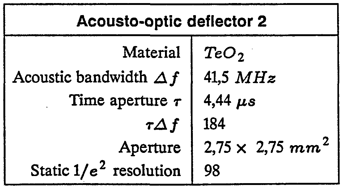


Figure 10 illustrates the positions of the subhologram groups (40) presented in Figure 5. The positions are relative to the symmetry axis (41) of the hologram (9). The distances are: l = 0,6 cm, l2 = 4,7 cm, 1 = 8,9 cm , Z = 13,0 cm, lζ = 17,1 cm .
In the system described above the number of the subholograms is 80. With one subhologram we can draw 128 image spots. The total number of image spots may then be 10240. Because the first and the last subholograms are used to check the deflection angles, the total number of spots which can be drawn is 9984. Hence all of the 9932 image spots can be drawn and in addition 52 points are in reserve.
The gratings and the holograms can be fabricated e.g. by electron beam etching. They can easily be copied by embossing or they can be made interfero- metrically. For the non-mechanical deflector elements we can use FbMoO^ crystal. In this case we have to build certain optics around these deflectors, or we can use a single crystal deflecting the light beam in both directions. Also, all of the subholograms need not be in the same plane. They can be on a curved surface so that in the case of reflection holograms, near the edges on the image line the subholograms may be closer to the image line. Hence, the distance from the grating to subholograms is the same for almost all of the subgratings, and in this case the optimization is also simpler. Checking the deflection angles can also be carried out at the edges of the subholograms. Hence we can draw the image line using only the center part of this kind of subhologram. Monitoring can also happen more than twice. The method is not restricted to the descibed construction only. The scanner may also be made such that the beam first hits the focusing hologram and then from the hologram the beam propagates to several separate gratings which direct the beam to the image line. In the system there can also be several holograms, and the combined effect of these holograms and the rest of optics will be the desired spots. The focusing of the beam can also be accomplished by separate lenses, the holograms being used only to direct the focused beam to the desired image spots. The acousto-optic deflectors can be tilted with respect to the direc¬ tion of the image line, the combined effect of these deflectors being the desired effect In the elimination of the errors in the vertical direction it is essential that we obtain a diverging cylindrical wave. The divergence point of this cylindrical wave does not depend on the vertical deflection angle. The method described above is only one way to obtain this effect. We could e.g. use a broader laser beam which is focused. In this case the distance between the focusing element and the sub- hologram is greater than the divergence radius of the cylindrical wave, and the focal length is not equal to their distance. The diverging cylindrical wave can also be made using diverging lenses.
Claims
1. A method for making an image line (10) with a laser beam, according to which
- the laser beam is created by a laser (1) - the intensity of the laser beam is modulated by an external modulator or by said laser (1)
- said modulated laser beam is fed into a coding element (2,3), by means of which at least one of the properties of the laser beam is transformed, e.g. amplitude, phase or direction, using an electrical control signal - the coded laser beam is fed into the hologram (9), by means of which the laser beam is transformed into focused image spots (20 ... 24a,b,c)
- from said image spots (20 ... 24a,b,c) an image line (10) is formed on the image plane and
- said laser beam is guided and transformed by optical elements characterized in that
- by means of said coding element" (2,3) the above mentioned characteristic of said laser beam is changed so that when changing the input signal to said coding element (2,3) a number of coded, in some sense orthogonal fields are created - said optics and said holograms (9) are designed together with the coding element so that with the aid of said hologram (9) the coded fields are sepa- ' rable so that each separate field forms one said image spot (20 ... 24a,b,c) on said image plane
- scanning the input signal of said coding element (2,3) across its values, a number of said image spots can be formed (20 ... 24a,b,c), which form said image line (10) and
- said coding element (2,3), said optics and said hologram (9) are so desig¬ ned that the position error of said image spots (20 ... 24a,b,c) can be diminished by means of electronic circuits.
2. A method as claimed in claim 1, wherein said laser beam coding element
(2,3) comprises of two non-mechanical laser beam deflectors, the deflection direc¬ tions of which are mutually perpendicular, and further comprising of the steps of transforming and directing said laser beam by lenses (4-7), and by at least one grating, mirror or prism (8), and wherein said image spots (20 ... 24a,b,c) are for¬ med by said holograms (9).
3. A method as claimed in claim 2, wherein said non-mechanical deflection to two mutually perpendicular directions is made by acousto-optic deflectors (2,3) or electro-optic deflectors.
4. A method as claimed in claim 2, wherein said coded laser beam is fed into said hologram (9), which is constituted of several subholograms (60, 17), which have a suitably optimized effect, and wherein by means of one single focusing subhologram (60, 17) more than one said image spot (20 ... 24a,b,c) is formed so that the different said image spots (20 ... 24a,b,c) formed by a single said focusing subhologram (60, 17) are obtained by changing the incoming angle of the beam in the direction of said image line (10).
5. A method as claimed in claim 2, comprising of the steps of scanning said deflection angle in the direction of said image line (10) continuously, and step- wise in the direction perpendicular to this.
6. A method as claimed in claim 4, comprising of the step of changing the direction of said laser beam using an element which includes several subele- ments, so designed that every subelement directs a beam which hits it at a certain value of a vertical deflection angle to a certain subhologram (60, 17), and the beam is caused to hit the different said subholograms (60, 17) by changing the vertical deflection angle, and as said subelement we use a grating, a mirror or a prism.
7. A method as claimed in claim 2, comprising the step of measuring said deflection angles of said non-mechanical deflectors at least once during the gene- ration of one said image line (10), and teh measurement is carried out by direc¬ ting the beam by means of certain subholograms (31, 32) or parts of subholo¬ grams to photodetectors (37, 38), with the aid of which the exact said deflection angle both in the direction of said image line (10) and the direction perpendicu¬ lar to it can be evaluated.
8. A method as claimed in claim 1, comprising the step of designing said coding element (2,3), said optics and said hologram (9) so that said image spot (20 ... 24a,b,c) is, in the direction perpendicular to said image line (10), an image, in this direction, of some non-moving part of the laser beam (13), whereby in this direction the error of the position of- said image spot (20 ... 24 a,b,c) becomes smaller.
9. A method as claimed in claims 6 and 8, wherein said optics is designed so that said laser beam which hits said subholograms (60, 17) is collimated in the direction of said image line (10), and wherein in the direction perpendicular to this it can be approximated by a diverging cylindrical wave, and the divergence point of said cylindrical wave, in the direction of the divergence, is approximately independent of said vertical deflection angle, whereby the error of said image spot (20 ... 24a,b,c) in the direction of divergence becomes smaller when said laser beam is focused.
Priority Applications (1)
| Application Number | Priority Date | Filing Date | Title |
|---|---|---|---|
| GB8702310A GB2188444B (en) | 1985-06-20 | 1986-06-19 | A method for scanning a laser beam by non-mechanical deflectors |
Applications Claiming Priority (2)
| Application Number | Priority Date | Filing Date | Title |
|---|---|---|---|
| FI852453 | 1985-06-20 | ||
| FI852453A FI74154C (en) | 1985-06-20 | 1985-06-20 | FOERFARANDE FOER BESTRYKNING AV LASERSTRAOLE MEDELST ICKE-MEKANISKA AVLAENKNINGSDON. |
Publications (1)
| Publication Number | Publication Date |
|---|---|
| WO1986007640A1 true WO1986007640A1 (en) | 1986-12-31 |
Family
ID=8521013
Family Applications (1)
| Application Number | Title | Priority Date | Filing Date |
|---|---|---|---|
| PCT/FI1986/000065 Ceased WO1986007640A1 (en) | 1985-06-20 | 1986-06-19 | A method for scanning a laser beam by non-mechanical deflectors |
Country Status (6)
| Country | Link |
|---|---|
| US (1) | US4925261A (en) |
| JP (1) | JPS63500897A (en) |
| DE (1) | DE3690327T1 (en) |
| FI (1) | FI74154C (en) |
| GB (1) | GB2188444B (en) |
| WO (1) | WO1986007640A1 (en) |
Cited By (4)
| Publication number | Priority date | Publication date | Assignee | Title |
|---|---|---|---|---|
| WO1989012369A1 (en) * | 1988-06-06 | 1989-12-14 | Spectrum Sciences B.V. | Multi-beam laser scanner system |
| US4938550A (en) * | 1987-02-03 | 1990-07-03 | Fujitsu Limited | Holographic deflection device |
| GB2231679A (en) * | 1989-04-07 | 1990-11-21 | Citizen Watch Co Ltd | Optical beam scanning system |
| WO1999004303A1 (en) * | 1997-07-16 | 1999-01-28 | The Lions Eye Institute Of Western Australia Incorporated | Laser scanning apparatus and method |
Families Citing this family (10)
| Publication number | Priority date | Publication date | Assignee | Title |
|---|---|---|---|---|
| US5097351A (en) * | 1990-08-06 | 1992-03-17 | Holotek, Ltd. | Simultaneous multibeam scanning system |
| DE4124203A1 (en) * | 1991-07-20 | 1993-01-21 | Krupp Ag | HOLOGRAPHIC TAGS |
| JPH05210141A (en) * | 1992-01-30 | 1993-08-20 | Matsushita Electric Ind Co Ltd | Optical information processing device |
| US5651600A (en) * | 1992-09-28 | 1997-07-29 | The Boeing Company | Method for controlling projection of optical layup template utilizing cooperative targets |
| JPH08328050A (en) * | 1995-05-29 | 1996-12-13 | Fuji Xerox Co Ltd | Optical scanning element, optical scanning method and image forming device using the same |
| US6480323B1 (en) | 1998-12-18 | 2002-11-12 | Carnegie Mellon University | Two-dimensional beam scanner |
| US6567206B1 (en) | 2001-12-20 | 2003-05-20 | St. Clair Intellectual Property Consultants, Inc. | Multi-stage optical switching device |
| US7177494B1 (en) | 2005-01-14 | 2007-02-13 | St. Clair Intellectual Property Consultants, Inc. | Optical control device and method |
| TWI523720B (en) | 2009-05-28 | 2016-03-01 | 伊雷克托科學工業股份有限公司 | Acousto-optic deflector applications in laser processing of features in a workpiece, and related laser processing method |
| CN118492645B (en) * | 2024-06-04 | 2024-12-27 | 珠海市申科谱工业科技有限公司 | Laser marking equipment and laser marking method |
Citations (3)
| Publication number | Priority date | Publication date | Assignee | Title |
|---|---|---|---|---|
| US3851951A (en) * | 1974-01-16 | 1974-12-03 | Isomet Corp | High resolution laser beam recorder with self-focusing acousto-optic scanner |
| US4106844A (en) * | 1975-06-25 | 1978-08-15 | Xerox Corporation | Laser scanning system utilizing computer generated holograms |
| US4307929A (en) * | 1979-08-29 | 1981-12-29 | Eveleth Jason H | Method of scanning a laser beam in a straight line |
Family Cites Families (3)
| Publication number | Priority date | Publication date | Assignee | Title |
|---|---|---|---|---|
| JPS562933B2 (en) * | 1974-09-04 | 1981-01-22 | ||
| US4547037A (en) * | 1980-10-16 | 1985-10-15 | Regents Of The University Of Minnesota | Holographic method for producing desired wavefront transformations |
| JPS59189312A (en) * | 1983-03-30 | 1984-10-26 | イ−ロ・ビツクリング | Method of obtaining high resolution laser beam deflector from low resolution part |
-
1985
- 1985-06-20 FI FI852453A patent/FI74154C/en not_active IP Right Cessation
-
1986
- 1986-06-19 US US07/027,205 patent/US4925261A/en not_active Expired - Fee Related
- 1986-06-19 JP JP61503581A patent/JPS63500897A/en active Pending
- 1986-06-19 WO PCT/FI1986/000065 patent/WO1986007640A1/en not_active Ceased
- 1986-06-19 DE DE19863690327 patent/DE3690327T1/de not_active Ceased
- 1986-06-19 GB GB8702310A patent/GB2188444B/en not_active Expired
Patent Citations (3)
| Publication number | Priority date | Publication date | Assignee | Title |
|---|---|---|---|---|
| US3851951A (en) * | 1974-01-16 | 1974-12-03 | Isomet Corp | High resolution laser beam recorder with self-focusing acousto-optic scanner |
| US4106844A (en) * | 1975-06-25 | 1978-08-15 | Xerox Corporation | Laser scanning system utilizing computer generated holograms |
| US4307929A (en) * | 1979-08-29 | 1981-12-29 | Eveleth Jason H | Method of scanning a laser beam in a straight line |
Cited By (5)
| Publication number | Priority date | Publication date | Assignee | Title |
|---|---|---|---|---|
| US4938550A (en) * | 1987-02-03 | 1990-07-03 | Fujitsu Limited | Holographic deflection device |
| WO1989012369A1 (en) * | 1988-06-06 | 1989-12-14 | Spectrum Sciences B.V. | Multi-beam laser scanner system |
| GB2231679A (en) * | 1989-04-07 | 1990-11-21 | Citizen Watch Co Ltd | Optical beam scanning system |
| GB2231679B (en) * | 1989-04-07 | 1993-09-15 | Citizen Watch Co Ltd | Optical beam scanning apparatus |
| WO1999004303A1 (en) * | 1997-07-16 | 1999-01-28 | The Lions Eye Institute Of Western Australia Incorporated | Laser scanning apparatus and method |
Also Published As
| Publication number | Publication date |
|---|---|
| GB2188444B (en) | 1989-07-26 |
| FI852453A0 (en) | 1985-06-20 |
| GB8702310D0 (en) | 1987-03-11 |
| FI852453L (en) | 1986-12-21 |
| JPS63500897A (en) | 1988-03-31 |
| FI74154C (en) | 1987-12-10 |
| GB2188444A (en) | 1987-09-30 |
| DE3690327T1 (en) | 1987-08-06 |
| FI74154B (en) | 1987-08-31 |
| US4925261A (en) | 1990-05-15 |
Similar Documents
| Publication | Publication Date | Title |
|---|---|---|
| WO1986007640A1 (en) | A method for scanning a laser beam by non-mechanical deflectors | |
| US4094576A (en) | Straight-line optical scanner using rotating holograms | |
| US6384949B1 (en) | Optical scanning device, image forming apparatus and optical scanning method | |
| EP0300571B1 (en) | Scanning optical microscope | |
| US4946234A (en) | Light beam deflection scanning method and an apparatus therefor | |
| AU7234287A (en) | Scanning apparatus | |
| US3922059A (en) | Method of converting circular scanning lines into linear scanning lines | |
| EP0288970B1 (en) | Optical system for flyingspot scanning system | |
| GB2248119A (en) | Two mirror scanner with pincushion error correction | |
| US5013108A (en) | Optical scanning device and mirror correction system for use in such a device | |
| US4559445A (en) | Wide angle optical transmitter/receiver | |
| US6771421B2 (en) | Beam pattern contractor and focus element, method and apparatus | |
| EP0663606A2 (en) | Laser beam scanning radiating apparatus | |
| US3485546A (en) | Field flattener scanning means | |
| US4776654A (en) | Scanning optical system | |
| US3669522A (en) | Reflective relay optical system for two-axis deflection | |
| US5870227A (en) | Scanning head lens assembly | |
| EP0277883B1 (en) | Holographic deflection device | |
| US4398787A (en) | Optical leverage telecentric scanning apparatus | |
| EP0078269A1 (en) | Improved diffraction grating scanner with anamorphic correction of scan curvatures | |
| JP3574640B2 (en) | Optical correlator and optical correlation method for adaptive matching | |
| JPH04123016A (en) | Phase shift element and laser device using the same | |
| US3464760A (en) | Optical system with variable focal length | |
| US4158486A (en) | Light beam message character generating system | |
| Beiser | Resolution of laser scanners |
Legal Events
| Date | Code | Title | Description |
|---|---|---|---|
| AK | Designated states |
Kind code of ref document: A1 Designated state(s): DE GB JP SE US |
|
| RET | De translation (de og part 6b) |
Ref document number: 3690327 Country of ref document: DE Date of ref document: 19870806 |
|
| WWE | Wipo information: entry into national phase |
Ref document number: 3690327 Country of ref document: DE |