USRE35123E - Vehicle body mount - Google Patents
Vehicle body mount Download PDFInfo
- Publication number
- USRE35123E USRE35123E US08/370,260 US37026095A USRE35123E US RE35123 E USRE35123 E US RE35123E US 37026095 A US37026095 A US 37026095A US RE35123 E USRE35123 E US RE35123E
- Authority
- US
- United States
- Prior art keywords
- tubular portion
- spacer member
- clip
- central aperture
- noncircular
- Prior art date
- Legal status (The legal status is an assumption and is not a legal conclusion. Google has not performed a legal analysis and makes no representation as to the accuracy of the status listed.)
- Expired - Lifetime
Links
- 125000006850 spacer group Chemical group 0.000 claims abstract description 104
- 239000002184 metal Substances 0.000 claims abstract description 16
- 230000002093 peripheral effect Effects 0.000 claims 12
- 230000037431 insertion Effects 0.000 claims 6
- 238000003780 insertion Methods 0.000 claims 6
- 239000011248 coating agent Substances 0.000 claims 1
- 238000000576 coating method Methods 0.000 claims 1
- 230000002452 interceptive effect Effects 0.000 description 2
- 238000012423 maintenance Methods 0.000 description 2
- CWYNVVGOOAEACU-UHFFFAOYSA-N Fe2+ Chemical compound [Fe+2] CWYNVVGOOAEACU-UHFFFAOYSA-N 0.000 description 1
- 230000000712 assembly Effects 0.000 description 1
- 238000000429 assembly Methods 0.000 description 1
- 239000011324 bead Substances 0.000 description 1
- JXSJBGJIGXNWCI-UHFFFAOYSA-N diethyl 2-[(dimethoxyphosphorothioyl)thio]succinate Chemical compound CCOC(=O)CC(SP(=S)(OC)OC)C(=O)OCC JXSJBGJIGXNWCI-UHFFFAOYSA-N 0.000 description 1
- 230000008030 elimination Effects 0.000 description 1
- 238000003379 elimination reaction Methods 0.000 description 1
- 239000000463 material Substances 0.000 description 1
- 238000000034 method Methods 0.000 description 1
Images


Classifications
-
- B—PERFORMING OPERATIONS; TRANSPORTING
- B60—VEHICLES IN GENERAL
- B60G—VEHICLE SUSPENSION ARRANGEMENTS
- B60G99/00—Subject matter not provided for in other groups of this subclass
- B60G99/004—Other suspension arrangements with rubber springs
-
- B—PERFORMING OPERATIONS; TRANSPORTING
- B62—LAND VEHICLES FOR TRAVELLING OTHERWISE THAN ON RAILS
- B62D—MOTOR VEHICLES; TRAILERS
- B62D27/00—Connections between superstructure or understructure sub-units
- B62D27/04—Connections between superstructure or understructure sub-units resilient
-
- F—MECHANICAL ENGINEERING; LIGHTING; HEATING; WEAPONS; BLASTING
- F16—ENGINEERING ELEMENTS AND UNITS; GENERAL MEASURES FOR PRODUCING AND MAINTAINING EFFECTIVE FUNCTIONING OF MACHINES OR INSTALLATIONS; THERMAL INSULATION IN GENERAL
- F16B—DEVICES FOR FASTENING OR SECURING CONSTRUCTIONAL ELEMENTS OR MACHINE PARTS TOGETHER, e.g. NAILS, BOLTS, CIRCLIPS, CLAMPS, CLIPS OR WEDGES; JOINTS OR JOINTING
- F16B5/00—Joining sheets or plates, e.g. panels, to one another or to strips or bars parallel to them
- F16B5/02—Joining sheets or plates, e.g. panels, to one another or to strips or bars parallel to them by means of fastening members using screw-thread
- F16B5/0258—Joining sheets or plates, e.g. panels, to one another or to strips or bars parallel to them by means of fastening members using screw-thread using resiliently deformable sleeves, grommets or inserts
-
- F—MECHANICAL ENGINEERING; LIGHTING; HEATING; WEAPONS; BLASTING
- F16—ENGINEERING ELEMENTS AND UNITS; GENERAL MEASURES FOR PRODUCING AND MAINTAINING EFFECTIVE FUNCTIONING OF MACHINES OR INSTALLATIONS; THERMAL INSULATION IN GENERAL
- F16F—SPRINGS; SHOCK-ABSORBERS; MEANS FOR DAMPING VIBRATION
- F16F1/00—Springs
- F16F1/36—Springs made of rubber or other material having high internal friction, e.g. thermoplastic elastomers
- F16F1/42—Springs made of rubber or other material having high internal friction, e.g. thermoplastic elastomers characterised by the mode of stressing
- F16F1/44—Springs made of rubber or other material having high internal friction, e.g. thermoplastic elastomers characterised by the mode of stressing loaded mainly in compression
-
- F—MECHANICAL ENGINEERING; LIGHTING; HEATING; WEAPONS; BLASTING
- F16—ENGINEERING ELEMENTS AND UNITS; GENERAL MEASURES FOR PRODUCING AND MAINTAINING EFFECTIVE FUNCTIONING OF MACHINES OR INSTALLATIONS; THERMAL INSULATION IN GENERAL
- F16F—SPRINGS; SHOCK-ABSORBERS; MEANS FOR DAMPING VIBRATION
- F16F3/00—Spring units consisting of several springs, e.g. for obtaining a desired spring characteristic
- F16F3/08—Spring units consisting of several springs, e.g. for obtaining a desired spring characteristic with springs made of a material having high internal friction, e.g. rubber
- F16F3/087—Units comprising several springs made of plastics or the like material
- F16F3/0873—Units comprising several springs made of plastics or the like material of the same material or the material not being specified
-
- B—PERFORMING OPERATIONS; TRANSPORTING
- B60—VEHICLES IN GENERAL
- B60G—VEHICLE SUSPENSION ARRANGEMENTS
- B60G2204/00—Indexing codes related to suspensions per se or to auxiliary parts
- B60G2204/10—Mounting of suspension elements
- B60G2204/16—Mounting of vehicle body on chassis
-
- B—PERFORMING OPERATIONS; TRANSPORTING
- B60—VEHICLES IN GENERAL
- B60G—VEHICLE SUSPENSION ARRANGEMENTS
- B60G2204/00—Indexing codes related to suspensions per se or to auxiliary parts
- B60G2204/40—Auxiliary suspension parts; Adjustment of suspensions
- B60G2204/41—Elastic mounts, e.g. bushings
-
- B—PERFORMING OPERATIONS; TRANSPORTING
- B60—VEHICLES IN GENERAL
- B60G—VEHICLE SUSPENSION ARRANGEMENTS
- B60G2204/00—Indexing codes related to suspensions per se or to auxiliary parts
- B60G2204/40—Auxiliary suspension parts; Adjustment of suspensions
- B60G2204/44—Centering or positioning means
-
- F—MECHANICAL ENGINEERING; LIGHTING; HEATING; WEAPONS; BLASTING
- F16—ENGINEERING ELEMENTS AND UNITS; GENERAL MEASURES FOR PRODUCING AND MAINTAINING EFFECTIVE FUNCTIONING OF MACHINES OR INSTALLATIONS; THERMAL INSULATION IN GENERAL
- F16F—SPRINGS; SHOCK-ABSORBERS; MEANS FOR DAMPING VIBRATION
- F16F2236/00—Mode of stressing of basic spring or damper elements or devices incorporating such elements
- F16F2236/04—Compression
-
- Y—GENERAL TAGGING OF NEW TECHNOLOGICAL DEVELOPMENTS; GENERAL TAGGING OF CROSS-SECTIONAL TECHNOLOGIES SPANNING OVER SEVERAL SECTIONS OF THE IPC; TECHNICAL SUBJECTS COVERED BY FORMER USPC CROSS-REFERENCE ART COLLECTIONS [XRACs] AND DIGESTS
- Y10—TECHNICAL SUBJECTS COVERED BY FORMER USPC
- Y10T—TECHNICAL SUBJECTS COVERED BY FORMER US CLASSIFICATION
- Y10T403/00—Joints and connections
- Y10T403/45—Flexibly connected rigid members
- Y10T403/454—Connecting pin traverses radially interposed elastomer
Definitions
- This invention relates to means for mounting a vehicle body on a vehicle frame.
- Vehicle bodies are commonly mounted on vehicle frames by the use of a body mount including a pair of uper and lower resilient blocks and a pair of upper and lower sheet metal spacer members each having a generally planar flange portion and an integral elongate tubular portion.
- the resilient blocks are positioned on upper and lower sides of the vehicle frame in alignment with and opening in the frame, the tubular portions of the sheet metal spacer members are respectively inserted in a central opening in a respective resilient block, and the inboard ends of tubular portions are secured together to respectively secure the resilient blocks to upper and lower sides of the vehicle frame.
- a vehicle body mount of this general type is disclosed in U.S. Pat. No. 3,809,427 to Bennett.
- Bennett the tubular portion of the upper spacer member is provided with a reduced diameter section nearest the lower free end of the tubular portion and the tubular portion of the lower spacer member is of a small enough diameter to be telescopically received within the reduced diameter lower section of the tubular portion of the upper spacer member.
- a special staking gun is required to provide a compressive force upon the spacer members and the resilient blocks and cause the free end of the tubular portion of the lower spacer member to flair outwardly into locking engagement with the shoulder created by the changing diameter of the tubular portion of the upper spacer member.
- this body mount structure has proven to be generally satisfactory, it requires the use of a special staking gun to accomplish the mounting operation, and this gun adds significantly to the cost of the assembly operation since the gun represents an item of capital investment, represents repair and maintenance expense, and consumes precious and expensive space along the assembly line.
- This invention is directed to the provision of a vehicle body mount assembly that allows the body mount to be assembled in a production line environment with a minimum of unskilled effort and without the aid of any special tools.
- the vehicle body mount assembly includes an upper sheet metal spacer member, a lower sheet metal spacer member, and a sheet metal clip member.
- the upper sheet metal spacer includes a flange portion having a central aperture and a tubular portion extending downwardly from the flange portion in coaxial relation to the central aperture and having radially inwardly extending lip means adjacent the lower end thereof.
- the lower sheet metal spacer member includes a flange portion having a central aperture and a tubular portion extending upwardly from the flange portion in coaxial relation to the central aperture and size to be received telescopically within the tubular portion of the upper spacer member.
- the metal clip member is generally circular and is sized to fit over and encircle the upper end of the tubular portion of the lower spacer member and includes catch means projecting radially outwardly therefrom for snapping coaction with the lip means on the tubular portion of the upper spacer member in response to relative axial, telescopic movement of the upper end of the tubular portion of the lower spacer member into the lower end of the tubular portion of the upper spacer member.
- This arrangement provides an inexpensive and effective means of securing the resilient blocks to the upper and lower sides of the vehicle frame without the use of any special tools.
- the clip member is split to facilitate placement over the upper end of the tubular portion of the lower spacer member.
- the lower spacer member tubular portion includes diametrically opposed flat side portions adjacent the upper end thereof and the clip member includes diametrically opposed flat side portions sized to seat on the flat side portions of the lower spacer member tubular portion to preclude rotation of the clip member on the lower spacer member tubular portion.
- the extreme upper end of the lower spacer member tubular portion is flared outwardly above the flat side portions thereof to preclude upward movement of the clip member on the lower spacer member tubular portion and a radially outwardly extending shoulder provided on the lower spacer member tubular portion immediately below the flat side portions thereof to preclude downward movement of the clip member on the lower spacer member tubular portion.
- the lower spacer member further includes a nut member rigidly secured to the underface of the flange portion thereof in coaxial relation to the central aperture in the flange portion.
- This nut member in the final assembly operation of the vehicle body to the vehicle frame using the invention vehicle mount assembly, threadably receives the lower end of a bolt passed downwardly through a hole in the vehicle body and through the aligned tubular portions of the upper and lower spacer members.
- the upper spacer member tubular portion includes two diametrically opposed arcuate side portions interconnected by two diametrically opposed flat side portions, corresponding to the flat side portions of the lower spacer member tubular portion and of the clip member, and the lip means comprise arcuate lips provided within the arcuate side portions adjacent the lower end of the upper spacer member tubular portion.
- the flat side portions of the lower spacer member tubular portion are interconnected by two diametrically opposed arcuate side portions; the flat side portions of the clip member are interconnected by diametrically opposed arcuate side portions sized and configured to seat over the arcuate side portions of the lower spacer member tubular portion; and the catch means comprises outwardly projecting and downwardly extending prong portions struck from the arcuate side portions of the clip member.
- the split in the clip member is provided in one of the arcuate side portions thereof.
- the lower spacer member is rotated relative to the upper spacer member to bring the arcuate and flat side portions of the clip member into respective interferring engagement with the flat and arcuate side portions of the upper spacer member tubular portion and thereby augment the locking interengagement between the upper and lower spacer members.
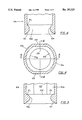
- FIG. 1 is an exploded perspective view of the components of the vehicle body mount assembly of the invention
- FIG. 2 is a cross-sectional view showing the invention vehicle body mount assembly as utilized in the mounting of a vehicle body to a vehicle frame;
- FIG. 3 is a detailed view of the area within the circle 3 of FIG. 2;
- FIG. 4 is a cross-sectional view taken on line 4--4 of FIG. 1;
- FIGS. 5 and 6 are fragmentary cross-sectional views taken respectively on lines 5--5 and 6--6 of FIG. 4.
- the invention vehicle body mount assembly broadly considered comprises an upper sheet metal spacer member 10, a lower sheet metal spacer member 12, and a clip member 14.
- Members 10, 12 and 14 may be formed in stamping operations from suitable ferrous material.
- Upper spacer member 10 includes a circular flange portion 10a, having a central aperture 10b, and a tubular portion 10c extending downwardly from flange portion 10a in coaxial relation to aperture 10b. Radially inwardly extending lip means 10d is provided adjacent the lower end of tubular portion 10c.
- Tubular portion 10c includes two diametrically opposed arcuate side portions 10e interconnected by two diametrically opposed flat side portions 10f.
- Lip means 10d is provided around the inner circumference of the lower end of tubular portion 10c and includes relatively thick lip portions 10g extending around the inner circumference of arcuate side portions 10e and relatively thin lip portions portions 10h adjacent the inner circumference of flat side portions 10f.
- a circumferential bevel face 10i interconnects lip means 10d with the extreme lower end of the tubular portion 10c.
- Lower spacer member 12 includes a circular flange portion 12a, having a central aperture 12b, and a tubular portion 12c extending upwardly from flange portion 12a in coaxial relation to central aperture 12b and generally sized to be received telescopically within the lower end of the tubular portion 10c of the upper spacer member 10.
- Upstanding tubular portion 12c includes a base portion 12e, an attachment portion 12f, and a flared portion 12g.
- Base portion 12e includes diametrically opposed flat side portions 12h interconnected by diametrically opposed arcuate side portions 12i.
- Attachment portion 12f includes diametrically opposed flat side portions 12j interconnected by diametrically opposed arcuate portions 12k.
- Attachment portion 12f is of reduced diametric dimensions relative to base portion 12e and forms an annular shoulder 121 at its juncture with base portion 12e.
- Flare portion 12g is provided at the extreme upper end of tubular portion 12c and flares outwardly relative to attachment portion 12f.
- Flare portion 12g like base portion 12e and attachment portion 12f, includes diametrically opposed flat side portions interconnected by diametrically opposed arcuate side portions so as to form a complete, outwardly flaring, conforming lip all the way around the upper end of attachment portion 12f.
- Clip member 14 comprises a split ring and includes diametrically opposed flat side portions 14a interconnected by diametrically opposed arcuate side portions 14b.
- the split in the ring is provided at 14c in one of the arcuate side portions 14b.
- a pair of angularly spaced prongs 14d are struck from each arcuate side portion 14b and extend outwardly and downwardly with respect to the main body of the clip member.
- the invention vehicle body mount assembly is used in cooperation with a pair of resilient, upper and lower elastomeric blocks 16, 18 and a bolt 20 to secure a vehicle body 22 to a vehicle frame 24.
- the tubular portion of the upper spacer member is passed downwardly through the central aperture in upper elastomeric block 16;
- the upper block and spacer member subassembly is positioned on the upper face of frame 24 with the lower end of tubular portion 10c passing downwardly through an aperture 24a in the frame;
- clip member 14 is seated on the attachment portion 12f of lower spacer member 12 by expanding the clip so as to enable it to pass over flare portion 12g for seating on attachment portion 12f
- lower resilient block 18 is assembled to spacer member 12 and clip member 14 by passing the tubular portion 12c of the lower spacer member, with the clip member attached, upwardly into the central aperture of the lower block; and the lower block, lower spacer member, and clip member subassembly is moved upwardly to position the upper face of the lower block 18
- lip means 10d passes downwardly past the projecting prong portions 14d to squeeze the prong portions inwardly whereafter, once the lip means has cleared the prong portions, the prong portions spring outwardly to lockingly and snappingly engage with the upper annular shoulder 10j of the lip means to preclude downward movement of the lower spacer member relative to the upper spacer member.
- lower spacer member 12 and clip member 14 may thereafter be rotated through approximately 90° relative to the upper spacer member to bring the flat side portions of the clip member into interfering engagement with the arcuate portions of the tubular portion of the upper spacer member and to bring the arcuate side portions of the clip member into interfering engagement with the flat side portions of the tubular portion of the upper spacer member to further lock the lower spacer member with respect to the upper spacer member.
- the body 22 of the vehicle is positioned on the upper face of the upper flange portion of the upper spacer member and bolt 20 is passed downwardly through an aperture 22a in the body and through aligned tubular portions 10c, 12c for engagement with a nut 26 welded to the underface of flange portion 12a of lower spacer member 12 in coaxial relation to aperture 12b.
- the invention vehicle body mount assembly will be seen to provide an inexpensive and effective means of quickly mounting a vehicle body to a vehicle frame without the use of skilled labor and without utilization of any special tools. Elimination of the special tools required with previous vehicle mount assemblies eliminates the capital investment with respect to such tools, eliminates the maintenance and repair with respect to such tools, and frees up valuable and expensive space along the assembly line for other purposes.
Landscapes
- Engineering & Computer Science (AREA)
- General Engineering & Computer Science (AREA)
- Mechanical Engineering (AREA)
- Chemical & Material Sciences (AREA)
- Combustion & Propulsion (AREA)
- Transportation (AREA)
- Health & Medical Sciences (AREA)
- Child & Adolescent Psychology (AREA)
- Connection Of Plates (AREA)
Abstract
A vehicle body mount assembly comprising an upper sheet metal spacer member, a lower sheet metal spacer member, and a sheet metal clip member. The upper sheet metal spacer member includes a flange portion having a central aperture and a tubular portion extending downwardly from the flange portion in coaxial relation to the central aperture and including a radially inwardly extending lip adjacent the lower end thereof. The lower spacer member includes a flange portion having a central aperture and a tubular portion extending upwardly from the flange portion in coaxial relation to the central aperture thereof and sized to be received telescopically within the upper spacer member tubular portion. The clip member is split and is sized to fit snappingly over and encircle a reduced diameter annular seat defined on the upper end of the lower spacer member tubular portion and includes prongs struck radially outwardly therefrom for snapping coaction with the lip on the upper spacer member tubular portion in response to relative axial telescoping movement of the upper end of the lower spacer member tubular portion into the lower end of the upper spacer member tubular portion.
Description
This invention relates to means for mounting a vehicle body on a vehicle frame.
Vehicle bodies are commonly mounted on vehicle frames by the use of a body mount including a pair of uper and lower resilient blocks and a pair of upper and lower sheet metal spacer members each having a generally planar flange portion and an integral elongate tubular portion. The resilient blocks are positioned on upper and lower sides of the vehicle frame in alignment with and opening in the frame, the tubular portions of the sheet metal spacer members are respectively inserted in a central opening in a respective resilient block, and the inboard ends of tubular portions are secured together to respectively secure the resilient blocks to upper and lower sides of the vehicle frame.
A vehicle body mount of this general type is disclosed in U.S. Pat. No. 3,809,427 to Bennett. In Bennett, the tubular portion of the upper spacer member is provided with a reduced diameter section nearest the lower free end of the tubular portion and the tubular portion of the lower spacer member is of a small enough diameter to be telescopically received within the reduced diameter lower section of the tubular portion of the upper spacer member. During assembly, a special staking gun is required to provide a compressive force upon the spacer members and the resilient blocks and cause the free end of the tubular portion of the lower spacer member to flair outwardly into locking engagement with the shoulder created by the changing diameter of the tubular portion of the upper spacer member. Whereas this body mount structure has proven to be generally satisfactory, it requires the use of a special staking gun to accomplish the mounting operation, and this gun adds significantly to the cost of the assembly operation since the gun represents an item of capital investment, represents repair and maintenance expense, and consumes precious and expensive space along the assembly line.
This invention is directed to the provision of a vehicle body mount assembly that allows the body mount to be assembled in a production line environment with a minimum of unskilled effort and without the aid of any special tools.
The vehicle body mount assembly according to the invention includes an upper sheet metal spacer member, a lower sheet metal spacer member, and a sheet metal clip member. The upper sheet metal spacer includes a flange portion having a central aperture and a tubular portion extending downwardly from the flange portion in coaxial relation to the central aperture and having radially inwardly extending lip means adjacent the lower end thereof. The lower sheet metal spacer member includes a flange portion having a central aperture and a tubular portion extending upwardly from the flange portion in coaxial relation to the central aperture and size to be received telescopically within the tubular portion of the upper spacer member. The metal clip member is generally circular and is sized to fit over and encircle the upper end of the tubular portion of the lower spacer member and includes catch means projecting radially outwardly therefrom for snapping coaction with the lip means on the tubular portion of the upper spacer member in response to relative axial, telescopic movement of the upper end of the tubular portion of the lower spacer member into the lower end of the tubular portion of the upper spacer member. This arrangement provides an inexpensive and effective means of securing the resilient blocks to the upper and lower sides of the vehicle frame without the use of any special tools.
According to a further feature of the invention, the clip member is split to facilitate placement over the upper end of the tubular portion of the lower spacer member.
According to a further feature of the invention, the lower spacer member tubular portion includes diametrically opposed flat side portions adjacent the upper end thereof and the clip member includes diametrically opposed flat side portions sized to seat on the flat side portions of the lower spacer member tubular portion to preclude rotation of the clip member on the lower spacer member tubular portion.
According to a further feature of the invention, the extreme upper end of the lower spacer member tubular portion is flared outwardly above the flat side portions thereof to preclude upward movement of the clip member on the lower spacer member tubular portion and a radially outwardly extending shoulder provided on the lower spacer member tubular portion immediately below the flat side portions thereof to preclude downward movement of the clip member on the lower spacer member tubular portion.
According to a further feature of the invention, the lower spacer member further includes a nut member rigidly secured to the underface of the flange portion thereof in coaxial relation to the central aperture in the flange portion. This nut member, in the final assembly operation of the vehicle body to the vehicle frame using the invention vehicle mount assembly, threadably receives the lower end of a bolt passed downwardly through a hole in the vehicle body and through the aligned tubular portions of the upper and lower spacer members.
According to a further feature of the invention, the upper spacer member tubular portion includes two diametrically opposed arcuate side portions interconnected by two diametrically opposed flat side portions, corresponding to the flat side portions of the lower spacer member tubular portion and of the clip member, and the lip means comprise arcuate lips provided within the arcuate side portions adjacent the lower end of the upper spacer member tubular portion. This arrangement allows the respective flat side portions of the various members to be juxtaposed in the assembled configuration of the parts and facilitates the engagement of the lip means with the catch means on the lower spacer member.
According to a further feature of the invention, the flat side portions of the lower spacer member tubular portion are interconnected by two diametrically opposed arcuate side portions; the flat side portions of the clip member are interconnected by diametrically opposed arcuate side portions sized and configured to seat over the arcuate side portions of the lower spacer member tubular portion; and the catch means comprises outwardly projecting and downwardly extending prong portions struck from the arcuate side portions of the clip member.
According to a further feature of the invention, the split in the clip member is provided in one of the arcuate side portions thereof.
According to a further feature of the invention, after the upper and lower spacer members have been snappingly secured together, the lower spacer member is rotated relative to the upper spacer member to bring the arcuate and flat side portions of the clip member into respective interferring engagement with the flat and arcuate side portions of the upper spacer member tubular portion and thereby augment the locking interengagement between the upper and lower spacer members.
FIG. 1 is an exploded perspective view of the components of the vehicle body mount assembly of the invention;
FIG. 2 is a cross-sectional view showing the invention vehicle body mount assembly as utilized in the mounting of a vehicle body to a vehicle frame;
FIG. 3 is a detailed view of the area within the circle 3 of FIG. 2;
FIG. 4 is a cross-sectional view taken on line 4--4 of FIG. 1; and
FIGS. 5 and 6 are fragmentary cross-sectional views taken respectively on lines 5--5 and 6--6 of FIG. 4.
The invention vehicle body mount assembly broadly considered comprises an upper sheet metal spacer member 10, a lower sheet metal spacer member 12, and a clip member 14. Members 10, 12 and 14 may be formed in stamping operations from suitable ferrous material.
Upstanding tubular portion 12c includes a base portion 12e, an attachment portion 12f, and a flared portion 12g. Base portion 12e includes diametrically opposed flat side portions 12h interconnected by diametrically opposed arcuate side portions 12i. Attachment portion 12f includes diametrically opposed flat side portions 12j interconnected by diametrically opposed arcuate portions 12k. Attachment portion 12f is of reduced diametric dimensions relative to base portion 12e and forms an annular shoulder 121 at its juncture with base portion 12e. Flare portion 12g is provided at the extreme upper end of tubular portion 12c and flares outwardly relative to attachment portion 12f. Flare portion 12g, like base portion 12e and attachment portion 12f, includes diametrically opposed flat side portions interconnected by diametrically opposed arcuate side portions so as to form a complete, outwardly flaring, conforming lip all the way around the upper end of attachment portion 12f.
The invention vehicle body mount assembly is used in cooperation with a pair of resilient, upper and lower elastomeric blocks 16, 18 and a bolt 20 to secure a vehicle body 22 to a vehicle frame 24. In the process of mounting the vehicle body to the vehicle frame, the tubular portion of the upper spacer member is passed downwardly through the central aperture in upper elastomeric block 16; the upper block and spacer member subassembly is positioned on the upper face of frame 24 with the lower end of tubular portion 10c passing downwardly through an aperture 24a in the frame; clip member 14 is seated on the attachment portion 12f of lower spacer member 12 by expanding the clip so as to enable it to pass over flare portion 12g for seating on attachment portion 12f, lower resilient block 18 is assembled to spacer member 12 and clip member 14 by passing the tubular portion 12c of the lower spacer member, with the clip member attached, upwardly into the central aperture of the lower block; and the lower block, lower spacer member, and clip member subassembly is moved upwardly to position the upper face of the lower block 18 against the underface of frame 24 and to move the upper end of tubular portion 12c, with the clip member attached, upwardly into the lower end of tubular portion 10c of the upper spacer member.
As the clip member 14 is moved upwardly within the lower end of tubular portion 10c of the upper spacer member, lip means 10d passes downwardly past the projecting prong portions 14d to squeeze the prong portions inwardly whereafter, once the lip means has cleared the prong portions, the prong portions spring outwardly to lockingly and snappingly engage with the upper annular shoulder 10j of the lip means to preclude downward movement of the lower spacer member relative to the upper spacer member.
During the upward movement of the tubular portion of the lower spacer member, together with the clip member, into the lower end of the tubular portion of the upper spacer member, flats 10f on tubular portion 10c are angularly aligned with flats 14a on the clip member and flats 12j on the tubular portion of the lower spacer member to allow the upper tubular member to clear the flare portion 12g of the lower tubular member and so that relatively thick lip portions 10g of the lip means coact with prong portions 14d as the lip means lockingly engage the prong portions. If desired, lower spacer member 12 and clip member 14 may thereafter be rotated through approximately 90° relative to the upper spacer member to bring the flat side portions of the clip member into interfering engagement with the arcuate portions of the tubular portion of the upper spacer member and to bring the arcuate side portions of the clip member into interfering engagement with the flat side portions of the tubular portion of the upper spacer member to further lock the lower spacer member with respect to the upper spacer member.
At a further point along the assembly line, the body 22 of the vehicle is positioned on the upper face of the upper flange portion of the upper spacer member and bolt 20 is passed downwardly through an aperture 22a in the body and through aligned tubular portions 10c, 12c for engagement with a nut 26 welded to the underface of flange portion 12a of lower spacer member 12 in coaxial relation to aperture 12b.
The invention vehicle body mount assembly will be seen to provide an inexpensive and effective means of quickly mounting a vehicle body to a vehicle frame without the use of skilled labor and without utilization of any special tools. Elimination of the special tools required with previous vehicle mount assemblies eliminates the capital investment with respect to such tools, eliminates the maintenance and repair with respect to such tools, and frees up valuable and expensive space along the assembly line for other purposes.
Whereas the preferred embodiment of the invention has been illustrated and described in detail it will be apparent that various changes can be made in the disclosed embodiment without departing from the scope or spirit of the invention.
Claims (4)
1. A vehicle body mount assembly for attaching a vehicle to a vehicle frame by the use of a pair of resilient blocks, said assembly comprising:
A) an upper sheet metal spacer member including
(1) a flange portion having a central aperture, and
(2) a tubular portion extending downwardly from said flange portion in coaxial relation to said central aperture and having a noncircular interior periphery surface;
B) a lower sheet metal spacer member including
(1) a flange portion having a central aperture, and
(2) a tubular portion extending upwardly from said flange portion in coaxial relation to the central aperture thereof and sized to be received telescopically within said upper spacer member tubular portion;
C) a clip member fitting over said tubular portion of said lower spacer member and defining a noncircular exterior peripheral surface at its exterior peripheral surface generally corresponding in size and configuration to said noncircular interior surface;
D) means operative in response to telescoping axial insertion of said lower member tubular portion into said upper member tubular portion, within said noncircular surfaces aligned, to secure said upper member to said lower member, said operative means including
(1) a radially inwardly extending lip on said upper member tubular portion adjacent the lower end thereof; and
(2) prongs projecting radially outwardly from said clip member for snapping coaction with said lip in response to axial insertion of said lower member tubular portion into said upper member tubular portion;
E) said noncircular exterior peripheral surface of said clip coating with said noncircular interior surface of said tubular portion of said upper spacer member in the assembled relation of the body mount assembly to preclude relative rotation of said upper and lower spacer members;
F) said prongs lockingly engaging said lip in the assembled relation of the body mount assembly to preclude relative axial movement of said upper and lower spacer members;
G) said lower spacer member tubular portion defining a first radially outwardly extending shoulder proximate its upper end and a second radially outwardly extending shoulder at a location spaced below said first shoulder and coacting with said first shoulder to define an annular external seat therebetween;
H) said clip being positioned on said annular external seat with said shoulder coacting to preclude axial movement of said clip on said lower spacer member tubular portion.
2. The vehicle body mount assembly of claim 1 wherein said lower spacer member includes a nut member rigidly secured to the underface of said flange portion thereof in coaxial relation to said central aperture of said flange portion to receive a bolt passing axially through said upper and lower spacer members. .Iadd.
3. A vehicle body mount assembly for attaching a vehicle to a vehicle frame by the use of a pair of resilient blocks, said assembly comprising:
A) an upper spacer member including
(1) a flange portion having a central aperture, and
(2) a tubular portion extending downwardly from said flange portion in coaxial relation to said central aperture and having a noncircular interior peripheral surface;
B) a lower spacer member including
(1) a flange portion having a central aperture, and
(2) a tubular portion extending upwardly from said flange portion to an upper end in coaxial relation to the central aperture thereof and sized to be received telescopically within said upper spacer member tubular portion;
C) a clip member fitting over said tubular portion of said lower spacer member and defining a noncircular exterior peripheral surface at its exterior peripheral surface generally corresponding in size and configuration to said noncircular interior surface;
D) means operative response to telescoping axial insertion of said lower member tubular portion into said upper member tubular portion, with said noncircular surfaces aligned, to secure said upper member to said lower member, said operative means including
(1) a radially inwardly extending shoulder on said upper member tubular portion; and
(2) prongs projecting radially outwardly from said clip member for snapping coaction with said radially inwardly extending shoulder in response to axial insertion of said lower member tubular portion into said upper member tubular portion;
E) said noncircular exterior peripheral surface of said clip coacting with said noncircular interior surface of said tubular portion of said upper spacer member in the assembled relation of the body mount assembly to preclude relative rotation of said upper and lower spacer members;
F) said prongs lockingly engaging said radially inwardly extending shoulder in the assembled relation of the body mount assembly to preclude relative axial movement of said upper and lower spacer members;
G) said lower spacer member tubular portion defining an annular seat;
H) said clip being positioned on said annular seat with means precluding axial movement of said clip on said lower spacer member tubular portion. .Iaddend. .Iadd.
4. The vehicle body mount assembly of claim 3 wherein the means precluding axial movement of said clip on said lower spacer member tubular portion includes a radially outwardly extending shoulder on said tubular portion spaced below said upper end. .Iaddend. .Iadd.5. The vehicle body mount assembly of claim 4 wherein said annular seat is on an external peripheral surface of the tubular portion of said lower spacer member. .Iaddend. .Iadd.6. A vehicle body mount assembly for attaching a vehicle to a vehicle frame by the use of a pair of resilient blocks, said assembly comprising:
A) an upper spacer member including
(1) a flange portion having a central aperture, and
(2) a tubular portion extending downwardly from said flange portion in coaxial relation to said central aperture and having a noncircular interior peripheral surface;
B) a lower spacer member including
(1) a flange portion having a central aperture, and
(2) a tubular portion extending upwardly from said flange portion to an upper end in coaxial relation to the central aperture thereof and sized to be received telescopically within said upper spacer member tubular portion;
C) a clip member fitting over said tubular portion of said lower spacer member and defining a noncircular exterior peripheral surface at its exterior peripheral surface generally corresponding in size and configuration to said noncircular interior surface;
D) means operative in response to telescoping axial insertion of said lower member tubular portion into said upper member tubular portion, with said noncircular surfaces aligned, to secure said upper member to said lower member, said operative means including
(1) a radially inwardly extending shoulder on said upper member tubular portion; and
(2) prongs projecting radially outwardly from said clip member for snapping coaction with said radially inwardly extending shoulder in response to axial insertion of said lower member tubular portion into said upper member tubular portion;
E) said noncircular exterior peripheral surface of said clip coacting with said noncircular interior surface of said tubular portion of said upper spacer member in the assembled relation of the body mount assembly to preclude relative rotation of said upper and lower spacer members;
F) said prongs lockingly engaging said radially inwardly extending shoulder in the assembled relation of the body mount assembly to preclude relative axial movement of said upper and lower spacer members;
G) a radially outwardly extending shoulder at a midpoint of said lower spacer member tubular portion and defining with said upper end an annular seat therebetween;
H) said clip being positioned on said annular seat with said radially outwardly extending shoulder and said upper end coacting to preclude axial movement of said clip on said lower spacer member tubular portion. .Iaddend.
Priority Applications (1)
| Application Number | Priority Date | Filing Date | Title |
|---|---|---|---|
| US08/370,260 USRE35123E (en) | 1987-06-12 | 1995-01-09 | Vehicle body mount |
Applications Claiming Priority (2)
| Application Number | Priority Date | Filing Date | Title |
|---|---|---|---|
| US07/061,206 US5178433A (en) | 1987-06-12 | 1987-06-12 | Vehicle body mount |
| US08/370,260 USRE35123E (en) | 1987-06-12 | 1995-01-09 | Vehicle body mount |
Related Parent Applications (1)
| Application Number | Title | Priority Date | Filing Date |
|---|---|---|---|
| US07/061,206 Reissue US5178433A (en) | 1987-06-12 | 1987-06-12 | Vehicle body mount |
Publications (1)
| Publication Number | Publication Date |
|---|---|
| USRE35123E true USRE35123E (en) | 1995-12-19 |
Family
ID=22034319
Family Applications (2)
| Application Number | Title | Priority Date | Filing Date |
|---|---|---|---|
| US07/061,206 Ceased US5178433A (en) | 1987-06-12 | 1987-06-12 | Vehicle body mount |
| US08/370,260 Expired - Lifetime USRE35123E (en) | 1987-06-12 | 1995-01-09 | Vehicle body mount |
Family Applications Before (1)
| Application Number | Title | Priority Date | Filing Date |
|---|---|---|---|
| US07/061,206 Ceased US5178433A (en) | 1987-06-12 | 1987-06-12 | Vehicle body mount |
Country Status (1)
| Country | Link |
|---|---|
| US (2) | US5178433A (en) |
Cited By (7)
| Publication number | Priority date | Publication date | Assignee | Title |
|---|---|---|---|---|
| WO1998034045A1 (en) | 1997-01-30 | 1998-08-06 | Means Industries, Inc. | Body mount assembly |
| US6367819B1 (en) * | 2000-03-20 | 2002-04-09 | Ole S. Andersen | Shock absorbing skateboard truck assembly |
| US20060182519A1 (en) * | 2005-02-14 | 2006-08-17 | Magna International Inc. | Spacer tube with guiding indents |
| US20060202101A1 (en) * | 2005-03-09 | 2006-09-14 | Basf Corporation. | Interlocking mount assembly for a vehicle |
| US20070092540A1 (en) * | 2001-09-06 | 2007-04-26 | Jen-Chang Hsia | Carboxylate-gated-nitroxide (cgn) compounds and compositions and methods of use thereof |
| US20080226418A1 (en) * | 2007-03-14 | 2008-09-18 | Parisi Brian M | Fastening assembly |
| US20090115155A1 (en) * | 2006-04-04 | 2009-05-07 | Kiselis Gregory P | Suspension link with integral pivot assembly |
Families Citing this family (48)
| Publication number | Priority date | Publication date | Assignee | Title |
|---|---|---|---|---|
| US5342106A (en) * | 1992-04-27 | 1994-08-30 | Four Winds International Corporation | Shock-absorbing vehicle frame/chassis mounting system |
| US6062763A (en) * | 1998-05-19 | 2000-05-16 | Illinois Tool Works, Inc. | Retainer for a shock mount |
| US6364296B1 (en) | 1998-11-24 | 2002-04-02 | Freudenberg-Nok General Partnership | Shear mount |
| CA2298972A1 (en) | 1999-02-23 | 2000-08-23 | The Standard Products Company | Body mount having independent vertical and lateral rates |
| US6523817B1 (en) | 1999-04-23 | 2003-02-25 | The Goodyear Tire & Rubber Company | Interlocking vehicle body mount |
| US6030016A (en) * | 1999-04-30 | 2000-02-29 | The Standard Products Company | Rebound cushion for body mount |
| DE60000309T2 (en) * | 1999-09-08 | 2003-05-15 | Siemens Vdo Automotive Inc., Chatham | Throttle valve shaft with snap connection |
| US6910671B1 (en) | 2000-09-06 | 2005-06-28 | Illinois Tool Works Inc. | Shock mount assembly with polymeric thimble tube |
| US6502883B2 (en) | 2000-12-04 | 2003-01-07 | Cooper Technology Services, Llc | Two stage body mount rebound cushion |
| US6416102B1 (en) * | 2001-03-20 | 2002-07-09 | Ford Global Technologies, Inc. | Vehicle body mount with anti-rotation feature |
| US20040197136A1 (en) * | 2003-04-07 | 2004-10-07 | Emin Didier Thierry | Connector apparatus |
| US7048265B2 (en) * | 2003-07-21 | 2006-05-23 | Basf Corporation | Two stage isolation mount assembly |
| US7178796B2 (en) * | 2004-11-29 | 2007-02-20 | Freudenberg-Nok General Partnership | Rate stiffening jounce bumper assembly |
| US7261365B2 (en) * | 2005-03-09 | 2007-08-28 | Basf Corporation | Vehicle body mount assembly |
| US20060244188A1 (en) * | 2005-04-28 | 2006-11-02 | Johnson Lawrence W | Body mount assembly |
| US7338040B2 (en) * | 2005-06-14 | 2008-03-04 | Freudenberg-Nok General Partnership | High retention strength jounce bumper assembly |
| US7281705B2 (en) * | 2005-07-22 | 2007-10-16 | Basf Corporation | Jounce assembly for a suspension system |
| US8518069B2 (en) | 2005-09-07 | 2013-08-27 | Cabochon Aesthetics, Inc. | Dissection handpiece and method for reducing the appearance of cellulite |
| US9486274B2 (en) * | 2005-09-07 | 2016-11-08 | Ulthera, Inc. | Dissection handpiece and method for reducing the appearance of cellulite |
| US7967763B2 (en) * | 2005-09-07 | 2011-06-28 | Cabochon Aesthetics, Inc. | Method for treating subcutaneous tissues |
| US9358033B2 (en) | 2005-09-07 | 2016-06-07 | Ulthera, Inc. | Fluid-jet dissection system and method for reducing the appearance of cellulite |
| US9011473B2 (en) | 2005-09-07 | 2015-04-21 | Ulthera, Inc. | Dissection handpiece and method for reducing the appearance of cellulite |
| US10548659B2 (en) | 2006-01-17 | 2020-02-04 | Ulthera, Inc. | High pressure pre-burst for improved fluid delivery |
| US9248317B2 (en) | 2005-12-02 | 2016-02-02 | Ulthera, Inc. | Devices and methods for selectively lysing cells |
| US7885793B2 (en) | 2007-05-22 | 2011-02-08 | International Business Machines Corporation | Method and system for developing a conceptual model to facilitate generating a business-aligned information technology solution |
| US20070167259A1 (en) * | 2006-01-19 | 2007-07-19 | Peter Lipidarov | Golf tee connector |
| US8439940B2 (en) | 2010-12-22 | 2013-05-14 | Cabochon Aesthetics, Inc. | Dissection handpiece with aspiration means for reducing the appearance of cellulite |
| US20100127437A1 (en) * | 2008-11-25 | 2010-05-27 | Freudenberg-Nok General Partnership | Tolerance Eliminating Assembly Retainer |
| US8672383B2 (en) | 2009-02-06 | 2014-03-18 | Magna International Inc. | Module load enabling bracket |
| US11096708B2 (en) | 2009-08-07 | 2021-08-24 | Ulthera, Inc. | Devices and methods for performing subcutaneous surgery |
| US9358064B2 (en) | 2009-08-07 | 2016-06-07 | Ulthera, Inc. | Handpiece and methods for performing subcutaneous surgery |
| US9812684B2 (en) | 2010-11-09 | 2017-11-07 | GM Global Technology Operations LLC | Using elastic averaging for alignment of battery stack, fuel cell stack, or other vehicle assembly |
| EP2537696B1 (en) * | 2011-06-24 | 2013-12-25 | Magna Steyr Fuel Systems GesmbH | Fuel reservoir for a motor vehicle |
| US8720414B2 (en) * | 2011-12-22 | 2014-05-13 | Continental Automotive Systems, Inc. | Throttle position sensor assembly |
| US9863454B2 (en) | 2013-08-07 | 2018-01-09 | GM Global Technology Operations LLC | Alignment system for providing precise alignment and retention of components of a sealable compartment |
| US20150078805A1 (en) * | 2013-09-19 | 2015-03-19 | GM Global Technology Operations LLC | Elastically averaged alignment systems and methods |
| US9511802B2 (en) | 2013-10-03 | 2016-12-06 | GM Global Technology Operations LLC | Elastically averaged alignment systems and methods |
| US9669774B2 (en) | 2013-10-11 | 2017-06-06 | GM Global Technology Operations LLC | Reconfigurable vehicle interior assembly |
| WO2015140921A1 (en) * | 2014-03-18 | 2015-09-24 | 日立化成株式会社 | Hinge device |
| US9657807B2 (en) | 2014-04-23 | 2017-05-23 | GM Global Technology Operations LLC | System for elastically averaging assembly of components |
| US9758110B2 (en) | 2015-01-12 | 2017-09-12 | GM Global Technology Operations LLC | Coupling system |
| DE102015214083A1 (en) * | 2015-07-24 | 2017-01-26 | Allgaier Werke Gmbh | Fuel storage device |
| DE102016213103A1 (en) * | 2016-07-18 | 2018-01-18 | Deere & Company | Vehicle with a vehicle tank and reinforcement for a vehicle tank |
| US10336272B2 (en) | 2016-10-24 | 2019-07-02 | Ford Global Technologies Llc | Clip-on spacer, front end module and method |
| US11255362B2 (en) * | 2018-06-01 | 2022-02-22 | Vibracoustic Usa, Inc. | Mount assembly with clip |
| DE102020104431A1 (en) * | 2020-02-19 | 2021-08-19 | BBA S.r.l. | Support element comprising a support sleeve and a bearing means, bearing means for forming such a support element, arrangement comprising such a support element and a hollow body and a method for forming such an arrangement |
| KR102750673B1 (en) * | 2020-03-23 | 2025-01-06 | 현대자동차주식회사 | Insulator for suspension of vehicle and manufacturing method thereof |
| TWI762944B (en) * | 2020-06-04 | 2022-05-01 | 大陸商光寶電子(廣州)有限公司 | Fastener structure |
Citations (14)
| Publication number | Priority date | Publication date | Assignee | Title |
|---|---|---|---|---|
| US2020869A (en) * | 1934-02-17 | 1935-11-12 | Bassett Frank Alson | Reel fitting |
| US2976080A (en) * | 1958-01-29 | 1961-03-21 | Ford Motor Co | Motor vehicle body mounts |
| US3177032A (en) * | 1962-05-17 | 1965-04-06 | Smith Corp A O | High shear damping mount for vehicle body |
| US3193237A (en) * | 1962-04-23 | 1965-07-06 | Bishop And Babock Corp | Body mounting fastener for automobiles |
| US3218101A (en) * | 1963-04-19 | 1965-11-16 | Bishop & Babcock Corp | Vehicle body vibration insulating mount |
| US3622194A (en) * | 1969-12-29 | 1971-11-23 | Ford Motor Co | Motor vehicle body mount |
| US3809427A (en) * | 1972-10-03 | 1974-05-07 | Bennett Equipment Corp | Vehicle body mount |
| US4043585A (en) * | 1975-03-26 | 1977-08-23 | Mitsubishi Jidosha Kogyo Kabushiki Kaisha | Buffer for vehicle |
| US4286777A (en) * | 1979-08-31 | 1981-09-01 | Caterpillar Tractor Co. | Mount to absorb shocks |
| US4405256A (en) * | 1981-04-14 | 1983-09-20 | King John O Jun | Cushioned fastener joint |
| US4720075A (en) * | 1986-07-28 | 1988-01-19 | Buell Industries, Inc. | Shock isolating mount |
| US4783039A (en) * | 1986-07-28 | 1988-11-08 | Buell Industries, Inc. | Shock isolating mount |
| US4921203A (en) * | 1989-01-30 | 1990-05-01 | Buell Industries, Inc. | Spring element for a shock isolating mount |
| US5170985A (en) * | 1992-01-21 | 1992-12-15 | Cooper Tire & Rubber Company | Body mount for an automobile |
-
1987
- 1987-06-12 US US07/061,206 patent/US5178433A/en not_active Ceased
-
1995
- 1995-01-09 US US08/370,260 patent/USRE35123E/en not_active Expired - Lifetime
Patent Citations (14)
| Publication number | Priority date | Publication date | Assignee | Title |
|---|---|---|---|---|
| US2020869A (en) * | 1934-02-17 | 1935-11-12 | Bassett Frank Alson | Reel fitting |
| US2976080A (en) * | 1958-01-29 | 1961-03-21 | Ford Motor Co | Motor vehicle body mounts |
| US3193237A (en) * | 1962-04-23 | 1965-07-06 | Bishop And Babock Corp | Body mounting fastener for automobiles |
| US3177032A (en) * | 1962-05-17 | 1965-04-06 | Smith Corp A O | High shear damping mount for vehicle body |
| US3218101A (en) * | 1963-04-19 | 1965-11-16 | Bishop & Babcock Corp | Vehicle body vibration insulating mount |
| US3622194A (en) * | 1969-12-29 | 1971-11-23 | Ford Motor Co | Motor vehicle body mount |
| US3809427A (en) * | 1972-10-03 | 1974-05-07 | Bennett Equipment Corp | Vehicle body mount |
| US4043585A (en) * | 1975-03-26 | 1977-08-23 | Mitsubishi Jidosha Kogyo Kabushiki Kaisha | Buffer for vehicle |
| US4286777A (en) * | 1979-08-31 | 1981-09-01 | Caterpillar Tractor Co. | Mount to absorb shocks |
| US4405256A (en) * | 1981-04-14 | 1983-09-20 | King John O Jun | Cushioned fastener joint |
| US4720075A (en) * | 1986-07-28 | 1988-01-19 | Buell Industries, Inc. | Shock isolating mount |
| US4783039A (en) * | 1986-07-28 | 1988-11-08 | Buell Industries, Inc. | Shock isolating mount |
| US4921203A (en) * | 1989-01-30 | 1990-05-01 | Buell Industries, Inc. | Spring element for a shock isolating mount |
| US5170985A (en) * | 1992-01-21 | 1992-12-15 | Cooper Tire & Rubber Company | Body mount for an automobile |
Cited By (11)
| Publication number | Priority date | Publication date | Assignee | Title |
|---|---|---|---|---|
| WO1998034045A1 (en) | 1997-01-30 | 1998-08-06 | Means Industries, Inc. | Body mount assembly |
| US5799930A (en) * | 1997-01-30 | 1998-09-01 | Means Industries, Inc. | Body mount assembly |
| US6367819B1 (en) * | 2000-03-20 | 2002-04-09 | Ole S. Andersen | Shock absorbing skateboard truck assembly |
| US20070092540A1 (en) * | 2001-09-06 | 2007-04-26 | Jen-Chang Hsia | Carboxylate-gated-nitroxide (cgn) compounds and compositions and methods of use thereof |
| US20060182519A1 (en) * | 2005-02-14 | 2006-08-17 | Magna International Inc. | Spacer tube with guiding indents |
| US20060202101A1 (en) * | 2005-03-09 | 2006-09-14 | Basf Corporation. | Interlocking mount assembly for a vehicle |
| US7163200B2 (en) | 2005-03-09 | 2007-01-16 | Basf Corporation | Interlocking mount assembly for a vehicle |
| US20090115155A1 (en) * | 2006-04-04 | 2009-05-07 | Kiselis Gregory P | Suspension link with integral pivot assembly |
| US7959168B2 (en) * | 2006-04-04 | 2011-06-14 | Magna International Inc. | Suspension link with integral pivot assembly |
| US20080226418A1 (en) * | 2007-03-14 | 2008-09-18 | Parisi Brian M | Fastening assembly |
| US7785054B2 (en) | 2007-03-14 | 2010-08-31 | Illinois Tool Works Inc. | Fastening assembly |
Also Published As
| Publication number | Publication date |
|---|---|
| US5178433A (en) | 1993-01-12 |
Similar Documents
| Publication | Publication Date | Title |
|---|---|---|
| USRE35123E (en) | Vehicle body mount | |
| US5342139A (en) | Snap mounted attachment device | |
| EP0272642B1 (en) | Fastener assembly | |
| US5094579A (en) | Fastener and grommet assembly providing axial play | |
| US5322402A (en) | Fastener having axial slits and axially displaced engagement claws | |
| EP1422427B1 (en) | Decorative capped wheel nut or bolt assembly | |
| US4776721A (en) | Connecting apparatus | |
| JPH05149323A (en) | Constraint type ball-and-socket joint | |
| US4110970A (en) | Water-proof watch case | |
| DE4112791C1 (en) | Axial strut joint with housing and bearing shell(s) - has L=shaped clamping ring, whose axial shank is radially resilient | |
| US4950036A (en) | Wheel cover for a vehicle | |
| US5533267A (en) | Flexible one-piece scope ring | |
| US2676850A (en) | Ornamental wheel trim for vehicle wheels | |
| US2489160A (en) | Doorknob and method of making the same | |
| US6168342B1 (en) | Pivot joint for use in a computer | |
| US3663065A (en) | Wheel trims or wheel covers | |
| EP0563610B1 (en) | Balljoint for a motor vehicle with a support ring for the attachment of the bellows | |
| US2926936A (en) | Servomotor gear head coupling | |
| US2421385A (en) | Wheel cover | |
| JPS5934738Y2 (en) | wing nut | |
| CN213920528U (en) | Self-alignment centering mounting structure for wheel decorative cover | |
| US4268091A (en) | Wheel trim assembly | |
| US20020114663A1 (en) | Trunk element connecting structure for an artificial christmas tree | |
| CN220232255U (en) | Assembled watch | |
| CN223469536U (en) | Anti-eccentric rivet |
Legal Events
| Date | Code | Title | Description |
|---|---|---|---|
| FEPP | Fee payment procedure |
Free format text: PAYOR NUMBER ASSIGNED (ORIGINAL EVENT CODE: ASPN); ENTITY STATUS OF PATENT OWNER: SMALL ENTITY |
|
| FPAY | Fee payment |
Year of fee payment: 4 |
|
| FPAY | Fee payment |
Year of fee payment: 8 |