US9874333B2 - Surface ambient wrap light fixture - Google Patents
Surface ambient wrap light fixture Download PDFInfo
- Publication number
- US9874333B2 US9874333B2 US13/958,461 US201313958461A US9874333B2 US 9874333 B2 US9874333 B2 US 9874333B2 US 201313958461 A US201313958461 A US 201313958461A US 9874333 B2 US9874333 B2 US 9874333B2
- Authority
- US
- United States
- Prior art keywords
- subassembly
- light fixture
- fixture
- modular
- lighting
- Prior art date
- Legal status (The legal status is an assumption and is not a legal conclusion. Google has not performed a legal analysis and makes no representation as to the accuracy of the status listed.)
- Active
Links
Images


Classifications
-
- F—MECHANICAL ENGINEERING; LIGHTING; HEATING; WEAPONS; BLASTING
- F21—LIGHTING
- F21V—FUNCTIONAL FEATURES OR DETAILS OF LIGHTING DEVICES OR SYSTEMS THEREOF; STRUCTURAL COMBINATIONS OF LIGHTING DEVICES WITH OTHER ARTICLES, NOT OTHERWISE PROVIDED FOR
- F21V15/00—Protecting lighting devices from damage
- F21V15/01—Housings, e.g. material or assembling of housing parts
-
- F—MECHANICAL ENGINEERING; LIGHTING; HEATING; WEAPONS; BLASTING
- F21—LIGHTING
- F21S—NON-PORTABLE LIGHTING DEVICES; SYSTEMS THEREOF; VEHICLE LIGHTING DEVICES SPECIALLY ADAPTED FOR VEHICLE EXTERIORS
- F21S8/00—Lighting devices intended for fixed installation
- F21S8/03—Lighting devices intended for fixed installation of surface-mounted type
- F21S8/033—Lighting devices intended for fixed installation of surface-mounted type the surface being a wall or like vertical structure, e.g. building facade
-
- F—MECHANICAL ENGINEERING; LIGHTING; HEATING; WEAPONS; BLASTING
- F21—LIGHTING
- F21S—NON-PORTABLE LIGHTING DEVICES; SYSTEMS THEREOF; VEHICLE LIGHTING DEVICES SPECIALLY ADAPTED FOR VEHICLE EXTERIORS
- F21S8/00—Lighting devices intended for fixed installation
- F21S8/04—Lighting devices intended for fixed installation intended only for mounting on a ceiling or the like overhead structures
- F21S8/06—Lighting devices intended for fixed installation intended only for mounting on a ceiling or the like overhead structures by suspension
-
- F—MECHANICAL ENGINEERING; LIGHTING; HEATING; WEAPONS; BLASTING
- F21—LIGHTING
- F21S—NON-PORTABLE LIGHTING DEVICES; SYSTEMS THEREOF; VEHICLE LIGHTING DEVICES SPECIALLY ADAPTED FOR VEHICLE EXTERIORS
- F21S9/00—Lighting devices with a built-in power supply; Systems employing lighting devices with a built-in power supply
- F21S9/02—Lighting devices with a built-in power supply; Systems employing lighting devices with a built-in power supply the power supply being a battery or accumulator
- F21S9/022—Emergency lighting devices
-
- F—MECHANICAL ENGINEERING; LIGHTING; HEATING; WEAPONS; BLASTING
- F21—LIGHTING
- F21V—FUNCTIONAL FEATURES OR DETAILS OF LIGHTING DEVICES OR SYSTEMS THEREOF; STRUCTURAL COMBINATIONS OF LIGHTING DEVICES WITH OTHER ARTICLES, NOT OTHERWISE PROVIDED FOR
- F21V15/00—Protecting lighting devices from damage
- F21V15/01—Housings, e.g. material or assembling of housing parts
- F21V15/015—Devices for covering joints between adjacent lighting devices; End coverings
-
- F—MECHANICAL ENGINEERING; LIGHTING; HEATING; WEAPONS; BLASTING
- F21—LIGHTING
- F21V—FUNCTIONAL FEATURES OR DETAILS OF LIGHTING DEVICES OR SYSTEMS THEREOF; STRUCTURAL COMBINATIONS OF LIGHTING DEVICES WITH OTHER ARTICLES, NOT OTHERWISE PROVIDED FOR
- F21V23/00—Arrangement of electric circuit elements in or on lighting devices
- F21V23/003—Arrangement of electric circuit elements in or on lighting devices the elements being electronics drivers or controllers for operating the light source, e.g. for a LED array
- F21V23/007—Arrangement of electric circuit elements in or on lighting devices the elements being electronics drivers or controllers for operating the light source, e.g. for a LED array enclosed in a casing
- F21V23/009—Arrangement of electric circuit elements in or on lighting devices the elements being electronics drivers or controllers for operating the light source, e.g. for a LED array enclosed in a casing the casing being inside the housing of the lighting device
-
- F—MECHANICAL ENGINEERING; LIGHTING; HEATING; WEAPONS; BLASTING
- F21—LIGHTING
- F21V—FUNCTIONAL FEATURES OR DETAILS OF LIGHTING DEVICES OR SYSTEMS THEREOF; STRUCTURAL COMBINATIONS OF LIGHTING DEVICES WITH OTHER ARTICLES, NOT OTHERWISE PROVIDED FOR
- F21V23/00—Arrangement of electric circuit elements in or on lighting devices
- F21V23/02—Arrangement of electric circuit elements in or on lighting devices the elements being transformers, impedances or power supply units, e.g. a transformer with a rectifier
-
- F—MECHANICAL ENGINEERING; LIGHTING; HEATING; WEAPONS; BLASTING
- F21—LIGHTING
- F21S—NON-PORTABLE LIGHTING DEVICES; SYSTEMS THEREOF; VEHICLE LIGHTING DEVICES SPECIALLY ADAPTED FOR VEHICLE EXTERIORS
- F21S2/00—Systems of lighting devices, not provided for in main groups F21S4/00 - F21S10/00 or F21S19/00, e.g. of modular construction
-
- F—MECHANICAL ENGINEERING; LIGHTING; HEATING; WEAPONS; BLASTING
- F21—LIGHTING
- F21V—FUNCTIONAL FEATURES OR DETAILS OF LIGHTING DEVICES OR SYSTEMS THEREOF; STRUCTURAL COMBINATIONS OF LIGHTING DEVICES WITH OTHER ARTICLES, NOT OTHERWISE PROVIDED FOR
- F21V21/00—Supporting, suspending, or attaching arrangements for lighting devices; Hand grips
- F21V21/005—Supporting, suspending, or attaching arrangements for lighting devices; Hand grips for several lighting devices in an end-to-end arrangement, i.e. light tracks
-
- F—MECHANICAL ENGINEERING; LIGHTING; HEATING; WEAPONS; BLASTING
- F21—LIGHTING
- F21V—FUNCTIONAL FEATURES OR DETAILS OF LIGHTING DEVICES OR SYSTEMS THEREOF; STRUCTURAL COMBINATIONS OF LIGHTING DEVICES WITH OTHER ARTICLES, NOT OTHERWISE PROVIDED FOR
- F21V23/00—Arrangement of electric circuit elements in or on lighting devices
- F21V23/04—Arrangement of electric circuit elements in or on lighting devices the elements being switches
- F21V23/0442—Arrangement of electric circuit elements in or on lighting devices the elements being switches activated by means of a sensor, e.g. motion or photodetectors
-
- F—MECHANICAL ENGINEERING; LIGHTING; HEATING; WEAPONS; BLASTING
- F21—LIGHTING
- F21V—FUNCTIONAL FEATURES OR DETAILS OF LIGHTING DEVICES OR SYSTEMS THEREOF; STRUCTURAL COMBINATIONS OF LIGHTING DEVICES WITH OTHER ARTICLES, NOT OTHERWISE PROVIDED FOR
- F21V5/00—Refractors for light sources
- F21V5/04—Refractors for light sources of lens shape
-
- F—MECHANICAL ENGINEERING; LIGHTING; HEATING; WEAPONS; BLASTING
- F21—LIGHTING
- F21V—FUNCTIONAL FEATURES OR DETAILS OF LIGHTING DEVICES OR SYSTEMS THEREOF; STRUCTURAL COMBINATIONS OF LIGHTING DEVICES WITH OTHER ARTICLES, NOT OTHERWISE PROVIDED FOR
- F21V7/00—Reflectors for light sources
- F21V7/005—Reflectors for light sources with an elongated shape to cooperate with linear light sources
-
- F—MECHANICAL ENGINEERING; LIGHTING; HEATING; WEAPONS; BLASTING
- F21—LIGHTING
- F21Y—INDEXING SCHEME ASSOCIATED WITH SUBCLASSES F21K, F21L, F21S and F21V, RELATING TO THE FORM OR THE KIND OF THE LIGHT SOURCES OR OF THE COLOUR OF THE LIGHT EMITTED
- F21Y2103/00—Elongate light sources, e.g. fluorescent tubes
- F21Y2103/10—Elongate light sources, e.g. fluorescent tubes comprising a linear array of point-like light-generating elements
-
- F—MECHANICAL ENGINEERING; LIGHTING; HEATING; WEAPONS; BLASTING
- F21—LIGHTING
- F21Y—INDEXING SCHEME ASSOCIATED WITH SUBCLASSES F21K, F21L, F21S and F21V, RELATING TO THE FORM OR THE KIND OF THE LIGHT SOURCES OR OF THE COLOUR OF THE LIGHT EMITTED
- F21Y2105/00—Planar light sources
- F21Y2105/10—Planar light sources comprising a two-dimensional array of point-like light-generating elements
- F21Y2105/12—Planar light sources comprising a two-dimensional array of point-like light-generating elements characterised by the geometrical disposition of the light-generating elements, e.g. arranging light-generating elements in differing patterns or densities
-
- F—MECHANICAL ENGINEERING; LIGHTING; HEATING; WEAPONS; BLASTING
- F21—LIGHTING
- F21Y—INDEXING SCHEME ASSOCIATED WITH SUBCLASSES F21K, F21L, F21S and F21V, RELATING TO THE FORM OR THE KIND OF THE LIGHT SOURCES OR OF THE COLOUR OF THE LIGHT EMITTED
- F21Y2113/00—Combination of light sources
- F21Y2113/10—Combination of light sources of different colours
- F21Y2113/13—Combination of light sources of different colours comprising an assembly of point-like light sources
-
- F—MECHANICAL ENGINEERING; LIGHTING; HEATING; WEAPONS; BLASTING
- F21—LIGHTING
- F21Y—INDEXING SCHEME ASSOCIATED WITH SUBCLASSES F21K, F21L, F21S and F21V, RELATING TO THE FORM OR THE KIND OF THE LIGHT SOURCES OR OF THE COLOUR OF THE LIGHT EMITTED
- F21Y2115/00—Light-generating elements of semiconductor light sources
- F21Y2115/10—Light-emitting diodes [LED]
Definitions
- the invention relates to lighting fixtures and, more particularly, to modular lighting fixtures that are well-suited for use with solid state lighting sources, such as light emitting diodes (LEDs).
- solid state lighting sources such as light emitting diodes (LEDs).
- Troffer-style fixtures are ubiquitous in commercial office and industrial spaces throughout the world. In many instances these troffers house elongated fluorescent light bulbs that span the length of the troffer. Troffers may be mounted to or suspended from ceilings or walls. Often the troffer may be recessed into the ceiling, with the back side of the troffer protruding into the plenum area above the ceiling. Typically, elements of the troffer on the back side dissipate heat generated by the light source into the plenum where air can be circulated to facilitate the cooling mechanism.
- U.S. Pat. No. 5,823,663 to Bell, et al. and U.S. Pat. No. 6,210,025 to Schmidt, et al. are examples of typical troffer-style fixtures.
- LEDs are solid state devices that convert electric energy to light and generally comprise one or more active regions of semiconductor material interposed between oppositely doped semiconductor layers. When a bias is applied across the doped layers, holes and electrons are injected into the active region where they recombine to generate light. Light is produced in the active region and emitted from surfaces of the LED.
- LEDs have certain characteristics that make them desirable for many lighting applications that were previously the realm of incandescent or fluorescent lights.
- Incandescent lights are very energy-inefficient light sources with approximately ninety percent of the electricity they consume being released as heat rather than light. Fluorescent light bulbs are more energy efficient than incandescent light bulbs by a factor of about 10, but are still relatively inefficient. LEDs by contrast, can emit the same luminous flux as incandescent and fluorescent lights using a fraction of the energy.
- LEDs can have a significantly longer operational lifetime.
- Incandescent light bulbs have relatively short lifetimes, with some having a lifetime in the range of about 750-1000 hours. Fluorescent bulbs can also have lifetimes longer than incandescent bulbs such as in the range of approximately 10,000-20,000 hours, but provide less desirable color reproduction. In comparison, LEDs can have lifetimes between 50,000 and 70,000 hours. The increased efficiency and extended lifetime of LEDs is attractive to many lighting suppliers and has resulted in their LED lights being used in place of conventional lighting in many different applications. It is predicted that further improvements will result in their general acceptance in more and more lighting applications. An increase in the adoption of LEDs in place of incandescent or fluorescent lighting would result in increased lighting efficiency and significant energy saving.
- LED components or lamps have been developed that comprise an array of multiple LED packages mounted to a (PCB), substrate or submount.
- the array of LED packages can comprise groups of LED packages emitting different colors, and specular reflector systems to reflect light emitted by the LED chips. Some of these LED components are arranged to produce a white light combination of the light emitted by the different LED chips.
- LEDs In order to generate a desired output color, it is sometimes necessary to mix colors of light which are more easily produced using common semiconductor systems. Of particular interest is the generation of white light for use in everyday lighting applications.
- Conventional LEDs cannot generate white light from their active layers; it must be produced from a combination of other colors.
- blue emitting LEDs have been used to generate white light by surrounding the blue LED with a yellow phosphor, polymer or dye, with a typical phosphor being cerium-doped yttrium aluminum garnet (Ce:YAG).
- Ce:YAG cerium-doped yttrium aluminum garnet
- the surrounding phosphor material “downconverts” some of the blue light, changing it to yellow light.
- Some of the blue light passes through the phosphor without being changed while a substantial portion of the light is downconverted to yellow.
- the LED emits both blue and yellow light, which combine to yield white light.
- light from a violet or ultraviolet emitting LED has been converted to white light by surrounding the LED with multicolor phosphors or dyes. Indeed, many other color combinations have been used to generate white light.
- An embodiment of a modular light fixture comprises the following elements.
- a housing subassembly is removably attached to a lighting subassembly.
- the lighting subassembly comprises at least one light source.
- Driver electronics are connected to control said at least one light source.
- An embodiment of a modular light fixture comprises the following elements.
- a housing subassembly and a lighting subassembly are removably attached.
- the lighting subassembly comprises a body, a back reflector at least partially surrounded by the body, a heat sink with a mount surface mounted proximate to the back reflector, a plurality of light sources on the mount surface positioned such that at least a portion of the light emitted initially impinges on the back reflector, and a lens attached to the body, the lens configured to transmit at least a portion of light from the at least one light source.
- Driver electronics are connected to control the plurality of light sources.
- An embodiment of a modular light fixture comprises the following elements.
- a housing subassembly is removably amounted to a lighting subassembly.
- the housing subassembly comprises an external mount mechanism.
- the lighting subassembly comprises at least one light source and driver electronics.
- An embodiment of an extendable linear fixture comprises the following elements.
- a plurality of modular fixtures each comprises a lighting subassembly that is removably attached to a housing subassembly.
- the housing subassembly comprises an external mount mechanism.
- the lighting subassembly comprises at least one light source.
- At least one joiner structure is between adjacent of said modular fixtures, connecting said modular fixtures together.
- FIG. 1 is a perspective view of a modular light fixture according to an embodiment of the present invention.
- FIG. 2 is a perspective view of a housing subassembly according to an embodiment of the present invention.
- FIG. 3 is a cutaway side view of the housing subassembly 102 along cut line A-A′.
- FIG. 4 a is a perspective view of a lighting subassembly according to an embodiment of the present invention.
- FIG. 4 b is a cross-sectional view thereof.
- FIGS. 5 a - c show a top plan view of portions of several light strips that may be used in embodiments of the present invention.
- FIG. 6 is a perspective view of another lighting subassembly that may be used in embodiments of the present invention.
- FIG. 7 is a perspective view of a modular light fixture according to an embodiment of the present invention.
- FIG. 8 is a perspective view of a modular light fixture according to an embodiment of the present invention.
- FIG. 9 is a cut-away side view of a modular fixture according to an embodiment of the present invention.
- FIG. 10 is a cut-away side view of a modular light fixture according to an embodiment of the present invention.
- FIG. 11 is a perspective view of a modular light fixture according to an embodiment of the present invention.
- FIG. 12 is a cross-sectional view of a modular light fixture according to an embodiment of the present invention.
- FIGS. 13 a - c show perspective views of a modular light fixture according to an embodiment of the present invention during various stages of installation.
- FIGS. 14 a - c are perspective views of a modular light fixture according to an embodiment of the present invention.
- FIG. 15 is an exploded view of a modular light fixture according to an embodiment of the present invention that is mounted to a ceiling.
- FIG. 16 is a perspective view of a modular light fixture according to an embodiment of the present invention.
- FIGS. 17 a - c show perspective views of an end cap that may be used in embodiments of present invention.
- FIGS. 18 a - c shows an embodiment of an extended modular fixture according to an embodiment of the present invention.
- FIG. 19 is a perspective view of a modular light fixture according to an embodiment of the present invention.
- FIG. 20 is a right end elevation view of the light fixture according to an embodiment of the present invention.
- FIG. 21 a is an internal view of the end of the fixture from cutline a-a according to an embodiment of the present invention.
- FIG. 21 b is a front elevation view of the fixture according to an embodiment of the present invention.
- FIG. 21 c is a right end elevation view of the fixture, with the left end view being identical.
- FIG. 21 d is a right side elevation view of the fixture according to an embodiment of the present invention, with the left side view being identical.
- FIG. 21 e is a back elevation view of the fixture according to an embodiment of the present invention.
- FIG. 22 is a perspective view of the fixture according to an embodiment of the present invention with the housing subassembly and the lighting subassembly detached.
- FIG. 23 is a perspective views of the fixture according to an embodiment of the present invention with one of the end caps removed to reveal the internal elements.
- FIG. 24 is an elevation view of the fixture according to an embodiment of the present invention with the end cap removed to reveal the internal elements.
- FIG. 25 is an elevation view of the end cap which may be used in fixtures according to embodiments of the present invention.
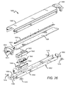
- FIG. 26 is an exploded view of the fixture according to an embodiment of the present invention with the components of the subassemblies separated to reveal the internal components.
- FIG. 27 is a perspective view of an extendable linear fixture according to an embodiment of the present invention.
- FIG. 28 is a perspective view of adjacent fixtures and an exploded view of the intermediate bridge structure according to an embodiment of the present invention.
- FIG. 29 is a right side elevation view of the extendable fixture along a transverse cutline bisecting the bridge structure according to an embodiment of the present invention.
- FIG. 30 is a schematic representation of an LED layout on a light strip that may be used in embodiments of the present invention.
- Embodiments of the present invention provide an indirect modular fixture that is particularly well-suited for use with solid state light sources, such as LEDs, to provide a surface ambient light (SAL).
- the fixture comprises two structural components: a housing subassembly and a lighting subassembly. These two subassemblies may be removably attached to operate as a singular fixture. Many different lighting subassemblies may be compatible with a single housing subassembly and vice versa.
- the housing subassembly comprises a frame that is mountable to an external structure.
- the lighting subassembly comprises the light sources and optical elements that tailor the outgoing light to achieve a particular profile. Both the shape and the arrangement of these elements provide the desired light output distribution.
- Electronics necessary to power and control the light sources may be disposed in either the housing subassembly or the lighting subassembly.
- Structural elements such as end caps, may be used to hold the fixture elements and the subassemblies in position relative to each other.
- Various mount mechanisms may be used to attach the fixture to a surface such as a ceiling or a wall.
- FIG. 1 is a perspective view of a modular light fixture 100 according to an embodiment of the present invention.
- the fixture 100 is particularly well-suited for use with solid state light emitters, such as LEDs or vertical cavity surface emitting lasers (VCSELs), for example.
- solid state light emitters such as LEDs or vertical cavity surface emitting lasers (VCSELs)
- VCSELs vertical cavity surface emitting lasers
- other kinds of light sources may also be used.
- the elongated fixture 100 comprises a housing subassembly 102 and a lighting subassembly 104 .
- the two subassemblies 102 , 104 are removably attached as shown.
- the subassemblies 102 , 104 define an internal cavity that houses several elements including the light sources and the driver electronics as shown in detail herein.
- the housing subassembly 102 is designed to work with many different lighting subassemblies such that they may be easily replaced to achieve a particular lighting effect, for example.
- FIG. 2 is a perspective view of a housing subassembly 102 according to an embodiment of the present invention.
- the housing subassembly 102 is designed to house driver electronics 202 which are mounted on an interior mount surface 204 .
- the housing subassembly 102 comprises a first end cap portion 206 on both ends of the subassembly 102 .
- At least one of the first end cap portions 206 has a receiving structure 208 designed to mate with a second end cap portion (not shown) on the lighting subassembly 104 as shown in more detail herein.
- the driver electronic component boxes comprise a backup battery box 202 a , a driver box 202 b , and a step-down converter box 202 c .
- the step-down converter box 202 c is an optional element that may be included in models requiring a non-standard voltage, for example, models for use in Canada or another country. Many different mount arrangements are possible to accommodate the necessary electronic components within the housing subassembly 102 , and many different combinations of electronic components may be used.
- FIG. 3 is a cutaway side view of the housing subassembly 102 along cut line A-A′.
- the electronic components 102 a , 102 b , 102 c are mounted on the interior mount surface 204 along the longitudinal axis of the housing subassembly 102 .
- Tabs 302 are used to aid in connecting the housing subassembly 102 with the lighting subassembly 104 .
- the housing subassembly 102 is configured to receive many different lighting subassemblies to provide a fixture having a desired optical effect.
- the housing subassembly 102 functions as a universal receiving structure for various embodiments of lighting subassemblies as discussed in more detail herein.
- the electronic components comprise a step-down converter 102 a , a driver circuit 102 b , and a battery backup 102 c .
- a driver circuit may comprise an AC/DC converter, a DC/DC converter, or both.
- the driver circuit comprises an AC/DC converter and a DC/DC converter both of which are located in the housing subassembly 102 .
- the AC/DC conversion is done in the housing subassembly 102
- the DC/DC conversion is done in the lighting subassembly 104 .
- Another embodiment uses the opposite configuration where the DC/DC conversion is done in the housing subassembly 102 , and the AC/DC conversion is done in the lighting subassembly 104 .
- both the AC/DC converter and the DC/DC converter are located in the lighting subassembly 104 . It is understood that the various electronic components may distributed in different ways in one or both of the subassemblies 102 , 104 .
- FIG. 4 a is a perspective view of an embodiment of a lighting subassembly 400 .
- FIG. 4 b is a cross-sectional view of the lighting subassembly 400 .
- This particular embodiment comprises an elongated heat sink 402 and a pair of lenses 404 that run longitudinally between first and second end caps 406 a , 406 b which function to hold the heat sink 402 and the lenses 404 together.
- the lighting subassembly 400 includes an optional sensor 408 which is housed in the end cap 406 a.
- Information from the sensor 408 is used to control the on/off state of the internal light sources to conserve energy when lighting in a particular area is not needed.
- the sensor may also be used to regulate the brightness of the sources, allowing for high and low modes of operation.
- a passive infrared (PIR) sensor 408 is used to determine when a person is in the vicinity of the fixture and thus would require light in the area. When the sensor detects a person, a signal is sent to the driver circuit and the lights are turned on, or if the lights remain on at all times, then the lights are switched to the high mode of operation. When the heat signature is no longer present, then the sources switch back to the default state (e.g., off or low mode).
- Many other types of sensors may be used such as a motion detector or an ultrasonic sensor, for example.
- FIG. 4 b is a cross-sectional view of the lighting subassembly 400 .
- at least one LED 410 on a light strip 412 is mounted on an internal surface 414 of the heat sink 402 .
- the LEDs 410 can also be mounted to other internal surfaces inside the optical chamber.
- the LEDs 410 emit light in a direction such that it is incident on a back reflector 416 .
- the back reflector 416 then redirects at least a portion of the light out of the optical chamber through the lenses 404 .
- the back side of the heat sink 402 functions as an internal surface of the lighting subassembly 400 .
- the heat sink 402 can be constructed using many different thermally conductive materials.
- the heat sink 402 may comprise an aluminum body.
- the heat sink 402 can be extruded for efficient, cost-effective production and convenient scalability.
- the heat sink 402 can be integrated with a printed circuit board (PCB), for example. Indeed the PCB itself may function as the heat sink, so long as the PCB is capable of handling thermal transmission of the heat load. Many other heat sink structures are possible.
- PCB printed circuit board
- the heat sink 402 can be mounted to the lighting subassembly 400 using various methods such as, screws, pins, or adhesive, for example.
- the heat sink 402 comprises an elongated thin body with a substantially flat area internal surface 414 on which one or more light sources can be mounted.
- the flat area provides for good thermal communication between the heat sink 402 and the light sources 410 mounted thereon.
- the light sources will be pre-mounted on light strips.
- FIGS. 5 a - c show a top plan view of portions of several light strips 500 , 520 , 540 that may be used to mount multiple LEDs to the heat sink 118 , and in some embodiments a sink may be integrated with the light strips 500 , 520 , 540 .
- LEDs are used as the light sources in various embodiments described herein, it is understood that other light sources, such as laser diodes for example, may be substituted in as the light sources in other embodiments.
- Embodiments of lighting subassemblies may comprise one or more emitters producing the same color of light or different colors of light.
- a multicolor source is used to produce white light.
- Several colored light combinations will yield white light. For example, it is known in the art to combine light from a blue LED with wavelength-converted yellow (blue-shifted-yellow or “BSY”) light to yield white light with correlated color temperature (CCT) in the range from 5000K to 7000K (often designated as “cool white”).
- BSY wavelength-converted yellow
- CCT correlated color temperature
- Both blue and BSY light can be generated with a blue emitter by surrounding the emitter with phosphors that are optically responsive to the blue light.
- the phosphors When excited, the phosphors emit yellow light which then combines with the blue light to make white. In this scheme, because the blue light is emitted in a narrow spectral range it is called saturated light. The BSY light is emitted in a much broader spectral range and, thus, is called unsaturated light.
- RGB schemes may also be used to generate various colors of light.
- an amber emitter is added for an RGBA combination.
- the previous combinations are exemplary; it is understood that many different color combinations may be used in embodiments of the present invention. Several of these possible color combinations are discussed in detail in U.S. Pat. No. 7,213,940 to Van de Ven et al.
- the lighting strips 500 , 520 , 540 each represent possible LED combinations that result in an output spectrum that can be mixed to generate white light.
- Each lighting strip can include the electronics and interconnections necessary to power the LEDs.
- the lighting strip comprises a printed circuit board with the LEDs mounted and interconnected thereon.
- the lighting strip 500 includes clusters 502 of discrete LEDs, with each LED within the cluster 502 spaced a distance from the next LED, and each cluster 502 spaced a distance from the next cluster 502 . If the LEDs within a cluster are spaced at too great distance from one another, the colors of the individual sources may become visible, causing unwanted color-striping.
- the clusters on the light strips can be compact. In some embodiments, an acceptable range of distances for separating consecutive LEDs within a cluster is not more than approximately 8 mm.
- the scheme shown in FIG. 5 a uses a series of clusters 502 having two blue-shifted-yellow LEDs (“BSY”) and a single red LED (“R”). Once properly mixed the resultant output light will have a “warm white” appearance.
- BSY blue-shifted-yellow LEDs
- R red LED
- the lighting strip 520 includes clusters 522 of discrete LEDs.
- the scheme shown in FIG. 5 b uses a series of clusters 522 having three BSY LEDs and a single red LED. This scheme will also yield a warm white output when sufficiently mixed.
- the lighting strip 540 includes clusters 542 of discrete LEDs.
- the scheme shown in FIG. 5 c uses a series of clusters 542 having two BSY LEDs and two red LEDs. This scheme will also yield a warm white output when sufficiently mixed.
- FIGS. 5 a - c The lighting schemes shown in FIGS. 5 a - c are meant to be exemplary. Thus, it is understood that many different LED combinations can be used in concert with known conversion techniques to generate a desired output light color.
- the back reflector 416 can be constructed from many different materials.
- the back reflector 416 comprises a material which allows it to be extruded for efficient, cost-effective production.
- Some acceptable materials include polycarbonates, such as Makrolon 6265 ⁇ or FR6901 (commercially available from Bayer) or BFL4000 or BFL2000 (commercially available from Sabic). Many other materials may also be used to construct the back reflector 416 .
- the back reflector 416 is easily scalable to accommodate lighting assemblies of varying length.
- the back reflector 416 is an example of one shape that may be used in the lighting subassembly 400 .
- the back reflector 416 may be designed to have several different shapes to perform particular optical functions, such as color mixing and beam shaping, for example.
- the back reflector 416 may be rigid, or it may be flexible in which case it may be held to a particular shape by compression against other surfaces.
- Emitted light may be bounced off of one or more surfaces. This has the effect of disassociating the emitted light from its initial emission angle.
- Output color uniformity typically improves with an increasing number of bounces, but each bounce has an associated optical loss.
- an intermediate diffusion mechanism e.g., formed diffusers and textured lenses
- the back reflector 416 should be highly reflective in the wavelength ranges emitted by the source(s) 122 .
- the reflector may be 93% reflective or higher. In other embodiments it may be at least 95% reflective or at least 97% reflective.
- the back reflector 416 may comprise many different materials. For many indoor lighting applications, it is desirable to present a uniform, soft light source without unpleasant glare, color striping, or hot spots.
- the back reflector 416 may comprise a diffuse white reflector such as a microcellular polyethylene terephthalate (MCPET) material or a Dupont/WhiteOptics material, for example. Other white diffuse reflective materials can also be used.
- Diffuse reflective coatings may be used on a surface of the back reflector to mix light from solid state light sources having different spectra (i.e., different colors). These coatings are particularly well-suited for multi-source designs where two different spectra are mixed to produce a desired output color point. For example, LEDs emitting blue light may be used in combination with other sources of light, e.g., yellow light to yield a white light output.
- a diffuse reflective coating may eliminate the need for additional spatial color-mixing schemes that can introduce lossy elements into the system; although, in some embodiments it may be desirable to use a diffuse surface in combination with other diffusive elements.
- the surface may be coated with a phosphor material that converts the wavelength of at least some of the light from the light emitting diodes to achieve a light output of the desired color point.
- the back reflector 416 performs a color-mixing function, effectively doubling the mixing distance and greatly increasing the surface area of the source. Additionally, the surface luminance is modified from bright, uncomfortable point sources to a much larger, softer diffuse reflection.
- a diffuse white material also provides a uniform luminous appearance in the output. Harsh surface luminance gradients (max/min ratios of 10:1 or greater) that would typically require significant effort and heavy diffusers to ameliorate in a traditional direct view optic can be managed with much less aggressive (and lower light loss) diffusers achieving max/min ratios of 5:1, 3:1, or even 2:1.
- the back reflector 416 can comprise materials other than diffuse reflectors.
- the back reflector 416 can comprise a specular reflective material or a material that is partially diffuse reflective and partially specular reflective.
- a semi-specular material may be used on the center region with a diffuse material used in the side regions to give a more directional reflection to the sides. Many combinations are possible.
- the lenses 404 may be designed to perform these functions as the light passes through it.
- the lenses 404 can comprise many different elements and materials.
- the lenses 404 comprise a diffusive element.
- a diffusive exit lens functions in several ways. For example, it can prevent direct visibility of the sources and provide additional mixing of the outgoing light to achieve a visually pleasing uniform source. However, a diffusive exit lens can introduce additional optical loss into the system. Thus, in embodiments where the light is sufficiently mixed by the back reflector 416 or by other elements, a diffusive exit lens may be unnecessary. In such embodiments, a transparent glass exit lens may be used, or the exit lens may be removed entirely. In still other embodiments, scattering particles may be included in the exit lens 104 . Some embodiments may include a specular or partially specular back reflector. In such embodiments, it may be desirable to use a diffuse exit lens.
- Diffusive elements in the lenses 404 can be achieved with several different structures.
- a diffusive film inlay can be applied to the top- or bottom-side surface of the lenses 404 . It is also possible to manufacture the lenses 404 to include an integral diffusive layer, such as by coextruding the two materials or by insert molding the diffuser onto the exterior or interior surface.
- a clear lens may include a diffractive or repeated geometric pattern rolled into an extrusion or molded into the surface at the time of manufacture.
- the exit lens material itself may comprise a volumetric diffuser, such as an added colorant or particles having a different index of refraction, for example.
- the lenses 404 may be used to optically shape the outgoing beam with the use of microlens structures, for example.
- Microlens structures are discussed in detail in U.S. patent application Ser. No. 13/442,311 to Lu, et al., which is commonly assigned with the present application to CREE, INC. and incorporated by reference herein.
- FIG. 6 is a perspective view of another lighting subassembly 600 that may be used in conjunction with the housing subassembly 102 .
- the lighting subassembly 102 is simply another exemplary embodiment of a lighting subassembly, and that many different lighting subassemblies may be used to provide a particular lighting effect.
- the lighting subassembly 600 is particularly well-suited for use with solid state light emitters, such as LEDs or vertical cavity surface emitting lasers (VCSELs), for example. However, other kinds of light sources may also be used.
- An elongated body 602 provides the primary mechanical structure for the lighting subassembly 600 .
- An exit lens 104 provides a transmissive window through which light is emitted.
- End caps 106 cover the ends of the housing 102 and hold the housing 102 and the exit lens 104 in place.
- the housing 102 , exit lens 104 , and end caps 106 define an internal cavity that houses several elements including the light sources and the driver electronics as shown in detail herein.
- a sensor 108 protrudes through the body 102 . Information from the sensor 108 is used to control the internal light sources.
- the lighting subassembly 600 can be attached to a housing assembly such as the housing assembly 102 .
- the two subassemblies 102 , 600 may be attached using a snap-fit structure, screws, or the like. In some instances a more permanent attachment mechanism may be used such as adhesive, for example.
- FIG. 7 is a perspective view of an embodiment of a modular light fixture 700 .
- the fixture comprises a housing subassembly 702 removably attached to the lighting subassembly 400 shown in FIG. 4 .
- the fixture 700 is similar to the fixture 100 shown in FIG. 1 ; however, the fixture 700 comprises a sensor 704 .
- the sensor 704 provides information to the driver circuit that is used to control the light sources.
- the sensor 704 is integral with a first end cap 706 .
- Many different kinds of sensors can be used depending on the operating environment and the nature of the objects to be sensed. In other embodiments, a sensor can be located in several different alternate positions such as along the heat sink, for example.
- FIG. 8 is a perspective view of an embodiment of a modular light fixture 800 .
- the fixture comprises a housing subassembly 802 that is removably attached to the lighting subassembly 600 shown in FIG. 6 .
- This embodiment also comprises the sensor 608 which is integral with the body 602 of the lighting subassembly 600 .
- FIG. 9 is a cut-away side view of the modular light fixture 700 .
- the housing subassembly 102 is removably attached to the lighting subassembly 400 with a snap-fit mechanism 902 , although other attachment means are possible.
- the fixture 700 is designed to provide a symmetrical light output wherein the primary direction of the light emission is straight out from the fixture 700 as shown.
- FIG. 10 is a cut-away side view of the modular light fixture 800 .
- the housing subassembly 102 is removably attached to the lighting subassembly 600 with a snap-fit mechanism 1000 , although other attachment means are possible.
- the fixture 800 is designed to provide an asymmetrical light output distribution.
- the back reflector 1004 has a curved shape approximated by a spline curve. The shape has an asymmetric transverse cross-section. The back reflector 1004 extends farther in the transverse direction on one side of the light sources 1002 than on the other side.
- the light sources 1002 are disposed off-center relative to a central longitudinal axis running through the center of the housing 102 .
- the light sources 1002 are emit at an angle that is off-center with respect to the back reflector 124 ; i.e., light emitted from the sources is incident on off-center areas of the back reflector 1004 more heavily.
- the positioning of the light sources 1002 and the asymmetric shape and placement of the back reflector 1004 result in an asymmetric light distribution.
- Such an output is useful for lighting areas where more light is required in a given direction, such as stairwell, for example. In a stairwell it is important to light stairs that descend and/or ascend from a given level; thus, an asymmetric output distribution may be used to direct more of the light into these specific areas, reducing the total amount of light that is necessary to light such as an area.
- FIG. 11 is a perspective view of an embodiment of modular light fixture 1100 .
- This particular embodiment comprises housing subassembly 1102 and a lighting subassembly 1104 that are removably attached.
- FIG. 12 is a cross-sectional view of the fixture 1100 .
- the housing subassembly 1102 and the lighting subassembly 1104 are shown detached.
- light sources 1106 and driver electronics 1108 are both housed within the lighting subassembly.
- the light sources 1106 are positioned to emit light such that it directly impinges on an exit lens 1110 and passes out of the optical chamber and into the ambient.
- the fixture 1100 is a direct lighting fixture as opposed to the indirect fixtures 600 , 800 where the light first impinges on a back reflector and is redirected with at least one internal bounce before passing through an exit lens.
- a back reflector 1112 is behind the initial direction of emission from the sources 1106 , redirecting any light that may have not have exited the chamber on the first pass because, for example, of total internal reflection at the lens 1110 .
- the two subassemblies 1102 , 1104 are attached with a hook-and-eye mechanism with the lighting subassembly 1104 comprising a hook 1114 and the housing subassembly comprising the receiving eye 1116 .
- the hook can be a component of the housing subassembly, and the eye a component of the lighting subassembly.
- FIGS. 13 a - c show perspective views of the fixture 1100 during various stages of installation.
- the lighting subassembly 1104 is temporarily suspended from the housing subassembly 1102 by inserting the hooks 1114 into the receiving eyes 1116 such that the internal surfaces of both subassemblies 1102 , 1104 are facing away from the mount surface, toward the installer.
- the wiring connections 1118 are made joining the wires bringing power from an outside source to the wires connected to the light sources in the lighting subassembly 1104 .
- FIG. 13 a the lighting subassembly 1104 is temporarily suspended from the housing subassembly 1102 by inserting the hooks 1114 into the receiving eyes 1116 such that the internal surfaces of both subassemblies 1102 , 1104 are facing away from the mount surface, toward the installer.
- the wiring connections 1118 are made joining the wires bringing power from an outside source to the wires connected to the light sources in the lighting subassembly 1104
- the lighting subassembly 1104 is swiveled up about the hooks 1114 and fastened to the housing subassembly 1102 , using for example, a snap-fit structure.
- the wiring connections 1118 are then enclosed within the fixture. It is understood that the method and structures shown in FIGS. 13 a - c are merely exemplary and that many different mechanisms can be used to attach the two subassemblies 1102 , 1104 during installation.
- FIGS. 14 a - c are perspective views of an embodiment of a modular lighting fixture 1400 .
- the fixture 1400 comprises a housing subassembly 1402 and a lighting subassembly 1404 that are removably attached.
- the end caps 1406 are separate components rather than an integral part of either subassembly.
- the fixture 1400 can be mounted to a wall ( FIG. 14 a ), mounted to a ceiling ( FIG. 14 b ), mounted to another surface, or it can be suspended from the ceiling in a pendant configuration ( FIG. 14 c ).
- FIG. 15 is an exploded view of the modular lighting fixture 1400 that is mounted to a ceiling.
- the lighting subassembly includes a set of tether clips 1408 that correspond to a set of flanges 1410 on the housing subassembly 1402 .
- the tether clips 1408 are hooked over the flanges 1410 such that the lighting subassembly 1404 may be suspended temporarily from the housing subassembly 1402 which is mounted firmly to the ceiling surface.
- the lighting subassembly 1404 can be swung up to connect to the housing subassembly 1402 with a hook-and-slot mechanism as shown.
- the lighting assembly 1404 hook is aligned with the slot and then slides laterally to engage the housing subassembly 1402 .
- Other mechanisms can be used to attach the subassemblies 1402 , 1404 such as a snap-fit structure or the like.
- the end caps 1406 are placed over the ends of both subassemblies 1402 , 1404 .
- the end caps 1406 may be fastened to the subassemblies 1402 , 1404 using a similar snap-fit mechanism, screws, or other structures.
- the end caps 1406 may also serve to hold the subassemblies firmly together and complete the electronic enclosure.
- the driver electronics 1412 are mounted to an interior surface 1414 of the lighting subassembly 1404 .
- the interior surface 1414 can accommodate other electronic components as necessary.
- the components on the interior surface 1414 of the lighting assembly 1404 fold into the space hollow space within the housing assembly 1402 .
- Several knockouts 1416 are disposed along the housing subassembly 1402 . The knockouts 1416 can be removed to feed wiring into the housing subassembly 1402 for connection with the driver electronics 1412 .
- FIG. 16 is a perspective view of an embodiment of a modular light fixture 1600 .
- the fixture 1600 is similar to the fixture 1400 also comprising a housing subassembly 1602 that is removably attached to a lighting subassembly 1604 .
- the fixture 1600 includes end caps 1606 wherein one of the end caps 1606 has a built-in sensor 1608 to provide information to the drive electronics to control the light sources.
- a test/reset button 1610 is also included to facilitate maintenance by providing a convenient way to check the operation of the sensor 1608 , the light sources, or another electronic component without having to detach the subassemblies 1602 , 1604 .
- FIGS. 17 a - c show perspective views of an end cap 1700 that may be used in embodiments of present invention.
- the end cap 1700 attaches to the ends of fixtures similar to the fixture 1400 .
- the end cap 1700 comprises knockout portions 1702 that may be removed to provide a pathway for wires running into the fixture housing.
- FIG. 17 b shows the end cap 1702 after one of the knockouts has been removed.
- FIG. 17 c shows the back side of the end cap 1702 which features a ridge 1704 that outlines a part of the footprint of the knockout 1702 .
- the ridge 1704 provides a smooth reinforced surface for the space that exists after the knockout 1702 is removed.
- FIGS. 18 a - c shows an embodiment of an extended modular fixture 1800 .
- FIG. 18 a shows two smaller linear fixtures 1802 a , 1802 b , which are similar to the fixture 1400 in many respects, that have been attached together to form the extended fixture 1800 .
- the intermediate joiner plate 1804 provides the attachment mechanism.
- the individual fixtures 1802 a , 1802 b can be separately connected to a power sources or then can be serially connected with wires passing through the joiner structure 1804 to complete the electrical connection. In this way, additional fixtures may be added to the ends to extend the fixture 1800 in either direction, for example, to light a continuous corridor.
- FIGS. 18 b and 18 c show the fixture 1800 before the small fixtures 1802 a , 1802 b have been connected.
- the joiner structure comprises mount plate 1806 and a sleeve 1808 .
- the mount plate is attached using screws, for example, to the fixtures 1802 a , 1802 b , and the sleeve 1808 wraps around to cover the interface.
- the extended modular fixture 1800 is a ceiling-mounted embodiment. However, it is understood that fixtures may be mounted using other methods, for example, wall-mount, surface-mount, or pendant-mount configurations. Such fixtures may be similarly joined together to create an extended modular fixture having a particular desired length.
- FIG. 19 is a perspective view of a modular light fixture 1900 according to an embodiment of the present invention.
- the fixture 1900 comprises a housing subassembly 1902 and a lighting subassembly 1904 that are removably attached to one another.
- the lighting subassembly 1904 includes at least one end cap 1906 and a wrap body 1908 .
- the end caps 1906 are shaped to fit snugly over one or both longitudinal ends of the wrap body 1908 .
- the end caps 1906 also provide the structure by which the lighting subassembly 1904 and the housing subassembly 1902 are attached as discussed in more detail herein.
- the front side of the wrap body 1908 comprises an exit lens 1910 .
- the fixture 1900 is particularly well-suited for mounting to a surface, such as a ceiling or a wall, but it also may be pendant mounted (i.e., suspended) with chains or the like.
- a surface such as a ceiling or a wall
- pendant mounted i.e., suspended
- the housing subassembly 1902 is almost entirely obscured from observer view.
- FIG. 20 is a right end elevation view of the light fixture 1900 .
- the end cap 1906 covers most of the housing subassembly 1902 , although some of the housing subassembly 1902 is accessible (by removing knockouts 1912 ) to allow wiring to pass into the fixture 1900 from the ends, for example, for serial connection with additional fixtures.
- the housing subassembly 1902 and lighting subassembly 1904 are removably attached with female and male attachment structures 1914 , 1916 as discussed in more detail herein.
- the housing subassembly 1902 also comprises a screw plate 1917 which is shaped to cooperate with a screw tab 1919 on the end cap 1906 .
- Both the screw tab 1919 and the screw plate 1917 are angled to obscure them from head-on front side view.
- the screw plate 1917 and the screw tab 1919 may be fastened together with a screw 1921 after the subassemblies 1902 , 1904 have been snap fit together to provide a redundant fastening mechanism.
- This additional fastener may be used to prevent the subassemblies 1902 , 1904 from unintentional detachment, for example, if the male attachment structures 1916 were accidentally depressed during cleaning.
- FIGS. 21 a - f represent various elevation views of the fixture 1900 :
- FIG. 21 a is an internal view of the end of the fixture 1900 from cutline a-a;
- FIG. 21 b is a front elevation view of the fixture 1900 ;
- FIG. 21 c is a right end elevation view of the fixture 1900 , with the left end view being identical;
- FIG. 21 d is a right side elevation view of the fixture 1900 , with the left side view being identical;
- FIG. 21 e is a back elevation view of the fixture 1900 .
- FIG. 21 a the left internal end is shown from a vantage point inside the fixture 1900 (i.e., from cutline a-a). Thus, the internal elements of the fixture 1900 are visible as discussed in more detail herein.
- FIG. 21 d shows a plurality of ridges 1918 that run longitudinally along the wrap body 1908 .
- the lighting subassembly 1904 comprises an opaque portion 1920 that starts at the ridges 1918 and extends away from the exit lens 1910 .
- the exit lens 1910 and the opaque portion 1920 may be coextruded as a single structure to form the wrap body 1908 , or the two components may be manufactured separately and attached afterward.
- FIG. 21 e shows the back side of the fixture 1900 .
- the housing subassembly 1902 comprises several mount features 1922 for mounting the fixture 1900 to a surface, such as a ceiling or a wall, or for suspending it from a surface.
- Knockouts/holes 1924 provide access to the internal components of the fixture. In other embodiments, mount features and knockouts/holes can be added or moved as necessary to accommodate a particular mount configuration.
- FIG. 22 is a perspective view of the fixture 1900 with the housing subassembly 1902 and the lighting subassembly 1904 detached.
- the lighting subassembly 1904 slides over the housing subassembly 1902 until the male attachment structures 1916 on the housing subassembly 1902 snap into place within the female attachment structures 1914 on the lighting subassembly 1904 , securing the two subassemblies 1902 , 1904 together.
- a male attachment structure 1916 is attached to each corner of the housing subassembly 1902 .
- the male attachment structures 1916 may be attached to the housing subassembly 1902 using screws, adhesives, or the like.
- the female attachment structures 1914 are defined by cutaway portions of the end caps 1906 .
- the attach/detach mechanism allows for the housing subassembly 1902 to remain mounted to a surface while the lighting subassembly 1904 is easily and safely removed for maintenance or replacement.
- the exit lens 1910 is translucent such that the internal components are visible.
- a plurality of light sources 1926 on a platform 1928 can be seen through the exit lens 1910 .
- This particular lighting subassembly 1904 provides a direct lighting scheme. That is, a significant portion of the light emitted from the sources 1926 passes through the exit lens 1910 without first being redirected by another surface within the fixture 1900 .
- Other embodiments may include internal reflective surfaces that interact with the light prior to emission from the fixture. Indeed, many different internal optical configurations are possible to achieve a particular output profile.
- FIG. 23 is a perspective views of the fixture 1900 with one of the end caps 1906 removed to reveal the internal elements.
- the light sources 1926 are on the platform 1928 , both of which are surrounded on three sides by exit lens 1910 portion of the wrap body 1908 .
- the platform 1928 is adjacent to the housing subassembly 1902 as shown in more detail in FIG. 24 .
- FIG. 24 is an elevation view of the fixture 1900 with the end cap 1906 removed to reveal the internal elements.
- the end cap 1906 may be attached to the wrap body 1908 with screws, adhesives, or the like.
- bore holes 1930 on both sides of the wrap body 1908 receive screws that fasten the end cap 1906 thereto to complete the lighting subassembly 1904 structure.
- the wrap body 1908 comprises the exit lens 1910 and the opaque portion 1920 .
- the exit lens 1910 constitutes the portion of the wrap body 1908 toward the front of the lighting subassembly 1904 , with the opaque portion 1920 beginning at the ridges 1918 and extending toward the back of the lighting subassembly 1904 .
- the wrap body may be coextruded as a monolithic element, or the exit lens 1910 and the opaque portion 1920 can be manufactured separately and then attached to form the wrap body 1908 .
- the light sources 1926 are on a light strip 1932 , similar to those described herein with reference to FIGS. 5 a - c , which is then affixed to the front side mount surface of the platform 1928 .
- the platform 1928 slides into locking channels 1935 which are defined by internal flanges 1934 that protrude in from the wrap body 1908 .
- the platform 1928 and the exit lens 1910 define an optical cavity 1936 .
- the distance (d) from the top of the light sources 1926 to the exit lens 1910 is approximately 46.34 mm, measured orthogonally from a point along a central longitudinal axis to the inner surface of the exit lens 1910 .
- a range of distances d may be used in various embodiments.
- d ranges between 46.34 ⁇ 5 mm.
- Other embodiments may have d ranging between 46.34 ⁇ 10 mm.
- d ranges from 46.34 ⁇ 15 mm.
- Surfaces of the flanges 1934 and the platform 1928 that face the optical cavity 1936 are reflective so that any light incident on those surfaces is redirected back toward the exit lens 1910 .
- the internal side surfaces 1938 are textured or coated to give them a diffusive quality. For example, a sawtooth pattern may be rolled into these surfaces 1938 to provide the required texturing. This diffusive treatment reduces any imaging (or pixilation) of the light sources 1926 visible from the sides of the fixture 1900 .
- FIG. 25 is an elevation view of the end cap 1906 , which has been removed from the wrap body 1908 .
- the end cap is shaped to define the female attachment structures 1914 .
- These structures 1914 include a tapered lead-in surface to urge the male attachment structures 1916 into a snap-fit arrangement when the housing subassembly 1902 engages with the end cap 1906 .
- the screw tab 1919 can be attached affixed to the screw plate 1917 of the housing subassembly 1902 to provide the redundant attachment mechanism.
- the end cap 1906 is shaped to define an access space 1940 so that wires can be fed into the housing subassembly 1902 when attached thereto.
- the access space 1940 allows for easy access to the knockouts 1912 that can be removed to provide a conduit to internal components.
- Screw holes 1942 may be used to attach the end cap 1906 to the wrap body 1908 .
- the end cap 1906 also features a recessed portion 1944 that protrudes slightly into the internal space of the fixture 1900 .
- the recessed portion 1944 may feature snap-fit indentations or other mechanical features to facilitate serial connection.
- FIG. 26 is an exploded view of the fixture 1900 with the components of the subassemblies 1902 , 1904 separated to reveal the internal components.
- the light strip 1926 is mounted to the platform 1928 on the front side, using screws or a thermal adhesive for example.
- Driver electronics 1946 are arranged on the back side of the platform 1928 , opposite but proximate to the light sources 1926 that they power.
- the driver electronics 1946 are disposed within a driver housing 1948 that is mounted to the platform 1928 .
- An insulator 1950 separates the electronics 1946 from the housing 1948 .
- Thermal pads 1952 may be used to facilitate thermal conduction from the electronics 1946 to the platform 1928 and the housing subassembly 1902 for dissipation into the ambient.
- the driver electronics 1946 are housed within the lighting subassembly 1904 ; however, as discussed herein, it is understood that in other embodiments the driver electronics may be housed within the housing subassembly. In still other embodiments, components of the driver electronics may distributed in both the housing subassembly and the lighting subassembly.
- the housing subassembly 1902 comprises a wrap frame 1954 and end plates 1956 at both ends. As previously discussed, the end plates 1956 comprise knockouts 1912 to allow access to the light sources 1926 and the driver electronics 1946 .
- the housing subassembly 1902 may be constructed from many different materials, with cold rolled steel being one acceptable material.
- the fixture 1900 may come in various lengths, with some suitable lengths being 4 feet, 2 feet, and 3 feet. Many different base lengths are possible. Some applications require fixtures having longer lengths, such as aisles in a grocery market, for example. In such cases, the fixture 1900 may be serially connected (i.e., daisy-chained) with additional fixtures to achieve the desired aggregate length.
- FIG. 27 is a perspective view of an extendable linear fixture 2700 according to an embodiment of the present invention.
- the extendable fixture 2700 comprises a plurality of identical fixtures 1900 similar to the fixture 1900 .
- An intermediate bridge structure 2702 is arranged between adjacent fixtures 1900 to connect them.
- FIG. 28 is a perspective view of adjacent fixtures 1900 and an exploded view of the intermediate bridge structure 2702 .
- the bridge structure 2702 comprises an extension piece 2704 and a bracket 2706 .
- the extension piece 2704 is shaped to mimic that of the wrap body 1908 such that bridge structure 2702 is scarcely noticeable to an observer.
- the bracket 2706 connects to the back side of the adjacent fixtures 1900 with screws or the like.
- Flanges 2708 at the base of the extension piece is shaped to mate with a ridge 2710 on the front side of the bracket 2706 .
- the intermediate bridge structure 2702 and adjacent end caps 1906 define an intermediate enclosure 2712 between the fixtures 1900 where wiring may pass between the fixtures 1900 to achieve the serial connection. Wires may also be routed into the intermediate enclosure 2712 from outside by removing the bracket knockouts 2714 .
- the bridge structure 2702 provides protection for the wiring and obscures the unsightly connections from view.
- FIG. 29 is a right side elevation view of the extendable fixture 2700 along a transverse cutline bisecting the bridge structure 2702 .
- the spring force of the slightly compressed extension piece 2704 urges the flanges 2708 outward against the bracket ridge 2710 such that the extension piece 2704 is held in place between adjacent end caps 1906 .
- the recessed portion 1944 of the end caps 1906 may comprise a transmissive material or may be removed altogether to provide some side light into the intermediate enclosure 2712 to further camouflage the bridge structure 2702 during operation.
- FIG. 30 is a schematic representation of an LED layout on a light strip 3000 that may be used in light fixtures according to embodiments of the present invention.
- the LEDs are arranged in clusters 3002 with each cluster 3002 comprising five discrete light sources: four BSY LEDs (marked BSY) and one red LED (marked R).
- the BSY LEDs are arranged in a diamond pattern with the red LED in the middle.
- Each of the LEDs has a square footprint and is rotated 45° such that none of the sides of the LEDs run parallel to the edge of the light strip 3000 . It is understood that, in other embodiments, different color combinations may be used and that the LEDs may be arranged and/or rotated in many different ways to achieve a desired output profile.
- the clusters 3002 are spaced longitudinally along the center of the light strip 3000 at an even interval.
- the distance between the edge of one cluster 3002 and the edge of an adjacent cluster 3002 is approximately 12.25 mm.
- the distance between adjacent LEDs around the perimeter of the diamond is approximately 8.65 mm.
- the distance from each LED on the perimeter to the center LED is approximately 5 mm.
- the clusters 3002 are arranged in the middle of the light strip 3000 at a distance of approximately 7.5 mm from the lateral edge of the light strip 3000 , measured from the edge of the light strip 3000 to the closest LED as shown. It is understood that the arrangement shown in FIG. 30 is merely exemplary.
- the light sources may be spaced differently within each cluster, and the clusters may be spaced at different intervals along the light strip.
- Embodiments of the present invention may incorporate various ornamental features to provide an aesthetically pleasing product for installation in residential, commercial, and industrial environments.
- Several embodiments of such lighting fixtures are disclosed in U.S. Design Pat. App. Ser. No. 29/462,422, titled “SURFACE AMBIENT WRAP LIGHT FIXTURE”, which is commonly owned with the present application and filed concurrently herewith. The application referenced in this paragraph is incorporated by reference as if set forth fully herein.
Landscapes
- Engineering & Computer Science (AREA)
- General Engineering & Computer Science (AREA)
- Microelectronics & Electronic Packaging (AREA)
- Architecture (AREA)
- Power Engineering (AREA)
- Arrangement Of Elements, Cooling, Sealing, Or The Like Of Lighting Devices (AREA)
- Non-Portable Lighting Devices Or Systems Thereof (AREA)
Abstract
Description
Claims (32)
Priority Applications (1)
| Application Number | Priority Date | Filing Date | Title |
|---|---|---|---|
| US13/958,461 US9874333B2 (en) | 2013-03-14 | 2013-08-02 | Surface ambient wrap light fixture |
Applications Claiming Priority (2)
| Application Number | Priority Date | Filing Date | Title |
|---|---|---|---|
| US13/829,558 US10584860B2 (en) | 2013-03-14 | 2013-03-14 | Linear light fixture with interchangeable light engine unit |
| US13/958,461 US9874333B2 (en) | 2013-03-14 | 2013-08-02 | Surface ambient wrap light fixture |
Related Parent Applications (1)
| Application Number | Title | Priority Date | Filing Date |
|---|---|---|---|
| US13/829,558 Continuation-In-Part US10584860B2 (en) | 2013-03-14 | 2013-03-14 | Linear light fixture with interchangeable light engine unit |
Publications (2)
| Publication Number | Publication Date |
|---|---|
| US20140268748A1 US20140268748A1 (en) | 2014-09-18 |
| US9874333B2 true US9874333B2 (en) | 2018-01-23 |
Family
ID=51526289
Family Applications (1)
| Application Number | Title | Priority Date | Filing Date |
|---|---|---|---|
| US13/958,461 Active US9874333B2 (en) | 2013-03-14 | 2013-08-02 | Surface ambient wrap light fixture |
Country Status (1)
| Country | Link |
|---|---|
| US (1) | US9874333B2 (en) |
Cited By (13)
| Publication number | Priority date | Publication date | Assignee | Title |
|---|---|---|---|---|
| US20170038037A1 (en) * | 2015-08-07 | 2017-02-09 | Ningbo Haider Import And Export Co., Limited | Led strip housing apparatus |
| US20170314765A1 (en) * | 2016-04-29 | 2017-11-02 | Vodce Lighting, LLC | Luminaire illumination and power distribution system |
| USD901751S1 (en) * | 2018-08-20 | 2020-11-10 | Lei Ye | Triple-proof lamp shade |
| USD917091S1 (en) * | 2019-01-25 | 2021-04-20 | Zenan Ma | Magnetic lamp |
| US10989372B2 (en) | 2017-03-09 | 2021-04-27 | Ecosense Lighting Inc. | Fixtures and lighting accessories for lighting devices |
| US11022279B2 (en) | 2016-03-08 | 2021-06-01 | Ecosense Lighting Inc. | Lighting system with lens assembly |
| US11028980B2 (en) | 2013-10-30 | 2021-06-08 | Ecosense Lighting Inc. | Flexible strip lighting apparatus and methods |
| US11041609B2 (en) | 2018-05-01 | 2021-06-22 | Ecosense Lighting Inc. | Lighting systems and devices with central silicone module |
| US11296057B2 (en) | 2017-01-27 | 2022-04-05 | EcoSense Lighting, Inc. | Lighting systems with high color rendering index and uniform planar illumination |
| US11353200B2 (en) | 2018-12-17 | 2022-06-07 | Korrus, Inc. | Strip lighting system for direct input of high voltage driving power |
| US11353178B2 (en) * | 2020-11-10 | 2022-06-07 | Ideal Industries Lighting Llc | Lighting fixtures with LED modules configured for tool-less attachment |
| US11940121B2 (en) | 2022-08-30 | 2024-03-26 | Abl Ip Holding Llc | Light fixture for ceiling grid |
| US12388056B1 (en) | 2017-01-27 | 2025-08-12 | Korrus, Inc. | Linear lighting systems and processes |
Families Citing this family (28)
| Publication number | Priority date | Publication date | Assignee | Title |
|---|---|---|---|---|
| WO2013059298A1 (en) | 2011-10-17 | 2013-04-25 | Ecosense Lighting Inc. | Linear led light housing |
| US20140169025A1 (en) * | 2012-12-15 | 2014-06-19 | Lumenetix, Inc. | System and method for mixing and guiding light emitted from light emitting diodes to a light pipe for emission in a linear configuration |
| US10900653B2 (en) * | 2013-11-01 | 2021-01-26 | Cree Hong Kong Limited | LED mini-linear light engine |
| DE202014101985U1 (en) * | 2014-04-28 | 2015-07-30 | Zumtobel Lighting Gmbh | Arrangement for forming an elongated, channel-like receiving space |
| US9822937B2 (en) | 2014-06-16 | 2017-11-21 | Abl Ip Holding Llc | Light engine retrofit kit and method for installing same |
| CN204285102U (en) * | 2014-07-04 | 2015-04-22 | 东莞嘉盛照明科技有限公司 | Lighting device |
| US9453620B2 (en) * | 2014-10-08 | 2016-09-27 | Orion Energy Systems, Inc. | Strip fixture retrofit systems and methods |
| KR101502960B1 (en) * | 2014-10-29 | 2015-03-17 | 농업회사법인 주식회사 퓨쳐그린 | LED lighting module for optimizing inception growth efficiency of plant, LED lighting apparatus for plant-culture factory using the same |
| CA2919802C (en) | 2015-02-04 | 2019-02-26 | Stephen Barry Mccane | Easy install light engine retrofit kit and method for using same |
| US9574751B1 (en) * | 2015-02-27 | 2017-02-21 | Cooper Technologies Company | Flexible luminaire |
| DE202016100264U1 (en) * | 2016-01-21 | 2017-04-24 | Zumtobel Lighting Gmbh | Lighting system with an arrangement for forming an elongated receiving space for lighting units |
| US10429041B2 (en) * | 2016-02-24 | 2019-10-01 | Power Concepts, Llc | Ceiling light retrofit kit having a light panel and two profiles to surround preexisting base of a light fixture |
| IT201600073141A1 (en) * | 2016-07-13 | 2016-10-13 | Cherry Merry Lab S R L | EXTERNAL SURFACE SHELL FOR ILLUMINATING PROFILE, WITH FIXING THROUGH PEIGATURA IN THE ASSEMBLY PHASE |
| FR3056699B1 (en) * | 2016-09-26 | 2019-06-28 | Valeo Vision | LUMINOUS MODULE AND LUMINOUS DEVICE FOR SELF-MOVING VEHICLE COMPRISING SUCH A LIGHT MODULE |
| DE202016106102U1 (en) * | 2016-10-31 | 2018-02-01 | Rehau Ag + Co | lighting device |
| US10247372B2 (en) * | 2017-02-06 | 2019-04-02 | Cree, Inc. | LED troffer lens assembly mount |
| USD927027S1 (en) | 2017-02-06 | 2021-08-03 | Ideal Industries Lighting Llc | LED troffer |
| WO2018202553A1 (en) * | 2017-05-01 | 2018-11-08 | Philips Lighting Holding B.V. | A light emitting device with a led strip |
| DE202018100522U1 (en) * | 2018-01-31 | 2019-05-03 | Zumtobel Lighting Gmbh | Lighting system |
| US11713873B2 (en) * | 2019-04-15 | 2023-08-01 | Project Light, Llc | Lighted mirror assembly |
| JP2020057629A (en) * | 2020-01-07 | 2020-04-09 | 三菱電機株式会社 | lighting equipment |
| JP6991266B2 (en) * | 2020-04-21 | 2022-02-15 | 三菱電機株式会社 | Lighting equipment |
| US11585499B2 (en) * | 2020-09-07 | 2023-02-21 | Xiamen Eco Lighting Co. Ltd. | Lighting apparatus |
| IT202100014735A1 (en) * | 2021-06-07 | 2022-12-07 | Nexty Arte S R L | HOMOGENEOUS LIGHTING SYSTEM FOR LARGE SPACE ENVIRONMENTS |
| JP7478349B2 (en) * | 2021-11-26 | 2024-05-07 | 東芝ライテック株式会社 | lighting equipment |
| USD1101247S1 (en) | 2022-07-25 | 2025-11-04 | Abl Ip Holding, Llc | Ceiling light fixture |
| CN115539857A (en) * | 2022-09-15 | 2022-12-30 | 厦门普为光电科技有限公司 | Tri-proof lamp with replaceable induction lamp holder |
| USD1086088S1 (en) * | 2022-09-23 | 2025-07-29 | Bloodhound Tracking Device, Inc. | Internal electronics housing |
Citations (136)
| Publication number | Priority date | Publication date | Assignee | Title |
|---|---|---|---|---|
| US3589660A (en) | 1970-03-05 | 1971-06-29 | Nat Service Ind Inc | Lighting fixture hanger |
| US4118763A (en) | 1976-04-12 | 1978-10-03 | General Electric Company | Variable transmission prismatic refractors |
| US4300185A (en) | 1979-12-07 | 1981-11-10 | C. W. Cole & Company, Inc. | Light fixture unit for open plan office |
| US4464707A (en) | 1982-03-17 | 1984-08-07 | Louis Forrest | Lighting fixture |
| US4472767A (en) | 1981-12-23 | 1984-09-18 | Mcgraw-Edison Company | Reflector assembly for indirect or semi-indirect lighting fixture |
| US4946547A (en) | 1989-10-13 | 1990-08-07 | Cree Research, Inc. | Method of preparing silicon carbide surfaces for crystal growth |
| US5200022A (en) | 1990-10-03 | 1993-04-06 | Cree Research, Inc. | Method of improving mechanically prepared substrate surfaces of alpha silicon carbide for deposition of beta silicon carbide thereon and resulting product |
| US5335890A (en) | 1992-07-20 | 1994-08-09 | Pryor Products, Inc. | Ceiling track mounting apparatus |
| USRE34861E (en) | 1987-10-26 | 1995-02-14 | North Carolina State University | Sublimation of silicon carbide to produce large, device quality single crystals of silicon carbide |
| US5530628A (en) | 1993-04-05 | 1996-06-25 | Peerless Lighting Corporation | Task light |
| US5653412A (en) | 1994-11-14 | 1997-08-05 | Cooper Industries, Inc. | Track mounting clip for a track lighting system |
| US5690415A (en) | 1995-11-29 | 1997-11-25 | Stylmark, Inc. | Display light |
| US5823663A (en) | 1996-10-21 | 1998-10-20 | National Service Industries, Inc. | Fluorescent troffer lighting fixture |
| US5907218A (en) | 1996-12-09 | 1999-05-25 | The Whitaker Corporation | Fluorescent lighting assembly with integral ballast |
| US5951150A (en) * | 1997-09-11 | 1999-09-14 | Eaton Corporation | Display system |
| US6190198B1 (en) | 1996-03-21 | 2001-02-20 | Peter Ray | Electrical fittings for suspended ceilings |
| US6210025B1 (en) | 1999-07-21 | 2001-04-03 | Nsi Enterprises, Inc. | Lensed troffer lighting fixture |
| US20010048599A1 (en) | 2000-05-10 | 2001-12-06 | Jean-Marc Hess | Light distributor for a lighting device and lighting device and use of a lighting device |
| US6435697B1 (en) * | 2001-02-02 | 2002-08-20 | Joseph E. Simmons | Exterior lighting system |
| US6536924B2 (en) * | 2001-02-28 | 2003-03-25 | Jji Lighting Group, Inc. | Modular lighting unit |
| US6667451B1 (en) * | 2003-03-20 | 2003-12-23 | Eaton Corporation | Push button assembly |
| US6739734B1 (en) | 2003-03-17 | 2004-05-25 | Ultimate Presentation Sytems, Inc. | LED retrofit method and kit for converting fluorescent luminaries |
| US20040109330A1 (en) | 2002-12-04 | 2004-06-10 | Jean Pare | Illuminated LED street sign |
| US20040240214A1 (en) | 2003-05-28 | 2004-12-02 | Hubbell Incorporated. | Light fixture having air ducts |
| US20040252521A1 (en) | 2003-06-13 | 2004-12-16 | Finelite | Free-cavity, double-diffusing indirect lighting luminaire |
| US20050041418A1 (en) * | 2003-08-19 | 2005-02-24 | Ben Fan | Neon light using a rope light as a light source |
| US6914194B2 (en) | 2003-10-29 | 2005-07-05 | Ben Fan | Flexible LED cable light |
| US20050146867A1 (en) | 2003-12-31 | 2005-07-07 | Kassay Charles E. | Fluorescent lighting fixtures with controlled uplight capability |
| US20060050505A1 (en) | 2002-05-28 | 2006-03-09 | Kenall Manufacturing Company | Selectively-extendable modular lighting fixture and method |
| US7131747B1 (en) | 2003-12-29 | 2006-11-07 | Yates James P | Length adjustment device for illuminated fascia |
| US20060266955A1 (en) | 2005-05-24 | 2006-11-30 | Dubois Equipment Company, Inc. | Apparatus for curing a coating on a three-dimensional object |
| US20060278882A1 (en) | 2005-06-10 | 2006-12-14 | Cree, Inc. | Power lamp package |
| US7213940B1 (en) | 2005-12-21 | 2007-05-08 | Led Lighting Fixtures, Inc. | Lighting device and lighting method |
| US7217023B2 (en) | 2002-08-01 | 2007-05-15 | Toyoda Gosei Co., Ltd. | Linear luminous body and linear luminous structure |
| US7228253B2 (en) | 2004-08-19 | 2007-06-05 | Pacific Telescope Corp. | Instrument mounting system with dual encoders |
| US20070158668A1 (en) | 2005-08-25 | 2007-07-12 | Cree, Inc. | Close loop electrophoretic deposition of semiconductor devices |
| US20070171647A1 (en) | 2006-01-25 | 2007-07-26 | Anthony, Inc. | Control system for illuminated display case |
| WO2008003289A2 (en) | 2006-07-06 | 2008-01-10 | Osram Gesellschaft mit beschränkter Haftung | Illuminating system of flexible shape |
| US20080128723A1 (en) | 2006-12-04 | 2008-06-05 | Siew It Pang | Low Thermal Resistance High Power LED |
| US7387410B2 (en) | 2004-09-07 | 2008-06-17 | C.E.I.T. Corp. | Luminaire assembly and method |
| US20080173884A1 (en) | 2007-01-22 | 2008-07-24 | Cree, Inc. | Wafer level phosphor coating method and devices fabricated utilizing method |
| US20080179611A1 (en) | 2007-01-22 | 2008-07-31 | Cree, Inc. | Wafer level phosphor coating method and devices fabricated utilizing method |
| US20080258130A1 (en) | 2007-04-23 | 2008-10-23 | Bergmann Michael J | Beveled LED Chip with Transparent Substrate |
| US20080285267A1 (en) | 2007-04-10 | 2008-11-20 | Ledalite Architectural Products, Inc. | Light control device exhibiting batwing luminous intensity distributions in upper and lower hemispheres |
| US20080314944A1 (en) | 2007-06-21 | 2008-12-25 | Cheng-Yu Tsai | Assembly for fixing and connecting light bar lamp |
| US20090009999A1 (en) | 2007-07-06 | 2009-01-08 | Bily Wang | LED lamp structure and system with high-efficiency heat-dissipating function |
| US20090040782A1 (en) | 2007-08-08 | 2009-02-12 | Ledtech Electronics Corp. | Led lighting device |
| US20090046457A1 (en) | 2007-08-13 | 2009-02-19 | Everhart Robert L | Solid-state lighting fixtures |
| US7520636B2 (en) | 2005-11-11 | 2009-04-21 | Koninklijke Philips Electronics N.V. | Luminaire comprising LEDs |
| US7540627B2 (en) | 2006-05-08 | 2009-06-02 | Innovative Lighting, Inc. | Channel light system with pivotable connector |
| US20090161356A1 (en) | 2007-05-30 | 2009-06-25 | Cree Led Lighting Solutions, Inc. | Lighting device and method of lighting |
| US7559672B1 (en) | 2007-06-01 | 2009-07-14 | Inteled Corporation | Linear illumination lens with Fresnel facets |
| US20090184333A1 (en) | 2008-01-17 | 2009-07-23 | Foxsemicon Integrated Technology, Inc. | Light emitting diode device |
| US20090185379A1 (en) | 2008-01-23 | 2009-07-23 | Chia-Yi Chen | LED light device having heat dissipating structure |
| US20090207602A1 (en) | 2005-09-06 | 2009-08-20 | Reed Mark C | Linear lighting system |
| US20090212304A1 (en) | 2008-02-22 | 2009-08-27 | Bily Wang | Led chip package structure with multifunctional integrated chips and a method for making the same |
| US20090224265A1 (en) | 2008-03-05 | 2009-09-10 | Bily Wang | LED chip package structure with a high-efficiency heat-dissipating substrate and method for making the same |
| US7591578B2 (en) | 2006-01-21 | 2009-09-22 | Hon Hai Precision Industry Co., Ltd. | Edge type backlight module having a reflective plate |
| US20090290348A1 (en) | 2006-04-16 | 2009-11-26 | Peter Van Laanen | Thermal Management Of LED-Based Lighting Systems |
| US20090290345A1 (en) | 2008-05-20 | 2009-11-26 | Apl Ip Holding Llc | Enclosures for led circuit boards |
| US20090296381A1 (en) * | 2008-06-01 | 2009-12-03 | Jack Dubord | Adjustable modular lighting system and method of using same |
| US7628506B2 (en) | 2005-10-03 | 2009-12-08 | Orion Energy Systems, Inc. | Modular light fixture with power pack and radiative, conductive, and convective cooling |
| US20100002426A1 (en) | 2008-06-25 | 2010-01-07 | Hubbell Incorporated | Multi-directional lighting fixture |
| US20100014289A1 (en) | 2007-06-13 | 2010-01-21 | ElectraLED Inc. | Multiple use LED light fixture |
| US7654703B2 (en) | 2004-01-28 | 2010-02-02 | Koninklijke Philips Electronics, N.V. | Directly viewable luminaire |
| KR20100012997A (en) | 2008-07-30 | 2010-02-09 | 한밭대학교 산학협력단 | Automatic toothpaste extruder |
| US7674005B2 (en) | 2004-07-29 | 2010-03-09 | Focal Point, Llc | Recessed sealed lighting fixture |
| US20100110701A1 (en) | 2008-10-30 | 2010-05-06 | Fu Zhun Precision Industry (Shen Zhen) Co., Ltd. | Led lamp |
| US7722220B2 (en) | 2006-05-05 | 2010-05-25 | Cree Led Lighting Solutions, Inc. | Lighting device |
| US20100128485A1 (en) | 2008-07-23 | 2010-05-27 | Ledtech Electronics Corp. | Custom assembly light-emitting module |
| US20100142205A1 (en) | 2008-12-08 | 2010-06-10 | Avx Corporation | Two part surface mount led strip connector and led assembly |
| US20100155763A1 (en) | 2008-01-15 | 2010-06-24 | Cree, Inc. | Systems and methods for application of optical materials to optical elements |
| US20100171404A1 (en) | 2009-01-07 | 2010-07-08 | Fu Zhun Precision Industry (Shen Zhen) Co., Ltd. | Led lamp |
| US7758207B1 (en) | 2009-03-17 | 2010-07-20 | Fu Zhun Precision Industry (Shen Zhen) Co., Ltd. | Lightweight LED lamp |
| US20100214770A1 (en) | 2009-02-25 | 2010-08-26 | Anderson Kenneth E | Combination LED fixture and raceway |
| US20100220469A1 (en) | 2008-05-23 | 2010-09-02 | Altair Engineering, Inc. | D-shaped cross section l.e.d. based light |
| US7791061B2 (en) | 2004-05-18 | 2010-09-07 | Cree, Inc. | External extraction light emitting diode based upon crystallographic faceted surfaces |
| US20100259927A1 (en) | 2009-04-09 | 2010-10-14 | Chien Hsiao-Lou | Led lamp structure |
| US20100328945A1 (en) | 2009-06-30 | 2010-12-30 | Fu Zhun Precision Industry (Shen Zhen) Co., Ltd. | Led lamp |
| US20110006688A1 (en) | 2008-02-26 | 2011-01-13 | Shim Hyun-Seop | Led lamp device |
| US20110007514A1 (en) | 2008-05-09 | 2011-01-13 | Sloanled, Inc. | Low profile extrusion |
| US20110013400A1 (en) | 2009-07-16 | 2011-01-20 | Japan Aviation Electronics Industry, Limited | Socket, circuit board assembly, and apparatus having the same |
| US20110028006A1 (en) | 2008-03-20 | 2011-02-03 | Ashok Deepak Shah | Conductive Magnetic Coupling System |
| CN101984284A (en) | 2010-12-02 | 2011-03-09 | 安徽莱德光电技术有限公司 | Reflective LED grille lamp |
| US20110090682A1 (en) | 2009-10-15 | 2011-04-21 | Fu Zhun Precision Industry (Shen Zhen) Co., Ltd. | Led tube |
| US20110103043A1 (en) | 2008-06-27 | 2011-05-05 | Optoworld Co., Ltd. | Device for Supporting Light Emitting Module |
| US20110163683A1 (en) | 2011-02-22 | 2011-07-07 | Quarkstar, Llc | Solid State Lamp Using Light Emitting Strips |
| US20110211330A1 (en) | 2010-03-01 | 2011-09-01 | Wen Wen Wang | Lighting apparatus |
| US20110222270A1 (en) | 2010-03-11 | 2011-09-15 | Silvio Porciatti | T-bar for suspended ceiling with heat dissipation system for LED lighting |
| US20110235319A1 (en) * | 2010-03-23 | 2011-09-29 | Panasonic Electric Works Co., Ltd. | Light source, lamp socket and illumination device using the lamp socket |
| US8058088B2 (en) | 2008-01-15 | 2011-11-15 | Cree, Inc. | Phosphor coating systems and methods for light emitting structures and packaged light emitting diodes including phosphor coating |
| US20110285314A1 (en) | 2010-04-27 | 2011-11-24 | Cooper Technologies Company | Linkable Linear Light Emitting Diode System |
| US20110286206A1 (en) | 2010-05-21 | 2011-11-24 | Walter R. Tucker Enterprises, Ltd., D/B/A E-Z Red Company | Portable light |
| US20110286207A1 (en) | 2010-04-28 | 2011-11-24 | Cooper Technologies Company | Linear LED Light Module |
| US20110310604A1 (en) | 2010-06-17 | 2011-12-22 | Rohm Co., Ltd. | Led lamp, lamp case, led module and led lighting apparatus |
| US20110310614A1 (en) | 2009-09-01 | 2011-12-22 | Budike Jr Lothar E S | Led light fixture having led modules |
| US20120002408A1 (en) | 2010-07-01 | 2012-01-05 | Jan Flemming Samuel Lichten | Lighting fixture for a poultry house |
| US20120020109A1 (en) | 2010-09-17 | 2012-01-26 | Lg Innotek Co., Ltd. | Lighting module and lighting apparatus including the same |
| US20120051041A1 (en) | 2010-08-31 | 2012-03-01 | Cree, Inc. | Troffer-Style Fixture |
| US20120075857A1 (en) | 2009-02-24 | 2012-03-29 | Koninklijke Philips Electronics N.V. | Directable magnetic mount for light emitter, a light source, a base and an illumination system |
| US20120081883A1 (en) | 2010-10-04 | 2012-04-05 | Yu-Chin Wang | Led lamp for aquarium |
| US20120092876A1 (en) | 2010-10-19 | 2012-04-19 | Chih-Yang Chang | Variable shaped lamp shade of led lamp |
| US20120098424A1 (en) | 2010-10-21 | 2012-04-26 | General Electric Company | Lighting system with thermal management system having point contact synthetic jets |
| US20120120666A1 (en) | 2009-05-13 | 2012-05-17 | Hella Kgaa Hueck & Co. | Street lighting device |
| US8206004B2 (en) | 2009-07-07 | 2012-06-26 | American Fluorescent Corporation | Distributed lighting apparatus |
| US20120169234A1 (en) | 2009-12-31 | 2012-07-05 | Shew Larry N | Light assembly |
| US8220953B1 (en) | 2011-11-08 | 2012-07-17 | TSM Associates, Inc. | Modular power grid illumination system |
| US20120218757A1 (en) | 2009-11-05 | 2012-08-30 | Amoluxe Co., Ltd. | Lighting apparatus using light emitting diodes |
| US20120235199A1 (en) | 2002-09-04 | 2012-09-20 | Peter Scott Andrews | Power surface mount light emitting die package |
| US20120250302A1 (en) | 2011-03-07 | 2012-10-04 | Greendot Technologies, Llc | Vapor-tight lighting fixture |
| US8313212B1 (en) | 2009-05-29 | 2012-11-20 | Usai, Llc | Modular lighting system and method |
| US8317369B2 (en) | 2009-04-02 | 2012-11-27 | Abl Ip Holding Llc | Light fixture having selectively positionable housing |
| US8342714B1 (en) | 2009-05-06 | 2013-01-01 | Stray Light Optical Technologies | Mobile lighting apparatus |
| US20130021803A1 (en) | 2011-07-24 | 2013-01-24 | Cree, Inc. | Light fixture with co-formed plenum component |
| US8360599B2 (en) | 2008-05-23 | 2013-01-29 | Ilumisys, Inc. | Electric shock resistant L.E.D. based light |
| US20130039090A1 (en) | 2011-08-08 | 2013-02-14 | Wilson Dau | Illumination Devices Including Multiple Light Emitting Elements |
| US8376578B2 (en) | 2009-06-12 | 2013-02-19 | Lg Innotek Co., Ltd. | Lighting device |
| US20130050998A1 (en) | 2011-08-25 | 2013-02-28 | Gt Biomescilt Light Limited | Light emitting diode lamp with light diffusing structure |
| US20130094225A1 (en) | 2011-10-17 | 2013-04-18 | Ecosense Lighting Inc. | Linear led light housing |
| US20130093359A1 (en) | 2011-10-12 | 2013-04-18 | Econova Optronics Co., LTD. | Lighting device |
| US8459824B1 (en) | 2009-12-01 | 2013-06-11 | Ashkan Esmailzadeh | Lighting fixture |
| US20130155670A1 (en) | 2011-12-20 | 2013-06-20 | Innovative Lighting, Inc. | Lenticular led light source replacement for fluorescent in troffer |
| US8523383B1 (en) | 2010-02-19 | 2013-09-03 | Cooper Technologies Company | Retrofitting recessed lighting fixtures |
| US20130242548A1 (en) | 2012-03-14 | 2013-09-19 | Zorak Ter-Hovhannisyan | Passive cooling lighting fixture |
| US20130258616A1 (en) | 2012-03-28 | 2013-10-03 | Delta Electronics, Inc. | External structure of outdoor electronic apparatus |
| US20130271979A1 (en) | 2012-04-17 | 2013-10-17 | Dennis Pearson | Scalable LED Sconce Light |
| US20130279156A1 (en) | 2012-04-23 | 2013-10-24 | Kohler Co. | Lighting assembly |
| US20130279180A1 (en) | 2012-04-23 | 2013-10-24 | Dennis Pearson | Commercial Lighting Integrated Platform |
| US20130329425A1 (en) | 2012-06-11 | 2013-12-12 | Cree, Inc. | Led package with encapsulant having planar surfaces |
| US20140085861A1 (en) | 2012-09-26 | 2014-03-27 | Apogee Translite, Inc. | Lighting devices |
| US8714770B2 (en) | 2008-08-01 | 2014-05-06 | Nichia Corporation | Lighting device |
| US20140265809A1 (en) | 2013-03-15 | 2014-09-18 | Cree, Inc. | Connector devices, systems, and related methods for light emitter components |
| US20150016100A1 (en) | 2013-07-05 | 2015-01-15 | Toshiba Lighting & Technology Corporation | Luminaire |
| US20150022999A1 (en) | 2012-03-30 | 2015-01-22 | Samsung Electronics Co., Ltd. | Lighting device and method for manufacturing the same |
| US9057493B2 (en) | 2010-03-26 | 2015-06-16 | Ilumisys, Inc. | LED light tube with dual sided light distribution |
| US20160025278A1 (en) | 2013-08-30 | 2016-01-28 | Itc Incorporated | Led linear light assmeblies with transparent bottoms |
-
2013
- 2013-08-02 US US13/958,461 patent/US9874333B2/en active Active
Patent Citations (142)
| Publication number | Priority date | Publication date | Assignee | Title |
|---|---|---|---|---|
| US3589660A (en) | 1970-03-05 | 1971-06-29 | Nat Service Ind Inc | Lighting fixture hanger |
| US4118763A (en) | 1976-04-12 | 1978-10-03 | General Electric Company | Variable transmission prismatic refractors |
| US4300185A (en) | 1979-12-07 | 1981-11-10 | C. W. Cole & Company, Inc. | Light fixture unit for open plan office |
| US4472767A (en) | 1981-12-23 | 1984-09-18 | Mcgraw-Edison Company | Reflector assembly for indirect or semi-indirect lighting fixture |
| US4464707A (en) | 1982-03-17 | 1984-08-07 | Louis Forrest | Lighting fixture |
| USRE34861E (en) | 1987-10-26 | 1995-02-14 | North Carolina State University | Sublimation of silicon carbide to produce large, device quality single crystals of silicon carbide |
| US4946547A (en) | 1989-10-13 | 1990-08-07 | Cree Research, Inc. | Method of preparing silicon carbide surfaces for crystal growth |
| US5200022A (en) | 1990-10-03 | 1993-04-06 | Cree Research, Inc. | Method of improving mechanically prepared substrate surfaces of alpha silicon carbide for deposition of beta silicon carbide thereon and resulting product |
| US5335890A (en) | 1992-07-20 | 1994-08-09 | Pryor Products, Inc. | Ceiling track mounting apparatus |
| US5530628A (en) | 1993-04-05 | 1996-06-25 | Peerless Lighting Corporation | Task light |
| US5653412A (en) | 1994-11-14 | 1997-08-05 | Cooper Industries, Inc. | Track mounting clip for a track lighting system |
| US5690415A (en) | 1995-11-29 | 1997-11-25 | Stylmark, Inc. | Display light |
| US6190198B1 (en) | 1996-03-21 | 2001-02-20 | Peter Ray | Electrical fittings for suspended ceilings |
| US5823663A (en) | 1996-10-21 | 1998-10-20 | National Service Industries, Inc. | Fluorescent troffer lighting fixture |
| US5907218A (en) | 1996-12-09 | 1999-05-25 | The Whitaker Corporation | Fluorescent lighting assembly with integral ballast |
| US5951150A (en) * | 1997-09-11 | 1999-09-14 | Eaton Corporation | Display system |
| US6210025B1 (en) | 1999-07-21 | 2001-04-03 | Nsi Enterprises, Inc. | Lensed troffer lighting fixture |
| US20010048599A1 (en) | 2000-05-10 | 2001-12-06 | Jean-Marc Hess | Light distributor for a lighting device and lighting device and use of a lighting device |
| US6435697B1 (en) * | 2001-02-02 | 2002-08-20 | Joseph E. Simmons | Exterior lighting system |
| US6536924B2 (en) * | 2001-02-28 | 2003-03-25 | Jji Lighting Group, Inc. | Modular lighting unit |
| US20060050505A1 (en) | 2002-05-28 | 2006-03-09 | Kenall Manufacturing Company | Selectively-extendable modular lighting fixture and method |
| US7217023B2 (en) | 2002-08-01 | 2007-05-15 | Toyoda Gosei Co., Ltd. | Linear luminous body and linear luminous structure |
| US20120235199A1 (en) | 2002-09-04 | 2012-09-20 | Peter Scott Andrews | Power surface mount light emitting die package |
| US20040109330A1 (en) | 2002-12-04 | 2004-06-10 | Jean Pare | Illuminated LED street sign |
| US6739734B1 (en) | 2003-03-17 | 2004-05-25 | Ultimate Presentation Sytems, Inc. | LED retrofit method and kit for converting fluorescent luminaries |
| US6667451B1 (en) * | 2003-03-20 | 2003-12-23 | Eaton Corporation | Push button assembly |
| US20040240214A1 (en) | 2003-05-28 | 2004-12-02 | Hubbell Incorporated. | Light fixture having air ducts |
| US20040252521A1 (en) | 2003-06-13 | 2004-12-16 | Finelite | Free-cavity, double-diffusing indirect lighting luminaire |
| US20050041418A1 (en) * | 2003-08-19 | 2005-02-24 | Ben Fan | Neon light using a rope light as a light source |
| US6914194B2 (en) | 2003-10-29 | 2005-07-05 | Ben Fan | Flexible LED cable light |
| US7131747B1 (en) | 2003-12-29 | 2006-11-07 | Yates James P | Length adjustment device for illuminated fascia |
| US20050146867A1 (en) | 2003-12-31 | 2005-07-07 | Kassay Charles E. | Fluorescent lighting fixtures with controlled uplight capability |
| US7654703B2 (en) | 2004-01-28 | 2010-02-02 | Koninklijke Philips Electronics, N.V. | Directly viewable luminaire |
| US7791061B2 (en) | 2004-05-18 | 2010-09-07 | Cree, Inc. | External extraction light emitting diode based upon crystallographic faceted surfaces |
| US7674005B2 (en) | 2004-07-29 | 2010-03-09 | Focal Point, Llc | Recessed sealed lighting fixture |
| US7228253B2 (en) | 2004-08-19 | 2007-06-05 | Pacific Telescope Corp. | Instrument mounting system with dual encoders |
| US7387410B2 (en) | 2004-09-07 | 2008-06-17 | C.E.I.T. Corp. | Luminaire assembly and method |
| US20060266955A1 (en) | 2005-05-24 | 2006-11-30 | Dubois Equipment Company, Inc. | Apparatus for curing a coating on a three-dimensional object |
| US20060278882A1 (en) | 2005-06-10 | 2006-12-14 | Cree, Inc. | Power lamp package |
| US20070158668A1 (en) | 2005-08-25 | 2007-07-12 | Cree, Inc. | Close loop electrophoretic deposition of semiconductor devices |
| US20090207602A1 (en) | 2005-09-06 | 2009-08-20 | Reed Mark C | Linear lighting system |
| US7628506B2 (en) | 2005-10-03 | 2009-12-08 | Orion Energy Systems, Inc. | Modular light fixture with power pack and radiative, conductive, and convective cooling |
| US7520636B2 (en) | 2005-11-11 | 2009-04-21 | Koninklijke Philips Electronics N.V. | Luminaire comprising LEDs |
| US7213940B1 (en) | 2005-12-21 | 2007-05-08 | Led Lighting Fixtures, Inc. | Lighting device and lighting method |
| US7591578B2 (en) | 2006-01-21 | 2009-09-22 | Hon Hai Precision Industry Co., Ltd. | Edge type backlight module having a reflective plate |
| US20070171647A1 (en) | 2006-01-25 | 2007-07-26 | Anthony, Inc. | Control system for illuminated display case |
| US20090290348A1 (en) | 2006-04-16 | 2009-11-26 | Peter Van Laanen | Thermal Management Of LED-Based Lighting Systems |
| US7722220B2 (en) | 2006-05-05 | 2010-05-25 | Cree Led Lighting Solutions, Inc. | Lighting device |
| US7540627B2 (en) | 2006-05-08 | 2009-06-02 | Innovative Lighting, Inc. | Channel light system with pivotable connector |
| WO2008003289A2 (en) | 2006-07-06 | 2008-01-10 | Osram Gesellschaft mit beschränkter Haftung | Illuminating system of flexible shape |
| US20120182755A1 (en) | 2006-07-06 | 2012-07-19 | Osram Gesellschaft Mit Beschrankter Haftung | Illuminating system of flexible shape |
| US20080128723A1 (en) | 2006-12-04 | 2008-06-05 | Siew It Pang | Low Thermal Resistance High Power LED |
| US20080179611A1 (en) | 2007-01-22 | 2008-07-31 | Cree, Inc. | Wafer level phosphor coating method and devices fabricated utilizing method |
| US20080173884A1 (en) | 2007-01-22 | 2008-07-24 | Cree, Inc. | Wafer level phosphor coating method and devices fabricated utilizing method |
| US20080285267A1 (en) | 2007-04-10 | 2008-11-20 | Ledalite Architectural Products, Inc. | Light control device exhibiting batwing luminous intensity distributions in upper and lower hemispheres |
| US20080258130A1 (en) | 2007-04-23 | 2008-10-23 | Bergmann Michael J | Beveled LED Chip with Transparent Substrate |
| US20090161356A1 (en) | 2007-05-30 | 2009-06-25 | Cree Led Lighting Solutions, Inc. | Lighting device and method of lighting |
| US7559672B1 (en) | 2007-06-01 | 2009-07-14 | Inteled Corporation | Linear illumination lens with Fresnel facets |
| US20100014289A1 (en) | 2007-06-13 | 2010-01-21 | ElectraLED Inc. | Multiple use LED light fixture |
| US20080314944A1 (en) | 2007-06-21 | 2008-12-25 | Cheng-Yu Tsai | Assembly for fixing and connecting light bar lamp |
| US20090009999A1 (en) | 2007-07-06 | 2009-01-08 | Bily Wang | LED lamp structure and system with high-efficiency heat-dissipating function |
| US20090040782A1 (en) | 2007-08-08 | 2009-02-12 | Ledtech Electronics Corp. | Led lighting device |
| US20090046457A1 (en) | 2007-08-13 | 2009-02-19 | Everhart Robert L | Solid-state lighting fixtures |
| US8058088B2 (en) | 2008-01-15 | 2011-11-15 | Cree, Inc. | Phosphor coating systems and methods for light emitting structures and packaged light emitting diodes including phosphor coating |
| US20100155763A1 (en) | 2008-01-15 | 2010-06-24 | Cree, Inc. | Systems and methods for application of optical materials to optical elements |
| US20090184333A1 (en) | 2008-01-17 | 2009-07-23 | Foxsemicon Integrated Technology, Inc. | Light emitting diode device |
| US20090185379A1 (en) | 2008-01-23 | 2009-07-23 | Chia-Yi Chen | LED light device having heat dissipating structure |
| US20090212304A1 (en) | 2008-02-22 | 2009-08-27 | Bily Wang | Led chip package structure with multifunctional integrated chips and a method for making the same |
| US20110006688A1 (en) | 2008-02-26 | 2011-01-13 | Shim Hyun-Seop | Led lamp device |
| US20090224265A1 (en) | 2008-03-05 | 2009-09-10 | Bily Wang | LED chip package structure with a high-efficiency heat-dissipating substrate and method for making the same |
| US20110028006A1 (en) | 2008-03-20 | 2011-02-03 | Ashok Deepak Shah | Conductive Magnetic Coupling System |
| US20110007514A1 (en) | 2008-05-09 | 2011-01-13 | Sloanled, Inc. | Low profile extrusion |
| US20090290345A1 (en) | 2008-05-20 | 2009-11-26 | Apl Ip Holding Llc | Enclosures for led circuit boards |
| US8360599B2 (en) | 2008-05-23 | 2013-01-29 | Ilumisys, Inc. | Electric shock resistant L.E.D. based light |
| US20100220469A1 (en) | 2008-05-23 | 2010-09-02 | Altair Engineering, Inc. | D-shaped cross section l.e.d. based light |
| US20090296381A1 (en) * | 2008-06-01 | 2009-12-03 | Jack Dubord | Adjustable modular lighting system and method of using same |
| US20100002426A1 (en) | 2008-06-25 | 2010-01-07 | Hubbell Incorporated | Multi-directional lighting fixture |
| US20110103043A1 (en) | 2008-06-27 | 2011-05-05 | Optoworld Co., Ltd. | Device for Supporting Light Emitting Module |
| US20100128485A1 (en) | 2008-07-23 | 2010-05-27 | Ledtech Electronics Corp. | Custom assembly light-emitting module |
| KR20100012997A (en) | 2008-07-30 | 2010-02-09 | 한밭대학교 산학협력단 | Automatic toothpaste extruder |
| US8714770B2 (en) | 2008-08-01 | 2014-05-06 | Nichia Corporation | Lighting device |
| US20100110701A1 (en) | 2008-10-30 | 2010-05-06 | Fu Zhun Precision Industry (Shen Zhen) Co., Ltd. | Led lamp |
| US20100142205A1 (en) | 2008-12-08 | 2010-06-10 | Avx Corporation | Two part surface mount led strip connector and led assembly |
| US20100171404A1 (en) | 2009-01-07 | 2010-07-08 | Fu Zhun Precision Industry (Shen Zhen) Co., Ltd. | Led lamp |
| US20120075857A1 (en) | 2009-02-24 | 2012-03-29 | Koninklijke Philips Electronics N.V. | Directable magnetic mount for light emitter, a light source, a base and an illumination system |
| US20100214770A1 (en) | 2009-02-25 | 2010-08-26 | Anderson Kenneth E | Combination LED fixture and raceway |
| US7758207B1 (en) | 2009-03-17 | 2010-07-20 | Fu Zhun Precision Industry (Shen Zhen) Co., Ltd. | Lightweight LED lamp |
| US8317369B2 (en) | 2009-04-02 | 2012-11-27 | Abl Ip Holding Llc | Light fixture having selectively positionable housing |
| US20100259927A1 (en) | 2009-04-09 | 2010-10-14 | Chien Hsiao-Lou | Led lamp structure |
| US8342714B1 (en) | 2009-05-06 | 2013-01-01 | Stray Light Optical Technologies | Mobile lighting apparatus |
| US20120120666A1 (en) | 2009-05-13 | 2012-05-17 | Hella Kgaa Hueck & Co. | Street lighting device |
| US8313212B1 (en) | 2009-05-29 | 2012-11-20 | Usai, Llc | Modular lighting system and method |
| US8376578B2 (en) | 2009-06-12 | 2013-02-19 | Lg Innotek Co., Ltd. | Lighting device |
| US20100328945A1 (en) | 2009-06-30 | 2010-12-30 | Fu Zhun Precision Industry (Shen Zhen) Co., Ltd. | Led lamp |
| US8206004B2 (en) | 2009-07-07 | 2012-06-26 | American Fluorescent Corporation | Distributed lighting apparatus |
| US20110013400A1 (en) | 2009-07-16 | 2011-01-20 | Japan Aviation Electronics Industry, Limited | Socket, circuit board assembly, and apparatus having the same |
| US20110310614A1 (en) | 2009-09-01 | 2011-12-22 | Budike Jr Lothar E S | Led light fixture having led modules |
| US20110090682A1 (en) | 2009-10-15 | 2011-04-21 | Fu Zhun Precision Industry (Shen Zhen) Co., Ltd. | Led tube |
| US20120218757A1 (en) | 2009-11-05 | 2012-08-30 | Amoluxe Co., Ltd. | Lighting apparatus using light emitting diodes |
| US8888314B2 (en) | 2009-11-05 | 2014-11-18 | Amoluxe Co., Ltd. | Lighting apparatus using light emitting diodes |
| US8459824B1 (en) | 2009-12-01 | 2013-06-11 | Ashkan Esmailzadeh | Lighting fixture |
| US20120169234A1 (en) | 2009-12-31 | 2012-07-05 | Shew Larry N | Light assembly |
| US8523383B1 (en) | 2010-02-19 | 2013-09-03 | Cooper Technologies Company | Retrofitting recessed lighting fixtures |
| US20110211330A1 (en) | 2010-03-01 | 2011-09-01 | Wen Wen Wang | Lighting apparatus |
| US20110222270A1 (en) | 2010-03-11 | 2011-09-15 | Silvio Porciatti | T-bar for suspended ceiling with heat dissipation system for LED lighting |
| US20110235319A1 (en) * | 2010-03-23 | 2011-09-29 | Panasonic Electric Works Co., Ltd. | Light source, lamp socket and illumination device using the lamp socket |
| US9057493B2 (en) | 2010-03-26 | 2015-06-16 | Ilumisys, Inc. | LED light tube with dual sided light distribution |
| US20110285314A1 (en) | 2010-04-27 | 2011-11-24 | Cooper Technologies Company | Linkable Linear Light Emitting Diode System |
| US20110286207A1 (en) | 2010-04-28 | 2011-11-24 | Cooper Technologies Company | Linear LED Light Module |
| US8764220B2 (en) | 2010-04-28 | 2014-07-01 | Cooper Technologies Company | Linear LED light module |
| US20110286206A1 (en) | 2010-05-21 | 2011-11-24 | Walter R. Tucker Enterprises, Ltd., D/B/A E-Z Red Company | Portable light |
| US8777448B2 (en) | 2010-06-17 | 2014-07-15 | Rohm Co., Ltd. | LED lamp with light-diffusing end cap |
| US20110310604A1 (en) | 2010-06-17 | 2011-12-22 | Rohm Co., Ltd. | Led lamp, lamp case, led module and led lighting apparatus |
| US20120002408A1 (en) | 2010-07-01 | 2012-01-05 | Jan Flemming Samuel Lichten | Lighting fixture for a poultry house |
| US20120051041A1 (en) | 2010-08-31 | 2012-03-01 | Cree, Inc. | Troffer-Style Fixture |
| US20120020109A1 (en) | 2010-09-17 | 2012-01-26 | Lg Innotek Co., Ltd. | Lighting module and lighting apparatus including the same |
| US20120081883A1 (en) | 2010-10-04 | 2012-04-05 | Yu-Chin Wang | Led lamp for aquarium |
| US8388180B2 (en) | 2010-10-19 | 2013-03-05 | Chih-Yang Chang | Variable shaped lamp shade of LED lamp |
| US20120092876A1 (en) | 2010-10-19 | 2012-04-19 | Chih-Yang Chang | Variable shaped lamp shade of led lamp |
| US20120098424A1 (en) | 2010-10-21 | 2012-04-26 | General Electric Company | Lighting system with thermal management system having point contact synthetic jets |
| CN101984284A (en) | 2010-12-02 | 2011-03-09 | 安徽莱德光电技术有限公司 | Reflective LED grille lamp |
| US20110163683A1 (en) | 2011-02-22 | 2011-07-07 | Quarkstar, Llc | Solid State Lamp Using Light Emitting Strips |
| US20120250302A1 (en) | 2011-03-07 | 2012-10-04 | Greendot Technologies, Llc | Vapor-tight lighting fixture |
| US20130021803A1 (en) | 2011-07-24 | 2013-01-24 | Cree, Inc. | Light fixture with co-formed plenum component |
| US20130039090A1 (en) | 2011-08-08 | 2013-02-14 | Wilson Dau | Illumination Devices Including Multiple Light Emitting Elements |
| US20130050998A1 (en) | 2011-08-25 | 2013-02-28 | Gt Biomescilt Light Limited | Light emitting diode lamp with light diffusing structure |
| US8678611B2 (en) | 2011-08-25 | 2014-03-25 | Gt Biomescilt Light Limited | Light emitting diode lamp with light diffusing structure |
| US20130093359A1 (en) | 2011-10-12 | 2013-04-18 | Econova Optronics Co., LTD. | Lighting device |
| US20130094225A1 (en) | 2011-10-17 | 2013-04-18 | Ecosense Lighting Inc. | Linear led light housing |
| US8220953B1 (en) | 2011-11-08 | 2012-07-17 | TSM Associates, Inc. | Modular power grid illumination system |
| US20130155670A1 (en) | 2011-12-20 | 2013-06-20 | Innovative Lighting, Inc. | Lenticular led light source replacement for fluorescent in troffer |
| US20130242548A1 (en) | 2012-03-14 | 2013-09-19 | Zorak Ter-Hovhannisyan | Passive cooling lighting fixture |
| US20130258616A1 (en) | 2012-03-28 | 2013-10-03 | Delta Electronics, Inc. | External structure of outdoor electronic apparatus |
| US20150022999A1 (en) | 2012-03-30 | 2015-01-22 | Samsung Electronics Co., Ltd. | Lighting device and method for manufacturing the same |
| US20130271979A1 (en) | 2012-04-17 | 2013-10-17 | Dennis Pearson | Scalable LED Sconce Light |
| US20130279180A1 (en) | 2012-04-23 | 2013-10-24 | Dennis Pearson | Commercial Lighting Integrated Platform |
| US20130279156A1 (en) | 2012-04-23 | 2013-10-24 | Kohler Co. | Lighting assembly |
| US20130329425A1 (en) | 2012-06-11 | 2013-12-12 | Cree, Inc. | Led package with encapsulant having planar surfaces |
| US20140085861A1 (en) | 2012-09-26 | 2014-03-27 | Apogee Translite, Inc. | Lighting devices |
| US20140265809A1 (en) | 2013-03-15 | 2014-09-18 | Cree, Inc. | Connector devices, systems, and related methods for light emitter components |
| US20150016100A1 (en) | 2013-07-05 | 2015-01-15 | Toshiba Lighting & Technology Corporation | Luminaire |
| US20160025278A1 (en) | 2013-08-30 | 2016-01-28 | Itc Incorporated | Led linear light assmeblies with transparent bottoms |
Non-Patent Citations (67)
| Title |
|---|
| Chinese Office Action Application No. 201310236572; dated Jan. 4, 2017. |
| CircalokTM conductive adhesive, 6972 and 6968, by Lord Corporation, 2 pages. |
| Leviton LED Magnetic Tube Retrofit Series datasheet, 1 page, from www.leviton.com. |
| Office Action for U.S. Appl. No. 13/763,270, dated Jul. 15, 2016. |
| Office Action for U.S. Appl. No. 13/829,558; dated Oct. 4, 2017. |
| Office Action for U.S. Appl. No. 13/910,486, dated Jun. 23, 2016. |
| Office Action for U.S. Appl. No. 13/910,486; dated Aug. 28, 2017. |
| Office Action for U.S. Appl. No. 14/020,750; dated Jan. 25, 2017. |
| Office Action for U.S. Appl. No. 14/070,098; dated Oct. 23, 2017. |
| Office Action for U.S. Appl. No. 14/108,168; dated Nov. 2, 2017. |
| Office Action for U.S. Appl. No. 14/252,685; dated Oct. 20, 2017. |
| Office Action from U.S. Appl. No. 13/672,592, dated Aug. 6, 2015. |
| Office Action from U.S. Appl. No. 13/672,592, dated Jan. 7, 2015. |
| Office Action from U.S. Appl. No. 13/672,592, dated Nov. 23, 2015. |
| Office Action from U.S. Appl. No. 13/763,270, dated May 19, 2015. |
| Office Action from U.S. Appl. No. 13/763,270, dated Oct. 3, 2014. |
| Office Action from U.S. Appl. No. 13/763,270, filed Jan. 12, 2016. |
| Office Action from U.S. Appl. No. 13/782,820, dated Oct. 30, 2015. |
| Office Action from U.S. Appl. No. 13/829,558, dated Aug. 16, 2016. |
| Office Action from U.S. Appl. No. 13/829,558, dated Mar. 9, 2015. |
| Office Action from U.S. Appl. No. 13/829,558, dated Sep. 11, 2015. |
| Office Action from U.S. Appl. No. 13/829,558, dated Sep. 30, 2014. |
| Office Action from U.S. Appl. No. 13/829,558, filed Feb. 19, 2016. |
| Office Action from U.S. Appl. No. 13/834,605, dated Apr. 9, 2015. |
| Office Action from U.S. Appl. No. 13/839,130, dated Sep. 25, 2014. |
| Office Action from U.S. Appl. No. 13/840,812, dated May 12, 2015. |
| Office Action from U.S. Appl. No. 13/840,812, dated Nov. 28, 2014. |
| Office Action from U.S. Appl. No. 13/842,150, dated Jan. 22, 2015. |
| Office Action from U.S. Appl. No. 13/842,150, dated Jun. 18, 2014. |
| Office Action from U.S. Appl. No. 13/842,150, dated Oct. 10, 2015. |
| Office Action from U.S. Appl. No. 13/842,150, filed Dec. 30, 2015. |
| Office Action from U.S. Appl. No. 13/899,314, dated Jan. 15, 2015. |
| Office Action from U.S. Appl. No. 13/899,314, dated Jul. 29, 2015. |
| Office Action from U.S. Appl. No. 13/899,314, dated Nov. 13, 2015. |
| Office Action from U.S. Appl. No. 13/899,314, filed Feb. 4, 2016. |
| Office Action from U.S. Appl. No. 13/910,486, dated Mar. 1, 2016. |
| Office Action from U.S. Appl. No. 13/910,486, dated May 7, 2015. |
| Office Action from U.S. Appl. No. 13/910,486, dated Oct. 15, 2015. |
| Office Action from U.S. Appl. No. 14/020,750, dated Dec. 14, 2015. |
| Office Action from U.S. Appl. No. 14/020,750, dated Jul. 20, 2016. |
| Office Action from U.S. Appl. No. 14/070,098, dated Sep. 9, 2016. |
| Office Action from U.S. Appl. No. 14/070,098, filed Feb. 5, 2016. |
| Office Action from U.S. Appl. No. 14/108,168, dated May 20, 2016. |
| Office Action from U.S. Appl. No. 14/108,168, filed Dec. 24, 2015. |
| Office Action from U.S. Appl. No. 14/252,685, dated May 20, 2016. |
| Office Action from U.S. Appl. No. 14/252,685, dated Oct. 1, 2015. |
| Office Action from U.S. Appl. No. 29/449,316, dated Jun. 5, 2014. |
| Office Action from U.S. Appl. No. 29/449,316, dated Nov. 26, 2014. |
| Office Action from U.S. Appl. No. 29/450,283, dated Nov. 5, 2014. |
| Response to OA from U.S. Appl. No. 13/672,592, dated Sep. 21, 2015. |
| Response to OA from U.S. Appl. No. 13/899,314, dated Sep. 15, 2015. |
| Response to OA from U.S. Appl. No. 13/899,314, filed Dec. 16, 2015. |
| Response to OA from U.S. Appl. No. 13/910,486, filed Dec. 15, 2015. |
| Restriction Requirement from U.S. Appl. No. 13/839,130, dated Jul. 28, 2014. |
| U.S. Appl. No. 11/656,759, filed Jan. 22, 2007, Chitnis, et al. |
| U.S. Appl. No. 11/899,790, filed Sep. 7, 2007, Chitnis, et al. |
| U.S. Appl. No. 12/463,709, filed May 11, 2009, Donofrio, et al. |
| U.S. Appl. No. 12/873,303, filed Aug. 31, 2010, Edmond, et al. |
| U.S. Appl. No. 13/345,215, filed Jan. 6, 2012, Lu, et al. |
| U.S. Appl. No. 13/442,311, filed Apr. 9, 2012, Lu, et al. |
| U.S. Appl. No. 13/649,052, filed Oct. 10, 2012, Lowes, et al. |
| U.S. Appl. No. 13/649,067, filed Oct. 10, 2012, Lowes, et al. |
| U.S. Appl. No. 13/770,389, filed Feb. 19, 2013, Lowes, et al. |
| U.S. Appl. No. 13/782,820, filed Mar. 1, 2013, Dixon,et al. |
| U.S. Appl. No. 13/830,698, filed Mar. 14, 2013, Durkee, et al. |
| U.S. Appl. No. 29/462,422, filed Aug. 2, 2013, Lay, et al. |
| WhiteOpticstm White97 Film, Reflector Film Technical Data Sheet, WhiteOptics, LLc. New Castle, DE. |
Cited By (26)
| Publication number | Priority date | Publication date | Assignee | Title |
|---|---|---|---|---|
| US11028980B2 (en) | 2013-10-30 | 2021-06-08 | Ecosense Lighting Inc. | Flexible strip lighting apparatus and methods |
| US20170038037A1 (en) * | 2015-08-07 | 2017-02-09 | Ningbo Haider Import And Export Co., Limited | Led strip housing apparatus |
| US11060702B2 (en) | 2016-03-08 | 2021-07-13 | Ecosense Lighting Inc. | Lighting system with lens assembly |
| US11359796B2 (en) | 2016-03-08 | 2022-06-14 | Korrus, Inc. | Lighting system with lens assembly |
| US11022279B2 (en) | 2016-03-08 | 2021-06-01 | Ecosense Lighting Inc. | Lighting system with lens assembly |
| US11512838B2 (en) | 2016-03-08 | 2022-11-29 | Korrus, Inc. | Lighting system with lens assembly |
| US11867382B2 (en) | 2016-03-08 | 2024-01-09 | Korrus, Inc. | Lighting system with lens assembly |
| US12129990B2 (en) | 2016-03-08 | 2024-10-29 | Korrus, Inc. | Lighting system with lens assembly |
| US11137131B2 (en) | 2016-04-29 | 2021-10-05 | Vode Lighting, LLC | Light injected terminal lensing and coupling device |
| US20170314765A1 (en) * | 2016-04-29 | 2017-11-02 | Vodce Lighting, LLC | Luminaire illumination and power distribution system |
| US12062645B2 (en) | 2017-01-27 | 2024-08-13 | Korrus, Inc. | Lighting systems with high color rendering index and uniform planar illumination |
| US11658163B2 (en) | 2017-01-27 | 2023-05-23 | Korrus, Inc. | Lighting systems with high color rendering index and uniform planar illumination |
| US11296057B2 (en) | 2017-01-27 | 2022-04-05 | EcoSense Lighting, Inc. | Lighting systems with high color rendering index and uniform planar illumination |
| US12388056B1 (en) | 2017-01-27 | 2025-08-12 | Korrus, Inc. | Linear lighting systems and processes |
| US11339932B2 (en) | 2017-03-09 | 2022-05-24 | Korrus, Inc. | Fixtures and lighting accessories for lighting devices |
| US10989372B2 (en) | 2017-03-09 | 2021-04-27 | Ecosense Lighting Inc. | Fixtures and lighting accessories for lighting devices |
| US11041609B2 (en) | 2018-05-01 | 2021-06-22 | Ecosense Lighting Inc. | Lighting systems and devices with central silicone module |
| US11578857B2 (en) | 2018-05-01 | 2023-02-14 | Korrus, Inc. | Lighting systems and devices with central silicone module |
| USD901751S1 (en) * | 2018-08-20 | 2020-11-10 | Lei Ye | Triple-proof lamp shade |
| US11353200B2 (en) | 2018-12-17 | 2022-06-07 | Korrus, Inc. | Strip lighting system for direct input of high voltage driving power |
| US11708966B2 (en) | 2018-12-17 | 2023-07-25 | Korrus, Inc. | Strip lighting system for direct input of high voltage driving power |
| USRE50070E1 (en) * | 2019-01-25 | 2024-08-06 | Shenzhen City Donglin High-Tech Co., Ltd. | Magnetic lamp |
| USD917091S1 (en) * | 2019-01-25 | 2021-04-20 | Zenan Ma | Magnetic lamp |
| US11353178B2 (en) * | 2020-11-10 | 2022-06-07 | Ideal Industries Lighting Llc | Lighting fixtures with LED modules configured for tool-less attachment |
| US11940121B2 (en) | 2022-08-30 | 2024-03-26 | Abl Ip Holding Llc | Light fixture for ceiling grid |
| US12209731B2 (en) | 2022-08-30 | 2025-01-28 | Abl Ip Holding Llc | Light fixture for ceiling grid |
Also Published As
| Publication number | Publication date |
|---|---|
| US20140268748A1 (en) | 2014-09-18 |
Similar Documents
| Publication | Publication Date | Title |
|---|---|---|
| US9874333B2 (en) | Surface ambient wrap light fixture | |
| US10584860B2 (en) | Linear light fixture with interchangeable light engine unit | |
| US11209135B2 (en) | Modular indirect suspended/ceiling mount fixture | |
| US11306895B2 (en) | Troffer-style fixture | |
| US9423104B2 (en) | Linear solid state lighting fixture with asymmetric light distribution | |
| US9494293B2 (en) | Troffer-style optical assembly | |
| US8905575B2 (en) | Troffer-style lighting fixture with specular reflector | |
| US10100988B2 (en) | Linear shelf light fixture with reflectors | |
| US10612747B2 (en) | Linear shelf light fixture with gap filler elements | |
| US9188290B2 (en) | Indirect linear fixture | |
| US9494294B2 (en) | Modular indirect troffer | |
| US9581312B2 (en) | LED light fixtures having elongated prismatic lenses | |
| US9874322B2 (en) | Lensed troffer-style light fixture | |
| US10228111B2 (en) | Standardized troffer fixture | |
| US9488330B2 (en) | Direct aisle lighter | |
| US10648643B2 (en) | Door frame troffer | |
| WO2014139183A1 (en) | Modular lensed troffer fixture |
Legal Events
| Date | Code | Title | Description |
|---|---|---|---|
| AS | Assignment |
Owner name: CREE, INC., NORTH CAROLINA Free format text: ASSIGNMENT OF ASSIGNORS INTEREST;ASSIGNORS:LAY, JAMES MICHAEL;WEST, JENNIFER DENISE;REEL/FRAME:031446/0891 Effective date: 20130808 |
|
| STCF | Information on status: patent grant |
Free format text: PATENTED CASE |
|
| AS | Assignment |
Owner name: IDEAL INDUSTRIES, LLC, ILLINOIS Free format text: ASSIGNMENT OF ASSIGNORS INTEREST;ASSIGNOR:CREE, INC.;REEL/FRAME:049285/0753 Effective date: 20190513 |
|
| AS | Assignment |
Owner name: IDEAL INDUSTRIES LIGHTING LLC, ILLINOIS Free format text: CORRECTIVE ASSIGNMENT TO CORRECT THE TYPOGRAPHICAL ERROR IN RECEIVING PARTY DATA FROM IDEAL INDUSTRIES, LLC TO IDEAL INDUSTRIES LIGHTING LLC PREVIOUSLY RECORDED ON REEL 049285 FRAME 0753. ASSIGNOR(S) HEREBY CONFIRMS THE ASSIGNMENT;ASSIGNOR:CREE, INC.;REEL/FRAME:051209/0001 Effective date: 20190513 |
|
| MAFP | Maintenance fee payment |
Free format text: PAYMENT OF MAINTENANCE FEE, 4TH YEAR, LARGE ENTITY (ORIGINAL EVENT CODE: M1551); ENTITY STATUS OF PATENT OWNER: LARGE ENTITY Year of fee payment: 4 |
|
| AS | Assignment |
Owner name: FGI WORLDWIDE LLC, NEW YORK Free format text: SECURITY INTEREST;ASSIGNOR:IDEAL INDUSTRIES LIGHTING LLC;REEL/FRAME:064897/0413 Effective date: 20230908 |
|
| FEPP | Fee payment procedure |
Free format text: MAINTENANCE FEE REMINDER MAILED (ORIGINAL EVENT CODE: REM.); ENTITY STATUS OF PATENT OWNER: LARGE ENTITY |