US9874072B2 - Pipe valve control and method of use - Google Patents
Pipe valve control and method of use Download PDFInfo
- Publication number
- US9874072B2 US9874072B2 US15/676,414 US201715676414A US9874072B2 US 9874072 B2 US9874072 B2 US 9874072B2 US 201715676414 A US201715676414 A US 201715676414A US 9874072 B2 US9874072 B2 US 9874072B2
- Authority
- US
- United States
- Prior art keywords
- valve
- piston
- present
- production tubing
- flow
- Prior art date
- Legal status (The legal status is an assumption and is not a legal conclusion. Google has not performed a legal analysis and makes no representation as to the accuracy of the status listed.)
- Active
Links
Images


Classifications
-
- E—FIXED CONSTRUCTIONS
- E21—EARTH OR ROCK DRILLING; MINING
- E21B—EARTH OR ROCK DRILLING; OBTAINING OIL, GAS, WATER, SOLUBLE OR MELTABLE MATERIALS OR A SLURRY OF MINERALS FROM WELLS
- E21B34/00—Valve arrangements for boreholes or wells
- E21B34/06—Valve arrangements for boreholes or wells in wells
- E21B34/12—Valve arrangements for boreholes or wells in wells operated by movement of casings or tubings
-
- E—FIXED CONSTRUCTIONS
- E21—EARTH OR ROCK DRILLING; MINING
- E21B—EARTH OR ROCK DRILLING; OBTAINING OIL, GAS, WATER, SOLUBLE OR MELTABLE MATERIALS OR A SLURRY OF MINERALS FROM WELLS
- E21B34/00—Valve arrangements for boreholes or wells
- E21B34/06—Valve arrangements for boreholes or wells in wells
- E21B34/08—Valve arrangements for boreholes or wells in wells responsive to flow or pressure of the fluid obtained
-
- E—FIXED CONSTRUCTIONS
- E21—EARTH OR ROCK DRILLING; MINING
- E21B—EARTH OR ROCK DRILLING; OBTAINING OIL, GAS, WATER, SOLUBLE OR MELTABLE MATERIALS OR A SLURRY OF MINERALS FROM WELLS
- E21B34/00—Valve arrangements for boreholes or wells
- E21B34/06—Valve arrangements for boreholes or wells in wells
- E21B34/14—Valve arrangements for boreholes or wells in wells operated by movement of tools, e.g. sleeve valves operated by pistons or wire line tools
- E21B34/142—Valve arrangements for boreholes or wells in wells operated by movement of tools, e.g. sleeve valves operated by pistons or wire line tools unsupported or free-falling elements, e.g. balls, plugs, darts or pistons
-
- E21B2034/002—
-
- E21B2034/007—
-
- E—FIXED CONSTRUCTIONS
- E21—EARTH OR ROCK DRILLING; MINING
- E21B—EARTH OR ROCK DRILLING; OBTAINING OIL, GAS, WATER, SOLUBLE OR MELTABLE MATERIALS OR A SLURRY OF MINERALS FROM WELLS
- E21B2200/00—Special features related to earth drilling for obtaining oil, gas or water
- E21B2200/03—Valves operated by gear mechanisms, e.g. rack and pinion mechanisms
-
- E—FIXED CONSTRUCTIONS
- E21—EARTH OR ROCK DRILLING; MINING
- E21B—EARTH OR ROCK DRILLING; OBTAINING OIL, GAS, WATER, SOLUBLE OR MELTABLE MATERIALS OR A SLURRY OF MINERALS FROM WELLS
- E21B2200/00—Special features related to earth drilling for obtaining oil, gas or water
- E21B2200/04—Ball valves
-
- E—FIXED CONSTRUCTIONS
- E21—EARTH OR ROCK DRILLING; MINING
- E21B—EARTH OR ROCK DRILLING; OBTAINING OIL, GAS, WATER, SOLUBLE OR MELTABLE MATERIALS OR A SLURRY OF MINERALS FROM WELLS
- E21B2200/00—Special features related to earth drilling for obtaining oil, gas or water
- E21B2200/06—Sleeve valves
-
- Y—GENERAL TAGGING OF NEW TECHNOLOGICAL DEVELOPMENTS; GENERAL TAGGING OF CROSS-SECTIONAL TECHNOLOGIES SPANNING OVER SEVERAL SECTIONS OF THE IPC; TECHNICAL SUBJECTS COVERED BY FORMER USPC CROSS-REFERENCE ART COLLECTIONS [XRACs] AND DIGESTS
- Y10—TECHNICAL SUBJECTS COVERED BY FORMER USPC
- Y10T—TECHNICAL SUBJECTS COVERED BY FORMER US CLASSIFICATION
- Y10T137/00—Fluid handling
- Y10T137/7722—Line condition change responsive valves
Definitions
- the present invention applies to flowing fluid wells.
- production tubing moves fluid upward under immense pressures and is potentially exposed to great damage, either accidental, or intentional.
- the present invention is designed to address the problems of controlling hydrocarbon, and fluid flow, through production tubing after the production tubing is compromised by penetration or severance.
- the present invention is placed, and/or utilized between vertical lengths of production tubing located below the water body, or between vertical lengths of production tubing in a ground based well below the Christmas Tree (i.e. within the borehole.)
- the present invention includes the use of an internal control valve located between vertical lengths of production tubing below the water body, or ground well.
- the present invention includes the use of an internal control valve positioned between segments of production tubing located below the water body (the borehole), or ground well, and activated by exposure of a valve's control parts to the surrounding hydrostatic pressure above the water body, or ground well.
- the present invention utilizes the weight of the production tubing between the valve and the point of severance to force the valve closed.
- the present invention uses an external control valve.
- the present invention utilizes a valve system which combines the internal and external method of control of fluid flow.
- the present invention utilizes an internal control valve activated by a change in the rate and/or pressure of upward flow of the hydrocarbon.
- the present invention envisions the use of an external control valve activated by exposure of the valve's control parts to the surrounding hydrostatic pressure above the water body.
- the present invention envisions the use of an external control valve activated by the severance of a supporting medium for an activating weight. In one embodiment, the present invention utilizes a valve system which combines any two or more of the above methods of external and/or internal control of fluid flow.
- the present inventive device functions to allow for the stoppage of fluid flow through a pipe or tubing.
- one of the novel aspects of the present invention is that it utilizes manual and hydrostatic pressures to regulate the flow of a fluid and can be re-operated through a decrease, or change, in these pressures and/or flow rates.
- the advantage that the invention provides is that it is a reusable valve that can be reactivated with minimal expenditure of time or resources.
- another novel aspect of the present invention is that it is located subsea floor, or water body bed, and or ground well surface, and therefore is less susceptible to attack or compromise. It is envisioned that there may be multiple valves utilized in the present inventive system. It is also envisioned that the present invention can be utilized in multiple fluid flow applications outside of hydrocarbons. Many other novel advantages will be further disclosed in the detailed description of the invention.
- the valve is open when supported by the overlying production tubing and is closed and sealed when supported, at least, by the underlying production tubing.
- the valve can be activated by a piston or a probe.
- the present invention is a safe and quick shut in mechanism.
- the present invention is located some distance (possibly 200 or 300 feet) below the sea floor, and within the borehole (i.e. bore hole), and therefore is less susceptible to attack or compromise than valves located above the sea floor. It is envisioned that there may be multiple valves utilized in the present inventive system. It is also envisioned that the present invention can be utilized in multiple fluid flow applications outside of hydrocarbons. It is also envisioned that the present inventive device can be made with multiple individual parts, some preassembled parts, and/or some parts welded or joined together.
- Some of the general principles behind the operation of the present invention may include, without limitation, the following: the rate of flow of fluids and/or hydrocarbons through the valve, the exposure of some of the valve parts to the hydrostatic pressure that exists where an embodiment of the present invention is located, which could be: a) near or around production tubing at or below the sea floor or b) near and/or surrounding all tubulars below any penetration or severance point of the production tubing below which an embodiment of the present invention is located, or c) between segments of production tubing below the sea floor.
- the weight of the remaining production tubing above the valve which will cause activation of the valve when the supporting production tubing overlying the valve is severed. Severance of the mechanism of support for an external part of the valve control system, and whereby said valve is closed.
- the present invention comprises a flow control valve located between segments of production tubing within the borehole (i.e. bore hole) and below the sea floor, of a flowing oil and/or gas well, and wherein said location said valve is relatively secure from wanton or accidental destruction and the resulting uncontrolled and disastrous upward flow of hydrocarbon resulting from such destruction, and wherein said borehole, said valve can be closed automatically by some functionality not requiring surface control.
- the present invention comprises a valve body, wherein said valve further comprising an internal sliding piston, said sliding piston having at least one perforation in its side, and further comprising a first and lower sealing surface, and said valve body containing a second and upper sealing element, whereby sufficiently increased upward flowing pressure within the production tubing below said valve makes the piston slide upward so the first sealing element engages the second sealing element, thereby closing the valve.
- said valve in said borehole said valve is activated to close by the severance of the overlying production tubing attached to, and supporting, said valve.
- said valve comprise a control valve in which the severance will transfer the weight of any remaining overlying production tubing attached to the upper sliding unit of the upper valve which has a lower sealing surface, and whereby said lower sealing surface will descend to engage the upper sealing surface of the lower valve unit, and whereby said valve is closed, and the upward flow of hydrocarbon is stopped.
- the opening and closing of said valve can be checked without raising the valve to the surface.
- the borehole of said valve is activated to close by some mechanism including the severance of the mechanism of support for a moving part of a valve assembly.
- the present invention further comprises an upper sliding piston in mechanical communication with the overlying and attached production tubing, said upper sliding piston having a base probe projecting downward, said valve further comprising a lower sealing unit with an exposed upper trigger unit, whereby severance of the production tubing above or below the sea floor will result in the removal of support for the production tubing overlying the upper sliding piston and thereby force the sliding piston downward, whereby said probe on the base of the upper sliding piston will contact and depress the underlying trigger on the lower sealing unit, and thereby will activate the valve to close.
- the valve is modified so as when the flowing well is drilled on land and the valve is activated to close by the severance of the production tubing above or below ground level.
- the valve can be reopened by some mechanism including temporarily reversing the flow of hydrocarbon above said valve to downward after the severed tubing is replaced.
- the present invention comprises a control valve located between segments of production tubing within the borehole (i.e.
- control valve further comprises a pressure chamber in fluid communication with the control valve, a fluid line attached to said pressure chamber wherein; fluid pumped into the pressure chamber through the fluid line causes the piston to slide so the first sealing element engages the second sealing element.
- a valve is located within the borehole of a flowing oil and/or gas well between segments of production tubing, and wherein said borehole said valve is activated to close by the severance of a supporting mechanism for a moveable part of said valve assembly.
- a control system comprising; multiple valves which can be attached and located between units of the production tubing within the borehole.
- the present invention contains a control system comprising two or more of the valves.
- the flow control valves further contain no springs. In some wells flow sulfurous (sour) gas exists which can crystallize springs, and thereby subject them to breakage.
- valve could be designed so that the flowing pressure alone would be sufficient to close it. This would be most appropriate for wells containing “sour” (sulfurous) gas which tends to crystallize springs, and whereby they break.
- a flow control valve located between segments of production tubing within a borehole below a solid surface of a flowing oil and/or gas well, and wherein said flow control valve can be closed automatically through hydrostatic pressure change, or flow rate and not requiring surface control.
- the flow control valve further comprises; a valve body; said valve body further comprising an upper and lower portion said valve body further comprising an internal sliding piston, said sliding piston having at least one perforation in its side; said sliding piston further comprising a first and lower sealing surface; said valve body containing a second and upper sealing element; whereby sufficiently increased upward flowing pressure of a fluid within a production tubing below said valve makes said piston slide upward so the first sealing element engages the second sealing element, thereby closing said valve body.
- the flow control valve further comprises; said borehole of said flow control valve is activated to close by the severance of a production tubing attached to and supporting said flow control valve.
- the flow control valve further comprises; overlying production tubing; said severance will transfer the weight of any remaining overlying production tubing of said production tube attached to the upper portion of said valve body which has a lower sealing surface, and whereby said lower sealing surface will descend to engage said upper sealing surface of said flow control valve body, and whereby said flow control valve is closed, and the upward flow of hydrocarbon is stopped.
- the flow control valve further comprises; within said borehole the opening and closing of said flow control valve can be verified without raising the valve to the surface due fluid flow rate and/or termination by a determination of flow rate above ground.
- the flow control valve further comprises; a valve assembly; wherein said borehole said valve is activated to close by the severance of the support for a moving part of a valve assembly.
- the flow control valve further comprises; a water body; an upper sliding piston in mechanical communication with the overlying and mechanically attached to said production tubing; said upper sliding piston having a base probe projecting downward; said valve further comprising a lower sealing unit with an exposed upper trigger unit; whereby severance of the production tubing above or below said water body will result in the removal of support for the production tubing overlying the upper sliding piston and thereby force the sliding piston downward; whereby a probe on the base of the upper sliding piston will contact and depress the underlying trigger on the lower sealing unit, and thereby activate the valve to close.
- the flow control valve further comprises; a device wherein sufficiently increased fluid pressure above the valve body, will make said sliding piston slide downward so that the lower sealing element disengages from the uppermost sealing element, therein reopening the valve.
- the flow control valve further comprises a device wherein the flowing well is drilled on land and the fluid control valve is activated to close by the severance of the production tubing above or below ground level.
- the flow control valve further comprises a device wherein the valve can be reopened temporarily reversing the flow of hydrocarbon above said valve body to downward after said severed production tubing is replaced.
- the flow control valve further comprises; a control valve located between segments of production tubing within a borehole of a flowing oil and or gas well, under a water body and whereby severance of a pressure chamber and/or pressure tube attached to said pressure chamber or valve assembly, will expose the valve to that high hydrostatic pressure existing, around the riser of said well between sea level and the water body, and thereby closing said valve.
- the flow control valve further comprises; a pressure chamber in fluid communication with said control valve, a fluid line attached to said pressure chamber wherein; fluid pumped into the pressure chamber through the fluid line causes the piston to slide so a first sealing element engages a second sealing element.
- the flow control valve further comprises; a production tubing for fluid; a valve located between segments of said production tubing; said valve further comprising a sliding piston; said sliding piston further comprising a first sealing surface and a second sealing element; whereby increased rate of flow in the pipe below the valve makes the piston slide upward so the first sealing element engages the second sealing element therein closing the valve.
- the flow control valve further comprises; a sliding piston which comprises pawl.
- the flow control valve further comprises; a pressure chamber in fluid communication with said control valve; a fluid line attached to said pressure chamber; wherein fluid pumped into the pressure chamber through the fluid line causes the piston to slide so the first sealing element engages the second sealing element.
- the flow control valve further comprises; multiple valves can be located between the production tubing segments.
- some of the general principles behind the operation of the present inventions may include, without limitation, the following: the rate of flow of fluids and/or hydrocarbons through the valve, the exposure of some of the valve parts to the hydrostatic pressure that exists where an embodiment of the present invention is located, which could be: a) near or around production tubing at or below the sea floor, or b) near and/or surrounding all tubulars below any penetration or severance point of the production tubing below which an embodiment of the present invention is located, or c) between segments of production tubing below the sea floor.
- the weight of the remaining production tubing above the valve which will cause activation of the valve when the supporting production tubing overlying the valve is severed.
- the present invention comprises a flow control valve located between segments of production tubing within the borehole (i.e. bore hole) and below the sea floor of a flowing oil and/or gas well, and wherein said location said valve is relatively secure from wanton or accidental destruction and the resulting uncontrolled and disastrous upward flow of hydrocarbon resulting from such destruction, and wherein said borehole, said valve can be closed automatically by some functionality not requiring surface control.
- the present invention comprises a valve body, wherein said valve further comprising an internal sliding piston, said sliding piston having at least one perforation in its side, and further comprising a first and lower sealing surface, and said valve body containing a second and upper sealing element, whereby sufficiently increased upward flowing pressure within the production tubing below said valve makes the piston slide upward so the first sealing element engages the second sealing element, thereby closing the valve.
- said valve in said borehole said valve is activated to close by the severance of the overlying production tubing attached to and supporting said valve.
- Several embodiments of the present invention comprise a control valve in which the severance will transfer the weight of any remaining overlying production tubing attached to the upper sliding unit of the upper valve which has a lower sealing surface, and whereby said lower sealing surface will descend to engage the upper sealing surface of the lower valve unit, and whereby said valve is closed, and the upward flow of hydrocarbon is stopped.
- the opening and closing of said valve can be checked without raising the valve to the surface.
- there is a probe supported by a cable that can be lowered in to the control valve to test the valve without having a severance or trauma issue occurring.
- the present invention is a fluid control valve comprising: an upper chamber with an interior; a probe attached to a cable, said probe attached to a cable being capable of being suspended in said chamber with an interior; a piston chamber with an interior in communication with said upper chamber, said piston chamber further comprising a piston located in said piston chamber with an interior and a sealing plate on the bottom of said piston chamber with an interior; wherein fluid can flow through said piston chamber and into said upper chamber and thereafter out of said fluid control valve.
- the fluid control valve of further comprises an upper casing attached to the fluid control valve and a lower casing attached to the fluid control valve. In several embodiments, when said upper casing attached to the fluid control valve supports said fluid control valve then said fluid control valve is open. In several embodiments, when said lower casing attached to the fluid control valve supports said fluid control valve then said fluid control valve is closed.
- the present invention has a probe attached to a cable that can be lowered through said upper chamber with an interior and come into mechanical communication with said piston, causing said piston to lower onto said sealing plate therein sealing said valve and preventing any fluid from flowing into said piston chamber or said upper chamber with an interior.
- said probe is substantially hollow so as to allow fluid to flow through said probe.
- said piston is perforated distal from the center.
- said probe attached to a cable can be raised into said upper chamber with an interior and release mechanical communication with said piston causing said piston to rise from said sealing plate therein unsealing said valve and allow fluid to flow into said piston chamber or said upper chamber with an interior.
- the present invention is a fluid control valve comprising a body in sealed communication with a unattached tubular; an upper chamber with an interior; a probe attached to a cable, said probe attached to a cable being capable of being suspended in said chamber with an interior; a piston chamber with an interior in communication with said upper chamber, said piston chamber further comprising a piston located in said piston chamber with an interior and a sealing plate on the bottom of said piston chamber with an interior; wherein fluid can flow through said piston chamber and into said upper chamber and thereafter out of said fluid control valve.
- said probe attached to a cable can be lowered through said upper chamber with an interior and come into mechanical communication with said piston causing said piston to lower onto said sealing plate therein sealing said valve and preventing any fluid from flowing into said piston chamber or said upper chamber with an interior.
- said probe is substantially hollow so as to allow fluid to flow through said probe.
- said probe attached to a cable can be raised into said upper chamber with an interior and release mechanical communication with said piston causing said piston to rise from said sealing plate therein unsealing said valve and allow fluid to flow into said piston chamber or said upper chamber with an interior.
- said piston is perforated distal from the center.
- said body when released from sealed communication with said unattached tubular and will move down through said unattached tubular causing said body to come into mechanical communication with said piston causing said piston to lower onto said sealing plate therein sealing said valve and preventing any fluid from flowing into said piston chamber or said upper chamber with an interior.
- a tongue attached to said body to assist with guiding said body through said unattached tubular if said sealed communication is broken between said body and said unattached tubular.
- the present invention has a method for using fluid control valve comprising the steps of: obtaining a fluid control valve with: an upper chamber with an interior; a probe attached to a cable; said probe attached to a cable being capable of being suspended in said chamber with an interior a piston chamber with an interior in communication with said upper chamber; said piston chamber further comprising a piston located in said piston chamber with an interior and a sealing plate on the bottom of said piston chamber with an interior; wherein fluid can flow through said piston chamber and into said upper chamber and thereafter out of said fluid control valve; lowering said probe attached to a cable can be lowered through said upper chamber with an interior and come into mechanical communication with said piston causing said piston to lower onto said sealing plate therein sealing said valve and preventing any fluid from flowing into said piston chamber or said upper chamber with an interior.
- the method further comprises the step of: raising said probe attached to a cable into said upper chamber with an interior and releasing mechanical communication with said piston causing said piston to rise from said sealing plate therein unsealing said valve and allow fluid to flow into said piston chamber or said upper chamber with an interior.
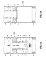
- FIG. 1A illustrates one embodiment of the present invention in cross sectional view with open flow
- FIG. 1B illustrates one embodiment of the present invention in cross sectional view with closed flow
- FIG. 2A illustraterates one embodiment of the present invention in cross sectional view with open flow
- FIG. 2B illustraterates one embodiment of the present invention in cross sectional view with closed flow
- FIG. 3A illustraterates one embodiment of the present invention in cross sectional view with fluid flow blocked
- FIG. 3B illustraterates one embodiment of the present invention in cross sectional view with upward fluid flow
- FIG. 4A illustrates one embodiment of the present invention in cross sectional view with open flow
- FIG. 4B illustrates one embodiment of the present invention in cross sectional view with closed flow
- FIG. 5A illustrates one embodiment of the present invention in cross sectional view with open flow
- FIG. 5B illustraterates one embodiment of the present invention in cross sectional view with closed flow.
- FIG. 6 illustrates one embodiment of the present invention in cross sectional view with open flow
- FIG. 7 illustrates one embodiment of the present invention in cross sectional view with closed flow by weight of tube
- FIG. 8 illustrates one embodiment of the present invention in cross sectional view with open flow with two tubulars with double seal pistons
- FIG. 9 illustrates one embodiment of the present invention in cross sectional view with closed flow due to severance of a production tube
- FIG. 10 illustrates one embodiment of the present invention in cross sectional view with fluid flow in open valve position with two tubulars and a sealing valve.
- FIG. 11 illustrates a cross sectional view of another embodiment of the invention in an open position.
- FIG. 12 illustrates a cross sectional view of another embodiment of the invention in a closed position.
- control parts might be miniaturized and placed within the inventive valve body itself.
- inventive valve may be reopened by reversing the fluid flow and pressure in production tubing, thereby preventing actual removal of the inventive valve and allowing the inventive valve to be reused.
- the internal control valve, and all component parts are preferably composed of materials as used in normal drilling operations for drilling, drill strings, and/or well bores.
- FIG. 1A illustrates a cross sectional view of one embodiment of the present inventive valve 1000 in open position.
- FIG. 1B illustrates a cross sectional view of one embodiment of the present inventive valve 1000 in closed position.
- the internal control valve 12 activates to close when the upward rate of fluid flow 4 exceeds a predetermined rate. This rate may vary depending on wellbore size, flow rate and other factors and should be determined in advance of application of the present inventive device.
- the present inventive device in all embodiments, may be comprised of various sized, shapes and weights for component parts so as to achieve desired, and predetermined flow rates with fluid flow applications.
- the valve closure of the present inventive valve 1000 is governed, in part by the weight (and port opening 3 ), of the sliding piston 2 .
- Sliding piston 2 is preferably designed so that when fluid flow 4 is at a normal predetermined level.
- the weight of sliding piston 2 can be of sufficient mass to be in the open position during normal levels. It should be noted that various predetermined flow rates can be established and utilized in several applications of the present invention.
- Sliding piston 2 is preferably designed to fit within the upper sealing surface 10 and between the production tubing 14 and 16 .
- Sliding piston 2 can also preferably be constructed with multiple flow port opening(s) 3 .
- the flow ports or openings 3 can be constructed of varying sizes and diameters based upon the pre-established flow rate parameters.
- the internal control valve 12 can be attached to the production tubing in the manner known in the art for such attachments with production tubing to allow for the flow, or stoppage of flow of fluids through the internal control valve. It is for this reason that the present inventive device can be constructed in variable sizes, and weights so as to accommodate various sizes, tolerances, and requirements of drill string utilized in the industry.
- the internal control valve 12 activates to close when the upward rate of fluid flow 4 exceeds the predetermined rate and the valve closure is governed in part by the weight of the sliding piston 2 .
- the present invention it is possible to lower the effective weight of the sliding piston 2 by including a hollow flotation chamber with the sealing base 7 . It should be noted that various predetermined flow rates can be established and utilized in several applications of the present invention. It should also be noted, that the present invention may be constructed so as to tolerate the corrosive effects of many types of fluids that may flow through the present inventive device.
- the internal control valve 12 is preferably located between segments of production tubing 14 and 16 , and preferably below the sea floor, although in several embodiments of the present invention, it can be located below the surface of a ground well or at another location.
- the internal control valve 12 preferably contains a downward facing upper sealing surface 10 , which is internal and part of the valve wall 1 .
- the valve wall 1 in this embodiment, contains, and is located adjacent to, a sliding piston 2 , having side ports 3 , through which hydrocarbon can flow upward 4 , or downward 5 , a sliding piston 2 having a sealing base 7 , having a lower and upward facing sealing surface 8 , and a piston flange stop 6 which limits the downward movement of the sliding piston 2 .
- the internal control valve 12 is preferably located between segments of production tubing 14 and 16 preferably below the sea floor.
- the internal control valve 12 preferably contains an upper sealing surface 10 which is internal and part of the valve wall 1 .
- the valve wall 1 in this embodiment is located adjacent to a sliding piston 2 , but not in mechanical communications with valve wall 1 .
- the sliding piston 2 has side ports 3 , through which hydrocarbon can flow upward flow 4 , or downward 5 , a sliding piston sealing base 8 , having a sealing surface 9 , and a piston flange stop 6 which limits the downward movement of the sliding piston 2 .
- a sliding piston sealing base 8 having a sealing surface 9
- a piston flange stop 6 which limits the downward movement of the sliding piston 2 .
- the fluid flow through internal control valve 12 can take place automatically, but when the lifting power of the upward rate of flow of hydrocarbon flow 4 exceed a calculated and established upward flow rate, and thereby causes the sealing base 7 to move upward, whereby the surface 8 of the sealing base 7 engages the sealing surface 10 inside the sliding piston 2 and thereby closes the valve to any upward flow 4 of hydrocarbons.
- the rate of the flow can be varied without removing the valve from the borehole. Under extreme circumstance (including partial penetration of the production tubing) the closing of said internal control valve 12 could be achieved by the operator severing the production tubing 14 above the mud line.
- the opening and closing ability of the flow 4 is also affected by the size of the piston port openings 3 and the weight of the sliding piston 2 .
- the factors are easily variable; in particular, the weight within the sliding piston 2 (such as by ball bearings dropped down the annulus of the production tubing). Such weights could be removed by techniques currently known in the art to accommodate various pressure applications and parameters.
- closing the internal control valve 12 takes place automatically when the lifting power of the upward rate of flow of hydrocarbon flow 4 exceeds a calculated and established upward flow rate, and thereby causes the sliding piston 2 to move upward, whereby the upward facing sealing surface 8 of the sliding piston sealing base 7 engages the downward facing sealing surface 10 inside the internal control valve 12 and thereby closes the internal control valve 12 to any upward flow 28 of hydrocarbons.
- the normal rate of flow can be varied without removing the valve from the borehole, by using a flow meter and a normal ball valve inserted between joints of the production or collection tubing on the rig floor, as is known in the art. Under some extreme circumstance (including partial penetration of the production tubing) the closing of said internal control valve 12 could be achieved by the operator severing the production tubing 14 above the sea floor (mud line).
- FIG. 2A illustrates another embodiment of the invention 1010 with an external control valve mechanism 30 with open flow.
- FIG. 2B illustrates another embodiment of the invention 1010 with an external control valve mechanism 30 with closed flow.
- the control valve mechanism 30 within the riser 34 activates when the hydrostatic pressure surrounding the riser 34 and above the sea floor (or in some embodiments surface of a ground well) 48 , infiltrates the control tubular 32 adjacent to the production tubing 35 , as when the tubular 32 is compromised by penetration or severance.
- FIG. 2B illustrates another embodiment of the invention 1010 with an external control valve mechanism 30 with open flow.
- FIG. 2B illustrates another embodiment of the invention 1010 with an external control valve mechanism 30 with closed flow.
- the control valve mechanism 30 within the riser 34 activates when the hydrostatic pressure surrounding the riser 34 and above the sea floor (or in some embodiments surface of a ground well) 48 , infiltrates the control tubular 32 adjacent to the production tubing 35 , as when the tubular 32 is compromised
- the resulting exposure of the pressure chamber 52 and the sliding piston 36 , in the valve activating mechanism 30 , to the immense hydrostatic pressure of the invading seawater will cause the teeth 38 of the sliding piston 36 to rise while engaging the teeth 40 of the ratchet wheel 45 which is connected to the rotating ball 43 in the ball valve 42 .
- the ball 43 will rotate within the socket 44 and thereby close and prevent the upward flow 46 of well hydrocarbons.
- the ratcheting of the ball valve 42 is in a fashion known in the art.
- the ball 43 can rotate to open and restore the upward hydrocarbon flow 46 , and hydrocarbon flow can resume.
- the piston w/pawl 36 and ball valve 42 can be of varying geometrical and solid shapes as would be known in the art to form a sealing mechanism.
- a hydrostatic or pneumatic fluid line 54 could be attached to the control valve mechanism 30 by which fluid could be pumped into the pressure chamber 52 .
- pressure in the pressure chamber 52 can be controlled by an external user causing the piston 36 to be actuated by which the ratcheted teeth 40 could be raised or lowered causing the ball valve 42 to engage or disengage the socket 44 .
- the raising, or lowering of the ball valve 42 would be actuated by decreases or increases in fluid pressure in the pressure chamber 52 .
- increasing pressure could cause the increased fluid to push up or lower the piston 36 .
- valve aspect of the present invention can be controlled externally, from the exposure to hydrostatic pressure existing at, or near, the seabed floor, automatically, when the riser and pneumatic fluid line are penetrated or severed. It is also envisioned that the external control parts could be miniaturized and contained within the invention 1010 . In one such embodiment of the present invention, it is envisioned that a hydrostatic or pneumatic fluid line 54 could be attached to the control valve activating assembly mechanism 30 by which fluid could be pumped into the pressure tube or chamber 52 .
- pressure in the pressure chamber 52 can be controlled from the surface causing the piston 36 to be actuated by which its ratcheted teeth 40 could be raised or lowered causing the ball valve 42 to engage or disengage the socket 44 .
- Such actuation of the piston 36 would be enabled in the same manner as actuations of piston through fluid lines as is known in the art.
- the raising, or lowering of the ball valve 42 would be actuated by decreases or increases in fluid pressure in the pressure chamber 52 .
- valve aspect of the present invention can be controlled externally by pressure increase from the surface, or automatically by hydrostatic pressures when the pneumatic fluid line tubular 32 is penetrated or severed, and whereby the interior of the line and the pressure chamber 52 are exposed to the high hydrostatic pressure surrounding the production tubing below sea level and above the sea floor.
- external control parts could be miniaturized and contained within the valve body.
- FIG. 3A illustrates another embodiment of the present invention 1020 in partial cross-sectional view in open flow state.
- FIG. 3B illustrates another embodiment of the present invention 1020 in partial cross-sectional view in closed flow state.
- the invention is in closed state, in which the valve 70 is activated by the depressing weight of production tubing 60 a above the valve 70 when production tubing 60 a above the valve 70 is severed or broken and the valve head 74 is engaged with the socket 76 .
- Valve stop upper valve 71 is located above the valve head 74 .
- the floor 73 is also illustrated in this embodiment.
- the valve is open when supported by the overlying production tubing and is closed and sealed when supported, at least, by the underlying production tubing.
- the valve can be activated by a piston or a probe.
- the present invention is a safe and quick shut in mechanism.
- Fluid 72 usually flows upward through the valve 70 on the path indicated. FIG. 3A .
- the production tubing 60 a is supported and attached to additional production tubing units above it when the well is flowing.
- weight of the higher production tubing 60 a will push downward on the valve 70 causing the valve head 74 to drop and to engage with socket 76 therein preventing the upward flow of additional fluids 72 .
- other valve configurations such as a ratchet and pawl can be utilized in the present invention instead of a plunger type valve as illustrated in FIGS. 3A and 3B .
- the production tubing 60 a is lifted in an upward fashion, thereby lifting the valve head 74 and removing it from the socket 76 .
- the lifting can be done in a manner known in the art for lifting production tubing.
- an external and vertical tongue and groove, or similar mechanism as used in the art, between the upper valve 71 and the lower valve unit, and whose purpose would be to keep the two parts of the valve from rotating separately.
- tongue and groove can mean a joint formed by inserting part of one surface material into a recessed area of a second surface. This joint design offers excellent stress resistance.
- the tongue can move within the groove, but not rotate about the groove. This would mean that when the upper valve 71 is rotated then valve 70 would rotate in the same manner.
- FIG. 4A shows another embodiment of the present invention in cross sectional view in open format.
- FIG. 4B shows another embodiment of the present invention in cross sectional view in closed format.
- the valve 1040 can stay closed and sealed after overlying support is reestablished and the valve 1040 is drawn to the surface. It thereby eliminates any necessity to “kill the well flow” (by heavy mud injection) in order to pull the valve and replace it.
- the valve 1040 can be reopened by reversing the fluid flow, temporarily to downward from upward.
- fluid 201 usually flows upward through the lower valve assembly 202 that is slideably attached to the upper valve 203 .
- the upper valve 203 is normally attached to the production tubing 204 , and the hydrocarbon fluid 201 usually flows along the path indicated. See FIG. 4A .
- the upper valve 203 is supported by many segments of production tubing 204 between it and the surface.
- the higher production tubing 204 is severed, it is envisioned in the present invention that the tremendous weight of the remaining and higher production tubing 204 , attached to, and above, the upper valve 203 , will push downward on the upper valve 203 .
- the upper valve 203 will then descend, thereby causing the downward pointing valve head probe 205 to engage with and depress the trigger unit 206 and its attached upper cam 207 .
- the attached upper cam 207 forces sideways the sliding piston roller 208 and its attached sliding piston pin 209 which is connected to a shear 210 .
- the sideways motion of the sliding piston roller 208 and the sliding piston pin 209 thereby removes the shear 210 from the shear notch 211 in the sliding piston 212 .
- the valve mainspring 213 and the upward flow of fluid 214 below the sliding piston base 217 force the upward facing surfaces 215 and 216 of the sliding piston sealing base 217 to engage in a sealing manner with the downward facing sealing surfaces 218 and 219 of the internal valve wall assembly 202 and whereby the upward flow of fluid 201 and 214 is terminated.
- fluid 201 usually flows upward through the lower valve assembly 202 that is slidably attached to the valve 203 .
- the valve 203 is normally attached to the production tubing 204 , and the fluid 201 usually flows along the path indicated. See FIG. 4A .
- the valve 203 is normally attached and supported by segments of production tubing 204 above it.
- valve head assembly 202 in the event that the higher production tubing 204 is severed, it is envisioned, in the present invention that the tremendous weight of the remaining and higher production tubing 204 , attached to and above the valve head assembly 202 , will push downward on the valve head assembly 202 . Valve head assembly 202 will then descend, thereby causing the downward pointing valve head probe 205 to engage with and depress the trigger unit 206 and its attached upper cam 207 . At this point, the attached upper cam 207 forces sideways the sliding piston roller 208 and its attached sliding piston pin 209 which it is connected to. The sideways motion of the sliding roller pin 208 thereby removing the shear 210 from the shear notch 211 in the sliding piston 212 .
- valve mainspring 213 and the upward flow of fluid 214 below the valve assembly 202 force the upward facing surfaces 215 and 216 of the sliding piston sealing base 217 to engage in a sealing manner with the downward facing sealing surfaces 218 and 219 of the internal valve 203 and whereby the upward flow of fluid 201 and 214 is terminated.
- one benefit of one embodiment of the present invention is that when the valve has been closed because of severance of the production tubing, if desirable it can be opened in place after reconnection of the production tubing by reversing the flow (as described above). If it is necessary to retrieve the valve to the surface, and the flow is not reversed, the valve will remain closed while the valve clears the rig floor.
- a closed system can be maintained by placing a standard ball valve (open) below the described inventive valve before the inventive valve is initially lowered in the borehole.
- this standard ball valve clears the rig floor, it can be closed manually.
- the inventive valve can be replaced without any danger of exposure to upward fluid flow through the production tubing and the standard ball valve.
- the inventive valve can also be tested in place in the borehole without and danger of exposure or destruction.
- FIG. 5A shows one embodiment of the present invention in partial cross-sectional view in open flow.
- FIG. 5B shows one embodiment of the present invention in partial cross-sectional view in closed flow.
- the valve 300 is activated to close by a weighted assembly 302 positioned above the valve 300 when the line or cable or support mechanism 304 supporting the weighted assembly 302 is severed or broken.
- the line or cable or support mechanism 304 can be any supportive mechanism as is known in the art.
- Fluid 306 usually flows through the valve 300 along the upward path as shown.
- a weighted assembly 302 is supported by a line, cable or other support mechanism 304 , attached to the production tubing 308 or on the rig floor.
- the support mechanism 304 is severed or broken, it is envisioned, in the present invention that the weighted assembly 302 will move downward, thereby causing the teeth 310 of the pawl 312 .
- This movement in the weighted assembly 302 causes it to engage with the teeth of the ratchet 314 thereby rotating the ball in the socket of the ball valve 316 and preventing upward flow of fluids 306 .
- the weighted assembly 302 In order to open the valve of this embodiment, the weighted assembly 302 must be lifted in an upward fashion and reattached to its original or an additional support unit of the production tubing 308 or rig floor.
- the valve is open when supported by the overlying production tubing and is closed and sealed when supported, at least, by the underlying production tubing.
- the valve can be activated by a piston or a probe.
- the present invention is a safe and quick shut in mechanism. This embodiment the vector is changed from vertical to rotational.
- FIG. 6 illustrates one embodiment of the present invention in cross sectional view with open fluid flow.
- FIG. 6 illustrates the present invention 1000 as applied with a valve comprising one tubular 1045 and a piston 1030 (with a piston head) which is activated to close by the lowering (whether controlled or uncontrolled) of a supported probe 1020 substantially in the middle of the invention 1000 .
- the present inventive device 1000 may be encased in an attached tubular 1045 .
- Attached tubular 1045 is of the kind normally used in the art for sub sea oil exploration.
- production tubing 1005 is a mechanical attachment with attached tubular 45 in a manner as known in the art. As illustrated, production tubing 1005 is preferably on the top side of attached tubular 1045 in many embodiments. Production tubing 1005 is of the type typically used in the art.
- valve 1500 is preferable constructed to be inside attached tubular 45 .
- valve 1500 can be designed with a shape such that there is a smaller diameter upper portion 1510 larger diameter middle portion 1520 and piston housing 1530 . In many embodiments, the totality of the diameter of the valve 1500 will not exceed the diameter of the tubular 1045 .
- control cable 1015 is located substantially in the middle of valve 1500 and supports probe 1020 . Cable 1015 is of the kind known in the art that can support probe 1020 inside wellbore conditions. Cable 1015 may be comprised of a pliable material capable of supporting probe 1020 . In several embodiments, cable 1015 is designed to be lowered or raised throughout valve 1500 .
- Probe 1020 is constructed to allow for fluid to flow 1010 around probe 1020 with marginal impediment to the fluid flow 1010 rate.
- probe 1020 is constructed as a cylinder with a hollow interior for fluid flow 1010 through.
- probe 1020 is constructed of a material capable of withstanding pressures and the corrosive elements found in downhole drilling applications.
- the lower portion of valve 1500 is substantially comprised of the piston housing 1530 .
- Piston housing 1530 is preferably designed to house piston head 1030 and lower valve sealing surface 1035 .
- Piston 1030 is designed in several embodiments to be able to move vertically throughout piston housing 1530 .
- Piston head 1030 is preferable created to be able to be actuated into a position of closure with lower sealing surface 1035 when fluid flow rate 1010 falls below a certain threshold, production tubing 1005 is lowered or severed, and or probe 1020 is lowered onto piston head 1030 causing the weight of probe 1020 to push piston head 1030 flush with lower sealing surface 1035 .
- piston 1030 in some embodiments, maybe comprised with perforations 1025 that are distal to the main central stem 1033 .
- the position of perforations 1025 can vary.
- perforations 1025 allow fluid flow 1010 through the piston 1030 itself.
- the perforations may be designed to be of the type to allow for fluid flow in a downhole drilling application as is known in the art.
- perforations 1025 are designed to substantially align with lower valve sealing surface 1035 when piston 1030 is in a closed position therein creating a seal and preventing the further flow of fluids 1010 up through the valve 1500 and therein the production tubing 1005 as well.
- piston 1030 is constructed with a solid flat surface 1031 which has perforations 1025 distal to the main stem 1033 .
- Main stem 1033 in many embodiments has a stabilizer 1034 on the end opposite of flat surface 1031 .
- Stabilizer 1034 is preferably designed to prevent rotation of piston 1030 which could cause it to get lodged in production tubing 1040 .
- Piston 1030 is preferably constructed of materials designed to withstand oil and/or gas drilling operations.
- the present invention operates as follows: During normal operating conditions, fluid flows 1010 from the lower portion of the valve 1540 through and around piston 30 and through valve constriction 1525 which separates piston housing 1530 from middle portion 1520 . In some embodiments of the present invention, fluid flow 1010 can continue around, and in some case through probe 1020 attached by cable 1015 . Fluid then flows out of upper portion 1510 and out through production tubing 1005 .
- FIG. 7 illustrates one, of many, scenarios in which probe 1020 can be lowered onto piston head 1030 .
- a user can lower probe 1020 onto piston head 1030 by providing slack in cable 1015 .
- the slack in cable 1015 allows for the weight of probe 1020 to push on piston head 1030 (due to the mass of probe 1020 ) and push piston head 1030 into a sealing communication with lower valve sealing surface 1035 .
- fluid flow 1010 is impeded from proceeding past production tubing 1040 .
- valve 1020 are working properly to shut in production tubing in case of a breach or perforation of production tubing/drill string.
- FIGS. 6-10 there is no need for severance of a production tubing above the valve.
- the valve is open when supported by the overlying production tubing and is closed and sealed when supported, at least, by the underlying production tubing.
- the valve can be activated by a piston or a probe.
- the present invention is a safe and quick shut in mechanism.
- valve 2500 is preferable constructed to be attached to tubular 1190 , more specifically to production tube 1100 .
- valve 2500 can be designed with a shape such that there is a smaller diameter upper portion 2510 larger diameter middle portion 2520 and piston housing 2530 . In many embodiments, the totality of the diameter of the valve 2500 will not exceed the diameter of the tubular 1180 .
- control cable 1125 is located substantially in the middle of valve 2500 and supports probe 1130 . Cable 1125 is of the kind known in the art that can support probe 1130 inside wellbore conditions. Cable 1125 may be comprised of a pliable material capable of supporting probe 1130 .
- cable 1125 is designed to be lowered or raised throughout valve 2500 .
- Cable 1125 is attached to probe 1130 in a manner known in the art.
- probe 1130 is constructed to allow for fluid to flow around probe 1130 with marginal impediment to the fluid flow rate 1110 .
- probe 1130 is constructed as a cylinder with a hollow interior for fluid flow through.
- probe 1130 is constructed of a material capable of withstanding pressures and the corrosive elements found in downhole drilling applications.
- tongue 1115 is attached to the upper valve tubular 1190 and runs into unattached tubular 1180 .
- unattached tubular 1180 has an interior sealing contact with valve body 2580 .
- the lower portion of valve 2500 is substantially comprised of the piston housing 2530 .
- Piston housing 2530 is preferably designed to house piston head 1030 and lower valve sealing surface 1035 .
- Piston 1135 is designed in several embodiments to be able to move vertically throughout piston housing. Piston head 1135 is preferable created to be able to be actuated into a position of closure with lower sealing surface 1150 when fluid flow rate 1110 falls below a certain threshold, production tubing 1100 is severed, and or probe 1130 is lowered onto piston head 1135 causing the weight of probe 1130 to push piston head 1135 flush with lower sealing surface 1150 .
- piston 1135 in some embodiments, maybe comprised with perforations 1136 that are distal to the main central stem 1137 .
- perforations 1136 allow fluid flow 1110 through the piston 1135 itself.
- the perforations maybe designed to be of the type to allow for fluid flow in a downhole drilling application as is known in the art.
- perforations 1136 are designed to substantially align with lower valve sealing surface 1150 when piston 1135 is in a closed position therein creating a seal and preventing the further flow of fluids 1110 up through the valve 2500 and therein the production tubing 1100 as well.
- piston 1135 is constructed with a solid flat surface 1140 which has perforations 136 distal to the main stem 1137 .
- Main stem 1137 in many embodiments has a stabilizer 1138 on the end opposite of flat surface 1140 .
- Stabilizer 1138 is preferably designed to prevent rotation of piston 1135 which could cause it to get lodged in production tubing 1160 .
- Piston 1135 is preferably constructed of materials designed to withstand oil and/or gas drilling operations.
- the present invention operates as follows. During normal operating conditions, fluid flows 1110 from the lower portion of the valve 2540 through and around piston 1136 and through valve constriction 2525 which separates piston housing 2530 from middle portion 2520 . In some embodiments of the present invention, fluid flow 1110 can continue around, and in some case through probe 1130 attached by cable 1125 . Fluid then flows out of upper portion 2510 and out through production tubing 100 .
- FIG. 9 illustrates one scenario in which probe 1130 is held relatively stationary in view of piston head 1135 .
- the sealing contact 1175 is broken between the unattached tubular 1180 and the valve body 2580 .
- valve body 2580 will fall into unattached tubular 1180 pushing valve body 2580 to compress piston housing 1170 and force piston 135 to come into sealing contact with valve sealing part 1150 . In this manner, no fluid flow 1165 can proceed past production tube 1160 therein shutting of the valve 2500 .
- FIG. 10 illustrates one scenario in which probe 1130 is lowered onto piston head 1135 .
- a user can lower probe 1130 onto piston head 1135 by providing slack in cable 1125 .
- the slack in cable 1125 allows for probe 1130 to push on piston head 1135 (due to the mass of probe 1130 ) and push piston head 1135 into a sealing communication with lower valve sealing surface 1150 .
- fluid flow 1110 is impeded from proceeding past production tubing 1160 . It is by this manual method of providing slack to cable 1125 that a user can test to see if piston head 1135 and valve 2500 are working properly to shut in production tubing in case of a breach or perforation of production tubing/drill string.
- valves of the present invention can always have the option of deciding to sever at the mud line, any and all, tubing or supporting lines necessary to close any of these valves. This is fundamental for all valves and embodiments associated with this invention. It is envisioned that in one or more of the embodiments of the present invention there can be multiple valves as described herein for increased safety and efficacy.
- FIG. 11 shows one embodiment of the invention with production tubing 1005 and 1040 .
- production tubing 1040 is attached to the valve via threaded end plug 2035 .
- threaded end plug 2035 On top of threaded end plug 2035 is unattached valve part sealing 1035 .
- Attached valve 1030 is located above the unattached valve part sealing 1035 is in the open position and has perforations 1025 .
- packer 2020 and packer activating sliding weight cylinder 2030 Attached to packer 2020 is attached to the attached part of the valve 2047 .
- extra tubular 2040 As shown, in this embodiment, the fluid 1010 is flowing upward and through the valve.
- FIG. 12 shows one embodiment of the invention with production tubing 1005 and 1040 .
- production tubing 1040 is attached to the valve via threaded end plug 2035 .
- threaded end plug 2035 On top of threaded end plug 2035 is unattached valve part sealing 1035 .
- Attached valve 1030 is located adjacent the unattached valve part sealing 1035 is in the closed position and has perforations 1025 .
- packer 2020 and packer activating sliding weight cylinder 2030 Attached to packer 2020 is attached to the attached part of the valve 2047 .
- extra tubular 2040 As shown, in this embodiment, the fluid 1010 is closed and not flowing through the valve.
- 2020 , 2030 , 2035 can be constructed of one piece of material in some embodiments.
- valves of the present invention can always have the option of deciding to sever at the mud line, any and all, tubing or supporting lines necessary to close any of these valves. This is fundamental for all valves and embodiments associated with this invention. It is envisioned that in one or more of the embodiments of the present invention there can be multiple valves as described herein for increased safety and efficacy.
Landscapes
- Life Sciences & Earth Sciences (AREA)
- Engineering & Computer Science (AREA)
- Geology (AREA)
- Mining & Mineral Resources (AREA)
- Physics & Mathematics (AREA)
- Environmental & Geological Engineering (AREA)
- Fluid Mechanics (AREA)
- General Life Sciences & Earth Sciences (AREA)
- Geochemistry & Mineralogy (AREA)
- Lift Valve (AREA)
Abstract
Description
Claims (4)
Priority Applications (1)
| Application Number | Priority Date | Filing Date | Title |
|---|---|---|---|
| US15/676,414 US9874072B2 (en) | 2013-03-15 | 2017-08-14 | Pipe valve control and method of use |
Applications Claiming Priority (3)
| Application Number | Priority Date | Filing Date | Title |
|---|---|---|---|
| US201361787184P | 2013-03-15 | 2013-03-15 | |
| US14/205,057 US20140261775A1 (en) | 2013-03-15 | 2014-03-11 | Pipe valve control and method of use |
| US15/676,414 US9874072B2 (en) | 2013-03-15 | 2017-08-14 | Pipe valve control and method of use |
Related Parent Applications (1)
| Application Number | Title | Priority Date | Filing Date |
|---|---|---|---|
| US14/205,057 Continuation-In-Part US20140261775A1 (en) | 2013-03-15 | 2014-03-11 | Pipe valve control and method of use |
Publications (2)
| Publication Number | Publication Date |
|---|---|
| US20170342803A1 US20170342803A1 (en) | 2017-11-30 |
| US9874072B2 true US9874072B2 (en) | 2018-01-23 |
Family
ID=60417633
Family Applications (1)
| Application Number | Title | Priority Date | Filing Date |
|---|---|---|---|
| US15/676,414 Active US9874072B2 (en) | 2013-03-15 | 2017-08-14 | Pipe valve control and method of use |
Country Status (1)
| Country | Link |
|---|---|
| US (1) | US9874072B2 (en) |
Cited By (1)
| Publication number | Priority date | Publication date | Assignee | Title |
|---|---|---|---|---|
| US20230175352A1 (en) * | 2019-12-05 | 2023-06-08 | Halliburton Energy Services, Inc. | Ingress-barrier assembly for use with pressure-operated downhole equipment |
Families Citing this family (2)
| Publication number | Priority date | Publication date | Assignee | Title |
|---|---|---|---|---|
| AU2015400341B2 (en) * | 2015-06-29 | 2019-04-11 | Halliburton Energy Services, Inc. | Rotary sleeve to control annular flow |
| US20250382854A1 (en) * | 2024-06-17 | 2025-12-18 | Schlumberger Technology Corporation | Method to mitigate wellbore instabilities |
Citations (41)
| Publication number | Priority date | Publication date | Assignee | Title |
|---|---|---|---|---|
| US1706072A (en) | 1926-10-06 | 1929-03-19 | Walter N Rieger | Circulation shut-off device |
| US2236137A (en) * | 1938-02-25 | 1941-03-25 | William F Grisham | Flow valve |
| US2308668A (en) * | 1940-08-28 | 1943-01-19 | Dow Chemical Co | Apparatus for treating wells |
| US2563155A (en) | 1946-01-12 | 1951-08-07 | Signal Oil & Gas Co | Blowout preventer and tubing head for pumping wells |
| US3319923A (en) | 1962-04-20 | 1967-05-16 | Shell Oil Co | Electro-hydraulic blowout preventer |
| US3332497A (en) | 1964-11-12 | 1967-07-25 | Jr John S Page | Tubing and annulus pressure responsive and retrievable valve |
| US3351133A (en) | 1965-06-14 | 1967-11-07 | Baker Oil Tools Inc | Tubing weight-controlled safety valve apparatus |
| US3411585A (en) | 1966-04-28 | 1968-11-19 | John S. Page Jr. | Surface control of sub-surface well valving using flow passing tubing link |
| US3652824A (en) | 1968-12-13 | 1972-03-28 | Osaka Transformer Co Ltd | Dc arc welder |
| US4202368A (en) | 1978-03-13 | 1980-05-13 | Baker Cac, Inc. | Safety valve or blowout preventer for use in a fluid transmission conduit |
| US4460149A (en) | 1980-06-05 | 1984-07-17 | Nl Industries, Inc. | Annular blowout preventer with upper and lower spherical sealing surfaces |
| US4478279A (en) | 1982-10-12 | 1984-10-23 | Hydril Company | Retrievable inside blowout preventer valve apparatus |
| US4537353A (en) | 1983-02-28 | 1985-08-27 | Eaton Corporation | Low-power acoustic injector drive circuit with enhanced turn-on |
| US4537383A (en) | 1984-10-02 | 1985-08-27 | Otis Engineering Corporation | Valve |
| US5012854A (en) | 1987-03-31 | 1991-05-07 | Baroid Technology, Inc. | Pressure release valve for a subsea blowout preventer |
| US5074518A (en) | 1990-11-02 | 1991-12-24 | Hydratech | Proportional annular B.O.P. controller |
| US5199683A (en) | 1992-06-09 | 1993-04-06 | Baroid Technology, Inc. | Blowout preventer opening mechanism |
| EP0634560A1 (en) | 1993-07-12 | 1995-01-18 | Cooper Cameron Corporation | Downhole safety valve |
| US5735502A (en) | 1996-12-18 | 1998-04-07 | Varco Shaffer, Inc. | BOP with partially equalized ram shafts |
| EP0943781A2 (en) | 1998-03-19 | 1999-09-22 | Halliburton Energy Services, Inc. | Sub-sea test tree |
| US6129152A (en) | 1998-04-29 | 2000-10-10 | Alpine Oil Services Inc. | Rotating bop and method |
| US6257268B1 (en) | 1999-12-01 | 2001-07-10 | Gilmore Valve Company | Pressure biased shuttle valve |
| US6321846B1 (en) | 2000-02-24 | 2001-11-27 | Schlumberger Technology Corp. | Sealing device for use in subsea wells |
| US6644411B2 (en) | 2001-04-18 | 2003-11-11 | Kvaerner Oilfield Products, Inc. | Tubing hanger with flapper valve |
| US6907898B2 (en) | 2002-07-10 | 2005-06-21 | Travis H. White | Fluid shutoff apparatus |
| EP1639226A2 (en) | 2003-06-10 | 2006-03-29 | Dril-Quip, Inc. | Wellhead assembly with pressure actuated seal assembly and running tool |
| US7062960B2 (en) | 2001-06-22 | 2006-06-20 | Cooper Cameron Corporation | Blow out preventer testing apparatus |
| US7121295B2 (en) | 2003-10-21 | 2006-10-17 | Varco I/P, Inc. | Internal blow out preventer ball and seat |
| US7121344B2 (en) | 2003-01-10 | 2006-10-17 | Vetco Gray Inc. | Plug installation system for deep water subsea wells |
| US7234527B2 (en) | 2002-07-03 | 2007-06-26 | Halliburton Energy Services, Inc. | System and method for fail-safe disconnect from a subsea well |
| US7287544B2 (en) | 2003-10-21 | 2007-10-30 | Varco I/P, Inc. | Triple valve blow out preventer |
| US7424917B2 (en) | 2005-03-23 | 2008-09-16 | Varco I/P, Inc. | Subsea pressure compensation system |
| US7464765B2 (en) | 2005-08-24 | 2008-12-16 | National-Oilwell Dht, L.P. | Inner guide seal assembly and method for a ram type BOP system |
| US7673677B2 (en) | 2007-08-13 | 2010-03-09 | Baker Hughes Incorporated | Reusable ball seat having ball support member |
| US8047295B2 (en) | 2007-04-24 | 2011-11-01 | Fmc Technologies, Inc. | Lightweight device for remote subsea wireline intervention |
| US20110299930A1 (en) | 2010-06-04 | 2011-12-08 | Messina Frank D | Subsea oil leak stabilization system and method |
| US20120000645A1 (en) | 2010-07-04 | 2012-01-05 | Wolfhart Willimczik | Flow controller, particularly blowout preventer (BOP) and smart pipe plug (SPP) |
| US8443897B2 (en) | 2011-01-06 | 2013-05-21 | Halliburton Energy Services, Inc. | Subsea safety system having a protective frangible liner and method of operating same |
| US8567490B2 (en) | 2009-06-19 | 2013-10-29 | National Oilwell Varco, L.P. | Shear seal blowout preventer |
| US8978698B2 (en) | 2010-07-01 | 2015-03-17 | National Oilwell Varco, L.P. | Blowout preventer monitoring system and method of using same |
| US9091136B2 (en) | 2011-06-02 | 2015-07-28 | Schlumberger Technology Corporation | Subsea safety valve system |
-
2017
- 2017-08-14 US US15/676,414 patent/US9874072B2/en active Active
Patent Citations (43)
| Publication number | Priority date | Publication date | Assignee | Title |
|---|---|---|---|---|
| US1706072A (en) | 1926-10-06 | 1929-03-19 | Walter N Rieger | Circulation shut-off device |
| US2236137A (en) * | 1938-02-25 | 1941-03-25 | William F Grisham | Flow valve |
| US2308668A (en) * | 1940-08-28 | 1943-01-19 | Dow Chemical Co | Apparatus for treating wells |
| US2563155A (en) | 1946-01-12 | 1951-08-07 | Signal Oil & Gas Co | Blowout preventer and tubing head for pumping wells |
| US3319923A (en) | 1962-04-20 | 1967-05-16 | Shell Oil Co | Electro-hydraulic blowout preventer |
| US3332497A (en) | 1964-11-12 | 1967-07-25 | Jr John S Page | Tubing and annulus pressure responsive and retrievable valve |
| US3351133A (en) | 1965-06-14 | 1967-11-07 | Baker Oil Tools Inc | Tubing weight-controlled safety valve apparatus |
| US3411585A (en) | 1966-04-28 | 1968-11-19 | John S. Page Jr. | Surface control of sub-surface well valving using flow passing tubing link |
| US3652824A (en) | 1968-12-13 | 1972-03-28 | Osaka Transformer Co Ltd | Dc arc welder |
| US4202368A (en) | 1978-03-13 | 1980-05-13 | Baker Cac, Inc. | Safety valve or blowout preventer for use in a fluid transmission conduit |
| US4460149A (en) | 1980-06-05 | 1984-07-17 | Nl Industries, Inc. | Annular blowout preventer with upper and lower spherical sealing surfaces |
| US4478279A (en) | 1982-10-12 | 1984-10-23 | Hydril Company | Retrievable inside blowout preventer valve apparatus |
| US4537353A (en) | 1983-02-28 | 1985-08-27 | Eaton Corporation | Low-power acoustic injector drive circuit with enhanced turn-on |
| US4537383A (en) | 1984-10-02 | 1985-08-27 | Otis Engineering Corporation | Valve |
| US5012854A (en) | 1987-03-31 | 1991-05-07 | Baroid Technology, Inc. | Pressure release valve for a subsea blowout preventer |
| US5074518A (en) | 1990-11-02 | 1991-12-24 | Hydratech | Proportional annular B.O.P. controller |
| US5199683A (en) | 1992-06-09 | 1993-04-06 | Baroid Technology, Inc. | Blowout preventer opening mechanism |
| EP0634560A1 (en) | 1993-07-12 | 1995-01-18 | Cooper Cameron Corporation | Downhole safety valve |
| US5735502A (en) | 1996-12-18 | 1998-04-07 | Varco Shaffer, Inc. | BOP with partially equalized ram shafts |
| US6026905A (en) | 1998-03-19 | 2000-02-22 | Halliburton Energy Services, Inc. | Subsea test tree and methods of servicing a subterranean well |
| EP0943781A2 (en) | 1998-03-19 | 1999-09-22 | Halliburton Energy Services, Inc. | Sub-sea test tree |
| US6129152A (en) | 1998-04-29 | 2000-10-10 | Alpine Oil Services Inc. | Rotating bop and method |
| US6257268B1 (en) | 1999-12-01 | 2001-07-10 | Gilmore Valve Company | Pressure biased shuttle valve |
| US6321846B1 (en) | 2000-02-24 | 2001-11-27 | Schlumberger Technology Corp. | Sealing device for use in subsea wells |
| US6644411B2 (en) | 2001-04-18 | 2003-11-11 | Kvaerner Oilfield Products, Inc. | Tubing hanger with flapper valve |
| US7062960B2 (en) | 2001-06-22 | 2006-06-20 | Cooper Cameron Corporation | Blow out preventer testing apparatus |
| US7234527B2 (en) | 2002-07-03 | 2007-06-26 | Halliburton Energy Services, Inc. | System and method for fail-safe disconnect from a subsea well |
| US6907898B2 (en) | 2002-07-10 | 2005-06-21 | Travis H. White | Fluid shutoff apparatus |
| US7121344B2 (en) | 2003-01-10 | 2006-10-17 | Vetco Gray Inc. | Plug installation system for deep water subsea wells |
| EP1639226A2 (en) | 2003-06-10 | 2006-03-29 | Dril-Quip, Inc. | Wellhead assembly with pressure actuated seal assembly and running tool |
| US7287544B2 (en) | 2003-10-21 | 2007-10-30 | Varco I/P, Inc. | Triple valve blow out preventer |
| US7121295B2 (en) | 2003-10-21 | 2006-10-17 | Varco I/P, Inc. | Internal blow out preventer ball and seat |
| US7424917B2 (en) | 2005-03-23 | 2008-09-16 | Varco I/P, Inc. | Subsea pressure compensation system |
| US7464765B2 (en) | 2005-08-24 | 2008-12-16 | National-Oilwell Dht, L.P. | Inner guide seal assembly and method for a ram type BOP system |
| US8047295B2 (en) | 2007-04-24 | 2011-11-01 | Fmc Technologies, Inc. | Lightweight device for remote subsea wireline intervention |
| US7673677B2 (en) | 2007-08-13 | 2010-03-09 | Baker Hughes Incorporated | Reusable ball seat having ball support member |
| US8567490B2 (en) | 2009-06-19 | 2013-10-29 | National Oilwell Varco, L.P. | Shear seal blowout preventer |
| US8770274B2 (en) | 2009-06-19 | 2014-07-08 | National Oilwell Varco, L.P. | Shear seal blowout preventer |
| US20110299930A1 (en) | 2010-06-04 | 2011-12-08 | Messina Frank D | Subsea oil leak stabilization system and method |
| US8978698B2 (en) | 2010-07-01 | 2015-03-17 | National Oilwell Varco, L.P. | Blowout preventer monitoring system and method of using same |
| US20120000645A1 (en) | 2010-07-04 | 2012-01-05 | Wolfhart Willimczik | Flow controller, particularly blowout preventer (BOP) and smart pipe plug (SPP) |
| US8443897B2 (en) | 2011-01-06 | 2013-05-21 | Halliburton Energy Services, Inc. | Subsea safety system having a protective frangible liner and method of operating same |
| US9091136B2 (en) | 2011-06-02 | 2015-07-28 | Schlumberger Technology Corporation | Subsea safety valve system |
Cited By (2)
| Publication number | Priority date | Publication date | Assignee | Title |
|---|---|---|---|---|
| US20230175352A1 (en) * | 2019-12-05 | 2023-06-08 | Halliburton Energy Services, Inc. | Ingress-barrier assembly for use with pressure-operated downhole equipment |
| US11939838B2 (en) * | 2019-12-05 | 2024-03-26 | Halliburton Energy Services, Inc. | Ingress-barrier assembly for use with pressure-operated downhole equipment |
Also Published As
| Publication number | Publication date |
|---|---|
| US20170342803A1 (en) | 2017-11-30 |
Similar Documents
| Publication | Publication Date | Title |
|---|---|---|
| US11512549B2 (en) | Well surface safety valve assembly with a ball valve and back pressure valve | |
| US20190264534A1 (en) | Valve Apparatus Having Dissolvable or Frangible Flapper and Method of Using Same | |
| US7624792B2 (en) | Shear activated safety valve system | |
| CA2862986C (en) | Wiper plug elements and methods of stimulating a wellbore environment | |
| US7314091B2 (en) | Cement-through, tubing retrievable safety valve | |
| EP2699761B1 (en) | Ball valve safety plug | |
| AU2008293713A1 (en) | Interventionless multi-position frac tool | |
| USRE27464E (en) | Well tools | |
| WO2019040060A1 (en) | Balance line safety valve | |
| WO2013089730A1 (en) | Dual closure system for well system | |
| US9874072B2 (en) | Pipe valve control and method of use | |
| GB2628743A (en) | Single-trip deployment and isolation using flapper valve | |
| US11041365B2 (en) | Annular controlled safety valve system and method | |
| US9822607B2 (en) | Control line damper for valves | |
| US20140261775A1 (en) | Pipe valve control and method of use | |
| US10077632B2 (en) | Pilot inside a ball suitable for wellbore drilling operations | |
| AU2012384917B2 (en) | Control line damper for valves | |
| GB2467475A (en) | Shear activated safety valve system |
Legal Events
| Date | Code | Title | Description |
|---|---|---|---|
| STCF | Information on status: patent grant |
Free format text: PATENTED CASE |
|
| AS | Assignment |
Owner name: ELLIOTT, VIRGINIA CLEMENT, TEXAS Free format text: ASSIGNMENT OF ASSIGNORS INTEREST;ASSIGNORS:MOTHERAL, PATRICIA CLEMENT;ELLIOTT, VIRGINIA CLEMENT;REEL/FRAME:049207/0906 Effective date: 20181212 Owner name: THORNTON, JOHN, TEXAS Free format text: ASSIGNMENT OF ASSIGNORS INTEREST;ASSIGNORS:MOTHERAL, PATRICIA CLEMENT;ELLIOTT, VIRGINIA CLEMENT;REEL/FRAME:049207/0906 Effective date: 20181212 Owner name: MOTHERAL, PATRICIA CLEMENT, TEXAS Free format text: ASSIGNMENT OF ASSIGNORS INTEREST;ASSIGNORS:MOTHERAL, PATRICIA CLEMENT;ELLIOTT, VIRGINIA CLEMENT;REEL/FRAME:049207/0906 Effective date: 20181212 Owner name: TREVINO, ESMER, TEXAS Free format text: ASSIGNMENT OF ASSIGNORS INTEREST;ASSIGNORS:MOTHERAL, PATRICIA CLEMENT;ELLIOTT, VIRGINIA CLEMENT;REEL/FRAME:049207/0906 Effective date: 20181212 |
|
| AS | Assignment |
Owner name: MOTHERAL, PATRICIA CLEMENT, TEXAS Free format text: ASSIGNMENT OF ASSIGNORS INTEREST;ASSIGNORS:MOTHERAL, PATRICIA CLEMENT;ELLIOTT, VIRGINIA CLEMENT;REEL/FRAME:048180/0775 Effective date: 20181212 Owner name: ELLIOTT, VIRGINIA CLEMENT, TEXAS Free format text: ASSIGNMENT OF ASSIGNORS INTEREST;ASSIGNORS:MOTHERAL, PATRICIA CLEMENT;ELLIOTT, VIRGINIA CLEMENT;REEL/FRAME:048180/0775 Effective date: 20181212 Owner name: TREVINO, ESMER, TEXAS Free format text: ASSIGNMENT OF ASSIGNORS INTEREST;ASSIGNORS:MOTHERAL, PATRICIA CLEMENT;ELLIOTT, VIRGINIA CLEMENT;REEL/FRAME:048180/0775 Effective date: 20181212 Owner name: THORNTON, JOHN, TEXAS Free format text: ASSIGNMENT OF ASSIGNORS INTEREST;ASSIGNORS:MOTHERAL, PATRICIA CLEMENT;ELLIOTT, VIRGINIA CLEMENT;REEL/FRAME:048180/0775 Effective date: 20181212 |
|
| MAFP | Maintenance fee payment |
Free format text: PAYMENT OF MAINTENANCE FEE, 4TH YR, SMALL ENTITY (ORIGINAL EVENT CODE: M2551); ENTITY STATUS OF PATENT OWNER: SMALL ENTITY Year of fee payment: 4 |
|
| FEPP | Fee payment procedure |
Free format text: MAINTENANCE FEE REMINDER MAILED (ORIGINAL EVENT CODE: REM.); ENTITY STATUS OF PATENT OWNER: SMALL ENTITY |