US9865986B2 - Coherent combining pulse bursts in time domain - Google Patents
Coherent combining pulse bursts in time domain Download PDFInfo
- Publication number
- US9865986B2 US9865986B2 US15/104,924 US201415104924A US9865986B2 US 9865986 B2 US9865986 B2 US 9865986B2 US 201415104924 A US201415104924 A US 201415104924A US 9865986 B2 US9865986 B2 US 9865986B2
- Authority
- US
- United States
- Prior art keywords
- pulses
- pulse
- optical
- cluster
- optical signals
- Prior art date
- Legal status (The legal status is an assumption and is not a legal conclusion. Google has not performed a legal analysis and makes no representation as to the accuracy of the status listed.)
- Active
Links
Images


Classifications
-
- H—ELECTRICITY
- H01—ELECTRIC ELEMENTS
- H01S—DEVICES USING THE PROCESS OF LIGHT AMPLIFICATION BY STIMULATED EMISSION OF RADIATION [LASER] TO AMPLIFY OR GENERATE LIGHT; DEVICES USING STIMULATED EMISSION OF ELECTROMAGNETIC RADIATION IN WAVE RANGES OTHER THAN OPTICAL
- H01S3/00—Lasers, i.e. devices using stimulated emission of electromagnetic radiation in the infrared, visible or ultraviolet wave range
- H01S3/10—Controlling the intensity, frequency, phase, polarisation or direction of the emitted radiation, e.g. switching, gating, modulating or demodulating
- H01S3/106—Controlling the intensity, frequency, phase, polarisation or direction of the emitted radiation, e.g. switching, gating, modulating or demodulating by controlling devices placed within the cavity
- H01S3/1062—Controlling the intensity, frequency, phase, polarisation or direction of the emitted radiation, e.g. switching, gating, modulating or demodulating by controlling devices placed within the cavity using a controlled passive interferometer, e.g. a Fabry-Perot etalon
-
- H—ELECTRICITY
- H01—ELECTRIC ELEMENTS
- H01S—DEVICES USING THE PROCESS OF LIGHT AMPLIFICATION BY STIMULATED EMISSION OF RADIATION [LASER] TO AMPLIFY OR GENERATE LIGHT; DEVICES USING STIMULATED EMISSION OF ELECTROMAGNETIC RADIATION IN WAVE RANGES OTHER THAN OPTICAL
- H01S3/00—Lasers, i.e. devices using stimulated emission of electromagnetic radiation in the infrared, visible or ultraviolet wave range
- H01S3/005—Optical devices external to the laser cavity, specially adapted for lasers, e.g. for homogenisation of the beam or for manipulating laser pulses, e.g. pulse shaping
-
- H—ELECTRICITY
- H01—ELECTRIC ELEMENTS
- H01S—DEVICES USING THE PROCESS OF LIGHT AMPLIFICATION BY STIMULATED EMISSION OF RADIATION [LASER] TO AMPLIFY OR GENERATE LIGHT; DEVICES USING STIMULATED EMISSION OF ELECTROMAGNETIC RADIATION IN WAVE RANGES OTHER THAN OPTICAL
- H01S3/00—Lasers, i.e. devices using stimulated emission of electromagnetic radiation in the infrared, visible or ultraviolet wave range
- H01S3/10—Controlling the intensity, frequency, phase, polarisation or direction of the emitted radiation, e.g. switching, gating, modulating or demodulating
- H01S3/13—Stabilisation of laser output parameters, e.g. frequency or amplitude
- H01S3/1307—Stabilisation of the phase
-
- H—ELECTRICITY
- H01—ELECTRIC ELEMENTS
- H01S—DEVICES USING THE PROCESS OF LIGHT AMPLIFICATION BY STIMULATED EMISSION OF RADIATION [LASER] TO AMPLIFY OR GENERATE LIGHT; DEVICES USING STIMULATED EMISSION OF ELECTROMAGNETIC RADIATION IN WAVE RANGES OTHER THAN OPTICAL
- H01S3/00—Lasers, i.e. devices using stimulated emission of electromagnetic radiation in the infrared, visible or ultraviolet wave range
- H01S3/23—Arrangements of two or more lasers not provided for in groups H01S3/02 - H01S3/22, e.g. tandem arrangements of separate active media
- H01S3/2308—Amplifier arrangements, e.g. MOPA
-
- H—ELECTRICITY
- H01—ELECTRIC ELEMENTS
- H01S—DEVICES USING THE PROCESS OF LIGHT AMPLIFICATION BY STIMULATED EMISSION OF RADIATION [LASER] TO AMPLIFY OR GENERATE LIGHT; DEVICES USING STIMULATED EMISSION OF ELECTROMAGNETIC RADIATION IN WAVE RANGES OTHER THAN OPTICAL
- H01S3/00—Lasers, i.e. devices using stimulated emission of electromagnetic radiation in the infrared, visible or ultraviolet wave range
- H01S3/23—Arrangements of two or more lasers not provided for in groups H01S3/02 - H01S3/22, e.g. tandem arrangements of separate active media
- H01S3/2383—Parallel arrangements
-
- G—PHYSICS
- G02—OPTICS
- G02B—OPTICAL ELEMENTS, SYSTEMS OR APPARATUS
- G02B27/00—Optical systems or apparatus not provided for by any of the groups G02B1/00 - G02B26/00, G02B30/00
- G02B27/10—Beam splitting or combining systems
- G02B27/1006—Beam splitting or combining systems for splitting or combining different wavelengths
Definitions
- the present disclosure relates to lasers and more specifically to coherent combining of multiple laser beams and temporal pulse stacking to increase pulse energy.
- Beam combining of multiple lasers allows overcoming power and energy limitations of each individual laser.
- Beam combining of multiple laser signals can be currently achieved using a variety of methods such as active coherent phasing, incoherent spectral combining, passive self-locked combining, or incoherent spatial addition of multiple laser beams.
- each parallel laser channel generates an identical signal and all parallel output signals are then combined with the total combined power proportional to the sum of individual powers from all N laser channels. The maximum achievable power can never exceed this total sum, as fundamentally limited by the power conservation law.
- These beam combining methods can be applied to continuous wave signals as well as pulsed signals. When these currently used methods are used to combine pulsed beams, the combined energy per each pulse can never exceed the sum of individual pulse energies from all the channels.
- a 3 m long roundtrip cavity corresponds to 100 MHz repetition rate of the periodic pulse input.
- each pulse in the input periodic signal is at about 1 mJ of energy (expected energy of ⁇ 1 ns pulse at the maximum of each parallel amplification channel)
- the average power per each amplified beam from each parallel channel is approximately 100 kW.
- a method for coherently combining pulses of a pulsed optical signal in the time domain.
- the method includes: receiving an optical input signal comprised of a periodic pulse train; splitting the input signal into two optical signals; forming at least one cluster of pulses in each of the two optical signals, where amplitude and phase of pulses in each cluster varies amongst pulses; and coherently combining the two optical signals in the time domain using a resonant cavity and thereby forming an optical output signal having a solitary pulse for each cluster of pulses, where the two optical signals are combined in a manner such that pulse energy of the solidary pulse exceeds N times highest energy of any given pulse in the cluster of pulses from the two optical signals.
- Clusters of pulses may be formed by amplitude modulating and phase modulating the two optical signals.
- the clusters of pulses in the two optical signals are formed complementary with each other in the spectral domain.
- the two optical signals may be combined using a Fabry-Perot interferometer.
- This method may be extended to coherently combine pulses from N optical signals.
- the method includes: receiving an optical input signal comprised of a periodic pulse train; splitting the input signal into N optical signals; amplitude modulating each signal in the N optical signals to form clusters of pulses in each signal, such that amplitude of pulses in each cluster varies amongst pulses; phase modulating each signal in the N optical signals, such that phase of pulses in each cluster varies amongst pulses; and coherently combining each of the phase modulated signals in the time domain using one or more resonant cavities and thereby forming an optical output signal having a solitary pulse for each cluster of pulses, where the N optical signals are combined in a manner such that pulse energy of the solidary pulse exceeds N times highest energy of any given pulse in the cluster of pulses from the N optical signals.
- each of the phase modulated signals may be amplified. Additionally, the N optical signal can be phase locked.
- the phase modulated signals are coherently combined using a plurality of Fabry-Perot interferometer cavities arranged in either a parallel cascading manner or a sequential cascading manner.
- a method for coherently combining (or stacking) pulses from a single optical signal in the time domain.
- the method includes: receiving an optical input signal comprised of a periodic pulse train; forming at least one cluster of pulses in the pulse train, where amplitude and phase of pulses in the at least one cluster varies amongst pulses; and coherently combining pulses in the at least one cluster in the time domain to form an optical signal with a solitary pulse using a resonant cavity, where the resonant cavity has an entirely reflective cavity.
- the resonant cavity may be further defined as a Gires-Tournois interferometer cavity.
- Pulse energy can be further increased through the use of N parallel channel amplification array.
- This method includes: receiving an optical input signal comprised of a periodic pulse train; amplitude modulating the optical input signal to form at least one clusters of pulses, such that amplitude of pulses in each cluster varies amongst pulses; phase modulating the optical input signal, such that phase of pulses in each cluster varies amongst pulses; splitting the optical input signal into N optical signals; amplifying each of the N optical signals; coherently combining each of the amplified optical signals into a combined signal using a beam combiner; and coherently combining pulses in the at least one cluster of pulses in the combined signal in the time domain using a resonant cavity having an entirely reflective cavity, thereby forming an optical output signal having a solitary pulse for each cluster of pulses.
- N Gires-Tournois interferometers can be arranged in a sequential cascading manner, such that the energy increase of a solitary pulse is approximately 2N.
- Gires-Tournois interferometers can be arranged in two or more sequential stages, where each stage includes N Gires-Tournois interferometers arranged in a sequential cascading manner and the Gires-Tournois interferometer in each subsequent cascade are of equal roundtrip length, which is at least 2N times longer than in the previous cascade.
- FIG. 1 is a diagram illustrating a conventional beam combining technique
- FIG. 2 is a diagram illustrating a coherent beam combining and pulse stacking technique
- FIG. 3 is a diagram depicting an example embodiment of a beam combining and pulse stacking system
- FIGS. 4A-4C are diagrams depicting example implementations for resonant cavities used for beam combining and pulse stacking
- FIGS. 5A and 5B are diagrams depicting example arrangements for cascading resonant cavities
- FIG. 6A illustrates a specific example for sequentially cascading an array of Fabry-Perot interferometer cavities
- FIGS. 6B-6G are graphs pulse profiles for six beams input into the cascading arrangement of FIG. 6A ;
- FIG. 7 is a diagram illustrating that the pulse stacking technique can be extended to a resonant cavity with only one input mirror
- FIG. 8 is a diagram depicting an example embodiment of a pulse stacking system using fully reflective resonant cavities
- FIG. 9 is a diagram depicting an alternative embodiment of a pulse stacking system using fully reflective resonant cavities
- FIGS. 10A-10C are diagrams depicting example implementations of fully reflective resonant cavities
- FIGS. 11A and 11B are diagrams illustrating pulse stacker arrangements which may be used in the embodiments of FIGS. 8 and 9 ;
- FIG. 11C-11G are graphs depicting examples of calculated pulse-bursts which can serve as input to the sequential cascade of FIG. 11B ;
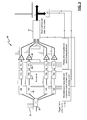
- FIG. 12 is a diagram depicting an arrangement for a pulse-burst stacker having two cascaded stages
- FIG. 13 is a diagram depicting another arrangement for a pulse-burst stacker having two cascaded stages
- FIG. 14 is a diagram depicting coherent pulse stacking with a Gires-Tournois interferometer
- FIG. 15 is a diagram depicting amplitudes of all incident, in-cavity and output pulses in a conceptual 2-mirror GTI cavity
- FIG. 16A is a diagram illustrating m cascaded equal-roundtrip GTI cavities
- FIG. 16B is a diagram illustrating m ⁇ m multiplexed different-roundtrip GTI cavities
- FIGS. 17A-17C are graphs depicting calculated intensities and phases of input pulse bursts and output pulse intensities of four cascaded cavities.
- FIGS. 18A-18C are graphs depicting calculated intensities and phases of input pulse bursts and output pulse intensities of four-by-four multiplexed cavities.
- this disclosure presents beam combining and pulse stacking (in time domain) of solitary pulse bursts.
- This approach allows decoupling of the resonant cavity length from the pulse repetition rate, since this cavity length now determines pulse repetition rate within the solitary pulse burst, while repetition rate between these solitary pulse bursts is completely unconstrained by the combiner size, and, therefore, can be selected completely arbitrarily.
- FIG. 2 illustrates the beam combining and pulse stacking technique using a resonant cavity 20 with two input beams, one beam 22 configured to be reflected and the other beam 23 transmitted by the cavity.
- the resonant cavity 20 is characterized by the fact that the two end mirrors defining it's cavity are each partially reflecting (i.e. each of their reflectivity is less than 100%).
- the resonant cavity 20 is further defined as a Fabry-Perot Interferometer cavity. Other types of resonant cavities are also contemplated by this disclosure.
- each pulse in each of the bursts is characterized by pulses of varying amplitude and phase, which can be easily calculated. Pulse repetition rate in each of the burst will be identical and equal to the RC combiner round-trip time.
- FIG. 3 depicts an example embodiment for implementing the proposed beam combining and pulsing stacking technique which can be contrasted with previous methods.
- a periodic pulse train is split into N equal-amplitude signals, which are then launched into multiple parallel amplification channels.
- Each signal in each individual channel are then uniquely phase modulated so that the frequency-comb structure of each periodic pulse train in each channel is shifted in frequency and the phase being different for each channel.
- Using a suitable selection of these frequency shifts as well as a suitable beam combiner it possible to reconstitute this periodic pulse train, albeit at an N-times reduced repetition frequency.
- a periodic pulse train 31 serves as the input to the beam combining and pulse stacking system 30 .
- the periodic pulse train 30 is first split by a beam splitter 32 into N optical signals.
- the periodic pulse train is then manipulated to form optical signals having one or more clusters of pulses (also referred to herein as pulse bursts), where amplitude and phase of pulses in each cluster varies amongst pulses.
- amplitude and phase modulation are used to carve-out clusters of pulses from the period pulse train.
- An optical amplitude modulator 33 and an optical phase modulator 34 are disposed in each parallel channel.
- the role of the amplitude and phase modulation sequence is to produce pulse burst with the required amplitudes and phases of each individual pulses, so that they can be combined and time-stacked in the properly designed beam combining and pulse stacking arrangements.
- Amplitude and phase modulation pattern for each of the N signals will in general be different between different signals. It is noted that these clusters of pulses can be repeated in time after some arbitrarily chosen time duration T (which is, however, an integer of the original pulse repetition rate), which is not related, and, therefore, can be much longer, than the combining resonator round-trip time.
- Pulses from each of the clusters are combined coherently in the time domain using one or more resonant cavities 37 as will be further described below. It is important that all of the parallel channels be phase locked. Thus, additional phase modulators for phasing-locking the parallel channels (and controlled by properly configured phase-locking circuits) 35 are preferably interposed between phase modulators 34 and the resonant cavity 37 . Note that in some configurations, phase modulators 34 and 35 could be combined into one, performing both pulse-burst phase modulation and parallel-channel phasing with the same device. Prior to coherently combining pulses, it may also be beneficial to amplify each of the N optical signals. In this case, an optical amplifier 36 is disposed in each channel between the phase locking circuit 35 and the resonant cavities 37 .
- the resonant cavities 37 should be actively controlled so that each cavity maintains its round-trip time precisely at its prescribed level, with a prescribed phase shift.
- the RC round-trip time should match the repetition period of the initial pulse train, and, consequently, the pulse repetition period in each pulse burst.
- producing the prescribed phase shift (round-trip phase) for each cavity requires very small (on the order of one optical-cycle of the optical signal) mismatch for each cavity round-trip time.
- all of the beams should be properly arranged to be incident into the resonant cavities as described in more detail below.
- Example implementations for resonant cavity beam combiners and pulse stackers are shown in FIG. 4A-4C .
- a simple flat-mirror Fabry-Perot interferometer cavity is shown in FIG. 4A .
- One advantage of this implementation is that the finesse of the combining cavity is generally low, approximately equal to the number of channels combined in a cascaded scheme. Low-finesse cavities are much easier to align than high-finesse cavities.
- “1” indicates input 1 beam, which is configured to be transmitted through the Fabry-Perot interferometer cavity
- “2” indicates input 2 beam, configured to be reflected from the Fabry-Perot interferometer cavity
- “3” indicates the combined beam comprised of the transmitted and reflected beams.
- FIG. 4B In order to avoid significant beam expansion due to propagation distance in a resonant-cavity combiner, it may be beneficial to include curved refocusing mirrors into an Fabry-Perot interferometer cavity as seen in FIG. 4B .
- the curved mirrors are aligned in such a way that beam size is reproduced exactly every round-trip time in the cavity.
- Configurations in FIGS. 4A and 4B require external separation between the incident reflection-path and the combined beams. This can be done, for example, using a standard polarization beam splitter and a suitable waveplate or a Faraday rotator.
- the configuration shown in FIG. 4C has the advantage that all the incident beams are separate from each other and, most importantly, from the combined beam.
- FIGS. 5A and 5B Two example arrangements are shown in FIGS. 5A and 5B .
- Fabry-Perot interferometer cavities may be arranged in a parallel cascading manner. That is, optical beams are paired together (e.g., #1 and #2) and each pair of optical beams are combined together concurrently using a series of cavities. Combined optical beams are likewise paired together (e.g., 51 and 52 ) and combined with each other using another series of cavities. This arrangement is repeated until two optical beams are combined to form a single optical beam 53 .
- Fabry-Perot interferometer cavities may also be arranged in a sequential cascading manner as seen in FIG. 5B .
- two optical beams e.g., #1 and #2
- the combined beam is then combined with a third beam (i.e., #3) using another cavity.
- This arrangement is again repeated until all of the N optical beams have been combined together to form a single optical beam.
- FIG. 6A illustrate a specific example of combining optical beams using a sequential cascading arrangement.
- six input beams are combined using an array of five Fabry-Perot interferometer cavities. End-of-cavity mirrors are identical for each cavity.
- Each cavity is further characterized by a different mirror reflectivity for each of the cavity mirrors, as well as by individually different phase-shifts produced by each resonant cavity.
- FIGS. 6B-6G depict pulse profiles for the six input beams. More specifically, amplitudes (i.e., peak powers) and phases for each input signal are indicated by red bars and blue circles, respectively. Horizontal axis is labeled in terms of the pulse number in the sequence. Note that earlier time is on the right-hand and later time is toward the left-hand. Specific pulse-burst period value is not important in the calculation and can be freely chosen. For reference, integration of the total pulse energy in each pulse burst (cluster) (red solid line), as well as a horizontal line indicating 1 ⁇ 6 of the total energy obtained by cumulatively summing energies of all the pulses in all the inputs are also shown in the figures.
- each of the six input beams into the sequential cascading arrangement described in FIG. 6A yields an output beam with a single solitary pulse.
- the beam combining and pulse stacking technique can also be extended to a resonant cavity with only one input mirror as seen in FIG. 7 .
- the resonant cavity can be defined by an input mirror 71 having partial reflectivity and the other mirror 72 defining the cavity having 100% reflectivity.
- such cavity could be implemented by a Gires-Tournois interferometer.
- Pulse stacking in time can be achieved similar to the partially-reflecting combiner discussed above. Again, it is possible to calculate the amplitudes and phases for each pulse in the incident pulse burst needed to form a solitary pulse.
- FIG. 8 depicts an example embodiment for implementing the pulsing stacking technique using one or more resonant cavities with 100% reflectivity.
- a single periodic pulse train 81 is input into a sequence of an amplitude modulator 83 and a phase modulator 84 , which again modulate each-pulse amplitude and phase in the solitary pulse burst 85 .
- the pulse-burst can be optionally amplified by an optical amplifier 86 to boost its power, but practical advantages can also be achieved without this amplification.
- the pulse-burst is incident into a pulse stacker arrangement 87 to form an output beam having a solitary pulse.
- the pulse stacker arrangement 87 can be implemented by a single fully reflective resonant cavity or multiple fully reflective resonant cavities as further described below.
- FIG. 9 An alternative embodiment for implementing the pulse stacking technique using one or more fully reflective resonant cavities is shown in FIG. 9 .
- a single periodic pulse train 91 is again input into a sequence of an amplitude modulator 93 and a phase modulator 94 , which modulate each-pulse amplitude and phase in the solitary pulse burst 95 .
- much higher pulse energies and power can be achieved by inserting N parallel-channel amplification array.
- the solitary pulse-burst 95 is split by a beam splitter 92 into N identical optical signals and thereby forming N parallel channels.
- the optical signal is passed through a phase-locking modulator 96 (each controlled by a properly arranged phase-locking electronic circuit) and an optical amplifier 97 .
- the N amplified optical beams are then coherently combined into a single beam using, for example, conventional phasing schemes and conventional beam combiners as indicated at 98 .
- Example beam combiners may include but are not limited to binary-tree combiners or diffractive optical element (DOE) combiners.
- DOE diffractive optical element
- this N-channel array can be configured for a spectral-coherent combining as described in by Wei-zung Chang, Tong Zhou, Leo A. Siiman, and Almantas Galvanauskas in “Femtosecond pulse spectral synthesis in coherently-spectrally combined multi-channel fiber chirped pulse amplifiers,” Opt. Express 21, 3897-3910 (2013).
- this array would allow overcoming not only power limitations, but could also overcome spectral bandwidth limitations of each individual amplification channel. This, for example, can be important when generating ultrashort pulses.
- the N-channel array should contain spectral beam splitting and combining elements as described in the publication noted above. This array could also be a “hybrid” setup containing a combination of both coherent and spectral-coherent combining arrangements.
- FIGS. 10A-10C illustrate example configurations for a fully reflective resonant cavity.
- the second cavity mirror 101 of the cavity is 100% reflective but otherwise these configurations are analogous to those in FIGS. 4A-4C .
- a Gires-Tournois interferometer cavity is an example of such fully reflective resonant cavity although other types of resonant cavities are also contemplated.
- the incident pulse burst There are two general constrains on the incident pulse burst, and on the parameters of the resonant cavity.
- the first constraint is that amplitudes and phases imprinted (using amplitude and phase modulators) on all the pulses in the incident pulse burst should be such that a single stacked pulse is produced at the combiner output.
- This constraint is relevant both for Fabry-Perot and Gires-Toirnois based combining schemes.
- This constraint can be formulated mathematically. As an example let's consider combining of two signals with a single Febry-Perot combiner. Let's denote a single stacked pulse at the combiner output as ⁇ tilde over (p) ⁇ s (t) in the time domain. Spectrum ⁇ tilde over (P) ⁇ s (v) of this pulse can be obtained by fourier transform of this time-domain signal using a standard fourier-transform definition:
- ⁇ tilde over (P) ⁇ s (v) ⁇ tilde over (F) ⁇ R (v) describes the spectrum of the pulse burst incident into the reflection port 1
- ⁇ tilde over (P) ⁇ s (v) ⁇ tilde over (F) ⁇ T (v) the spectrum of the pulse burst incident into the transmission port 2 , that produce the solitary pulse at the output of the Fabry-Perot combiner.
- the case with two different reflectivities can be described by using appropriate reflection and transmission transfer functions for such a cavity.
- ⁇ tilde over (F) ⁇ GTI (v) is a Gires-Tournois cavity spectral transfer function:
- R front-mirror reflectivity
- this transfer function will be 2 ⁇ tilde over (F) ⁇ T (v) ⁇ 1 ⁇ tilde over (F) ⁇ R (v), where 2 ⁇ tilde over (F) ⁇ T (v) is the cavity 2 transfer, and 1 ⁇ tilde over (F) ⁇ R (v) is the cavity 1 reflection functions.
- the second constraint is such that there would be an energy benefit when combining these pulsed bursts. This means that the total energy of the solitary output pulse should be more than N times larger (N being the number of inputs into the combining arrangement) than the highest energy of any individual pulse in all the incident pulse bursts. Otherwise, if this combined-output energy is only N times larger, then this could be achieved with any conventional combining approach. Also, this constraint is relevant only for the Fabry-Perot combining. For the Gires-Tournois combining there always is an energy benefit, as long as a solitary output pulse is produced.
- a reflecting interferometer can be configured either as a linear or a traveling-wave cavity.
- a linear reflecting cavity is essentially a Fabry-Perot interferometer with one completely reflecting mirror, which is commonly referred to as a Gires-Tournois interferometer (GTI).
- GTI Gires-Tournois interferometer
- the practical advantage of a traveling-wave reflecting cavity, shown in FIG. 14 is that it allows one to spatially separate the incident input and reflected output beams. For usage convenience we will also refer to this traveling-wave cavity as a GTI.
- Let's consider a traveling-wave GTI cavity, consisting of a partially reflecting front-mirror M (with power reflectivity R r 2 ⁇ 1), and K completely reflecting beam-folding mirrors M 1 , M 2 , . . .
- ⁇ r 1 ⁇ r 2 ⁇ . . . r K
- r k is a corresponding k-th mirror amplitude reflection coefficient.
- coefficient ⁇ 2 R 1 ⁇ R 2 ⁇ . . . . R K describes power loss per each round trip due to the finite reflectivity of the folding mirrors.
- the incident and reflected fields at both sides of the front mirror M can be described by a unitary scattering matrix [S], which can be written in a symmetric form:
- ⁇ n in A n ⁇ e i ⁇ n is the complex amplitude characterizing the amplitude and phase of the n-th individual pulse in ⁇ tilde over (p) ⁇ n (t) of the semi-infinite input pulse burst.
- the pulse repetition period ⁇ T should be equal to the cavity round trip time ⁇ T, since interference at the front mirror M occurs only when the incident pulse and the circulating in-cavity pulse arrive at that mirror simultaneously. As shown in FIG.
- Eq. (8) and (9) describe an ideal semi-infinite input pulse sequence, when the only output is the stacked pulse.
- the GTI output with a finite sequence input contains both the stacked pulse as well as a weak first-pulse reflection with amplitude out ⁇ N-1 . From Eq. (11) describing out ⁇ N-1 it is also clear that this reflection can be made negligibly small by increasing the length N of the incident pulse burst. For example, for a 9-pulse stacking sequence this reflection peak power can be smaller than 10 ⁇ 3 of the stacked pulse peak power.
- This coherent stacking of multiple pulses into one output pulse containing all the energy of the input pulse sequence is beneficial when amplifying high energy pulses in, e.g. a fiber amplifier, since it enables the amplification of pulses with lower peak powers, thus reducing the detrimental nonlinear effects in an amplifier.
- GTI parameters which minimize the magnitude of max ⁇ in B n ⁇ .
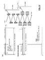
- FIGS. 11A and 11B schematically illustrate pulse stacker arrangements 87 which may be used, for example in the embodiments of FIGS. 8 and 9 .
- FIG. 11A a single resonant cavity with 100% reflectivity is used stack pulses in the time domain.
- FIG. 11B five resonant cavities are arranged in a sequential cascade.
- FIGS. 11C-11G depict examples of calculated pulse-bursts which can serve as input to the sequential cascade of FIG. 11B . It is noted that all pulses in the burst are nearly equal in amplitude, and the number of pulses is approximately equal to the double of number of stages in the cascade. This means that energy enhancement X is approximately equal to 2N, where N is the number of stages in the cascade.
- pulse burst with 2m equal-amplitude pulses can be stacked in a sequence of GTI cavities with m reflectivities r 1 , r 2 , . . . , r m , and m ⁇ 1 round-trip phases ⁇ 1 , ⁇ 2 , . . . , ⁇ m-1 defined by solving these 2m ⁇ 1 equations.
- One of the round-trip phases (for example ⁇ m ) can be freely selected, and only affects the required individual-pulse phases of the input stacking-pulse burst.
- the calculated GTI-cascade parameters R k
- Cascaded equal-roundtrip GTI cavities provide multiple-pulse stacking proportional to the number of GTI cavities. It is possible to achieve a substantially quicker increase in stacking factors by using a multiplexed GTI cavity configuration shown in FIG. 16B .
- This configuration essentially multiplexes a cascade of m equal-roundtrip GTI cavities with an identical cascade of m GTI cavities, but with the second cascade round-trip being more than 2m times longer than that of the first cascade.
- Numerically calculated example for the case of 4 ⁇ 4 multiplexed cavities and the finite input-pulse consisting of 81 equal-amplitude pulses is shown in FIGS. 18A-18C using the same GTI front mirror reflectivities and cavity round-trip phases as in the previous example of 4 cascaded cavities. It shows that using multiplexing of eight GTI cavities one can achieve stacked peak-power enhancement close to 80.
- This multiplexed cascaded scheme can be generalized to the scheme shown in FIG. 12 , where the multiplexed sequential cascades contain different number of GTI elements, not just the equal number as described above.
- the scheme employs two or more stages, each stage comprised of a sequentially cascaded resonant cavities.
- a first stage is comprised of N 1 resonant cavities and a second state is comprised of N 2 resonant cavities.
- These two different stages are distinguished from each other by the fact that the round trip time for all RC cavities in the first cascade is t 1 , whereas, the round trip time for all RC cavities in the second cascade is 2N 1 t 1 .
- the input signal now consists of 2N 2 bursts, each burst consisting of 2N 1 pulses.
- the 2N 1 pulses in each burst are configured in such a way that each burst is stacked into a single pulse at the output of the first cascade. Consequently, at the output of the first cascade, a sequence of 2N 2 pulses is produced.
- the sequence is configured in such a way (by choosing the suitable phase of each individual pulse-burst in the initial sequence) that the two solitary pulses are in turn stacked again in the second cascade to form an output with a single pulse. Assuming that the equal amplitude pulse format as shown in FIG.
- Signal combining both spatially and temporally partially-reflecting resonator cavities and completely-reflecting resonator cavities (temporally combining) can be combined as shown in FIG. 13 .
- Such a configuration represents a general beam combining and pulse stacking arrangement shown in FIG. 3 . Note that this is merely an example and different variations of the configuration could be used as well.
- the parallel cascade can replace the sequential cascade of Fabry-Perot type cavities.
- DPA divided pulse amplification
Landscapes
- Physics & Mathematics (AREA)
- Electromagnetism (AREA)
- Engineering & Computer Science (AREA)
- Plasma & Fusion (AREA)
- Optics & Photonics (AREA)
- Optical Communication System (AREA)
Abstract
Description
R 1=0.7143, Δφ1=0
R 2=0.6619, Δφ2=π/3
R 3=0.5845, Δφ3=2(π/3)
R 4=0.4565, Δφ4=3(π/3)
R 5=0.1956, Δφ5=4(π/3)
It is readily understood that values will differ for other arrangements.
Fabry-Perot spectral transfer functions for reflection {tilde over (F)}R(v) and transmission {tilde over (F)}T(v) are:
In this example we take a Fabry-Perot configuration from
{tilde over (P)} s(v)·{tilde over (F)} R(v)+{tilde over (P)} s(v)·{tilde over (F)} T(v)={tilde over (P)} s(v).
{tilde over (P)} s(v)·{tilde over (F)} GTI(v)={tilde over (P)} s(v),
where left-hand term defines the incident pulse spectrum required to produce a single solitary output pulse. Here {tilde over (F)}GTI(v) is a Gires-Tournois cavity spectral transfer function:
Let's choose the time axis reference such that this output stacked pulse is centered at t=0. Then we can enumerate all the pulses in the incident train as
for each n=0, 1, 2, . . . .
Correspondingly, peak power coefficients inBn=|inÃn|2 of the incident pulses are:
Note that by defining the output stacked pulse using Eq. (3) we chose its peak power coefficient to be normalized to 1: outB0=1. In an ideal case, when amplitudes of all the pulses in the semi-infinite input train fulfill the Eq. (8), then all other output pulses are absent, i.e. outBn=0 for all n≠0. According to Eq. (8), if the GTI cavity round trip phase is chosen to be δ=2πm (where m is an integer) then the last pulse in the input sequence is out of phase with respect to the rest of the pulses in the sequence. It is easy to recognize from Eq. (9) that the peak powers of all the pulses in the input sequence prior to the last pulse (i.e. n=1, 2, . . . ) are described by a decreasing geometrical progression.
Here we use the lowercase letters ã instead of à to distinguish between the (N−1)st pulse amplitude coefficients in the finite and semi-infinite sequences respectively, as shown in
From this it is clear that the amplitude coefficient of the first input pulse in the finite sequence is by a
η=out B 0/max{in B n}=1/max{in B n}, (12)
where max{inBn} denotes the highest peak-power coefficient in the incident pulse sequence. One can maximize this peak-power enhancement factor by selecting GTI parameters, which minimize the magnitude of max{inBn}. By inspecting Eq. (9) it is straightforward to recognize that maxη is achieved when inB0=inB1. This condition defines the optimum front-mirror reflectivity Ropt of a GTI cavity:
The solution of this quadratic algebraic equation, corresponding to a physically meaningful power reflectivity in the
Corresponding maxη is
For an ideal case when α2=1 (all folding mirrors are perfectly reflecting) we have Ropt=0.382, and the corresponding highest possible peak-power enhancement for a single GTI cavity of maxη=2.62.
Claims (18)
Priority Applications (1)
| Application Number | Priority Date | Filing Date | Title |
|---|---|---|---|
| US15/104,924 US9865986B2 (en) | 2013-12-19 | 2014-12-19 | Coherent combining pulse bursts in time domain |
Applications Claiming Priority (3)
| Application Number | Priority Date | Filing Date | Title |
|---|---|---|---|
| US201361918485P | 2013-12-19 | 2013-12-19 | |
| PCT/US2014/071585 WO2015095751A1 (en) | 2013-12-19 | 2014-12-19 | Coherently combining pulse bursts in time domain |
| US15/104,924 US9865986B2 (en) | 2013-12-19 | 2014-12-19 | Coherent combining pulse bursts in time domain |
Related Parent Applications (1)
| Application Number | Title | Priority Date | Filing Date |
|---|---|---|---|
| PCT/US2014/071585 A-371-Of-International WO2015095751A1 (en) | 2013-12-19 | 2014-12-19 | Coherently combining pulse bursts in time domain |
Related Child Applications (1)
| Application Number | Title | Priority Date | Filing Date |
|---|---|---|---|
| US15/724,723 Continuation US10312657B2 (en) | 2013-12-19 | 2017-10-04 | Coherent combining pulse bursts in time domain |
Publications (2)
| Publication Number | Publication Date |
|---|---|
| US20160315441A1 US20160315441A1 (en) | 2016-10-27 |
| US9865986B2 true US9865986B2 (en) | 2018-01-09 |
Family
ID=53403758
Family Applications (2)
| Application Number | Title | Priority Date | Filing Date |
|---|---|---|---|
| US15/104,924 Active US9865986B2 (en) | 2013-12-19 | 2014-12-19 | Coherent combining pulse bursts in time domain |
| US15/724,723 Active US10312657B2 (en) | 2013-12-19 | 2017-10-04 | Coherent combining pulse bursts in time domain |
Family Applications After (1)
| Application Number | Title | Priority Date | Filing Date |
|---|---|---|---|
| US15/724,723 Active US10312657B2 (en) | 2013-12-19 | 2017-10-04 | Coherent combining pulse bursts in time domain |
Country Status (2)
| Country | Link |
|---|---|
| US (2) | US9865986B2 (en) |
| WO (1) | WO2015095751A1 (en) |
Cited By (3)
| Publication number | Priority date | Publication date | Assignee | Title |
|---|---|---|---|---|
| US10312657B2 (en) * | 2013-12-19 | 2019-06-04 | The Regents Of The University Of Michigan | Coherent combining pulse bursts in time domain |
| US11221541B2 (en) * | 2018-06-12 | 2022-01-11 | The George Washington University | Optical digital to analog converter using seriated splitters |
| EP4550355A3 (en) * | 2023-11-02 | 2025-06-25 | Blue Laser Fusion, Inc. | System and method for beam shaped laser coupled to optical cavity |
Families Citing this family (4)
| Publication number | Priority date | Publication date | Assignee | Title |
|---|---|---|---|---|
| US11043783B2 (en) | 2015-12-23 | 2021-06-22 | Fraunhoer-Gesellschaft zur Förderung der angewandten Forschung e.V. | Optical arrangement |
| GB2575627B (en) * | 2018-06-29 | 2023-03-01 | M Squared Lasers Ltd | Laser System for Coherently Combining Multiple Laser Sources |
| WO2021071836A1 (en) * | 2019-10-06 | 2021-04-15 | The Regents Of The University Of Michigan | Spectrally and coherently combined laser array |
| CN112570897B (en) * | 2020-11-17 | 2023-03-24 | 华东师范大学重庆研究院 | Femtosecond pulse cluster generation method and quartz micro-fluidic chip manufacturing device |
Citations (7)
| Publication number | Priority date | Publication date | Assignee | Title |
|---|---|---|---|---|
| US20050232182A1 (en) | 1998-02-12 | 2005-10-20 | Shattil Steve J | Frequency-shifted feedback cavity used as a phased array antenna controller and carrier interference multiple access spread-spectrum transmitter |
| US20050232317A1 (en) | 2001-01-30 | 2005-10-20 | Marcos Dantus | Control system and apparatus for use with laser excitation and ionization |
| US20070280398A1 (en) | 2005-12-05 | 2007-12-06 | Dardik Irving I | Modified electrodes for low energy nuclear reaction power generators |
| US20090161034A1 (en) | 2004-06-14 | 2009-06-25 | David Coates | Drive schemes for driving cholesteric liquid crystal material into the focal conic state |
| US20130148128A1 (en) | 2009-03-06 | 2013-06-13 | Imra America, Inc. | Optical scanning and imaging systems based on dual pulsed laser systems |
| WO2013188349A2 (en) | 2012-06-11 | 2013-12-19 | The Regents Of The University Of Michigan | N2 times pulse energy enhancement using coherent addition of n orthogonally phase modulated periodic signals |
| US9166355B2 (en) * | 2011-09-12 | 2015-10-20 | Lawrence Livermore National Security, Llc | Directly driven source of multi-gigahertz, sub-picosecond optical pulses |
Family Cites Families (1)
| Publication number | Priority date | Publication date | Assignee | Title |
|---|---|---|---|---|
| US9865986B2 (en) * | 2013-12-19 | 2018-01-09 | The Regents Of The University Of Michigan | Coherent combining pulse bursts in time domain |
-
2014
- 2014-12-19 US US15/104,924 patent/US9865986B2/en active Active
- 2014-12-19 WO PCT/US2014/071585 patent/WO2015095751A1/en not_active Ceased
-
2017
- 2017-10-04 US US15/724,723 patent/US10312657B2/en active Active
Patent Citations (7)
| Publication number | Priority date | Publication date | Assignee | Title |
|---|---|---|---|---|
| US20050232182A1 (en) | 1998-02-12 | 2005-10-20 | Shattil Steve J | Frequency-shifted feedback cavity used as a phased array antenna controller and carrier interference multiple access spread-spectrum transmitter |
| US20050232317A1 (en) | 2001-01-30 | 2005-10-20 | Marcos Dantus | Control system and apparatus for use with laser excitation and ionization |
| US20090161034A1 (en) | 2004-06-14 | 2009-06-25 | David Coates | Drive schemes for driving cholesteric liquid crystal material into the focal conic state |
| US20070280398A1 (en) | 2005-12-05 | 2007-12-06 | Dardik Irving I | Modified electrodes for low energy nuclear reaction power generators |
| US20130148128A1 (en) | 2009-03-06 | 2013-06-13 | Imra America, Inc. | Optical scanning and imaging systems based on dual pulsed laser systems |
| US9166355B2 (en) * | 2011-09-12 | 2015-10-20 | Lawrence Livermore National Security, Llc | Directly driven source of multi-gigahertz, sub-picosecond optical pulses |
| WO2013188349A2 (en) | 2012-06-11 | 2013-12-19 | The Regents Of The University Of Michigan | N2 times pulse energy enhancement using coherent addition of n orthogonally phase modulated periodic signals |
Non-Patent Citations (1)
| Title |
|---|
| International Search Report and Written Opinion for PCT/US2014/071585, dated Apr. 22, 2015; ISA/KR. |
Cited By (4)
| Publication number | Priority date | Publication date | Assignee | Title |
|---|---|---|---|---|
| US10312657B2 (en) * | 2013-12-19 | 2019-06-04 | The Regents Of The University Of Michigan | Coherent combining pulse bursts in time domain |
| US11221541B2 (en) * | 2018-06-12 | 2022-01-11 | The George Washington University | Optical digital to analog converter using seriated splitters |
| US11719995B2 (en) | 2018-06-12 | 2023-08-08 | The George Washington University | Optical digital to analog converter using electro-modulated waveguides |
| EP4550355A3 (en) * | 2023-11-02 | 2025-06-25 | Blue Laser Fusion, Inc. | System and method for beam shaped laser coupled to optical cavity |
Also Published As
| Publication number | Publication date |
|---|---|
| WO2015095751A1 (en) | 2015-06-25 |
| US10312657B2 (en) | 2019-06-04 |
| US20180026418A1 (en) | 2018-01-25 |
| US20160315441A1 (en) | 2016-10-27 |
Similar Documents
| Publication | Publication Date | Title |
|---|---|---|
| US10312657B2 (en) | Coherent combining pulse bursts in time domain | |
| Zhou et al. | Coherent pulse stacking amplification using low-finesse Gires-Tournois interferometers | |
| Chen et al. | Demonstration of a quantum controlled-NOT gate in the telecommunications band | |
| US9810967B2 (en) | Method and apparatus for generation of coherent frequency combs | |
| US20110280581A1 (en) | Systems and methods for producing high-power laser beams | |
| US10958034B2 (en) | Narrowband depolarized fiber lasers | |
| US20110292498A1 (en) | High peak power optical amplifier | |
| Huang et al. | Spectral line‐by‐line shaping for optical and microwave arbitrary waveform generations | |
| US9503196B2 (en) | N2 times pulse energy enhancement using coherent addition of N orthogonally phase modulated periodic signals | |
| JP6057992B2 (en) | Passive apparatus and method for coherent coupling of multiple optical amplifiers | |
| CN203012249U (en) | Pulse Laser Polarization Beam Combiner | |
| US9941653B2 (en) | Optical array comprising a beam splitter | |
| JP2022546299A (en) | Resistance of fiber amplifier systems to nonlinear spectral broadening and decoherence | |
| CN109818237B (en) | Ultrashort laser pulse shaping system based on optical fiber ring circulation modulation time grating | |
| CN115513756B (en) | A high-power and high-energy femtosecond laser with acousto-optic beam combining and laser beam combining method thereof | |
| JP7320007B2 (en) | Common Drive Electro-Optical Phase Modulator Array | |
| Azaña et al. | Multiwavelength optical signal processing using multistage ring resonators | |
| CN105762623B (en) | High power single-frequency pulse full-fiber laser | |
| JP3439345B2 (en) | Wavelength converter and wavelength conversion method | |
| CN207967581U (en) | Chirped laser pulse frequency spectrum shaping system based on spectrum angle dispersion | |
| Lee et al. | Bright, Waveguide-based Entanglement Sources for High-rate Quantum Networking | |
| Zhou et al. | Resonant cavity based time-domain multiplexing techniques for coherently combined fiber laser systems | |
| Hakimi et al. | A new wide-band pulse-restoration technique for digital fiber-optic communication systems using temporal gratings | |
| Radic et al. | Stimulated-Brillouin-scattering suppression using a single modulator in two-pump parametric architectures | |
| Cooper et al. | Coherent Temporal Stacking of Tens-of-fs Laser Pulses Towards Plasma Accelerator Applications |
Legal Events
| Date | Code | Title | Description |
|---|---|---|---|
| AS | Assignment |
Owner name: THE REGENTS OF THE UNIVERSITY OF MICHIGAN, MICHIGA Free format text: ASSIGNMENT OF ASSIGNORS INTEREST;ASSIGNOR:GALVANAUSKAS, ALMANTAS;REEL/FRAME:038923/0372 Effective date: 20150414 |
|
| STCF | Information on status: patent grant |
Free format text: PATENTED CASE |
|
| AS | Assignment |
Owner name: UNITED STATES DEPARTMENT OF ENERGY, DISTRICT OF CO Free format text: CONFIRMATORY LICENSE;ASSIGNOR:UNIVERSITY OF MICHIGAN;REEL/FRAME:050104/0581 Effective date: 20190130 |
|
| MAFP | Maintenance fee payment |
Free format text: PAYMENT OF MAINTENANCE FEE, 4TH YR, SMALL ENTITY (ORIGINAL EVENT CODE: M2551); ENTITY STATUS OF PATENT OWNER: SMALL ENTITY Year of fee payment: 4 |
|
| MAFP | Maintenance fee payment |
Free format text: PAYMENT OF MAINTENANCE FEE, 8TH YR, SMALL ENTITY (ORIGINAL EVENT CODE: M2552); ENTITY STATUS OF PATENT OWNER: SMALL ENTITY Year of fee payment: 8 |