US9833289B2 - Method and apparatus for a radiolucent and MRI compatible cranial stabilization pin - Google Patents
Method and apparatus for a radiolucent and MRI compatible cranial stabilization pin Download PDFInfo
- Publication number
- US9833289B2 US9833289B2 US14/674,013 US201514674013A US9833289B2 US 9833289 B2 US9833289 B2 US 9833289B2 US 201514674013 A US201514674013 A US 201514674013A US 9833289 B2 US9833289 B2 US 9833289B2
- Authority
- US
- United States
- Prior art keywords
- tip
- pin
- skull
- molded body
- versions
- Prior art date
- Legal status (The legal status is an assumption and is not a legal conclusion. Google has not performed a legal analysis and makes no representation as to the accuracy of the status listed.)
- Active, expires
Links
Images


Classifications
-
- A61B19/203—
-
- A61B5/0555—
-
- A—HUMAN NECESSITIES
- A61—MEDICAL OR VETERINARY SCIENCE; HYGIENE
- A61B—DIAGNOSIS; SURGERY; IDENTIFICATION
- A61B6/00—Apparatus or devices for radiation diagnosis; Apparatus or devices for radiation diagnosis combined with radiation therapy equipment
- A61B6/02—Arrangements for diagnosis sequentially in different planes; Stereoscopic radiation diagnosis
- A61B6/03—Computed tomography [CT]
- A61B6/032—Transmission computed tomography [CT]
-
- A—HUMAN NECESSITIES
- A61—MEDICAL OR VETERINARY SCIENCE; HYGIENE
- A61B—DIAGNOSIS; SURGERY; IDENTIFICATION
- A61B6/00—Apparatus or devices for radiation diagnosis; Apparatus or devices for radiation diagnosis combined with radiation therapy equipment
- A61B6/04—Positioning of patients; Tiltable beds or the like
-
- A—HUMAN NECESSITIES
- A61—MEDICAL OR VETERINARY SCIENCE; HYGIENE
- A61B—DIAGNOSIS; SURGERY; IDENTIFICATION
- A61B90/00—Instruments, implements or accessories specially adapted for surgery or diagnosis and not covered by any of the groups A61B1/00 - A61B50/00, e.g. for luxation treatment or for protecting wound edges
- A61B90/10—Instruments, implements or accessories specially adapted for surgery or diagnosis and not covered by any of the groups A61B1/00 - A61B50/00, e.g. for luxation treatment or for protecting wound edges for stereotaxic surgery, e.g. frame-based stereotaxis
- A61B90/14—Fixators for body parts, e.g. skull clamps; Constructional details of fixators, e.g. pins
-
- A—HUMAN NECESSITIES
- A61—MEDICAL OR VETERINARY SCIENCE; HYGIENE
- A61B—DIAGNOSIS; SURGERY; IDENTIFICATION
- A61B17/00—Surgical instruments, devices or methods
- A61B2017/00831—Material properties
- A61B2017/00902—Material properties transparent or translucent
- A61B2017/00911—Material properties transparent or translucent for fields applied by a magnetic resonance imaging system
-
- A—HUMAN NECESSITIES
- A61—MEDICAL OR VETERINARY SCIENCE; HYGIENE
- A61B—DIAGNOSIS; SURGERY; IDENTIFICATION
- A61B17/00—Surgical instruments, devices or methods
- A61B2017/00831—Material properties
- A61B2017/00902—Material properties transparent or translucent
- A61B2017/00915—Material properties transparent or translucent for radioactive radiation
- A61B2017/0092—Material properties transparent or translucent for radioactive radiation for X-rays
Definitions
- a portion of the body upon which surgery is being conducted may be substantially immobilized, such as, for example, a patient's head during head or neck surgery.
- immobilization of a patient's head may be accomplished with a fixture such as a skull clamp or other fixture, as disclosed in U.S. Pat. No. 7,836,532, entitled METHOD AND APPARATUS FOR ATTACHING ACCESSORIES TO A SURGICAL FIXTURE, issued Nov. 23, 2010, and in U.S. Patent Publication No.
- cranial stabilization systems and components include any of the DORO products of pro med instruments GmbH of Freiburg, Germany. These and other devices may be used with cranial stabilization pins, also referred to as skull pins, which may be used to securely hold a patient's head within the skull clamp or other device.
- a cranial immobilization system or technique with a surgical procedure using intra-operative computed tomography (CT) scanning or other types of imaging (e.g., MRI, PEM, X-Ray, etc.).
- CT computed tomography
- components of the cranial immobilization system may be compatible with the imaging technology, e.g. MRI, and further radiolucent.
- the skull pins be substantially or completely radiolucent and safe for use with MRI, yet still provide sufficient durability in use. While many surgical accessories and immobilization fixtures exist, it is believed that no one prior to the inventors has created or used the invention described herein.
- FIG. 1 depicts a perspective view of an exemplary cranial stabilization pin.
- FIG. 2 depicts a side view of the pin of FIG. 1 .
- FIG. 3 depicts a cross section view of the pin of FIG. 2 , taken along line 3 - 3 of FIG. 2 .
- FIG. 4 depicts a perspective view of the tip of the pin of FIG. 1 .
- FIG. 5 depicts a side view of the tip of FIG. 4 .
- FIG. 6 depicts a cross section view of the tip of FIG. 5 , taken along the line 6 - 6 of FIG. 5 .
- FIG. 7 depicts a cross section view of another exemplary cranial stabilization pin, taken along a line similar to that of the cross section view of FIG. 3 but for another exemplary pin that is not shown in perspective and side views but would otherwise be identical to the perspective and side views of FIGS. 1 and 2 .
- FIG. 8 depicts a perspective view of the tip of the pin of FIG. 7 .
- FIG. 9 depicts a side view of the tip of FIG. 8 .
- FIG. 10 depicts a cross section view of the tip of FIG. 9 , taken along line 10 - 10 of FIG. 9 .
- FIG. 11 depicts a perspective view of another exemplary cranial stabilization pin.
- FIG. 12 depicts a side view of the pin of FIG. 11 .
- FIG. 13 depicts a cross section view of the pin of FIG. 12 , taken along line 13 - 13 of FIG. 12 .
- FIG. 14 depicts a perspective view of the tip of the pin of FIG. 11 .
- FIG. 15 depicts a side view of the tip of FIG. 14 .
- FIG. 16 depicts a cross section view of the tip of FIG. 15 , taken along line 16 - 16 of FIG. 15 .
- FIG. 17 depicts a perspective view of another exemplary cranial stabilization pin.
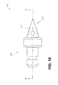
- FIG. 18 depicts a side view of the pin of FIG. 17 .
- FIG. 19 depicts a cross section view of the pin of FIG. 18 , taken along line 19 - 19 of FIG. 18 .
- FIG. 20 depicts a perspective view of the tip of the pin of FIG. 17 .
- FIG. 21 depicts a side view of the tip of FIG. 20 .
- FIG. 22 depicts a cross section view of the tip of FIG. 21 , taken along the line 22 - 22 of FIG. 21 .
- FIG. 23 depicts a perspective view of another exemplary tip for use in a cranial stabilization pin.
- FIG. 24 depicts a side view of another exemplary tip for use in a cranial stabilization pin.
- FIG. 25 depicts a perspective view of another exemplary tip for use in a cranial stabilization pin.
- FIG. 26 depicts a side view of the tip of FIG. 25 .
- FIG. 27 depicts a cross section view of the tip of FIG. 25 , taken along the line 27 - 27 of FIG. 26 .
- FIG. 28 depicts a cross section view of another exemplary cranial stabilization pin with the tip encased within the body.
- FIG. 29 depicts a perspective view of another exemplary stabilization pin.
- FIG. 30 depicts a cross-sectional side view of the pin of FIG. 29 .
- FIG. 31 depicts an exploded cross-sectional side view of the pin of FIG. 29 .
- FIGS. 1-31 depict various views of exemplary cranial stabilization pins, or components thereof, configured for use in a cranial immobilization fixture as referenced and described above.
- Such cranial stabilization pins are sometimes referred to as skull pins, or pins.
- the pins are configured to be safe for use with and compatible with imaging techniques including x-ray, computed tomography (CT) and magnetic resonance (MR).
- CT computed tomography
- MR magnetic resonance
- the pins are at least partially radiolucent and are configured to produce only a minimal artifact in the output of an imaging scan.
- the pins are constructed such that they can withstand the torque and axial forces typical in a skull stabilization procedure.
- Pin ( 10 ) comprises a body ( 100 ) and tip ( 200 ).
- Body ( 100 ) comprises proximal end ( 102 ) and distal end ( 104 ).
- Proximal end ( 102 ) is configured for secure attachment with a pin-holding component of a skull clamp or other device, e.g. a skull clamp as described in U.S. Pat. No. 7,836,532, entitled METHOD AND APPARATUS FOR ATTACHING ACCESSORIES TO A SURGICAL FIXTURE, issued Nov. 23, 2010, or in U.S. Patent Publication No.
- proximal end ( 102 ) has a generally cylindrical shape that is configured to fit within a matching bore of a pin-holding component of a skull clamp.
- proximal end ( 102 ) includes an annular recess ( 106 ). Annular recess ( 106 ) allows for a pin-holding component of a skull clamp to grip proximal end ( 102 ) of pin ( 10 ).
- Annular recess ( 106 ) may also be fitted with an o-ring (not shown) to assist in securing to the pin-holding component of a skull clamp or other device.
- proximal end ( 102 ) lacks annular recess ( 106 ).
- Other suitable features and configurations that may be provided at proximal end ( 102 ) such that pin ( 10 ) can be associated with a pin-holding component of a skull clamp or other device will be apparent to those of ordinary skill in the art in view of the teachings herein.
- Distal end ( 104 ) of pin ( 10 ) of the present example comprises annular collar ( 108 ) and a conical protrusion ( 110 ).
- Annular collar ( 108 ) provides first surface ( 112 ) that is configured to act as a stop by contacting a portion of a pin-holding component of a skull clamp or other device.
- Conical protrusion ( 110 ) extends distally from body ( 100 ), tapering from larger to smaller diameter as protrusion ( 110 ) extends distally. At a distal-most end, conical protrusion ( 110 ) is associated with tip ( 200 ).
- distal end ( 104 ) of pin ( 10 ) may have a variety of other types of features and configurations in addition to or in lieu of having annular collar ( 108 ) and/or conical protrusion ( 110 ).
- Tip ( 200 ) is largely a hollow structure comprising shaft ( 202 ) and conical protrusion ( 204 ).
- Shaft ( 202 ) is located along proximal end ( 206 ) of tip ( 200 ), and conical protrusion ( 204 ) is located along distal end ( 208 ) of tip ( 200 ).
- Conical protrusion ( 204 ) extends distally from shaft ( 202 ), tapering to a point at its distal-most end.
- conical protrusion ( 204 ) includes lip ( 210 ).
- Lip ( 210 ) has a diameter greater than shaft ( 202 ) such that lip ( 210 ) overhangs shaft ( 202 ).
- Shaft ( 202 ) comprises sidewall ( 212 ), and sidewall ( 212 ) is configured with one or more openings ( 214 ).
- sidewall ( 212 ) includes two circular-shaped openings ( 214 ).
- Shaft ( 202 ) also comprises open end ( 216 ), which provides access to void space ( 224 ) within tip ( 200 ).
- tip ( 200 ) is constructed from a non-magnetic metal, such as titanium.
- a solid piece of titanium is milled and/or turned to create the general shape as shown in FIGS. 4 and 5 .
- the shaped titanium piece is drilled to incorporate openings ( 214 ) in sidewall ( 212 ).
- An additional drilling act is then used to hollow-out tip ( 200 ) by drilling along the longitudinal axis of tip ( 200 ) to create open end ( 216 ) and void space ( 224 ).
- suitable materials to fabric the tips disclosed herein may include ceramics, other non-magnetic metals, glass-fiber reinforced materials, carbon-fiber reinforced materials, among others.
- body ( 100 ) is constructed from a plastic by an injection molding process.
- Suitable plastics may include polyether-etherketone (PEEK), duroplastic, and/or other thermoplastics or thermosetting plastics, all or any of which may include glass-fiber and/or carbon-fiber reinforcement.
- body ( 100 ) and tip ( 200 ) are securely joined via the injection molding process.
- tip ( 200 ) is positioned within the injection mold as an insert, and body ( 100 ) is molded around and within tip ( 200 ).
- the molten plastic flows into void space ( 224 ) of tip ( 200 ) via open end ( 216 ) of shaft ( 202 ) and openings ( 214 ) in sidewall ( 212 ).
- the molten plastic fills void space ( 224 ) within tip ( 200 ) and overflows to encapsulate shaft ( 202 ).
- the shape of the mold is such that the molten plastic continues to form body ( 100 ) in the shape as shown in FIGS. 1-2 .
- cross sections of pin ( 10 ) and tip ( 200 ) show that final pin ( 10 ), in an injection molded design, has the plastic of body ( 100 ) encompassing void space ( 224 ) of tip ( 200 ) and surrounding proximal end ( 206 ) of tip ( 200 ) where shaft ( 202 ) is located. Also, lip ( 210 ) of tip ( 200 ) abuts conical protrusion ( 110 ) of body ( 100 ) to provide a smooth transition from tip ( 200 ) to body ( 100 ).
- pin ( 10 ) is safe for use with and compatible with MR imaging, and pin ( 10 ) is substantially radiolucent with a strong tip ( 200 ) having low mass such that only a minimal artifact is seen in the output of an imaging scan. Furthermore, using such a design and fabrication process, tip ( 200 ) and body ( 100 ) are securely joined such that pin ( 10 ) can withstand the torque and axial forces typical in a skull stabilization procedure using a skull clamp or other device.
- molding body ( 100 ) to tip ( 200 ) by molding plastic not only around the exterior surface of a portion of a low mass tip ( 200 ), but also within and through portions of tip ( 200 ) provides as strong and secure connection between body ( 100 ) and tip ( 200 ), suitable for withstanding torque and axial forces experienced in use.
- body ( 100 ) has been described as being constructed of plastic, and by an injection molding process, other suitable materials and methods of construction will be apparent to those of ordinary skill in the art in view the teachings herein.
- body ( 100 ) may be fabricated by machining by turning, milling, etc. instead of injection molding.
- tip ( 200 ) and body ( 100 ) may be securely joined with an adhesive.
- pin ( 20 ) generally has the same or similar appearance as pin ( 10 ), as shown in FIGS. 1-2 .
- pin ( 20 ) is identical to pin ( 10 ) with the exception that pin ( 20 ) comprises a different tip.
- the functionality of pin ( 20 ) is the same or similar to pin ( 10 ) and the preceding paragraphs describing the functionality of pin ( 10 ) apply equally to pin ( 20 ).
- Pin ( 20 ) comprises body ( 300 ) and tip ( 400 ).
- Tip ( 400 ) is largely a hollow structure comprising shaft ( 402 ), conical protrusion ( 404 ), and collar ( 405 ).
- Collar ( 405 ) is located along proximal end ( 406 ) of tip ( 400 ), and conical protrusion ( 404 ) is located along distal end ( 408 ) of tip ( 400 ).
- Shaft ( 402 ) extends between collar ( 405 ) and conical protrusion ( 404 ).
- Conical protrusion ( 404 ) extends distally from shaft ( 402 ), tapering to a point at its distal-most end.
- conical protrusion ( 404 ) includes lip ( 410 ).
- Lip ( 410 ) has a diameter greater than shaft ( 402 ) such that lip ( 410 ) overhangs shaft ( 402 ).
- shaft ( 402 ) comprises sidewall ( 412 ) that is without openings as described above with respect to pin ( 10 ).
- openings similar to that shown with pin ( 10 ) may be incorporated into sidewall ( 412 ) of shaft ( 402 ).
- Shaft ( 402 ) extends proximally from lip ( 410 ) of conical protrusion ( 404 ) and terminates with its connection to collar ( 405 ).
- collar ( 405 ) comprises a general u-shape, having circular flange portion ( 418 ) with first and second fins ( 420 , 422 ) extending proximally from flange portion ( 418 ).
- Collar ( 405 ) also comprises open end ( 416 ) in the center of flange portion ( 418 ), which provides access to void space ( 424 ) within tip ( 400 ).
- collar ( 405 ) may have shapes other than a u-shape, e.g. a circular shape the same as or similar to that shown in FIG. 24 .
- tip ( 400 ) is constructed from a non-magnetic metal, such as titanium.
- a solid piece of titanium is milled and/or turned to create the general shape as shown in FIGS. 8 and 9 .
- the shaped titanium piece is drilled to hollow-out tip ( 400 ) by drilling along the longitudinal axis of tip ( 400 ). For example, drilling creates open end ( 416 ) of collar ( 405 ) and void space ( 424 ) extending from open end ( 416 ) through flange portion ( 418 ), through shaft ( 402 ), and into conical protrusion ( 404 ).
- other ways to fabricate tip ( 400 ) and other materials suitable for tip ( 400 ) will be apparent to those of ordinary skill in the art.
- body ( 300 ) is constructed from a plastic by an injection molding process.
- Suitable plastics may include polyether-etherketone (PEEK), duroplastic, and/or other thermoplastics or thermosetting plastics, all or any of which may include glass-fiber and/or carbon-fiber reinforcement.
- body ( 300 ) and tip ( 400 ) are securely joined via the injection molding process.
- tip ( 400 ) is positioned within the injection mold as an insert, and body ( 300 ) is molded around and within tip ( 400 ). Where such a process is used, the molten plastic flows into void space ( 424 ) of tip ( 400 ) via open end ( 416 ) of collar ( 405 ).
- the molten plastic fills void space ( 424 ) within tip ( 400 ) and also surrounds shaft ( 402 ) and collar ( 405 ). The molten plastic further fills the space ( 426 ) of collar ( 405 ) between fins ( 420 , 422 ).
- the shape of the mold is such that the molten plastic continues to form body ( 300 ) in the shape as shown in FIGS. 1-2 .
- cross sections of pin ( 20 ) and tip ( 400 ) show that final pin ( 20 ), in a molded design, has the plastic of body ( 100 ) encompassing void space ( 424 ) of tip ( 400 ) and surrounding shaft ( 402 ) and collar ( 405 ) of tip ( 400 ). Also, lip ( 410 ) of tip ( 400 ) abuts conical protrusion ( 310 ) of body ( 300 ) to provide a smooth transition from tip ( 400 ) to body ( 300 ).
- pin ( 20 ) is safe for use with and compatible with MR imaging, and is substantially radiolucent with a strong tip ( 400 ) having low mass such that only a minimal artifact is seen in the output of an imaging scan. Furthermore, using such a design and fabrication process, tip ( 400 ) and body ( 300 ) are securely joined such that pin ( 20 ) can withstand the torque and axial forces typical in a skull stabilization procedure using a skull clamp or other device.
- molding body ( 300 ) to tip ( 400 ) by molding plastic not only around the exterior surface of a portion of a low mass tip ( 400 ), but also within and through portions of tip ( 400 ) provides as strong and secure connection between body ( 300 ) and tip ( 400 ), suitable for withstanding torque and axial forces experienced in use.
- body ( 300 ) has been described as being constructed of plastic, and by an injection molding process, other suitable materials of construction and processes by which to construct body ( 300 ) will be apparent to those of ordinary skill in the art in view of the teachings herein.
- body ( 300 ) may be fabricated by machining by turning, milling, etc. instead of injection molding.
- tip ( 400 ) and body ( 300 ) may be securely joined with an adhesive.
- Skull pin ( 30 ) comprises body ( 500 ) and tip ( 600 ).
- Tip ( 600 ) is constructed from a non-ferrous, non-magnetic, biocompatible, and suitably strong material.
- a suitable material for tip ( 600 ) is titanium.
- tip ( 600 ) comprises a cone-shape having inner cavity ( 602 ), sidewall ( 604 ), and at least one opening ( 606 ) in sidewall ( 604 ).
- Sidewall ( 604 ) has a thickness that is sufficient to provide the necessary strength during use to avoid failure of pin ( 30 ), while limiting the mass of tip ( 600 ) such that only minimal artifacts appear in the output of an imaging scan.
- the thickness of sidewall ( 604 ) is in the range of 0.1 mm to 1 mm.
- the thickness of sidewall ( 604 ) may be altered in some versions based on the application, imagining technique, and/or other strength influencing factors, e.g. the size and orientation of openings ( 606 ) in sidewall ( 604 ).
- Openings ( 606 ) of sidewall ( 604 ) provide surface area for bonding tip ( 600 ) to body ( 500 ) while reducing the mass of tip ( 600 ). As mentioned above, the reduction in mass of tip ( 600 ) minimizes the appearance of artifacts in the output of imaging scans when pin ( 30 ) is used with various imaging technologies. Openings ( 606 ) have a triangular shape as shown in FIGS. 14-16 . However, other shapes for openings ( 606 ) may be suitable as well. For instance, FIGS. 17-22 depict another version of a pin, pin ( 40 ), having tip ( 800 ) with openings ( 806 ) that have an oval shape.
- openings ( 606 ) may include holes, longitudinal slats, latitudinal slats, diagonal slats, squares, or a combination of shapes. Based on the teachings herein, other suitable shapes for openings ( 606 ) will be apparent to those of ordinary skill in the art.
- Tip ( 600 ) may be manufactured in a variety of ways. For example, fabricating tip ( 600 ) may involve metal production processes including casting, forging, flow forming, rolling, extrusion, sintering, metalworking, machining, milling, turning, bending, folding, or combinations of the above. Tip ( 600 ) may comprise a single piece or be made from a plurality of pieces securely joined together. In some versions, a single piece of material is folded and the ends of the piece joined together to form tip ( 600 ). Where a joining process is used in manufacturing tip ( 600 ), the joining processes may include welding, brazing, soldering, or combinations thereof. Still in other versions, a single piece of material is drilled to create inner cavity ( 602 ) of tip ( 600 ). Tip ( 600 ) is then milled and/or turned to create the outer cone or pointed shape. Sidewall ( 604 ) of tip ( 600 ) is then drilled or cut to create openings ( 606 ).
- fabricating tip ( 600 ) may involve metal production processes
- FIGS. 11-13 show tip ( 600 ) associated with body ( 500 ) of pin ( 30 ).
- Body ( 500 ) is constructed from a biocompatible radiolucent material that is safe for use with and compatible with MR imaging.
- Body ( 500 ) also has suitable strength and durability for use in a cranial stabilization application.
- Such a material may be non-ferrous and non-magnetic.
- Such a material may also be of low density, but with sufficient rigidity and resiliency for use in a cranial stabilization procedure.
- body ( 500 ) is comprised of polyether-etherketone (PEEK).
- body ( 500 ) is comprised of other suitable thermoplastics or thermosetting plastics, which may include glass-fiber and/or carbon-fiber reinforcement.
- body ( 500 ) is comprised of duroplastic.
- duroplastic e.g., polymethyl methacrylate
- other suitable biocompatible radiolucent materials that are safe for use with and compatible with MR imaging may be used for body ( 500 ) of pin ( 30 ) and will be apparent to those of ordinary skill in the art in view of the teachings herein.
- Body ( 500 ) comprises proximal end ( 502 ) and distal end ( 504 ). Distal end ( 504 ) is associated with tip ( 600 ) of pin ( 30 ). Proximal end ( 502 ) is associated with other cranial stabilization components.
- Body ( 500 ) is generally comparable to body ( 100 ) and body ( 300 ) described above.
- body ( 500 ) incorporates annular recess ( 506 ), annular collar ( 508 ), and first surface ( 512 ) of annular collar ( 508 ) as described above with reference to body ( 100 ) and body ( 300 ).
- a difference between body ( 500 ) and the bodies ( 100 , 300 ) described previously is that conical protrusion ( 510 ) of body ( 500 ) takes on a different shape to securely fit with tip ( 600 ) as will be described further below.
- body ( 500 ) and tip ( 600 ) are associated using an injection molding process.
- body ( 500 ) is formed entirely by injection molding while tip ( 600 ) is an insert to the injection mold.
- the molded material bonds to tip ( 600 ) to produce a unitary structure.
- the molten material e.g. plastic, fills inner cavity ( 602 ) of tip ( 600 ), bonding with interior surface ( 610 ) of inner cavity ( 602 ) as well as with the surface areas provided by edges ( 612 ) of openings ( 606 ) in sidewall ( 604 ) of tip ( 600 ).
- sidewall ( 604 ) of tip ( 600 ) remains exposed.
- tip ( 600 ) may incorporate other features, alternatively or in addition to openings ( 606 ), to enhance bonding of tip ( 600 ) to body ( 500 ).
- interior surface ( 610 ) of tip ( 600 ) may be configured with grooves or threads to increase the bonded surface area between body ( 500 ) and tip ( 600 ).
- the injection molding material may encapsulate tip ( 600 ) so the final appearance of pin ( 30 ) is a single injection molded piece, although pin ( 30 ) comprises dual components of tip ( 600 ) and body ( 500 ). In such versions, the injection molding material will also bond with the outer surface, or sidewall ( 604 ), of tip ( 600 ), thereby increasing the bonded surface area.
- pin ( 40 ) may comprise body ( 700 ) and tip ( 800 ).
- the foregoing description regarding FIGS. 11-16 and pin ( 30 ) also describe pin ( 40 ), with the difference being that the shape of openings ( 806 ) in sidewall ( 804 ) of tip ( 800 ) are oval instead of triangular as with tip ( 600 ). Therefore, it shall be understood that the above description regarding pin ( 30 ) applies equally to pin ( 40 ) with the noted exception regarding the tip opening shape.
- Tip ( 900 ) is configured for use with a body as described previously.
- Tip ( 900 ) comprises shaft ( 902 ), conical protrusion ( 904 ), and barb anchors ( 905 ).
- shaft ( 902 ) comprises opening ( 916 ) at proximal end ( 906 ). Opening ( 916 ) provides access to void space ( 924 ) within shaft ( 902 ). In some versions void space ( 924 ) extends through shaft ( 902 ) and within conical protrusion ( 904 ).
- shaft ( 902 ) comprises barb anchors ( 905 ) around proximal end ( 906 ).
- Barb anchors ( 905 ) provide additional surface area for bonding tip ( 900 ) to an exemplary body similar to those described previously. Barb anchors ( 900 ) provide a secure connection of tip ( 900 ) to a body such that the resultant pin is suitable to withstand the torque and axial forces common in a cranial stabilization procedure.
- Tip ( 1000 ) is configured for use with a body as described previously.
- Tip ( 1000 ) comprises conical protrusion ( 1004 ), shaft ( 1002 ), and collar ( 1005 ).
- tip ( 1000 ) is substantially hollow to reduce its mass to reduce artifacts in imaging scans as discussed previously.
- tip may be substantially or completely solid in other examples.
- Collar ( 1005 ) comprises lip ( 1011 ) that extends around the perimeter of collar ( 1005 ) and has a larger diameter than shaft ( 1002 ) such that lip ( 1011 ) overhangs shaft ( 1002 ).
- Lip ( 1011 ) provides additional surface area for bonding tip ( 1000 ) to a body.
- Lip ( 1011 ) provides a secure connection of tip ( 1000 ) to a body such that the resultant pin is suitable to withstand the torque and axial forces common in a cranial stabilization procedure.
- Tip ( 1100 ) comprises inner cavity ( 1102 ), sidewall ( 1104 ), and interior surface ( 1110 ).
- sidewall ( 1104 ) does not include openings similar to tips ( 600 , 800 ), of course such openings may be added.
- Interior surface ( 1110 ) of tip ( 1100 ) comprises ridges ( 1128 ) that extend from one end of tip ( 1100 ) to the other end. Ridges ( 1128 ) further define gaps ( 1130 ).
- ridge ( 1128 ) is a continuous spiral-shaped member extending along the interior of tip ( 1100 ).
- tip ( 1100 ) is secured to a body, e.g. similar to body ( 500 ) or body ( 700 ), by injection molding, of course other methods of securing tip ( 1100 ) to a body may be used, e.g.
- tip ( 1100 ) has a sufficient low mass to produce only a minimal artifact in the output of an imaging scan while also having the integrity to withstand the torque and axial forces typical in a skull stabilization procedure.
- the materials of construction and method of making tip ( 1100 ) and the body may be the same or similar to those described for other exemplary pins.
- pin ( 50 ) comprises body ( 1200 ) and tip ( 1300 ).
- Tip ( 1300 ) is overmolded by body ( 1200 ) such that all or substantially all of tip ( 1300 ) is surrounded by body ( 1200 ).
- less than substantially all of tip ( 1300 ) may be overmolded in some versions such that a distal portion of tip ( 1300 ) is visible.
- tip ( 1300 ) is similar to the tip shown in FIG. 26 , although without internal ridges.
- tip ( 1300 ) could also be identical to tip ( 1100 ) of FIGS.
- tip ( 1300 ) comprises interior surface ( 1310 ) and internal cavity ( 1302 ) that is filled by inner conical protrusion ( 1210 ) of body ( 1200 ).
- Sidewall ( 1304 ) of tip is surrounded by outer conical sheath ( 1211 ) of body ( 1200 ) such that tip ( 1300 ) is encased within body ( 1200 ).
- tip ( 1300 ) and body ( 1200 ) are secured together by injection molding, where both interior surface ( 1310 ) and sidewall ( 1304 ) of tip ( 1300 ) provide surface area for bonding with conical protrusion ( 1210 ) and outer conical sheath ( 1211 ) of body ( 1200 ).
- injection molding both interior surface ( 1310 ) and sidewall ( 1304 ) of tip ( 1300 ) provide surface area for bonding with conical protrusion ( 1210 ) and outer conical sheath ( 1211 ) of body ( 1200 ).
- other methods of securing tip ( 1300 ) to body ( 1200 ) may be used, e.g. chemically bonding with an adhesive or mechanical fastening.
- tip ( 1300 ) of pin ( 50 ) has a sufficient low mass to produce only a minimal artifact in the output of an imaging scan while pin ( 50 ) also has the integrity to withstand the torque and axial forces typical in a skull stabilization procedure.
- the materials of construction and method of making pin ( 50 ) may be the same or similar to those described for other exemplary pins.
- FIGS. 29-31 depict various views of an exemplary pin ( 60 ), and components thereof, configured for use in a stabilizing device.
- pin ( 60 ) is used in a head fixation device.
- Pins ( 60 ) are sometimes referred to as skull pins, cranial stabilization pins, stabilization pins, or just pins.
- Pins ( 60 ) are configured to be biocompatible and safe for use with and compatible with imaging techniques including X-ray, computed tomography (CT), and magnetic resonance (MR).
- Pins ( 60 ) are configured as at least partially or substantially radiolucent and are configured to produce only a minimal or limited artifact in the output of an imaging scan.
- Pins ( 60 ) are constructed such that they can withstand the torque and axial forces typical in patient immobilization and in particular in patient head and/or neck stabilization where pins ( 60 ) contact a patient's skull.
- pin ( 60 ) comprises body ( 1400 ) and a tip ( 1500 ).
- Body ( 1400 ) comprises a proximal end ( 1402 ) and a distal end ( 1404 ), which is at least partly surrounded by tip ( 1500 ).
- Proximal end ( 1402 ) is configured for secure attachment with a pin-holding component of a skull clamp or other device, e.g. a skull clamp as described in U.S. Pat. No. 7,836,532, entitled “METHOD AND APPARATUS FOR ATTACHING ACCESSORIES TO A SURGICAL FIXTURE,” issued Nov. 23, 2010; U.S. Patent Publication No.
- proximal end ( 1402 ) has a cylindrical portion ( 1403 ) that is configured to fit within a matching bore of a pin-holding component of a skull clamp.
- proximal end ( 1402 ) such that pin ( 60 ) can be associated with a pin-holding component of a skull clamp or other device will be apparent to those of ordinary skill in the art in view of the teachings herein.
- distal end ( 1404 ) of body ( 1400 ) comprises conical portion ( 1410 ) and cylindrical portion ( 1411 ), which has annular projection ( 1412 ).
- Annular projection ( 1412 ) extends outwardly from the remaining portions of cylindrical portion ( 1411 ) of distal end ( 1404 ) of body ( 1400 ). In this manner the diameter of annular projection ( 1412 ) is larger than that of the remaining portions of cylindrical portion ( 1411 ).
- first and second portions ( 1420 , 1421 ) of cylindrical portion ( 1411 ) are adjacent to each side of annular projection ( 1412 ), and first and second portion ( 1420 , 1421 ) have a smaller diameter than annular projection ( 1412 ).
- Annular projection ( 1412 ) is configured to provide for coupling tip ( 1500 ) to body ( 1400 ) as discussed in further detail below.
- Conical portion ( 1410 ) extends distally from body ( 1400 ), tapering from larger to smaller diameter as conical portion ( 1410 ) extends distally. At a distal-most end, conical portion ( 1410 ) comes to point ( 1418 ).
- other types of features and configurations for distal end ( 1404 ) of body ( 1400 ), or modifications of distal end ( 1404 ) of body will be apparent to those of ordinary skill in the art.
- annular collar ( 1408 ) Proximal to distal end ( 1404 ) is annular collar ( 1408 ) that provides ridges ( 1422 , 1423 ) separated by annular recess ( 1409 ).
- Annular recess ( 1409 ) can be a gripping feature for a user's handling of pin ( 60 ).
- first surface ( 1413 ) At the proximal side of ridge ( 1422 ) is first surface ( 1413 ) that is configured to act as a stop by contacting a portion of a pin-holding component of a skull clamp or other device.
- ridge ( 1423 ) At the distal side of annular collar ( 1408 ) is ridge ( 1423 ) that comprises radial surface ( 1416 ).
- Radial surface ( 1416 ) extends and connects with the distal-most end of annular collar ( 1408 ) defined by second surface ( 1414 ). With the difference in diameters of the distal-most end of annual collar ( 1408 ), first portion ( 1420 ) of cylindrical portion ( 1411 ), and annular projection ( 1412 ), recess ( 1424 ) is defined between annular projection ( 1412 ) and second surface ( 1414 ) of annular collar ( 1408 ).
- Tip ( 1500 ) is largely a hollow structure comprising a cylindrical portion ( 1502 ) and a conical portion ( 1504 ) both defined by a thin wall ( 1520 ) that is shaped to form tip ( 1500 ).
- Wall ( 1520 ) comprises an interior surface and an exterior surface.
- Cylindrical portion ( 1502 ) is located along proximal end ( 1506 ) of tip ( 1500 ), and conical portion ( 1504 ) is located along distal end ( 1508 ) of tip ( 1500 ).
- Conical portion ( 1504 ) extends distally from cylindrical portion ( 1502 ), tapering to a point ( 1510 ) at its distal-most end.
- cylindrical portion ( 1502 ) and conical portion ( 1504 ) define a hollow interior ( 1518 ) or void space. Stated another way, interior surface of wall ( 1520 ) defines hollow interior ( 1518 ). Conical portion ( 1504 ) is configured to receive conical portion ( 1410 ) of body ( 1400 ), while cylindrical portion ( 1502 ) is configured to receive cylindrical portion ( 1411 ) of body ( 1400 ). Cylindrical portion ( 1502 ) further defines distal open end ( 1516 ) that leads to hollow interior ( 1518 ) or void space. An interior surface of cylindrical portion ( 1502 ) provides an annular recess ( 1512 ) that is configured to receive annular projection ( 1412 ) of cylindrical portion ( 1411 ) of body ( 1400 ) when pin ( 10 ) is formed or assembled.
- Annular recess ( 1512 ) is defined partially by proximal and distal protrusions or projections ( 1521 , 1522 ) that extend from wall ( 1520 ) inward toward a longitudinal axis (A 1 ) of pin ( 60 ).
- hollow interior ( 1518 ) comprises a shape having three connected cylindrical void spaces ( 1531 , 1532 , 1533 ), with the combined three connected void spaces further connecting with a conical void space ( 1534 ).
- hollow interior ( 1518 ) provides for a second conical void space ( 1535 ) that terminates in a point, where this second conical void space ( 1535 ) is connected with the larger conical void space ( 1534 ).
- void spaces ( 1531 , 1532 , 1533 , 1534 , 1535 ) define hollow interior ( 1518 ).
- void space ( 1535 ) can be omitted.
- Other modifications to the shape of hollow interior ( 1518 ) will be apparent to those of ordinary skill in the art in view of the teachings herein.
- tip ( 1500 ) is constructed from a non-magnetic metal, such as titanium.
- a solid piece of titanium is processed to create the general shape as shown in the illustrated version.
- the shaped titanium piece can be machined using various steps and processes, e.g. tip ( 1500 ) can be drilled along longitudinal axis (A 1 ) in some versions using various drilling bits and sequences to hollow-out tip ( 1500 ) and create open end ( 1516 ) and hollow interior ( 1518 ).
- tip ( 1500 ) and other materials suitable for tip ( 1500 ) will be apparent to those of ordinary skill in the art.
- other suitable materials to fabricate the tips disclosed herein may include ceramics, other non-magnetic metals, glass-fiber reinforced materials, carbon-fiber reinforced materials, and sapphire, among others.
- body ( 1400 ) is constructed from a plastic. Suitable plastics may include polyether ether ketone (PEEK), duroplastic, and/or other thermoplastics or thermosetting plastics, all or any of which may include glass-fiber and/or carbon-fiber reinforcement.
- tip ( 1500 ) is connected with body ( 1400 ), and body ( 1400 ) is formed, during an injection molding process.
- a mold containing tip ( 1500 ) is filled with a polymeric material. During this process the fluid or molten polymeric material flows into hollow interior ( 1518 ) of tip. Once the polymeric material hardens, it bonds to tip ( 1500 ) to thereby securely fasten tip ( 1500 ) with body ( 1400 ).
- tip ( 1500 ) can be exposed in the finished pin ( 60 ).
- the polymeric material can be molded within and over tip ( 1500 ) such that some or all of tip ( 1500 ) is not exposed in the finished pin ( 60 ).
- body ( 1400 ) could be separately molded and then tip ( 1500 ) may be snap-fit to body ( 1400 ) such that annular recess ( 1512 ) receives annular projection ( 1412 ) of body ( 1400 ), and recess ( 1424 ) of body ( 1400 ) receives protrusion ( 1521 ) of tip ( 1500 ) such that tip ( 1500 ) is securely attached to body ( 1500 ) to form assembled pin ( 60 ).
- the transition of tip ( 1500 ) to body ( 1400 ) of pin ( 60 ) is provided as a smooth transition. In the present example, this is achieved by having a diameter of exterior surface of cylindrical portion ( 1502 ) that is substantially similar to a minimal diameter of annular collar ( 1508 ) along radial surface ( 1416 ). In the present example, this transition between tip ( 1500 ) and body ( 1400 ) is generally configured such that the transition is parallel with the longitudinal axis (A 1 ) of pin ( 60 ).
- pin ( 60 ) is biocompatible, safe for use with, and compatible with MR imaging. Furthermore, as mentioned, pin ( 60 ) is substantially radiolucent with a strong tip ( 1500 ) having low mass (contributed to by its hollow design and thin wall) such that only a minimal or limited artifact, if any, is seen in the output of an imaging scan. Furthermore, using such a design and fabrication process, tip ( 1500 ) and body ( 1400 ) are securely joined such that pin ( 60 ) can withstand the torque and axial forces typical in a stabilization procedure using a skull clamp or other device.
- molding body ( 1400 ) to tip ( 1500 ) by molding plastic within hollow interior ( 1518 ) of tip ( 1500 ) where there are two or more abutting surfaces between tip ( 1500 ) and body ( 1400 ) within hollow interior ( 1518 ) of tip ( 1500 ) provides a strong and secure connection between body ( 1400 ) and tip ( 1500 ), suitable for withstanding torque and axial forces experienced in use.
- exemplary pins have been described as having a molded body bonded to a tip, other connection methods for securing a tip to a body will be apparent to those of ordinary skill in the art in view of the teachings herein.
- body could be molded separately from tip and tip may be secured to body with a suitable fastener.
- tip may snap-fit to body.
- tip may be screwed to body.
- tip may be glued or chemically adhered to body.
- any of the bodies described may be constructed by machining, e.g. milling, turning, etc., instead of or in addition to molding.
- the sizes and proportions of the tip and body may be altered.
- the tip may be sized such that the portion of the tip extending from the body is small such that the output of an imaging scan shows a minimal artifact.
- the tip may be sized such that the portion of the tip extending from the body is generally equivalent to the portion of the tip that would penetrate the patient's skull during a stabilization procedure. In such an example, the exposed portion of the tip when not in use would be covered by bone when in use. With such a design, artifacts in the output of imaging scans may be minimized with the tip not exposed when in use.
Landscapes
- Health & Medical Sciences (AREA)
- Life Sciences & Earth Sciences (AREA)
- Engineering & Computer Science (AREA)
- Medical Informatics (AREA)
- Surgery (AREA)
- Public Health (AREA)
- General Health & Medical Sciences (AREA)
- Animal Behavior & Ethology (AREA)
- Heart & Thoracic Surgery (AREA)
- Nuclear Medicine, Radiotherapy & Molecular Imaging (AREA)
- Veterinary Medicine (AREA)
- Pathology (AREA)
- Molecular Biology (AREA)
- Biomedical Technology (AREA)
- Biophysics (AREA)
- Radiology & Medical Imaging (AREA)
- Optics & Photonics (AREA)
- High Energy & Nuclear Physics (AREA)
- Physics & Mathematics (AREA)
- Neurosurgery (AREA)
- Oral & Maxillofacial Surgery (AREA)
- Theoretical Computer Science (AREA)
- Pulmonology (AREA)
- Surgical Instruments (AREA)
Abstract
Description
Claims (14)
Priority Applications (1)
| Application Number | Priority Date | Filing Date | Title |
|---|---|---|---|
| US14/674,013 US9833289B2 (en) | 2009-02-26 | 2015-03-31 | Method and apparatus for a radiolucent and MRI compatible cranial stabilization pin |
Applications Claiming Priority (3)
| Application Number | Priority Date | Filing Date | Title |
|---|---|---|---|
| US15570109P | 2009-02-26 | 2009-02-26 | |
| US12/712,716 US9078679B2 (en) | 2009-02-26 | 2010-02-25 | Method and apparatus for a radiolucent and MRI compatible cranial stabilization pin |
| US14/674,013 US9833289B2 (en) | 2009-02-26 | 2015-03-31 | Method and apparatus for a radiolucent and MRI compatible cranial stabilization pin |
Related Parent Applications (1)
| Application Number | Title | Priority Date | Filing Date |
|---|---|---|---|
| US12/712,716 Continuation-In-Part US9078679B2 (en) | 2009-02-26 | 2010-02-25 | Method and apparatus for a radiolucent and MRI compatible cranial stabilization pin |
Publications (2)
| Publication Number | Publication Date |
|---|---|
| US20150202012A1 US20150202012A1 (en) | 2015-07-23 |
| US9833289B2 true US9833289B2 (en) | 2017-12-05 |
Family
ID=53543808
Family Applications (1)
| Application Number | Title | Priority Date | Filing Date |
|---|---|---|---|
| US14/674,013 Active 2031-03-20 US9833289B2 (en) | 2009-02-26 | 2015-03-31 | Method and apparatus for a radiolucent and MRI compatible cranial stabilization pin |
Country Status (1)
| Country | Link |
|---|---|
| US (1) | US9833289B2 (en) |
Cited By (3)
| Publication number | Priority date | Publication date | Assignee | Title |
|---|---|---|---|---|
| US20160228151A1 (en) * | 2015-02-06 | 2016-08-11 | Ji Chen | Use of absorption material to reduce radio frequency-induced heating in external fixation devices |
| US20170290637A1 (en) * | 2016-04-08 | 2017-10-12 | Cival Medical Gmbh | Surgical skull clamp |
| US11266444B2 (en) | 2015-02-06 | 2022-03-08 | University Of Houston System | External fixation device with absorption material for reducing radiofrequency induced heat transfer and method thereof |
Families Citing this family (1)
| Publication number | Priority date | Publication date | Assignee | Title |
|---|---|---|---|---|
| JP2023091663A (en) * | 2021-12-20 | 2023-06-30 | 株式会社スパインテック | head pin |
Citations (51)
| Publication number | Priority date | Publication date | Assignee | Title |
|---|---|---|---|---|
| US3835861A (en) | 1972-12-08 | 1974-09-17 | Kees Surgical Specialty Co | Surgical head clamp |
| US4169478A (en) | 1978-03-15 | 1979-10-02 | Ohio Medical Instrument Company, Inc. | Surgical head clamp |
| US4392645A (en) | 1981-05-28 | 1983-07-12 | Westphal Thomas R | Head support and halo jig |
| US4397307A (en) | 1979-09-13 | 1983-08-09 | Waldemar Link Gmbh & Co. | Cranial extension holder |
| US4444179A (en) | 1981-03-02 | 1984-04-24 | Trippi Anthony C | Orthopedic tongs |
| US4475550A (en) | 1982-03-30 | 1984-10-09 | Bremer Orthopedics, Inc. | Halo for stereotaxic applications |
| US4539979A (en) | 1983-04-27 | 1985-09-10 | Bremer Orthopedics, Inc. | Temporary cervical traction maintenance |
| US4541421A (en) | 1984-04-03 | 1985-09-17 | Pmt, Inc. | Halo fixation system |
| US4612930A (en) | 1985-03-19 | 1986-09-23 | Bremer Paul W | Head fixation apparatus including crown and skull pin |
| US4796846A (en) | 1987-06-01 | 1989-01-10 | Automated Medical Products, Corporation | Retaining device for a surgical instrument |
| US4838264A (en) | 1987-08-18 | 1989-06-13 | Bremer Orthopedics, Inc. | Torque limiting device for use with bone penetrating pins |
| US5042462A (en) | 1990-10-30 | 1991-08-27 | Bremer Paul W | Cervical traction tongs |
| US5062415A (en) | 1990-09-17 | 1991-11-05 | Sttop Industries, Inc. | Cervical traction orthotic device |
| US5122132A (en) | 1991-08-01 | 1992-06-16 | Bremer Medical, Inc. | Skull pin with enhanced shear resistance |
| US5156588A (en) | 1991-01-04 | 1992-10-20 | The Jerome Group Inc. | External fixation system for the neck |
| US5180361A (en) | 1990-11-28 | 1993-01-19 | The Jerome Group Inc. | Antidecubitus immobilization cervical collar |
| US5197965A (en) | 1992-07-29 | 1993-03-30 | Codman & Shurtleff, Inc. | Skull clamp pin assembly |
| US5254079A (en) | 1992-07-29 | 1993-10-19 | Codman & Shurtleff, Inc. | Head clamp |
| US5276927A (en) | 1992-09-21 | 1994-01-11 | Ohio Medical Instrument Co. | Radiolucent head support |
| US5300076A (en) | 1991-10-11 | 1994-04-05 | Societe De Fabrication De Materiel Orthopedique-Sofamore | Percutaneous bone screw for supporting a stereotaxy frame |
| US5302170A (en) | 1991-01-04 | 1994-04-12 | The Jerome Group, Inc. | External fixation system for the neck |
| US5318509A (en) | 1993-04-07 | 1994-06-07 | Codman & Shurtleff, Inc. | Head clamp safety locking pin |
| US5347894A (en) | 1993-05-28 | 1994-09-20 | Pmt Corporation | Torque limiting device |
| US5537704A (en) | 1994-07-19 | 1996-07-23 | Ohio Medical Instrument Company, Inc. | Radiolucent head clamp |
| US5549620A (en) | 1994-12-06 | 1996-08-27 | Bremer; Paul | Brain surgery with craniotomy pin |
| US5632722A (en) | 1995-05-10 | 1997-05-27 | The Jerome Group Inc. | Cervical collar |
| US5643268A (en) | 1994-09-27 | 1997-07-01 | Brainlab Med. Computersysteme Gmbh | Fixation pin for fixing a reference system to bony structures |
| WO1997040764A2 (en) | 1996-04-26 | 1997-11-06 | Ohio Medical Instrument Company, Inc. | Apparatus for surgical stereotactic procedures |
| US5961528A (en) | 1997-12-10 | 1999-10-05 | Depuy Ace Medical Company | Insulated skull pins |
| US6045553A (en) | 1998-10-13 | 2000-04-04 | Pmt Corporation | Hybrid skull pins |
| EP1026513A2 (en) | 1998-11-12 | 2000-08-09 | Picker International, Inc. | MRI RF head coil assembly for interventional procedures |
| US6306146B1 (en) | 2000-04-06 | 2001-10-23 | Ohio Medical Instrument Company, Inc. | Surgical instrument support and method |
| WO2002085187A2 (en) | 2001-04-20 | 2002-10-31 | Ohio Medical Instrument Company, Inc. | Radiolucent retractor and related components |
| US6598275B1 (en) | 2001-03-12 | 2003-07-29 | Steris, Inc. | Low shadow radiolucent surgical table, clamp systems, and accessories therefore |
| US6635064B2 (en) | 2000-10-04 | 2003-10-21 | Macropore Biosurgery, Inc. | Non-scatterable, radio-opaque material for medical imaging applications |
| US6684428B2 (en) | 2000-03-03 | 2004-02-03 | Theo J.J Zegers | Head-clamping device for surgical purposes |
| US6896678B2 (en) | 2000-10-05 | 2005-05-24 | The Jerome Group, Inc. | Ceramic-tipped skull pins |
| US7011619B1 (en) | 1998-08-13 | 2006-03-14 | Ge Healthcare Limited | Apparatus and methods for radiotherapy |
| US7048735B2 (en) | 2002-02-04 | 2006-05-23 | Smith & Nephew | External fixation system |
| US7246975B2 (en) | 2005-05-18 | 2007-07-24 | Chris Corso | Hole saw with replaceable cutting tip |
| US20070270801A1 (en) | 2006-04-28 | 2007-11-22 | Elekta Ab (Publ) | Adapter, a fixation pin and a method for fixation of a supporting structure to a body part |
| EP2014251A1 (en) | 2007-07-10 | 2009-01-14 | BrainLAB AG | Attachment device for securing a body made of polyphenyls in position for medical purposes and attachment device for securing a silicon nitride ceramic body in position for medical purposes |
| US7507244B2 (en) | 2003-02-10 | 2009-03-24 | Integra Lifesciences Corporation | Radiolucent skull clamp with removable pin load applicator |
| US20100059064A1 (en) | 2008-05-09 | 2010-03-11 | Schuele Edgar Franz | Method and Apparatus for Using a Surgical Fixture in an Intra-Operative Computed Tomography Scanner |
| US7836532B2 (en) | 2004-10-15 | 2010-11-23 | Pro Med Instruments Gmbh | Method and apparatus for attaching accessories to a surgical fixture |
| US7905884B2 (en) | 2006-04-27 | 2011-03-15 | Warsaw Orthopedic, Inc. | Method for use of dilating stylet and cannula |
| US20110257689A1 (en) * | 2008-12-19 | 2011-10-20 | Meinrad Fiechter | Bone screw |
| US8623029B2 (en) | 2008-03-12 | 2014-01-07 | Neurologica Corp. | Composite skull pins with reduced X-ray signature |
| US8939976B2 (en) | 2007-04-13 | 2015-01-27 | II Charles E. Dinkler | Limited artifact skull pin |
| US9078679B2 (en) | 2009-02-26 | 2015-07-14 | Pro Med Instruments Gmbh | Method and apparatus for a radiolucent and MRI compatible cranial stabilization pin |
| US9402692B2 (en) | 2011-10-02 | 2016-08-02 | Pro Med Instruments Gmbh | Head fixation device and apparatus for securing components thereto |
-
2015
- 2015-03-31 US US14/674,013 patent/US9833289B2/en active Active
Patent Citations (54)
| Publication number | Priority date | Publication date | Assignee | Title |
|---|---|---|---|---|
| US3835861A (en) | 1972-12-08 | 1974-09-17 | Kees Surgical Specialty Co | Surgical head clamp |
| US4169478A (en) | 1978-03-15 | 1979-10-02 | Ohio Medical Instrument Company, Inc. | Surgical head clamp |
| US4397307A (en) | 1979-09-13 | 1983-08-09 | Waldemar Link Gmbh & Co. | Cranial extension holder |
| US4444179A (en) | 1981-03-02 | 1984-04-24 | Trippi Anthony C | Orthopedic tongs |
| US4392645A (en) | 1981-05-28 | 1983-07-12 | Westphal Thomas R | Head support and halo jig |
| US4475550A (en) | 1982-03-30 | 1984-10-09 | Bremer Orthopedics, Inc. | Halo for stereotaxic applications |
| US4539979A (en) | 1983-04-27 | 1985-09-10 | Bremer Orthopedics, Inc. | Temporary cervical traction maintenance |
| US4541421A (en) | 1984-04-03 | 1985-09-17 | Pmt, Inc. | Halo fixation system |
| US4612930A (en) | 1985-03-19 | 1986-09-23 | Bremer Paul W | Head fixation apparatus including crown and skull pin |
| US4796846A (en) | 1987-06-01 | 1989-01-10 | Automated Medical Products, Corporation | Retaining device for a surgical instrument |
| US4838264A (en) | 1987-08-18 | 1989-06-13 | Bremer Orthopedics, Inc. | Torque limiting device for use with bone penetrating pins |
| US5062415A (en) | 1990-09-17 | 1991-11-05 | Sttop Industries, Inc. | Cervical traction orthotic device |
| US5042462A (en) | 1990-10-30 | 1991-08-27 | Bremer Paul W | Cervical traction tongs |
| US5437612A (en) | 1990-11-28 | 1995-08-01 | The Jerome Group | Antidecubitus immobilization cervical collar |
| US5180361A (en) | 1990-11-28 | 1993-01-19 | The Jerome Group Inc. | Antidecubitus immobilization cervical collar |
| US5156588A (en) | 1991-01-04 | 1992-10-20 | The Jerome Group Inc. | External fixation system for the neck |
| US5302170A (en) | 1991-01-04 | 1994-04-12 | The Jerome Group, Inc. | External fixation system for the neck |
| US5122132A (en) | 1991-08-01 | 1992-06-16 | Bremer Medical, Inc. | Skull pin with enhanced shear resistance |
| US5300076A (en) | 1991-10-11 | 1994-04-05 | Societe De Fabrication De Materiel Orthopedique-Sofamore | Percutaneous bone screw for supporting a stereotaxy frame |
| US5197965A (en) | 1992-07-29 | 1993-03-30 | Codman & Shurtleff, Inc. | Skull clamp pin assembly |
| US5254079A (en) | 1992-07-29 | 1993-10-19 | Codman & Shurtleff, Inc. | Head clamp |
| US5276927A (en) | 1992-09-21 | 1994-01-11 | Ohio Medical Instrument Co. | Radiolucent head support |
| US5318509A (en) | 1993-04-07 | 1994-06-07 | Codman & Shurtleff, Inc. | Head clamp safety locking pin |
| US5347894A (en) | 1993-05-28 | 1994-09-20 | Pmt Corporation | Torque limiting device |
| US5537704A (en) | 1994-07-19 | 1996-07-23 | Ohio Medical Instrument Company, Inc. | Radiolucent head clamp |
| US5643268A (en) | 1994-09-27 | 1997-07-01 | Brainlab Med. Computersysteme Gmbh | Fixation pin for fixing a reference system to bony structures |
| US5549620A (en) | 1994-12-06 | 1996-08-27 | Bremer; Paul | Brain surgery with craniotomy pin |
| US5632722A (en) | 1995-05-10 | 1997-05-27 | The Jerome Group Inc. | Cervical collar |
| WO1997040764A2 (en) | 1996-04-26 | 1997-11-06 | Ohio Medical Instrument Company, Inc. | Apparatus for surgical stereotactic procedures |
| US6379362B1 (en) | 1997-12-10 | 2002-04-30 | Depuy Acromed, Inc. | Insulated skull pins |
| US5961528A (en) | 1997-12-10 | 1999-10-05 | Depuy Ace Medical Company | Insulated skull pins |
| US7011619B1 (en) | 1998-08-13 | 2006-03-14 | Ge Healthcare Limited | Apparatus and methods for radiotherapy |
| US6045553A (en) | 1998-10-13 | 2000-04-04 | Pmt Corporation | Hybrid skull pins |
| EP1026513A2 (en) | 1998-11-12 | 2000-08-09 | Picker International, Inc. | MRI RF head coil assembly for interventional procedures |
| US6684428B2 (en) | 2000-03-03 | 2004-02-03 | Theo J.J Zegers | Head-clamping device for surgical purposes |
| US6306146B1 (en) | 2000-04-06 | 2001-10-23 | Ohio Medical Instrument Company, Inc. | Surgical instrument support and method |
| US6635064B2 (en) | 2000-10-04 | 2003-10-21 | Macropore Biosurgery, Inc. | Non-scatterable, radio-opaque material for medical imaging applications |
| US6896678B2 (en) | 2000-10-05 | 2005-05-24 | The Jerome Group, Inc. | Ceramic-tipped skull pins |
| US6598275B1 (en) | 2001-03-12 | 2003-07-29 | Steris, Inc. | Low shadow radiolucent surgical table, clamp systems, and accessories therefore |
| WO2002085187A2 (en) | 2001-04-20 | 2002-10-31 | Ohio Medical Instrument Company, Inc. | Radiolucent retractor and related components |
| US7048735B2 (en) | 2002-02-04 | 2006-05-23 | Smith & Nephew | External fixation system |
| US7507244B2 (en) | 2003-02-10 | 2009-03-24 | Integra Lifesciences Corporation | Radiolucent skull clamp with removable pin load applicator |
| US7836532B2 (en) | 2004-10-15 | 2010-11-23 | Pro Med Instruments Gmbh | Method and apparatus for attaching accessories to a surgical fixture |
| US7246975B2 (en) | 2005-05-18 | 2007-07-24 | Chris Corso | Hole saw with replaceable cutting tip |
| US7905884B2 (en) | 2006-04-27 | 2011-03-15 | Warsaw Orthopedic, Inc. | Method for use of dilating stylet and cannula |
| US20070270801A1 (en) | 2006-04-28 | 2007-11-22 | Elekta Ab (Publ) | Adapter, a fixation pin and a method for fixation of a supporting structure to a body part |
| US8939976B2 (en) | 2007-04-13 | 2015-01-27 | II Charles E. Dinkler | Limited artifact skull pin |
| EP2014251A1 (en) | 2007-07-10 | 2009-01-14 | BrainLAB AG | Attachment device for securing a body made of polyphenyls in position for medical purposes and attachment device for securing a silicon nitride ceramic body in position for medical purposes |
| US8104477B2 (en) | 2007-07-10 | 2012-01-31 | Brainlab Ag | Radiolucent fastening devices for securing a part of a body during a medical procedure |
| US8623029B2 (en) | 2008-03-12 | 2014-01-07 | Neurologica Corp. | Composite skull pins with reduced X-ray signature |
| US20100059064A1 (en) | 2008-05-09 | 2010-03-11 | Schuele Edgar Franz | Method and Apparatus for Using a Surgical Fixture in an Intra-Operative Computed Tomography Scanner |
| US20110257689A1 (en) * | 2008-12-19 | 2011-10-20 | Meinrad Fiechter | Bone screw |
| US9078679B2 (en) | 2009-02-26 | 2015-07-14 | Pro Med Instruments Gmbh | Method and apparatus for a radiolucent and MRI compatible cranial stabilization pin |
| US9402692B2 (en) | 2011-10-02 | 2016-08-02 | Pro Med Instruments Gmbh | Head fixation device and apparatus for securing components thereto |
Non-Patent Citations (7)
| Title |
|---|
| EPO Search Report dated May 11, 2006 for Application No. EP 05292169. |
| International Preliminary Report on Patentability dated Aug. 30, 2011 for Application No. PCT/IB2010/000513. |
| International Search Report dated Oct. 18, 2010 for Application No. PCT/IB2010/000513. |
| Notification Concerning Transmittal of International Preliminary Report on Patentability (Chapter 1 of the Patent Cooperation Treaty) dated Sep. 9, 2011 for Application No. PCT/IB2010/000513. |
| Screenshots from www.integra-ls.com, printed Dec. 8, 2005. |
| Screenshots from www.integra-ls.com, printed Jan. 28, 2005. |
| Screenshots of Surgical Tables Accessories from www.bicakcilar.com, printed Jan. 28, 2005. |
Cited By (4)
| Publication number | Priority date | Publication date | Assignee | Title |
|---|---|---|---|---|
| US20160228151A1 (en) * | 2015-02-06 | 2016-08-11 | Ji Chen | Use of absorption material to reduce radio frequency-induced heating in external fixation devices |
| US10219834B2 (en) * | 2015-02-06 | 2019-03-05 | Ji Chen | Use of absorption material to reduce radio frequency-induced heating in external fixation devices |
| US11266444B2 (en) | 2015-02-06 | 2022-03-08 | University Of Houston System | External fixation device with absorption material for reducing radiofrequency induced heat transfer and method thereof |
| US20170290637A1 (en) * | 2016-04-08 | 2017-10-12 | Cival Medical Gmbh | Surgical skull clamp |
Also Published As
| Publication number | Publication date |
|---|---|
| US20150202012A1 (en) | 2015-07-23 |
Similar Documents
| Publication | Publication Date | Title |
|---|---|---|
| US9078679B2 (en) | Method and apparatus for a radiolucent and MRI compatible cranial stabilization pin | |
| CN102985021B (en) | intramedullary nail | |
| US9833289B2 (en) | Method and apparatus for a radiolucent and MRI compatible cranial stabilization pin | |
| JP5443398B2 (en) | Bone screw | |
| JP5696053B2 (en) | Implant system for stabilizing bone | |
| US8795287B2 (en) | Targeting device | |
| JP6001062B2 (en) | Modular bone plate and connecting part for modular bone plate | |
| AU2009223847B2 (en) | Variable axis locking mechanism for use in orthopedic implants | |
| US9084595B2 (en) | Blended shaft drive | |
| US20010012966A1 (en) | Intervertebral implant | |
| US20090298014A1 (en) | Dental Implant | |
| US20100015571A1 (en) | Flexible Abutment For Use With A Dental Implant | |
| JP5938145B2 (en) | Fixation device for fixing fracture end of bone in fracture | |
| US20250387216A1 (en) | Modified trabecular metal suture anchor implant | |
| JP2014515653A (en) | Prosthesis for connecting anatomical tubes | |
| EP4426215B1 (en) | Bone screw having an overmold of a shank | |
| CN112998833B (en) | Anti-fork openings and set screws for spinal fixation | |
| US20220022929A1 (en) | Medical Fastener Device | |
| US20240065844A1 (en) | Fixation assembly for securing medical implant in patient | |
| AU2013315367B2 (en) | Implantable receptacle for a hearing aid component | |
| KR101880671B1 (en) | Prosthesis part | |
| CN114786623A (en) | Implant component assembly | |
| US20110118849A1 (en) | Modular Hip Joint Prosthesis and Assembling Method Thereof |
Legal Events
| Date | Code | Title | Description |
|---|---|---|---|
| AS | Assignment |
Owner name: PRO MED INSTRUMENTS GMBH, GERMANY Free format text: ASSIGNMENT OF ASSIGNORS INTEREST;ASSIGNORS:SCHUELE, MATTHIAS EDGAR;SCHUELE, THOMAS CHRISTIAN;SCHUELE, CHRISTIAN PHILLIP;SIGNING DATES FROM 20121018 TO 20121121;REEL/FRAME:043948/0286 |
|
| AS | Assignment |
Owner name: PRO MED INSTRUMENTS GMBH, GERMANY Free format text: ASSIGNMENT OF ASSIGNORS INTEREST;ASSIGNORS:MASTROMATTEO, MATT;SCHUELE, MATTHIAS E.;SIGNING DATES FROM 20171018 TO 20171030;REEL/FRAME:043990/0663 |
|
| AS | Assignment |
Owner name: PRO MED INSTRUMENTS GMBH, GERMANY Free format text: ASSIGNMENT OF ASSIGNORS INTEREST;ASSIGNOR:MASTROMATTEO, MATT;REEL/FRAME:044008/0913 Effective date: 20171030 |
|
| STCF | Information on status: patent grant |
Free format text: PATENTED CASE |
|
| AS | Assignment |
Owner name: PRO MED INSTRUMENTS GMBH, GERMANY Free format text: CORRECTIVE ASSIGNMENT TO CORRECT THE ASSIGNOR'S NAME PREVIOUSLY RECORDED AT REEL: 043990 FRAME: 0663. ASSIGNOR(S) HEREBY CONFIRMS THE ASSIGNMENT;ASSIGNOR:MASTROMATTEO, MATT;REEL/FRAME:048946/0204 Effective date: 20171030 |
|
| MAFP | Maintenance fee payment |
Free format text: PAYMENT OF MAINTENANCE FEE, 4TH YR, SMALL ENTITY (ORIGINAL EVENT CODE: M2551); ENTITY STATUS OF PATENT OWNER: SMALL ENTITY Year of fee payment: 4 |
|
| MAFP | Maintenance fee payment |
Free format text: PAYMENT OF MAINTENANCE FEE, 8TH YR, SMALL ENTITY (ORIGINAL EVENT CODE: M2552); ENTITY STATUS OF PATENT OWNER: SMALL ENTITY Year of fee payment: 8 |