US9826079B2 - Multifunction peripheral device with interchangeable connectors and casts for mobile devices - Google Patents
Multifunction peripheral device with interchangeable connectors and casts for mobile devices Download PDFInfo
- Publication number
- US9826079B2 US9826079B2 US14/938,505 US201514938505A US9826079B2 US 9826079 B2 US9826079 B2 US 9826079B2 US 201514938505 A US201514938505 A US 201514938505A US 9826079 B2 US9826079 B2 US 9826079B2
- Authority
- US
- United States
- Prior art keywords
- core
- multifunction
- mobile device
- recess
- connector
- Prior art date
- Legal status (The legal status is an assumption and is not a legal conclusion. Google has not performed a legal analysis and makes no representation as to the accuracy of the status listed.)
- Expired - Fee Related
Links
Images


Classifications
-
- H04M1/72527—
-
- H—ELECTRICITY
- H04—ELECTRIC COMMUNICATION TECHNIQUE
- H04B—TRANSMISSION
- H04B1/00—Details of transmission systems, not covered by a single one of groups H04B3/00 - H04B13/00; Details of transmission systems not characterised by the medium used for transmission
- H04B1/38—Transceivers, i.e. devices in which transmitter and receiver form a structural unit and in which at least one part is used for functions of transmitting and receiving
- H04B1/3827—Portable transceivers
- H04B1/3888—Arrangements for carrying or protecting transceivers
-
- H—ELECTRICITY
- H04—ELECTRIC COMMUNICATION TECHNIQUE
- H04M—TELEPHONIC COMMUNICATION
- H04M1/00—Substation equipment, e.g. for use by subscribers
- H04M1/72—Mobile telephones; Cordless telephones, i.e. devices for establishing wireless links to base stations without route selection
- H04M1/724—User interfaces specially adapted for cordless or mobile telephones
- H04M1/72403—User interfaces specially adapted for cordless or mobile telephones with means for local support of applications that increase the functionality
- H04M1/72409—User interfaces specially adapted for cordless or mobile telephones with means for local support of applications that increase the functionality by interfacing with external accessories
- H04M1/724092—Interfacing with an external cover providing additional functionalities
-
- H—ELECTRICITY
- H04—ELECTRIC COMMUNICATION TECHNIQUE
- H04M—TELEPHONIC COMMUNICATION
- H04M1/00—Substation equipment, e.g. for use by subscribers
- H04M1/02—Constructional features of telephone sets
- H04M1/0202—Portable telephone sets, e.g. cordless phones, mobile phones or bar type handsets
- H04M1/026—Details of the structure or mounting of specific components
- H04M1/0262—Details of the structure or mounting of specific components for a battery compartment
-
- H—ELECTRICITY
- H04—ELECTRIC COMMUNICATION TECHNIQUE
- H04M—TELEPHONIC COMMUNICATION
- H04M1/00—Substation equipment, e.g. for use by subscribers
- H04M1/02—Constructional features of telephone sets
- H04M1/0202—Portable telephone sets, e.g. cordless phones, mobile phones or bar type handsets
- H04M1/026—Details of the structure or mounting of specific components
- H04M1/0274—Details of the structure or mounting of specific components for an electrical connector module
-
- H—ELECTRICITY
- H04—ELECTRIC COMMUNICATION TECHNIQUE
- H04M—TELEPHONIC COMMUNICATION
- H04M1/00—Substation equipment, e.g. for use by subscribers
- H04M1/72—Mobile telephones; Cordless telephones, i.e. devices for establishing wireless links to base stations without route selection
- H04M1/724—User interfaces specially adapted for cordless or mobile telephones
- H04M1/72448—User interfaces specially adapted for cordless or mobile telephones with means for adapting the functionality of the device according to specific conditions
- H04M1/7246—User interfaces specially adapted for cordless or mobile telephones with means for adapting the functionality of the device according to specific conditions by connection of exchangeable housing parts
-
- H04M1/72575—
-
- H—ELECTRICITY
- H04—ELECTRIC COMMUNICATION TECHNIQUE
- H04M—TELEPHONIC COMMUNICATION
- H04M2250/00—Details of telephonic subscriber devices
- H04M2250/14—Details of telephonic subscriber devices including a card reading device
-
- H04W4/008—
-
- H—ELECTRICITY
- H04—ELECTRIC COMMUNICATION TECHNIQUE
- H04W—WIRELESS COMMUNICATION NETWORKS
- H04W4/00—Services specially adapted for wireless communication networks; Facilities therefor
- H04W4/80—Services using short range communication, e.g. near-field communication [NFC], radio-frequency identification [RFID] or low energy communication
Definitions
- the present invention relates to a multifunction peripheral device that can be used with a wide variety of connectors, cases, and mobile devices in an interchangeable manner.
- peripheral devices such as memory, batteries and any other external feature such as sensors accessories of any kind are integrated and built into the case and are not removable.
- the design of the mobile device changes or if a user purchases a different mobile device, the user must purchase a new case if the user desires to have the same functionality.
- the peripheral device integrated into the case fails or is otherwise damaged, the user must purchase an entirely new case because the peripheral device is not user replaceable.
- Some cases allow users to replace certain peripherals in cases such as batteries. However, these cases typically only have peripherals that have a single function, such as a replaceable battery or replaceable memory. Also, such cases suffer the same limitations as other cases because the connector to the peripheral device is integrated into the case which may significantly increase the cost of the case itself and the ability to only repair or replace the malfunctioning feature.
- the present invention provides a multifunction core for use with a wide variety of belt connectors, operating systems, mobile devices, and replaceable cases.
- the features of the multifunction core are controlled by a dedicated application program installed in the mobile device.
- FIG. 1 depicts a first embodiment of the multifunction peripheral system in an unassembled state.
- FIGS. 2 and 3 depict additional views of the replaceable cover of FIG. 1 .
- FIGS. 4 and 5 depict additional views of the belt connector of FIG. 1 .
- FIGS. 6, 7A, and 7B depict additional views of the multifunction core of FIG. 1 .
- FIGS. 8A and 8B depict an exploded view of the multifunction core of FIGS. 6, 7A , and 7 B.
- FIG. 9 depicts the belt connector connected to the multifunction core.
- FIGS. 10 and 11 depict the connected multifunction core and belt connector of FIG. 9 being inserted into the replaceable cover.
- FIGS. 12A and 12B depict the multifunction core being connected to a mobile device via the belt connector.
- FIGS. 13 and 14 depict views of the multifunction peripheral system after assembly.
- FIGS. 15A-15F depict alternate embodiments of a replaceable cover compatible with the multifunction core depicted in FIG. 1 .
- FIG. 16 depicts a schematic diagram of the components of the belt connector.
- FIG. 17 depicts a schematic diagram of the components of the multifunction core.
- FIG. 18 depicts an alternate embodiment of the multifunction core.
- FIG. 19 depicts an alternate view of the replaceable cover.
- FIG. 20 depicts an alternate view of the belt connector.
- FIG. 21 depicts a side elevation view of the multifunction core of FIG. 18 with memory cards.
- FIG. 22 depicts a view of the elements of FIGS. 18-20 in an assembled state.
- FIG. 23 depicts a view of the multifunction core of FIG. 18 connected to the belt connector of FIG. 20 .
- FIG. 24 depicts a view of the multifunction core of FIG. 21 inserted into the replaceable cover of FIG. 19 .
- FIG. 25 depicts a rear view of the replaceable cover of FIG. 19 .
- FIG. 26 depicts an enhanced perspective view of FIG. 23 .
- FIG. 27 depicts a perspective view of the elements of FIGS. 18-20 in an assembled state.
- FIG. 28 depicts an alternate view of FIG. 27 .
- FIG. 29 depicts an alternate view of FIG. 22 .
- FIG. 30 depicts a view of a mobile device inserted into the assemblage of FIG. 28 .
- FIG. 1 depicts a first embodiment of the various components of the present invention in an unassembled state.
- the multifunction peripheral system 100 generally comprises belt connector 102 , multifunction core 104 , and replaceable cover 106 .
- Each cover 106 is designed for a specific mobile device (not currently shown).
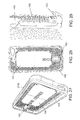
- the replaceable cover 106 has multiple ports for different components of the mobile device such as camera port 108 , headphone port 110 , volume changer port 114 , power port 116 , microphone port 118 , and speaker port 120 . It should be obvious to one of ordinary skill in the art that any variety of combination of ports can be placed in replaceable cover 106 depending upon the configuration of the inserted device.
- replaceable cover 106 can be modified to accommodate the needs of the user. For example, if a user is using replaceable cover 106 in sports, replaceable cover 106 may be formed from a thick, elastic material to better protect the inserted mobile device. In another instance, a user may desire a thin replaceable cover 106 more suitable for urban environments and frequent use.
- replaceable cover 106 comprises a plurality of cooling holes 122 for preventing the mobile device from overheating when placed in replaceable cover 106 .
- cooling holes 122 can be omitted from replaceable cover 106 if the mobile device is user in, for example, a wet or damp environment.
- Replaceable cover 106 further comprises core recess 124 and belt connector recess 126 which are sized to accommodate core 104 and belt connector 102 , respectively, when placed therein.
- An alternate perspective view of replaceable cover 106 showing core recess 124 and belt connector recess 126 are depicted in FIG. 2 .
- core recess 124 and belt connector recess 126 are contiguous.
- core recess 124 is substantially the same depth as the thickness of multifunction core 104 .
- Core recess 124 may further comprise an extension to allow the multifunction core 104 to be easily removable from core recess 124 using a finger.
- Replaceable cover 106 also preferably comprises light port 128 within core recess 124 .
- multifunction core 104 preferably has a lighting element that can be seen through light port 128 when the lighting element is illuminated.
- a view of replaceable cover 106 from the rear showing light port 128 is depicted in FIG. 3 .
- Replaceable cover 106 further comprises mobile device recess 130 which is located on top of and surrounds core recess 124 .
- Mobile device recess 130 is sized to snugly accommodate a specific mobile device therein.
- Replaceable cover 106 further comprises lip 132 around the edge of replaceable cover 106 which secures a mobile device when placed therein as is known in the art.
- belt connector 102 generally comprises core connector 402 mobile device connector 404 which are coupled together via flexible belt 406 .
- belt connector 102 allows multifunction core 104 to communicate with a mobile device as will be described later.
- Belt connector 102 has appropriate dimensions so that it snugly fits in belt connector recess 126 . Further, belt connector 102 may be manufactured in different lengths and widths to fit a large variety of mobile devices.
- Core connector 402 may utilize any type of male or female connector shape.
- suitable connectors for core connectors 402 include USB A-Type, USB B-Type, USB C-Type, Micro-USB A, Micro-USB B, Micro-USB C, Micro USB ABC, USB Mini-b (4 or 5 pin), USB 3.0 A-Type, USB 3.0 B-Type, and USB 3.0 Micro B, 30-pin Apple® connector, or an Apple® LightningTM Connector.
- core connector 402 may utilize a proprietary male connector shape in order to inhibit other third-party competitors from designing products to be utilized with belt connector 102 and multifunction core 104 .
- the connector type for mobile device connector 404 is chosen to be a male port to properly mate with the female data connection/charging port of the attached mobile device.
- core connector 402 may utilize the same type of connector whereas the connector type for mobile device connector 404 will vary based upon the type of mobile device to be connected. This arrangement allows the multifunction core 104 to be used with a wide variety of mobile devices as will be explained later.
- multifunction core 104 is generally rectangular in shape and comprises belt connection port 602 which mates with core connector 402 as will be shown later.
- Multifunction core 104 is preferably between 20 mm to 60 mm wide and between 20 mm and 125 mm long. However, it should be obvious that the dimensions of multifunction core 104 are not limited to these ranges.
- Multifunction core 104 also comprises memory card reader 604 which allows a memory card to be inserted into multifunction core 104 to provide additional memory or have a chip base memory embedded into the core PCBA board.
- Memory card reader 604 can accept a single memory card or multiple memory cards depending upon the capabilities of memory card reader 604 . Further, permanent memory can also be embedded in multifunction core 104 which is not removable.
- Multifunction core 104 also preferably includes a charging port 606 which can be used for charging core 606 using a custom charger or a docking port.
- FIGS. 7A and 7B depict a rear view of multifunction core 104 showing additional features.
- Multifunction core 104 preferably comprises charging port 702 and lighting element 704 .
- Charging port 702 can be used to simultaneously charge multifunction core 104 and any attached mobile device.
- Replaceable cover 106 is designed such that lighting element 704 aligns with light port 128 when the core is inserted into replaceable cover 106 .
- replaceable cover 106 may also comprise a port corresponding to the location of charging port 702 so that the charging port 702 can be accessed.
- multifunction core 104 may also comprise a speaker (not shown) and a corresponding port on replaceable cover 106 so that emitted sound is not distorted.
- Lighting element 704 is preferably a 1′′ smart LED panel constructed from a PCBA board with 1 to 100 LED diodes.
- the smart LED panel is a low consumption thin (preferably around 2 mm) light emitter that uses less energy than LED diodes.
- LED diodes can also be used.
- Lighting element 702 has many possible uses which include providing light for taking photos and video in low light, functioning as a flashlight, and functioning as a music equalizer, and emergency light strobe. These features of lighting element 704 are controlled via a mobile application on the mobile device or a physical embedded button that will be described in more detail later.
- FIGS. 8A and 8B depict an exploded view of multifunction core 104 showing some of the internal components not viewable in FIG. 6, 7A , or 7 B.
- Multifunction core 104 preferably further comprises battery 802 and wireless charger 804 .
- lighting element 704 is viewable through core port 806 .
- Lighting element 704 , battery 802 , and wireless charger 804 are sealed inside of multifunction core 104 using cover 808 .
- cover 808 could be removable to allow a user to replace internal components such as battery 802 .
- Battery 802 is preferably a 500 mAh-4000 mAh battery that provides additional battery life to the attached mobile device.
- Wireless charger 804 is preferably an electromagnetic or RF base wireless charging element such as a Qi charger or any other brand which enables wireless charging of both battery 802 and the mobile device using a wireless power transmission pad.
- multifunction core 104 could also comprise an RFID chip or an NFC chip to allow for mobile payments.
- multifunction core 104 may comprise an IR blaster to allow multifunction core 104 to act as a remote control.
- multifunction core 104 may comprise of a chip base camera, humidity sensor, temperature sensor, pressure sensor, measurement sensor, teaser electric pulse module, and any other sensor base module.
- Cover 808 may additionally comprise tab 810 which allows multifunction core 104 to easily be removed from core recess 124 by using a single finger.
- FIG. 9 The connection of belt connector 102 to multifunction core 104 is depicted in FIG. 9 .
- core connector 402 is mated with belt connection port 602 .
- the connected devices can then be placed into replaceable cover 106 as depicted in FIGS. 10 and 11 .
- a mobile device can be connected to mobile device connector 404 and secured within replaceable cover 106 using lip 132 . Because the mobile device rests on top of multifunction core 104 , the mobile device also secures multifunction core 104 within replaceable cover 106 .
- FIGS. 12A and 12B The connection of multifunction core 104 to mobile device 1202 using belt connector 102 is depicted in FIGS. 12A and 12B outside of replaceable cover 102 for clarity. As depicted, mobile device connector 404 mates with the charging/data port of the mobile device 1202 .
- FIG. 13 A rear view of expandable cover 106 after insertion of multifunction core 104 and mobile device 1202 is depicted in FIG. 13 .
- lighting element 704 is viewable through light port 128 and the camera of mobile device 1202 is viewable through camera port 108 .
- the volume keys and power button of mobile device 1202 are visible/usable through volume change port 114 and power port 116 , respectively.
- FIGS. 15A-15F Further replaceable covers compatible with the same multifunction core 104 are depicted in FIGS. 15A-15F .
- the replaceable cover 106 depicted in FIG. 15A is compatible with any tablet, such as an iPadTM or an AndroidTM based tablet.
- the replaceable cover 106 comprises all of the appropriate ports for the tablet and a recess for multifunction peripheral 104 and a belt connector 102 compatible with the tablet.
- the replaceable covers depicted in FIGS. 15B and 15C are compatible with different sized phones/tablets which have different features and dimensions.
- the same multifunction core 104 can be used in each of these covers in combination with a different size belt connector 102 .
- multifunction core 104 This enables a user to use the same multifunction core 104 with a wide variety of mobile devices 1202 (e.g., tablets, cellular phones, laptops, etc.). Also, because the multifunction core 104 and the belt connector 102 are not integrally formed with replaceable cover 106 , a user can easily change the replaceable cover (e.g., made of different materials or colors) without having to replace the multifunction core 104 .
- the replaceable cover 106 can also be produced much more cheaply than other covers because there are no integrated electronics.
- belt connector 102 , multifunction core 104 , and replaceable cover 106 can all be sold separately as different components or integrated into a kit for retail. This provides much greater flexibility for both the consumer and the retailer. For example, a user that owns both a tablet and a cellular telephone can purchase a single multifunction core 104 , two belt connectors 102 , and two replaceable covers 106 . The user can then swap the single multifunction core 104 between the tablet and the cellular telephone. However, a device that is a heavy power user may opt to buy a multifunction core 104 for both the tablet and the cellular telephone. It should be apparent to one of ordinary skill in the art the many advantages of this increased flexibility.
- belt connector 102 , multifunction core 104 , and replaceable cover 106 are produced at the same facility since they are not integrated. This allows the manufacturer greater flexibility in choosing where belt connector 102 , multifunction core 104 , and replaceable cover 106 are produced. For example, the manufacturer could have the replaceable covers 106 produced at a factory that specializes in cell phone cases whereas the production of the multifunction core 104 can be accomplished by an electronics factory. This is particularly advantageous because in the current market there are very few facilities that would be able to manufacture belt connector 102 , multifunction core 104 , and replaceable cover 106 .
- Belt connector 102 comprises verification circuit 1602 which connects mobile device 1202 to multifunction core 104 only if mobile device connector 404 is a valid connector. Thus, verification circuit 1602 prevents knockoff belt connectors 102 from being made.
- belt connector 102 may, in some embodiments, comprise core verification circuit 1604 which verifies that the multifunction core 104 connected to core connector 402 is a valid and approved multifunction core.
- core verification circuit may request an encrypted message or code from multifunction core 104 upon connection to verify the attached multifunction core 104 .
- FIG. 17 depicts a schematic diagram of the components of multifunction core 104 .
- verification data store in memory 1706 is transmitted to core verification circuit 1604 for verification. If the multifunction core 104 is verified, connection is established between multifunction core 104 and mobile device 1202 . If multifunction core 104 does not recognize mobile device 1202 , CPU 1704 first detects the operating system installed on mobile device 1202 and then transmits a link or data to mobile device 1202 . This causes a screen to pop-up on mobile device 1202 which allows a user to download application program 1702 .
- the application program 1702 notifies the CPU 1704 that the application program has been installed. As a result, CPU 1704 adds identification data for mobile device 1702 to memory 1706 . This process is repeated for every mobile device that has not been previously attached to multifunction core 104 .
- a user of mobile device 1202 can use the application program 1702 to control any of the peripherals located within multifunction core 104 .
- the application program 1702 can be used to cause a speaker on multifunction core 104 to emit music.
- Application program 1702 can also be used to alter system functions such as picture taking.
- application program 1702 can be programmed to cause lighting element 704 to flash every time mobile device 1202 takes a picture.
- Multifunction core 104 may alternately comprise one or more physical buttons which can be used to interact with the multifunction core 104 instead of the application program 1702 .
- Application program 1702 also provides an interface which allows a user to browse files stored on a memory card inserted into memory card reader 604 using a file browser or to view the status of the charge on battery 802 or the connectivity of wireless charger 804 .
- application program 1702 can be used to prevent battery 802 from charging mobile device 1202 if additional battery power is not needed.
- FIGS. 18-30 depict alternate views of belt connector 102 , multifunction core 104 , and replaceable cover 106 .
- multifunction core 104 is depicted with sample branding along the bottom.
- FIG. 19 shows a front view of an alternate embodiment of replaceable cover 106
- FIG. 20 depicts a perspective view of an alternate embodiment of belt connector 102 .
- multifunction core 104 comprises memory card slots 2102 for accommodating memory cards 2104 .
- Memory cards 104 may be any type of commercially available memory, such as SD cards or mini-SD cards which utilize flash memory.
- multifunction core 104 may have any number of memory card slots 2102 located anywhere on multifunction core 104 .
- removable cover 106 preferably has openings 2702 as shown in FIG. 27 which align with memory card slots 2102 when multifunction core 104 is inserted into replaceable cover 106 .
Landscapes
- Engineering & Computer Science (AREA)
- Computer Networks & Wireless Communication (AREA)
- Signal Processing (AREA)
- Human Computer Interaction (AREA)
- Telephone Set Structure (AREA)
Abstract
Disclosed herein is a multifunction core for use with a wide variety of belt connectors, operating systems, mobile devices, and replaceable cases. The features of the multifunction core are controlled by a dedicated application program installed in the mobile device.
Description
The present invention is a continuation-in-part of U.S. Design application Ser. No. 29/514,035, filed Mar. 26, 2015, the entire content of which is hereby incorporated by reference in its entirety.
The present invention relates to a multifunction peripheral device that can be used with a wide variety of connectors, cases, and mobile devices in an interchangeable manner.
There are currently a wide variety of cases and peripheral devices design to be used with mobile devices. In many instances, the peripheral devices, such as memory, batteries and any other external feature such as sensors accessories of any kind are integrated and built into the case and are not removable. Thus, if the design of the mobile device changes or if a user purchases a different mobile device, the user must purchase a new case if the user desires to have the same functionality. Also, if the peripheral device integrated into the case fails or is otherwise damaged, the user must purchase an entirely new case because the peripheral device is not user replaceable.
Some cases allow users to replace certain peripherals in cases such as batteries. However, these cases typically only have peripherals that have a single function, such as a replaceable battery or replaceable memory. Also, such cases suffer the same limitations as other cases because the connector to the peripheral device is integrated into the case which may significantly increase the cost of the case itself and the ability to only repair or replace the malfunctioning feature.
Thus, there clearly exists a need for a multifunction peripheral device which can be used with a wide variety of replaceable cases with different designs and shapes for different phone brands styles and tablets, connectors, mobile devices, and operating systems. Such a system would allow a user to utilize the multifunction peripheral device along with any combination of cases, connectors, operating systems, and mobile devices without requiring replacement of the multifunction peripheral device without great cost to the user.
The present invention provides a multifunction core for use with a wide variety of belt connectors, operating systems, mobile devices, and replaceable cases. The features of the multifunction core are controlled by a dedicated application program installed in the mobile device.
In the embodiment depicted in FIG. 1 , replaceable cover 106 comprises a plurality of cooling holes 122 for preventing the mobile device from overheating when placed in replaceable cover 106. However, it should be obvious to one of ordinary skill in the art that cooling holes 122 can be omitted from replaceable cover 106 if the mobile device is user in, for example, a wet or damp environment.
Enhanced perspective views of belt connector 102 are depicted in FIGS. 4 and 5 . As shown, belt connector 102 generally comprises core connector 402 mobile device connector 404 which are coupled together via flexible belt 406. Generally, belt connector 102 allows multifunction core 104 to communicate with a mobile device as will be described later. Belt connector 102 has appropriate dimensions so that it snugly fits in belt connector recess 126. Further, belt connector 102 may be manufactured in different lengths and widths to fit a large variety of mobile devices.
In some embodiments, core connector 402 may utilize a proprietary male connector shape in order to inhibit other third-party competitors from designing products to be utilized with belt connector 102 and multifunction core 104.
The connector type for mobile device connector 404 is chosen to be a male port to properly mate with the female data connection/charging port of the attached mobile device. Thus, in a preferred embodiment, core connector 402 may utilize the same type of connector whereas the connector type for mobile device connector 404 will vary based upon the type of mobile device to be connected. This arrangement allows the multifunction core 104 to be used with a wide variety of mobile devices as will be explained later.
A front perspective view of multifunction core 104 is depicted in FIG. 6 . As shown, multifunction core 104 is generally rectangular in shape and comprises belt connection port 602 which mates with core connector 402 as will be shown later. Multifunction core 104 is preferably between 20 mm to 60 mm wide and between 20 mm and 125 mm long. However, it should be obvious that the dimensions of multifunction core 104 are not limited to these ranges.
It should be obvious to one of ordinary skill in the art that various other peripheral devices can also be incorporated into multifunction core 104. For example, multifunction core 104 could also comprise an RFID chip or an NFC chip to allow for mobile payments. In another example, multifunction core 104 may comprise an IR blaster to allow multifunction core 104 to act as a remote control. In another example, multifunction core 104 may comprise of a chip base camera, humidity sensor, temperature sensor, pressure sensor, measurement sensor, teaser electric pulse module, and any other sensor base module.
Cover 808 may additionally comprise tab 810 which allows multifunction core 104 to easily be removed from core recess 124 by using a single finger.
The connection of belt connector 102 to multifunction core 104 is depicted in FIG. 9 . As shown, core connector 402 is mated with belt connection port 602. The connected devices can then be placed into replaceable cover 106 as depicted in FIGS. 10 and 11 . A mobile device can be connected to mobile device connector 404 and secured within replaceable cover 106 using lip 132. Because the mobile device rests on top of multifunction core 104, the mobile device also secures multifunction core 104 within replaceable cover 106.
The connection of multifunction core 104 to mobile device 1202 using belt connector 102 is depicted in FIGS. 12A and 12B outside of replaceable cover 102 for clarity. As depicted, mobile device connector 404 mates with the charging/data port of the mobile device 1202.
A rear view of expandable cover 106 after insertion of multifunction core 104 and mobile device 1202 is depicted in FIG. 13 . As shown, lighting element 704 is viewable through light port 128 and the camera of mobile device 1202 is viewable through camera port 108. Similarly, as depicted in FIG. 14 , the volume keys and power button of mobile device 1202 are visible/usable through volume change port 114 and power port 116, respectively.
Further replaceable covers compatible with the same multifunction core 104 are depicted in FIGS. 15A-15F . For example, the replaceable cover 106 depicted in FIG. 15A is compatible with any tablet, such as an iPad™ or an Android™ based tablet. The replaceable cover 106 comprises all of the appropriate ports for the tablet and a recess for multifunction peripheral 104 and a belt connector 102 compatible with the tablet. The replaceable covers depicted in FIGS. 15B and 15C are compatible with different sized phones/tablets which have different features and dimensions. However, it should be noted that the same multifunction core 104 can be used in each of these covers in combination with a different size belt connector 102. This enables a user to use the same multifunction core 104 with a wide variety of mobile devices 1202 (e.g., tablets, cellular phones, laptops, etc.). Also, because the multifunction core 104 and the belt connector 102 are not integrally formed with replaceable cover 106, a user can easily change the replaceable cover (e.g., made of different materials or colors) without having to replace the multifunction core 104. The replaceable cover 106 can also be produced much more cheaply than other covers because there are no integrated electronics.
Another advantage that the present invention provides is that belt connector 102, multifunction core 104, and replaceable cover 106 can all be sold separately as different components or integrated into a kit for retail. This provides much greater flexibility for both the consumer and the retailer. For example, a user that owns both a tablet and a cellular telephone can purchase a single multifunction core 104, two belt connectors 102, and two replaceable covers 106. The user can then swap the single multifunction core 104 between the tablet and the cellular telephone. However, a device that is a heavy power user may opt to buy a multifunction core 104 for both the tablet and the cellular telephone. It should be apparent to one of ordinary skill in the art the many advantages of this increased flexibility.
An additional benefit to the producer of belt connector 102, multifunction core 104, and replaceable cover 106 is that they do not have to be made at the same facility since they are not integrated. This allows the manufacturer greater flexibility in choosing where belt connector 102, multifunction core 104, and replaceable cover 106 are produced. For example, the manufacturer could have the replaceable covers 106 produced at a factory that specializes in cell phone cases whereas the production of the multifunction core 104 can be accomplished by an electronics factory. This is particularly advantageous because in the current market there are very few facilities that would be able to manufacture belt connector 102, multifunction core 104, and replaceable cover 106.
The additional features and functionality that multifunction core 104 and belt connector 102 provide to mobile device 102 will be explained with reference to the following block diagrams. First, referring to FIG. 16 , depicted is a block diagram showing the functionality provided by belt connector 102. Belt connector 102 comprises verification circuit 1602 which connects mobile device 1202 to multifunction core 104 only if mobile device connector 404 is a valid connector. Thus, verification circuit 1602 prevents knockoff belt connectors 102 from being made.
Similarly, belt connector 102 may, in some embodiments, comprise core verification circuit 1604 which verifies that the multifunction core 104 connected to core connector 402 is a valid and approved multifunction core. For example, core verification circuit may request an encrypted message or code from multifunction core 104 upon connection to verify the attached multifunction core 104.
Once a user of the mobile device downloads and installs the appropriate application program 1702, the application program 1702 notifies the CPU 1704 that the application program has been installed. As a result, CPU 1704 adds identification data for mobile device 1702 to memory 1706. This process is repeated for every mobile device that has not been previously attached to multifunction core 104.
A user of mobile device 1202 can use the application program 1702 to control any of the peripherals located within multifunction core 104. For example, the application program 1702 can be used to cause a speaker on multifunction core 104 to emit music. Application program 1702 can also be used to alter system functions such as picture taking. For example, application program 1702 can be programmed to cause lighting element 704 to flash every time mobile device 1202 takes a picture. Multifunction core 104 may alternately comprise one or more physical buttons which can be used to interact with the multifunction core 104 instead of the application program 1702.
In order to accommodate the insertion and removable of memory cards 2104, removable cover 106 preferably has openings 2702 as shown in FIG. 27 which align with memory card slots 2102 when multifunction core 104 is inserted into replaceable cover 106.
Claims (15)
1. A multifunction core for use with a mobile device comprising:
a plurality of peripheral devices integrated into a body of the multifunction core;
a memory device integrated into the body of the multifunction core;
an identification circuit for identifying if an attached external device has previously been connected to the multifunction core, wherein, if the identification circuit determines that the attached external device is unrecognized, the identification circuit identifies the operating system of the attached external device, and sends data or a link to the attached external device to allow a user to download and install an application program for controlling the memory device and the plurality of peripheral devices;
at least one battery integrated into the body of the multifunction core; and
at least one connection port for connecting the multifunction core to an external device via a belt connector,
wherein the connection port supplies power or transfers data to the external device through the belt connector.
2. The multifunction core according to claim 1 , wherein the plurality of peripheral devices are chosen from the group consisting of a wireless charger, an IR blaster, a speaker, and a lighting element.
3. The multifunction core according to claim 2 , wherein the lighting element is a smart LED panel constructed from a PCBA board having 1 to 100 LED diodes.
4. The multifunction core according to claim 1 , wherein the memory device is a memory card reader, a memory card, or a chip based memory.
5. The multifunction core according to claim 1 , wherein the memory card reader comprises inputs for multiple memory cards.
6. The multifunction core according to claim 1 , further comprising:
a belt connector identification module for verifying if a belt connector attached to the multifunction core is a valid belt connector, wherein the belt connector identification module prevents transmission of data to the external device if the attached belt connector is not a valid belt connector.
7. The multifunction core according to claim 1 , wherein the wireless charger recharges the battery and the attached mobile device when the wireless charger is placed within a predetermined distance of a wireless charging pad.
8. The multifunction core according to claim 1 , further comprising:
a charging port for connecting the multifunction core to an external power supply, wherein the charging support supplies power to the battery and to the mobile device.
9. A kit for protecting and providing multifunction capabilities to a mobile device, the system comprising:
a multifunction core comprising a plurality of peripheral devices into a core body, a belt connector having a core connector, a flexible belt, and a mobile device connector; and
at least one cover, wherein the cover further comprises:
a core recess for allowing the multifunction core to be placed snugly therein, wherein a depth of the core recess is the same as or greater than a thickness of the multifunction core;
a belt connector recess for accommodating the belt connector when core connector is attached to a connection port of the multifunction core, wherein the belt connector recess is located adjacent to the core recess, and wherein a depth of the belt connector recess is the same as the depth of the depth of the core recess; and
a mobile device recess for accommodating the mobile device, wherein the mobile device recess comprises a lip around its periphery for retaining the mobile device within the cover.
10. The kit according to claim 9 , wherein the mobile device recess is located above the core recess, and wherein the mobile device secures the multifunction core within the core recess when the mobile device is placed into the mobile device recess.
11. The kit according to claim 9 , wherein the core recess comprises a plurality of ports which align with the peripheral devices of the multifunction core.
12. The kit according to claim 9 , wherein the mobile device recess comprises a plurality of ports which align with inputs and outputs of the mobile device.
13. The kit according to claim 9 , wherein the multifunction core is the same size as the mobile device, or smaller than the mobile device.
14. The kit according to claim 9 , wherein the core connector is a proprietary connector and the mobile device connector is an industry standard connector.
15. The kit according to claim 9 , wherein the body of the multifunction core comprises a tab extending from an edge of the body and the multifunction core; and
the core recess comprises a tab recess greater in size than the tab, wherein a user can use a finger to remove the multifunction core from the core recess using the tab.
Priority Applications (3)
| Application Number | Priority Date | Filing Date | Title |
|---|---|---|---|
| US14/938,505 US9826079B2 (en) | 2015-03-26 | 2015-11-11 | Multifunction peripheral device with interchangeable connectors and casts for mobile devices |
| PCT/US2016/061233 WO2017083460A1 (en) | 2015-11-11 | 2016-11-10 | Multifunctionional cases for mobile devices |
| US15/672,613 US11223459B2 (en) | 2009-02-10 | 2017-08-09 | Mapping user data onto a time-frequency resource grid in a coordinated multi-point wireless communication system |
Applications Claiming Priority (2)
| Application Number | Priority Date | Filing Date | Title |
|---|---|---|---|
| US29514035 | 2015-03-26 | ||
| US14/938,505 US9826079B2 (en) | 2015-03-26 | 2015-11-11 | Multifunction peripheral device with interchangeable connectors and casts for mobile devices |
Related Parent Applications (2)
| Application Number | Title | Priority Date | Filing Date |
|---|---|---|---|
| US14/341,941 Continuation US9215053B2 (en) | 2009-02-10 | 2014-07-28 | Mapping user data onto a time-frequency resource grid in a coordinated multi-point wireless communication system |
| US29514035 Continuation-In-Part | 2015-03-26 | 2015-03-26 |
Related Child Applications (1)
| Application Number | Title | Priority Date | Filing Date |
|---|---|---|---|
| US15/356,747 Continuation US9762366B2 (en) | 2009-02-10 | 2016-11-21 | Mapping user data onto a time-frequency resource grid in a coordinated multi-point wireless communication system |
Publications (2)
| Publication Number | Publication Date |
|---|---|
| US20160286025A1 US20160286025A1 (en) | 2016-09-29 |
| US9826079B2 true US9826079B2 (en) | 2017-11-21 |
Family
ID=56976051
Family Applications (1)
| Application Number | Title | Priority Date | Filing Date |
|---|---|---|---|
| US14/938,505 Expired - Fee Related US9826079B2 (en) | 2009-02-10 | 2015-11-11 | Multifunction peripheral device with interchangeable connectors and casts for mobile devices |
Country Status (1)
| Country | Link |
|---|---|
| US (1) | US9826079B2 (en) |
Cited By (2)
| Publication number | Priority date | Publication date | Assignee | Title |
|---|---|---|---|---|
| US20230285230A1 (en) * | 2022-01-19 | 2023-09-14 | Raymond Hsu | Housing apparatus of a rechargeable physiotherapy instrument |
| USD1011331S1 (en) * | 2023-05-25 | 2024-01-16 | Liyang Li | Phone case |
Families Citing this family (11)
| Publication number | Priority date | Publication date | Assignee | Title |
|---|---|---|---|---|
| USD821380S1 (en) * | 2015-10-09 | 2018-06-26 | Alliance Sports Group, L.P. | Cover for electronic communications device |
| USD821379S1 (en) * | 2015-10-09 | 2018-06-26 | Alliance Sports Group, L.P. | Cover for electronic communications device |
| USD840988S1 (en) * | 2015-11-13 | 2019-02-19 | Spigen Korea Co., Ltd. | Case for electronic communications device |
| USD839858S1 (en) * | 2015-11-13 | 2019-02-05 | Spigen Korea Co., Ltd. | Case for electronic communications device |
| USD840989S1 (en) * | 2015-11-13 | 2019-02-19 | Spigen Korea Co., Ltd. | Case for electronic communications device |
| USD875089S1 (en) * | 2017-12-28 | 2020-02-11 | Incipio, Llc | Portable electronic device case |
| GB2565765B (en) * | 2017-08-14 | 2019-09-11 | Lidan Ltd | Decorative tablet computer cover |
| KR102041430B1 (en) * | 2017-12-07 | 2019-11-27 | (주)에스피에스 | Smartphone combined external device and external device smartphone combine method |
| USD893468S1 (en) * | 2019-01-17 | 2020-08-18 | Shenzhen Guangyipeng Technology Co., Ltd. | Protective case for a mobile device |
| USD951241S1 (en) | 2020-07-22 | 2022-05-10 | Urban Armor Gear, Llc | Case |
| USD952625S1 (en) * | 2020-07-22 | 2022-05-24 | Urban Armor Gear, Llc | Case |
Citations (13)
| Publication number | Priority date | Publication date | Assignee | Title |
|---|---|---|---|---|
| US20080220752A1 (en) * | 2007-01-07 | 2008-09-11 | Scott Forstall | Portable Multifunction Device, Method, and Graphical User Interface for Managing Communications Received While in a Locked State |
| US20080224659A1 (en) * | 2007-03-14 | 2008-09-18 | Sanjeev Kumar Singh | Hand-held, portable electronic device with retainer port for receiving one or more attachable wireless audiophones for in situ charging |
| US20090130874A1 (en) * | 2007-11-16 | 2009-05-21 | Sony Ericsson Mobile Communications Ab | Multipurpose universal serial bus cable |
| US20110208545A1 (en) * | 2010-02-24 | 2011-08-25 | Kuester Jeffrey R | Portable Device Distraction Reduction System |
| US20120043236A1 (en) * | 2010-08-23 | 2012-02-23 | Peter Szucs | Mobile Device Vessel |
| US20120275025A1 (en) * | 2011-04-29 | 2012-11-01 | Parrill Matthew B | Protective cover for an electronic device |
| US20130270002A1 (en) * | 2012-04-15 | 2013-10-17 | Jonathan Eric Fawcett | Charge and sync cables for mobile devices |
| US20140304529A1 (en) * | 2013-04-08 | 2014-10-09 | Ford Meazell | System and Method for Battery Power Transfer Between Mobile Devices |
| US20150084769A1 (en) * | 2012-04-24 | 2015-03-26 | Iloc Technologies Inc. | Apparatus and methods for geolocating an individual with respect to a perimeter |
| US20150350147A1 (en) * | 2014-05-31 | 2015-12-03 | Apple Inc. | Displaying interactive notifications on touch sensitive devices |
| US20160041830A1 (en) * | 2013-05-16 | 2016-02-11 | Microsoft Technology Licensing, Llc | Extraction of operating system-specific characteristics via a communication interface |
| US20160192124A1 (en) * | 2013-03-28 | 2016-06-30 | Brother Kogyo Kabushiki Kaisha | Communication Device and Non-Transitory Computer-Readable Recording Medium |
| US20160330327A1 (en) * | 2014-01-06 | 2016-11-10 | Lg Electronics Inc. | Mobile terminal and control method therefor |
-
2015
- 2015-11-11 US US14/938,505 patent/US9826079B2/en not_active Expired - Fee Related
Patent Citations (13)
| Publication number | Priority date | Publication date | Assignee | Title |
|---|---|---|---|---|
| US20080220752A1 (en) * | 2007-01-07 | 2008-09-11 | Scott Forstall | Portable Multifunction Device, Method, and Graphical User Interface for Managing Communications Received While in a Locked State |
| US20080224659A1 (en) * | 2007-03-14 | 2008-09-18 | Sanjeev Kumar Singh | Hand-held, portable electronic device with retainer port for receiving one or more attachable wireless audiophones for in situ charging |
| US20090130874A1 (en) * | 2007-11-16 | 2009-05-21 | Sony Ericsson Mobile Communications Ab | Multipurpose universal serial bus cable |
| US20110208545A1 (en) * | 2010-02-24 | 2011-08-25 | Kuester Jeffrey R | Portable Device Distraction Reduction System |
| US20120043236A1 (en) * | 2010-08-23 | 2012-02-23 | Peter Szucs | Mobile Device Vessel |
| US20120275025A1 (en) * | 2011-04-29 | 2012-11-01 | Parrill Matthew B | Protective cover for an electronic device |
| US20130270002A1 (en) * | 2012-04-15 | 2013-10-17 | Jonathan Eric Fawcett | Charge and sync cables for mobile devices |
| US20150084769A1 (en) * | 2012-04-24 | 2015-03-26 | Iloc Technologies Inc. | Apparatus and methods for geolocating an individual with respect to a perimeter |
| US20160192124A1 (en) * | 2013-03-28 | 2016-06-30 | Brother Kogyo Kabushiki Kaisha | Communication Device and Non-Transitory Computer-Readable Recording Medium |
| US20140304529A1 (en) * | 2013-04-08 | 2014-10-09 | Ford Meazell | System and Method for Battery Power Transfer Between Mobile Devices |
| US20160041830A1 (en) * | 2013-05-16 | 2016-02-11 | Microsoft Technology Licensing, Llc | Extraction of operating system-specific characteristics via a communication interface |
| US20160330327A1 (en) * | 2014-01-06 | 2016-11-10 | Lg Electronics Inc. | Mobile terminal and control method therefor |
| US20150350147A1 (en) * | 2014-05-31 | 2015-12-03 | Apple Inc. | Displaying interactive notifications on touch sensitive devices |
Cited By (3)
| Publication number | Priority date | Publication date | Assignee | Title |
|---|---|---|---|---|
| US20230285230A1 (en) * | 2022-01-19 | 2023-09-14 | Raymond Hsu | Housing apparatus of a rechargeable physiotherapy instrument |
| US11986437B2 (en) * | 2022-01-19 | 2024-05-21 | Raymond Hsu | Housing apparatus of a rechargeable physiotherapy instrument |
| USD1011331S1 (en) * | 2023-05-25 | 2024-01-16 | Liyang Li | Phone case |
Also Published As
| Publication number | Publication date |
|---|---|
| US20160286025A1 (en) | 2016-09-29 |
Similar Documents
| Publication | Publication Date | Title |
|---|---|---|
| US9826079B2 (en) | Multifunction peripheral device with interchangeable connectors and casts for mobile devices | |
| US9965002B2 (en) | Modular tablet case | |
| US7458825B2 (en) | Double-sided USB-compatible plug connector adapted for insertion in either orientation into a USB-compatible receptacle | |
| EP2773086B1 (en) | Electronic device with structure for inserting card type external device | |
| US11481564B2 (en) | Tray device and electronic device having i he same | |
| US11553068B2 (en) | Contact structure and electronic device including same | |
| US20240280943A1 (en) | Electronic device comprising speaker structure | |
| KR102666320B1 (en) | I/o connector and electric device including the same | |
| CN105898061A (en) | Multifunction Peripheral Core Components for Mobile Devices with Replaceable Connectors and Housings | |
| CN205912124U (en) | Multifunctional core component for mobile equipment and matched assembly | |
| US20170070255A1 (en) | Cover set | |
| WO2017083460A1 (en) | Multifunctionional cases for mobile devices | |
| TWM515129U (en) | Intelligent watch having card type expansion module | |
| US11460893B2 (en) | Electronic device including nonmetallic light guide structure | |
| US10488889B2 (en) | Electronic device including component tray | |
| KR200487787Y1 (en) | Smart band having USB memory | |
| US9991926B2 (en) | Cover set | |
| KR102739273B1 (en) | Strap uniting device and wearable electronic device including the same | |
| KR200497166Y1 (en) | Connecting device and auxiliary power supply | |
| KR102510848B1 (en) | Protection Structure for component and electric device including the same | |
| KR20230067340A (en) | Electronic device | |
| CN116745706A (en) | Electronic device and method for manufacturing the same | |
| KR20200038640A (en) | Digital pen and electronic device comprising the same | |
| CN111434092A (en) | Back clip | |
| TWM519263U (en) | Intelligent watch with embedded expansion module |
Legal Events
| Date | Code | Title | Description |
|---|---|---|---|
| STCF | Information on status: patent grant |
Free format text: PATENTED CASE |
|
| FEPP | Fee payment procedure |
Free format text: MAINTENANCE FEE REMINDER MAILED (ORIGINAL EVENT CODE: REM.); ENTITY STATUS OF PATENT OWNER: SMALL ENTITY |
|
| LAPS | Lapse for failure to pay maintenance fees |
Free format text: PATENT EXPIRED FOR FAILURE TO PAY MAINTENANCE FEES (ORIGINAL EVENT CODE: EXP.); ENTITY STATUS OF PATENT OWNER: SMALL ENTITY |
|
| STCH | Information on status: patent discontinuation |
Free format text: PATENT EXPIRED DUE TO NONPAYMENT OF MAINTENANCE FEES UNDER 37 CFR 1.362 |
|
| FP | Lapsed due to failure to pay maintenance fee |
Effective date: 20211121 |