US974770A - Removable rim for vehicle-wheels. - Google Patents
Removable rim for vehicle-wheels. Download PDFInfo
- Publication number
- US974770A US974770A US37573807A US1907375738A US974770A US 974770 A US974770 A US 974770A US 37573807 A US37573807 A US 37573807A US 1907375738 A US1907375738 A US 1907375738A US 974770 A US974770 A US 974770A
- Authority
- US
- United States
- Prior art keywords
- rim
- vehicle
- wheels
- removable rim
- tire
- Prior art date
- Legal status (The legal status is an assumption and is not a legal conclusion. Google has not performed a legal analysis and makes no representation as to the accuracy of the status listed.)
- Expired - Lifetime
Links
Images

Classifications
-
- B—PERFORMING OPERATIONS; TRANSPORTING
- B60—VEHICLES IN GENERAL
- B60B—VEHICLE WHEELS; CASTORS; AXLES FOR WHEELS OR CASTORS; INCREASING WHEEL ADHESION
- B60B23/00—Attaching rim to wheel body
- B60B23/06—Attaching rim to wheel body by screws, bolts, pins, or clips
- B60B23/10—Attaching rim to wheel body by screws, bolts, pins, or clips arranged axially
Definitions
- My present invention relates to improvements in vehicle wheels, larly to the fellies and rims thereof as designed for use in connection with motor vehicles.
- the object of the invention is to provide an extremely simple and eiiicient construction by which an automobilist can carry one or more extra tubes and shoes or cases inflated on extra rims so that in case of. an accident to a tire the rim with its damaged tire may be quickly and easily removed and replaced by the fresh inflated one.
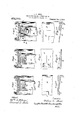
- Figure l is a sectional view through a felly and rim on line 1-1 of Fig. 4. Fi 2 1s a similar section on line 2-2 of Fig. 4.
- Fig. 3 is a like section on line 33 of Fig. 4.
- Fig. 4 is a bottom plan View.
- Figs. 5, 6 and. 7 are detailed plan views of the various parts, on alarger scale.
- Figs. 5, 6 and 7 are sectional details of the parts shown in Figs. 5, 6 and 7, also enlarged.
- the latter A designates the telly of the ordinary motor vehicle or automobile wheel.
- This is encircled by a. permanent rim B which encircles the felly and is socured thereto in any desired manner.
- This rim B has an inclined upper surface 7/ as clearly shown in Fig. 6 and is provided at suitable distances with a. plurality of trans verse grooves b which are designed to receive lugs 0 projecting from the underside of "the rim C which 15 shown for convenience and more particuas an ordinary clencher rim but may be a rim adapted to carry any ordinary or desired form of tire.
- the lugs 0 engaging the transverse grooves b are designed to lock the two together against any circumferential movement.
- I provide a wedge shaped locking ring. D.
- This has at suitable intervals lugs (i, projecting downwardly from its thin edge which are designed to travel in bayonet slots E.
- the transverse portions 6 of the slots permit the ring D to be inserted into the position as shown in Fig. 2, when a slight turn will caus'e'the projections (Z to enter the portions 0 at the bayonet slots, thus affording a firm support for the tire carrying rim.
- I provide a bolt- F which passes through alining openings in the rim Band ring 1), whereby the two are locked together against relative circumferential movement.
- the pin is normally forced into engaging position by a spring G located in a casing H and bearing against a flange or collar iion the pin.
- the pin is provided with a head I outside of the casing by which it may be withdrawn.
- the side of a tire carrying rim may be first put in place, the valve tube of the pneumatic tire being in serted through the usual opening in the rim and felly and then the opposite side of the tire carrying rim swung into position owing to the inclined face 7) of the rim B until the lugs (l all rest agaii-ist the closed ends of the recesses Z) in the position shown in Fig. 1 at which time the locking ring may be readily applied in the manner hereinbefore described, a slot d being provided for the passage of the valve stem.
- VVhat- I claim is: permanent rim, substantially as described. 5 In a vehicle Wheel, a permanent 'rim 'hav- In testimony whereof, I aflix my signature l5 ing an inclined face and transverse grooves in presence of two witnesseses. i in its face, a the carrying rim reinovably ARTHUR NEEDHAMI-IOOD. carried thereby and having lugs engaging VVitnessesz. saidgrooves, said permanent rim having also GEORGE S. VAN Voonins,
Landscapes
- Engineering & Computer Science (AREA)
- Mechanical Engineering (AREA)
- Tires In General (AREA)
Description
A. N. HOOD. REMOVABLE RIM FOB VEHICLE WHEELS.
v APPLICATION FILED MAY 25, 1907. I 9743?, Patented Nov. 1, 1910.
A. N. HOOD. REMOVABLE RIM FOR VEHICLE WHEELS.
- Patented. Nov. 1,1910.
2 SHEETS-SHEET 2.
lnvenian .531 figm 7 Wet APPLICATION FILED MAY 25, 1907.
. al QM x fiz;
- pni rn STATES PATENT ARTHUR NEEDHAM HOOD, OF BOSTON, MASSACHUSETTS, ASSIGNOB "I0 H091) RUBBER COMPANY, OF BOSTON, MASSACHUSETTS, A CORPORATION.
REMOVABLE RIM FOR VEHICLE-WHEELS.
Specification of Letters Patent.
Application filed May 25, 1907. Serial No. 375,738.
To all whom it may concern: 7
Be it known that I, ARTHUR NEEDHAM Hooo, a citizenof the United States, residing at Boston, Massachusetts, have invented certain new and useful Improvements in Removable Rims for Vehicle-VVheels, of which the following is a specification.
My present invention relates to improvements in vehicle wheels, larly to the fellies and rims thereof as designed for use in connection with motor vehicles.
The object of the invention is to provide an extremely simple and eiiicient construction by which an automobilist can carry one or more extra tubes and shoes or cases inflated on extra rims so that in case of. an accident to a tire the rim with its damaged tire may be quickly and easily removed and replaced by the fresh inflated one.
lVith these objects in view the invention comprises the novel features of construction hereinafter described and particularly set forth in the appended claim.
The invention is illustrated in the accompanying drawings, in which,-
Figure l is a sectional view through a felly and rim on line 1-1 of Fig. 4. Fi 2 1s a similar section on line 2-2 of Fig. 4.
Fig. 3 is a like section on line 33 of Fig. 4. Fig. 4 is a bottom plan View. Figs. 5, 6 and. 7 are detailed plan views of the various parts, on alarger scale. Figs. 5, 6 and 7 are sectional details of the parts shown in Figs. 5, 6 and 7, also enlarged.
Referring by reference characters to these figures the latter A designates the telly of the ordinary motor vehicle or automobile wheel. This is encircled by a. permanent rim B which encircles the felly and is socured thereto in any desired manner. This rim B has an inclined upper surface 7/ as clearly shown in Fig. 6 and is provided at suitable distances with a. plurality of trans verse grooves b which are designed to receive lugs 0 projecting from the underside of "the rim C which 15 shown for convenience and more particuas an ordinary clencher rim but may be a rim adapted to carry any ordinary or desired form of tire. The lugs 0 engaging the transverse grooves b are designed to lock the two together against any circumferential movement. In order to fill the V-shaped space left between the inclined surface 6 of the rim B and the inner face of the tire carrying rim C, I provide a wedge shaped locking ring. D. This has at suitable intervals lugs (i, projecting downwardly from its thin edge which are designed to travel in bayonet slots E. The transverse portions 6 of the slots permit the ring D to be inserted into the position as shown in Fig. 2, when a slight turn will caus'e'the projections (Z to enter the portions 0 at the bayonet slots, thus affording a firm support for the tire carrying rim. In order to hold this locking ring D against circumferential movement and thus prevent its accidental unlocking movement, I provide a bolt- F which passes through alining openings in the rim Band ring 1), whereby the two are locked together against relative circumferential movement. The pin is normally forced into engaging position bya spring G located in a casing H and bearing against a flange or collar iion the pin. The pin is provided with a head I outside of the casing by which it may be withdrawn.
By this arrangement the side of a tire carrying rim may be first put in place, the valve tube of the pneumatic tire being in serted through the usual opening in the rim and felly and then the opposite side of the tire carrying rim swung into position owing to the inclined face 7) of the rim B until the lugs (l all rest agaii-ist the closed ends of the recesses Z) in the position shown in Fig. 1 at which time the locking ring may be readily applied in the manner hereinbefore described, a slot d being provided for the passage of the valve stem.
It will be understood, of course, that where an all metal wheel is used the wood felly will be dispensed with and the spokes might be connected directly to the rim B, ing lugs for engaging said bayonet grooves which in this instance would constltute the and means for locking said filling ring felly. v against circumferential movementon the VVhat- I claim is: permanent rim, substantially as described. 5 In a vehicle Wheel, a permanent 'rim 'hav- In testimony whereof, I aflix my signature l5 ing an inclined face and transverse grooves in presence of two Witnesses. i in its face, a the carrying rim reinovably ARTHUR NEEDHAMI-IOOD. carried thereby and having lugs engaging VVitnessesz. saidgrooves, said permanent rim having also GEORGE S. VAN Voonins,
3 10 bayonet slots or grooves, a filling ring hav- JAMES M. SPEAK.
Priority Applications (1)
| Application Number | Priority Date | Filing Date | Title |
|---|---|---|---|
| US37573807A US974770A (en) | 1907-05-25 | 1907-05-25 | Removable rim for vehicle-wheels. |
Applications Claiming Priority (1)
| Application Number | Priority Date | Filing Date | Title |
|---|---|---|---|
| US37573807A US974770A (en) | 1907-05-25 | 1907-05-25 | Removable rim for vehicle-wheels. |
Publications (1)
| Publication Number | Publication Date |
|---|---|
| US974770A true US974770A (en) | 1910-11-01 |
Family
ID=3043148
Family Applications (1)
| Application Number | Title | Priority Date | Filing Date |
|---|---|---|---|
| US37573807A Expired - Lifetime US974770A (en) | 1907-05-25 | 1907-05-25 | Removable rim for vehicle-wheels. |
Country Status (1)
| Country | Link |
|---|---|
| US (1) | US974770A (en) |
-
1907
- 1907-05-25 US US37573807A patent/US974770A/en not_active Expired - Lifetime
Similar Documents
| Publication | Publication Date | Title |
|---|---|---|
| US974770A (en) | Removable rim for vehicle-wheels. | |
| US1403777A (en) | Demountable ring | |
| US1483698A (en) | Automobile rim-securing means | |
| US823454A (en) | Vehicle-wheel. | |
| US864911A (en) | Vehicle-wheel rim. | |
| US764270A (en) | Vehicle-tire. | |
| US1177461A (en) | Vehicle-wheel rim. | |
| US1342622A (en) | Vehicle-wheel | |
| US1086330A (en) | Vehicle-wheel. | |
| US1498369A (en) | Tire mounting | |
| US960983A (en) | Separable rim for vehicle-wheels. | |
| US940602A (en) | Vehicle-wheel rim. | |
| US1427707A (en) | Tire rim | |
| US772209A (en) | Wheel-rim. | |
| US984186A (en) | Rim for automobile-tires. | |
| US854063A (en) | Wheel. | |
| US1244037A (en) | Vehicle-wheel rim. | |
| US925908A (en) | Wheel for road-vehicles. | |
| US1217144A (en) | Demountable rim. | |
| US1031236A (en) | Vehicle wheel-rim. | |
| US1300223A (en) | Demountable rim for wheels of vehicles. | |
| US1391806A (en) | Products | |
| US1359149A (en) | Demountable rim for wheels | |
| US865306A (en) | Means for securing soft-tread tires to rims. | |
| US1022369A (en) | Vehicle-wheel. |