US9714012B1 - Power source element replacement during vehicle operation - Google Patents
Power source element replacement during vehicle operation Download PDFInfo
- Publication number
- US9714012B1 US9714012B1 US15/004,219 US201615004219A US9714012B1 US 9714012 B1 US9714012 B1 US 9714012B1 US 201615004219 A US201615004219 A US 201615004219A US 9714012 B1 US9714012 B1 US 9714012B1
- Authority
- US
- United States
- Prior art keywords
- power source
- vehicle
- replacement
- receptacle
- source element
- Prior art date
- Legal status (The legal status is an assumption and is not a legal conclusion. Google has not performed a legal analysis and makes no representation as to the accuracy of the status listed.)
- Expired - Fee Related
Links
Images


Classifications
-
- B—PERFORMING OPERATIONS; TRANSPORTING
- B60—VEHICLES IN GENERAL
- B60L—PROPULSION OF ELECTRICALLY-PROPELLED VEHICLES; SUPPLYING ELECTRIC POWER FOR AUXILIARY EQUIPMENT OF ELECTRICALLY-PROPELLED VEHICLES; ELECTRODYNAMIC BRAKE SYSTEMS FOR VEHICLES IN GENERAL; MAGNETIC SUSPENSION OR LEVITATION FOR VEHICLES; MONITORING OPERATING VARIABLES OF ELECTRICALLY-PROPELLED VEHICLES; ELECTRIC SAFETY DEVICES FOR ELECTRICALLY-PROPELLED VEHICLES
- B60L53/00—Methods of charging batteries, specially adapted for electric vehicles; Charging stations or on-board charging equipment therefor; Exchange of energy storage elements in electric vehicles
- B60L53/80—Exchanging energy storage elements, e.g. removable batteries
-
- B—PERFORMING OPERATIONS; TRANSPORTING
- B60—VEHICLES IN GENERAL
- B60S—SERVICING, CLEANING, REPAIRING, SUPPORTING, LIFTING, OR MANOEUVRING OF VEHICLES, NOT OTHERWISE PROVIDED FOR
- B60S5/00—Servicing, maintaining, repairing, or refitting of vehicles
- B60S5/06—Supplying batteries to, or removing batteries from, vehicles
-
- B—PERFORMING OPERATIONS; TRANSPORTING
- B60—VEHICLES IN GENERAL
- B60L—PROPULSION OF ELECTRICALLY-PROPELLED VEHICLES; SUPPLYING ELECTRIC POWER FOR AUXILIARY EQUIPMENT OF ELECTRICALLY-PROPELLED VEHICLES; ELECTRODYNAMIC BRAKE SYSTEMS FOR VEHICLES IN GENERAL; MAGNETIC SUSPENSION OR LEVITATION FOR VEHICLES; MONITORING OPERATING VARIABLES OF ELECTRICALLY-PROPELLED VEHICLES; ELECTRIC SAFETY DEVICES FOR ELECTRICALLY-PROPELLED VEHICLES
- B60L50/00—Electric propulsion with power supplied within the vehicle
- B60L50/50—Electric propulsion with power supplied within the vehicle using propulsion power supplied by batteries or fuel cells
- B60L50/60—Electric propulsion with power supplied within the vehicle using propulsion power supplied by batteries or fuel cells using power supplied by batteries
- B60L50/64—Constructional details of batteries specially adapted for electric vehicles
-
- B—PERFORMING OPERATIONS; TRANSPORTING
- B64—AIRCRAFT; AVIATION; COSMONAUTICS
- B64C—AEROPLANES; HELICOPTERS
- B64C39/00—Aircraft not otherwise provided for
- B64C39/02—Aircraft not otherwise provided for characterised by special use
- B64C39/024—Aircraft not otherwise provided for characterised by special use of the remote controlled vehicle type, i.e. RPV
-
- B—PERFORMING OPERATIONS; TRANSPORTING
- B64—AIRCRAFT; AVIATION; COSMONAUTICS
- B64D—EQUIPMENT FOR FITTING IN OR TO AIRCRAFT; FLIGHT SUITS; PARACHUTES; ARRANGEMENT OR MOUNTING OF POWER PLANTS OR PROPULSION TRANSMISSIONS IN AIRCRAFT
- B64D1/00—Dropping, ejecting, releasing or receiving articles, liquids, or the like, in flight
- B64D1/02—Dropping, ejecting, or releasing articles
-
- B—PERFORMING OPERATIONS; TRANSPORTING
- B64—AIRCRAFT; AVIATION; COSMONAUTICS
- B64U—UNMANNED AERIAL VEHICLES [UAV]; EQUIPMENT THEREFOR
- B64U50/00—Propulsion; Power supply
- B64U50/30—Supply or distribution of electrical power
- B64U50/39—Battery swapping
-
- G—PHYSICS
- G05—CONTROLLING; REGULATING
- G05D—SYSTEMS FOR CONTROLLING OR REGULATING NON-ELECTRIC VARIABLES
- G05D1/00—Control of position, course, altitude or attitude of land, water, air or space vehicles, e.g. using automatic pilots
- G05D1/02—Control of position or course in two dimensions
- G05D1/0202—Control of position or course in two dimensions specially adapted to aircraft
-
- G—PHYSICS
- G05—CONTROLLING; REGULATING
- G05D—SYSTEMS FOR CONTROLLING OR REGULATING NON-ELECTRIC VARIABLES
- G05D1/00—Control of position, course, altitude or attitude of land, water, air or space vehicles, e.g. using automatic pilots
- G05D1/02—Control of position or course in two dimensions
- G05D1/021—Control of position or course in two dimensions specially adapted to land vehicles
- G05D1/0276—Control of position or course in two dimensions specially adapted to land vehicles using signals provided by a source external to the vehicle
- G05D1/0278—Control of position or course in two dimensions specially adapted to land vehicles using signals provided by a source external to the vehicle using satellite positioning signals, e.g. GPS
-
- H—ELECTRICITY
- H01—ELECTRIC ELEMENTS
- H01M—PROCESSES OR MEANS, e.g. BATTERIES, FOR THE DIRECT CONVERSION OF CHEMICAL ENERGY INTO ELECTRICAL ENERGY
- H01M10/00—Secondary cells; Manufacture thereof
- H01M10/42—Methods or arrangements for servicing or maintenance of secondary cells or secondary half-cells
- H01M10/4207—Methods or arrangements for servicing or maintenance of secondary cells or secondary half-cells for several batteries or cells simultaneously or sequentially
-
- H—ELECTRICITY
- H01—ELECTRIC ELEMENTS
- H01M—PROCESSES OR MEANS, e.g. BATTERIES, FOR THE DIRECT CONVERSION OF CHEMICAL ENERGY INTO ELECTRICAL ENERGY
- H01M10/00—Secondary cells; Manufacture thereof
- H01M10/42—Methods or arrangements for servicing or maintenance of secondary cells or secondary half-cells
- H01M10/425—Structural combination with electronic components, e.g. electronic circuits integrated to the outside of the casing
-
- H—ELECTRICITY
- H01—ELECTRIC ELEMENTS
- H01M—PROCESSES OR MEANS, e.g. BATTERIES, FOR THE DIRECT CONVERSION OF CHEMICAL ENERGY INTO ELECTRICAL ENERGY
- H01M50/00—Constructional details or processes of manufacture of the non-active parts of electrochemical cells other than fuel cells, e.g. hybrid cells
- H01M50/20—Mountings; Secondary casings or frames; Racks, modules or packs; Suspension devices; Shock absorbers; Transport or carrying devices; Holders
- H01M50/204—Racks, modules or packs for multiple batteries or multiple cells
-
- H—ELECTRICITY
- H01—ELECTRIC ELEMENTS
- H01M—PROCESSES OR MEANS, e.g. BATTERIES, FOR THE DIRECT CONVERSION OF CHEMICAL ENERGY INTO ELECTRICAL ENERGY
- H01M50/00—Constructional details or processes of manufacture of the non-active parts of electrochemical cells other than fuel cells, e.g. hybrid cells
- H01M50/20—Mountings; Secondary casings or frames; Racks, modules or packs; Suspension devices; Shock absorbers; Transport or carrying devices; Holders
- H01M50/249—Mountings; Secondary casings or frames; Racks, modules or packs; Suspension devices; Shock absorbers; Transport or carrying devices; Holders specially adapted for aircraft or vehicles, e.g. cars or trains
-
- B64C2201/128—
-
- B—PERFORMING OPERATIONS; TRANSPORTING
- B64—AIRCRAFT; AVIATION; COSMONAUTICS
- B64U—UNMANNED AERIAL VEHICLES [UAV]; EQUIPMENT THEREFOR
- B64U2101/00—UAVs specially adapted for particular uses or applications
- B64U2101/60—UAVs specially adapted for particular uses or applications for transporting passengers; for transporting goods other than weapons
- B64U2101/64—UAVs specially adapted for particular uses or applications for transporting passengers; for transporting goods other than weapons for parcel delivery or retrieval
-
- H—ELECTRICITY
- H01—ELECTRIC ELEMENTS
- H01M—PROCESSES OR MEANS, e.g. BATTERIES, FOR THE DIRECT CONVERSION OF CHEMICAL ENERGY INTO ELECTRICAL ENERGY
- H01M10/00—Secondary cells; Manufacture thereof
- H01M10/42—Methods or arrangements for servicing or maintenance of secondary cells or secondary half-cells
- H01M10/425—Structural combination with electronic components, e.g. electronic circuits integrated to the outside of the casing
- H01M2010/4271—Battery management systems including electronic circuits, e.g. control of current or voltage to keep battery in healthy state, cell balancing
-
- H—ELECTRICITY
- H01—ELECTRIC ELEMENTS
- H01M—PROCESSES OR MEANS, e.g. BATTERIES, FOR THE DIRECT CONVERSION OF CHEMICAL ENERGY INTO ELECTRICAL ENERGY
- H01M10/00—Secondary cells; Manufacture thereof
- H01M10/42—Methods or arrangements for servicing or maintenance of secondary cells or secondary half-cells
- H01M10/425—Structural combination with electronic components, e.g. electronic circuits integrated to the outside of the casing
- H01M2010/4278—Systems for data transfer from batteries, e.g. transfer of battery parameters to a controller, data transferred between battery controller and main controller
-
- H—ELECTRICITY
- H01—ELECTRIC ELEMENTS
- H01M—PROCESSES OR MEANS, e.g. BATTERIES, FOR THE DIRECT CONVERSION OF CHEMICAL ENERGY INTO ELECTRICAL ENERGY
- H01M2220/00—Batteries for particular applications
- H01M2220/20—Batteries in motive systems, e.g. vehicle, ship, plane
-
- Y—GENERAL TAGGING OF NEW TECHNOLOGICAL DEVELOPMENTS; GENERAL TAGGING OF CROSS-SECTIONAL TECHNOLOGIES SPANNING OVER SEVERAL SECTIONS OF THE IPC; TECHNICAL SUBJECTS COVERED BY FORMER USPC CROSS-REFERENCE ART COLLECTIONS [XRACs] AND DIGESTS
- Y02—TECHNOLOGIES OR APPLICATIONS FOR MITIGATION OR ADAPTATION AGAINST CLIMATE CHANGE
- Y02E—REDUCTION OF GREENHOUSE GAS [GHG] EMISSIONS, RELATED TO ENERGY GENERATION, TRANSMISSION OR DISTRIBUTION
- Y02E60/00—Enabling technologies; Technologies with a potential or indirect contribution to GHG emissions mitigation
- Y02E60/10—Energy storage using batteries
-
- Y—GENERAL TAGGING OF NEW TECHNOLOGICAL DEVELOPMENTS; GENERAL TAGGING OF CROSS-SECTIONAL TECHNOLOGIES SPANNING OVER SEVERAL SECTIONS OF THE IPC; TECHNICAL SUBJECTS COVERED BY FORMER USPC CROSS-REFERENCE ART COLLECTIONS [XRACs] AND DIGESTS
- Y02—TECHNOLOGIES OR APPLICATIONS FOR MITIGATION OR ADAPTATION AGAINST CLIMATE CHANGE
- Y02T—CLIMATE CHANGE MITIGATION TECHNOLOGIES RELATED TO TRANSPORTATION
- Y02T10/00—Road transport of goods or passengers
- Y02T10/60—Other road transportation technologies with climate change mitigation effect
- Y02T10/70—Energy storage systems for electromobility, e.g. batteries
-
- Y—GENERAL TAGGING OF NEW TECHNOLOGICAL DEVELOPMENTS; GENERAL TAGGING OF CROSS-SECTIONAL TECHNOLOGIES SPANNING OVER SEVERAL SECTIONS OF THE IPC; TECHNICAL SUBJECTS COVERED BY FORMER USPC CROSS-REFERENCE ART COLLECTIONS [XRACs] AND DIGESTS
- Y02—TECHNOLOGIES OR APPLICATIONS FOR MITIGATION OR ADAPTATION AGAINST CLIMATE CHANGE
- Y02T—CLIMATE CHANGE MITIGATION TECHNOLOGIES RELATED TO TRANSPORTATION
- Y02T10/00—Road transport of goods or passengers
- Y02T10/60—Other road transportation technologies with climate change mitigation effect
- Y02T10/7072—Electromobility specific charging systems or methods for batteries, ultracapacitors, supercapacitors or double-layer capacitors
-
- Y—GENERAL TAGGING OF NEW TECHNOLOGICAL DEVELOPMENTS; GENERAL TAGGING OF CROSS-SECTIONAL TECHNOLOGIES SPANNING OVER SEVERAL SECTIONS OF THE IPC; TECHNICAL SUBJECTS COVERED BY FORMER USPC CROSS-REFERENCE ART COLLECTIONS [XRACs] AND DIGESTS
- Y02—TECHNOLOGIES OR APPLICATIONS FOR MITIGATION OR ADAPTATION AGAINST CLIMATE CHANGE
- Y02T—CLIMATE CHANGE MITIGATION TECHNOLOGIES RELATED TO TRANSPORTATION
- Y02T90/00—Enabling technologies or technologies with a potential or indirect contribution to GHG emissions mitigation
- Y02T90/10—Technologies relating to charging of electric vehicles
- Y02T90/16—Information or communication technologies improving the operation of electric vehicles
Definitions
- the present invention relates generally to an apparatus for replacing power source elements of a vehicle and in particular to an apparatus and associated method for using a first vehicle to replace power source elements for a second vehicle during operation of both vehicles.
- a first aspect of the invention provides a vehicle power source replacement method comprising: enabling a first vehicle comprising a power source apparatus and a first power source apparatus attached to the first vehicle, wherein the power source apparatus comprises a plurality of power source elements configured to supply power to the first vehicle independently without requiring power supplied by any other power source element of the plurality of power source elements, wherein the first power source apparatus comprises: a first multiple compartment housing comprising a first plurality of receptacles retaining a first plurality of power source elements within the first plurality of receptacles, a controller connected to the first plurality of power source elements, and a communication interface communicatively coupled to the controller; receiving, by the first vehicle, a notification indicating that a second vehicle requires replacement of at least one power source element of a second plurality of power source elements within a second power source apparatus of the second vehicle, wherein the second plurality of power source elements supply power to the second vehicle independently without requiring power supplied by any other power source of the second plurality of power sources; directing
- a second aspect of the invention provides a computer program product, comprising a computer readable hardware storage device storing a computer readable program code, the computer readable program code comprising an algorithm that when executed by a processor implements a vehicle power source replacement method, the method comprising: enabling a first vehicle comprising a power source apparatus and a first power source apparatus attached to the first vehicle, wherein the power source apparatus comprises a plurality of power source elements configured to supply power to the first vehicle independently without requiring power supplied by any other power source element of the plurality of power source elements, wherein the first power source apparatus comprises: a first multiple compartment housing comprising a first plurality of receptacles retaining a first plurality of power source elements within the first plurality of receptacles, a controller connected to the first plurality of power source elements, and a communication interface communicatively coupled to the controller; receiving, by the first vehicle, a notification indicating that a second vehicle requires replacement of at least one power source element of a second plurality of power source elements within
- a third aspect of the invention provides a vehicle power source apparatus comprising: a multiple compartment housing comprising a fixed outer portion and a rotating portion comprising a plurality of receptacles configured to retain power source elements for supplying power to a vehicle, wherein the multiple compartment housing is configured to be physically attached to the vehicle; a plurality of power source elements within the plurality of receptacles; a controller; and a power source replacement mechanism configured to replace, in response to a command from the controller and during operation of the vehicle and an additional vehicle, a power source element from the additional vehicle with a fully charged power source element of the plurality of power source elements of the vehicle.
- the present invention advantageously provides a simple method and associated system capable of supplying power to vehicles.
- FIG. 1 illustrates a system for replacing power source elements in vehicles during operation of the vehicles, in accordance with embodiments of the present invention.
- FIG. 2 illustrates a vehicle power source apparatus enabled by the system of FIG. 1 for accepting replacement power source elements in a vehicle during operation of the vehicle, in accordance with embodiments of the present invention.
- FIG. 3 illustrates a vehicle power source apparatus enabled by the system of FIG. 1 for replacing power source elements in a secondary vehicle during operation of the secondary vehicle, in accordance with embodiments of the present invention.
- FIG. 4 illustrates a flowchart detailing a process enabled by the system of FIG. 1 for replacing power source elements in a vehicle during operation of the vehicle, in accordance with embodiments of the present invention.
- FIG. 5 illustrates a first vehicle docked to a second vehicle for replacement of power source elements, in accordance with embodiments of the present invention.
- FIG. 6 illustrates a power source element residing within a power source capsule, in accordance with embodiments of the present invention.
- FIG. 7 illustrates a power source element/power source capsule, in accordance with embodiments of the present invention.
- FIG. 8 illustrates an alternative power source element/power source capsule, in accordance with embodiments of the present invention.
- FIG. 9 illustrates a computer system used by the system of FIG. 1 for enabling a process for replacing power source elements in a vehicle during operation of the vehicle, in accordance with embodiments of the present invention.
- FIG. 1 illustrates a system 100 for replacing power source elements in a vehicle 14 a during operation of vehicle 14 a , in accordance with embodiments of the present invention.
- System 100 enables a process for utilizing multiple power source elements for 14 a vehicle such that vehicle 14 a includes a multiple compartment housing (e.g., at a center of gravity of the vehicle retaining the multiple power source elements) such that the power source elements may be replaced and exchanged with fully charged power source elements (from a vehicle 14 b ) during operation of the vehicles 14 a and 14 b .
- vehicle 14 a includes a multiple compartment housing (e.g., at a center of gravity of the vehicle retaining the multiple power source elements) such that the power source elements may be replaced and exchanged with fully charged power source elements (from a vehicle 14 b ) during operation of the vehicles 14 a and 14 b .
- Vehicles 14 a and 14 b may each comprise any vehicle that does not require a human operator to be located within the vehicles 14 a and 14 b such as, inter alia, a remote controlled vehicle (e.g., an aircraft flown by a pilot at a ground control station), an autonomously controlled vehicle (e.g., an aircraft controlled based on pre-programmed flight plans and may include an intelligence algorithm that would enable vehicle 14 to know it's location and self-determine a route to join with a second vehicle dynamically), a pre-programmed vehicle, etc.
- a remote controlled vehicle e.g., an aircraft flown by a pilot at a ground control station
- an autonomously controlled vehicle e.g., an aircraft controlled based on pre-programmed flight plans and may include an intelligence algorithm that would enable vehicle 14 to know it's location and self-determine a route to join with a second vehicle dynamically
- a pre-programmed vehicle etc.
- vehicles 14 a and 14 b may comprise any type of vehicle that includes a human operator located within vehicles 14 a and 14 b (e.g., an aircraft, an automobile, a boat or ship, a train, etc.).
- Vehicles 14 a and 14 b may include, inter alia, an aerial vehicle, a land based vehicle, a marine (water) based vehicle, etc.
- Power source elements may include any type of (portable) power source element including, inter alia, a battery, a fuel cell, etc.
- a power source element may comprise a power source (e.g., a battery) placed within a power source capsule (e.g., as illustrated in FIG. 6 ).
- a power source element may comprise a specially shaped power source (e.g., a battery) without the power source capsule.
- System 100 allows vehicle 14 a to utilize a series of power source elements (e.g., power supplies) to power vehicle 14 a for operation.
- System 100 enables vehicle 14 a to draw power (e.g., a direct current voltage) from multiple power source elements that would extend an operational (e.g., flying) time, range, and delivery capacity for vehicle 14 a .
- system 100 enables one or more power source elements (optionally comprising a specified shape) to be used as replacement power source elements (the replacement power source elements may be located in a separate multi compartment housing from a housing retaining power source elements for powering vehicle 14 a as described with respect to FIG. 5 , infra) to replace discharged power source elements of vehicle 14 b during operation of vehicles 14 a and 14 b .
- a power source element may be guided (from a multi compartment housing of vehicle 14 a ) into an open chamber(s) or receptacle(s) in a multiple compartment power source housing of vehicle 14 b .
- a conical power source element shape i.e., tapered on both ends as illustrated in FIG. 6-8 ) enable multiple vehicle in-operation power source element exchange such that when inserting or extracting power source elements under in-operation conditions (e.g., vibrations, wind, inertia, etc.), an opening of a power source receptacle comprise a be greater size than an insertion end of an associated power source element to compensate for in-operation conditions.
- a power source element (or associated housing) may comprise a guide hole design (an alignment mechanism) to allow docking and alignment via a tapered pin (an alignment mechanism) alignment method for compatible units.
- a power source element may comprise any shape such that a housing may encapsulate industry standard power source elements or any newly manufactured power source element designs.
- System 100 of FIG. 1 includes an external system 15 , a vehicle control system 18 , and a GPS system 21 connected through a network to a vehicle 14 a and a vehicle 14 b .
- Vehicle 14 a retrieves/generates GPS coordinates based data (from GPS system 21 ) in response to a determination that vehicle 14 b requires replacement of at least one power source element.
- the GPS coordinates based data are analyzed (by external system 15 ) to determine exact coordinates for vehicle 14 b requiring replacement of at least one power source element.
- Vehicle 14 a and 14 b , external system 15 , control system 18 , and GPS system 21 each may comprise an embedded computer.
- An embedded computer is defined herein as a remotely portable dedicated computer comprising a combination of computer hardware and software (fixed in capability or programmable) specifically designed for executing a specialized function.
- Programmable embedded computers may comprise specialized programming interfaces.
- vehicle 14 a and 14 b , external system 15 , control system 18 , and GPS system 21 may each comprise a specialized hardware device comprising specialized (non-generic) hardware and circuitry (i.e., specialized discrete non-generic analog, digital, and logic based circuitry) for executing a process described with respect to FIG. 4 .
- the specialized discrete non-generic analog, digital, and logic based circuitry may include proprietary specially designed components (e.g., a specialized integrated circuit designed for only implementing an automated process for enabling a process for replacing power source elements in vehicle 14 b during operation of the vehicles 14 a and 14 b .
- Vehicle 14 a includes a memory system 8 a , software 17 a , and dedicated monitoring hardware 19 a (all sensors and associated monitoring hardware for enabling software 17 a to execute a process for replacing power source elements in a vehicle during operation of the vehicle power such as, inter alia, power level detection circuitry, GPS sensors, temperature sensors, pressure sensors, etc.).
- the memory system 8 a may include a single memory system.
- the memory system 8 a may include a plurality of memory systems.
- Vehicle 14 b includes a memory system 8 b , software 17 b , and dedicated monitoring hardware 19 b (all sensors and associated monitoring hardware for enabling software 17 b to execute a process for replacing power source elements in a vehicle during operation of the vehicle power such as, inter alia, power level detection circuitry, GPS sensors, temperature sensors, pressure sensors, etc.).
- the memory system 8 b may include a single memory system.
- the memory system 8 b may include a plurality of memory systems.
- Network 7 may include any type of network including, inter alia, a local area network, (LAN), a wide area network (WAN), the Internet, a wireless network, etc.
- the multiple compartment housings attached to vehicles 14 a and 14 b of system 100 may include power supply strength indicators (presenting a charge level percentage) for each receptacle to determine an order in which power source elements should be replaced or used for replacement (i.e., an order of replacement).
- Each multiple compartment housing may verify each time a power source element is installed (or used for installation) by detecting a power level and maintaining a discharge history for each power source element (e.g., a burn rate) to determine the order of replacement.
- GPS positioning data may be used to determine current location coordinates.
- FIG. 2 illustrates a vehicle power source apparatus 200 enabled by system 100 of FIG. 1 for accepting replacement power source elements in a vehicle during operation of the vehicle, in accordance with embodiments of the present invention.
- Vehicle power source apparatus 200 is associated with vehicle 14 a of FIG. 1 .
- Vehicle power source apparatus 200 comprises a multiple compartment housing 212 (configured to be physically attached to vehicle 14 a of FIG. 1 ), power source elements 202 a . . . 202 n , and control hardware 210 .
- Multiple compartment housing 212 comprises receptacles 201 a . . . 201 n retaining power source elements 202 a . . . 202 n for supplying power to a vehicle (e.g., vehicle 14 a of FIG. 1 ).
- the multiple compartment housing is configured to be physically attached to a vehicle.
- Multiple compartment housing 212 may be positioned above a center mass of a vehicle (e.g., an aircraft) such that it may be attached to a bottom portion of the vehicle thereby preventing interference with moving parts such as propellers.
- Multiple compartment housing 212 may be aligned with a multiple compartment housing of another vehicle (e.g., multiple compartment housing 312 of FIG. 3 comprising replacement power source elements) via alignment holes 205 a . . . 205 n .
- a design of multiple compartment housing 212 enables a distribution of power source elements 202 a . . . 202 n to balance an associated weight such that not every receptacle requires a power source element.
- each power source element (or grouping of power source elements) is configured to supply power to the vehicle independently without requiring power supplied by any other power source element such that power source elements may be replaced during operation of the vehicle.
- Control hardware 210 comprises specialized hardware configured to implement a process for accepting replacement power source elements for a vehicle during operation of the vehicle.
- Control hardware 210 comprises a controller connected to power source elements 202 a . . . 202 n , a communication interface, a charge strength percentage indicator, and a global positioning satellite (GPS) receiver.
- the controller is configured to monitor a power level of each power source element and generate a power level reading for each power level.
- the power level readings may be used to determine an order for replacement of each power source element.
- the order for replacement may be determined based on generated replacement data specifying a replacement history of each power source element. Additionally, the order for replacement may be determined based on generated discharge data specifying a rate of power discharge for each power source element.
- the controller is further configured to determine a replacement requirement action for replacing each power source element based on a remaining power charge level percentage determined from charge level readings for each power source elements.
- the communication interface is communicatively coupled to the controller and an external system (e.g., external system 15 of FIG. 1 ).
- the communication interface is configured to retrieve each power level reading from the controller and transmit each power level reading to the external system. Additionally, the communication interface is configured to transmit a message indicating a replacement requirement action to the external system.
- the charge strength percentage indicators are connected to each power source element in each receptacle to present a current charge level percentage reading for power source element.
- the GPS receiver is communicatively connected to the controller and is configured to receive geographical coordinates from a satellite to determine (based on retrieved geographical coordinates) a current location for vehicle power source apparatus 200 .
- the GPS receiver is further enabled too receive additional geographical coordinates from the satellite to determine a current location for a power source element replacement location for replacing each power source element.
- the current location is determined based on a current location for vehicle power source apparatus 200 and a predicted range for vehicle power source apparatus 200 and the f power source elements with respect to the current location for the power source replacement element.
- the controller may additionally determine an estimated time of arrival for vehicle power source apparatus 200 arriving at a power source replacement location based on the predicted range.
- FIG. 3 illustrates a vehicle power source apparatus 300 enabled by system 100 of FIG. 1 for replacing power source elements in a secondary vehicle during operation of the secondary vehicle, in accordance with embodiments of the present invention.
- Vehicle power source apparatus 300 is associated with vehicle 14 b of FIG. 1 .
- Vehicle power source apparatus 300 comprises a multiple compartment housing 312 (comprising a fixed outer portion 312 a and a rotating inner portion 312 b ), power source elements 302 a . . . 302 n , and control hardware 310 .
- Multiple compartment housing 312 comprises receptacles 301 a . . . 301 n retaining replacement power source elements 202 a . . .
- the multiple compartment housing is configured to be physically attached to a vehicle.
- Multiple compartment housing 312 may be positioned above a center mass of a vehicle (e.g., an aircraft) such that it may be attached to a bottom or top portion of the vehicle thereby preventing interference with moving parts such as propellers.
- Multiple compartment housing 312 may be aligned with a multiple compartment housing of another vehicle (e.g., multiple compartment housing 212 of FIG. 2 comprising power source elements requiring replacement) via alignment holes 305 a . . . 305 n .
- a design of multiple compartment housing 312 enables a distribution of power source elements 302 a . . .
- the power source elements 302 a . . . 302 n are retained within receptacles 301 a . . . 301 n and electrically connected to an input power coupler for electrical connection to the vehicle such that each power source element (or grouping of power source elements) is configured to supply power to the vehicle independently without requiring power supplied by any other power source element such that power source elements may be replaced during operation of the vehicle.
- an additional multiple compartment housing comprising additional power source elements for powering an associated vehicle thereby allowing multiple compartment housing 312 to use power source elements 302 a . . . 302 n for replacement power source elements only.
- Control hardware 310 comprises specialized hardware configured to implement a process for replacing power source elements in a vehicle during operation of the vehicle.
- Control hardware 210 comprises a controller connected to power source elements 202 a . . . 202 n , a communication interface, and a global positioning satellite (GPS) receiver.
- the controller is configured to receive replacement commands and enable a rotation apparatus (e.g., a motor) to rotate rotating inner portion 312 b such that a receptacle of receptacles 301 a . . . 301 n is directly aligned over an additional receptacle (e.g., of receptacles 201 a . . . 201 n of FIG.
- a rotation apparatus e.g., a motor
- the controller is configured to monitor a power level of each power source element and generate a power level reading for each power level.
- the power level readings may be used to specify power source elements to be used as replacements.
- the communication interface is communicatively coupled to control hardware 310 and an external system (e.g., external system 15 of FIG. 1 ).
- the communication interface is configured to retrieve commands and GPS coordinates associated with a vehicle requiring replacement power source elements. Additionally, the communication interface is configured to receive a message indicating a replacement requirement action from the external system.
- the GPS receiver is communicatively connected to the controller and is configured to receive geographical coordinates from a satellite to determine (based on retrieved geographical coordinates) a current location for a vehicle power source apparatus requiring replacement power source elements.
- the GPS receiver is further enabled too receive additional geographical coordinates from the satellite to determine a current location for a power source element replacement location for replacing each power source element.
- the current location is determined based on a current location for a vehicle requiring replacement power source elements and an associated predicted range for power source elements with respect to the current location for the power source replacement element.
- the controller may additionally determine an estimated time of arrival for a vehicle power source apparatus arriving at a power source replacement location based on the predicted range.
- FIG. 4 illustrates a flowchart detailing a process enabled by system 100 of FIG. 1 for replacing power source elements in a vehicle during operation of the vehicle, in accordance with embodiments of the present invention.
- a first vehicle e.g., vehicle 14 b of FIG. 1
- the first vehicle comprises a power source apparatus and a first power source apparatus (e.g., as illustrated in FIG. 5 , infra) attached to the first vehicle.
- the power source apparatus comprises a plurality of power source elements configured to supply power to the first vehicle independently without requiring power supplied by any other power source element.
- the first power source apparatus comprises: a first multiple compartment housing (comprising a first plurality of receptacles retaining a first plurality of power source elements within the first plurality of receptacles), a controller connected to the first plurality of power source elements, and a communication interface communicatively coupled to the controller. Additionally, the first power source apparatus may comprise a rotation apparatus and the first multiple compartment housing may include a rotating portion comprised by the first multiple compartment housing.
- the first vehicle receives a notification indicating that a second vehicle (e.g., vehicle 14 a of FIG. 1 ) requires replacement of at least one power source element within a second power source apparatus of the second vehicle.
- the second power source apparatus comprises a second multiple compartment housing comprising a second plurality of receptacles retaining the second plurality of power sources within the second plurality of receptacles.
- the second plurality of power source elements supply power to the second vehicle independently without requiring power supplied by any other power source element.
- the controller directs (in response to the notification) the first vehicle to a current location of the second vehicle.
- the first vehicle is docked to the second vehicle.
- the docking process may include:
- the controller determines (based on a received determined power level reading of the at least one power source element of the second vehicle, replacement data specifying a replacement history of the second plurality of power source elements, and discharge data specifying a rate of power discharge for each of the second plurality of power source elements) an order for replacement for the at least one power source element of the second vehicle with respect to each of the second plurality of power source elements.
- the at least one power source element of second vehicle is replaced (during operation of the first vehicle and the second vehicle) with a fully charged power source element of the first plurality of power source elements from the first vehicle.
- the replacement process may include:
- the replacement receptacle includes the fully charged power source element. 5. Transferring (by the power source replacement mechanism) the fully charged power source element from the replacement receptacle to the second receptacle.
- step 414 the first vehicle is undocked from the second vehicle during operation of the first vehicle and the second vehicle.
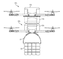
- FIG. 5 illustrates a vehicle 500 a (i.e., representing vehicle 14 b of FIG. 1 ) docked to a vehicle 500 b (i.e., representing vehicle 14 a of FIG. 1 ), in accordance with embodiments of the present invention.
- Vehicle 500 a comprises an attached vehicle power source apparatus 505 a and an attached vehicle power source apparatus 505 b enabled by system 100 of FIG. 1 for replacing power source elements in vehicle 500 b during operation (e.g., during flight) of vehicles 500 a and 500 b .
- Vehicle power source apparatus 505 a comprises power source element(s) for supplying power for operation to vehicle 500 a .
- Vehicle power source apparatus 505 a comprises power source element(s) for supplying fully charged power source elements to vehicle 500 b .
- Vehicle 500 b comprises an attached vehicle power source apparatus 505 c for supplying power for operation to vehicle 500 b .
- Attached vehicle power source apparatus 505 c is configured to receive fully charged power source elements from vehicle power source apparatus 505 b .
- Vehicle 400 comprises a retaining mechanism 507 for retaining a package 508 for delivery.
- FIG. 6 illustrates a configuration comprising a power source element 602 residing within a power source capsule 600 , in accordance with embodiments of the present invention.
- Power source element 602 may comprise any type of battery residing in a power source capsule 600 .
- power source element 602 and a power source capsule 600 in combination may comprise a single power source element or battery.
- Power source capsule 600 is configured to be placed within a receptacle of a multiple compartment housing (e.g., receptacle 201 a of multiple compartment housing 212 of FIG. 2 or receptacle 301 a of multiple compartment housing 312 of FIG. 3 ).
- Power source capsule 600 may comprise a visual indicator 621 (e.g., a lamp, an LED, etc.) indicting that power source element 602 is discharged and requires replacement.
- Power source capsule 600 may comprise a first portion 608 electro-magnetically or mechanically connected (at seam 610 ) to a second portion 611 such that first portion 608 may be raised from second portion 611 to allow for access to/replacement of power source element 602 .
- a canonical (or any specialized) shape i.e., as illustrated in FIG. 6 ) of power source capsule 600 (or a power source element itself) may facilitate replacement during operation of a vehicle (e.g., in flight).
- the specialized shape enables easy replacement of power source capsule 600 by eliminating issues associated with wind, vibrations, etc.
- Power source capsule 600 may be locked into place within a receptacle and a seal (e.g., an O-ring) may be used to create a weather-proof seal when power source capsule 600 is locked into place.
- FIG. 7 illustrates a power source element/power source capsule 700 , in accordance with embodiments of the present invention.
- Power source element/power source capsule 700 comprises mechanical actuators 704 a and 704 b for retrieving or removing power source element/power source capsule 700 from an associated receptacle for replacement.
- Mechanical actuators 704 a and 704 b may comprise, inter alia, a piston mechanism for automatically moving power source element/power source capsule 700 in directions 721 for replacement.
- FIG. 9 illustrates a computer system 90 (e.g., external system 15 , vehicle control system 18 , GPS system 21 , vehicle 14 a , and vehicle 14 b of FIG. 1 ) used by or comprised by the system of FIG. 1 for enabling a process for replacing power source elements in vehicles during operation of vehicles 14 , in accordance with embodiments of the present invention.
- a computer system 90 e.g., external system 15 , vehicle control system 18 , GPS system 21 , vehicle 14 a , and vehicle 14 b of FIG. 1 .
- aspects of the present invention may take the form of an entirely hardware embodiment, an entirely software embodiment (including firmware, resident software, microcode, etc.) or an embodiment combining software and hardware aspects that may all generally be referred to herein as a “circuit,” “module,” or “system.”
- the present invention may be a system, a method, and/or a computer program product.
- the computer program product may include a computer readable storage medium (or media) having computer readable program instructions thereon for causing a processor to carry out aspects of the present invention.
- the computer readable storage medium can be a tangible device that can retain and store instructions for use by an instruction execution device.
- the computer readable storage medium may be, for example, but is not limited to, an electronic storage device, a magnetic storage device, an optical storage device, an electromagnetic storage device, a semiconductor storage device, or any suitable combination of the foregoing.
- a non-exhaustive list of more specific examples of the computer readable storage medium includes the following: a portable computer diskette, a hard disk, a random access memory (RAM), a read-only memory (ROM), an erasable programmable read-only memory (EPROM or Flash memory), a static random access memory (SRAM), a portable compact disc read-only memory (CD-ROM), a digital versatile disk (DVD), a memory stick, a floppy disk, a mechanically encoded device such as punch-cards or raised structures in a groove having instructions recorded thereon, and any suitable combination of the foregoing.
- RAM random access memory
- ROM read-only memory
- EPROM or Flash memory erasable programmable read-only memory
- SRAM static random access memory
- CD-ROM compact disc read-only memory
- DVD digital versatile disk
- memory stick a floppy disk
- a mechanically encoded device such as punch-cards or raised structures in a groove having instructions recorded thereon
- a computer readable storage medium is not to be construed as being transitory signals per se, such as radio waves or other freely propagating electromagnetic waves, electromagnetic waves propagating through a waveguide or other transmission media (e.g., light pulses passing through a fiber-optic cable), or electrical signals transmitted through a wire.
- Computer readable program instructions described herein can be downloaded to respective computing/processing devices from a computer readable storage medium or to an external computer or external storage device via a network, for example, the Internet, a local area network, a wide area network and/or a wireless network.
- the network may comprise copper transmission cables, optical transmission fibers, wireless transmission, routers, firewalls, switches, gateway computers and/or edge servers.
- a network adapter card or network interface in each computing/processing apparatus receives computer readable program instructions from the network and forwards the computer readable program instructions for storage in a computer readable storage medium within the respective computing/processing device.
- the remote computer may be connected to the user's computer through any type of network, including a local area network (LAN) or a wide area network (WAN), or the connection may be made to an external computer (for example, through the Internet using an Internet Service Provider).
- electronic circuitry including, for example, programmable logic circuitry, field-programmable gate arrays (FPGA), or programmable logic arrays (PLA) may execute the computer readable program instructions by utilizing state information of the computer readable program instructions to personalize the electronic circuitry, in order to perform aspects of the present invention.
- These computer readable program instructions may be provided to a processor of a general purpose computer, special purpose computer, or other programmable data processing device to produce a machine, such that the instructions, which execute via the processor of the computer or other programmable data processing device, create means for implementing the functions/acts specified in the flowchart and/or block diagram block or blocks.
- These computer readable program instructions may also be stored in a computer readable storage medium that can direct a computer, a programmable data processing device, and/or other devices to function in a particular manner, such that the computer readable storage medium having instructions stored therein comprises an article of manufacture including instructions which implement aspects of the function/act specified in the flowchart and/or block diagram block or blocks.
- each block in the flowchart or block diagrams may represent a module, segment, or portion of instructions, which comprises one or more executable instructions for implementing the specified logical function(s).
- the functions noted in the block may occur out of the order noted in the figures.
- two blocks shown in succession may, in fact, be executed substantially concurrently, or the blocks may sometimes be executed in the reverse order, depending upon the functionality involved.
- the computer system 90 illustrated in FIG. 9 includes a processor 91 , an input device 92 coupled to the processor 91 , an output device 93 coupled to the processor 91 , and memory devices 94 and 95 each coupled to the processor 91 .
- the input device 92 may be, inter alia, a keyboard, a mouse, a camera, a touchscreen, etc.
- the output device 93 may be, inter alia, a printer, a plotter, a computer screen, a magnetic tape, a removable hard disk, a floppy disk, etc.
- the memory devices 94 and 95 may be, inter alia, a hard disk, a floppy disk, a magnetic tape, an optical storage such as a compact disc (CD) or a digital video disc (DVD), a dynamic random access memory (DRAM), a read-only memory (ROM), etc.
- the memory device 95 includes a computer code 97 .
- the computer code 97 includes algorithms (e.g., the algorithm of FIG. 4 ) for enabling a process for replacing power source elements in vehicles during operation of vehicles 14 .
- the processor 91 executes the computer code 97 .
- the memory device 94 includes input data 96 .
- the input data 96 includes input required by the computer code 97 .
- the output device 93 displays output from the computer code 97 .
- Either or both memory devices 94 and 95 may include the algorithm of FIG. 4 and may be used as a computer usable medium (or a computer readable medium or a program storage device) having a computer readable program code embodied therein and/or having other data stored therein, wherein the computer readable program code includes the computer code 97 .
- a computer program product (or, alternatively, an article of manufacture) of the computer system 90 may include the computer usable medium (or the program storage device).
- stored computer program code 84 may be stored on a static, nonremovable, read-only storage medium such as a Read-Only Memory (ROM) device 85 , or may be accessed by processor 91 directly from such a static, nonremovable, read-only medium 85 .
- stored computer program code 97 may be stored as computer-readable firmware 85 , or may be accessed by processor 91 directly from such firmware 85 , rather than from a more dynamic or removable hardware data-storage device 95 , such as a hard drive or optical disc.
- any of the components of the present invention could be created, integrated, hosted, maintained, deployed, managed, serviced, etc. by a service supplier who offers to replace power source elements in vehicles during operation of the vehicles.
- the present invention discloses a process for deploying, creating, integrating, hosting, maintaining, and/or integrating computing infrastructure, including integrating computer-readable code into the computer system 90 , wherein the code in combination with the computer system 90 is capable of performing a method for enabling a process f for replacing power source elements in vehicles during operation of the vehicles.
- the invention provides a business method that performs the process steps of the invention on a subscription, advertising, and/or fee basis.
- a service supplier such as a Solution Integrator
- the service supplier can create, maintain, support, etc. a computer infrastructure that performs the process steps of the invention for one or more customers.
- the service supplier can receive payment from the customer(s) under a subscription and/or fee agreement and/or the service supplier can receive payment from the sale of advertising content to one or more third parties.
Landscapes
- Engineering & Computer Science (AREA)
- Aviation & Aerospace Engineering (AREA)
- Chemical & Material Sciences (AREA)
- Chemical Kinetics & Catalysis (AREA)
- Electrochemistry (AREA)
- General Chemical & Material Sciences (AREA)
- Remote Sensing (AREA)
- Radar, Positioning & Navigation (AREA)
- Mechanical Engineering (AREA)
- Manufacturing & Machinery (AREA)
- Physics & Mathematics (AREA)
- Power Engineering (AREA)
- Transportation (AREA)
- General Physics & Mathematics (AREA)
- Automation & Control Theory (AREA)
- Sustainable Energy (AREA)
- Sustainable Development (AREA)
- Life Sciences & Earth Sciences (AREA)
- Microelectronics & Electronic Packaging (AREA)
- Combustion & Propulsion (AREA)
- Charge And Discharge Circuits For Batteries Or The Like (AREA)
- Electric Propulsion And Braking For Vehicles (AREA)
Abstract
Description
2. Retrieving (by a power source replacement mechanism (e.g., a piston/solenoid assembly, a motor, an elongate member, etc.) of the first power source apparatus) the at least one power source element of the second vehicle from the second receptacle.
3. Placing (by the power source replacement mechanism) the said at least one power source element of the second vehicle within the vacant receptacle.
4. Rotating (by the rotation apparatus) the rotating portion such that a replacement receptacle of the first plurality of receptacles is directly aligned over the second receptacle of the second plurality of receptacles. The replacement receptacle includes the fully charged power source element.
5. Transferring (by the power source replacement mechanism) the fully charged power source element from the replacement receptacle to the second receptacle.
Claims (8)
Priority Applications (2)
| Application Number | Priority Date | Filing Date | Title |
|---|---|---|---|
| US15/004,219 US9714012B1 (en) | 2016-01-22 | 2016-01-22 | Power source element replacement during vehicle operation |
| US15/613,956 US10583814B2 (en) | 2016-01-22 | 2017-06-05 | Power source element replacement during vehicle operation |
Applications Claiming Priority (1)
| Application Number | Priority Date | Filing Date | Title |
|---|---|---|---|
| US15/004,219 US9714012B1 (en) | 2016-01-22 | 2016-01-22 | Power source element replacement during vehicle operation |
Related Child Applications (1)
| Application Number | Title | Priority Date | Filing Date |
|---|---|---|---|
| US15/613,956 Continuation US10583814B2 (en) | 2016-01-22 | 2017-06-05 | Power source element replacement during vehicle operation |
Publications (2)
| Publication Number | Publication Date |
|---|---|
| US9714012B1 true US9714012B1 (en) | 2017-07-25 |
| US20170210355A1 US20170210355A1 (en) | 2017-07-27 |
Family
ID=59350531
Family Applications (2)
| Application Number | Title | Priority Date | Filing Date |
|---|---|---|---|
| US15/004,219 Expired - Fee Related US9714012B1 (en) | 2016-01-22 | 2016-01-22 | Power source element replacement during vehicle operation |
| US15/613,956 Active 2036-10-26 US10583814B2 (en) | 2016-01-22 | 2017-06-05 | Power source element replacement during vehicle operation |
Family Applications After (1)
| Application Number | Title | Priority Date | Filing Date |
|---|---|---|---|
| US15/613,956 Active 2036-10-26 US10583814B2 (en) | 2016-01-22 | 2017-06-05 | Power source element replacement during vehicle operation |
Country Status (1)
| Country | Link |
|---|---|
| US (2) | US9714012B1 (en) |
Cited By (21)
| Publication number | Priority date | Publication date | Assignee | Title |
|---|---|---|---|---|
| US20180010954A1 (en) * | 2016-07-11 | 2018-01-11 | Dublin Lowndes, LLC | Material handling system |
| US10017265B1 (en) * | 2016-06-13 | 2018-07-10 | Amazon Technologies, Inc. | Replaceable power modules on aerial vehicles |
| US10029803B1 (en) * | 2016-06-13 | 2018-07-24 | Amazon Technologies, Inc. | Replaceable power modules on aerial vehicles |
| US10220802B2 (en) | 2016-01-22 | 2019-03-05 | International Business Machines Corporation | Power source element detection and monitoring |
| US20190084432A1 (en) * | 2017-09-15 | 2019-03-21 | Wistron Corp. | Charging unmanned aerial vehicle, functional unmanned aerial vehicle and air-charging unmanned aerial vehicle set thereof |
| US10239638B1 (en) * | 2014-05-10 | 2019-03-26 | Wing Aviation Llc | Home station for unmanned aerial vehicle |
| US20200055600A1 (en) * | 2018-08-19 | 2020-02-20 | volans-i, Inc | Payload release apparatus |
| US10583814B2 (en) * | 2016-01-22 | 2020-03-10 | International Business Machines Corporation | Power source element replacement during vehicle operation |
| US20200105151A1 (en) * | 2017-03-31 | 2020-04-02 | Telefonaktiebolaget Lm Ericsson (Publ) | Broadcasting geolocation information in a radio frame transmitted from an unmanned aerial vehicle |
| US20200193844A1 (en) * | 2017-03-31 | 2020-06-18 | Telefonaktiebolaget Lm Ericsson (Publ) | Enhanced flight plan for unmanned traffic aircraft systems |
| US10748434B2 (en) * | 2017-07-27 | 2020-08-18 | Intel Corporation | Methods, systems, and apparatus for drone collision avoidance and acoustic detection |
| US10814980B2 (en) | 2017-09-02 | 2020-10-27 | Precision Drone Services Intellectual Property, Llc | Distribution assembly for an aerial vehicle |
| US11242147B2 (en) | 2017-08-31 | 2022-02-08 | Precision Drone Services Intellectual Property, Llc | Aerial vehicle implement hitch assembly |
| US11267398B2 (en) * | 2015-12-16 | 2022-03-08 | Bayerische Motoren Werke Aktiengesellschaft | Control unit and method for defining movement regions |
| US11353870B2 (en) * | 2018-12-31 | 2022-06-07 | Baidu Usa Llc | Autonomous driving computing and storage expansion device with flexible host and client configuration |
| US20220177125A1 (en) * | 2020-12-03 | 2022-06-09 | Saudi Arabian Oil Company | Mechanism for docking a magnetic crawler into a uav |
| US11442473B2 (en) * | 2014-10-31 | 2022-09-13 | SZ DJI Technology Co., Ltd. | Systems and methods for surveillance with a visual marker |
| US11445510B2 (en) | 2017-07-10 | 2022-09-13 | Telefonaktiebolaget Lm Ericsson (Publ) | Optimization of radio resource allocation based on unmanned aerial vehicle flight path information |
| US11443643B2 (en) * | 2018-12-13 | 2022-09-13 | 10757969 Canada Corporation | Control system for controlling unmanned aircraft systems |
| US12162028B2 (en) | 2020-03-13 | 2024-12-10 | Precision Drone Services Intellectual Property, Llc | Air assist spray assembly |
| US12211391B2 (en) | 2018-12-13 | 2025-01-28 | 10757969 Canada Corporation | Control system for controlling unmanned autonomous systems |
Families Citing this family (2)
| Publication number | Priority date | Publication date | Assignee | Title |
|---|---|---|---|---|
| CN108341051B (en) * | 2018-02-05 | 2022-01-11 | 中国民航管理干部学院 | Combined unmanned aerial vehicle and unmanned aerial vehicle logistics system |
| CN109599513A (en) * | 2018-10-16 | 2019-04-09 | 徐州华邦塑业有限公司 | A kind of new energy car battery case group mounting rack |
Citations (57)
| Publication number | Priority date | Publication date | Assignee | Title |
|---|---|---|---|---|
| US4166359A (en) * | 1977-12-19 | 1979-09-04 | Hughes Aircraft Company | Watch battery hatch construction |
| US5763116A (en) * | 1997-02-12 | 1998-06-09 | Mcdonnell Douglas Corporation | Nickel hydrogen battery apparatus |
| US6023146A (en) * | 1998-03-20 | 2000-02-08 | Optima Batteries, Inc. | Battery system electrical connection apparatus and method |
| EP1094001A2 (en) | 1991-10-02 | 2001-04-25 | UAV Refueling Inc, | Controllable hose-and-drogue in-flight refueling system |
| US6274950B1 (en) | 1994-03-03 | 2001-08-14 | American Power Conversion | Battery communication system |
| US6634851B1 (en) * | 1999-01-15 | 2003-10-21 | Asyst Technologies, Inc. | Workpiece handling robot |
| US6819982B2 (en) | 2002-11-26 | 2004-11-16 | The Boeing Company | Uninhabited airborne vehicle in-flight refueling system |
| US20050077874A1 (en) | 2001-12-06 | 2005-04-14 | Panasonic Ev Energy Co., Ltd. | Battery power source apparatus of electric car |
| US20070148818A1 (en) | 2000-06-08 | 2007-06-28 | Williams Vernon M | Electrical connection methods employing corresponding, insulator-coated members of interconnection elements |
| US7379305B2 (en) | 2004-01-23 | 2008-05-27 | American Power Conversion Corporation | Modular UPS |
| US20080211309A1 (en) | 2007-03-01 | 2008-09-04 | Nolte William J | Systems and methods for modular battery replacement in aircraft |
| US20080293277A1 (en) | 2007-05-23 | 2008-11-27 | Ajith Kuttannair Kumar | System and method for connecting a battery to a mounting system |
| US20090082957A1 (en) * | 2007-09-20 | 2009-03-26 | Shai Agassi | Electric Vehicle Network |
| KR20090082957A (en) * | 2008-01-29 | 2009-08-03 | 삼성전자주식회사 | Washing machine and its rinsing control method |
| US20090276637A1 (en) | 2008-02-25 | 2009-11-05 | Gary Coonan | Power control system for mobile workstation and method |
| KR20100028502A (en) * | 2008-09-04 | 2010-03-12 | 아이에프피 | Selective hydrogenation process employing a sulphurized catalyst with a specific composition |
| US20110027662A1 (en) | 2009-07-31 | 2011-02-03 | Etsuko Nishimura | Lithium ion secondary battery |
| US20110049992A1 (en) * | 2009-08-28 | 2011-03-03 | Sant Anselmo Robert | Systems, methods, and devices including modular, fixed and transportable structures incorporating solar and wind generation technologies for production of electricity |
| US20110077809A1 (en) * | 2009-09-28 | 2011-03-31 | Powerhydrant Llc | Method and system for charging electric vehicles |
| US20110254503A1 (en) * | 2010-04-08 | 2011-10-20 | Qualcomm Incorporated | Wireless power antenna alignment adjustment system for vehicles |
| US8056860B2 (en) | 2007-08-13 | 2011-11-15 | Raytheon Company | Method and system for inflight refueling of unmanned aerial vehicles |
| US20120189453A1 (en) | 2009-07-20 | 2012-07-26 | Rolls-Royce Plc | Mechanical joint |
| US20130221741A1 (en) | 2012-02-24 | 2013-08-29 | Ford Global Technologies, Llc | Limited operating strategy for an electric vehicle |
| US20140021923A1 (en) | 2012-07-20 | 2014-01-23 | Toyota Jidosha Kabushiki Kaisha | Electrical storage system, and control method for electrical storage system |
| US20140038007A1 (en) | 2012-08-02 | 2014-02-06 | Samsung Sdi Co., Ltd., | Battery pack |
| US20140129059A1 (en) | 2012-05-17 | 2014-05-08 | The Boeing Company | Method and apparatus for extending the operation of an unmanned aerial vehicle |
| US20140178525A1 (en) | 2012-12-20 | 2014-06-26 | Mold-Masters (2007) Limited | Stack Mold Transfer Device |
| US20140175873A1 (en) | 2011-10-27 | 2014-06-26 | Sanyo Electric Co., Ltd. | Battery unit, electric vehicle, movable structure, power supply device, and battery control device |
| US20140252848A1 (en) | 2011-10-03 | 2014-09-11 | Rajendra Babu Arumugam | Universal power supply system with load isolating and voltage enhance device |
| US20140303814A1 (en) | 2013-03-24 | 2014-10-09 | Bee Robotics Corporation | Aerial farm robot system for crop dusting, planting, fertilizing and other field jobs |
| US8868256B2 (en) | 2006-05-15 | 2014-10-21 | Honeywell International Inc. | Relative navigation for aerial refueling of an unmanned aerial vehicle |
| US20140319272A1 (en) | 2013-04-29 | 2014-10-30 | The Boeing Company | Device and method for use with unmanned aerial vehicles |
| US20140339371A1 (en) | 2012-03-30 | 2014-11-20 | W. Morrison Consulting Group, Inc. | Long Range Electric Aircraft and Method of Operating Same |
| US8899903B1 (en) | 2010-05-18 | 2014-12-02 | The Boeing Company | Vehicle base station |
| US20140353429A1 (en) | 2013-06-03 | 2014-12-04 | General Electric Company | Systems and methods for wireless data transfer during in-flight refueling of an aircraft |
| US20150021985A1 (en) | 2011-12-28 | 2015-01-22 | Kawasaki Jukogyo Kabushiki Kaisha | Electric Vehicle and Operation Method of Control Device in Electric Vehicle |
| US20150030387A1 (en) | 2012-04-16 | 2015-01-29 | Behrouz Poustchi | Connector system and building components for use in building construction |
| US20150035437A1 (en) * | 2013-08-05 | 2015-02-05 | Peter J. Panopoulos | Led lighting system |
| US20150042160A1 (en) | 2011-12-28 | 2015-02-12 | Kawasaki Jukogyo Kabushiki Kaisha | Electric Vehicle and Operation Method of Control Device in Electric Vehicle |
| US20150059649A1 (en) * | 2011-04-28 | 2015-03-05 | Technologies Holdings Corp. | Robotic arm with double grabber and method of operation |
| US20150120094A1 (en) | 2013-10-26 | 2015-04-30 | Amazon Technologies, Inc. | Unmanned aerial vehicle delivery system |
| US9045218B2 (en) | 2013-03-08 | 2015-06-02 | The Boeing Company | Autonomous aircraft with disconnectable tether |
| US9056676B1 (en) | 2014-05-30 | 2015-06-16 | SZ DJI Technology Co., Ltd | Systems and methods for UAV docking |
| US20150249362A1 (en) | 2013-08-21 | 2015-09-03 | Ndsu Research Foundation | Conformal body capacitors suitable for vehicles |
| US9139310B1 (en) | 2014-08-08 | 2015-09-22 | SZ DJI Technology Co., Ltd | Systems and methods for UAV battery exchange |
| US20150321755A1 (en) | 2014-04-28 | 2015-11-12 | Arch Aerial, Llc | Collapsible multi-rotor uav |
| US20160001883A1 (en) | 2014-07-02 | 2016-01-07 | Skycatch, Inc. | Unmanned aerial vehicle landing interface |
| US20160031564A1 (en) | 2012-03-30 | 2016-02-04 | Flight of the Century, Inc. | Long range electric aircraft and method of operating same |
| US20160039300A1 (en) | 2014-08-08 | 2016-02-11 | SZ DJI Technology Co., Ltd | Systems and methods for uav battery power backup |
| US20160039542A1 (en) | 2014-08-08 | 2016-02-11 | SZ DJI Technology Co., Ltd | Multi-zone battery exchange system |
| US20160039295A1 (en) * | 2014-08-07 | 2016-02-11 | Cummins, Inc. | Systems and methods for management of fleet batteries |
| US20160056510A1 (en) | 2012-12-28 | 2016-02-25 | Hitachi, Ltd. | Assembled battery system, storage battery system, and method for monitoring and controlling assembled battery system |
| US20160116914A1 (en) * | 2014-10-17 | 2016-04-28 | Tyco Fire & Security Gmbh | Drone Tours In Security Systems |
| US20160144734A1 (en) | 2014-11-21 | 2016-05-26 | SZ DJI Technology Co., Ltd. | System and method for managing unmanned aerial vehicles |
| US20160196756A1 (en) | 2014-08-05 | 2016-07-07 | Qualcomm Incorporated | Piggybacking Unmanned Aerial Vehicle |
| US9387928B1 (en) | 2014-12-18 | 2016-07-12 | Amazon Technologies, Inc. | Multi-use UAV docking station systems and methods |
| US20160307448A1 (en) | 2013-03-24 | 2016-10-20 | Bee Robotics Corporation | Hybrid airship-drone farm robot system for crop dusting, planting, fertilizing and other field jobs |
Family Cites Families (6)
| Publication number | Priority date | Publication date | Assignee | Title |
|---|---|---|---|---|
| US7416039B1 (en) * | 2002-09-20 | 2008-08-26 | Anderson Donald C | Regenerative self propelled vehicles |
| US9682596B2 (en) | 2012-06-04 | 2017-06-20 | Spinergy Inc. | Wheel with high strength flexible spokes |
| KR101410272B1 (en) | 2013-04-25 | 2014-06-23 | (주)세화하이테크 | Robot for Recharging of Electiric Vehicle |
| JP6128066B2 (en) * | 2014-06-24 | 2017-05-17 | トヨタ自動車株式会社 | Battery management system |
| US9714012B1 (en) * | 2016-01-22 | 2017-07-25 | International Business Machines Corporation | Power source element replacement during vehicle operation |
| US9764703B2 (en) * | 2016-01-22 | 2017-09-19 | International Business Machines Corporation | Power source element detection and monitoring |
-
2016
- 2016-01-22 US US15/004,219 patent/US9714012B1/en not_active Expired - Fee Related
-
2017
- 2017-06-05 US US15/613,956 patent/US10583814B2/en active Active
Patent Citations (60)
| Publication number | Priority date | Publication date | Assignee | Title |
|---|---|---|---|---|
| US4166359A (en) * | 1977-12-19 | 1979-09-04 | Hughes Aircraft Company | Watch battery hatch construction |
| EP1094001A2 (en) | 1991-10-02 | 2001-04-25 | UAV Refueling Inc, | Controllable hose-and-drogue in-flight refueling system |
| US6803678B2 (en) | 1994-03-03 | 2004-10-12 | American Power Conversion Corporation | Battery communication system |
| US6274950B1 (en) | 1994-03-03 | 2001-08-14 | American Power Conversion | Battery communication system |
| US5763116A (en) * | 1997-02-12 | 1998-06-09 | Mcdonnell Douglas Corporation | Nickel hydrogen battery apparatus |
| US6023146A (en) * | 1998-03-20 | 2000-02-08 | Optima Batteries, Inc. | Battery system electrical connection apparatus and method |
| US6634851B1 (en) * | 1999-01-15 | 2003-10-21 | Asyst Technologies, Inc. | Workpiece handling robot |
| US20070148818A1 (en) | 2000-06-08 | 2007-06-28 | Williams Vernon M | Electrical connection methods employing corresponding, insulator-coated members of interconnection elements |
| US20050077874A1 (en) | 2001-12-06 | 2005-04-14 | Panasonic Ev Energy Co., Ltd. | Battery power source apparatus of electric car |
| US6819982B2 (en) | 2002-11-26 | 2004-11-16 | The Boeing Company | Uninhabited airborne vehicle in-flight refueling system |
| US7379305B2 (en) | 2004-01-23 | 2008-05-27 | American Power Conversion Corporation | Modular UPS |
| US8868256B2 (en) | 2006-05-15 | 2014-10-21 | Honeywell International Inc. | Relative navigation for aerial refueling of an unmanned aerial vehicle |
| US20080211309A1 (en) | 2007-03-01 | 2008-09-04 | Nolte William J | Systems and methods for modular battery replacement in aircraft |
| US20080293277A1 (en) | 2007-05-23 | 2008-11-27 | Ajith Kuttannair Kumar | System and method for connecting a battery to a mounting system |
| US8056860B2 (en) | 2007-08-13 | 2011-11-15 | Raytheon Company | Method and system for inflight refueling of unmanned aerial vehicles |
| US20090082957A1 (en) * | 2007-09-20 | 2009-03-26 | Shai Agassi | Electric Vehicle Network |
| KR20090082957A (en) * | 2008-01-29 | 2009-08-03 | 삼성전자주식회사 | Washing machine and its rinsing control method |
| US20090276637A1 (en) | 2008-02-25 | 2009-11-05 | Gary Coonan | Power control system for mobile workstation and method |
| KR20100028502A (en) * | 2008-09-04 | 2010-03-12 | 아이에프피 | Selective hydrogenation process employing a sulphurized catalyst with a specific composition |
| US20120189453A1 (en) | 2009-07-20 | 2012-07-26 | Rolls-Royce Plc | Mechanical joint |
| US20110027662A1 (en) | 2009-07-31 | 2011-02-03 | Etsuko Nishimura | Lithium ion secondary battery |
| US20110049992A1 (en) * | 2009-08-28 | 2011-03-03 | Sant Anselmo Robert | Systems, methods, and devices including modular, fixed and transportable structures incorporating solar and wind generation technologies for production of electricity |
| US20110077809A1 (en) * | 2009-09-28 | 2011-03-31 | Powerhydrant Llc | Method and system for charging electric vehicles |
| US20110254503A1 (en) * | 2010-04-08 | 2011-10-20 | Qualcomm Incorporated | Wireless power antenna alignment adjustment system for vehicles |
| US8899903B1 (en) | 2010-05-18 | 2014-12-02 | The Boeing Company | Vehicle base station |
| US20150063959A1 (en) | 2010-05-18 | 2015-03-05 | The Boeing Company | Vehicle base station |
| US20150059649A1 (en) * | 2011-04-28 | 2015-03-05 | Technologies Holdings Corp. | Robotic arm with double grabber and method of operation |
| US20140252848A1 (en) | 2011-10-03 | 2014-09-11 | Rajendra Babu Arumugam | Universal power supply system with load isolating and voltage enhance device |
| US20140175873A1 (en) | 2011-10-27 | 2014-06-26 | Sanyo Electric Co., Ltd. | Battery unit, electric vehicle, movable structure, power supply device, and battery control device |
| US20150021985A1 (en) | 2011-12-28 | 2015-01-22 | Kawasaki Jukogyo Kabushiki Kaisha | Electric Vehicle and Operation Method of Control Device in Electric Vehicle |
| US20150042160A1 (en) | 2011-12-28 | 2015-02-12 | Kawasaki Jukogyo Kabushiki Kaisha | Electric Vehicle and Operation Method of Control Device in Electric Vehicle |
| US20130221741A1 (en) | 2012-02-24 | 2013-08-29 | Ford Global Technologies, Llc | Limited operating strategy for an electric vehicle |
| US20140339371A1 (en) | 2012-03-30 | 2014-11-20 | W. Morrison Consulting Group, Inc. | Long Range Electric Aircraft and Method of Operating Same |
| US20160031564A1 (en) | 2012-03-30 | 2016-02-04 | Flight of the Century, Inc. | Long range electric aircraft and method of operating same |
| US20150030387A1 (en) | 2012-04-16 | 2015-01-29 | Behrouz Poustchi | Connector system and building components for use in building construction |
| US20140129059A1 (en) | 2012-05-17 | 2014-05-08 | The Boeing Company | Method and apparatus for extending the operation of an unmanned aerial vehicle |
| US20140021923A1 (en) | 2012-07-20 | 2014-01-23 | Toyota Jidosha Kabushiki Kaisha | Electrical storage system, and control method for electrical storage system |
| US20140038007A1 (en) | 2012-08-02 | 2014-02-06 | Samsung Sdi Co., Ltd., | Battery pack |
| US20140178525A1 (en) | 2012-12-20 | 2014-06-26 | Mold-Masters (2007) Limited | Stack Mold Transfer Device |
| US20160056510A1 (en) | 2012-12-28 | 2016-02-25 | Hitachi, Ltd. | Assembled battery system, storage battery system, and method for monitoring and controlling assembled battery system |
| US9045218B2 (en) | 2013-03-08 | 2015-06-02 | The Boeing Company | Autonomous aircraft with disconnectable tether |
| US20160307448A1 (en) | 2013-03-24 | 2016-10-20 | Bee Robotics Corporation | Hybrid airship-drone farm robot system for crop dusting, planting, fertilizing and other field jobs |
| US20140303814A1 (en) | 2013-03-24 | 2014-10-09 | Bee Robotics Corporation | Aerial farm robot system for crop dusting, planting, fertilizing and other field jobs |
| US20140319272A1 (en) | 2013-04-29 | 2014-10-30 | The Boeing Company | Device and method for use with unmanned aerial vehicles |
| US20140353429A1 (en) | 2013-06-03 | 2014-12-04 | General Electric Company | Systems and methods for wireless data transfer during in-flight refueling of an aircraft |
| US20150035437A1 (en) * | 2013-08-05 | 2015-02-05 | Peter J. Panopoulos | Led lighting system |
| US20150249362A1 (en) | 2013-08-21 | 2015-09-03 | Ndsu Research Foundation | Conformal body capacitors suitable for vehicles |
| US20150120094A1 (en) | 2013-10-26 | 2015-04-30 | Amazon Technologies, Inc. | Unmanned aerial vehicle delivery system |
| US20150321755A1 (en) | 2014-04-28 | 2015-11-12 | Arch Aerial, Llc | Collapsible multi-rotor uav |
| US9056676B1 (en) | 2014-05-30 | 2015-06-16 | SZ DJI Technology Co., Ltd | Systems and methods for UAV docking |
| US20160001883A1 (en) | 2014-07-02 | 2016-01-07 | Skycatch, Inc. | Unmanned aerial vehicle landing interface |
| US20160196756A1 (en) | 2014-08-05 | 2016-07-07 | Qualcomm Incorporated | Piggybacking Unmanned Aerial Vehicle |
| US20160039295A1 (en) * | 2014-08-07 | 2016-02-11 | Cummins, Inc. | Systems and methods for management of fleet batteries |
| US20160039300A1 (en) | 2014-08-08 | 2016-02-11 | SZ DJI Technology Co., Ltd | Systems and methods for uav battery power backup |
| US20160039542A1 (en) | 2014-08-08 | 2016-02-11 | SZ DJI Technology Co., Ltd | Multi-zone battery exchange system |
| US9434267B2 (en) | 2014-08-08 | 2016-09-06 | SZ DJI Technology Co., Ltd | Systems and methods for UAV battery power backup |
| US9139310B1 (en) | 2014-08-08 | 2015-09-22 | SZ DJI Technology Co., Ltd | Systems and methods for UAV battery exchange |
| US20160116914A1 (en) * | 2014-10-17 | 2016-04-28 | Tyco Fire & Security Gmbh | Drone Tours In Security Systems |
| US20160144734A1 (en) | 2014-11-21 | 2016-05-26 | SZ DJI Technology Co., Ltd. | System and method for managing unmanned aerial vehicles |
| US9387928B1 (en) | 2014-12-18 | 2016-07-12 | Amazon Technologies, Inc. | Multi-use UAV docking station systems and methods |
Non-Patent Citations (27)
| Title |
|---|
| ADCECR-WENNO:T-2009-G35032 for WO 2009039454 A1 to Agassi. * |
| ADCECR-WENNO:T—2009-G35032 for WO 2009039454 A1 to Agassi. * |
| Amendment filed Jul. 27, 2016 in response to Office Action (Mail Date Apr. 27, 2016) for U.S. Appl. No. 15/004,327, filed Jan. 22, 2016. |
| Amendment filed Mar. 27, 2017 in response to Office Action (Mail Date Dec. 27, 2016) for U.S. Appl. No. 15/004,327; Filing Date Jan. 22, 2016; Art Unit 2836; Confirmation No. 3030. |
| Amendment filed Oct. 11, 2016 in response to Final Office Action (Mail Date Aug. 9, 2016) for U.S. Appl. No. 15/004,327, filed Jan. 22, 2016. |
| Baguley, Richard; Best Drones 2015; Tom's Guide; Jun. 24, 2015; URL: http″//www.tomesguide.com/us/best-drones,review-2412.html; Retrieved from the Internet Jul. 29, 2015; 13 pages. |
| Calculate Flight Time of LiPo Battery; URL: http://www.scoutuav.com/category/guide/power-system/calculate-flight-time/; Retrieved from the Internet Jul. 29, 2015; 1 page. |
| Cochran, Nigel; et al; Automated Refueling for Hovering Robots; URL: http://docslide.us/documents/1-8222011-automated-refueling-for-hovering-robots-nigel-cochran-janine-pizzimenti.html; Retrieved from the Internet Jul. 29, 2015; 1 page. |
| Dronehacks; 30 minutes flight time for the AR.Drone with Zippy 2200mAh; Aug. 28, 2010; URL: http://dronehacks.com/2010/08/28/30-minutes-flight-time-for-the-ar-drone-with-zippy-ss00mAh/; Retrieved from the Internet Jul. 29, 2015; 1 page. |
| Farooqui, Adnan; Parrot AR.Drone 2.0 "Power Edition" Brings 36 Minutes of Flying Time; Ubergizmo.com; Aug. 18, 2013; URL: http://www.ubergizmo.com/2013/08/parott-ar-drone-2-0-power-edition-brings-36-minuted-of-flying-time.htm; Retrieved from the Internet Jul. 29, 2015; 4 pages. |
| Final Office Action (Mail Date Aug. 9, 2016) for U.S. Appl. No. 15/004,327, filed Jan. 22, 2016. |
| Jager, Elliot; Domestic Drone Industry Can Boost Economy; Newsmax.com; URL: http://www.newsmax.com/Newsfront/drone-economy-domestic-boost/2013/12/03/id539607/; Retrieved from the Internet Jul. 29, 2015; 6 pages. |
| Kemper, Paulo F. et al.; UAV Consumable Replenishment: Design Concepts for Automated Service Stations; Journal of Intelligent and Robotic Systems; Mar. 2011; 27 pages. |
| Leavitt, Neal; iMedia Connection Blog; Aug. 20, 2014; URL: http://blogs.imediaconnection.com/blog/2014/08/30/up-up-and-away-commercial-drone/; Retrieved from the Internet Jul. 29, 2015; 10 pages. |
| Office Action (Mail Date Apr. 27, 2016) for U.S. Appl. No. 15/004,327, filed Jan. 22, 2016. |
| Office Action (Mail Date Dec. 27, 2016) for U.S. Appl. No. 15/004,327; Filing Date Jan. 22, 2016; Art Unit 2836; Confirmation No. 3030. |
| Stone, Maddie; Amazon Can (Finally) Test Its Delivery Drones in the United States; Gizmodo.com; URL: //http://gizmodo.com/amazon-can-finally-test-its-delivery-drones-in-theun-1697124779; Retrieved from the Internet Jul. 29, 2015; 7 pages. |
| Suzuki, Koji A. O.; et al; Automatic Battery Replacement System for UAVs: Analysis and Design; J Intell Robot Syst; Sep. 9, 2011; 24 pages. |
| Teal Group Predicts Worldwide UAV Market Will Total $91 Billion in Its 2014 UAV Market Profile and Forecast; URL: http://www.tealgroup.com/index.php/about-teal-group-corporation/press-releases/118-2014-uav; Retrieved from the Internet Jul. 29, 2015; 4 pages. |
| The Drones Report: Market forecasts, regulatory barriers, top vendors, and leading commercial applications; Business Insider; URL: http://www.businessinsidercom/uav-or-commercial-drone-market-forcast-2015-2; Retrieved from the Internet Jul. 29, 2015; 3 pages. |
| Toksoz, Tuna et al; Automated Battery Management System for Enabling Multi-Agent Persistent Missions; Aerospace Controls Laboratory-Current and Recent Project Descriptions; URL: http://acl.mit.edu/projects/recharge.htm; Retrieved from the Internet Jul. 29, 2015; 7 pages. |
| Toksoz, Tuna et al; Automated Battery Management System for Enabling Multi-Agent Persistent Missions; Aerospace Controls Laboratory—Current and Recent Project Descriptions; URL: http://acl.mit.edu/projects/recharge.htm; Retrieved from the Internet Jul. 29, 2015; 7 pages. |
| Top 6 Best Drones for Sale: The Heavy Power List; Heavy.com; Oct. 20, 2014; URL: http://heavy.com/tech/2014/10/rc-best-drones-for-sale-aerial-photography-camera-surveillance; Retrieved from the Internet Jul. 29, 2015; 33 pages. |
| What is the Drone Industry Really Worth; Fortune.com; Mar. 12, 2013; URL: http://fortune.com/2013/03/12/what-is-the-drone-industry-really-worth; Retrieved from the Internet Jul. 29, 2015; 4 pages. |
| Wilbanks, Charles; Drones: A big industry waiting to be born; CBS News, Moneywatch; URL: http://222.cbsnews.com/news/drones-a-big-industry-waiting-to-be-nom/; Retrieved from the Internet Jul. 29, 2015; 7 pages. |
| Wilson, Daniel B., et al.; Guidance and Navigation for UAV Airborne Docking; Retrieved from the Internet Jul. 8, 2015; URL: http://www.roboticsproceedings.org; 9 pages. |
| Wilson, Daniel; Sky-high refueling for UAVs; Phys.Org; Apr. 23, 2015; http://phys.org/; 2 pages. |
Cited By (33)
| Publication number | Priority date | Publication date | Assignee | Title |
|---|---|---|---|---|
| US10683102B2 (en) | 2014-05-10 | 2020-06-16 | Wing Aviation Llc | Home station for unmanned aerial vehicle |
| US10239638B1 (en) * | 2014-05-10 | 2019-03-26 | Wing Aviation Llc | Home station for unmanned aerial vehicle |
| US11442473B2 (en) * | 2014-10-31 | 2022-09-13 | SZ DJI Technology Co., Ltd. | Systems and methods for surveillance with a visual marker |
| US11267398B2 (en) * | 2015-12-16 | 2022-03-08 | Bayerische Motoren Werke Aktiengesellschaft | Control unit and method for defining movement regions |
| US10583814B2 (en) * | 2016-01-22 | 2020-03-10 | International Business Machines Corporation | Power source element replacement during vehicle operation |
| US10220802B2 (en) | 2016-01-22 | 2019-03-05 | International Business Machines Corporation | Power source element detection and monitoring |
| US10029803B1 (en) * | 2016-06-13 | 2018-07-24 | Amazon Technologies, Inc. | Replaceable power modules on aerial vehicles |
| US10017265B1 (en) * | 2016-06-13 | 2018-07-10 | Amazon Technologies, Inc. | Replaceable power modules on aerial vehicles |
| US20180010954A1 (en) * | 2016-07-11 | 2018-01-11 | Dublin Lowndes, LLC | Material handling system |
| US11645923B2 (en) * | 2017-03-31 | 2023-05-09 | Telefonaktiebolaget Lm Ericsson (Publ) | Enhanced flight plan for unmanned traffic aircraft systems |
| US20200105151A1 (en) * | 2017-03-31 | 2020-04-02 | Telefonaktiebolaget Lm Ericsson (Publ) | Broadcasting geolocation information in a radio frame transmitted from an unmanned aerial vehicle |
| US12008912B2 (en) | 2017-03-31 | 2024-06-11 | Telefonaktiebolaget Lm Ericsson (Publ) | Broadcasting geolocation information in a radio frame transmitted from an unmanned aerial vehicle |
| US11817001B2 (en) * | 2017-03-31 | 2023-11-14 | Telefonaktiebolaget Lm Ericsson (Publ) | Broadcasting geolocation information in a radio frame transmitted from an unmanned aerial vehicle |
| US11217105B2 (en) | 2017-03-31 | 2022-01-04 | Telefonaktiebolaget Lm Ericsson (Publ) | Enhanced flight plan for unmanned traffic aircraft systems |
| US20200193844A1 (en) * | 2017-03-31 | 2020-06-18 | Telefonaktiebolaget Lm Ericsson (Publ) | Enhanced flight plan for unmanned traffic aircraft systems |
| US11445510B2 (en) | 2017-07-10 | 2022-09-13 | Telefonaktiebolaget Lm Ericsson (Publ) | Optimization of radio resource allocation based on unmanned aerial vehicle flight path information |
| US10748434B2 (en) * | 2017-07-27 | 2020-08-18 | Intel Corporation | Methods, systems, and apparatus for drone collision avoidance and acoustic detection |
| AU2018325539B2 (en) * | 2017-08-31 | 2022-09-01 | Precision Drone Services Intellectual Property, Llc | Aerial vehicle implement hitch assembly |
| US11242147B2 (en) | 2017-08-31 | 2022-02-08 | Precision Drone Services Intellectual Property, Llc | Aerial vehicle implement hitch assembly |
| AU2018325539B8 (en) * | 2017-08-31 | 2022-09-22 | Precision Drone Services Intellectual Property, Llc | Aerial vehicle implement hitch assembly |
| US10814980B2 (en) | 2017-09-02 | 2020-10-27 | Precision Drone Services Intellectual Property, Llc | Distribution assembly for an aerial vehicle |
| US11718400B2 (en) | 2017-09-02 | 2023-08-08 | Precision Drone Services Intellectual Property, Llc | Distribution assembly for an aerial vehicle |
| US10442312B2 (en) * | 2017-09-15 | 2019-10-15 | Wistron Corp. | Charging unmanned aerial vehicle, functional unmanned aerial vehicle and air-charging unmanned aerial vehicle set thereof |
| CN109502016A (en) * | 2017-09-15 | 2019-03-22 | 纬创资通股份有限公司 | Aerial unmanned aerial vehicle that charges and unmanned aerial vehicle and functional type unmanned aerial vehicle for charging thereof |
| US20190084432A1 (en) * | 2017-09-15 | 2019-03-21 | Wistron Corp. | Charging unmanned aerial vehicle, functional unmanned aerial vehicle and air-charging unmanned aerial vehicle set thereof |
| US20200055600A1 (en) * | 2018-08-19 | 2020-02-20 | volans-i, Inc | Payload release apparatus |
| US10640214B2 (en) * | 2018-08-19 | 2020-05-05 | volans-i, Inc | Payload release apparatus |
| US11443643B2 (en) * | 2018-12-13 | 2022-09-13 | 10757969 Canada Corporation | Control system for controlling unmanned aircraft systems |
| US12211391B2 (en) | 2018-12-13 | 2025-01-28 | 10757969 Canada Corporation | Control system for controlling unmanned autonomous systems |
| US11353870B2 (en) * | 2018-12-31 | 2022-06-07 | Baidu Usa Llc | Autonomous driving computing and storage expansion device with flexible host and client configuration |
| US12162028B2 (en) | 2020-03-13 | 2024-12-10 | Precision Drone Services Intellectual Property, Llc | Air assist spray assembly |
| US11679875B2 (en) * | 2020-12-03 | 2023-06-20 | Saudi Arabian Oil Company | Mechanism for docking a magnetic crawler into a UAV |
| US20220177125A1 (en) * | 2020-12-03 | 2022-06-09 | Saudi Arabian Oil Company | Mechanism for docking a magnetic crawler into a uav |
Also Published As
| Publication number | Publication date |
|---|---|
| US20170274875A1 (en) | 2017-09-28 |
| US10583814B2 (en) | 2020-03-10 |
| US20170210355A1 (en) | 2017-07-27 |
Similar Documents
| Publication | Publication Date | Title |
|---|---|---|
| US9714012B1 (en) | Power source element replacement during vehicle operation | |
| US10220802B2 (en) | Power source element detection and monitoring | |
| US10926412B2 (en) | Coordinating robotic apparatus deliveries | |
| US9446858B2 (en) | Apparatus and methods for tethered aerial platform and system | |
| US20200041560A1 (en) | Remote autonomous inspection of utility system components utilizing drones and rovers | |
| CA2920359C (en) | Vehicle user interface adaptation | |
| US20160091338A1 (en) | Generating an optimal refueling plan for road vehicles | |
| WO2019204157A1 (en) | Multi-uav management | |
| JP2020078230A (en) | Systems and methods for monitoring and analyzing broadband-over-power-line data | |
| US20160003954A1 (en) | Aerial vehicle acquisition of seismic data | |
| TW201704099A (en) | Automatic drone maintenance system | |
| CN107064985A (en) | In GPS landing systems position data is exported using radar | |
| US11174025B2 (en) | Method and system for delivering goods | |
| US10043399B2 (en) | Automated vehicle control | |
| US10853756B2 (en) | Vehicle identification and interception | |
| KR102561295B1 (en) | Drone battery replacement support method for seamless power supply and device therefor | |
| US11464168B2 (en) | Automated vegetation removal | |
| CN105373136A (en) | Integrated electronic system based on VPX architecture | |
| US10172222B2 (en) | Utility light malfunction determination | |
| CN107422742A (en) | A kind of unmanned plane multifunctional service Towed bird system | |
| US11088562B2 (en) | Vehicle implemented wireless charging | |
| WO2020107465A1 (en) | Control method, unmanned aerial vehicle and computer-readable storage medium | |
| US12338015B2 (en) | Storage device, unmanned aerial vehicle, and system | |
| JP2020170438A (en) | Work plan making system | |
| US9896166B2 (en) | Automated commercial fishing location determination |
Legal Events
| Date | Code | Title | Description |
|---|---|---|---|
| AS | Assignment |
Owner name: INTERNATIONAL BUSINESS MACHINES CORPORATION, NEW Y Free format text: ASSIGNMENT OF ASSIGNORS INTEREST;ASSIGNORS:HOAREAU, GUILLAUME;LIEBENBERG, JOHANNES J.;MUSIAL, JOHN G.;AND OTHERS;SIGNING DATES FROM 20151016 TO 20151019;REEL/FRAME:037559/0104 |
|
| STCF | Information on status: patent grant |
Free format text: PATENTED CASE |
|
| FEPP | Fee payment procedure |
Free format text: MAINTENANCE FEE REMINDER MAILED (ORIGINAL EVENT CODE: REM.); ENTITY STATUS OF PATENT OWNER: LARGE ENTITY |
|
| LAPS | Lapse for failure to pay maintenance fees |
Free format text: PATENT EXPIRED FOR FAILURE TO PAY MAINTENANCE FEES (ORIGINAL EVENT CODE: EXP.); ENTITY STATUS OF PATENT OWNER: LARGE ENTITY |
|
| STCH | Information on status: patent discontinuation |
Free format text: PATENT EXPIRED DUE TO NONPAYMENT OF MAINTENANCE FEES UNDER 37 CFR 1.362 |
|
| FP | Lapsed due to failure to pay maintenance fee |
Effective date: 20210725 |
|
| AS | Assignment |
Owner name: KYNDRYL, INC., NEW YORK Free format text: ASSIGNMENT OF ASSIGNORS INTEREST;ASSIGNOR:INTERNATIONAL BUSINESS MACHINES CORPORATION;REEL/FRAME:057885/0644 Effective date: 20210930 Owner name: KYNDRYL, INC., NEW YORK Free format text: ASSIGNMENT OF ASSIGNOR'S INTEREST;ASSIGNOR:INTERNATIONAL BUSINESS MACHINES CORPORATION;REEL/FRAME:057885/0644 Effective date: 20210930 |