US9696947B1 - Fault identification for a printing system - Google Patents
Fault identification for a printing system Download PDFInfo
- Publication number
- US9696947B1 US9696947B1 US15/177,406 US201615177406A US9696947B1 US 9696947 B1 US9696947 B1 US 9696947B1 US 201615177406 A US201615177406 A US 201615177406A US 9696947 B1 US9696947 B1 US 9696947B1
- Authority
- US
- United States
- Prior art keywords
- fault
- faults
- ror
- matrix
- printing system
- Prior art date
- Legal status (The legal status is an assumption and is not a legal conclusion. Google has not performed a legal analysis and makes no representation as to the accuracy of the status listed.)
- Active
Links
- 238000007639 printing Methods 0.000 title claims abstract description 139
- 238000012360 testing method Methods 0.000 claims abstract description 161
- 238000000034 method Methods 0.000 claims abstract description 76
- 239000011159 matrix material Substances 0.000 claims abstract description 69
- 230000008901 benefit Effects 0.000 claims abstract description 28
- 238000001514 detection method Methods 0.000 claims abstract description 25
- 230000006870 function Effects 0.000 claims abstract description 24
- 238000010801 machine learning Methods 0.000 claims abstract description 19
- 238000005259 measurement Methods 0.000 claims description 28
- 238000013507 mapping Methods 0.000 claims description 13
- 238000009826 distribution Methods 0.000 claims description 12
- 238000000513 principal component analysis Methods 0.000 claims description 9
- 238000009825 accumulation Methods 0.000 claims description 8
- 238000004458 analytical method Methods 0.000 claims description 8
- 238000004891 communication Methods 0.000 claims description 8
- 238000012544 monitoring process Methods 0.000 claims description 6
- 238000007477 logistic regression Methods 0.000 claims description 5
- 238000004886 process control Methods 0.000 claims description 5
- 230000008569 process Effects 0.000 description 13
- 238000003860 storage Methods 0.000 description 6
- 238000010586 diagram Methods 0.000 description 5
- 238000012545 processing Methods 0.000 description 5
- 239000003795 chemical substances by application Substances 0.000 description 3
- 239000000463 material Substances 0.000 description 3
- 230000015654 memory Effects 0.000 description 3
- 230000003287 optical effect Effects 0.000 description 3
- 230000009471 action Effects 0.000 description 2
- 230000005540 biological transmission Effects 0.000 description 2
- 239000003990 capacitor Substances 0.000 description 2
- 238000006243 chemical reaction Methods 0.000 description 2
- 239000000976 ink Substances 0.000 description 2
- 108091008695 photoreceptors Proteins 0.000 description 2
- 238000011144 upstream manufacturing Methods 0.000 description 2
- 238000010146 3D printing Methods 0.000 description 1
- 238000004378 air conditioning Methods 0.000 description 1
- 238000004364 calculation method Methods 0.000 description 1
- 230000008859 change Effects 0.000 description 1
- 238000004590 computer program Methods 0.000 description 1
- 230000000694 effects Effects 0.000 description 1
- 230000007613 environmental effect Effects 0.000 description 1
- 230000036541 health Effects 0.000 description 1
- 238000010438 heat treatment Methods 0.000 description 1
- 230000006872 improvement Effects 0.000 description 1
- 230000007257 malfunction Effects 0.000 description 1
- 238000004519 manufacturing process Methods 0.000 description 1
- 230000007246 mechanism Effects 0.000 description 1
- 238000012986 modification Methods 0.000 description 1
- 230000004048 modification Effects 0.000 description 1
- 239000011368 organic material Substances 0.000 description 1
- 230000002093 peripheral effect Effects 0.000 description 1
- 239000004033 plastic Substances 0.000 description 1
- 229920003023 plastic Polymers 0.000 description 1
- 230000008439 repair process Effects 0.000 description 1
- 238000012549 training Methods 0.000 description 1
- 238000012546 transfer Methods 0.000 description 1
Images


Classifications
-
- G—PHYSICS
- G06—COMPUTING; CALCULATING OR COUNTING
- G06F—ELECTRIC DIGITAL DATA PROCESSING
- G06F3/00—Input arrangements for transferring data to be processed into a form capable of being handled by the computer; Output arrangements for transferring data from processing unit to output unit, e.g. interface arrangements
- G06F3/12—Digital output to print unit, e.g. line printer, chain printer
- G06F3/1201—Dedicated interfaces to print systems
- G06F3/1202—Dedicated interfaces to print systems specifically adapted to achieve a particular effect
- G06F3/121—Facilitating exception or error detection and recovery, e.g. fault, media or consumables depleted
-
- G—PHYSICS
- G06—COMPUTING; CALCULATING OR COUNTING
- G06F—ELECTRIC DIGITAL DATA PROCESSING
- G06F11/00—Error detection; Error correction; Monitoring
- G06F11/22—Detection or location of defective computer hardware by testing during standby operation or during idle time, e.g. start-up testing
- G06F11/2263—Detection or location of defective computer hardware by testing during standby operation or during idle time, e.g. start-up testing using neural networks
-
- G—PHYSICS
- G06—COMPUTING; CALCULATING OR COUNTING
- G06F—ELECTRIC DIGITAL DATA PROCESSING
- G06F3/00—Input arrangements for transferring data to be processed into a form capable of being handled by the computer; Output arrangements for transferring data from processing unit to output unit, e.g. interface arrangements
- G06F3/12—Digital output to print unit, e.g. line printer, chain printer
- G06F3/1201—Dedicated interfaces to print systems
- G06F3/1223—Dedicated interfaces to print systems specifically adapted to use a particular technique
- G06F3/1229—Printer resources management or printer maintenance, e.g. device status, power levels
- G06F3/1234—Errors handling and recovery, e.g. reprinting
-
- G06N7/005—
-
- G—PHYSICS
- G06—COMPUTING; CALCULATING OR COUNTING
- G06N—COMPUTING ARRANGEMENTS BASED ON SPECIFIC COMPUTATIONAL MODELS
- G06N7/00—Computing arrangements based on specific mathematical models
- G06N7/01—Probabilistic graphical models, e.g. probabilistic networks
-
- G06N99/005—
Definitions
- the present application generally relates to printing systems, and more particularly, to identifying faults within printing systems.
- Printing systems which may be referred to as “distributed” or “parallel” or “cluster” printing systems, include several marking engines that are controlled by a control system, which may split a print job among the several marking engines to execute the print job.
- Each marking engine in the printing system marks print media, e.g., paper, with a marking medium such as ink or toner, where the toner is then fused to the print medium.
- the marking engines may run at different speeds, print color or monochrome, and/or provide different levels of print quality, where a higher print quality is associated with a higher cost.
- two or more marking engines can each execute a portion of the print job. For example, in duplex printing, one marking engine can print the first side of each sheet of print medium while a second marking engine prints the second side. In simplex printing, two marking engines can print alternate sheets. In some print jobs, e.g., overprinting, two marking engines can apply marking media to the same side of the sheet.
- a common paper path links two or more marking engines to an output device, such as a finisher, where portions of the executed print job are combined. When a marking engine malfunctions, the control system can reroute the print job, or portion of the print job, while the malfunctioning marking engine is repaired or replaced.
- Printing systems with redundant components can provide greater reliability to catastrophic failures of components; however, such redundancy comes at a higher cost of the printing system.
- a print job can be printed at a lower output speed, or at a higher page cost, or at a lower print quality, depending on the marking engines that are available and operating within acceptable functional parameters, the requirements of other print jobs, and the customer's preferences.
- Each marking engine includes sensors that detect and log performance characteristics, such as timing of various events, outputs of feedback control loops, toner properties, voltages and current, developed toner mass on photoreceptors, print quality and registration, color or monochrome values, environmental conditions, actuator values, and the like.
- a marking engine can detect a fault, which in fact did not originate within the marking engine; instead, the fault may have occurred upstream in the common paper path, for example, in an upstream making engine.
- Each marking engine reports its detected faults to the control system of the printing system.
- Fault identification is a procedure to identify observation values, received from the sensors of the individual marking engines, most relevant to diagnosing a fault.
- Fault diagnostics is a procedure to determine which fault has occurred, or the cause of the observed value indicating a faulty mode of operation.
- Fault identification is useful to reconfigure a printing system, so as to operate in the presence of one or more faults, i.e., a fault tolerant system.
- a system for fault identification herein may include a printing system further including, printing modules through which print media is transferred, where the printing modules include marking engines and sensors to detect faults, a print media conveyor, and a printing system controller including a fault identification system (FIS), a scheduler, a user interface, and a reconfiguration unit.
- the FIS communicates with the scheduler and the printing system, and the scheduler communicates with the FIS, the user interface, the reconfiguration unit, and the printing system.
- the FIS includes a machine learning component, a Dependency-matrix (D-matrix) component, and an optimal search component.
- the machine learning component iteratively maps all real time sensor measurements from all sensors into probabilities of occurrences of the faults.
- the D-matrix component contains a D-matrix.
- the optimal search component repeatedly: implements a Rate of Return (ROR) that links the probabilities of occurrences of the faults to a priori probabilities of the independent faults and a detection function of the ROR to elements of the D-matrix; determines a ROR value as one of: an incremental probability of a particular fault being detected by one more particular test; and the incremental probability of the particular fault being detected by the one more particular test divided by an incremental cost of conducting the one more particular test; provides a benefit defined as one of: a maximum ROR value, and a sum of maximum ROR values, over all faults, for any fault being detected by the one more particular test; and sends the one more particular test to the scheduler of the printing system controller.
- ROR Rate of Return
- the printing system then physically implements the one more particular test, so as to dynamically reduce a number of tests required to diagnose a fault in the printing system. Finally, the printing system repeats the prior steps of implementing a ROR, determining a ROR value, providing a benefit, sending the one more particular test to the scheduler, and physically implementing the one more particular test, until any of: a number of tests run, a predetermined accumulation of incremental costs, a predetermined benefit is reached, and a fault is diagnosed.
- a method for fault identification herein may include: iteratively mapping, in a machine learning component of a printing system controller of a printing system, all real time sensor measurements from all sensors into probabilities of occurrences of faults; constructing, by a D-matrix component of the printing system controller, a D-matrix; implementing a Rate of Return (ROR), by an optimal search component of the printing system controller, that links the probabilities of occurrences of the faults to a priori probabilities of independent faults and a detection function of the ROR to elements of the D-matrix; determining an ROR value, by the optimal search component, defined as one of: an incremental probability of a particular fault being detected by one more particular test; and the incremental probability of the particular fault being detected by the one more particular test divided by an incremental cost of conducting the one more particular test; providing a benefit, by the optimal search component, defined as one of: a maximum ROR value, and a sum of maximum ROR values, over all faults, for any fault being detected by the one more
- ROR Rate of Return
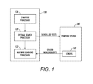
- FIG. 1 is a schematic diagram illustrating feedback from the sensors of the marking engines to the fault identification system (FIS) in an exemplary system herein;
- FIS fault identification system
- FIG. 2 is a schematic diagram illustrating a printing system controller, including a fault identification system (FIS) that interacts with a printing system to identify faults in an exemplary system herein;
- FIS fault identification system
- FIG. 3 is a flow chart illustrating a method of fault identification in a printing system that dynamically reduces a number of tests required to diagnose a fault in an exemplary method herein;
- FIG. 4 is a schematic diagram illustrating an exemplary system herein
- FIG. 5 is a schematic diagram illustrating an exemplary device herein.
- FIG. 6 is a schematic diagram illustrating an exemplary device herein.
- fault identification is useful to reconfigure a printing system, so as to operate in the presence of one or more faults, i.e., a fault tolerant system.
- This disclosure presents systems and methods for reliably identifying faults in a printing system that carry out as few tests as possible in order to identify the faults.
- a fault identification system (FIS) of the printing system may include: (1) a machine learning component that maps all sensor measurements in real time to probabilities of occurrences of faults; (2) a Dependency-matrix (D-matrix) component that provides a D-matrix; and (3) an optimal search component that repeatedly: implements a Rate of Return (ROR) that links the probabilities of occurrences of the faults to a priori probabilities of independent faults and a detection function of the ROR to elements of the D-matrix; determines a ROR value as one of: an incremental probability of a particular fault being detected by one more particular test; and the incremental probability of the particular fault divided by an incremental cost of conducting the one more particular test; provides a benefit defined as one of: a maximum ROR value, and a sum of maximum ROR values, over all faults, for any fault being detected by the one more particular test; and sends the one more particular test to the scheduler of the printing system controller.
- ROR Rate of Return
- the printing system then physically implement the one more particular test, so as to dynamically reduce a number of tests required to diagnose a fault in the printing system.
- the printing system repeats the prior steps of implementing a ROR, determining a ROR value, providing a benefit, sending the one more particular test to the scheduler, and physically implementing the one more particular test, until any of: a number of tests run, a predetermined accumulation of incremental costs, a predetermined benefit is reached, and a fault is diagnosed.
- FIG. 1 schematically illustrates the feedback from the sensors of the marking engines to the fault identification system (FIS) 120 in an exemplary example of systems and methods herein.
- Sensors 147 of the printing system 140 provide real time measurements to the FIS 120 .
- the machine learning component 123 maps all the real time sensor measurements into probabilities of occurrences of the faults.
- the D-matrix matrix component 126 provides a D-matrix corresponding to the components of the printing system 140 .
- the optimal search component 129 repeatedly implements a Rate of Return (ROR), determines a ROR value, provides a benefit, and sends one more test to the scheduler of the printing system 140 , until a stopping condition is reached and a fault is diagnosed.
- the printing system 140 then physically implements the one more test, received from the FIS 120 .
- ROR Rate of Return
- a real time measurement, S m may be obtained from sensor m, where m ⁇ ⁇ 1, . . . , M ⁇ .
- the operation of the printing system may be associated with a number of operation modes, o, including normal operation modes and faulty operation modes, where o ⁇ 1, . . . , L ⁇ .
- a machine learning component of the fault identification system may be trained to compute a priori probabilities, P, of fault occurrences o in the printing system and to classify the modes of operation by mapping all the available real time measurement data, S m , into a set of probabilities of the occurrence of all of the operation modes, such that P(o
- S 1 , . . . , S m ) for o ⁇ 1, . . . , L ⁇ may include any one of the well-known methods of logistic regression, linear discriminant analysis, and classification trees.
- An additional step may be included between the real time sensor measurements obtained from each of the plurality of sensors, m, and the classifying of the modes of operation that can result in better performance and/or speed of the classifying of the modes of operation.
- This additional step may include using Process Control Monitoring to map the real time sensor measurements, Sm, into a lower dimensional space.
- PCA Principal Component Analysis
- Sm Squared Prediction Error
- the fault identification system (FIS) of the printing system may further include a Dependency matrix (D-matrix) component, where the D-matrix is an N Q ⁇ N F matrix with Q rows associated with Q tests, F columns associated with F faults, and elements in the matrix capturing the relationship between tests, related to a query of a sensor measurement, and faults.
- D-matrix Dependency matrix
- the element represented by test i and fault j contains the probability distribution ⁇ (i
- the fault identification system (FIS) of the printing system may yet further include search-theoretic Rate of Return (ROR) maps that have relationships between the D-matrix and a method of classifying modes of operation to obtain P(o
- the optimal search for faults in a printing system may use two methods based on ROR: the payoff of detecting a fault divided by the cost of conducting the test, and the payoff of detecting a fault.
- the detection strategy may use the particular test where a single fault is most likely to be detected, or to use the test where any fault is most likely to be detected.
- N Q tests there are N Q tests, corresponding to queries of sensors to identify modes of normal operation and modes of faulty operation, and N F distinct faults that the FIS may consider. Due to sensor inaccuracies, a single test may not detect a fault; multiple tests of the same particular type may be needed to detect a fault.
- a Rate of Return (ROR) map may be implemented as follows.
- the FIS has access to a computed a priori probability, p(j), from the machine learning component that a particular fault occurs when j ⁇ F.
- p(j) a priori probability
- These probabilities are mutually independent and the faults are distinct when detected; that is, the FIS can identify which fault is detected.
- the sum ⁇ j ⁇ F p(j) links the probabilities P(o
- a measure of the amount of search effort dedicated to test i ⁇ Q of the N Q tests may be l k (i) ⁇ 0, 1, 2, . . . ⁇ , where l k (i) is the number of tests i performed by time index k.
- a j,i >0 be a parameter that is proportional to a sensor's determination of a fault, j, when test i is performed.
- the parameter a j,i may also simulate modes of faulty operation when, for example, tests are not performed and monitored by the same equipment and/or person.
- the probability that the FIS detects fault j when test i is performed once is ⁇ (j
- i, l k (i)) which denotes the conditional probability of detecting fault j when test i is performed by the time index k, given that fault j is detect by test i. If each test i has an independent probability function of finding fault j, then the detection function is: b ( j
- i,l k ( i )) 1 ⁇ (1 ⁇ ( j
- i, l k (i)) may be thought of as the probability that fault j ⁇ F is detected using test i ⁇ Q.
- a j,i >1 or a j,i ⁇ 1 may correspond to a more or less, respectively, effective sensor.
- Equation (1) models the common situation with sensor where the probability of detecting a fault increases as the number of tests increases.
- i) and a j,i mean that the sensor is better at detecting a fault using a particular test since fewer tests i are needed to detect a fault. Some tests may be more difficult to implement, while some faults are more difficult to detect.
- Each of these situations may be quantified with the ⁇ (j
- the payoff for searching for fault j may be defined as p(j)b(j
- the probability of failing to detect fault j using test i on the first attempt l k (i) and succeeding on the next possible attempt (l k (i)+1), given that fault j is detected by test i, may be given by ⁇ j (l k (i)+1).
- i, l k (i)+1) represents the detection function computed by time index k when the system performs the one more attempt of test i.
- the rate of return (ROR) of test i for fault j may be defined in order to determine a benefit, which the system obtains at time index k, when the one more test i is performed to detect fault j.
- a strategy may command the system to search for the fault with the maximum ROR map value.
- the strategy “use the one more test where any fault is most likely to be detected”, dynamically reduces the number of tests required to identify a fault in the system.
- Equation (3) the ROR values are computed by Equation (3), either Equation (4) or Equation (5) only requires the computation of the maximum element of N Q values.
- i, l k (i)) of the ROR maps and the D-matrix, represented by ⁇ (i, m 0
- j), j ⁇ F, i ⁇ Q, where m denotes the matrix elements of the D-matrix, may use Bayes rule to relate the ROR maps and the D-matrix by the following equation: ⁇ ( j
- i,m ) [ p ( j ) ⁇ ( i,m
- i ) ⁇ m ⁇ O [p ( j ) ⁇ ( i,m
- the system may compute the probability ⁇ (j
- an image input device 203 supplies the printing system 230 with one or more print jobs to be printed.
- the image input device 203 may be a built-in optical scanner, which can be used to scan a document such as book pages, a stack of printed pages, or the like, to create a digital image of the scanned document that is reproduces by printing operations performed by the printing system 230 .
- the print job may be electronically delivered to the printing system 230 by a wired or wireless connection to a digital network that interconnects, for example, personal computers, or other digital image devices.
- the incoming print jobs may be processed by a conventional digitizer 206 having raster image processing and print spooling capabilities. Image data 209 from the digitizer 206 is sent to a selected marking engine or engines for printing according to a schedule determined by the printing system controller 210 .
- an exemplary printing system 230 includes printing modules 240 , 250 , 260 , 270 that detects faults 249 , 259 , 269 , 279 from measurements by sensors 247 , 257 , 267 , 277 and a printing system controller 210 , in communication with the printing modules 240 , 250 , 260 , 270 .
- the printing modules of the printing system 230 include: one or more marking engines, 240 ; an optional final fuser, 250 ; a print media conveyor, 260 ; and an output destination, such as a finisher, 270 .
- the print media conveyor, 260 connects the printing modules 240 , 250 , and 270 .
- Providing at least two marking engines 240 provides for enhanced features of the printing system 230 , where one marking engine may be a monochrome engine, such as a black (K) marking engine, while another marking engine may be a multi-color, e.g., a process color (P) marking engine.
- Providing at least two marking engines 240 also allows reconfiguration of the printing system 230 , when, for example, a catastrophic fault is identified in one marking engine and the printing system 230 is reconfigured to use another marking engine to complete a print job.
- Each marking engine 240 includes various subsystems: an image path 241 including components of the marking engine associated with manipulation of the image prior to marking; a marking media path 243 including components of the marking engine associated with forming, transferring and optionally fusing images to print media; and a print media path 245 including components of the marking engine associated with media handling, such as the conveyor system 260 , including paper feeder, paper path, and associated drives.
- Each of the printing modules 240 , 250 , 260 , and 270 includes real time sensors 247 , 257 , 267 , 277 and corresponding fault detection 249 , 259 , 269 , 279 that that may provide preliminary analysis such as time-out checks, threshold checks, trend and rate analysis of output settings between similar units in the printing system 230 , checks of actuators and sensor signals for deviation from normal, both in magnitude and frequency. Additionally, fault detection components 249 , 259 , 269 , 279 may include checking fault counters for abnormally high values, or a higher than normal rate of change.
- the printing controller system 210 includes a number of components that serve to identify faults in the printing modules 240 , 250 , 260 , 270 , provide information on the faults to an external user interface 214 , and reconfigure the printing system 230 while permanent repairs or replacements, resulting from identified faults, are effected.
- the printing system controller includes: a fault identification system (FIS) 220 ; a scheduler 212 that communicates with the FIS 220 , a user interface 214 , a reconfiguration agent 216 , and a printing system 230 , and that determines the appropriate marking engine for a print job and the appropriate printing modules for effecting printing of a page; a user-interface 214 that allows users to input their preferences to the FIS 220 , the scheduler 212 , and the reconfiguration agent 216 ; a reconfiguration agent 216 that allows the printing modules 240 , 250 , 260 , 270 to be reconfigured, via the scheduler 212 , for a print job when a fault is identified.
- FIS fault identification system
- scheduler 212 that communicates with the FIS 220 , a user interface 214 , a reconfiguration agent 216 , and a printing system 230 , and that determines the appropriate marking engine for a print job and the appropriate printing modules for effecting printing of a page
- the fault identification system (FIS) 220 includes: a memory 218 , a machine learning component 226 ; a Dependency-matrix (D-matrix) component 223 , and an optimal search component 229 .
- the machine learning component 226 also communicates with the printing system 230 .
- the D-matrix component 223 and the machine learning component 226 provide inputs to the optimal search component 229 .
- the optimal search component 229 also communicates with the scheduler 212 .
- the Dependency matrix (D-matrix) component 223 operates upon a D-matrix, which is an N Q ⁇ N F matrix with Q rows associated with Q tests, F columns associated with F faults, as explained above.
- the elements of the matrix represent the probability distribution of a particular test, which is related to a sensor measurement(s), given the occurrence of a particular fault.
- the machine learning component 226 may iteratively map all real time sensor measurements obtained from sensors 247 , 257 , 267 , 277 , into probabilities of the occurrences of the faults.
- the methods of mapping the probabilities of the occurrences of the faults may include any one of the well-known methods of logistic regression, linear discriminant analysis, and classification trees.
- An additional step may be included between the real time measurements obtained from each of the plurality of sensors and the mapping of the probabilities of the occurrences of the faults by the machine learning component 226 , that results in better performance and/or speed.
- Process Control Monitoring PCM
- Principal Component Analysis or factory analysis may be used in this additional step to reduce the original number of real time measurements to low-dimensional components that facilitate training of the mapping of the probabilities of the occurrences of the faults and/or to increase the speed of the mapping of the probabilities of the occurrences of the faults.
- Hotelling's t-squared or the Squared Prediction Error may be computed, using the sensor data, and the computed values may be used as additional inputs to increase the accuracy of mapping of the probabilities of the occurrences of the faults.
- a strategy selected by a user may command the optimal search component 229 of the printing system controller 210 to search for the fault with the maximum Rate of Return (ROR) map value.
- the optimal search component 229 using Bayes rule may relate the probability distribution ⁇ (i, m
- Equation (3) the ROR values are computed by Equation (3), either Equation (4) or Equation (5) only requires the computation of the maximum element of N Q values.
- the optimal search component 229 may provide the maximum probability for one of “use the one more test where a single fault is most likely to be detected” and “use the one more test where any fault is most likely to be detected,” to send the one more test corresponding to the selected maximum probability to the scheduler 212 for implementation by the printing system 230 , so as to dynamically reduce a number of tests required to identify a fault in the printing system.
- FIG. 3 illustrates a flowchart 300 for a method for fault identification of a printing system.
- the method may include iteratively mapping, in a machine learning component of a printing system controller of a printing system, all real time sensor measurements from all sensors into probabilities of occurrences of faults, 310 .
- the method may also include constructing, by a D-matrix component of the printing system controller, a D-matrix, 320 .
- the method may further include implementing a Rate of Return (ROR), by an optimal search component of the printing system controller, that links the probabilities of occurrences of the faults to a priori probabilities of independent faults and a detection function of the ROR to elements of the D-matrix, 330 .
- ROR Rate of Return
- the method may yet further include determining an ROR value, by the optimal search component, defined as one of: an incremental probability of a particular fault being detected by one more particular test; and the incremental probability of the particular fault being detected by the one more particular test divided by an incremental cost of conducting the one more particular test, 340 .
- the method may yet further include providing a benefit, by the optimal search component, defined as one of: a maximum ROR value, and a sum of maximum ROR values, over all faults, for any fault being detected by the one more particular test, 350 .
- the method may yet further include sending, by the optimal search component, the one more particular test to the scheduler of the printing system controller, 360 .
- the method may include physically implementing, by the printing system, the one more particular test, so as to dynamically reduce a number of tests required to diagnose a fault in the printing system, 370 .
- the method may yet further include repeating, by the optimal search component, the prior steps of implementing a ROR, determining an ROR value, providing a benefit, sending the one more particular test to the scheduler, and by the printing system, physically implementing the one more particular test, until any of: a number of tests run, a predetermined accumulation of incremental costs, a predetermined benefit is reached, and a fault is diagnosed, 380 .
- HVAC Heating, Ventilating, and Air Conditioning
- exemplary systems and methods herein include various computerized devices 400 , 404 located at various different physical locations 406 .
- the computerized devices 400 , 404 can include print servers, printing devices, personal computers, etc., and are in communication (operatively connected to one another) by way of a local or wide area (wired or wireless) network 402 .
- FIG. 5 illustrates a computerized device 500 , which can be used with systems and methods herein and can comprise, for example, a print server, a personal computer, a portable computing device, etc.
- the computerized device 500 includes a controller/tangible processor 516 and a communications port (input/output) 514 operatively connected to the tangible processor 516 and to the computerized network external to the computerized device 500 .
- the computerized device 500 can include at least one accessory functional component, such as a graphical user interface (GUI) assembly 512 .
- GUI graphical user interface
- the input/output device 514 is used for communications to and from the computerized device 500 and comprises a wired device or wireless device (of any form, whether currently known or developed in the future).
- the tangible processor 516 controls the various actions of the computerized device.
- a non-transitory, tangible, computer storage medium device 510 (which can be optical, magnetic, capacitor based, etc., and is different from a transitory signal) is readable by the tangible processor 516 and stores instructions that the tangible processor 516 executes to allow the computerized device to perform its various functions, such as those described herein.
- a body housing has one or more functional components that operate on power supplied from an alternating current (AC) source 520 by the power supply 518 .
- the power supply 518 can comprise a common power conversion unit, power storage element (e.g., a battery, etc), etc.
- the hardware described herein plays a significant part in permitting the foregoing method to be performed, rather than function solely as a mechanism for permitting a solution to be achieved more quickly, (i.e., through the utilization of a computer for performing calculations).
- the processes described herein cannot be performed by a human alone (or one operating with a pen and a pad of paper) and instead such processes can only be performed by a machine (especially when the volume of data being processed, and the speed at which such data needs to be evaluated is considered). For example, if one were to manually attempt to perform the classification processing performed by the machine learning component discussed above, the manual process would be sufficiently inaccurate and take an excessive amount of time so as to render the manual fault identification results useless.
- processes such as receiving electronic data streams from printing components and sensors, updating automated processes, using the processes to automatically determine which fault test to perform, etc., requires the utilization of different specialized machines, and humans performing such processing would not produce useful results because of the time lag, inconsistency, and inaccuracy humans would introduce into the results.
- the data transmitted between the sensors, printing components, processor(s) etc. is integral with the process performed by the methods herein, and is not mere post-solution activity, because the testing processes of the methods herein rely upon the electronic transmissions from sensors and printing components, and cannot be performed without such electronic transmissions.
- these various machines are integral with the methods herein because the methods cannot be performed without the machines (and cannot be performed by humans alone).
- the methods herein solve many highly complex technological problems. For example, as mentioned above, conventional fault identification systems perform many unnecessary tests. Methods herein solve this technological problem by reliably identifying faults in a printing system that carry out as few tests as possible in order to identify the faults. This reduces the amount of electronic storage that a provider must maintain, and also reduces the down time of the equipment, saves power and other resources by not performing unnecessary tests, etc. By granting such benefits to providers, the methods herein reduce the amount and complexity of hardware and software needed to be purchased, installed, and maintained by providers, thereby solving a substantial technological problem that providers experience today.
- FIG. 6 illustrates many components of printer structures 604 herein that can comprise, for example, a printer, copier, multi-function machine, multi-function device (MFD), etc.
- the printing device 604 includes a controller/tangible processor 624 and a communications port (input/output) 614 operatively connected to the tangible processor 624 and to a computerized network external to the printing device 604 .
- the printing device 604 can include at least one accessory functional component, such as a graphical user interface (GUI) assembly 612 .
- GUI graphical user interface
- the input/output device 614 is used for communications to and from the printing device 604 and comprises a wired device or wireless device (of any form, whether currently known or developed in the future).
- the tangible processor 624 controls the various actions of the printing device 604 .
- a non-transitory, tangible, computer storage medium device 610 (which can be optical, magnetic, capacitor based, etc., and is different from a transitory signal) is readable by the tangible processor 624 and stores instructions that the tangible processor 624 executes to allow the computerized device to perform its various functions, such as those described herein.
- a body housing has one or more functional components that operate on power supplied from an alternating current (AC) source 620 by the power supply 618 .
- the power supply 618 can comprise a common power conversion unit, power storage element (e.g., a battery, etc), etc.
- the printing device 604 includes at least one marking device (printing engine(s)) 640 that use marking material, and are operatively connected to a specialized image processor 624 (that is different than a general purpose computer because it is specialized for processing image data), a media path 636 positioned to supply continuous media or sheets of media from a sheet supply 630 to the marking device(s) 640 , etc.
- a specialized image processor 624 that is different than a general purpose computer because it is specialized for processing image data
- the sheets of media can optionally pass to a finisher 634 which can fold, staple, sort, etc., the various printed sheets.
- the printing device 604 can include at least one accessory functional component (such as a scanner/document handler 632 (automatic document feeder (ADF)), etc.) that also operate on the power supplied from the external power source 620 (through the power supply 618 ).
- ADF automatic document feeder
- the one or more printing engines 640 are intended to illustrate any marking device that applies marking material (toner, inks, plastics, organic material, etc.) to continuous media, sheets of media, fixed platforms, etc., in two- or three-dimensional printing processes, whether currently known or developed in the future.
- the printing engines 640 can include, for example, devices that use electrostatic toner printers, inkjet printheads, contact printheads, three-dimensional printers, etc.
- the one or more printing engines 640 can include, for example, devices that use a photoreceptor belt or an intermediate transfer belt or devices that print directly to print media (e.g., inkjet printers, ribbon-based contact printers, etc.).
- Computerized devices that include chip-based central processing units (CPU's), input/output devices (including graphic user interfaces (GUI), memories, comparators, tangible processors, etc.) are well-known and readily available devices produced by manufacturers such as Dell Computers, Round Rock Tex., USA and Apple Computer Co., Cupertino Calif., USA.
- Such computerized devices commonly include input/output devices, power supplies, tangible processors, electronic storage memories, wiring, etc., the details of which are omitted herefrom to allow the reader to focus on the salient aspects of the systems and methods described herein.
- printers, copiers, scanners and other similar peripheral equipment are available from Xerox Corporation, Norwalk, Conn., USA and the details of such devices are not discussed herein for purposes of brevity and reader focus.
- printer or printing device encompasses any apparatus, such as a digital copier, bookmaking machine, facsimile machine, multi-function machine, etc., which performs a print outputting function for any purpose.
- the details of printers, printing engines, etc. are well-known and are not described in detail herein to keep this disclosure focused on the salient features presented.
- the systems and methods herein can encompass systems and methods that print in color, monochrome, or handle color or monochrome image data. All foregoing systems and methods are specifically applicable to electrostatographic and/or xerographic machines and/or processes.
- the terms automated or automatically mean that once a process is started (by a machine or a user), one or more machines perform the process without further input from any user.
- the same identification numeral identifies the same or similar item.
Landscapes
- Engineering & Computer Science (AREA)
- Theoretical Computer Science (AREA)
- Physics & Mathematics (AREA)
- General Engineering & Computer Science (AREA)
- General Physics & Mathematics (AREA)
- Evolutionary Computation (AREA)
- Artificial Intelligence (AREA)
- Mathematical Optimization (AREA)
- Mathematical Physics (AREA)
- Mathematical Analysis (AREA)
- Computational Mathematics (AREA)
- Pure & Applied Mathematics (AREA)
- Computing Systems (AREA)
- Algebra (AREA)
- Data Mining & Analysis (AREA)
- Software Systems (AREA)
- Probability & Statistics with Applications (AREA)
- Computer Hardware Design (AREA)
- Quality & Reliability (AREA)
- Human Computer Interaction (AREA)
- Control Or Security For Electrophotography (AREA)
Abstract
Description
| TABLE 1 | ||||
| F1 | F2 | F3 | F4 | |
| T1 | 0 | 0 | 0 | 0 |
| T2 | 0 | 1 | 1 | 1 |
| T3 | 0 | 0 | 1 | 1 |
| |
1 | 1 | 0 | 0 |
b(j|i,l k(i))=1−(1−π(j|i))(a
βj(l k(i)+1)=b(j|i,l k(i)+1)−b(j|i,l k(i)), (2)
ρj(l k(i)+1)=[p(j)βj(l k(i)+1)]/[γj(l k(i)+1)], (3)
i*(k)=arg maxjεF,iεQ{ρj(l k(i)+1)}, (4)
i*(k)=arg maxiεQ{ΣjεFρj(l k(i)+1)}. (5)
π(j|i,m)=[p(j)π(i,m|j)]/[ΣjεF p(j)π(i,m|j)]
π(j|i)=ΣmεO [p(j)π(i,m|j)]/[ΣjεF p(j)π(i,m|j)].
i*(k)=arg maxjεF,iεQ{ρj(l k(i)+1)}.
i*(k)=arg maxiεQ{ΣjεFρj(l k(i)+1)}.
Claims (20)
Priority Applications (1)
| Application Number | Priority Date | Filing Date | Title |
|---|---|---|---|
| US15/177,406 US9696947B1 (en) | 2016-06-09 | 2016-06-09 | Fault identification for a printing system |
Applications Claiming Priority (1)
| Application Number | Priority Date | Filing Date | Title |
|---|---|---|---|
| US15/177,406 US9696947B1 (en) | 2016-06-09 | 2016-06-09 | Fault identification for a printing system |
Publications (1)
| Publication Number | Publication Date |
|---|---|
| US9696947B1 true US9696947B1 (en) | 2017-07-04 |
Family
ID=59191806
Family Applications (1)
| Application Number | Title | Priority Date | Filing Date |
|---|---|---|---|
| US15/177,406 Active US9696947B1 (en) | 2016-06-09 | 2016-06-09 | Fault identification for a printing system |
Country Status (1)
| Country | Link |
|---|---|
| US (1) | US9696947B1 (en) |
Cited By (7)
| Publication number | Priority date | Publication date | Assignee | Title |
|---|---|---|---|---|
| CN107656711A (en) * | 2017-08-31 | 2018-02-02 | 深圳市盛路物联通讯技术有限公司 | Fault alarming method and relevant device |
| CN108427388A (en) * | 2018-04-11 | 2018-08-21 | 广东工业大学 | A kind of R2R manufacture systems fault coverage determines method and device |
| US10337753B2 (en) * | 2016-12-23 | 2019-07-02 | Abb Ag | Adaptive modeling method and system for MPC-based building energy control |
| CN110060374A (en) * | 2019-04-19 | 2019-07-26 | 中国航空无线电电子研究所 | A kind of aircraft fuel system method for detecting abnormality and device |
| US20190318837A1 (en) * | 2016-12-22 | 2019-10-17 | Electricite De France | Method For Characterising One Or More Faults In A System |
| US10901669B2 (en) | 2017-11-08 | 2021-01-26 | Ricoh Company, Ltd. | Mechanism to predict print performance using print metadata |
| US11861309B2 (en) | 2019-01-30 | 2024-01-02 | Hewlett-Packard Development Company, L.P. | Processing service notes |
Citations (3)
| Publication number | Priority date | Publication date | Assignee | Title |
|---|---|---|---|---|
| US6442542B1 (en) * | 1999-10-08 | 2002-08-27 | General Electric Company | Diagnostic system with learning capabilities |
| US20100306249A1 (en) * | 2009-05-27 | 2010-12-02 | James Hill | Social network systems and methods |
| US20130304683A1 (en) * | 2010-01-19 | 2013-11-14 | James Ting-Ho Lo | Artificial Neural Networks based on a Low-Order Model of Biological Neural Networks |
-
2016
- 2016-06-09 US US15/177,406 patent/US9696947B1/en active Active
Patent Citations (3)
| Publication number | Priority date | Publication date | Assignee | Title |
|---|---|---|---|---|
| US6442542B1 (en) * | 1999-10-08 | 2002-08-27 | General Electric Company | Diagnostic system with learning capabilities |
| US20100306249A1 (en) * | 2009-05-27 | 2010-12-02 | James Hill | Social network systems and methods |
| US20130304683A1 (en) * | 2010-01-19 | 2013-11-14 | James Ting-Ho Lo | Artificial Neural Networks based on a Low-Order Model of Biological Neural Networks |
Non-Patent Citations (5)
| Title |
|---|
| Alina Beygelzimer et al., "Test-BAsed Diagnosis: Tree and Matrix Representations", IEEE 2005, pp. 1-14. |
| Alvaro Gil et al., "Stable Cooperative Surveillance With Information Flow Constraints", IEEE Transactions on Control Systems Technology, vol. 16, No. 5, Sep. 2008, pp. 856-868. |
| David A. Castanon, Optimal Search Strategies in Dynamic Flyposthesis Testing, IEEE Transactions on Systems, Main and Cybernetics vol. 25, No. 7, Jul. 1995, pp. 1130-1138. |
| J. W. Sheppard et al., "A Formal Analysis of Fault Diagnosis with D-matrices", Journal of Electronic Testing: Theory and Applications, 2007, Springer Science + Business Media, LLC, pp. 1-14. |
| Michael Baum et al., "A Search-Theoretic Approach to Cooperative Control for Uninhabited Air Vehicles", AIAA Guidance, Navigation, and Control Conference and Exhibit Aug. 5-8, 2002, Monterey, California, pp. 1-8. |
Cited By (10)
| Publication number | Priority date | Publication date | Assignee | Title |
|---|---|---|---|---|
| US20190318837A1 (en) * | 2016-12-22 | 2019-10-17 | Electricite De France | Method For Characterising One Or More Faults In A System |
| US10337753B2 (en) * | 2016-12-23 | 2019-07-02 | Abb Ag | Adaptive modeling method and system for MPC-based building energy control |
| CN107656711A (en) * | 2017-08-31 | 2018-02-02 | 深圳市盛路物联通讯技术有限公司 | Fault alarming method and relevant device |
| US10901669B2 (en) | 2017-11-08 | 2021-01-26 | Ricoh Company, Ltd. | Mechanism to predict print performance using print metadata |
| US11630623B2 (en) | 2017-11-08 | 2023-04-18 | Ricoh Company, Ltd. | Mechanism to predict print performance using print metadata |
| CN108427388A (en) * | 2018-04-11 | 2018-08-21 | 广东工业大学 | A kind of R2R manufacture systems fault coverage determines method and device |
| CN108427388B (en) * | 2018-04-11 | 2020-10-23 | 广东工业大学 | R2R manufacturing system fault range determining method and device |
| US11861309B2 (en) | 2019-01-30 | 2024-01-02 | Hewlett-Packard Development Company, L.P. | Processing service notes |
| CN110060374A (en) * | 2019-04-19 | 2019-07-26 | 中国航空无线电电子研究所 | A kind of aircraft fuel system method for detecting abnormality and device |
| CN110060374B (en) * | 2019-04-19 | 2021-06-01 | 中国航空无线电电子研究所 | Method and device for detecting abnormality of aircraft fuel system |
Similar Documents
| Publication | Publication Date | Title |
|---|---|---|
| US9696947B1 (en) | Fault identification for a printing system | |
| US8607102B2 (en) | Fault management for a printing system | |
| US8693021B2 (en) | Preemptive redirection in printing systems | |
| US8249830B2 (en) | Method and system for automatically diagnosing faults in rendering devices | |
| US8132049B2 (en) | Failure diagnosis method, failure diagnosis apparatus, conveyance device, image forming apparatus, program, and storage medium | |
| US5490089A (en) | Interactive user support system and method using sensors and machine knowledge | |
| US8902450B2 (en) | Methods and systems for soft failure detection for networked printers | |
| US20160044195A1 (en) | Imaging Device and Method for Sensing Media Type | |
| CN110703723B (en) | System, method, and non-transitory computer-readable storage medium | |
| JP2001175328A (en) | System and method for hybrid diagnostic system for executing real time diagnosis of electronic system | |
| US8643865B2 (en) | Maintenance system and maintenance method for image processing apparatus | |
| JP5598293B2 (en) | Image forming system, prediction reference setting device, prediction device, image forming device, and program | |
| US8725008B2 (en) | Using images to diagnose defects in an image forming apparatus | |
| US20140013156A1 (en) | Method and system for managing image forming apparatus through network | |
| US8913273B2 (en) | Workflow to allow continued printing in presence of severe printer error | |
| US8594518B2 (en) | Diagnostic method for determining imager contribution to printing defects | |
| JP6384746B2 (en) | Image inspection apparatus and image inspection method | |
| US10628092B1 (en) | Automated system and method for prediction of device settings for stocks | |
| JP4784225B2 (en) | Failure diagnosis apparatus, image forming apparatus, and failure diagnosis method | |
| US8437034B2 (en) | Dynamically adapted reprographic system to current operating environment based on probabilistic network | |
| JP7302435B2 (en) | Image processing system and server | |
| JP2019159069A (en) | Fault diagnosis system | |
| US10599086B1 (en) | Automated stock evaluation system and method | |
| US20040252334A1 (en) | Communication control device and method for image forming system | |
| US11172075B2 (en) | Device management system, apparatus, and device involving request to change to a higher failure risk condition that changes the target device monitoring condition |
Legal Events
| Date | Code | Title | Description |
|---|---|---|---|
| AS | Assignment |
Owner name: XEROX CORPORATION, CONNECTICUT Free format text: ASSIGNMENT OF ASSIGNORS INTEREST;ASSIGNOR:GIL, ALVARO;REEL/FRAME:038926/0909 Effective date: 20160531 |
|
| FEPP | Fee payment procedure |
Free format text: PAYOR NUMBER ASSIGNED (ORIGINAL EVENT CODE: ASPN); ENTITY STATUS OF PATENT OWNER: LARGE ENTITY |
|
| STCF | Information on status: patent grant |
Free format text: PATENTED CASE |
|
| MAFP | Maintenance fee payment |
Free format text: PAYMENT OF MAINTENANCE FEE, 4TH YEAR, LARGE ENTITY (ORIGINAL EVENT CODE: M1551); ENTITY STATUS OF PATENT OWNER: LARGE ENTITY Year of fee payment: 4 |
|
| AS | Assignment |
Owner name: CITIBANK, N.A., AS AGENT, DELAWARE Free format text: SECURITY INTEREST;ASSIGNOR:XEROX CORPORATION;REEL/FRAME:062740/0214 Effective date: 20221107 |
|
| AS | Assignment |
Owner name: XEROX CORPORATION, CONNECTICUT Free format text: RELEASE OF SECURITY INTEREST IN PATENTS AT R/F 062740/0214;ASSIGNOR:CITIBANK, N.A., AS AGENT;REEL/FRAME:063694/0122 Effective date: 20230517 |
|
| AS | Assignment |
Owner name: CITIBANK, N.A., AS COLLATERAL AGENT, NEW YORK Free format text: SECURITY INTEREST;ASSIGNOR:XEROX CORPORATION;REEL/FRAME:064760/0389 Effective date: 20230621 |
|
| AS | Assignment |
Owner name: JEFFERIES FINANCE LLC, AS COLLATERAL AGENT, NEW YORK Free format text: SECURITY INTEREST;ASSIGNOR:XEROX CORPORATION;REEL/FRAME:065628/0019 Effective date: 20231117 |
|
| AS | Assignment |
Owner name: XEROX CORPORATION, CONNECTICUT Free format text: TERMINATION AND RELEASE OF SECURITY INTEREST IN PATENTS RECORDED AT RF 064760/0389;ASSIGNOR:CITIBANK, N.A., AS COLLATERAL AGENT;REEL/FRAME:068261/0001 Effective date: 20240206 Owner name: CITIBANK, N.A., AS COLLATERAL AGENT, NEW YORK Free format text: SECURITY INTEREST;ASSIGNOR:XEROX CORPORATION;REEL/FRAME:066741/0001 Effective date: 20240206 |