US9692612B2 - Distributed CCAP cable modem termination system - Google Patents
Distributed CCAP cable modem termination system Download PDFInfo
- Publication number
- US9692612B2 US9692612B2 US15/083,215 US201615083215A US9692612B2 US 9692612 B2 US9692612 B2 US 9692612B2 US 201615083215 A US201615083215 A US 201615083215A US 9692612 B2 US9692612 B2 US 9692612B2
- Authority
- US
- United States
- Prior art keywords
- data
- cable
- qam
- upstream
- optical fiber
- Prior art date
- Legal status (The legal status is an assumption and is not a legal conclusion. Google has not performed a legal analysis and makes no representation as to the accuracy of the status listed.)
- Active
Links
- 101710184216 Cardioactive peptide Proteins 0.000 title abstract 2
- 239000000835 fiber Substances 0.000 claims abstract description 223
- 239000013307 optical fiber Substances 0.000 claims abstract description 137
- 230000003287 optical effect Effects 0.000 claims abstract description 64
- 230000005540 biological transmission Effects 0.000 claims abstract description 12
- 238000011144 upstream manufacturing Methods 0.000 claims description 87
- 238000000034 method Methods 0.000 claims description 57
- 238000004891 communication Methods 0.000 claims description 31
- 230000006870 function Effects 0.000 claims description 23
- 238000006243 chemical reaction Methods 0.000 claims description 18
- 230000002708 enhancing effect Effects 0.000 claims description 2
- 230000001360 synchronised effect Effects 0.000 claims description 2
- 238000007726 management method Methods 0.000 description 18
- 238000001228 spectrum Methods 0.000 description 16
- 102100033973 Anaphase-promoting complex subunit 10 Human genes 0.000 description 12
- OAUWKHSGCCPXOD-UHFFFAOYSA-N DOC1 Natural products C1=CC(O)=C2C(CC(=O)NCCCCCNCCCNCCCNCCCN)=CNC2=C1 OAUWKHSGCCPXOD-UHFFFAOYSA-N 0.000 description 12
- 101000779315 Homo sapiens Anaphase-promoting complex subunit 10 Proteins 0.000 description 12
- 101000737813 Homo sapiens Cyclin-dependent kinase 2-associated protein 1 Proteins 0.000 description 12
- 230000008569 process Effects 0.000 description 11
- 238000013461 design Methods 0.000 description 7
- 238000009826 distribution Methods 0.000 description 7
- 230000001965 increasing effect Effects 0.000 description 6
- 102100035353 Cyclin-dependent kinase 2-associated protein 1 Human genes 0.000 description 5
- 230000008901 benefit Effects 0.000 description 5
- 230000008859 change Effects 0.000 description 5
- 238000002347 injection Methods 0.000 description 4
- 239000007924 injection Substances 0.000 description 4
- 239000000203 mixture Substances 0.000 description 4
- 230000000153 supplemental effect Effects 0.000 description 4
- 102100028188 Cystatin-F Human genes 0.000 description 3
- 101710169749 Cystatin-F Proteins 0.000 description 3
- 102100028572 Disabled homolog 2 Human genes 0.000 description 3
- 101000866272 Homo sapiens Double C2-like domain-containing protein alpha Proteins 0.000 description 3
- 239000003795 chemical substances by application Substances 0.000 description 3
- 238000010586 diagram Methods 0.000 description 2
- 238000005516 engineering process Methods 0.000 description 2
- 230000006872 improvement Effects 0.000 description 2
- 239000002609 medium Substances 0.000 description 2
- 229920006395 saturated elastomer Polymers 0.000 description 2
- 239000000243 solution Substances 0.000 description 2
- 239000006163 transport media Substances 0.000 description 2
- 101100264195 Caenorhabditis elegans app-1 gene Proteins 0.000 description 1
- 230000004075 alteration Effects 0.000 description 1
- 238000013459 approach Methods 0.000 description 1
- 238000013475 authorization Methods 0.000 description 1
- 238000005520 cutting process Methods 0.000 description 1
- 238000011143 downstream manufacturing Methods 0.000 description 1
- 230000009977 dual effect Effects 0.000 description 1
- 230000000694 effects Effects 0.000 description 1
- 238000001914 filtration Methods 0.000 description 1
- 238000010348 incorporation Methods 0.000 description 1
- 238000009434 installation Methods 0.000 description 1
- 238000012423 maintenance Methods 0.000 description 1
- 238000004519 manufacturing process Methods 0.000 description 1
- 230000000873 masking effect Effects 0.000 description 1
- 230000007246 mechanism Effects 0.000 description 1
- 230000005055 memory storage Effects 0.000 description 1
- 230000004048 modification Effects 0.000 description 1
- 238000012986 modification Methods 0.000 description 1
- 230000006855 networking Effects 0.000 description 1
- 238000005192 partition Methods 0.000 description 1
- 230000037361 pathway Effects 0.000 description 1
- 230000000704 physical effect Effects 0.000 description 1
- 238000012545 processing Methods 0.000 description 1
- 230000009467 reduction Effects 0.000 description 1
- 230000004044 response Effects 0.000 description 1
- 230000000717 retained effect Effects 0.000 description 1
- 238000005096 rolling process Methods 0.000 description 1
- 239000004065 semiconductor Substances 0.000 description 1
- 238000007493 shaping process Methods 0.000 description 1
- 230000008054 signal transmission Effects 0.000 description 1
- 238000000638 solvent extraction Methods 0.000 description 1
- 239000013589 supplement Substances 0.000 description 1
- 238000012546 transfer Methods 0.000 description 1
Images


Classifications
-
- H—ELECTRICITY
- H04—ELECTRIC COMMUNICATION TECHNIQUE
- H04L—TRANSMISSION OF DIGITAL INFORMATION, e.g. TELEGRAPHIC COMMUNICATION
- H04L12/00—Data switching networks
- H04L12/28—Data switching networks characterised by path configuration, e.g. LAN [Local Area Networks] or WAN [Wide Area Networks]
- H04L12/2801—Broadband local area networks
-
- H—ELECTRICITY
- H04—ELECTRIC COMMUNICATION TECHNIQUE
- H04B—TRANSMISSION
- H04B10/00—Transmission systems employing electromagnetic waves other than radio-waves, e.g. infrared, visible or ultraviolet light, or employing corpuscular radiation, e.g. quantum communication
- H04B10/25—Arrangements specific to fibre transmission
- H04B10/2575—Radio-over-fibre, e.g. radio frequency signal modulated onto an optical carrier
- H04B10/25751—Optical arrangements for CATV or video distribution
-
- H—ELECTRICITY
- H04—ELECTRIC COMMUNICATION TECHNIQUE
- H04H—BROADCAST COMMUNICATION
- H04H20/00—Arrangements for broadcast or for distribution combined with broadcast
- H04H20/10—Arrangements for replacing or switching information during the broadcast or the distribution
-
- H—ELECTRICITY
- H04—ELECTRIC COMMUNICATION TECHNIQUE
- H04H—BROADCAST COMMUNICATION
- H04H20/00—Arrangements for broadcast or for distribution combined with broadcast
- H04H20/65—Arrangements characterised by transmission systems for broadcast
- H04H20/69—Optical systems
-
- H—ELECTRICITY
- H04—ELECTRIC COMMUNICATION TECHNIQUE
- H04H—BROADCAST COMMUNICATION
- H04H20/00—Arrangements for broadcast or for distribution combined with broadcast
- H04H20/65—Arrangements characterised by transmission systems for broadcast
- H04H20/76—Wired systems
- H04H20/77—Wired systems using carrier waves
- H04H20/78—CATV [Community Antenna Television] systems
-
- H—ELECTRICITY
- H04—ELECTRIC COMMUNICATION TECHNIQUE
- H04N—PICTORIAL COMMUNICATION, e.g. TELEVISION
- H04N21/00—Selective content distribution, e.g. interactive television or video on demand [VOD]
- H04N21/20—Servers specifically adapted for the distribution of content, e.g. VOD servers; Operations thereof
- H04N21/21—Server components or server architectures
- H04N21/222—Secondary servers, e.g. proxy server, cable television Head-end
- H04N21/2221—Secondary servers, e.g. proxy server, cable television Head-end being a cable television head-end
-
- H—ELECTRICITY
- H04—ELECTRIC COMMUNICATION TECHNIQUE
- H04N—PICTORIAL COMMUNICATION, e.g. TELEVISION
- H04N21/00—Selective content distribution, e.g. interactive television or video on demand [VOD]
- H04N21/20—Servers specifically adapted for the distribution of content, e.g. VOD servers; Operations thereof
- H04N21/23—Processing of content or additional data; Elementary server operations; Server middleware
- H04N21/238—Interfacing the downstream path of the transmission network, e.g. adapting the transmission rate of a video stream to network bandwidth; Processing of multiplex streams
- H04N21/2383—Channel coding or modulation of digital bit-stream, e.g. QPSK modulation
-
- H—ELECTRICITY
- H04—ELECTRIC COMMUNICATION TECHNIQUE
- H04N—PICTORIAL COMMUNICATION, e.g. TELEVISION
- H04N21/00—Selective content distribution, e.g. interactive television or video on demand [VOD]
- H04N21/20—Servers specifically adapted for the distribution of content, e.g. VOD servers; Operations thereof
- H04N21/23—Processing of content or additional data; Elementary server operations; Server middleware
- H04N21/239—Interfacing the upstream path of the transmission network, e.g. prioritizing client content requests
- H04N21/2393—Interfacing the upstream path of the transmission network, e.g. prioritizing client content requests involving handling client requests
- H04N21/2396—Interfacing the upstream path of the transmission network, e.g. prioritizing client content requests involving handling client requests characterized by admission policies
-
- H—ELECTRICITY
- H04—ELECTRIC COMMUNICATION TECHNIQUE
- H04N—PICTORIAL COMMUNICATION, e.g. TELEVISION
- H04N21/00—Selective content distribution, e.g. interactive television or video on demand [VOD]
- H04N21/60—Network structure or processes for video distribution between server and client or between remote clients; Control signalling between clients, server and network components; Transmission of management data between server and client, e.g. sending from server to client commands for recording incoming content stream; Communication details between server and client
- H04N21/61—Network physical structure; Signal processing
- H04N21/6106—Network physical structure; Signal processing specially adapted to the downstream path of the transmission network
- H04N21/6118—Network physical structure; Signal processing specially adapted to the downstream path of the transmission network involving cable transmission, e.g. using a cable modem
-
- H—ELECTRICITY
- H04—ELECTRIC COMMUNICATION TECHNIQUE
- H04N—PICTORIAL COMMUNICATION, e.g. TELEVISION
- H04N21/00—Selective content distribution, e.g. interactive television or video on demand [VOD]
- H04N21/60—Network structure or processes for video distribution between server and client or between remote clients; Control signalling between clients, server and network components; Transmission of management data between server and client, e.g. sending from server to client commands for recording incoming content stream; Communication details between server and client
- H04N21/61—Network physical structure; Signal processing
- H04N21/615—Signal processing at physical level
-
- H—ELECTRICITY
- H04—ELECTRIC COMMUNICATION TECHNIQUE
- H04N—PICTORIAL COMMUNICATION, e.g. TELEVISION
- H04N21/00—Selective content distribution, e.g. interactive television or video on demand [VOD]
- H04N21/60—Network structure or processes for video distribution between server and client or between remote clients; Control signalling between clients, server and network components; Transmission of management data between server and client, e.g. sending from server to client commands for recording incoming content stream; Communication details between server and client
- H04N21/61—Network physical structure; Signal processing
- H04N21/6156—Network physical structure; Signal processing specially adapted to the upstream path of the transmission network
- H04N21/6168—Network physical structure; Signal processing specially adapted to the upstream path of the transmission network involving cable transmission, e.g. using a cable modem
-
- H—ELECTRICITY
- H04—ELECTRIC COMMUNICATION TECHNIQUE
- H04N—PICTORIAL COMMUNICATION, e.g. TELEVISION
- H04N21/00—Selective content distribution, e.g. interactive television or video on demand [VOD]
- H04N21/60—Network structure or processes for video distribution between server and client or between remote clients; Control signalling between clients, server and network components; Transmission of management data between server and client, e.g. sending from server to client commands for recording incoming content stream; Communication details between server and client
- H04N21/63—Control signaling related to video distribution between client, server and network components; Network processes for video distribution between server and clients or between remote clients, e.g. transmitting basic layer and enhancement layers over different transmission paths, setting up a peer-to-peer communication via Internet between remote STB's; Communication protocols; Addressing
- H04N21/64—Addressing
- H04N21/6402—Address allocation for clients
-
- H—ELECTRICITY
- H04—ELECTRIC COMMUNICATION TECHNIQUE
- H04N—PICTORIAL COMMUNICATION, e.g. TELEVISION
- H04N21/00—Selective content distribution, e.g. interactive television or video on demand [VOD]
- H04N21/60—Network structure or processes for video distribution between server and client or between remote clients; Control signalling between clients, server and network components; Transmission of management data between server and client, e.g. sending from server to client commands for recording incoming content stream; Communication details between server and client
- H04N21/63—Control signaling related to video distribution between client, server and network components; Network processes for video distribution between server and clients or between remote clients, e.g. transmitting basic layer and enhancement layers over different transmission paths, setting up a peer-to-peer communication via Internet between remote STB's; Communication protocols; Addressing
- H04N21/643—Communication protocols
- H04N21/64322—IP
-
- H—ELECTRICITY
- H04—ELECTRIC COMMUNICATION TECHNIQUE
- H04N—PICTORIAL COMMUNICATION, e.g. TELEVISION
- H04N7/00—Television systems
- H04N7/10—Adaptations for transmission by electrical cable
-
- H—ELECTRICITY
- H04—ELECTRIC COMMUNICATION TECHNIQUE
- H04N—PICTORIAL COMMUNICATION, e.g. TELEVISION
- H04N7/00—Television systems
- H04N7/22—Adaptations for optical transmission
Definitions
- U.S. patent application Ser. No. 14/461,114 is also a continuation in part of U.S. patent application Ser. No. 14/328,494, “HYBRID ALL DIGITAL FIBER TO CATV CABLE SYSTEM AND METHOD”, filed Jul. 10, 2014; application Ser. No. 14/328,494 was a continuation of application Ser. No. 13/674,936, “HYBRID ALL DIGITAL FIBER TO CATV CABLE SYSTEM AND METHOD”, filed Nov. 12, 2012, now U.S. Pat. No. 8,782,729; U.S. patent application Ser. No. 13/674,936 was also a continuation in part of U.S. patent application Ser. No. 12/692,582, filed Jan.
- U.S. patent application Ser. No. 14/461,114 is also a continuation in part of U.S. patent application Ser. No. 13/756,302, filed Jan. 31, 2013, now U.S. Pat. No. 8,910,230; U.S. patent application Ser. No. 14/461,114 is also a continuation in part of U.S. patent application Ser. No. 14/098,656, “VIRTUAL CONVERGED CABLE ACCESS PLATFORMS FOR HFC CABLE NETWORKS”, filed Dec. 6, 2013, now U.S. Pat. No. 8,938,769; U.S. patent application Ser. No.
- 14/098,656 was a continuation of PCT/US13/69760, “VIRTUAL CONVERGED CABLE ACCESS PLATFORMS FOR HFC CABLE NETWORKS” filed Nov. 12, 2013; U.S. patent application Ser. No. 14/098,656 also claims the priority benefit of U.S. provisional application 61/870,226, “VIRTUAL HFC CONVERGED CABLE ACCESS PLATFORM”, filed Aug. 26, 2013, the contents of all of these applications are incorporated herein by reference.
- the invention is in the general field of Cable Television and Hybrid Fiber Cable systems, particularly with regard to providing extended features and Internet access.
- Cable television originally introduced in the late 1940's as a way to transmit television signals by coaxial cables to houses in areas of poor reception, has over the years been modified and extended to enable the cable medium to transport a growing number of different types of digital data, including both digital television and broadband Internet data.
- DOCSIS Data Over Cable Service Interface Specification
- analog television in the US transmitted television channels as a series of roughly 6 MHz bandwidth radiofrequency waveforms at frequencies ranging from about 54 MHz (originally used for VHF Channel 2) up to about 885 MHz for now no-longer used UHF channel 83.
- This television signal was transmitted as a combination amplitude modulated signal (for the black and white portion), quadrature-amplitude modulated signal (for the color portion), and frequency modulated signal (for the audio portion), and this combined signal will be designated as a Frequency Division Multiplexed (FDM) signal.
- FDM Frequency Division Multiplexed
- the DOCSIS standard built upon this analog and digital TV foundation, and specified additional standards to provide broadband Internet services (Internet protocols, or IP), voice over IP, custom video on demand, and other modern services based upon the QAM data transmission waveforms (generally also 6 MHz wide) previously established for digital and high definition television.
- IP Internet protocols
- VoIP voice over IP
- custom video on demand and other modern services based upon the QAM data transmission waveforms (generally also 6 MHz wide) previously established for digital and high definition television.
- Coax cables and their associated radiofrequency interface equipment have typically only used the frequency range under about 1000 MHz, and so there are limits to how much data the 1950's era coaxial cable can ultimately transmit.
- optical fiber fiber optics, fiber
- Optical fiber data rates typically are in the tens or even hundreds of gigabits per second. Indeed, the entire RF CATV cable spectrum from 0 to 1000 MHz can be converted to optical wavelengths (such as 1310 nm or 1550 nm), be carried over an optical fiber, and then be converted back to the full RF CATV cable spectrum at the other end of the fiber, without coming close to exhausting the ability of the optical fiber to carry additional data.
- This conversion process can be achieved by relatively simple optical to digital or digital to optical converters, in which the CATV RF waveforms are simply converted back and forth to a light signal by simple (“dumb”) E/O or O/E converters, located in nodes that connect optical fibers to CATV cable (fiber nodes).
- optical fibers allow additional data to be carried as well, and in some schemes, the essentially analog (digital encoded in analog) spectrum of CATV waveforms is carried at one optical wavelength (such as 1310 nm), and digital data encoded by entirely different protocols may be carried at an alternate optical wavelength (such as 1550 nm).
- This dual scheme is often referred to as wavelength-division multiplexing.
- Optical fiber technology has been widely used for high capacity computer networks, and these networks often do not use the DOCSIS protocols or QAM protocols to transmit data. Rather, these high capacity computer networks often use entirely different types of data transmission protocols, such as the Ethernet protocols IEEE 802.3ah, 1000BASE-LX10, 1000Base-BX10, and others. These networks and protocols are often referred to as GigE networks, which is an abbreviation of the Gigabyte speeds and Ethernet protocols used for fiber based computer network.
- CMTS Cable Modem Termination Systems
- the head end CMTS device will have a connection to the various data sources and appropriate data switches (such as a Level 2/3 switch) at one end, and often a plurality of different line cards (often physically packaged to look like blade servers, and put into a main CMTS box that holds multiple line cards) at the other end.
- Each line card will typically be connected to either cables or optical fibers that travel away from the cable head towards various groups of multiple neighborhoods, where typically each group of multiple neighborhoods will be in a roughly contiguous geographic region.
- the head end line card cables or optical fibers are then typically subdivided further by various splitters and nodes, and eventually the signals flow to the individual neighborhoods, each served by its own CATV cable.
- an individual CATV cable will serve between about 25 and a few hundred households (houses, apartments). These connect to the individual cable by cable modems.
- each cable modem will be considered to be a household or “house”, regardless of if the cable modem serves a house, apartment, office, workplace, or other application.
- the CMTS line cards which according to prior art are located at the head end, will typically contain at least the MAC and PHY devices needed to transmit and receive the appropriate CATV signals.
- the line card PHY devices will contain a plurality of QAM modulators that can modulate the digital signals that a Level 2/3 switch has sent to that particular line card, and send the signals out over cable or fiber as a plurality of QAM channels.
- the line cards will also typically contain MAC and PHY devices to receive upstream data sent back to the cable head from the various cables and cable modems in the field.
- each CMTS line card will typically send and receive signals to and from multiple neighborhoods.
- the various CMTS line cards can instead communicate to their various groups of neighborhoods by optical fiber.
- fiber networks are also usually arranged in more complex schemes, where the signals to and from different individual neighborhoods are also combined by the optical fiber network before the signals reach the cable plant or cable head.
- the optical fiber network will at least typically split (or combine) the fiber signals, often by “dumb” optical fiber splitters/combiners (here called splitters) that do not alter the fiber signal, and the split signal then will be sent by sub-fibers to the various neighborhoods.
- the optical fiber signal can be converted to and from a RF signal (suitable for the individual cable) by a “dumb” fiber node that itself simply converts the optical to RF and RF to optical signals without otherwise altering their content.
- These hybrid optical fiber to cable networks are called Hybrid Fiber Cable (HFC) networks.
- HFC Hybrid Fiber Cable
- CMTS systems and fiber nodes Prior art work with various types of CMTS systems and fiber nodes includes Liva et. al., U.S. Pat. No. 7,149,223; Sucharczuk et. al. US patent application 2007/0189770; and Amit, U.S. Pat. No. 7,197,045.
- Other prior art includes Sawyer, US patent publication 2003/0066087; Lind, US patent publication 2004/0244043; Cooper, US patent publication 2007/0223512; Civanlar US patent publication 2003/0033379; Kenny, US patent publication 2004/0141747; and Pal US patent publication 2003/0200336.
- CATV users want immediate access to at least a standard set of cable television channels, and thus to satisfy this basic expectation, usually all CATV cables will receive a basic set of television channels that correspond to this “basic” or “standard” package (which may include various commonly used premium channels as well). Additionally, most users will wish access to a wide range of individualized data, and here the limited bandwidth of the CATV cable starts to become more of a nuisance.
- analog television has been phased out, freeing much FDM bandwidth (analog standard definition TV channels) that can be replaced by more efficient QAM channels carrying both digital TV and DOCSIS data.
- FDM bandwidth analog standard definition TV channels
- QAM channels digital TV channels
- phasing out old-fashioned FDM TV signals although freeing up additional cable bandwidth, has at most satisfied the ever increasing household demand for digital TV and DOCSIS services (data) for only a few years.
- additional methods to supply a greater amount of data in particular on-demand video data, voice over IP data, broadband Internet (IP) data, and other data, are desirable.
- Access points are typically network connecting devices that allow other devices to connect to a network.
- an optical fiber node can be viewed as being a type of access point.
- Data planes and Control planes Generally data that is transported over a network can comprise payload data, which is typically data that has utility to the end user.
- This end user or payload data can be video data, audio data, end user messages, and the like.
- Another type of data that is transported over the network is not end user data, but is rather used to control the function of the network.
- This control data can be internal network routing and network configuration data, and the like.
- planes These various types of user/payload data and network control/configuration data are occasionally referred to informally as “planes”, although of course the different data types will typically travel through the same communications media.
- end user or payload data will be referred to as “the data plane”
- network control and configuration data may be referred to informally as “the control plane”.
- management plane will also be used, and this will typically refer to a subset of the “control plane” signals used to carry certain types of network operations and administration traffic not otherwise covered by “the control plane”. Irrespective of choice of nomenclature, however, what is important is that some data is used for end user or payload data, and some data is used to control network operations.
- CCAP Converged Cable Access Platform
- CCAP Converged Cable Access Platform
- the deep-modulation CCAP architecture includes a remote conversion unit (e.g., that includes one or more modulators and demodulators to perform signal modulation and demodulation) connected to a CCAP core through a digital optical medium (e.g., an optical fiber) to achieve higher network capacity as well as cost and power consumption reduction”.
- a remote conversion unit e.g., that includes one or more modulators and demodulators to perform signal modulation and demodulation
- a digital optical medium e.g., an optical fiber
- Computer processors Generally computer processors (e.g. microprocessors, microcontrollers, and the like) operate by using various registers or memory addresses to hold data, and the processor then operates on this data using various instructions, which may write data to a register, read data from a register, or otherwise alter the contents of a register. Thus for example, commands to a computer processor are typically executed by at least some register reads and writes. Indeed, it is difficult to conceive of a scheme in which commands to a computer processor would not be executed by at least some register reads and writes. Other common processor operations traditionally used to execute various software programs or commands include other register contents altering operations such as AND, OR, IF, rotation, shift, masking, and other commands, commonly known in the art.
- Spectrum is commonly defined in physics as an array of entities such as light waves (or radio waves) ordered according to their various physical properties such as wavelength.
- QAM channels when the distribution of different channels, such as QAM channels changes, this change can also be said to be changes in the spectrum of RF signals carried by the HFC system.
- a mechanism or device that changes the distribution of different channels, such as QAM channels can be considered to be a spectrum management or allocation device that changes the spectrum produced by a given device.
- CMTS distributed functionality
- CMRTS Cable Modem Remote Termination Systems
- CMTS system and method for HFC methods can be viewed as teaching a type of system and method that since 2011 has been more commonly termed to be a “Converged Cable Access Platform” or CCAP system and method.
- parent application Ser. No. 12/692,582 taught remote optical fiber nodes that included various modulators and demodulators (e.g. QAM modulators and demodulators) that are connected to a head end with CCAP functionality through optical fibers that transmit digital signals, thus achieving higher network capacity.
- modulators and demodulators e.g. QAM modulators and demodulators
- CCAP is often used as an abbreviation to quickly express the concept that, for example, QAM modulators have been moved out from the head end to the various optical fiber nodes.
- An alternative to the term “CCAP” might be “deep modulation” or “distributed optical fiber node modulation” (DOFNM) or other such term. In the event that “CCAP” is somehow deemed inappropriate, then “DOFNM” may be used instead.
- the invention's computer controlled signal and data distribution scheme is designed to maximize the granularity (neighborhood specificity) of customized data delivered to individual CATV cables serving individual neighborhoods.
- the system and method can, in some embodiments preserve backward compatibility with legacy HFC networks and devices, and can, in some embodiments, gracefully degrade from a higher level of standard and customized data delivery service, to the prior art level of standard and customized data delivery service, under many different CMRTS device failure scenarios.
- the system can allow existing HFC networks to be gradually upgraded to provide improved custom (IP-on demand) service to selected neighborhoods on a cost effective basis, and can eventually allow all neighborhoods to be upgraded as demand and financing allows.
- the system can also allow entirely new HFC networks to be constructed from the ground up according to the more efficient systems and methods described herein.
- the disclosure relies, in part, upon a distributed CMTS design in which the QAM modulators in the CMTS PHY section (used to ultimately provide the waveforms used to send data signals to a given individual cable) are distributed throughout the HFC network (e.g. in the optical fiber nodes, rather than just concentrated in the head end).
- some QAM modulators may be located in the PHY units of main (centralized, e.g.—cable head end) CMTS line cards on the central (head end) CMTS units.
- main centralized, e.g.—cable head end CMTS line cards on the central (head end) CMTS units at least some, and often all QAM modulators are located in the PHY sections of remote or distributed CMTS, usually at the optical fiber nodes.
- These remote CMTS units are called Cable Modem Remote Termination System (CMRTS) units.
- CMRTS units will often be located at the final network fiber nodes (FN) between the fiber portions of the HFC system, and the cable portions of the
- any (and this includes zero or “none”) QAM modulators still located in the centralized (e.g. head end) CMTS PHY sections can primarily focus on sending legacy data, such as a standardized package of cable TV channels and perhaps a basic level of DOCSIS service, that is generally requested by many neighborhoods in general. This may be done by generating the various RF waveforms needed for the cable portion of the system, and then transposing (e.g. using electrical to optical converters that preserve the underlying shape of the waveform even as it is transposed to or from electrical to optical media) these RF waveforms to optical wavelengths for transport over the optical fiber, and then transposing (e.g.
- any (including zero) central QAM units in a central CMTS line card driving three cables in three neighborhoods can send the same QAM signals to all three neighborhoods.
- this central CMTS unit and CMTS line card may optionally coordinate its work (i.e. divide the responsibility for generating QAM channels) with remote or distributed QAM modulators located in up to three remote CMTS (CMRTS) units located in the in the final optical fiber nodes (FN) that connect the fiber portion of the HFC network with the three cables that supply the three neighborhoods.
- CMRTS remote CMTS
- all of the QAM modulators may be in the optical fiber nodes, and the head end/central CMTS units and CMTS line cards need have no QAM modulators, and indeed need not generate any waveforms suitable for injection into the cable portion of the system at all.
- the head end devices can generate only digital signals, such as Ethernet signals, that will need optical node modulation units, such as QAM modulators, in order to generate RF waveforms for the cable portion of the system.
- QAM modulators throughout as a specific (and often favored) example of remote optical fiber node modulation schemes
- other types of RF signal modulators may also be used, and thus the use of QAM modulators is not intended to be limiting.
- the invention's CMRTS units will typically be designed to be highly software configurable, so that the ability of the CMRTS units to operate their remote or distributed QAM modulators to send downstream data, as well as the ability of the CMRTS units to operate various RF packet processors that receive multiple RF bursts of modulated upstream data from various cable modems, demodulate the bursts, digitize and reassemble this upstream data into packets, and retransmit this data back upstream, can be reconfigured by remote software that can act to simplify the management and configuration of the distributed CMRTS network.
- the central CMTS unit and central CMTS line card will have their QAM modulators (if any) in the CMTS line card set to drive an optical fiber with multiple QAM signals at optical wavelengths, with the QAM waveforms being such that these optical QAM waveforms (if any) can be directly converted to radiofrequency QAM waveforms with inexpensive “dumb” converters, and directly injected into the three cables to provide the basic level of service.
- the data to drive the remote CMRTS QAM modulators is sent using a separate Level 2 switch and separate optical fiber system, typically using digital Ethernet protocols.
- This Level 2 switch and second optical fiber system may operate largely or even totally independently of the cable plant CMTS unit.
- the operator of the cable head end CMTS unit will simply configure the CMTS to have some (or all) empty QAM channels available for subsequent use by the QAM modulators in the remote CMRTS units, but otherwise operate the standard (prior art) CMTS according to normal methods.
- the QAM modulators on the remote CMRTS can operate on any frequency because there will be no problem with interference with legacy QAM signals.
- the centralized CMTS unit and CMTS line card in addition to sending any standard (e.g. legacy) set of CATV RF data, also send additional data to the CMRTS units on a second CCAP communications media, and intelligently coordinate which information gets sent on the legacy communications media, and which information gets sent on the second CCAP communications media, in order to maximize overall system functionality.
- no standard or legacy set of CATF RF data need be sent at all.
- the present disclosure departs from the nomenclature previously used in Ser. No. 12/692,582, and uses the term legacy communications media and CCAP communications media rather than first communications media and second communications media. This better conveys the fact that in the absence of any legacy communications, then the CCAP communications can use any media (e.g. the optical fiber or the cable) without fear of interference with legacy communications.
- CMRTS units can be designed to be highly software configurable, in some embodiments the same CMRTS units can be reconfigured to work with the first (legacy) backwards compatible CMRT option, the second more radical CMTS option (design), or a wide variety of other options as well, such as a completely non-backward-compatible pure CCAP version.
- the CMRTS design is both software configurable and in some embodiments also allows for the pass through of any prior art (legacy) CATV RF to optical signals, the CMRTS can be made highly backward compatible when this option is desired, and can be implemented in a way that can be largely transparent to the cable operator until the higher functionality of the CMRTS is required. Alternatively, for new designs and/or when backward compatibility is not desired, this pass through option need not be implemented.
- optical fibers as being a “second” set of data or waveforms, and the optical fiber is not a “second communications media” because there may be no “first” communications media.
- first will be replaced with the alternate term “legacy” which more easily conveys the backward compatible nature of this part of the teaching
- second will be replaced with the alternate term CCAP (for “Converged Cable Access Platform”) which better conveys the non-legacy and deep modulation (e.g. at the optical fiber nodes, rather than at the cable head) nature of this teaching.
- CCAP Converged Cable Access Platform
- the CCAP communications media used to transmit data to the CMRTS may use a CCAP optical fiber and an alternative data transmission protocol that can be optimized for optical fibers, rather than for direct injection into CATV cable, such as various Ethernet protocols previously discussed. If this scheme was used, the data would require conversion, reformatting, and RF QAM modulation (or other type of RF modulation) by the remote CMRTS units. The QAM modulators in the CMRTS units would then provide a radiofrequency (RF) QAM signal that can be injected into the cable, and recognized by cable modems attached to the various cables.
- RF radiofrequency
- the frequency (or at least time slice) of the QAM waveforms provided by the CMRTS units should differ from the frequency (or at least time slice) of the QAM waveforms provided by the central CMTS QAM modulators.
- the central CMTS QAM modulators or no central-head end CMTS QAM modulators at all, then this type of conflict avoidance scheme need not be done.
- this CCAP communications media may carry data to the CMRTS units using the same (legacy or main) optical fiber that is also used to carry QAM signals from the CMTS.
- the CMRTS data can be carried at an alternate wavelength.
- the CMTS data (if any), which may carry the main package of CATV TV stations and perhaps some DOCSIS services, if it exists may communicate using a 1310 nm optical wavelength
- the CMRTS data which may carry the supplemental IP/On-demand data, may communicate using a 1550 nm optical wavelength. This type of scheme is often called wavelength-division multiplexing.
- this supplemental CMRTS data need not be encoded using CATV compliant QAM modulation (although it could be), but rather may be carried using different protocols and modulation schemes, such as the previously discussed GigE Ethernet protocols.
- the head end CMTS is not sending or receiving any QAM signals (e.g. no legacy operation is desired)
- This CCAP communications media being an optical fiber media itself, will generally be capable of transmitting far more IP/on-demand data than could be possibly be transmitted over a standard CATV cable.
- We again reach the CATV cable bandwidth bottleneck which again limits the amount of data that can be transmitted to any given individual neighborhood.
- the invention relies, in part, upon the observation that at the present level of rather coarse granularity (where multiple neighborhoods are served by the same CATV QAM signals) the aggregate demands for IP-on demand data from multiple cables serving multiple neighborhoods may easily saturate the limited CATV bandwidth. However at a finer level of granularity (where each neighborhood might get its own customized CATV signal), the IP-on demand data for an individual neighborhood is more likely to fit within the limited bandwidth of each neighborhood's CATV cable. The trick is thus to avoid overloading each neighborhood's particular CATV cable bandwidth by picking and choosing the mix of standard (legacy) QAM and CCAP QAM IP/on-demand signals are delivered to each neighborhood. This scheme of delivering a potentially ever changing mix of neighborhood specific CATV channels creates some rather complex network management issues, however.
- this disclosure also relies, in part, upon a sophisticated computer control system to frequently (or even continually) adjust the operation of both the central (head end) CMTS (if any) and the remote CMRTS units to carefully balance user demands for standard data (e.g. standard QAM TV channels and perhaps a limited standard level of DOCSIS service) and customized data (e.g. IP/on-demand data).
- standard data e.g. standard QAM TV channels and perhaps a limited standard level of DOCSIS service
- customized data e.g. IP/on-demand data
- the computer control system may, for example, manage the available bandwidth on the various cables that serve the various neighborhoods.
- any “standard” or “legacy” QAM channels that are transmitted are fixed by the cable operator in advance, and these remain relatively constant.
- the computerized system may vary both the “standard” or “legacy” QAM channels (if any) being transmitted by any given central CMRT line card (if any), and the user-customized or “premium” CCAP IP/on-demand QAM channels being transmitted by the remote CMRTS units.
- CMTS shelf In CATV jargon, the various CMTS systems at the cable head are often referred to as a “shelf” or “CMTS shelf”.
- CMTS shelf the various CMTS systems at the cable head are often referred to as a “shelf” or “CMTS shelf”.
- the invention distributes the functionality of the CMTS unit from the cable head to throughout the entire network, from a network management perspective, in some embodiments, it may be simpler for the other network equipment and software to continue to communicate with this network distributed CMTS as if it was still a single cable head CMTS.
- this CMTS (CMTS function optional) and CMRTS computer control system and software that manages the network distributed CMTS will also be called “virtual shelf” hardware and software, because the computer control system may both manage the complex configuration issues involved in running a distributed CMTS system, and then shield this complexity from the rest of the system when needed.
- the remainder of the cable head system need not be redesigned to handle the distributed CMTS functionality, but may continue to address the invention's distributed CMTS as if it was a prior art non-distributed CMTS.
- the virtual shelf hardware/software system may, for example, take as inputs, user demand over multiple neighborhoods for basic TV channels and basic DOCSIS services, user demand in individual neighborhoods for advanced or premium on-demand TV or premium DOCSIS IP service (IP-on demand), and the limited number of total QAM channels that can be carried over cable.
- the virtual shelf system will simply work using whatever empty QAM channels are made available by the cable operator, and will work to optimize data to users within this overall constraint.
- all RF QAM channels on the cable will originally be empty until they are filled by the distributed CMRTS QAM modulators.
- the virtual shelf system may be much more active. It may, for example, elect to direct some or all of the QAM modulators in the PHY unit of a central CMTS line card (if any) to stop (or never start) sending signals on one QAM channel (frequency), in order to free up this QAM channel (frequency) for a neighborhood specific QAM channel (frequency).
- the central CMTS line card may be directed to stop sending all QAM channels from the head, or indeed may never have any head end QAM channels to begin with.
- the virtual shelf system may then instruct the GigE PHY units on the same central CMTS line card to send neighborhood specific CCAP (IP/on-demand data) to those neighborhoods using the CCAP communications media and by an Ethernet modulated transmission protocol or other CCAP transmission protocol, preferably optimized for optical fiber transmission.
- the virtual shelf system may then instruct the remote CMRTS unit on the fiber node serving the target neighborhood to take this CCAP IP/on-demand data from the CCAP communications media, decode and QAM modulate the data, and inject this now RF modulated QAM data on the cable for that particular neighborhood using the now empty QAM channel (frequency).
- the virtual shelf system can also instruct another remote CMRTS unit on a different fiber node serving a different neighborhood to take the CCAP IP/on-demand data for this neighborhood from the CCAP communications media, decode and QAM modulate this data and inject this now RF modulated QAM data on the cable for this neighborhood as well.
- FIG. 1 shows an overall view of the various frequencies and data channels allocated for a typical CATV cable carrying legacy analog television FDM channels, QAM digital television channels, and various types of DOCSIS data.
- FIG. 2 shows an example of a prior art HFC cable system transmitting data from the cable head to various individual cables using optical fibers and optical fiber nodes.
- FIG. 3 contrasts the difference between a prior art optical fiber to cable (fiber) node and the invention's improved cable modem remote termination system (CMRTS) fiber node.
- CRTS cable modem remote termination system
- FIG. 4 shows how the invention's improved CMRTS fiber node can also transmit a greater amount of upstream data.
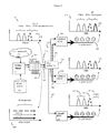
- FIG. 5 shows how one embodiment (here the CCAP option is shown) of the invention's distributed cable modem termination system, working with an advanced CMTS at the cable plant, can distribute a greater effective amount of downstream data to various CATV cables serving multiple users in different neighborhoods.
- FIG. 6 shows additional details of how some embodiments of the CMRTS fiber nodes may be constructed and operate in the CCAP option.
- FIG. 7 shows additional details of the CMRTS fiber nodes.
- FIG. 8 shows an overview of how the distributed cable modem system may be configured by way of “virtual shelf” software that controls the operation and data flow of the system's CMTS and CMRTS devices.
- FIG. 9 shows how an alternative embodiment of the invention's distributed cable modem termination system, working with a prior art CMTS, can distribute a greater effective amount of downstream data to various CATV cables serving multiple users in different neighborhoods.
- FIG. 10 shows additional details of how an alternative embodiment of the CMRTS fiber nodes may be constructed and operate.
- the invention may be a distributed Cable Modem Termination System (CMTS) for a Hybrid Fiber Cable (HFC) network.
- CMTS Cable Modem Termination System
- HFC Hybrid Fiber Cable
- the system will work essentially independently of the CMTS at the cable plant, and will essentially act to supplement the functionality of prior art CMTS by adding a minimal amount of new equipment at the cable plant.
- this new equipment at the cable plant cable will mainly consist of a Level 2/3 switch, a virtual shelf management system (to be described), and appropriate MAC and PHY devices to send and receive data along optical fibers.
- the prior art cable plant CMTS continues to operate as before, with the one exception that the cable operator should provide for some empty channels in order to provide space for the new channels provided by the invention. Alternatively if no legacy operation is desired, then the prior art cable plant CMTS may not be needed at all.
- parts of the system will be embedded into an advanced CMTS head with at least a legacy packet switch, a legacy MAC (Media Access Control), and a legacy PHY (Physical Layer) capable of sending and receiving data from a layer 2-3 switch to a legacy end of a legacy optical fiber as at least a plurality of legacy digitally encoded analog QAM waveforms (legacy optical signals).
- a legacy packet switch a legacy MAC (Media Access Control)
- a legacy PHY Physical Layer
- the CMTS head may also have a second MAC and a second PHY capable of sending and receiving data from the layer 2-3 switch to either the first end of the legacy optical fiber, or the first end of a CCAP optical fiber.
- the second PHY may send and receive data using an alternate wavelength and often an alternative data transmission protocol such as an Ethernet protocol, although QAM waveforms may also be used).
- the legacy wavelength is 1310 nm
- the CCAP wavelength may be 1550 nm.
- the CCAP wavelength may be set as desired, such as at 1310 nm. In general, if two different wavelengths are used, they will be spaced apart enough to avoid crosstalk, often with spacing of 20 nm, 50 nm, 100 nm, or more depending upon the bandwidth of the optical signals.
- the second MAC and second PHY can send this data out using the first end of a different CCAP optical fiber.
- the second MAC and second PHY which are used for CCAP purposes, are designated as the CCAP optical signals.
- this CCAP signal will often also be designated as “Fiber 2 ”, and drawn as a separate fiber, regardless of if the CCAP signal is actually being sent on a CCAP fiber, or simply on a CCAP wavelength on the legacy fiber, or on the same legacy wavelength on the legacy fiber (permissible when no legacy optical fiber signals are being transmitted).
- the system will also usually have one or more remote CMRTS fiber node(s) located at the second end(s) of the legacy optical fiber.
- second end(s) will also be used to designate the distal (furthest away from the CMTS and the cable plant) end of an optical fiber, even after splitting.
- One component of the CMRTS fiber node(s) may be a legacy “dumb” optical to RF (radio frequency) conversion device that directly converts any legacy optical signals (sent as QAM waveforms by the CMTS at the first end of the fiber) to a legacy set of RF signals.
- legacy optical to RF radio frequency
- These are typically designated as O/E or E/O converters, depending upon the direction of the electrical RF to fiber optic conversion.
- Another component of this CMRTS may be least one QAM modulator device capable of detecting and encoding selected portions of the CCAP optical signals into a CCAP set of RF QAM waveforms.
- This QAM modulator may be part of a CMRTS PHY unit, and the CMRTS may often have the corresponding MAC and packet switching capability, as well as an optional controller (e.g. microprocessor and associated software) to select portions of the CCAP optical signals and control the packet switching, MAC and PHY (including the CMRTS QAM modulators) as needed.
- the CMRTS will also usually contain at least one software controllable switch that can be remotely directed to select at least some of the CCAP optical signals (selected CCAP optical signals) and direct said at least one CMRTS QAM modulator device to encode the selected CCAP optical signals into a CCAP set of RF QAM waveforms at a selected set of frequencies (remotely generated QAM signals).
- this software controllable switch will be part of, or be controlled by, the optional controller.
- the CMRTS may also contain at least one remotely software controllable RF packet processor capable of detecting upstream data carried by CATV RF upstream signals generated by at least one cable modem, and digitally repackaging and said upstream data and retransmitting said upstream data as a (third) upstream digital optical fiber signal.
- the software controllable switch(s) and/or software controllable RF packet processor(s) are capable of being remotely configured by software to implement at least a subset of the standard DOCSIS upstream and downstream functions (here standard DOCSIS is DOCSIS 3.0 as per the filing date of Ser. No. 12/692,582).
- standard DOCSIS is DOCSIS 3.0 as per the filing date of Ser. No. 12/692,582
- TDMA Time Division Multiple Access
- SCDMA DOCSIS Synchronous Code Division Multiple Access
- the various DOCSIS QAM modulation modes such as 16-level, 32-level, 64-level, 128-level, and 256-level QAM modulation modes may be implemented.
- the CMRTS may, at the fiber node, generate QAM channels carrying digital broadcast video, digital video on demand, digital High Definition (HD) video, Voice data, and DOCSIS (data) channels.
- additional functions that were not yet officially part of the DOCSIS 3.0 specification i.e. non-DOCSIS functionality
- additional functions that were not yet officially part of the DOCSIS 3.0 specification i.e. non-DOCSIS functionality
- such as upstream data from various new models of non-DOCSIS standard set-top box gateways may also be implemented by the CMRTS.
- the CMRTS can be viewed as handling a superset of the DOCSIS 3.0 functions, because it is being used to extend the functionality of the HFC system beyond that of the standard DOCSIS 3.0 functions.
- the term “superset” is being used to denote the additional (non-standard DOCSIS 3.0) functionality.
- non-DOCSIS 3.0 functionality includes functionality to transmit various forms of digital video such as standard digital video, high definition HD digital video, and various forms of digital video upon demand.
- Both the software controllable switch(s) and software controllable RF packet processor(s) will often incorporate their own microprocessors or microcontrollers, as well as memory (such as flash memory, ROM, RAM, or other memory storage device) to incorporate software needed to operate the switches and processors, interpret command packets sent from the virtual shelf manager, and transmit data packets to the virtual shelf manager.
- memory such as flash memory, ROM, RAM, or other memory storage device
- the CMRTS also may often have a combiner device, or at least be attached to a combiner device (such as a Diplex device), that combines any legacy set of RF signals and the remotely generated QAM signals to produce a combined RF signal suitable for injection into a CATV cable connected to at least one cable modem.
- a combiner device such as a Diplex device
- this Diplex device may be external to the actual CMRTS unit, however when legacy operation is desired, the CMRTS unit will normally depend upon either an internal or external combiner (e.g. a Diplex device) for functionality.
- the system will also usually have a centralized computer system or computer processor running software (e.g. virtual shelf software) that controls many aspects of its function.
- software e.g. virtual shelf software
- the computer software that controls the functionality of the dispersed CMTS-CMRTS units of this invention will be referred to in the alternative as a “virtual shelf”.
- the “virtual shelf” could be viewed as running some sort of “Generic Control Protocol” or “GCP” that sends control plane information to manage the CMRTS units as slave devices.
- GCP Generic Control Protocol
- the commands sent by the virtual shelf or “GCP” would for example reach microprocessors or microcontrollers on the CMRTS units (slave units) and in the course of reconfiguring the operation of the CMRTS units, the state of the various registers on the microprocessors or microcontrollers would of course be altered (e.g. register reads, writes, or other standard processor register contents alterations commands as is standard in the art).
- This “virtual shelf” software will ideally manage the much higher complexity of the dispersed CMTS-CMRTS system in a way that will be easy to manage, and ideally sometimes almost transparent, to the cable plant, so that other systems in the cable plant can often handle the more complex data distribution properties of the invention's dispersed CMTS-CMRTS system as if the system behaved more like a simpler, prior art, CMTS system.
- one important function of the computer processor and “virtual shelf” software will be to select and control at least the CCAP optical signals and the remotely generated QAM signals. These will be managed in a way that, as will be discussed, greatly increases the amount of IP-on-demand data available for cable system users.
- the invention may be a remote CMTS fiber node (CMRTS) system for a Hybrid Fiber Cable (HFC) network.
- CMRTS CMTS fiber node
- This CMRTS portion of this system will typically (but not always) comprise a legacy optical to RF (radio frequency) conversion device that directly converts a legacy set of RF modulated optical fiber signals to a legacy set of CATV RF signals.
- the CMRTS portion will also often comprise at least one QAM modulator device capable of encoding selected portions of digitally encoded CCAP optical fiber signals into a CCAP set of RF QAM waveforms.
- the CMRTs portion will also often comprise at least one software controllable switch that can be remotely directed to select at least some of the CCAP optical fiber signals (selected CCAP optical signals) and direct the at least one QAM modulator device to encode certain selected CCAP optical signals into a CCAP set of RF QAM waveforms at a selected set of frequencies. These will be called remotely generated QAM signals.
- the CMRTS portion will also often comprise at least one remotely software controllable RF packet processor (and associated MAC and PHY units) capable of detecting upstream data carried by CATV RF upstream signals generated by at least one cable modem, digitally repackaging this upstream data and then retransmitting this upstream data back (often eventually usually back to the cable plant) as a third upstream digital optical fiber signal.
- the invention is a system because here, the at least one software controllable switch and/or the software controllable RF packet processor will usually be designed to be capable of being remotely configured by software to implement at least a subset of the standard DOCSIS 3.0 upstream and downstream functions.
- the CMRTS need not implement a full set of standard DOCSIS 3.0 functionality. This is because if any legacy operation is desired, at least some of the DOCSIS functionality that is ultimately delivered to the various cable modems on the various houses can be delivered by the directly converted (e.g. legacy) CATV RF signals obtained from the CMTS at the cable head.
- directly converted e.g. legacy
- the functioning of the at least one software controllable switch and the functioning of said at least one remotely software controllable RF packet processor are preferably controlled by a remote virtual shelf manager system, which will be discussed in more detail shortly.
- the invention may be a method of operating (and optionally enhancing the data carrying capacity) a hybrid fiber cable (HFC) network with a cable head, an optical fiber network, a plurality of optical fiber nodes, a plurality of individual CATV cables connected to the plurality of optical fiber nodes, and a plurality of individual cable modems, each with differing data requirements, connected each of said individual CATV cables.
- This method will usually (but not always) include transporting a legacy set of data from the cable head to the optical fiber nodes using a plurality of QAM waveforms that are capable of being directly injected into individual CATV cables by an optical to RF converter.
- RF QAM waveforms Direct conversion of the legacy waveforms is easy and simple because the shape of the waveforms remains the same, and only the underlying media (optical or RF) and frequency of the waveforms needs to be adjusted during the conversion process.
- These QAM waveforms will be called RF QAM waveforms or more specifically legacy RF QAM waveforms.
- the method will also usually include transporting a CCAP set of data from the cable head to the optical fiber nodes.
- this CCAP set of data will usually not be capable of being directly injected into individual CATV cables by an optical to RF converter (e.g. any waveform shapes would not be compatible). Rather, the method will instead usually convert a selected portion of this CCAP set of data into RF QAM waveforms at the optical fiber nodes.
- These remotely produced RF QAM waveforms from selected portions of the CCAP set of data will be called CCAP RF QAM waveforms.
- the method will then combine the legacy RF QAM waveforms with the CCAP RF QAM waveforms, and inject the combined RF QAM waveforms into individual CATV cables serving individual neighborhoods.
- the method will control this selection and any mixing process so that for each individual CATV cable (which may be a part of a group or plurality containing a number of other individual CATV cables), any legacy RF QAM waveforms and the CCAP RF QAM waveforms will be selected so that the combined RF QAM waveforms do not exceed the available bandwidth any of the individual CATV cables.
- the method will control the CCAP set of data and the selected portion of the CCAP set of data to satisfy (usually better satisfy than prior art methods) the differing data requirements for a number of different of cable modems.
- different individual CATV cables when considered in contrast to a group of multiple individual CATV cables, will generally carry differing CCAP RF QAM waveforms, where each differing CCAP RF QAM waveform will generally satisfy the unique data requirements for the various cable modems hooked up to the particular individual CATV cable.
- FIG. 1 shows an overall view of the various frequencies and data channels allocated for CATV ( 100 ).
- the lower frequencies such as 5-42 MHz, are allocated for use in transmitting data “upstream” from the individual cable modems back to the Cable Head or Cable plant ( 102 ).
- upstream data is transmitted using a time-share TDMA (Time Division Multiple Access) manner in which individual cable modems are allocated certain times on roughly 2 MHz wide QAM channels to transmit data.
- TDMA Time Division Multiple Access
- frequencies space, bandwidth
- DOCSIS services 108
- voice, on-demand video, IP, and other information again generally as a series of 6 MHz wide QAM channels.
- cable bandwidth is seldom used at present, although future services may extend further into this region.
- the invention is indifferent as to the use of higher frequency cable bandwidth and channels. If available, the invention may use them. If not available, the invention will cope with existing cable frequencies and bandwidth.
- CATV cable thus has a finite bandwidth of at most about 100-200 QAM channels.
- this bandwidth is used to serve a large amount of different customized types of data to a large amount of different subscribers, this bandwidth quickly becomes exhausted.
- FIG. 110 A drawing showing how the CATV spectrum allocation can be described in a more simplified diagram is shown below ( 110 ), ( 120 ). This diagram will be used in various figures to more clearly show some of the CATV spectrum allocation aspects of the invention. Note of course that as different RF QAM channels and other RF channels change, then the spectrum of the CATV RF signals will also change.
- the “upstream” segment ( 112 ) is an abstraction of all upstream channels, including both presently used upstream channels in the 5-42 MHz region, as well as present and future higher frequency upstream DOCSIS channels.
- the “video” segment ( 114 ) is an abstraction of both the almost obsolete analog TV FDM channels, as well as the standard “digital video” channels, as well as the projected digital video channels that will occupy the soon to be reclaimed analog bandwidths once the analog channels are phased out. Segment ( 114 ) also represents other standard digital radio and FM channels, and in general may represent any standardized set of downstream channels that will usually not be customized between different sets of users and neighborhoods.
- the “DOC1” channel ( 116 ) may be (depending upon mode of use) either a full set or subset of present or future DOCSIS channels.
- DOC1 often represents a basic set of DOCSIS services that would be made available for fallback use by neighborhoods in the event of a failure of the higher performance IP/on demand or DOC2 channels ( 118 ).
- the DOC1 QAM channels are normally chosen so as to not exhaust the full bandwidth of the CATV cable, so that at least some remaining QAM channels are available for the neighborhood customized DOC2 channels.
- IP/On-demand or DOC2 channel ( 118 ) is essentially (depending upon mode of use) the remaining available downstream bandwidth on the CATV cable, and is usually reserved for transmitting neighborhood specific data (IP/On-demand data), often transported by a different communications media (such as a CCAP fiber or CCAP wavelength, and often by a non-QAM protocol) from the cable head to individual neighborhoods.
- a different communications media such as a CCAP fiber or CCAP wavelength, and often by a non-QAM protocol
- the sum of the DOC1 ( 116 ) and IP/On demand ( 118 ) channels sent by optical fiber to a group of neighborhoods can never exceed the effective bandwidth (i.e. the carrying ability of the CATV cable and the ability of cable modems to detect the cable RF signal) of the CATV cable.
- the sum of the DOC1 ( 116 ) and IP/On-demand ( 118 ) channels sent by optical fiber to a group of neighborhoods will often exceed the effective bandwidth of the CATV cable on a group of neighborhoods basis, although the sum of DOC1 ( 116 ) and IP/On-demand ( 118 ) will never exceed the effective bandwidth of the CATV cable on a per-neighborhood basis.
- FIG. 2 shows a simplified version of how prior art HFC systems ( 200 ) transmit data from the cable head ( 202 ) to different optical fiber nodes ( 204 ) serving different neighborhoods ( 206 ).
- Each neighborhood will typically consist of up to several hundred different houses, apartments, offices or stores ( 208 ) (here referred to generically as “houses”), each equipped with their own cable modems (not shown).
- houses here referred to generically as “houses”
- the cable head will obtain standardized media content ( 210 ) (such as a standard assortment of analog and digital video channels) from one set of sources, and also obtain more individualized data ( 212 ), such as video on demand, IP from the Internet, and other individualized data from other sources.
- This data is compiled into a large number of different QAM (and at present also FDM) modulated CATV broadcast channels at the CMTS shelf ( 214 ).
- This CMTS ( 214 ) typically located at the cable head as well, will often have a number of different blade-like line cards ( 216 ). These line cards transmit the signals by optical fibers ( 218 ) to different areas (groups of neighborhoods).
- the FDM modulated CATV broadcast signal is an analog signal (for older style analog televisions), and even the QAM signal, although it carries digitally encoded information, is itself an analog signal as well.
- both FDM and QAM waveforms (signals) usually have a bandwidth of about 6 MHz in the US.
- the FDM and QAM signals are shown as having a center wavelength and bandwidth in order to emphasize the essentially analog nature of this signal, even when carrying digital information.
- These analog signals can be carried by optical fibers, and converted into RF signals for the CATV cable part of the network, using very simple and inexpensive equipment.
- typical HFC networks actually have a rather complex topology. Rather than sending one optical fiber from the CMTS to each different neighborhood, typically optical fibers will serve multiple neighborhoods. To do this, the signal from the CMTS side optical fiber will at least usually be split (by an optical fiber splitter ( 220 )) into several different optical sub-fibers ( 222 ), and each sub-fiber in turn will in turn carry the signal to a different fiber optic node (fiber node, FN) ( 204 ).
- fiber node fiber node
- the optical signal is converted into a CATV radio frequency (RF) signal and sent via CATV cables ( 226 ) to individual cable modems at individual houses ( 208 ) in each neighborhood.
- RF radio frequency
- CATV cable ( 226 ) is connected to all of the houses ( 208 ) in the neighborhood ( 206 ), if the cable modem in one house in a neighborhood wants to request customized on-demand video or IP, then all of the houses in the neighborhood that are attached to that particular CATV cable will actually receive the customized signal. Although only the cable modem associated with the requesting house (not shown) will actually tune into and decode the requested signal, it should be appreciated that if each individual house in the neighborhood were to simultaneously request its own customized set of video on demand or IP at the same time, the limited bandwidth of the CATV cable would be rapidly saturated. As a result, there is an upper end to the amount of customized data that can be transmitted to each house, beyond which bandwidth must be limited and/or requests for additional customized data will have to be denied.
- the different blades or line cards ( 216 ) of the CMTS shelf ( 214 ) located at the cable head ( 202 ) can send different customized IP/on-demand channels to different groups of neighborhoods, the granularity of this process is sub-optimal, because all individual neighborhoods connected to the same fiber splitter will get the same customized IP/on-demand signal. Given the limited bandwidth of the CATV cable, if all neighborhoods get the same signal, then the amount of data that can be sent to each individual neighborhood must, by necessity, be limited so as not to exceed the total available bandwidth.
- FIG. 3 contrasts the conversion process between the optical fiber ( 222 ) and the CATV cable ( 226 ) that occurs with a typical prior art fiber node ( 204 ), and with the invention's improved CMRTS fiber node ( 300 ). Here, for simplicity, only the downstream portion of the process is illustrated.
- the optical fiber ( 222 ) carries both the standardized video signals, and the analog QAM signal (that contains digital information) for both digital television and DOCSIS use (that can carry on demand video or IP data).
- “dumb” fiber node ( 204 ) simply converts the optical fiber's optical FDM or QAM analog signals into RF FDM or QAM signals and passes these signals to the CATV cable ( 226 ).
- the CATV cable ( 226 ) simply converts the optical fiber's optical FDM or QAM analog signals into RF FDM or QAM signals and passes these signals to the CATV cable ( 226 ).
- the standardized signal e.g. the standardized video channels
- the standardized signal e.g. the standardized video channels
- either a full set or subset of the DOCSIS QAM channels can (if legacy mode is desired) be carried by the “main” or legacy optical fiber channel, here designated as “Fiber 1 ”, and drawn as a thinner line since, in the present specification, legacy operation is deemphasized.
- Fiber 1 can often be the same fiber used to carry any legacy (prior-art) signals, and to emphasize this legacy mode (backwards compatibility) option of the invention, Fiber 1 will be designated by the same number ( 222 ).
- Fiber 1 ( 222 ) will carry the CATV spectrum as a series of optical waveforms that directly correspond to the RF QAM waveforms that will be injected into the CATV cable ( 120 ).
- either a subset, full set (here the present disclosure emphasizes the full set option), or superset of the DOCSIS QAM channels can also be carried by other physical media means, such as by a CCAP fiber, or by an alternate wavelength of light on the Fiber 1 , or (if no legacy signals are transmitted, by a legacy wavelength on the legacy Fiber 1 ).
- the media that carries this CCAP set of data will be designated as “Fiber 2 ”, and will be drawn as a thicker line ( 302 ) to emphasize that, in contrast to earlier disclosure Ser. No. 12/692,582, which was more focused on preserving some legacy operation for backward compatibility, when backward compatibility is less important or not desired, Fiber 2 may likely carry substantially more data than Fiber 1 , and may even carry all of the data.
- Fiber 2 could also transmit its data by optical QAM waveforms suitable for simple conversion to the RF QAM waveforms used on the cable (by perhaps just QAM modulating the same signal at a different frequency), there is no requirement that Fiber 2 in-fact use any type of QAM encoding at all. Often, Fiber 2 may transmit this supplemental data by standard gigabit Ethernet protocols.
- the Fiber 2 signal ( 304 ) is shown as a series of lines ( 306 ) to symbolize the fact, that for example, alternative digital methods of signal transmission may be used. Here each line represents the data that ultimately will be converted to a QAM signal and sent to a specific neighborhood.
- Fiber 1 ( 222 ) need not carry any customized (user specific) information, such as DOCSIS information ( 116 ), or IP/on-demand channels ( 118 ), at all.
- These customized channels can either be removed from Fiber 1 ( 222 ) (i.e. by filtering) or more usually, some or all of the customized IP/on-demand channels/DOCSIS will simply not be injected into Fiber 1 by the cable plant CMTS in the first place. The present disclosure generally favors this later option. Note again that if Fiber 1 isn't carrying anything, then of course it is totally available for use and in essence “Fiber 2 ” can be “Fiber 1 ”.
- Fiber 1 may carry the legacy standardized video channels ( 114 ), and some of the customized DOCSIS ( 116 ) or IP/On-demand-DOCSIS information ( 118 ), and this partial set of IP/On-demand-DOCSIS information can be sent to those users that are still being served by prior-art legacy “dumb” fiber nodes.
- the users served by the invention's improved CMRTS fiber nodes will be able to access the additional CCAP information sent by optical fiber 2 , GigE, or Fiber wavelength 2 ( 304 ).
- the fiber node's CMRTS unit will determine (or at least select with the aid of the virtual shelf) which set of customized data ( 308 ), ( 310 ), ( 312 ) its particular neighborhood requested, and retrieve this information from the Fiber 2 media ( 302 ).
- This information will then be QAM modulated and converted to the appropriate RF frequency, put onto a suitable empty IP/On-demand QAM CATV cable channel ( 314 ), ( 316 ), ( 318 ), and then sent by CATV cable to the neighborhood that requested that particular data.
- the particular cable modem from the house that requested that data can tune into this QAM channel and extract the data, while the other cable modems also attached to that cable will ignore the QAM channel and/or ignore the data.
- this method allows for much finer granularity, and a correspondingly higher rate of transmission of customized data.
- FIG. 4 shows that the invention may use a similar system and method to transmit a higher amount of data upstream as well.
- a limited amount of bandwidth 112
- the limited region from 5-42 MHz is shown ( 112 ).
- signals from multiple different fibers would be consolidated onto a single fiber ( 222 ), again raising congestion issues.
- the upstream data from each neighborhood ( 400 ), ( 402 ), ( 404 ) can be extracted, the QAM signal optionally decoded, the data put on an appropriate (empty) return channel (or an empty TDMA time slice of an appropriate return channel) ( 406 ), ( 408 ) ( 410 ), and sent back to the cable head by a less congested CCAP customized data transmission media, such as Fiber 2 ( 302 ).
- a less congested CCAP customized data transmission media such as Fiber 2 ( 302 ).
- FIG. 5 shows an example of the previously discussed CCAP option in which both the distribution of any legacy RF QAM channels produced by the head end CMTS, and the distribution of QAM channels produced by the CMRTS, are managed together in a more sophisticated system employing both CMRTS and a new type of higher functionality head end CMTS.
- the improved “smart” CMRTS fiber node ( 300 ) can transport a higher effective amount of customized user data.
- these improved “smart” CMRTS fiber nodes ( 300 ) are shown working in conjunction with an improved CMTS shelf ( 500 ) and improved CMTS line cards ( 502 ) at the cable head.
- an optical fiber ( 218 ) from the prior art CMTS unit ( 214 ) at the cable plant was split at by a fiber splitter ( 220 ) into three sub-optical fibers (all carrying the same data) ( 222 ), and these sub-optical fibers were then routed to three different neighborhoods. Because all optical fibers coming from the fiber splitter will carry the same data, the customized data is inefficiently sent to all three neighborhoods, even though only one house from one neighborhood may have actually requested the customized data.
- the limited carrying capacity (bandwidth) of the CATV customized IP/video on-demand channels can become saturated.
- the invention can operate by using an improved CMTS shelf ( 500 ) and improved CMTS line cards ( 502 ) capable of taking the incoming data, and partitioning the data into two transport media (e.g. optical fibers 1 ( 218 ) and un-split optical fiber ( 301 )).
- the “smart” CMRTS fiber nodes ( 300 ) of the invention (usually after splitter ( 220 ) further splits optical fiber 1 and optical fiber 2 into sub-fibers ( 222 ), ( 302 )) can now convey a much higher amount of data.
- the invention can operate by using an improved CMTS shelf ( 500 ) and improved CMTS line cards ( 502 ) need not partition the data into two transport media (e.g. optical fibers 1 ( 218 ) and un-split optical fiber ( 301 )) because there is no need for the legacy data channels.
- two transport media e.g. optical fibers 1 ( 218 ) and un-split optical fiber ( 301 )
- the different CMRTS fiber nodes can customize and optimize the DOCSIS or other signals to and from the cable serving that particular neighborhood to better serve that neighborhood, and do so in a way that is much less constrained by overall cable bandwidth.
- the “smart” CMRTS fiber node ( 300 ) retrieves additional data ( 304 ) from Fiber 2 ( 302 ); QAM modulates this additional data, and puts it onto a suitable empty QAM CATV cable channel ( 118 ).
- neighborhood 1 has requested IP/On-demand data ( 312 ). This is selected by the neighborhood 1 CMRTS ( 300 ) (often with the aid of the virtual shelf manager system to be discussed), QAM modulated by the CMRTS, and put onto the cable ( 226 ) serving neighborhood 1 as IP/On-demand signal or waveform ( 316 ) in the IP/On-demand channel(s) ( 118 ). Similarly neighborhood 2 has requested IP/On-demand data ( 310 ). This is selected by the neighborhood 2 CMRTS ( 300 ), QAM modulated by the CMRTS, and put onto the cable serving neighborhood 2 as IP/On-demand signal or waveform ( 318 ).
- the QAM channel or frequency ( 318 ) may occupy the exact same channel(s) ( 118 ) as signal ( 316 ). Thus more data has been transmitted, while at the same time, the limited bandwidth of the CATV cables serving the two neighborhoods has not been exceeded.
- the empty QAM CATV cable channel ( 118 ) becomes available to carry alternate types of data to that neighborhood.
- the limited carrying capacity of the CATV cable can instead be focused on the needs of that particular neighborhood.
- neighborhoods 1 and 2 are served by the invention's improved “smart” CMRTS fiber nodes ( 300 ).
- neighborhood 3 is only served by a prior art “dumb” fiber node ( 204 ).
- the Improved CMTS shelf ( 500 ) and CMTS line card ( 502 ) may elect to send at least a subset of the DOCSIS QAM channels ( 116 ) (here shown as DOC1), needed by neighborhood 3 .
- the improved CMTS ( 500 ) and CMTS line cards ( 502 ) have loaded the customized data requested by neighborhoods 1 and 2 onto Fiber 2 ( 302 ) ( 304 ) ( 312 ), ( 310 ).
- Fiber 2 will usually be routed to all neighborhoods, and indeed may of course simply be Fiber 1 using an alternative wavelength and optionally a different protocol. Again if no legacy operation is desired, Fiber 2 can be Fiber 1 working on any desired wavelength.
- the system's effective ability to deliver customized data to neighborhoods 1 and 2 , served by the improved “smart” CMRTS fiber nodes ( 300 ) and improved CMTS ( 500 ), ( 502 ) has substantially increased, because the IP/On-demand channels can be customized with data specific to each neighborhood.
- backward compatibility can be preserved (when desired) because neighborhood 3 , which still uses a prior art dumb fiber node 3 ( 204 ) can continue to make use of the DOCSIS subset channels transmitted by Fiber 1 ( 222 ).
- FIG. 6 shows additional details of how the “smart” CMRTS fiber nodes ( 300 ) may operate in conjunction with an improved cable head CMTS ( 500 ) and improved CMTS line cards ( 502 ). For simplicity, again primarily the downstream portion of the system is shown.
- the CMRTS fiber nodes ( 300 ) often (e.g. when legacy mode operation is desired) will have a simple optical to electric (O/E) ( 600 ) converter to convert the main (legacy, standardized) CATV analog (FDM and QAM) data/waveforms ( 120 ) optically transmitted by Fiber 1 into an RF signal.
- O/E optical to electric
- this O/E converter is an optical to RF (radio frequency) conversion device that directly converts a legacy set of RF modulated optical fiber signals to a legacy set of CATV RF signals.
- the CMRTS fiber nodes ( 300 ) will often also have an electric/optical (E/O) ( 602 ) converter to take the upstream RF data from the CATV cable, and convert it to an optical signal suitable for sending back to the cable farm by either Fiber 1 (not shown) or Fiber 2 as desired as legacy upstream signals.
- E/O electric/optical
- this E/O converter is a RF (radio frequency) to optical conversion device that directly converts a legacy set of upstream CATV RF signals to RF modulated optical fiber signals and sends said RF modulated optical fiber signals upstream relative to the CMRTS unit when legacy operation is desired.
- the CMRTS fiber node ( 300 ) will also contain a CMRTS unit ( 604 ) that will take the customized (e.g. CCAP) IP/on-demand data signal ( 304 ) from Fiber 2 ( 301 ), ( 302 ), QAM modulate this data to an appropriate empty CATV RF QAM channel ( 118 ), and transmit this customized data onto the CATV cable ( 226 ).
- a CMRTS unit 604 that will take the customized (e.g. CCAP) IP/on-demand data signal ( 304 ) from Fiber 2 ( 301 ), ( 302 ), QAM modulate this data to an appropriate empty CATV RF QAM channel ( 118 ), and transmit this customized data onto the CATV cable ( 226 ).
- the legacy RF converted main CATV analog (QAM channels) signal ( 114 ), ( 116 ) from fiber 1 (if any) ( 218 ), ( 222 ), and any frequency shifted customized IP/on-demand QAM channel ( 318 ) from fiber 2 ( 301 ), ( 302 ), ( 312 ), are combined if needed (for example by using a Diplex unit ( 606 ) located either inside or outside of the CMRTS fiber node ( 300 )), and the full reconstituted CATV signal containing both the legacy standard CATV video ( 114 ) and DOCSIS CATV subset ( 116 ), and the extended IP/On-demand QAM modulated data ( 318 ) is then sent out to the various houses in the neighborhood using the CATV cable ( 226 ).
- a Diplex unit 606
- the CMTS ( 500 ) and improved CMTS line cards ( 502 ) may be optionally configured with both packet processors ( 610 ), and MAC ( 612 ) and PHY ( 614 ) devices or functionality to transmit legacy standard CATV analog, QAM, and DOCSIS signals onto the legacy (main) optical fiber 1 .
- the same line cards may also be configured with packet processors ( 616 ), MAC ( 618 ) and PHY ( 620 ) functionality to transmit supplemental (e.g. CCAP) IP/On-demand extended DOCSIS data on optical fiber line 2 or fiber wavelength 2 .
- supplemental e.g. CCAP
- the Fiber 2 CCAP extended data may often be encoded by an entirely different (non-QAM) methodology ( 304 ).
- the MAC ( 618 ) and PHY ( 620 ) for Fiber 2 can be different (e.g. follow standard GigE protocols) from the MAC ( 612 ) and PHY ( 614 ) optionally used for optional Fiber 1 .
- Fiber 1 and Fiber 2 signals transmitted and received by the improved line card will vary depending upon what sort of fiber nodes are connected downstream (southern end) to the line card ( 502 ).
- the CMTS line card operates in full legacy mode and would only transmit on Fiber 1 , and the functionality of that particular CMTS line card would be backward compatible with prior art CATV DOCSIS equipment and fiber nodes. That is, Fiber 1 ( 218 ), ( 222 ) would transmit the full set of DOCSIS channels, and Fiber 2 ( 301 ), ( 302 ) will transmit nothing because there are no CMRTS fiber nodes ( 300 ) available to listen to the Fiber 2 data.
- Fiber 1 would only be used for transmitting standard video channels ( 114 ), or not used at all for any legacy signals.
- Fiber 1 is free and available to use for Fiber 2 purposes
- This alternative scheme would maximize the number of vacant QAM channels on the CATV cable, and thus allow the highest amount of customized data to be sent to the houses on that particular stretch of cable. This again is the preferred mode of operation explored in more detail in the present disclosure.
- the improved CMTS ( 500 ) and CMTS line card ( 502 ) should ideally elect to transmit and receive standard (legacy) video channels ( 114 ) and a subset of DOCSIS ( 116 ) information to and from neighborhood 3 (served by the “dumb” fiber node), using Fiber 1 to continue giving adequate service to neighborhood 3 .
- the improved CMTS ( 500 ) and CMTS line card ( 502 ) should ideally keep some DOCSIS QAM channels vacant on legacy Fiber 1 .
- the “smart” CMRTS fiber node ( 300 ) which may be instructed by outside commands (to be discussed from the virtual shelf manager system) will then determine or at least select what GigE data ( 304 ) transmitted by Fiber 2 ( 302 ) is needed by its particular neighborhood, QAM modulate it, and distribute it to its neighborhood as CCAP RF QAM waveforms on the empty QAM channel.
- data ( 312 ) has been QAM modulated and transmitted as CCAP RF QAM waveform or data ( 318 ).
- the same empty QAM channel frequency can transmit one set of data to the houses in neighborhood 1 , and a different set of data to on the same empty QAM channel frequency to the houses in neighborhood 2 .
- CMTS complementary metal-oxide-semiconductor
- CMRTS fiber nodes 300
- the functionality of the improved CMTS ( 500 ) and CMTS line cards ( 502 ), as well as usually the functionality of the CMRTS fiber nodes ( 300 ) is extended by use of additional “virtual shelf” network management computers, controllers, and software.
- a unified network management system (exemplified by, for example, the ConfD management system provided by Tail-f incorporated) is added to the improved CMTS ( 500 ) and line card ( 502 ) to unify the network and CMTS hardware and virtualization layer, provide operating system services, manage middleware, and configure the system to use the proper networking protocols.
- all or at least much network configuration data is stored on a database in or connected to the CMTS manager, and the configuration of the network is controlled by a process in which the management software (ConfD) communicates over IPC (sockets) or other control plane protocol with apps that control the function of various packet processors, MAC, and PHY devices on the improved CMTS and CMRTS units.
- a computer or processor and associated software memory are shown directly controlling the operation of an improved CMTS unit ( 500 ) by way of various other controllers ( 624 ), ( 626 ) located in the improved CMTS backbone ( 627 ) and line cards ( 502 ).
- the communications between this “virtual shelf manager” ( 622 ) and the local controller processors ( 624 ), ( 626 ) are shown as dashed lines ( 628 ).
- the virtual shelf manager may also control the operation of a level 2/3 switch ( 629 ) and/or other devices that connect the improved CMTS unit to the media content ( 210 ), Internet IP/On-demand data or “cloud” ( 212 ), and other services provided by the cable head ( 202 ).
- the virtual shelf manager may often also manage the configuration of the various “smart” CMRTS fiber nodes ( 300 ), often by communicating with controllers and applications software embedded with the CMRTS fiber nodes (not shown).
- the CMRTS fiber node ( 300 ) to virtual shelf manager ( 622 ) communication will often be done by various signals and signal protocols communicated by optical fibers 1 or 2 .
- socket based inter-process communication (IPC) protocols are used.
- Other control plane protocols may also be used.
- CMTS shelf This enables the configuration of the CMTS shelf, and indeed the overall network, to be rapidly reconfigured to meet the ever changing network model generated by the invention. Often it will be convenient to store this network configuration, as well as the properties of the various network devices, in a configuration database ( 630 ) and configuration database memory device (not shown).
- FIG. 7 shows more details of the CMRTS fiber node ( 300 ) (here shown without the optional diplex unit and/or signal combiner ( 606 ) (e.g. a diplex RF signal combiner device) and the CMRTS unit ( 604 ).
- the CMRTS unit of the CMRTS fiber node will typically comprise a first QAM-RF packet processor ( 700 ) with MAC and PHY units that convert the downstream data on Fiber 2 to a plurality of radiofrequency (RF) QAM waveforms (channels) and output this data downstream ( 702 ) to the local CATV cable.
- RF radiofrequency
- the CMRTS fiber node may optionally also usually have an Optical to electrical converter ( 600 ) capable of directly converting the CATV waveforms sent on Fiber 1 to RF CATV waveforms suitable for injecting into cable ( 226 )
- This CMRTS unit may also optionally comprise a CCAP RF-upstream packet processor ( 704 ) that will read the upstream RF signals (data) sent by cable modems connected to the local CATV cable ( 706 ), and convert this upstream data to appropriate Ethernet or other data communications protocols suitable for communicating this cable modem data back upstream to the improved CMTS ( 500 ) at the cable head or cable plant by way of Fiber 2 .
- a CCAP RF-upstream packet processor 704
- This upstream data sent by cable modems connected to the local CATV cable ( 706 ), and convert this upstream data to appropriate Ethernet or other data communications protocols suitable for communicating this cable modem data back upstream to the improved CMTS ( 500 ) at the cable head or cable plant by way of Fiber 2 .
- This RF-upstream packet processor is optional because alternatively (for legacy backward compatibility) the upstream data sent by the cable modems may optionally returned to the CMTS by simply taking the upstream RF signal ( 708 ), running it through an electrical to optical converter ( 602 ), and transmitting it back to the CMTS by way of Fiber 1 ( 222 ).
- any O/E and E/O converters ( 600 ), ( 602 ) may be remotely controlled by the virtual shelf manager ( 622 ) by way of suitable controllers (often microprocessors), and local applications software (Apps) that intercept control plane data from the virtual shelf manager via Fiber 1 ( 222 ) or Fiber 2 ( 302 ), and receive and send commands, often by way of a specialized control plane communications protocol such as the previously discussed sockets protocol or other control plane.
- controllers often microprocessors
- Apps local applications software
- the CMRTS unit ( 604 ) will normally comprise a data switch, such as a DOCSIS Level 2 forwarder ( 710 ), at least one controller (often a microprocessor and associated software, not shown), various QAM modulators ( 712 ) to take the CCAP DOCSIS data and/or other IP/on-demand data from Fiber 2 ( 302 ) and convert, QAM modulate, and frequency shift the data as needed to fit into suitable empty CATV channels as CCAP RF QAM waveforms.
- a data switch such as a DOCSIS Level 2 forwarder ( 710 ), at least one controller (often a microprocessor and associated software, not shown), various QAM modulators ( 712 ) to take the CCAP DOCSIS data and/or other IP/on-demand data from Fiber 2 ( 302 ) and convert, QAM modulate, and frequency shift the data as needed to fit into suitable empty CATV channels as CCAP RF QAM waveforms.
- CMRTS unit may employ a controllable clock generator ( 714 ) to control the frequency and timing of the QAM channels, as well as variable gain amplifier (VGA) units ( 716 ), ( 718 ) to help the PHY portions of the units manage the analog processes in converting signals back and forth between the CMRTS unit ( 300 ) and the cable RF signals.
- VGA variable gain amplifier
- the DOCSIS Level 2 forwarder ( 710 ) switches, and the switches that control the QAM modulators ( 712 ) and analog to digital (A/D) units ( 720 ) may be remotely controlled by the virtual shelf manager ( 622 ) by local (embedded) controllers (often microprocessors) and associated applications software by commands to and from the Virtual Shelf software. As before, often these commands may be sent over the same Fiber 1 or Fiber 2 pathways normally used to transmit other data, and again may use socket based inter-process communication (IPC) protocols or other control plane protocols.
- IPC inter-process communication
- the return process for processing upstream data can implement the earlier electronic to optical (E/O) converters and send the upstream signals back with essentially no modification other than the conversion to light wavelengths.
- the upstream process may be an upstream version of the invention's previously discussed downstream processes.
- variable gain amplifier (VGA) units ( 718 ) will convert the incoming upstream RF signal from the local neighborhood CATV cable into a signal which is then tuned into and digitized by the clock generator and A/D converter, and then forwarded by the DOCSIS Level 2 forwarder or other switch ( 710 ) towards the cable plant, often using Fiber 2 ( 302 ) so as to allow greater amount of upstream data to be sent.
- the DOCSIS Level 2 forwarder and conversion circuitry ( 710 ) may be controlled by commands from the Virtual Shelf software.
- FIG. 8 shows more details of how the virtual shelf manager ( 622 ) and the configuration database ( 630 ) (previously shown in FIG. 6 ) may control the functionality of most or all of the plurality of CMRTS fiber nodes ( 300 ), improved CMTSs ( 500 ) and CMTS line cards ( 502 ), and optionally other active nodes and switches in the HFC network system.
- the virtual shelf manager software ( 622 ) is shown running as a module of a broader CMTS manager software package ( 800 ); however it also may be run as a standalone package.
- the CMTS manager software ( 800 ) which will often be run on one or more computer processors which may be located at the cable head or other convenient location, will often be based on network configuration management software ( 802 ).
- network configuration management software ( 802 ) also called the Operational Support Systems (OSS) software
- OSS Operational Support Systems
- ConfD software such as ConfD
- NETCONF management agents may include NETCONF management agents, SNMP agents, Command Line Interfaces (CLI), Internet (Web) interfaces, and other agents/interfaces as desired.
- CLI Command Line Interfaces
- Web Internet
- the virtual CMTS shelf software that may be used to control the status of the various CMTS line cards ( 502 ) and CMRTS fiber nodes ( 300 ) will often interact with a network configuration database ( 630 ) run under the control of this network configuration software ( 802 ).
- the virtual CMTS shelf software will in turn send commands (e.g. control plane commands) out to most or all of the various remote CMRTS fiber nodes, as well as control the operation of the CMTS ( 500 ) at the cable head (cable plant), and other devices as desired.
- IPC inter-process communication
- packets ( 804 ) which may be sent over the same communications lines used to send the data plane CATV and DOCSIS data, such as any Fiber 1 ( 218 ) and Fiber 2 lines ( 302 ).
- controllers running various types of application software (Apps) in the plurality of remote packet processors ( 700 ), ( 704 ) in the remote CMRTS fiber nodes ( 300 ) can listen for appropriate commands from the virtual shelf manager ( 622 ), and adjust the operation of the CMRTS packet ( 700 ), ( 704 ) processors accordingly.
- These CMRTS fiber nodes can also transmit their status back to the virtual shelf manager using the same or different data plane protocols
- the device configuration database ( 630 ) of the virtual shelf manager system will often have multiple data fields, including fields that contain the identification code and/or addresses of the various CMRTS units in the network (CMRTS identifier fields).
- the database will also usually have information on the status of the various cable modems connected to the various CMRTS units, including the cable modem identification data (cable modem identification data fields) and the privileges of the various users that are associated these various cable modems. For example, one user may have privileges to access a broad array of services high bandwidth upload and download data, while another user may have limited access to a different set of services and more limited upload and download data privileges.
- Other functions that may be implemented include event logging, Authentication, Authorization and Accounting (AAA) support, DOCSIS Management Information BASE (MIBs) functions, etc.
- Other fields that normally will be in the database will include information as to user identification fields (user privilege fields), available DOCSIS channels, available IP addresses, instructions for how to remotely configure the various CMRTS software controllable switches, and instructions for how to remotely configure the various CMRTS software controllable RF packet processors.
- user identification fields user privilege fields
- available DOCSIS channels available IP addresses
- instructions for how to remotely configure the various CMRTS software controllable switches instructions for how to remotely configure the various CMRTS software controllable RF packet processors.
- the Virtual shelf manager and configuration database will usually be run on a computer system with at least one microprocessor, as well as standard hardware and software, such as MAC and PHY units, that will enable the virtual shelf manager to send and receive data packets (often through the IPC protocol or other data plane protocol) to the various remote CMRTS units on the network.
- microprocessor as well as standard hardware and software, such as MAC and PHY units, that will enable the virtual shelf manager to send and receive data packets (often through the IPC protocol or other data plane protocol) to the various remote CMRTS units on the network.
- MAC and PHY units standard hardware and software
- the OSS software can inform the virtual shelf manager software about the privileges, certificates, and encryption keys assigned to the various users.
- the OSS can also set policies or allocation limits regarding the frequency and bandwidth that will be assigned to the various channels.
- the OSS can also respond to queries from the virtual shelf manager when new modems are detected.
- the OSS can further take statistical data collected by the virtual shelf manager, such as packets transmitted and received, volume of data, and use this information for billing and network management purposes.
- the cable modem will send an upstream DOCSIS signal ( 226 ) to the CMRTS ( 604 ).
- the RF-up packet processor ( 704 ) in the CMRTS ( 604 ) will in turn collect the information relating to the cable modem identification number, and other relevant parameters, repackage the data in a digital format, and send it back upstream to the virtual shelf manager system on the fiber GigE link ( 302 ).
- the virtual shelf manager system ( 622 ) will look up the cable modem identification data in the device configuration database ( 630 ), and determine the privileges of the user associated with said cable modem identification data, and depending upon the value of the user privilege field, available DOCSIS channels, and available IP addresses, send data packets to the CMRTS ( 700 ) unit, often by way of the IPC protocol ( 804 ) that controls that particular cable modem or other control plane protocol.
- These data packets will interact with applications (e.g. App 1 , App n) and configure the software controllable switch(s) on the CMRTS unit ( 700 ), to configure the software controllable switches on the QAM-RF packet processor ( 700 ) and the cable modem available IP addresses so as transmit downstream data to the cable modem on a first available DOCSIS channel.
- the data packets will also configure the software controllable RF packet processor ( 704 ) to receive upstream data from the cable modem on a CCAP available DOCSIS upstream channel and IP address and retransmit the upstream data as a third upstream digital optical fiber signal ( 302 ).
- the virtual shelf manager ( 622 ) will handle IP addresses for the cable modems through the proxy Dynamic Host Configuration Protocol (DHCP) service, or other method.
- DHCP Dynamic Host Configuration Protocol
- one particular advantage of this approach is that in some embodiments, it can be configured to enable excellent forward and backward compatibility.
- the same CMRTS units can be used in present HFC networks, HFC networks using conventional CMTS units (option one), or advanced HFC networks using advanced CMTS units (option two).
- CMTS units optional one
- advanced HFC networks using advanced CMTS units optional two
- higher levels of functionality can be achieved by dropping the backward compatible (legacy) mode.
- the network may wish to optimize the performance of this branch of the network by, for example, now configuring the CMTS line card ( 502 ) that sends a signal to Fiber splitter “n” ( 220 ) to now stop sending the DOC1 ( 116 ) channel on Fiber 1 ( 218 ), ( 222 ).
- CMTS line card 502
- Fiber splitter “n” 220
- DOC1 116
- Fiber 1 218
- 222 By no longer transmitting the DOC1 channel on Fiber 1 , additional empty channels (frequencies) are created on this branch of the HFC network that instead can be used to transmit additional IP/On-demand data by way of Fiber 2 ( 301 ), ( 302 ).
- the virtual shelf manager ( 622 ) will send commands to the appropriate Level 2/3 switch ( 629 ) and CMTS line card ( 502 ) reconfiguring the CATV Video and DOCSIS packet processor ( 610 ), CATV MAC ( 612 ), and CATV PHY ( 614 ) to no longer transmit the DOC 1 channel.
- the virtual shelf manager will also send commands to the appropriate Level 2/3 switch ( 629 ); GigE (Gigabyte Ethernet) packet processor ( 616 ), the GigE MAC ( 618 ), and the GigE PHY ( 620 ), to alternatively send the data that normally (e.g.
- the virtual shelf manager will also communicate with CMRTS fiber nodes 1 , 2 , and new CMRTS fiber node 3 ( 300 ) instructing the fiber nodes to look for the former DOC 1 data on Fiber 2 ( 302 ) using the CCAP QAM-RF packet processor ( 700 ) and/or the DOCSIS L2 forwarder ( 710 ) and use QAM modulator ( 712 ) to QAM modulate this DOC1 data, and send the data out on the empty DOC1 channel ( 116 ).
- the virtual shelf manager can now make better use of this formerly inefficiently used DOC 1 channel (frequency) because now it is used to send neighborhood specific data. Thus again, by dropping any requirement for legacy or backward compatibility, the system may be further improved.
- the improvement in flexibility increases the amount of data available to the system's users.
- the DOC1 QAM signal on the Doc1 channel (frequency) ( 116 ) was transmitted to all three fiber nodes to the cables in three different neighborhoods, regardless of if any cable modems hooked to CATV cable attached to a particular fiber node needed the data or not.
- “dumb” fiber node 3 ( 204 ) with “smart” CMRTS fiber node 3 ( 300 )
- the ability of the other neighborhoods to receive a broader array of customized IP/On-demand services has been increased.
- the utility of dropping all legacy mode operation is preferred, in some embodiments, retaining at least some legacy capability still can have some advantages. For example, further suppose that the CMRTS unit ( 604 ) in new CMRTS fiber node 3 ( 300 ) experiences an early mortality failure soon after installation. In this case, if the CMRTS fiber nodes retain some legacy capability (such as their O/E and E/O portions ( 600 ), ( 602 )). If this is done then CMRTS fiber node 3 can continue to operate, assuming also that some legacy signals are still sent from the head end. In this situation, the failed CMRTS fiber node 3 ( 300 ) can operate in fall-back “dumb” fiber node 3 ( 204 ) mode again.
- some legacy capability such as their O/E and E/O portions ( 600 ), ( 602 )
- the virtual shelf manager ( 622 ) can cope with this failure by simply either rolling back the changes that it just made, or resuming at least some level of legacy operation, and service to all three neighborhoods can continue (at the less capable prior level) while the failed new CMRTS fiber node 3 is serviced.
- FIG. 9 can be used both as an example of mixed legacy/CCAP mode in which the invention's CMRTS system is used to gradually upgrade a more conventional (legacy) CMTS HFC system, as well as an example of a HFC system operating in pure CCAP mode
- the CMTS shelf can be a standard (prior art) CMTS shelf ( 214 ), that has been configured by the cable operator to leave some QAM channels (DOCSIS channels) empty.
- DOCSIS channels QAM channels
- the data that is handled by the CMRTS units ( 604 ) in the CMRTS Fiber Node ( 300 ) is handled in a manner that is completely separate from the data handled by the standard CMTS shelf ( 214 ), which is simply passed back and forth from the local cables ( 226 ) in the various neighborhoods by the simple O/E ( 600 ) and E/O ( 602 ) devices in the CMRTS fiber node ( 300 ).
- the Internet/IP etc. data ( 212 ) destined for the various CMRTS units ( 604 ) are handled by a Level 2/3 switch that is independent of the CMTS ( 214 ), converted to an optical signal by the GigE MAC and PHY units discussed previously (not shown), and sent along fiber 2 ( 301 ) as before.
- the virtual shelf manager ( 622 ) interacts only with the Level 2/3 switch ( 629 ) and the associated CMRTS units ( 300 ), but not directly with the standard CMTS shelf ( 214 ).
- the virtual shelf manager ( 622 ) is controlled by the network configuration management software (OSS) ( 802 ).
- OSS network configuration management software
- FIG. 9 can also be used as an example of a completely non-legacy CCAP system as well. This can be done by merely removing the standard CMRTS shelf ( 214 ) and dumb optical fiber node 3 ( 204 )
- FIG. 10 shows additional details of how the “smart” CMRTS fiber nodes ( 300 ) may operate in conjunction with an optional prior art (legacy) cable head CMTS ( 214 ) and prior art CMTS line cards, or operate entirely in non-legacy CCAP mode.
- the function of the CMRTS is essentially the same, however the prior art CMTS shelf ( 214 ) (if used) will no longer intelligently manage its QAM channels, but will instead simply have some pre-allocated empty QAM channels that may be filled in by the CMRTS units.
- prior art CMTS shelf ( 214 ) may not even be present, in which case all QAM channels on the cable will initially be empty.
- optical fiber 1 ( 218 ) is totally free for use. If all of the optical fiber nodes are CMRTS fiber nodes ( 300 ), then the system will operate in a totally non-legacy, CCAP mode of operation where all data to and from the CMRTS fiber nodes ( 300 ) are carried by optical fiber 2 ( 301 ) (or optical fiber 1 218 , since 218 is empty). All data plane data and control plane data to and from the CMRTS fiber nodes is carried by optical GigE signals ( 304 ). This alternative configuration is often preferred because by giving up legacy mode, higher data transmission rates both upstream and downstream may be achieved.
- CMRTS examples used packet processors ( 700 ), ( 704 ), in an alternative and less preferred embodiment, one or more of these packet processors may not be needed.
- the signal may be simply passed through, or else modified by wave shaping, or modified by some other means.
- the CMRTS may not contain QAM modulators at all.
- QAM signals may be sent up and down the CCAP optical fiber (for example, to and from the cable head or optical fiber nodes closer to the cable head), and the CMRTS will simply employ frequency shifting circuitry to convert the CCAP optical fiber QAM signals to an appropriate empty CATV QAM channel (DOCSIS channel).
- DOCSIS channel CATV QAM channel
- the present disclosure speaks of transmitting video data, voice data, IP data and on-demand data to the various households, in alternative terms, this data may be alternatively described as being “data plane” information.
- this data may be alternatively described as being “data plane” information.
- the present disclosure speaks of transmitting information to control the operation of the CMRTS units (the invention's optical fiber nodes) using, for example commands transmitted by socket based inter-process communication (IPC) protocols and packets, these commands may be alternatively described as being “control plane” information. This information can for example alter the state of the CMRTS MAC and PHY units.
- IPC inter-process communication
- control plane commands will often be transmitted as data packets using the same optical fiber that also carries the “data plane” data packets, with the exception that digital formatted data packets are preferred, there is otherwise no limitation as to what format the control plane data packets must take, so long as the CMRTS units can distinguish the control plane data packets from the data plane data packets.
- the virtual shelf manager system which can reside at the head end, can be considered to be a master, and the various CMRTS units can be considered to be slaves to the virtual shelf manager system.
- the CMRTS units can also be described in alternative terms as well.
- the CMRTS units may be given alternative names such as modular CMTS units, network interface units, access points, and the like.
- the invention's head end and virtual shelf manager system can also be described in alternative terms.
- the head end can be described as the core for a modular cable modem termination system since the head end implements much of the core functionality of the system.
- the remote CMRTS units will often be controlled by microprocessors or microcontrollers, which optionally may be embedded in other circuits as desired. It should be evident to those skilled in the art that microprocessors and microcontrollers may be described at various levels of details. At a lower level, these devices may be described at the transistor or gate level, at a higher level, these devices may be described at the register and instruction set level, and so on. Thus although the present application generally speaks about commands that can be implemented by microprocessors or microcontrollers, it should be evident that this general type of teaching can be described in many alternative ways.
- CableLabs® is a trademark of Cable Television Laboratories, Inc.
Landscapes
- Engineering & Computer Science (AREA)
- Signal Processing (AREA)
- Multimedia (AREA)
- Computer Networks & Wireless Communication (AREA)
- Computer Security & Cryptography (AREA)
- Physics & Mathematics (AREA)
- Electromagnetism (AREA)
- Two-Way Televisions, Distribution Of Moving Picture Or The Like (AREA)
- Small-Scale Networks (AREA)
Abstract
Description
Claims (17)
Priority Applications (1)
| Application Number | Priority Date | Filing Date | Title |
|---|---|---|---|
| US15/083,215 US9692612B2 (en) | 2010-01-22 | 2016-03-28 | Distributed CCAP cable modem termination system |
Applications Claiming Priority (14)
| Application Number | Priority Date | Filing Date | Title |
|---|---|---|---|
| US12/692,582 US8311412B2 (en) | 2010-01-22 | 2010-01-22 | Distributed cable modem termination system |
| US38512510P | 2010-09-21 | 2010-09-21 | |
| US12/907,970 US8826359B2 (en) | 2010-01-22 | 2010-10-19 | HFC cable system with shadow fiber and coax fiber terminals |
| US13/555,170 US8644706B2 (en) | 2010-01-22 | 2012-07-22 | Distributed cable modem termination system with software reconfigurable MAC and PHY capability |
| US13/674,936 US8782729B2 (en) | 2010-01-22 | 2012-11-12 | Hybrid all digital fiber to CATV cable system and method |
| US13/756,302 US8910230B2 (en) | 2010-01-22 | 2013-01-31 | Method of transforming HFC CATV analog fiber transmission to digital fiber transmission |
| US201361870226P | 2013-08-26 | 2013-08-26 | |
| PCT/US2013/069760 WO2014075106A1 (en) | 2012-11-12 | 2013-11-12 | Virtual converged cable access platforms for hfc cable networks |
| US14/098,656 US8938769B2 (en) | 2010-01-22 | 2013-12-06 | Virtual converged cable access platforms for HFC cable networks |
| US14/170,579 US9854283B2 (en) | 2010-01-22 | 2014-02-01 | Distributed cable modem termination system with software reconfigurable MAC and PHY capability |
| US14/328,494 US9344769B1 (en) | 2010-01-22 | 2014-07-10 | Hybrid all digital fiber to CATV cable system and method |
| US14/461,114 US8935739B1 (en) | 2010-01-22 | 2014-08-15 | Distributed CCAP cable modem termination system |
| US14/579,028 US9325515B2 (en) | 2010-01-22 | 2014-12-22 | Distributed CCAP cable modem termination system |
| US15/083,215 US9692612B2 (en) | 2010-01-22 | 2016-03-28 | Distributed CCAP cable modem termination system |
Related Parent Applications (1)
| Application Number | Title | Priority Date | Filing Date |
|---|---|---|---|
| US14/579,028 Continuation US9325515B2 (en) | 2010-01-22 | 2014-12-22 | Distributed CCAP cable modem termination system |
Publications (2)
| Publication Number | Publication Date |
|---|---|
| US20160380781A1 US20160380781A1 (en) | 2016-12-29 |
| US9692612B2 true US9692612B2 (en) | 2017-06-27 |
Family
ID=52247911
Family Applications (3)
| Application Number | Title | Priority Date | Filing Date |
|---|---|---|---|
| US14/461,114 Active US8935739B1 (en) | 2010-01-22 | 2014-08-15 | Distributed CCAP cable modem termination system |
| US14/579,028 Active US9325515B2 (en) | 2010-01-22 | 2014-12-22 | Distributed CCAP cable modem termination system |
| US15/083,215 Active US9692612B2 (en) | 2010-01-22 | 2016-03-28 | Distributed CCAP cable modem termination system |
Family Applications Before (2)
| Application Number | Title | Priority Date | Filing Date |
|---|---|---|---|
| US14/461,114 Active US8935739B1 (en) | 2010-01-22 | 2014-08-15 | Distributed CCAP cable modem termination system |
| US14/579,028 Active US9325515B2 (en) | 2010-01-22 | 2014-12-22 | Distributed CCAP cable modem termination system |
Country Status (1)
| Country | Link |
|---|---|
| US (3) | US8935739B1 (en) |
Cited By (2)
| Publication number | Priority date | Publication date | Assignee | Title |
|---|---|---|---|---|
| US20160164758A1 (en) * | 2014-12-08 | 2016-06-09 | Arris Enterprises, Inc. | Method for automatic tracking of hybrid fiber coaxial upstream service upgrades |
| US20210384974A1 (en) * | 2020-06-05 | 2021-12-09 | Arris Enterprises Llc | Selective reset system for a remote physical device |
Families Citing this family (16)
| Publication number | Priority date | Publication date | Assignee | Title |
|---|---|---|---|---|
| US8782729B2 (en) | 2010-01-22 | 2014-07-15 | Gainspeed, Inc. | Hybrid all digital fiber to CATV cable system and method |
| US9887855B2 (en) | 2010-01-22 | 2018-02-06 | Alcatel-Lucent Usa, Inc. | Virtual converged cable access platforms for HFC cable networks |
| US8644706B2 (en) | 2010-01-22 | 2014-02-04 | Gainspeed, Inc. | Distributed cable modem termination system with software reconfigurable MAC and PHY capability |
| US8935739B1 (en) | 2010-01-22 | 2015-01-13 | Gainespeed, Inc. | Distributed CCAP cable modem termination system |
| US9584869B2 (en) | 2010-01-22 | 2017-02-28 | Gainspeed, Inc. | Virtual CCAP cable modem termination system with software reconfigurable MAC |
| US8910230B2 (en) | 2010-01-22 | 2014-12-09 | Gainspeed, Inc. | Method of transforming HFC CATV analog fiber transmission to digital fiber transmission |
| US9369339B2 (en) * | 2013-09-30 | 2016-06-14 | Cisco Technology, Inc. | Virtual cable modem termination system |
| US10797942B2 (en) | 2015-04-01 | 2020-10-06 | Nokia Of America Corporation | Provisioning network services for cable systems |
| US10142171B2 (en) * | 2015-04-01 | 2018-11-27 | Nokia Of America Corporation | Selective configuration of packet engine for cable service flows |
| CN107683584B (en) * | 2015-11-02 | 2020-01-21 | 华为技术有限公司 | HFC network topology discovery method, network equipment and network system |
| DK3211889T3 (en) * | 2016-02-26 | 2019-07-15 | Teleste Oyj | Device for distributed CATV network |
| US10637740B2 (en) * | 2017-07-07 | 2020-04-28 | Howard Pfeffer | Apparatus and methods for management, configuration and provisioning of communication devices in a distributed access architecture |
| CN109274425B (en) * | 2018-11-02 | 2021-11-30 | 国网四川省电力公司广安供电公司 | Design method of intelligent fiber skipping system |
| CN111741501B (en) * | 2019-03-25 | 2023-02-28 | 上海诺基亚贝尔股份有限公司 | Method, device and apparatus for switching core device and computer readable medium |
| US11018973B2 (en) * | 2019-05-31 | 2021-05-25 | Microsoft Technology Licensing, Llc | Distributed sonic fabric chassis |
| US11683099B1 (en) * | 2021-09-24 | 2023-06-20 | Cisco Technology, Inc. | Gigabit multimode bidirectional optical module |
Citations (2)
| Publication number | Priority date | Publication date | Assignee | Title |
|---|---|---|---|---|
| US20030066087A1 (en) * | 2001-09-28 | 2003-04-03 | Sawyer Wilson E. | Digital transmission system having modulators remotely located from central media access control layer |
| US20040244043A1 (en) * | 2003-05-28 | 2004-12-02 | Lind Paul Alan | Wideband DOCSIS on catv systems using port-trunking |
Family Cites Families (49)
| Publication number | Priority date | Publication date | Assignee | Title |
|---|---|---|---|---|
| FR2712411B1 (en) | 1993-11-08 | 1995-12-22 | Bull Sa | Communication system with a network including a set of administration. |
| US6334219B1 (en) | 1994-09-26 | 2001-12-25 | Adc Telecommunications Inc. | Channel selection for a hybrid fiber coax network |
| US5991308A (en) | 1995-08-25 | 1999-11-23 | Terayon Communication Systems, Inc. | Lower overhead method for data transmission using ATM and SCDMA over hybrid fiber coax cable plant |
| US6490727B1 (en) | 1999-10-07 | 2002-12-03 | Harmonic, Inc. | Distributed termination system for two-way hybrid networks |
| US7089577B1 (en) | 2000-01-14 | 2006-08-08 | Terayon Communication Systems, Inc. | Process for supplying video-on-demand and other requested programs and services from a headend |
| US7149223B2 (en) | 2000-03-06 | 2006-12-12 | Juniper Networks, Inc. | Enhanced fiber nodes with CMTS capability |
| US6993016B1 (en) | 2000-11-16 | 2006-01-31 | Juniper Networks, Inc. | Methods and apparatus for transmission of analog channels over digital packet networks |
| CN1184575C (en) | 2000-04-07 | 2005-01-12 | 北京华诺信息技术有限公司 | Software defined cable network system and method |
| US7146630B2 (en) | 2000-09-22 | 2006-12-05 | Narad Networks, Inc. | Broadband system with intelligent network devices |
| US20050283816A1 (en) | 2004-06-16 | 2005-12-22 | Xtend Networks, Ltd. | Wideband node in a cable TV network |
| US7197045B2 (en) | 2001-01-16 | 2007-03-27 | Texas Instruments Incorporated | CMTS architecture based on ethernet interface locatable in a fiber node |
| US7333726B2 (en) | 2001-07-05 | 2008-02-19 | Wave7 Optics, Inc. | Method and system for supporting multiple service providers within a single optical network |
| US20030028894A1 (en) | 2001-07-18 | 2003-02-06 | General Instrument, Inc. | Access node for multi-protocol video and data services |
| US20030033379A1 (en) | 2001-07-20 | 2003-02-13 | Lemur Networks | Intelligent central directory for soft configuration of IP services |
| AU2002223119A1 (en) | 2001-11-26 | 2003-06-10 | Zeev Orbach | System and method for spectral node splitting in a hybrid fiber optic-coaxial cable network |
| US7072337B1 (en) | 2002-01-25 | 2006-07-04 | 3Com Corporation | System and method for resolving network addresses for network devices on distributed network subnets |
| US20030200336A1 (en) | 2002-02-15 | 2003-10-23 | Suparna Pal | Apparatus and method for the delivery of multiple sources of media content |
| US20040177133A1 (en) | 2002-11-12 | 2004-09-09 | Next Generation Broadband | Intelligent configuration bridge system and method for adding supplemental capabilities to an existing high speed data infrastructure |
| US20040181811A1 (en) | 2003-03-13 | 2004-09-16 | Rakib Selim Shlomo | Thin DOCSIS in-band management for interactive HFC service delivery |
| US7583704B1 (en) | 2003-06-10 | 2009-09-01 | Carl Walker | Synchronizing separated upstream and downstream channels of cable modem termination systems |
| US20050246756A1 (en) | 2004-04-28 | 2005-11-03 | Comcast Cable Holdings, Llc | System and method for providing multiple services in HFC CATV networks |
| US7539208B2 (en) | 2004-05-25 | 2009-05-26 | Cisco Technology, Inc. | Timing system for modular cable modem termination system |
| EP1635493A1 (en) | 2004-09-14 | 2006-03-15 | Broadcom Corporation | Synchronization of distributed cable modem network components |
| US7489872B2 (en) | 2004-09-24 | 2009-02-10 | National Central University | Optical fiber system and method for carrying both CATV and Ethernet signals |
| US8335226B2 (en) | 2005-08-03 | 2012-12-18 | Broadcom Corporation | Systems and methods to transmit information among a plurality of physical upstream channels |
| US20090205007A1 (en) | 2005-09-27 | 2009-08-13 | Sheryl Leigh Woodward | Fiber-optic access network utilizing CATV technology in an efficient manner |
| US7742407B2 (en) | 2005-11-10 | 2010-06-22 | Scientific-Atlanta, Llc | Quality of service management in a switched digital video environment |
| US7778546B2 (en) | 2006-02-13 | 2010-08-17 | Aurora Networks, Inc. | Point-to-multipoint high data rate delivery systems from optical node in HFC systems over existing and advanced coaxial network |
| US8594118B2 (en) | 2006-03-24 | 2013-11-26 | General Instrument Corporation | Method and apparatus for configuring logical channels in a network |
| US8024762B2 (en) | 2006-06-13 | 2011-09-20 | Time Warner Cable Inc. | Methods and apparatus for providing virtual content over a network |
| KR100842291B1 (en) | 2006-12-08 | 2008-06-30 | 한국전자통신연구원 | Apparatus and signal processing method for all-optical cable TV network construction |
| US8059546B2 (en) | 2008-09-05 | 2011-11-15 | Cisco Technology, Inc. | Traffic flow scheduling techniques implemented on bonded channels of a shared access cable network |
| US8897651B2 (en) | 2009-09-25 | 2014-11-25 | Futurewei Technologies, Inc | Passive optical network data over cable service interface specification upstream proxy architecture over the next generation hybrid fiber-coaxial networks |
| US8935739B1 (en) | 2010-01-22 | 2015-01-13 | Gainespeed, Inc. | Distributed CCAP cable modem termination system |
| US8782729B2 (en) | 2010-01-22 | 2014-07-15 | Gainspeed, Inc. | Hybrid all digital fiber to CATV cable system and method |
| US9584869B2 (en) | 2010-01-22 | 2017-02-28 | Gainspeed, Inc. | Virtual CCAP cable modem termination system with software reconfigurable MAC |
| US8938769B2 (en) | 2010-01-22 | 2015-01-20 | Gainspeed, Inc. | Virtual converged cable access platforms for HFC cable networks |
| US8644706B2 (en) | 2010-01-22 | 2014-02-04 | Gainspeed, Inc. | Distributed cable modem termination system with software reconfigurable MAC and PHY capability |
| US8910230B2 (en) | 2010-01-22 | 2014-12-09 | Gainspeed, Inc. | Method of transforming HFC CATV analog fiber transmission to digital fiber transmission |
| US9887855B2 (en) | 2010-01-22 | 2018-02-06 | Alcatel-Lucent Usa, Inc. | Virtual converged cable access platforms for HFC cable networks |
| US8311412B2 (en) | 2010-01-22 | 2012-11-13 | Selim Shlomo Rakib | Distributed cable modem termination system |
| US8400923B2 (en) | 2010-10-15 | 2013-03-19 | Telefonaktiebolaget L M Ericsson (Publ) | Multipath transmission control protocol proxy |
| US8588198B2 (en) | 2010-10-25 | 2013-11-19 | Comcast Cable Communications, Llc | Content transmission architecture |
| US8813144B2 (en) | 2011-01-10 | 2014-08-19 | Time Warner Cable Enterprises Llc | Quality feedback mechanism for bandwidth allocation in a switched digital video system |
| US8948596B2 (en) | 2011-07-01 | 2015-02-03 | CetusView Technologies, LLC | Neighborhood node mapping methods and apparatus for ingress mitigation in cable communication systems |
| EP2756636B1 (en) | 2011-09-16 | 2020-03-25 | Cisco Technology, Inc. | Upstream external phy interface for data and control plane traffic |
| US20130125194A1 (en) * | 2011-11-15 | 2013-05-16 | Harmonic Inc. | Converged Cable Access Platform for Provision of Video and Data Services |
| CN104247406A (en) | 2012-02-20 | 2014-12-24 | 加速有限公司 | Distributed cable modem termination system with software reconfigurable MAC and PHY capability |
| EP2918075B1 (en) | 2012-11-12 | 2020-02-26 | Nokia of America Corporation | Virtual converged cable access platforms for hfc cable networks |
-
2014
- 2014-08-15 US US14/461,114 patent/US8935739B1/en active Active
- 2014-12-22 US US14/579,028 patent/US9325515B2/en active Active
-
2016
- 2016-03-28 US US15/083,215 patent/US9692612B2/en active Active
Patent Citations (2)
| Publication number | Priority date | Publication date | Assignee | Title |
|---|---|---|---|---|
| US20030066087A1 (en) * | 2001-09-28 | 2003-04-03 | Sawyer Wilson E. | Digital transmission system having modulators remotely located from central media access control layer |
| US20040244043A1 (en) * | 2003-05-28 | 2004-12-02 | Lind Paul Alan | Wideband DOCSIS on catv systems using port-trunking |
Cited By (4)
| Publication number | Priority date | Publication date | Assignee | Title |
|---|---|---|---|---|
| US20160164758A1 (en) * | 2014-12-08 | 2016-06-09 | Arris Enterprises, Inc. | Method for automatic tracking of hybrid fiber coaxial upstream service upgrades |
| US10581685B2 (en) * | 2014-12-08 | 2020-03-03 | Arris Enterprises Llc | Method for automatic tracking of hybrid fiber coaxial upstream service upgrades |
| US20210384974A1 (en) * | 2020-06-05 | 2021-12-09 | Arris Enterprises Llc | Selective reset system for a remote physical device |
| US11863233B2 (en) * | 2020-06-05 | 2024-01-02 | Arris Enterprises Llc | Selective reset system for a remote physical device |
Also Published As
| Publication number | Publication date |
|---|---|
| US9325515B2 (en) | 2016-04-26 |
| US20150172071A1 (en) | 2015-06-18 |
| US20160380781A1 (en) | 2016-12-29 |
| US8935739B1 (en) | 2015-01-13 |
Similar Documents
| Publication | Publication Date | Title |
|---|---|---|
| US9692612B2 (en) | Distributed CCAP cable modem termination system | |
| US8311412B2 (en) | Distributed cable modem termination system | |
| US8644706B2 (en) | Distributed cable modem termination system with software reconfigurable MAC and PHY capability | |
| US9584869B2 (en) | Virtual CCAP cable modem termination system with software reconfigurable MAC | |
| US9781453B2 (en) | Method of transforming HFC CATV analog fiber transmission to digital fiber transmission | |
| US8938769B2 (en) | Virtual converged cable access platforms for HFC cable networks | |
| US9820007B2 (en) | Hybrid all digital fiber to CATV cable system and method | |
| US9887855B2 (en) | Virtual converged cable access platforms for HFC cable networks | |
| EP2918075B1 (en) | Virtual converged cable access platforms for hfc cable networks | |
| WO2013126310A1 (en) | Distributed cable modem termination system with software reconfiguable mac and phy capability | |
| EP2817897B1 (en) | Method of transforming hfc catv analog fiber transmission to digital fiber transmission | |
| CN102845024B (en) | Distributed cable modem termination system | |
| EP2817898B1 (en) | Hybrid all digital fiber to catv cable system and method | |
| CN104836712A (en) | Distributed-type cable modem terminal system |
Legal Events
| Date | Code | Title | Description |
|---|---|---|---|
| AS | Assignment |
Owner name: ALCATEL-LUCENT USA INC., NEW JERSEY Free format text: MERGER;ASSIGNOR:GAINSPEED, INC.;REEL/FRAME:042391/0942 Effective date: 20170101 |
|
| STCF | Information on status: patent grant |
Free format text: PATENTED CASE |
|
| AS | Assignment |
Owner name: GAINSPEED, INC., CALIFORNIA Free format text: ASSIGNMENT OF ASSIGNORS INTEREST;ASSIGNOR:RAKIB, SHLOMO SELIM;REEL/FRAME:043951/0654 Effective date: 20171025 |
|
| AS | Assignment |
Owner name: GAINSPEED, INC., CALIFORNIA Free format text: ASSIGNMENT OF ASSIGNORS INTEREST;ASSIGNOR:RAKIB, SHLOMO SELIM;REEL/FRAME:051166/0494 Effective date: 20131101 Owner name: NOKIA OF AMERICA CORPORATION, NEW JERSEY Free format text: CHANGE OF NAME;ASSIGNOR:ALCATEL-LUCENT USA INC.;REEL/FRAME:051281/0315 Effective date: 20180101 |
|
| MAFP | Maintenance fee payment |
Free format text: PAYMENT OF MAINTENANCE FEE, 4TH YEAR, LARGE ENTITY (ORIGINAL EVENT CODE: M1551); ENTITY STATUS OF PATENT OWNER: LARGE ENTITY Year of fee payment: 4 |
|
| AS | Assignment |
Owner name: VECIMA NETWORKS INC., CANADA Free format text: ASSIGNMENT OF ASSIGNORS INTEREST;ASSIGNOR:NOKIA OF AMERICA CORPORATION;REEL/FRAME:054162/0436 Effective date: 20200807 |
|
| FEPP | Fee payment procedure |
Free format text: MAINTENANCE FEE REMINDER MAILED (ORIGINAL EVENT CODE: REM.); ENTITY STATUS OF PATENT OWNER: LARGE ENTITY |