US9649957B2 - Second row vehicle seat - Google Patents
Second row vehicle seat Download PDFInfo
- Publication number
- US9649957B2 US9649957B2 US13/993,125 US201113993125A US9649957B2 US 9649957 B2 US9649957 B2 US 9649957B2 US 201113993125 A US201113993125 A US 201113993125A US 9649957 B2 US9649957 B2 US 9649957B2
- Authority
- US
- United States
- Prior art keywords
- seat
- cushion
- base
- set forth
- relative
- Prior art date
- Legal status (The legal status is an assumption and is not a legal conclusion. Google has not performed a legal analysis and makes no representation as to the accuracy of the status listed.)
- Active, expires
Links
Images


Classifications
-
- B—PERFORMING OPERATIONS; TRANSPORTING
- B60—VEHICLES IN GENERAL
- B60N—SEATS SPECIALLY ADAPTED FOR VEHICLES; VEHICLE PASSENGER ACCOMMODATION NOT OTHERWISE PROVIDED FOR
- B60N2/00—Seats specially adapted for vehicles; Arrangement or mounting of seats in vehicles
- B60N2/24—Seats specially adapted for vehicles; Arrangement or mounting of seats in vehicles for particular purposes or particular vehicles
- B60N2/42—Seats specially adapted for vehicles; Arrangement or mounting of seats in vehicles for particular purposes or particular vehicles the seat constructed to protect the occupant from the effect of abnormal g-forces, e.g. crash or safety seats
- B60N2/4207—Seats specially adapted for vehicles; Arrangement or mounting of seats in vehicles for particular purposes or particular vehicles the seat constructed to protect the occupant from the effect of abnormal g-forces, e.g. crash or safety seats characterised by the direction of the g-forces
- B60N2/4214—Seats specially adapted for vehicles; Arrangement or mounting of seats in vehicles for particular purposes or particular vehicles the seat constructed to protect the occupant from the effect of abnormal g-forces, e.g. crash or safety seats characterised by the direction of the g-forces longitudinal
- B60N2/4221—Seats specially adapted for vehicles; Arrangement or mounting of seats in vehicles for particular purposes or particular vehicles the seat constructed to protect the occupant from the effect of abnormal g-forces, e.g. crash or safety seats characterised by the direction of the g-forces longitudinal due to impact coming from the front
-
- B—PERFORMING OPERATIONS; TRANSPORTING
- B60—VEHICLES IN GENERAL
- B60N—SEATS SPECIALLY ADAPTED FOR VEHICLES; VEHICLE PASSENGER ACCOMMODATION NOT OTHERWISE PROVIDED FOR
- B60N2/00—Seats specially adapted for vehicles; Arrangement or mounting of seats in vehicles
- B60N2/02—Seats specially adapted for vehicles; Arrangement or mounting of seats in vehicles the seat or part thereof being movable, e.g. adjustable
- B60N2/04—Seats specially adapted for vehicles; Arrangement or mounting of seats in vehicles the seat or part thereof being movable, e.g. adjustable the whole seat being movable
- B60N2/16—Seats specially adapted for vehicles; Arrangement or mounting of seats in vehicles the seat or part thereof being movable, e.g. adjustable the whole seat being movable height-adjustable
- B60N2/18—Seats specially adapted for vehicles; Arrangement or mounting of seats in vehicles the seat or part thereof being movable, e.g. adjustable the whole seat being movable height-adjustable the front or the rear portion of the seat being adjustable, e.g. independently of each other
- B60N2/1807—Seats specially adapted for vehicles; Arrangement or mounting of seats in vehicles the seat or part thereof being movable, e.g. adjustable the whole seat being movable height-adjustable the front or the rear portion of the seat being adjustable, e.g. independently of each other characterised by the cinematic
- B60N2/1821—Combination of Rods and slides
-
- B—PERFORMING OPERATIONS; TRANSPORTING
- B60—VEHICLES IN GENERAL
- B60N—SEATS SPECIALLY ADAPTED FOR VEHICLES; VEHICLE PASSENGER ACCOMMODATION NOT OTHERWISE PROVIDED FOR
- B60N2/00—Seats specially adapted for vehicles; Arrangement or mounting of seats in vehicles
- B60N2/02—Seats specially adapted for vehicles; Arrangement or mounting of seats in vehicles the seat or part thereof being movable, e.g. adjustable
- B60N2/04—Seats specially adapted for vehicles; Arrangement or mounting of seats in vehicles the seat or part thereof being movable, e.g. adjustable the whole seat being movable
- B60N2/16—Seats specially adapted for vehicles; Arrangement or mounting of seats in vehicles the seat or part thereof being movable, e.g. adjustable the whole seat being movable height-adjustable
- B60N2/18—Seats specially adapted for vehicles; Arrangement or mounting of seats in vehicles the seat or part thereof being movable, e.g. adjustable the whole seat being movable height-adjustable the front or the rear portion of the seat being adjustable, e.g. independently of each other
- B60N2/1807—Seats specially adapted for vehicles; Arrangement or mounting of seats in vehicles the seat or part thereof being movable, e.g. adjustable the whole seat being movable height-adjustable the front or the rear portion of the seat being adjustable, e.g. independently of each other characterised by the cinematic
- B60N2/1835—Seats specially adapted for vehicles; Arrangement or mounting of seats in vehicles the seat or part thereof being movable, e.g. adjustable the whole seat being movable height-adjustable the front or the rear portion of the seat being adjustable, e.g. independently of each other characterised by the cinematic pivoting about an axis located in the front
-
- B—PERFORMING OPERATIONS; TRANSPORTING
- B60—VEHICLES IN GENERAL
- B60N—SEATS SPECIALLY ADAPTED FOR VEHICLES; VEHICLE PASSENGER ACCOMMODATION NOT OTHERWISE PROVIDED FOR
- B60N2/00—Seats specially adapted for vehicles; Arrangement or mounting of seats in vehicles
- B60N2/02—Seats specially adapted for vehicles; Arrangement or mounting of seats in vehicles the seat or part thereof being movable, e.g. adjustable
- B60N2/22—Seats specially adapted for vehicles; Arrangement or mounting of seats in vehicles the seat or part thereof being movable, e.g. adjustable the back-rest being adjustable
-
- B—PERFORMING OPERATIONS; TRANSPORTING
- B60—VEHICLES IN GENERAL
- B60N—SEATS SPECIALLY ADAPTED FOR VEHICLES; VEHICLE PASSENGER ACCOMMODATION NOT OTHERWISE PROVIDED FOR
- B60N2/00—Seats specially adapted for vehicles; Arrangement or mounting of seats in vehicles
- B60N2/24—Seats specially adapted for vehicles; Arrangement or mounting of seats in vehicles for particular purposes or particular vehicles
- B60N2/30—Non-dismountable or dismountable seats storable in a non-use position, e.g. foldable spare seats
- B60N2/3002—Non-dismountable or dismountable seats storable in a non-use position, e.g. foldable spare seats back-rest movements
- B60N2/3004—Non-dismountable or dismountable seats storable in a non-use position, e.g. foldable spare seats back-rest movements by rotation only
- B60N2/3009—Non-dismountable or dismountable seats storable in a non-use position, e.g. foldable spare seats back-rest movements by rotation only about transversal axis
- B60N2/3013—Non-dismountable or dismountable seats storable in a non-use position, e.g. foldable spare seats back-rest movements by rotation only about transversal axis the back-rest being hinged on the vehicle frame
-
- B—PERFORMING OPERATIONS; TRANSPORTING
- B60—VEHICLES IN GENERAL
- B60N—SEATS SPECIALLY ADAPTED FOR VEHICLES; VEHICLE PASSENGER ACCOMMODATION NOT OTHERWISE PROVIDED FOR
- B60N2/00—Seats specially adapted for vehicles; Arrangement or mounting of seats in vehicles
- B60N2/24—Seats specially adapted for vehicles; Arrangement or mounting of seats in vehicles for particular purposes or particular vehicles
- B60N2/30—Non-dismountable or dismountable seats storable in a non-use position, e.g. foldable spare seats
- B60N2/3038—Cushion movements
- B60N2/3063—Cushion movements by composed movement
- B60N2/3065—Cushion movements by composed movement in a longitudinal-vertical plane
-
- B60N2/44—
-
- B—PERFORMING OPERATIONS; TRANSPORTING
- B60—VEHICLES IN GENERAL
- B60N—SEATS SPECIALLY ADAPTED FOR VEHICLES; VEHICLE PASSENGER ACCOMMODATION NOT OTHERWISE PROVIDED FOR
- B60N2/00—Seats specially adapted for vehicles; Arrangement or mounting of seats in vehicles
- B60N2/90—Details or parts not otherwise provided for
Definitions
- the invention relates to a seat assembly for a vehicle. More specifically, the present invention relates to a compact seat assembly that can comfortably accommodate substantially any occupant in the second row of a vehicle.
- stowable rear vehicle seats are generally unable to comfortably accommodate tall occupants. Specifically, due to space constraints between the rear and front seats, tall occupants do not have thigh support with their feet on the floor of the vehicle. While minimizing space, minimizing cost and maximizing comfort are important for rear vehicle seats, it is imperative that the seat also be resistant to failure during crashes, such as front-impact collisions.
- a vehicle seat includes a base presenting a pair of opposing angular surfaces spaced from one another and a cushion slidably engaging the opposing angular surfaces for tilting relative to the base to alternate orientations.
- the seat also includes a resistance element for maintaining the cushion in a desired orientation relative to the base.
- the cushion also includes a sliding element moveable between a disengaged position for allowing adjustment of the orientation of the cushion within predetermined limits established by the angular surfaces and an engaged position where the sliding element interfaces with the resistance element such that the cushion is restricted from movement relative to the base.
- the seat is for a back row of a vehicle having a floor pan with an anti-submarine hump.
- the seat includes a base mounted to the floor pan of the vehicle adjacent to and at least partially rearward of the anti-submarine hump, and the base also includes a track.
- the seat further includes a lower cushion operably coupled to the track for rocking along the track relative to the base.
- the track defines the limits of the rocking, but throughout the limits of the rocking, at least a portion of the lower cushion is disposed rearward of the anti-submarine hump.
- the seat also includes a latching or braking mechanism having a disengaged position for allowing the lower cushion to rock relative to the base and an engaged position for restricting movement of the lower cushion relative to the base.
- the seat is advantageous because it uses the anti-submarine hump of the floor pan to absorb forces from the seat in the event of a front-impact collision, thus allowing the other components of the seat to be made of cheaper, weaker materials, without compromising the seat's resistance to failure during front-impact collisions.
- the seat is particularly useful for compact or sub-compact vehicles, where space reduction and cost reduction are of crucial importance.
- the rocking of the seat allows it to comfortably accommodate occupants of virtually any height, and the seat accomplishes this with little to no additional space or cost compared to a comparable non-rocking seat. Larger occupants might prefer to have the lower cushion be disposed at a greater incline, whereas smaller occupants might prefer to have the lower cushion be disposed at a lower incline.
- the seat includes a braking mechanism with a towel bar and a bracket.
- the base presents a plurality of teeth-like grooves, and the lower cushion engages the grooves whenever the towel bar is in a down position to restrict movement of the lower cushion relative to the base.
- the lower cushion is disengaged from the grooves, thereby allowing the lower cushion to rock relative to the base.
- the track of the base includes a pair of slots angled relative to one another and angled relative to the floor pan of the vehicle.
- FIG. 1 is a perspective view of a pair of the seat assemblies in an upright position
- FIG. 2 is a perspective view of the seat assembly in an upright position
- FIG. 3 is a perspective view of the seat assembly with the seat back in a reclined position
- FIG. 4 is a perspective view of the seat assembly with the lower cushion in an inclined position
- FIG. 5 is a perspective view of the seat assembly in a stowed position
- FIG. 6 is a perspective view of the seat assembly in a stadium position
- FIG. 7 is a perspective view of the seat assembly in the stadium position and moved longitudinally backward along a track mechanism
- FIG. 8 is a perspective view of the seat assembly in the stadium position and moved longitudinally forward along the track mechanism
- FIG. 9 is a perspective view of the adjustable legs of the lower frame of the seat assembly in a fully contracted position
- FIG. 10 is a perspective view of the adjustable legs of the lower frame of the seat assembly in a fully extended position
- FIG. 11 is a perspective view of a first side of a release mechanism in a neutral position
- FIG. 12 is a perspective view of the a second side of the release mechanism in the neutral position
- FIG. 13 is a perspective view of the first side of the release mechanism after being rotated in a clockwise direction;
- FIG. 14 is a perspective view of the second side of the release mechanism after being rotated in the clockwise direction;
- FIG. 15 is a perspective view of the first side of the release mechanism after being rotated in a counter-clockwise direction
- FIG. 16 is a perspective view of the second side of the release mechanism after being rotated in the counter-clockwise direction;
- FIG. 17 is a cross-sectional view of a second embodiment of the seat assembly.
- FIG. 18 is a perspective and fragmentary view of an exemplary floor pan of a vehicle
- FIG. 19 is a perspective view of an exemplary base and cushion pan mounted on the floor pan of FIG. 18 ;
- FIG. 20 is a side view of an exemplary seat assembly mounted on the floor pan of FIG. 18 and in a non-inclined position;
- FIG. 21 is a side view of the exemplary seat assembly of FIG. 20 and in an inclined position
- FIG. 22 is a cross-sectional view showing the interconnection between the lower cushion and the base of the seat assembly of FIG. 19 and with a braking mechanism being in an engaged position;
- FIG. 23 is another cross-sectional view showing the interconnection between the lower cushion and the base of the seat assembly of FIG. 19 and with the braking mechanism being in a disengaged position;
- FIG. 24 is a side view of an alternate seat assembly mounted on the floor pan of a vehicle.
- FIG. 25 is a side view of yet another alternate seat assembly mounted on the floor pan of a vehicle.
- FIG. 1 a first exemplary rear vehicle seat assembly 20 is generally shown in FIG. 1 .
- the seat assembly 20 is preferably disposed in the second or third row of seats of a car or a sport utility vehicle.
- the seat assembly 20 could also find uses in trucks, busses, trains, airplanes or any other type of vehicle.
- the seat assembly 20 includes a lower cushion 22 , a seat back 24 and a headrest 26 .
- the seat back 24 includes a back frame (not shown), and the lower cushion 22 includes a lower frame 30 .
- the frames are rotatably attached to one another and provide support for a core (not shown) and a trim cover 28 , as will be understood by those of skill in the art.
- the lower frame 30 includes a base 32 and a pair of adjustable legs 34 .
- the lower frame 30 is preferably made of metal; however, it should be appreciated that any other material capable of providing the necessary structural support for the seat assembly 20 may be employed.
- a cover is disposed about the adjustable legs 34 of the lower frame 30 for protecting the adjustable legs 34 from dirt or other elements and for aesthetic purposes.
- the core is disposed between the frame and the trim cover 28 and is preferably of a foam material such as polypropylene, polyurethane or expanded polypropylene for comfortably supporting the passenger.
- the trim cover 28 is disposed around the frame and core and is preferably of leather or fabric, but could alternately be of a wide variety of other materials, as will be appreciated by those of skill in the art.
- the exemplary seat assembly 20 can be adjusted through a wide range of positions to accommodate virtually any sized occupant.
- the seat assembly 20 is in an upright seating position with the lower cushion 22 extending generally parallel to the floor (not shown) of the vehicle and with the seat back 24 being reclined backwards as compared to the upright seating position.
- the seat assembly 20 is shown in FIG. 3 in a reclined position with the seat back 24 being disposed at a greater angle relative to the lower cushion 22 than the upright seating position.
- FIG. 4 shows the seat assembly 20 in an inclined position with the lower seat assembly 20 extending upwardly at an angle relative to the floor of the vehicle. In FIG.
- the seat assembly 20 is in a stowed position with the seat back 24 being folded forwardly to engage the lower cushion 22 .
- both the lower cushion 22 and the seat back 24 extend in generally parallel relationship with one another and with the floor of the vehicle.
- the seat assembly 20 is shown in a stadium position with the lower cushion 22 extending perpendicularly away from the floor of the vehicle.
- the adjustable legs 34 of the lower frame 30 can rotate or extend to move the lower cushion 22 through any position from the stowed position of FIG. 5 to the stadium position of FIG. 6 .
- a spring (not shown) may be included to assist in moving the lower seat portion 22 into or out of the stadium position.
- the base 32 and adjustable legs 34 are attached to a track assembly 36 for moving the seat assembly 20 longitudinally forward or backwards.
- the track assembly 36 could be a manual track, an electrically powered track, or any other type of mechanism for moving the seat assembly 20 longitudinally forward and backward.
- the seat assembly 20 is shown in the stadium position and moved longitudinally backwards on the track assembly 36 , which could be a desirable position for allowing occupants to walk past the seat assembly 20 into the cabin of the vehicle.
- the adjustable legs 34 can be adjusted to put the seat assembly 20 in any of the configurations shown in FIGS. 1-6 and discussed above. If the seat assembly 20 is in the most rearward position along the track assembly 36 and the lower seat cushion 22 is in the inclined position of FIG. 4 , the seat may be most comfortable for extremely tall occupants who require lots of leg room.
- the seat assembly 20 is shown in the stadium position and moved longitudinally forward as compared to the position shown in FIG. 7 . If the seat assembly 20 is in the back row of a vehicle, then this position has the effect of expanding the trunk of that vehicle. If the seat assembly 20 is in a middle row of a vehicle, then this position allows an occupant to more easily reach the rear rows of the vehicle.
- each of the adjustable legs 34 includes a telescoping mechanism for selectively extending and retracting to raise or lower the front of the lower cushion 22 . Adjustment of the adjustable legs 34 is preferably done via a ratcheting system or a latching system which can lock the legs 34 at various lengths between the fully retracted length of FIG. 9 and the fully extended length of FIG. 10 .
- the ratcheting system could include an inertia hold down to prevent the telescoping adjustable legs 34 from disengaging in the event of a collision.
- the lower seat cushion extends generally parallel to the floor of the vehicle, as shown in FIGS. 2 and 3 .
- the adjustable legs 34 are in the fully extended position, the lower cushion 22 is in the stadium position of FIG. 6 . It should be appreciated that the adjustable legs 34 could also be locked in nay position between these extremes.
- the seat assembly 20 further includes a release mechanism 42 for selectively adjusting the lengths of the legs 34 and thereby adjust the lower cushion 22 between the various configurations discussed above.
- the exemplary release mechanism 42 includes a handle (such as a towel bar), a cable attachment point 44 , a fixed member 46 , and a rotating member 48 and a cable release member 55 .
- the handle is connected to the rotating member 48 .
- a cable end fitting is attached to cable release member 55 via pin 56 .
- a cable housing (not shown) is attached cable attachment point 44 and the adjustable legs 34 to release the adjustable legs 34 from the track assembly 36 .
- a pin 50 is disposed on the rotating member 48 , and a slot 52 for limiting travel of pin 50 is disposed on the other of the fixed member 46 .
- FIGS. 11 and 12 show the release mechanism 42 in a neutral position
- FIGS. 13 and 14 show the release mechanism 42 in a clockwise position
- FIGS. 15 and 16 show the release mechanism 42 in a counter-clockwise position.
- the cable release member 55 , 56 is moved to pull the cable and release the adjustable legs 34 .
- This allows for the handle to be lifted when the lower seat is in the flat or inclined positions or to be pulled forwardly when the seat assembly 20 is in the stowed position.
- the release mechanism 42 is triggered in response to the handle moving in either direction.
- FIG. 17 is a cross-sectional view of a second exemplary embodiment of the seat assembly 120 .
- the lower frame 130 includes a flex mat 158 extending radially outwardly from an axis A for rotating about the axis A.
- the core 157 and the trim cover 128 of the lower cushion 122 are disposed about the flex mat 158 for rotating with the flex mat 158 about the axis A to raise and lower the front of the lower cushion 122 , i.e. to move the lower cushion 122 between an inclined position and a flat position (shown in phantom lines).
- a hip pivot 160 member engages the flex mat 158 for rotating about a hip pivot point 162 .
- the hip pivot member 160 includes a locking pin 164 spaced radially from the hip pivot point 162 , and the lower frame 130 presents a slot 164 having a plurality of indentations 166 for mating with the locking pin 164 of the hip pivot member 160 .
- the hip pivot member 160 and the flex mat 158 can rotate by up to fifteen degrees (15°), and the locking pin 164 can lock the lower cushion 122 into any position within that rotation range.
- FIG. 18 Another aspect of the invention provides for a second row seat assembly attached directly to a raised portion 266 of a floor pan 267 of a vehicle.
- the raised portion 266 is disposed vertically above the lower portion of the floor pan 267 and provides an advantageous location for a second row seat, particularly in compact and sub-compact vehicles.
- the front of the raised portion 266 presents a hump 268 (hereinafter referred to as an “anti-submarine hump”), which as will be discussed in further detail below and serves to protect the seat assembly and impart loads from the occupant in the event of a front-impact collision.
- the rear seat includes a base 270 having front legs 271 engaging the front of the anti-submarine hump 268 and a back section 272 secured to the raised section 266 of the floor pan 267 rearward of the anti-submarine hump 268 .
- the base 270 is preferably snap-fit onto the floor pan 267 , but it could alternately be secured to the floor pan 267 through mechanical fasteners, welding, brazing, etc.
- the base 270 includes an inclined section 273 which engages and abuts the back of the anti-submarine hump 268 .
- a cushion pan 274 of a lower cushion 222 is slidably coupled to the base 270 .
- the cushion pan 274 includes an inclined section 275 which is disposed adjacent to the inclined section 273 of the base 270 discussed above.
- force is transferred from the lower cushion 222 , through (or bypassing) the base 270 , and into the anti-submarine hump 268 , thus preventing the rear seat from being dislodged from the floor pan 267 of the vehicle and flying forwardly into the front seats.
- the vehicle seat advantageously utilizes the anti-submarine hump 268 of the floor pan 267 to protect the occupants in the second row of seats during a front impact collision.
- the lower cushion 222 can rock, or tilt, relative to the base 270 between different inclined orientations. This motion is similar to tilting described above in conjunction with the other exemplary embodiments and can be used to configure the seat to comfortably accommodate virtually any size of occupant with sufficient thigh support.
- the exemplary lower cushion 222 is shown in a least inclined orientation in FIG. 20 , which might be preferred for a short occupant, and in a most inclined orientation in FIG. 21 , which might be preferred for a tall occupant.
- the base 270 includes a track in the form of a pair of angled surfaces, or slots 276 , spaced from one another and disposed on at least one of the side walls of the base 270 .
- the slots 276 are also angled relative to one another and relative to the floor pan 267 , and the cushion pan 274 is operably coupled to these slots 276 with a pair of pins 277 for sliding and rocking relative to the base 270 .
- the slots 276 define predetermined limits for the movement of the lower cushion 222 relative to the base 270 .
- a roller 278 is disposed about each pin 277 , and each roller 278 has a diameter similar to the width of the slot 276 , thus allowing the cushion pan 274 to rock smoothly relative to the base 270 .
- the rollers 278 are preferably of a low friction material, such as nylon.
- the seat also includes a braking mechanism 279 , best shown in FIGS. 22 and 23 , which is movable between a disengaged position for adjusting the lower cushion 222 within the predetermined limits established by the slots 276 and an engaged position for restricting movement of the lower cushion 222 relative to the base 270 .
- the exemplary braking mechanism 279 includes a towel bar 280 extending forwardly of the seat for the occupant to grab and a generally V-shaped bracket 281 interconnecting the towel bar 280 with the rollers 278 of the cushion pan 274 .
- the base 270 includes a resistance element in the form of a plurality of teeth-like grooves 282 disposed adjacent to the slots 276 .
- the towel bar 280 is biased by a spring (not shown) into the engaged position shown in FIG. 21 with a sliding element of the cushion pan 274 engaging the grooves 282 of the base 270 , which thereby locks the cushion pan 274 to the base 270 .
- a spring not shown
- he or she simply raises the towel bar 280 to the disengaged position shown in FIG. 23 , thereby releasing the sliding element of the cushion pan 274 from the grooves 282 of the base 270 and adjusts the lower cushion 222 to the desired orientation before releasing the towel bar 282 .
- the slots 276 are both angled relative to one another and relative to the floor pan 267 , then while sitting in the lower cushion 222 , the occupant simply allows the system to re-orient the lower cushion 222 under his or her thigh. However, if the occupant desires a different angle, then he or she merely has to tilt his or her thigh into the desired orientation
- Such a type of braking mechanism 279 is beneficial because the engagement between the cushion pan 274 and the base 270 is primarily in a compressive, not shearing manner, and thus, is increased in the event of a front-impact collision when the weight of the occupant is thrown forwardly against the front of the lower seat cushion 222 .
- a wide range of alternate braking mechanisms could be employed to hold the cushion pan 274 to the base 270 .
- One such braking mechanism utilizes a V-shaped interface (not shown) to increase mechanical advantage of the braking element by releasing with the towel bar 280 , thereby allowing the lower cushion 222 to be adjusted to virtually any position within the constraints of the slots 276 , not just the positions defined by the teeth or grooves 282 of the base 270 .
- the cushion pan 274 and the base 270 could each be provided with high-friction, micro-textured surfaces which engage one another when the towel bar 280 is in the engaged position, thereby using friction to lock the cushion pan 274 to the base 270 .
- Such a friction-based braking mechanism is also beneficial because the normal force between the high friction surfaces of the cushion pan 274 and the base 270 is increased when an occupant is sitting in the lower cushion 222 and is further increased in the event of a front-impact collision when the occupant is thrown forwardly into the front of the lower cushion 222 .
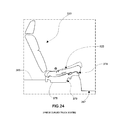
- FIG. 24 is a side view of an alternate seat assembly 320 mounted on the floor pan 367 of a vehicle.
- the base 370 is mounted to the raised portion 366 of the floor pan 367 .
- the base 370 has a concave shape and includes a track 376 extending through an arc.
- the lower cushion 322 is operably coupled to the track 376 for sliding along the track 376 relative to the base 370 . Because the track 376 has an arcuate shape, when the lower cushion 322 slides longitudinally forward, it also rocks upwardly relative to the base 370 .
- a braking mechanism 379 locks the lower cushion 322 to the base 370 , and a towel bar 381 moves between an engaged position for restricting movement of the lower cushion 322 relative to the base 370 and a disengaged position for allowing the lower cushion 322 to move along the track 376 .
- FIG. 25 is a side view of yet another seat assembly 420 mounted on the floor pan 467 of a vehicle.
- the base 470 has a generally obtuse triangular shape with a track in the form of a pivot point 476 at its apex.
- the lower cushion 422 engages the base 470 at the pivot point 476 , and the back of the lower cushion 422 is configured to rock relative to the base 470 about the pivot point 476 .
- the seat assembly 420 also includes a braking mechanism 479 for locking the lower cushion 422 to the base 470 including a towel bar 481 moveable between an up position for allowing the lower cushion 422 to rock relative to the base 470 and a down position for restricting movement of the lower cushion 422 relative to the base 470 . Additionally, the back of the lower cushion 422 is inclined to accommodate the rocking described above.
Landscapes
- Engineering & Computer Science (AREA)
- Aviation & Aerospace Engineering (AREA)
- Transportation (AREA)
- Mechanical Engineering (AREA)
- Seats For Vehicles (AREA)
Abstract
Description
Claims (17)
Priority Applications (1)
| Application Number | Priority Date | Filing Date | Title |
|---|---|---|---|
| US13/993,125 US9649957B2 (en) | 2010-12-17 | 2011-12-16 | Second row vehicle seat |
Applications Claiming Priority (3)
| Application Number | Priority Date | Filing Date | Title |
|---|---|---|---|
| US201061424226P | 2010-12-17 | 2010-12-17 | |
| US13/993,125 US9649957B2 (en) | 2010-12-17 | 2011-12-16 | Second row vehicle seat |
| PCT/US2011/065495 WO2012083167A1 (en) | 2010-12-17 | 2011-12-16 | Second row vehicle seat |
Publications (2)
| Publication Number | Publication Date |
|---|---|
| US20130257113A1 US20130257113A1 (en) | 2013-10-03 |
| US9649957B2 true US9649957B2 (en) | 2017-05-16 |
Family
ID=46245127
Family Applications (1)
| Application Number | Title | Priority Date | Filing Date |
|---|---|---|---|
| US13/993,125 Active 2032-01-06 US9649957B2 (en) | 2010-12-17 | 2011-12-16 | Second row vehicle seat |
Country Status (4)
| Country | Link |
|---|---|
| US (1) | US9649957B2 (en) |
| EP (1) | EP2651690B1 (en) |
| CN (1) | CN103402813B (en) |
| WO (1) | WO2012083167A1 (en) |
Cited By (1)
| Publication number | Priority date | Publication date | Assignee | Title |
|---|---|---|---|---|
| US10106060B2 (en) * | 2014-10-17 | 2018-10-23 | Ts Tech Co., Ltd. | Vehicle seat |
Families Citing this family (10)
| Publication number | Priority date | Publication date | Assignee | Title |
|---|---|---|---|---|
| US8899684B2 (en) * | 2010-07-01 | 2014-12-02 | Johnson Controls Techonology Company | Second row package |
| US9333885B2 (en) * | 2013-08-26 | 2016-05-10 | Ford Global Technologies, Llc | Folding vehicle seat |
| US9168850B2 (en) * | 2013-12-19 | 2015-10-27 | Ford Global Technologies, Llc | Utility seat assembly |
| CN109475265B (en) * | 2016-04-08 | 2023-06-02 | 伊莱克斯家用产品公司 | Folding tableware shelf |
| DE102016110404A1 (en) * | 2016-06-06 | 2017-12-07 | Grammer Ag | Vehicle seat with combined adjustment options |
| CN107298042B (en) * | 2017-07-21 | 2023-05-05 | 长春富维安道拓汽车饰件系统有限公司 | Cushion locking mechanism |
| CN109808717B (en) * | 2017-11-20 | 2021-05-04 | 中车唐山机车车辆有限公司 | Carriage and train |
| DE102018219964A1 (en) * | 2018-11-21 | 2020-05-28 | Brose Fahrzeugteile SE & Co. Kommanditgesellschaft, Coburg | Vehicle seat with swiveling seat shell part |
| FR3119349A1 (en) * | 2021-02-03 | 2022-08-05 | Psa Automobiles Sa | Reclining seat for motor vehicle |
| US12103443B2 (en) | 2022-01-10 | 2024-10-01 | Faurecia Automotive Seating, Llc | Vehicle and occupant support for a vehicle |
Citations (18)
| Publication number | Priority date | Publication date | Assignee | Title |
|---|---|---|---|---|
| US4781414A (en) * | 1986-11-05 | 1988-11-01 | Rockwell-Cim | Device for adjusting the height and the attitude of a seat structure, in particular for a vehicle |
| US5022707A (en) * | 1988-01-07 | 1991-06-11 | Life Force Associates, L.P. | Vehicle safety device |
| US5244252A (en) | 1990-10-29 | 1993-09-14 | Hector Serber | Seat assembly and method |
| US5437494A (en) * | 1992-10-29 | 1995-08-01 | Life Force Associates, L.P. | Rearward moving seat |
| US5449218A (en) * | 1988-01-07 | 1995-09-12 | Life Force, Inc. | Vehicle safety device |
| US5567006A (en) | 1993-10-01 | 1996-10-22 | Mccarthy; Joseph | Vehicle seat with articulated sections |
| US5967604A (en) * | 1996-12-17 | 1999-10-19 | Aisin Seiki Kabushiki Kaisha | Vehicle seat apparatus |
| US6086154A (en) | 1998-03-31 | 2000-07-11 | Dura Automotive Systems, Inc. | Infinitely adjustable seat track assembly |
| US6334648B1 (en) * | 1997-03-21 | 2002-01-01 | Girsberger Holding Ag | Vehicle seat |
| US6578917B1 (en) * | 1998-11-18 | 2003-06-17 | Girsberger Holding Ag | Seat |
| US6817645B2 (en) | 2002-03-14 | 2004-11-16 | Mazda Motor Corporation | Seat arrangement for a vehicle |
| US20050242634A1 (en) * | 2004-04-30 | 2005-11-03 | Hector Serber | Seat assembly with movable seat and backrest and method |
| WO2005102772A2 (en) | 2004-04-15 | 2005-11-03 | Renault S.A.S. | Motor vehicle rear seat comprising a retractable anti-submarining element, and corresponding vehicle |
| US20060055214A1 (en) * | 2004-04-30 | 2006-03-16 | Hector Serber | Seat assembly with movable seat and backrest and method |
| US7390060B2 (en) * | 2005-04-12 | 2008-06-24 | Stanzwerk Wetter Sichelschmidt Gmbh & Co. Kg | Reclining chair |
| US7918501B1 (en) * | 2007-07-18 | 2011-04-05 | Dennis Hawkins Hanson | Vehicle safety seat |
| US20120305734A1 (en) * | 2009-12-18 | 2012-12-06 | Johnson Controls Technology Company | Seat track system |
| US8556346B2 (en) * | 2010-11-01 | 2013-10-15 | Ford Global Technologies, Llc | Vehicle seat with rotating angle adjustment |
Family Cites Families (2)
| Publication number | Priority date | Publication date | Assignee | Title |
|---|---|---|---|---|
| US4674713A (en) * | 1984-09-28 | 1987-06-23 | Falcon Jet Corporation | Double airplane seats |
| CN2709237Y (en) * | 2004-07-14 | 2005-07-13 | 上海延锋江森座椅有限公司 | Regulatable seat |
-
2011
- 2011-12-16 CN CN201180060148.9A patent/CN103402813B/en active Active
- 2011-12-16 WO PCT/US2011/065495 patent/WO2012083167A1/en not_active Ceased
- 2011-12-16 EP EP11847970.8A patent/EP2651690B1/en active Active
- 2011-12-16 US US13/993,125 patent/US9649957B2/en active Active
Patent Citations (18)
| Publication number | Priority date | Publication date | Assignee | Title |
|---|---|---|---|---|
| US4781414A (en) * | 1986-11-05 | 1988-11-01 | Rockwell-Cim | Device for adjusting the height and the attitude of a seat structure, in particular for a vehicle |
| US5022707A (en) * | 1988-01-07 | 1991-06-11 | Life Force Associates, L.P. | Vehicle safety device |
| US5449218A (en) * | 1988-01-07 | 1995-09-12 | Life Force, Inc. | Vehicle safety device |
| US5244252A (en) | 1990-10-29 | 1993-09-14 | Hector Serber | Seat assembly and method |
| US5437494A (en) * | 1992-10-29 | 1995-08-01 | Life Force Associates, L.P. | Rearward moving seat |
| US5567006A (en) | 1993-10-01 | 1996-10-22 | Mccarthy; Joseph | Vehicle seat with articulated sections |
| US5967604A (en) * | 1996-12-17 | 1999-10-19 | Aisin Seiki Kabushiki Kaisha | Vehicle seat apparatus |
| US6334648B1 (en) * | 1997-03-21 | 2002-01-01 | Girsberger Holding Ag | Vehicle seat |
| US6086154A (en) | 1998-03-31 | 2000-07-11 | Dura Automotive Systems, Inc. | Infinitely adjustable seat track assembly |
| US6578917B1 (en) * | 1998-11-18 | 2003-06-17 | Girsberger Holding Ag | Seat |
| US6817645B2 (en) | 2002-03-14 | 2004-11-16 | Mazda Motor Corporation | Seat arrangement for a vehicle |
| WO2005102772A2 (en) | 2004-04-15 | 2005-11-03 | Renault S.A.S. | Motor vehicle rear seat comprising a retractable anti-submarining element, and corresponding vehicle |
| US20050242634A1 (en) * | 2004-04-30 | 2005-11-03 | Hector Serber | Seat assembly with movable seat and backrest and method |
| US20060055214A1 (en) * | 2004-04-30 | 2006-03-16 | Hector Serber | Seat assembly with movable seat and backrest and method |
| US7390060B2 (en) * | 2005-04-12 | 2008-06-24 | Stanzwerk Wetter Sichelschmidt Gmbh & Co. Kg | Reclining chair |
| US7918501B1 (en) * | 2007-07-18 | 2011-04-05 | Dennis Hawkins Hanson | Vehicle safety seat |
| US20120305734A1 (en) * | 2009-12-18 | 2012-12-06 | Johnson Controls Technology Company | Seat track system |
| US8556346B2 (en) * | 2010-11-01 | 2013-10-15 | Ford Global Technologies, Llc | Vehicle seat with rotating angle adjustment |
Cited By (2)
| Publication number | Priority date | Publication date | Assignee | Title |
|---|---|---|---|---|
| US10106060B2 (en) * | 2014-10-17 | 2018-10-23 | Ts Tech Co., Ltd. | Vehicle seat |
| US10414299B2 (en) | 2014-10-17 | 2019-09-17 | Ts Tech Co., Ltd. | Vehicle seat |
Also Published As
| Publication number | Publication date |
|---|---|
| CN103402813B (en) | 2017-11-21 |
| EP2651690B1 (en) | 2015-12-16 |
| EP2651690A1 (en) | 2013-10-23 |
| EP2651690A4 (en) | 2014-05-21 |
| CN103402813A (en) | 2013-11-20 |
| US20130257113A1 (en) | 2013-10-03 |
| WO2012083167A1 (en) | 2012-06-21 |
Similar Documents
| Publication | Publication Date | Title |
|---|---|---|
| US9649957B2 (en) | Second row vehicle seat | |
| US6578919B2 (en) | Vehicle seat | |
| US7568764B2 (en) | Reclining rear seat for vehicle having four-bar link | |
| CN108528284B (en) | Seat back lifting mechanism for a recumbent motor vehicle seat assembly | |
| CN103917406B (en) | Stowable seat arrangement for a motor vehicle | |
| EP2061674B1 (en) | Fold flat seat assembly with drive link | |
| EP2709492B1 (en) | Stadium and stowing seat | |
| US7255384B2 (en) | Vehicle seat that tips and kneels and folds into a stowage well | |
| US8256844B2 (en) | Vehicular seat having a walk in mechanism | |
| US9168848B2 (en) | Vehicle seating assembly | |
| US7478882B2 (en) | Motor vehicle seat | |
| US8770646B2 (en) | Adjustable floating seat | |
| GB2417197A (en) | Vehicle seat with folding and sliding action | |
| US9919626B2 (en) | Folding and reclining rear seat system | |
| GB2386550A (en) | Adjustable seat | |
| US7240949B1 (en) | Adjustable seat assembly | |
| EP2855196B1 (en) | Fold and kneel seat wtih rearward folding motion | |
| US11884185B2 (en) | Vehicle seat | |
| US9604553B2 (en) | Virtual H-point seat back system | |
| EP2587965B1 (en) | Second row package | |
| US8899684B2 (en) | Second row package | |
| US20240092232A1 (en) | Vehicle seat with a locking lever |
Legal Events
| Date | Code | Title | Description |
|---|---|---|---|
| AS | Assignment |
Owner name: JOHNSON CONTROLS TECHNOLOGY COMPANY, MICHIGAN Free format text: ASSIGNMENT OF ASSIGNORS INTEREST;ASSIGNORS:SEIBOLD, KURT A.;POTES, DUANE, JR.;GOMEZ, JOHN;AND OTHERS;REEL/FRAME:030595/0831 Effective date: 20130612 |
|
| FEPP | Fee payment procedure |
Free format text: PAYOR NUMBER ASSIGNED (ORIGINAL EVENT CODE: ASPN); ENTITY STATUS OF PATENT OWNER: LARGE ENTITY |
|
| STCF | Information on status: patent grant |
Free format text: PATENTED CASE |
|
| AS | Assignment |
Owner name: ADIENT LUXEMBOURG HOLDING S.A.R.L., LUXEMBOURG Free format text: ASSIGNMENT OF ASSIGNORS INTEREST;ASSIGNOR:JOHNSON CONTROLS TECHNOLOGY COMPANY;REEL/FRAME:044531/0375 Effective date: 20171003 |
|
| MAFP | Maintenance fee payment |
Free format text: PAYMENT OF MAINTENANCE FEE, 4TH YEAR, LARGE ENTITY (ORIGINAL EVENT CODE: M1551); ENTITY STATUS OF PATENT OWNER: LARGE ENTITY Year of fee payment: 4 |
|
| AS | Assignment |
Owner name: ADIENT GLOBAL HOLDINGS LTD., JERSEY Free format text: ASSIGNMENT OF ASSIGNORS INTEREST;ASSIGNOR:ADIENT LUXEMBOURG HOLDING S.A.R.L.;REEL/FRAME:058751/0678 Effective date: 20220110 Owner name: ADIENT GLOBAL HOLDINGS LTD., JERSEY Free format text: ASSIGNMENT OF ASSIGNOR'S INTEREST;ASSIGNOR:ADIENT LUXEMBOURG HOLDING S.A.R.L.;REEL/FRAME:058751/0678 Effective date: 20220110 |
|
| AS | Assignment |
Owner name: ADIENT US LLC, MICHIGAN Free format text: ASSIGNMENT OF ASSIGNORS INTEREST;ASSIGNOR:ADIENT GLOBAL HOLDINGS LTD.;REEL/FRAME:059086/0636 Effective date: 20220127 Owner name: ADIENT US LLC, MICHIGAN Free format text: ASSIGNMENT OF ASSIGNOR'S INTEREST;ASSIGNOR:ADIENT GLOBAL HOLDINGS LTD.;REEL/FRAME:059086/0636 Effective date: 20220127 |
|
| AS | Assignment |
Owner name: JPMORGAN CHASE BANK, N.A., AS COLLATERAL AGENT, NEW YORK Free format text: NOTICE OF GRANT OF SECURITY INTEREST IN IP;ASSIGNOR:ADIENT US LLC;REEL/FRAME:061956/0301 Effective date: 20221116 |
|
| AS | Assignment |
Owner name: U.S. BANK TRUST COMPANY, NATIONAL ASSOCIATION, AS COLLATERAL AGENT, WISCONSIN Free format text: NOTICE OF GRANT OF SECURITY INTEREST;ASSIGNORS:CNI ENTERPRISES, INC.;ADIENT US LLC;REEL/FRAME:063085/0391 Effective date: 20230314 |
|
| MAFP | Maintenance fee payment |
Free format text: PAYMENT OF MAINTENANCE FEE, 8TH YEAR, LARGE ENTITY (ORIGINAL EVENT CODE: M1552); ENTITY STATUS OF PATENT OWNER: LARGE ENTITY Year of fee payment: 8 |