US9634395B2 - Monopole antenna with a tapered Balun - Google Patents
Monopole antenna with a tapered Balun Download PDFInfo
- Publication number
- US9634395B2 US9634395B2 US13/871,057 US201313871057A US9634395B2 US 9634395 B2 US9634395 B2 US 9634395B2 US 201313871057 A US201313871057 A US 201313871057A US 9634395 B2 US9634395 B2 US 9634395B2
- Authority
- US
- United States
- Prior art keywords
- arms
- antenna
- monopole antenna
- microstrip
- plane
- Prior art date
- Legal status (The legal status is an assumption and is not a legal conclusion. Google has not performed a legal analysis and makes no representation as to the accuracy of the status listed.)
- Active, expires
Links
- 230000005404 monopole Effects 0.000 title claims abstract description 68
- 230000005855 radiation Effects 0.000 claims description 22
- 238000000034 method Methods 0.000 claims description 20
- 230000008878 coupling Effects 0.000 claims description 3
- 238000010168 coupling process Methods 0.000 claims description 3
- 238000005859 coupling reaction Methods 0.000 claims description 3
- 238000004891 communication Methods 0.000 description 32
- 238000012545 processing Methods 0.000 description 25
- 230000006870 function Effects 0.000 description 17
- 238000005516 engineering process Methods 0.000 description 9
- 230000015654 memory Effects 0.000 description 9
- 238000009826 distribution Methods 0.000 description 7
- 230000001413 cellular effect Effects 0.000 description 6
- 238000003860 storage Methods 0.000 description 6
- 230000001131 transforming effect Effects 0.000 description 6
- 230000005540 biological transmission Effects 0.000 description 4
- 238000004590 computer program Methods 0.000 description 4
- 125000004122 cyclic group Chemical group 0.000 description 4
- 238000013461 design Methods 0.000 description 4
- 238000010586 diagram Methods 0.000 description 4
- 230000008901 benefit Effects 0.000 description 3
- 230000010365 information processing Effects 0.000 description 3
- 230000007246 mechanism Effects 0.000 description 3
- 230000004048 modification Effects 0.000 description 3
- 238000012986 modification Methods 0.000 description 3
- 230000008569 process Effects 0.000 description 3
- 230000007480 spreading Effects 0.000 description 3
- 238000003892 spreading Methods 0.000 description 3
- 238000006243 chemical reaction Methods 0.000 description 2
- 238000013500 data storage Methods 0.000 description 2
- 230000000994 depressogenic effect Effects 0.000 description 2
- 238000012905 input function Methods 0.000 description 2
- 239000004973 liquid crystal related substance Substances 0.000 description 2
- 238000007726 management method Methods 0.000 description 2
- 238000004519 manufacturing process Methods 0.000 description 2
- 230000003287 optical effect Effects 0.000 description 2
- 230000002093 peripheral effect Effects 0.000 description 2
- 230000004044 response Effects 0.000 description 2
- 101100490659 Arabidopsis thaliana AGP17 gene Proteins 0.000 description 1
- 241000699670 Mus sp. Species 0.000 description 1
- 101100049938 Neurospora crassa (strain ATCC 24698 / 74-OR23-1A / CBS 708.71 / DSM 1257 / FGSC 987) exr-1 gene Proteins 0.000 description 1
- 230000009471 action Effects 0.000 description 1
- 230000004075 alteration Effects 0.000 description 1
- 238000003491 array Methods 0.000 description 1
- 230000009286 beneficial effect Effects 0.000 description 1
- 238000004422 calculation algorithm Methods 0.000 description 1
- 230000010267 cellular communication Effects 0.000 description 1
- 238000013479 data entry Methods 0.000 description 1
- 238000011161 development Methods 0.000 description 1
- 230000000694 effects Effects 0.000 description 1
- 239000000835 fiber Substances 0.000 description 1
- 230000010354 integration Effects 0.000 description 1
- 230000003993 interaction Effects 0.000 description 1
- 230000007774 longterm Effects 0.000 description 1
- 239000000463 material Substances 0.000 description 1
- 238000010295 mobile communication Methods 0.000 description 1
- 238000004806 packaging method and process Methods 0.000 description 1
- 101150101384 rat1 gene Proteins 0.000 description 1
- 238000013515 script Methods 0.000 description 1
- 230000008054 signal transmission Effects 0.000 description 1
- 239000007787 solid Substances 0.000 description 1
- 238000001228 spectrum Methods 0.000 description 1
- 239000000126 substance Substances 0.000 description 1
- 238000006467 substitution reaction Methods 0.000 description 1
- 239000000758 substrate Substances 0.000 description 1
- 230000001960 triggered effect Effects 0.000 description 1
Images


Classifications
-
- H—ELECTRICITY
- H01—ELECTRIC ELEMENTS
- H01Q—ANTENNAS, i.e. RADIO AERIALS
- H01Q9/00—Electrically-short antennas having dimensions not more than twice the operating wavelength and consisting of conductive active radiating elements
- H01Q9/04—Resonant antennas
- H01Q9/30—Resonant antennas with feed to end of elongated active element, e.g. unipole
- H01Q9/40—Element having extended radiating surface
-
- H—ELECTRICITY
- H01—ELECTRIC ELEMENTS
- H01Q—ANTENNAS, i.e. RADIO AERIALS
- H01Q1/00—Details of, or arrangements associated with, antennas
- H01Q1/48—Earthing means; Earth screens; Counterpoises
-
- H—ELECTRICITY
- H01—ELECTRIC ELEMENTS
- H01Q—ANTENNAS, i.e. RADIO AERIALS
- H01Q1/00—Details of, or arrangements associated with, antennas
- H01Q1/36—Structural form of radiating elements, e.g. cone, spiral, umbrella; Particular materials used therewith
- H01Q1/38—Structural form of radiating elements, e.g. cone, spiral, umbrella; Particular materials used therewith formed by a conductive layer on an insulating support
-
- Y—GENERAL TAGGING OF NEW TECHNOLOGICAL DEVELOPMENTS; GENERAL TAGGING OF CROSS-SECTIONAL TECHNOLOGIES SPANNING OVER SEVERAL SECTIONS OF THE IPC; TECHNICAL SUBJECTS COVERED BY FORMER USPC CROSS-REFERENCE ART COLLECTIONS [XRACs] AND DIGESTS
- Y10—TECHNICAL SUBJECTS COVERED BY FORMER USPC
- Y10T—TECHNICAL SUBJECTS COVERED BY FORMER US CLASSIFICATION
- Y10T29/00—Metal working
- Y10T29/49—Method of mechanical manufacture
- Y10T29/49002—Electrical device making
- Y10T29/49016—Antenna or wave energy "plumbing" making
Definitions
- 60 GHz communication may facilitate a large communication bandwidth and higher data rates relative to lower frequencies of operation (e.g., WiFi).
- the shorter wavelength in 60 GHz based systems allows for small antenna dimensions that enable multiple antenna systems, such as phased arrays.
- the 60 GHz antenna form factor is on the order of millimeters, which requires advanced integration techniques for packaging. Routing signals from a chipset source to an antenna is also problematic. There may also be competing requirements between the antenna and the support circuitry. For example, the antenna may need a substrate with low permittivity and high relative thickness to obtain the greatest efficiency, a wide bandwidth, an undisturbed radiation pattern, and less coupling to other components. Conversely, the radio frequency (RF) components may require thin materials with high permittivity for compactness, better signal transmission, and better thermal dissipation.
- RF radio frequency
- antennas there are various types of antennas. In a 60 GHz based system, it may be beneficial to have antennas that are omnidirectional.
- a typical example is a printed planar monopole antenna fed with a microstrip transmission line.
- the microstrip line length could be on the order of a wavelength. Then, if the transmission line is unbalanced, strong radiation may come from the transmission line itself.
- a monopole antenna may suffer from a strong current balancing problem.
- a balanced feed (Balun) needs to be designed to ensure that the distribution of current in the ground and the microstrip transmission line do not cause radiation problems.
- FIG. 1 depicts an exemplary system in which the present disclosure may be implemented
- FIG. 2 shows a wireless-enabled communications environment including an embodiment of a client node
- FIG. 3 is a simplified block diagram of an exemplary client node comprising a digital signal processor (DSP);
- DSP digital signal processor
- FIG. 4A illustrates a monopole antenna fed by a microstrip line
- FIG. 4B illustrates a S11 reflection coefficient for the monopole antenna of FIG. 4A ;
- FIG. 4C illustrates a three-dimensional (3D) radiation pattern for the monopole antenna of FIG. 4A ;
- FIG. 4D illustrates the current distribution for the monopole antenna of FIG. 4A ;
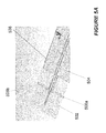
- FIG. 5A illustrates a monopole antenna with two straight arms formed in the ground under it
- FIG. 5B illustrates a S11 reflection coefficient for the monopole antenna of FIG. 5A ;
- FIG. 5C illustrates a 3D radiation pattern for the monopole antenna of FIG. 5A ;
- FIG. 5D illustrates the current distribution for the monopole antenna of FIG. 5A ;
- FIG. 6A illustrates a monopole antenna with two curved arms formed in the ground under it
- FIG. 6B illustrates a S11 reflection coefficient for the monopole antenna of FIG. 6A ;
- FIG. 6C illustrates a 3D radiation pattern for the monopole antenna of FIG. 6A ;
- FIG. 6D illustrates the current distribution for the monopole antenna of FIG. 6A ;
- FIG. 7A illustrates a monopole antenna with a stepwise tapered microstrip feed
- FIG. 7B illustrates a S11 reflection coefficient for the monopole antenna of FIG. 7A ;
- FIG. 7C illustrates a 3D radiation pattern for the monopole antenna of FIG. 7A ;
- FIG. 7D illustrates the current distribution for the monopole antenna of FIG. 7A ;
- FIG. 8A illustrates a monopole antenna with a stepwise tapered microstrip feed and curved arms in the ground underneath it;
- FIG. 8B illustrates a S11 reflection coefficient for the monopole antenna of FIG. 8A ;
- FIG. 8C illustrates a 3D radiation pattern for the monopole antenna of FIG. 8A ;
- FIG. 8D illustrates the current distribution for the monopole antenna of FIG. 8A .
- FIG. 9 illustrates a flow chart of an exemplary method.
- the present disclosure is directed in general to communications systems and methods for operating the same.
- Embodiments are directed to a balun structure comprising: a monopole antenna, and a microstrip coupled to the monopole antenna and comprising a ground plane modified to include at least two arms.
- Embodiments are directed to a balun structure comprising: a monopole antenna, and a microstrip coupled to the monopole antenna using a stepwise tapered microstrip feed.
- Embodiments are directed to a method comprising: modifying a ground plane of a microstrip to include at least two arms, and coupling the microstrip to a monopole antenna.
- a component may be, but is not limited to being, a processor, a process running on a processor, an object, an executable instruction sequence, a thread of execution, a program, or a computer.
- a component may be, but is not limited to being, a processor, a process running on a processor, an object, an executable instruction sequence, a thread of execution, a program, or a computer.
- an application running on a computer and the computer itself can be a component.
- One or more components may reside within a process or thread of execution and a component may be localized on one computer or distributed between two or more computers.
- node broadly refers to a connection point, such as a redistribution point or a communication endpoint, of a communication environment, such as a network. Accordingly, such nodes refer to an active electronic device capable of sending, receiving, or forwarding information over a communications channel. Examples of such nodes include data circuit-terminating equipment (DCE), such as a modem, hub, bridge or switch, and data terminal equipment (DTE), such as a handset, a printer or a host computer (e.g., a router, workstation or server).
- DCE data circuit-terminating equipment
- DTE data terminal equipment
- Examples of local area network (LAN) or wide area network (WAN) nodes include computers, packet switches, cable modems, Data Subscriber Line (DSL) modems, and wireless LAN (WLAN) access points.
- Examples of Internet or Intranet nodes include host computers identified by an Internet Protocol (IP) address, bridges and WLAN access points.
- examples of nodes in cellular communication include base stations, relays, base station controllers, radio network controllers, home location registers (HLR), visited location registers (VLR), Gateway GPRS Support Nodes (GGSN), Serving GPRS Support Nodes (SGSN), Serving Gateways (S-GW), and Packet Data Network Gateways (PDN-GW).
- HLR home location registers
- VLR Visit location registers
- GGSN Gateway GPRS Support Nodes
- SGSN Serving GPRS Support Nodes
- S-GW Serving Gateways
- PDN-GW Packet Data Network Gateways
- nodes include client nodes, server nodes, peer nodes and access nodes.
- a client node may refer to wireless devices such as mobile telephones, smart phones, personal digital assistants (PDAs), handheld devices, portable computers, tablet computers, and similar devices or other user equipment (UE) that has telecommunications capabilities.
- PDAs personal digital assistants
- client nodes may likewise refer to a mobile, wireless device, or alternatively, to devices that have similar capabilities that are not generally transportable, such as desktop computers, set-top boxes, or sensors.
- a network node as used herein, generally includes all nodes with the exception of client nodes, server nodes and access nodes.
- a server node refers to an information processing device (e.g., a host computer), or series of information processing devices, that perform information processing requests submitted by other nodes.
- a peer node may sometimes serve as client node, and at other times, a server node.
- a node that actively routes data for other networked devices as well as itself may be referred to as a supernode.
- An access node refers to a node that provides a client node access to a communication environment.
- Examples of access nodes include cellular network base stations and wireless broadband (e.g., WiFi, WiMAX, etc.) access points, which provide corresponding cell and WLAN coverage areas. WiGig® and its equivalents in the greater than 50 GHz range are also examples of wireless broadband.
- a macrocell is used to generally describe a traditional cellular network cell coverage area. Such macrocells are typically found in rural areas, along highways, or in less populated areas.
- a microcell refers to a cellular network cell with a smaller coverage area than that of a macrocell. Such micro cells are typically used in a densely populated urban area.
- a picocell refers to a cellular network coverage area that is less than that of a microcell.
- An example of the coverage area of a picocell may be a large office, a shopping mall, or a train station.
- a femtocell as used herein, currently refers to the smallest commonly accepted area of cellular network coverage. As an example, the coverage area of a femtocell is sufficient for homes or small offices.
- a coverage area of less than two kilometers typically corresponds to a microcell, 200 meters or less for a picocell, and on the order of 10 meters for a femtocell.
- the actual dimensions of the cell may depend on the radio frequency of operation, the radio propagation conditions and the density of communications traffic.
- a client node communicating with an access node associated with a macrocell is referred to as a “macrocell client.”
- a client node communicating with an access node associated with a microcell, picocell, or femtocell is respectively referred to as a “microcell client,” “picocell client,” or “femtocell client.”
- computer readable media can include but are not limited to magnetic storage devices (e.g., hard disk, floppy disk, magnetic strips, etc.), optical disks such as a compact disk (CD) or digital versatile disk (DVD), smart cards, and flash memory devices (e.g., card, stick, etc.).
- magnetic storage devices e.g., hard disk, floppy disk, magnetic strips, etc.
- optical disks such as a compact disk (CD) or digital versatile disk (DVD)
- smart cards e.g., card, stick, etc.
- exemplary is used herein to mean serving as an example, instance, or illustration. Any aspect or design described herein as “exemplary” is not necessarily to be construed as preferred or advantageous over other aspects or designs. Those of skill in the art will recognize many modifications may be made to this configuration without departing from the scope, spirit or intent of the claimed subject matter. Furthermore, the disclosed subject matter may be implemented as a system, method, apparatus, or article of manufacture using standard programming and engineering techniques to produce software, firmware, hardware, or any combination thereof to control a computer or processor-based device to implement aspects detailed herein.
- FIG. 1 illustrates an example of a system 100 suitable for implementing one or more embodiments disclosed herein.
- the system 100 comprises a processor 110 , which may be referred to as a central processor unit (CPU) or digital signal processor (DSP), network connectivity interfaces 120 , random access memory (RAM) 130 , read only memory (ROM) 140 , secondary storage 150 , and input/output (I/O) devices 160 .
- processor 110 which may be referred to as a central processor unit (CPU) or digital signal processor (DSP), network connectivity interfaces 120 , random access memory (RAM) 130 , read only memory (ROM) 140 , secondary storage 150 , and input/output (I/O) devices 160 .
- RAM random access memory
- ROM read only memory
- secondary storage 150 secondary storage
- I/O input/output
- I/O input/output
- some of these components may not be present or may be combined in various combinations with one another or with other components not shown. These components may be located in a single physical entity or
- the processor 110 executes instructions, codes, computer programs, or scripts that it might access from the network connectivity interfaces 120 , RAM 130 , or ROM 140 . While only one processor 110 is shown, multiple processors may be present. Thus, while instructions may be discussed as being executed by a processor 110 , the instructions may be executed simultaneously, serially, or otherwise by one or multiple processors 110 implemented as one or more CPU chips.
- the network connectivity interfaces 120 may take the form of modems, modem banks, Ethernet devices, universal serial bus (USB) interface devices, serial interfaces, token ring devices, fiber distributed data interface (FDDI) devices, wireless local area network (WLAN) devices (including radio, optical or infra-red signals), radio transceiver devices such as code division multiple access (CDMA) devices, global system for mobile communications (GSM) radio transceiver devices, long term evolution (LTE) radio transceiver devices, worldwide interoperability for microwave access (WiMAX) devices, and/or other well-known interfaces for connecting to networks, including Personal Area Networks (PANs) such as Bluetooth.
- These network connectivity interfaces 120 may enable the processor 110 to communicate with the Internet or one or more telecommunications networks or other networks from which the processor 110 might receive information or to which the processor 110 might output information.
- the network connectivity interfaces 120 may also be capable of transmitting or receiving data wirelessly in the form of electromagnetic waves, such as radio frequency signals or microwave frequency signals.
- Information transmitted or received by the network connectivity interfaces 120 may include data that has been processed by the processor 110 or instructions that are to be executed by processor 110 .
- the data may be ordered according to different sequences as may be desirable for either processing or generating the data or transmitting or receiving the data.
- the RAM 130 may be used to store volatile data and instructions that are executed by the processor 110 .
- the ROM 140 shown in FIG. 1 may likewise be used to store instructions and data that is read during execution of the instructions.
- the secondary storage 150 is typically comprised of one or more disk drives, solid state drives, or tape drives and may be used for non-volatile storage of data or as an overflow data storage device if RAM 130 is not large enough to hold all working data. Secondary storage 150 may likewise be used to store programs that are loaded into RAM 130 when such programs are selected for execution.
- the I/O devices 160 may include liquid crystal displays (LCDs), Light Emitting Diode (LED) displays, Organic Light Emitting Diode (OLED) displays, projectors, televisions, touch screen displays, keyboards, keypads, switches, dials, mice, track balls, track pads, voice recognizers, card readers, paper tape readers, printers, video monitors, or other well-known input/output devices.
- LCDs liquid crystal displays
- LED Light Emitting Diode
- OLED Organic Light Emitting Diode
- projectors televisions, touch screen displays, keyboards, keypads, switches, dials, mice, track balls, track pads, voice recognizers, card readers, paper tape readers, printers, video monitors, or other well-known input/output devices.
- FIG. 2 shows a wireless-enabled communications environment including an embodiment of a client node as implemented in an embodiment of the disclosure.
- the client node 202 may take various forms including a wireless handset, a pager, a smart phone, or a personal digital assistant (PDA).
- the client node 202 may also comprise a portable computer, a tablet computer, a laptop computer, or any computing device operable to perform data communication operations. Many suitable devices combine some or all of these functions.
- the client node 202 is not a general purpose computing device like a portable, laptop, or tablet computer, but rather is a special-purpose communications device such as a telecommunications device installed in a vehicle.
- the client node 202 may likewise be a device, include a device, or be included in a device that has similar capabilities but that is not transportable, such as a desktop computer, a set-top box, or a network node. In these and other embodiments, the client node 202 may support specialized activities such as gaming, inventory control, job control, task management functions, and so forth.
- the client node 202 includes a display 204 .
- the client node 202 may likewise include a touch-sensitive surface, a keyboard or other input keys 206 generally used for input by a user.
- the input keys 206 may likewise be a full or reduced alphanumeric keyboard such as QWERTY, DVORAK, AZERTY, and sequential keyboard types, or a traditional numeric keypad with alphabet letters associated with a telephone keypad.
- the input keys 206 may likewise include a trackwheel, an exit or escape key, a trackball, trackpad, touch sensitive input device and other navigational or functional keys, which may be moved to different positions, e.g., inwardly depressed, to provide further input function.
- the client node 202 may likewise present options for the user to select, controls for the user to actuate, and cursors or other indicators for the user to direct.
- the client node 202 may further accept data entry from the user, including numbers to dial or various parameter values for configuring the operation of the client node 202 .
- the client node 202 may further execute one or more software or firmware applications in response to user commands. These applications may configure the client node 202 to perform various customized functions in response to user interaction.
- the client node 202 may be programmed or configured over-the-air (OTA), for example from a wireless network access node ‘A’ 210 through ‘n’ 216 (e.g., a base station), a server node 224 (e.g., a host computer), or a peer client node 202 .
- OTA over-the-air
- a web browser which enables the display 204 to display a web page.
- the web page may be obtained from a server node 224 through a wireless connection with a wireless network 220 .
- a wireless network 220 broadly refers to any network using at least one wireless connection between two of its nodes.
- the various applications may likewise be obtained from a peer client node 202 or other system over a connection to the wireless network 220 or any other wirelessly-enabled communication network or system.
- the wireless network 220 comprises a plurality of wireless sub-networks (e.g., cells with corresponding coverage areas) ‘A’ 212 through ‘n’ 218 .
- the wireless sub-networks ‘A’ 212 through ‘n’ 218 may variously comprise a mobile wireless access network or a fixed wireless access network.
- the client node 202 transmits and receives communication signals, which are respectively communicated to and from the wireless network nodes ‘A’ 210 through ‘n’ 216 by wireless network antennas ‘A’ 208 through ‘n’ 214 (e.g., cell towers).
- the communication signals are used by the wireless network access nodes ‘A’ 210 through ‘n’ 216 to establish a wireless communication session with the client node 202 .
- the network access nodes ‘A’ 210 through ‘n’ 216 broadly refer to any access node of a wireless network.
- the wireless network access nodes ‘A’ 210 through ‘n’ 216 are respectively coupled to wireless sub-networks ‘A’ 212 through ‘n’ 218 , which are in turn connected to the wireless network 220 .
- the wireless network 220 is coupled to a core network 222 , e.g., a global computer network such as the Internet.
- a core network 222 e.g., a global computer network such as the Internet.
- the client node 202 has access to information on various hosts, such as the server node 224 .
- the server node 224 may provide content that may be shown on the display 204 or used by the client node processor 110 for its operations.
- the client node 202 may access the wireless network 220 through a peer client node 202 acting as an intermediary, in a relay type or hop type of connection.
- the client node 202 may be tethered and obtain its data from a linked device that is connected to the wireless sub-network 212 .
- Skilled practitioners of the art will recognize that many such embodiments are possible and the foregoing is not intended to limit the spirit, scope, or intention of the disclosure.
- FIG. 3 depicts a block diagram of an exemplary client node as implemented with a digital signal processor (DSP) in accordance with an embodiment of the disclosure. While various components of a client node 202 are depicted, various embodiments of the client node 202 may include a subset of the listed components or additional components not listed. As shown in FIG. 3 , the client node 202 includes a DSP 302 and a memory 304 .
- DSP digital signal processor
- the client node 202 may further include an antenna and front end unit 306 , a radio frequency (RF) transceiver 308 , an analog baseband processing unit 310 , a microphone 312 , an earpiece speaker 314 , a headset port 316 , a bus 318 , such as a system bus or an input/output (I/O) interface bus, a removable memory card 320 , a universal serial bus (USB) port 322 , a short range wireless communication sub-system 324 , an alert 326 , a keypad 328 , a liquid crystal display (LCD) 330 , which may include a touch sensitive surface, an LCD controller 332 , a charge-coupled device (CCD) camera 334 , a camera controller 336 , and a global positioning system (GPS) sensor 338 , and a power management module 340 operably coupled to a power storage unit, such as a battery 342 .
- the client node 202 may further include an antenna and
- the DSP 302 or some other form of controller or central processing unit (CPU) operates to control the various components of the client node 202 in accordance with embedded software or firmware stored in memory 304 or stored in memory contained within the DSP 302 itself.
- the DSP 302 may execute other applications stored in the memory 304 or made available via information media such as portable data storage media like the removable memory card 320 or via wired or wireless network communications.
- the application software may comprise a compiled set of machine-readable instructions that configure the DSP 302 to provide the desired functionality, or the application software may be high-level software instructions to be processed by an interpreter or compiler to indirectly configure the DSP 302 .
- the antenna and front end unit 306 may be provided to convert between wireless signals and electrical signals, enabling the client node 202 to send and receive information from a cellular network or some other available wireless communications network or from a peer client node 202 .
- the antenna and front end unit 106 may include multiple antennas to support beam forming and/or multiple input multiple output (MIMO) operations.
- MIMO operations may provide spatial diversity, which can be used to overcome difficult channel conditions or to increase channel throughput.
- the antenna and front-end unit 306 may include antenna tuning or impedance matching components, RF power amplifiers, or low noise amplifiers.
- the RF transceiver 308 provides frequency shifting, converting received RF signals to baseband and converting baseband transmit signals to RF.
- a radio transceiver or RF transceiver may be understood to include other signal processing functionality such as modulation/demodulation, coding/decoding, interleaving/deinterleaving, spreading/despreading, inverse fast Fourier transforming (IFFT)/fast Fourier transforming (FFT), cyclic prefix appending/removal, and other signal processing functions.
- IFFT inverse fast Fourier transforming
- FFT fast Fourier transforming
- cyclic prefix appending/removal and other signal processing functions.
- the description here separates the description of this signal processing from the RF and/or radio stage and conceptually allocates that signal processing to the analog baseband processing unit 310 or the DSP 302 or other central processing unit.
- the radio access technology (RAT) RAT1 and RAT2 transceivers 354 , 358 , the IXRF 356 , the IRSL 352 and Multi-RAT subsystem 350 are operably coupled to the RF transceiver 308 and analog baseband processing unit 310 and then also coupled to the antenna and front end 306 via the RF transceiver 308 .
- RAT radio access technology
- the IXRF 356 the IXRF 356
- the IRSL 352 and Multi-RAT subsystem 350 are operably coupled to the RF transceiver 308 and analog baseband processing unit 310 and then also coupled to the antenna and front end 306 via the RF transceiver 308 .
- there may be multiple RAT transceivers there will typically be multiple antennas or front ends 306 or RF transceivers 308 , one for each RAT or band of operation.
- the analog baseband processing unit 310 may provide various analog processing of inputs and outputs for the RF transceivers 308 and the speech interfaces ( 312 , 314 , 316 ).
- the analog baseband processing unit 310 receives inputs from the microphone 312 and the headset 316 and provides outputs to the earpiece 314 and the headset 316 .
- the analog baseband processing unit 310 may have ports for connecting to the built-in microphone 312 and the earpiece speaker 314 that enable the client node 202 to be used as a cell phone.
- the analog baseband processing unit 310 may further include a port for connecting to a headset or other hands-free microphone and speaker configuration.
- the analog baseband processing unit 310 may provide digital-to-analog conversion in one signal direction and analog-to-digital conversion in the opposing signal direction. In various embodiments, at least some of the functionality of the analog baseband processing unit 310 may be provided by digital processing components, for example by the DSP 302 or by other central processing units.
- the DSP 302 may perform modulation/demodulation, coding/decoding, interleaving/deinterleaving, spreading/despreading, inverse fast Fourier transforming (IFFT)/fast Fourier transforming (FFT), cyclic prefix appending/removal, and other signal processing functions associated with wireless communications.
- IFFT inverse fast Fourier transforming
- FFT fast Fourier transforming
- cyclic prefix appending/removal and other signal processing functions associated with wireless communications.
- CDMA code division multiple access
- the DSP 302 may perform modulation, coding, interleaving, inverse fast Fourier transforming, and cyclic prefix appending, and for a receiver function the DSP 302 may perform cyclic prefix removal, fast Fourier transforming, deinterleaving, decoding, and demodulation.
- OFDMA orthogonal frequency division multiplex access
- the DSP 302 may communicate with a wireless network via the analog baseband processing unit 310 .
- the communication may provide Internet connectivity, enabling a user to gain access to content on the Internet and to send and receive e-mail or text messages.
- the input/output interface 318 interconnects the DSP 302 and various memories and interfaces.
- the memory 304 and the removable memory card 320 may provide software and data to configure the operation of the DSP 302 .
- the interfaces may be the USB interface 322 and the short range wireless communication sub-system 324 .
- the USB interface 322 may be used to charge the client node 202 and may also enable the client node 202 to function as a peripheral device to exchange information with a personal computer or other computer system.
- the short range wireless communication sub-system 324 may include an infrared port, a Bluetooth interface, an IEEE 802.11 compliant wireless interface, or any other short range wireless communication sub-system, which may enable the client node 202 to communicate wirelessly with other nearby client nodes and access nodes.
- the short-range wireless communication Sub-system 324 may also include suitable RF Transceiver, Antenna and Front End subsystems.
- the input/output interface (“Bus”) 318 may further connect the DSP 302 to the alert 326 that, when triggered, causes the client node 202 to provide a notice to the user, for example, by ringing, playing a melody, or vibrating.
- the alert 326 may serve as a mechanism for alerting the user to any of various events such as an incoming call, a new text message, and an appointment reminder by silently vibrating, or by playing a specific pre-assigned melody for a particular caller.
- the keypad 328 couples to the DSP 302 via the I/O interface (“Bus”) 318 to provide one mechanism for the user to make selections, enter information, and otherwise provide input to the client node 202 .
- the keyboard 328 may be a full or reduced alphanumeric keyboard such as QWERTY, DVORAK, AZERTY and sequential types, or a traditional numeric keypad with alphabet letters associated with a telephone keypad.
- the input keys may likewise include a trackwheel, track pad, an exit or escape key, a trackball, and other navigational or functional keys, which may be inwardly depressed to provide further input function.
- Another input mechanism may be the LCD 330 , which may include touch screen capability and also display text and/or graphics to the user.
- the LCD controller 332 couples the DSP 302 to the LCD 330 .
- the CCD camera 334 if equipped, enables the client node 202 to make digital pictures.
- the DSP 302 communicates with the CCD camera 334 via the camera controller 336 .
- a camera operating according to a technology other than Charge Coupled Device cameras may be employed.
- the GPS sensor 338 is coupled to the DSP 302 to decode global positioning system signals or other navigational signals, thereby enabling the client node 202 to determine its position.
- the GPS sensor 338 may be coupled to an antenna and front end (not shown) suitable for its band of operation.
- Various other peripherals may also be included to provide additional functions, such as radio and television reception.
- the client node (e.g., 202 ) comprises a first Radio Access Technology (RAT) transceiver 354 and a second RAT transceiver 358 .
- RAT Radio Access Technology
- the RAT transceivers ‘1’ 354 and ‘2’ 358 are in turn coupled to a multi-RAT communications subsystem 350 by an Inter-RAT Supervisory Layer Module 352 .
- the multi-RAT communications subsystem 350 is operably coupled to the Bus 318 .
- the respective radio protocol layers of the first Radio Access Technology (RAT) transceiver 354 and the second RAT transceiver 358 are operably coupled to one another through an Inter-RAT eXchange Function (IRXF) Module 356 .
- IXF Inter-RAT eXchange Function
- the network node acting as a server comprises a first communication link corresponding to data to/from the first RAT and a second communication link corresponding to data to/from the second RAT.
- Embodiments of the disclosure may also include a housing in which the components of FIG. 3 are secured.
- the antenna which can be part of the antenna and front end 306 , is positioned in the housing.
- the antenna might not be readily visible or distinguishable from the housing.
- One or more slots may be available in the housing to support the antenna.
- the antenna can be mostly positioned in the side of the housing.
- the antenna can be at least partially positioned in a trackpad, display, or touchscreen of a device (e.g., a mobile device).
- Embodiments of the disclosure may be operative at one or more frequencies.
- communication may occur at 60 GHz (which may be divided into one or more channels or bands, such as a first channel between 57.24 GHz and 59.4 GHz, a second channel between 59.4 GHz and 61.56 GHz, a third channel between 61.56 GHz and 63.72 GHz, and a fourth channel between 63.72 GHz and 65.88 GHz).
- an antenna may achieve communication in a range of 60 GHZ, +/ ⁇ 5 GHz or +/ ⁇ 6 GHz.
- Embodiments of the disclosure are directed to one or more systems, apparatuses, devices, and methods for making and using a Balun structure for a 60 GHz monopole antenna.
- a stepwise tapered feed may be used to improve matching.
- a monopole antenna may demonstrate enhanced balancing relative to conventional designs while retaining an omnidirectional radiation pattern.
- a monopole antenna 402 is shown as being fed by a microstrip line 404 .
- the operation of the antenna 402 /microstrip line 404 may take place at one or more frequencies, such as at 60 GHz
- the monopole 402 may have a bandwidth of approximately 13 GHz and a good match around 60 GHz.
- the radiation pattern shown in FIG. 4C may be “backward”, which may be due to currents flowing along the ground 438 and the microstrip 404 not being well-balanced with the monopole current ( FIG. 4D ).
- the total current flowing on the ground 438 and microstrip line 404 may contribute more to the radiation pattern than the monopole 402 .
- a monopole antenna 502 is shown as being fed by a microstrip line 504 .
- the operation of the antenna 502 /microstrip line 504 may be similar to the operation of the antenna 402 /microstrip line 404 .
- two straight arms 506 a and 506 b may be formed in the ground 538 located below the antenna 502 .
- the arms 506 a and 506 b may be used to force the currents flowing on the ground plane 538 to them, thereby reducing the current that may cause backward radiation. This is because the current flowing in these arms would be equal but in opposite directions.
- the S11/reflection coefficient performance for the antenna 502 is shown in FIG. 5B .
- the 3D radiation pattern and current distribution for the antenna 502 are shown in FIGS. 5C and 5D .
- the antenna 502 might not have as good a matching as the antenna 402 ; however, the current may be more balanced.
- the 3D radiation pattern for the antenna 502 may be more omnidirectional relative to the 3D radiation pattern for the antenna 402 .
- a monopole antenna 602 is shown as being fed by a microstrip line 604 .
- the operation of the antenna 602 /microstrip line 604 may be similar to the operation of the antenna 502 /microstrip line 504 .
- two curved arms 606 a and 606 b may be formed in the ground 638 located below the antenna 602 .
- the arms 606 a and 606 b may be tapered in some embodiments.
- the use of the curved arms 606 a and 606 b may facilitate better antenna matching compared to the use of the straight arms 506 a and 506 b in FIG. 5A .
- the antenna 602 may have a bandwidth of approximately 3.8 GHz and a good omnidirectional radiation pattern.
- a monopole antenna 702 is shown as being fed by a microstrip line 704 .
- the operation of the antenna 702 /microstrip line 704 may be similar to the operation of the antenna 602 /microstrip line 604 .
- the antenna 702 may have arms (e.g., straight arms) 706 a and 706 b formed in the ground 738 underneath it.
- the microstrip feed 704 may be tapered in a stepwise or staircase manner.
- the antenna 702 may have improved matching relative to the antenna 402 of FIG. 4A , the antenna 702 may have a bandwidth of approximately 3 GHz and a good omnidirectional radiation pattern.
- a monopole antenna 802 is shown as being fed by a microstrip line 804 .
- the operation of the antenna 802 /microstrip line 804 may be similar to the operation of the antenna 702 /microstrip line 704 .
- the antenna 802 may have arms (e.g., curved, tapered arms) 806 a and 806 b formed in the ground 838 underneath it.
- arms e.g., curved, tapered arms
- the microstrip feed 804 may be tapered in a stepwise or staircase manner.
- the antenna 802 may have a bandwidth of approximately 5.5 GHz and a good omnidirectional radiation pattern.
- the method 900 may be used to provide a monopole antenna with a Balun structure that eliminates ground currents that might otherwise cause backward radiation.
- a ground or ground plane may be modified.
- the modification may include a number (e.g., two) arms.
- the arms may take one or more shapes (e.g., straight or curved).
- the arms may be tapered in some embodiments.
- the arms may force current to flow in equal but opposite directions.
- a microstrip feed may be coupled to the antenna.
- the microstrip feed may be tapered as it couples to the antenna.
- the microstrip feed may couple to the antenna using one or more shapes, such as a step or staircase.
- the monopole antenna/Balun structure may be incorporated into one or more devices, such as a mobile device.
- the mobile device may be configured to operate at one or more frequencies, such as at 60 GHz.
- various functions or acts may take place at a given location and/or in connection with the operation of one or more apparatuses, systems, or devices. For example, in some embodiments, a portion of a given function or act may be performed at a first device or location, and the remainder of the function or act may be performed at one or more additional devices or locations.
- an apparatus or system may include one or more processors, and memory storing instructions that, when executed by the one or more processors, cause the apparatus or system to perform one or more methodological acts, such as those described herein.
- Various mechanical components known to those of skill in the art may be used in some embodiments.
- Embodiments of the disclosure may be implemented as one or more apparatuses, systems, and/or methods.
- instructions may be stored on one or more computer program products or computer-readable media, such as a transitory and/or non-transitory computer-readable medium.
- the instructions when executed, may cause an entity (e.g., an apparatus or system) to perform one or more methodological acts, such as those described herein.
- an entity e.g., an apparatus or system
- the functionality described herein may be implemented in hardware, software, firmware, or any combination thereof.
Landscapes
- Telephone Function (AREA)
Abstract
Description
Claims (19)
Priority Applications (1)
| Application Number | Priority Date | Filing Date | Title |
|---|---|---|---|
| US13/871,057 US9634395B2 (en) | 2013-04-26 | 2013-04-26 | Monopole antenna with a tapered Balun |
Applications Claiming Priority (1)
| Application Number | Priority Date | Filing Date | Title |
|---|---|---|---|
| US13/871,057 US9634395B2 (en) | 2013-04-26 | 2013-04-26 | Monopole antenna with a tapered Balun |
Publications (2)
| Publication Number | Publication Date |
|---|---|
| US20140320373A1 US20140320373A1 (en) | 2014-10-30 |
| US9634395B2 true US9634395B2 (en) | 2017-04-25 |
Family
ID=51788807
Family Applications (1)
| Application Number | Title | Priority Date | Filing Date |
|---|---|---|---|
| US13/871,057 Active 2034-09-16 US9634395B2 (en) | 2013-04-26 | 2013-04-26 | Monopole antenna with a tapered Balun |
Country Status (1)
| Country | Link |
|---|---|
| US (1) | US9634395B2 (en) |
Cited By (1)
| Publication number | Priority date | Publication date | Assignee | Title |
|---|---|---|---|---|
| US12095497B2 (en) | 2021-05-26 | 2024-09-17 | Skyworks Solutions, Inc. | Signal conditioning circuits for coupling to antenna |
Families Citing this family (1)
| Publication number | Priority date | Publication date | Assignee | Title |
|---|---|---|---|---|
| KR102349598B1 (en) * | 2017-10-19 | 2022-01-11 | 삼성전자 주식회사 | Electronic device of supporting muli-band wireless communications and method of controlling thereof |
Citations (18)
| Publication number | Priority date | Publication date | Assignee | Title |
|---|---|---|---|---|
| US5095292A (en) * | 1990-08-24 | 1992-03-10 | Hughes Aircraft Company | Microstrip to ridge waveguide transition |
| WO1997008774A2 (en) | 1995-08-23 | 1997-03-06 | Philips Electronics N.V. | Printed antenna |
| US6184833B1 (en) * | 1998-02-23 | 2001-02-06 | Qualcomm, Inc. | Dual strip antenna |
| WO2002093690A1 (en) | 2001-05-15 | 2002-11-21 | Time Domaine Corporation | Ultra wide bandwidth (uwb) antenna and feeding circuit |
| US20050259031A1 (en) | 2002-12-22 | 2005-11-24 | Alfonso Sanz | Multi-band monopole antenna for a mobile communications device |
| US20060066487A1 (en) | 2004-09-30 | 2006-03-30 | Jong-Kweon Park | Trapezoid ultra wide band patch antenna |
| US20060158383A1 (en) | 2005-01-18 | 2006-07-20 | Samsung Electronics Co., Ltd. | Substrate type dipole antenna having stable radiation pattern |
| US7126543B2 (en) | 2005-02-04 | 2006-10-24 | Industrial Technology Research Institute | Planar monopole antenna |
| US20070030199A1 (en) * | 2005-08-03 | 2007-02-08 | Wistron Neweb Corp. | Monopole antennas |
| GB2439110A (en) | 2006-06-13 | 2007-12-19 | Thales Holdings Uk Plc | Printed ultra-wideband antenna with reduced aperture clutter |
| US20080198084A1 (en) | 2007-02-19 | 2008-08-21 | Laird Technologies, Inc. | Asymmetric dipole antenna |
| US20080266190A1 (en) * | 2007-04-27 | 2008-10-30 | Kabushiki Kaisha Toshiba | Tunable antenna device and radio apparatus |
| US20090009400A1 (en) * | 2007-07-03 | 2009-01-08 | Samsung Electronics Co., Ltd. | Miniaturized multiple input multiple output (mimo) antenna |
| EP2079130A1 (en) | 2008-01-14 | 2009-07-15 | ASUSTeK Computer Inc. | Antenna module |
| US20100214188A1 (en) * | 2009-02-24 | 2010-08-26 | Fujitsu Limited | Antenna and electronic device equipped with the same |
| US20110063053A1 (en) * | 2009-09-15 | 2011-03-17 | Guler Michael G | Waveguide to Dipole Transition |
| US20120050125A1 (en) * | 2010-08-31 | 2012-03-01 | Siklu Communication ltd. | Systems for interfacing waveguide antenna feeds with printed circuit boards |
| US20140168028A1 (en) * | 2012-12-18 | 2014-06-19 | Fujitsu Component Limited | Antenna device |
-
2013
- 2013-04-26 US US13/871,057 patent/US9634395B2/en active Active
Patent Citations (18)
| Publication number | Priority date | Publication date | Assignee | Title |
|---|---|---|---|---|
| US5095292A (en) * | 1990-08-24 | 1992-03-10 | Hughes Aircraft Company | Microstrip to ridge waveguide transition |
| WO1997008774A2 (en) | 1995-08-23 | 1997-03-06 | Philips Electronics N.V. | Printed antenna |
| US6184833B1 (en) * | 1998-02-23 | 2001-02-06 | Qualcomm, Inc. | Dual strip antenna |
| WO2002093690A1 (en) | 2001-05-15 | 2002-11-21 | Time Domaine Corporation | Ultra wide bandwidth (uwb) antenna and feeding circuit |
| US20050259031A1 (en) | 2002-12-22 | 2005-11-24 | Alfonso Sanz | Multi-band monopole antenna for a mobile communications device |
| US20060066487A1 (en) | 2004-09-30 | 2006-03-30 | Jong-Kweon Park | Trapezoid ultra wide band patch antenna |
| US20060158383A1 (en) | 2005-01-18 | 2006-07-20 | Samsung Electronics Co., Ltd. | Substrate type dipole antenna having stable radiation pattern |
| US7126543B2 (en) | 2005-02-04 | 2006-10-24 | Industrial Technology Research Institute | Planar monopole antenna |
| US20070030199A1 (en) * | 2005-08-03 | 2007-02-08 | Wistron Neweb Corp. | Monopole antennas |
| GB2439110A (en) | 2006-06-13 | 2007-12-19 | Thales Holdings Uk Plc | Printed ultra-wideband antenna with reduced aperture clutter |
| US20080198084A1 (en) | 2007-02-19 | 2008-08-21 | Laird Technologies, Inc. | Asymmetric dipole antenna |
| US20080266190A1 (en) * | 2007-04-27 | 2008-10-30 | Kabushiki Kaisha Toshiba | Tunable antenna device and radio apparatus |
| US20090009400A1 (en) * | 2007-07-03 | 2009-01-08 | Samsung Electronics Co., Ltd. | Miniaturized multiple input multiple output (mimo) antenna |
| EP2079130A1 (en) | 2008-01-14 | 2009-07-15 | ASUSTeK Computer Inc. | Antenna module |
| US20100214188A1 (en) * | 2009-02-24 | 2010-08-26 | Fujitsu Limited | Antenna and electronic device equipped with the same |
| US20110063053A1 (en) * | 2009-09-15 | 2011-03-17 | Guler Michael G | Waveguide to Dipole Transition |
| US20120050125A1 (en) * | 2010-08-31 | 2012-03-01 | Siklu Communication ltd. | Systems for interfacing waveguide antenna feeds with printed circuit boards |
| US20140168028A1 (en) * | 2012-12-18 | 2014-06-19 | Fujitsu Component Limited | Antenna device |
Non-Patent Citations (9)
| Title |
|---|
| Bo Pan et al , "A 60-GHz CPW-Fed High-Gain and Broadband Integrated Horn Antenna", IEEE Transactions on Antennas and Propagation, vol. 57, No. 4, Apr. 2009, 7 Pages. |
| Constantinescu, Stefan, "Panasonic shoves WiGig inside mobile phones, expect multi gigabit per second transfer speeds", IntoMobile, Jun. 6, 2011, 4 pages. Located at http://www.intomobile.com/2011/06106/panasonic-shoves-wigig-inside-mobile-phones-expect-multi-gigabit-per-second-transfer-speeds/. |
| European Patent Office Search Report for Application 13165522.7, mailed Apr. 11, 2013, 7 Pages. |
| Smith, Tony , "Qualcomm chip puts 60GHZ wireless gigabit into Dell Ultrabook WiGig delivered through Wi-Fi kit", The Register, located at: http://www.theregister.co.uk/2012/11/01/qualcomm-chip-puts-wigig-into-dell-ultrabook/, Nov. 1, 2012, 1 page. |
| Smith, Tony , "Qualcomm chip puts 60GHZ wireless gigabit into Dell Ultrabook WiGig delivered through Wi-Fi kit", The Register, located at: http://www.theregister.co.uk/2012/11/01/qualcomm—chip—puts—wigig—into—dell—ultrabook/, Nov. 1, 2012, 1 page. |
| The Portable Multimedia Blog, "World's first notebook PC with integrated 60GHz wireless HD", Jun. 1, 2010. Located at http://portablemultimedia.blogspot.ca/2010/06/worlds-first-notebook-pc-with.html, 6 pages. |
| WiGig, WiGig White Paper, "Defining the Future of Multi-Gigabit Wireless Communications", Jul. 2010, pp. 1-5. |
| Wireless Gigabit Alliance, Wikipedia, located at http://en.wikipedia.org/wiki/Wireless-Gigabit-Alliance, Mar. 21, 2013, 5 pages. |
| Wireless Gigabit Alliance, Wikipedia, located at http://en.wikipedia.org/wiki/Wireless—Gigabit—Alliance, Mar. 21, 2013, 5 pages. |
Cited By (1)
| Publication number | Priority date | Publication date | Assignee | Title |
|---|---|---|---|---|
| US12095497B2 (en) | 2021-05-26 | 2024-09-17 | Skyworks Solutions, Inc. | Signal conditioning circuits for coupling to antenna |
Also Published As
| Publication number | Publication date |
|---|---|
| US20140320373A1 (en) | 2014-10-30 |
Similar Documents
| Publication | Publication Date | Title |
|---|---|---|
| US9059490B2 (en) | 60 GHz integrated circuit to printed circuit board transitions | |
| US9722324B2 (en) | Method and apparatus to control mutual coupling and correlation for multi-antenna applications | |
| US9225058B2 (en) | Flex PCB folded antenna | |
| US20140320364A1 (en) | Substrate integrated waveguide horn antenna | |
| US8970434B2 (en) | Compact broadband antenna | |
| US9331723B2 (en) | Perturbation-based dynamic measurement of antenna impedance in real-time | |
| CA2867255C (en) | Millimeter-wave broadband transition of microstirp line on thin to thick substrates | |
| US9478863B2 (en) | Near field communication antenna | |
| US9331381B2 (en) | Method and apparatus for tunable antenna and ground plane for handset applications | |
| US9264124B2 (en) | Antenna polarization optimization for wireless communications | |
| US20130265889A1 (en) | Optimized Uplink Performance via Antenna Selection | |
| CA2819665C (en) | Dual-band lte mimo antenna | |
| EP2797163A1 (en) | Substrate integrated waveguide horn antenna | |
| EP2797168A1 (en) | Monopole antenna with a tapered balun | |
| US9634395B2 (en) | Monopole antenna with a tapered Balun |
Legal Events
| Date | Code | Title | Description |
|---|---|---|---|
| AS | Assignment |
Owner name: RESEARCH IN MOTION LIMITED, CANADA Free format text: ASSIGNMENT OF ASSIGNORS INTEREST;ASSIGNORS:KANJ, HOUSSAM;GU, HUANHUAN;DEVRIES, CHRISTOPHER;SIGNING DATES FROM 20130618 TO 20130621;REEL/FRAME:031041/0606 Owner name: RESEARCH IN MOTION CORPORATION, DELAWARE Free format text: ASSIGNMENT OF ASSIGNORS INTEREST;ASSIGNOR:WARDEN, JAMES;REEL/FRAME:031042/0669 Effective date: 20130621 |
|
| AS | Assignment |
Owner name: BLACKBERRY CORPORATION, DELAWARE Free format text: CHANGE OF NAME;ASSIGNOR:RESEARCH IN MOTION CORPORATION;REEL/FRAME:032265/0139 Effective date: 20130710 Owner name: BLACKBERRY LIMITED, ONTARIO Free format text: ASSIGNMENT OF ASSIGNORS INTEREST;ASSIGNOR:BLACKBERRY CORPORATION;REEL/FRAME:032217/0808 Effective date: 20140117 |
|
| AS | Assignment |
Owner name: BLACKBERRY LIMITED, ONTARIO Free format text: CHANGE OF NAME;ASSIGNOR:RESEARCH IN MOTION LIMITED;REEL/FRAME:034068/0918 Effective date: 20130709 |
|
| STCF | Information on status: patent grant |
Free format text: PATENTED CASE |
|
| MAFP | Maintenance fee payment |
Free format text: PAYMENT OF MAINTENANCE FEE, 4TH YEAR, LARGE ENTITY (ORIGINAL EVENT CODE: M1551); ENTITY STATUS OF PATENT OWNER: LARGE ENTITY Year of fee payment: 4 |
|
| AS | Assignment |
Owner name: MALIKIE INNOVATIONS LIMITED, IRELAND Free format text: ASSIGNMENT OF ASSIGNORS INTEREST;ASSIGNOR:BLACKBERRY LIMITED;REEL/FRAME:064104/0103 Effective date: 20230511 |
|
| AS | Assignment |
Owner name: MALIKIE INNOVATIONS LIMITED, IRELAND Free format text: NUNC PRO TUNC ASSIGNMENT;ASSIGNOR:BLACKBERRY LIMITED;REEL/FRAME:064271/0199 Effective date: 20230511 |
|
| MAFP | Maintenance fee payment |
Free format text: PAYMENT OF MAINTENANCE FEE, 8TH YEAR, LARGE ENTITY (ORIGINAL EVENT CODE: M1552); ENTITY STATUS OF PATENT OWNER: LARGE ENTITY Year of fee payment: 8 |