US9625953B2 - Covered multi-pivot hinge - Google Patents
Covered multi-pivot hinge Download PDFInfo
- Publication number
- US9625953B2 US9625953B2 US14/538,786 US201414538786A US9625953B2 US 9625953 B2 US9625953 B2 US 9625953B2 US 201414538786 A US201414538786 A US 201414538786A US 9625953 B2 US9625953 B2 US 9625953B2
- Authority
- US
- United States
- Prior art keywords
- hinge
- computing device
- individual
- axis
- covers
- Prior art date
- Legal status (The legal status is an assumption and is not a legal conclusion. Google has not performed a legal analysis and makes no representation as to the accuracy of the status listed.)
- Expired - Fee Related
Links
Images


Classifications
-
- G—PHYSICS
- G06—COMPUTING OR CALCULATING; COUNTING
- G06F—ELECTRIC DIGITAL DATA PROCESSING
- G06F1/00—Details not covered by groups G06F3/00 - G06F13/00 and G06F21/00
- G06F1/16—Constructional details or arrangements
- G06F1/1613—Constructional details or arrangements for portable computers
- G06F1/1633—Constructional details or arrangements of portable computers not specific to the type of enclosures covered by groups G06F1/1615 - G06F1/1626
- G06F1/1675—Miscellaneous details related to the relative movement between the different enclosures or enclosure parts
- G06F1/1681—Details related solely to hinges
-
- G—PHYSICS
- G06—COMPUTING OR CALCULATING; COUNTING
- G06F—ELECTRIC DIGITAL DATA PROCESSING
- G06F1/00—Details not covered by groups G06F3/00 - G06F13/00 and G06F21/00
- G06F1/16—Constructional details or arrangements
- G06F1/1613—Constructional details or arrangements for portable computers
- G06F1/1615—Constructional details or arrangements for portable computers with several enclosures having relative motions, each enclosure supporting at least one I/O or computing function
- G06F1/1616—Constructional details or arrangements for portable computers with several enclosures having relative motions, each enclosure supporting at least one I/O or computing function with folding flat displays, e.g. laptop computers or notebooks having a clamshell configuration, with body parts pivoting to an open position around an axis parallel to the plane they define in closed position
-
- H—ELECTRICITY
- H04—ELECTRIC COMMUNICATION TECHNIQUE
- H04M—TELEPHONIC COMMUNICATION
- H04M1/00—Substation equipment, e.g. for use by subscribers
- H04M1/02—Constructional features of telephone sets
- H04M1/0202—Portable telephone sets, e.g. cordless phones, mobile phones or bar type handsets
- H04M1/0206—Portable telephones comprising a plurality of mechanically joined movable body parts, e.g. hinged housings
- H04M1/0208—Portable telephones comprising a plurality of mechanically joined movable body parts, e.g. hinged housings characterized by the relative motions of the body parts
- H04M1/0214—Foldable telephones, i.e. with body parts pivoting to an open position around an axis parallel to the plane they define in closed position
- H04M1/0216—Foldable in one direction, i.e. using a one degree of freedom hinge
- H04M1/022—The hinge comprising two parallel pivoting axes
Definitions
- FIGS. 1-2 show perspective views of an example device that includes a covered, sequentially rotating, multi-axis hinge assembly example in accordance with some implementations of the present concepts.
- FIG. 3 shows a partial cut-away perspective view of an example device that includes a covered, sequentially rotating, multi-axis hinge assembly example in accordance with some implementations of the present concepts.
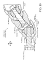
- FIGS. 4-5 show perspective views of a covered, sequentially rotating, multi-axis hinge assembly example in accordance with some implementations of the present concepts.
- FIG. 6 shows an exploded perspective view of a covered, sequentially rotating, multi-axis hinge assembly example in accordance with some implementations of the present concepts.
- FIG. 7 shows an exploded perspective view of a portion of the covered, sequentially rotating, multi-axis hinge assembly example of FIG. 6 .
- FIGS. 8-11 are sectional views of covered, sequentially rotating, multi-axis hinge assembly examples in accordance with some implementations of the present concepts.
- FIG. 12 shows another partial cut-away perspective view of an example device that includes a covered, sequentially rotating, multi-axis hinge assembly example in accordance with some implementations of the present concepts.
- the present concepts relate to computing devices employing multi-axis or multi-pivot hinges to rotatably secure portions of the computing device.
- the multi-pivot hinges can include hinge covers that can function to both protect the hinge from the user and the user from the hinge.
- the hinge covers can also contribute structurally to the hinge functionality and thus the hinge covers can be thought of as integrated with the multi-pivot hinges in that they (e.g., the hinge covers) can be dual function elements that contribute to both the hinge functionality and the hinge cover functionality.
- some implementations can control a relative order in which individual hinges rotate. One such case can cause the hinges to operate in a predefined order from first to last (e.g., sequentially).
- FIGS. 1-3 collectively show an example of a computing device 100 .
- computing device 100 has first and second portions 102 and 104 that are rotatably secured together by a covered, sequentially rotating, multi-axis hinge assembly 106 (e.g., CSRMA hinge assembly).
- FIG. 1 shows the computing device 100 from the ‘front’ and
- FIG. 2 shows the computing device from the ‘back.’
- FIGS. 1 and 2 show the computing device in a ‘closed’ or ‘storage’ position where the first and second portions are oriented relatively parallel to one another and juxtaposed relative to one another.
- the second portion 104 can be configured to be positioned on a generally horizontal surface (not specifically designated) and the first and second portions are generally parallel to one another and the horizontal surface.
- the CSRMA hinge assembly 106 can provide a footprint f c that is compact and easy to carry. The footprint is discussed more below relative to FIG. 3 .
- FIG. 3 shows a partial cut-away perspective view of computing device 100 in an ‘open’ or ‘deployed’ position.
- the first and second portions define an obtuse angle ⁇ relative to one another, as opposed to an angle close to zero in the closed position of FIGS. 1-2 .
- the CSRMA hinge assembly can include a set of integrated hinge covers 302 .
- adjacent integrated hinge covers can overlap one another to obscure the underlying elements during rotation.
- the integrated hinge covers 302 are integrated in that they function as hinge covers that are also structural hinge elements. Stated another way, the integrated hinge covers can be integral to the hinge function as well as functioning as hinge covers.
- This example includes four integrated hinge covers 302 .
- Other examples may include two, three, or five or more integrated hinge covers.
- individual integrated hinge covers 302 can be generally elongate (e.g., extending along a long axis relative to the y axis).
- Individual integrated hinge covers can also include a generally convex surface 304 and a generally opposing concave surface 306 (not all of the convex and concave surfaces are designated with particularity).
- the concave and convex surfaces can overlap and can allow rotational interaction between adjacent integrated hinge covers when the concave surface of one cover rotates relative to the convex surface of an adjacent integrated hinge cover.
- the computing device 100 can also include an input element or device 308 .
- the input device 308 is manifest as a keyboard 310 .
- the computing device can also include a display screen 312 , such as a touch sensitive display screen.
- the computing device can also include a processor 314 , memory/storage 316 , and/or a battery 318 , among other components. These elements can be positioned in the first portion 102 and/or second portion 104 .
- CSRMA hinge assembly 106 can be secured to the first and second portions 102 and 104 to allow rotation therebetween.
- the CSRMA hinge assembly 106 can be secured to the first and second portions in a relatively permanent manner (e.g., in a manner that is not intended to be readily separable by an end use consumer).
- the CSRMA hinge assembly 106 can be secured to the first and second portions in a relatively quickly attachable/detachable manner (e.g., in a manner that is intended to be readily separable by the end use consumer).
- a relatively quickly attachable/detachable manner e.g., in a manner that is intended to be readily separable by the end use consumer.
- this implementation of the CSRMA hinge assembly 106 is a progressive or sequential hinge that can increase a footprint of the computing device when the device is transitioned from the closed position of FIGS. 1-2 to the open position of FIG. 3 .
- This extended footprint feature can be especially valuable in this implementation where some or all of the electronic components, such as the display 312 , processor 314 , memory/storage 316 , and battery 318 are positioned in the first portion 102 .
- the extended footprint provided by the CSRMA hinge assembly can increase stability of the computing device and reduce the likelihood of the device tipping over backward in the deployed position from the weight of these components.
- This progressive or sequential nature of the CSRMA hinge assembly is described in more detail below relative to FIG. 9 .
- the sequential nature of the CSRMA hinge assembly 106 can create a foot 320 in the deployed position that can help stabilize the computing device 100 and decrease tipping (e.g., maintain the center of mass over the footprint).
- FIGS. 4-7 collectively show an example CSRMA hinge assembly 106 A.
- FIG. 4 shows the CSRMA hinge assembly 106 A in the opened or deployed position and
- FIG. 5 shows the CSRMA hinge assembly 106 A in the closed position.
- FIG. 6 shows an exploded view of the open position shown in FIG. 4 .
- Three integrated hinge covers 302 A are shown in these FIGS.
- the integrated hinge covers can be thought of as integrated in that in addition to the cover functionality the covers contribute to the hinge functionality.
- FIGS. 7-8 collectively show additional detail of portions of CSRMA hinge assembly 106 A.
- FIG. 7 shows an enlarged portion of the CSRMA hinge assembly 106 A as indicated in FIG. 6 . (Note that it is not practical due to space constraints on the drawing page to designate every instance of every element. Care has been taken to label at least one instance of each element in respect to each cover 302 ).
- FIG. 8 shows a sectional view taken along the xy reference plane.
- the illustrated CSRMA hinge assembly 106 A includes rotation elements in the form of friction engines 702 for positioning relative to respective covers 302 A.
- the friction engines 702 can include a friction shaft 704 riding on friction bands 706 .
- the friction shaft 704 can define the axis of rotation (AoR) (e.g., hinge axis) for the friction engine.
- AoR axis of rotation
- One such axis of rotation is labeled relative to friction engine 702 ( 3 ) in FIG. 7 and four axes of rotation are labeled in FIG. 8 . While specific rotation elements are shown and described, other rotation elements that can provide rotation around an axis of rotation and can operate cooperatively with other rotation elements are contemplated.
- the friction shaft 704 can include a centering pin 708 (labeled only relative to friction engine 702 ( 1 ) due to space constraints on the drawing page).
- the centering pin 708 can have first and second diameters 710 and 712 .
- First fasteners 714 can secure the friction bands 706 of the friction engine 702 to a respective integrated hinge cover 302 A as indicated by arrow 715 .
- a void 716 can be formed in the integrated hinge cover behind the friction engine 702 to prevent any portion of the first fastener that passes through the friction engine 702 from binding on the integrated hinge cover 302 A behind the friction engine and thereby limiting rotation of the friction engine. This aspect is described in more detail below relative to FIG. 11 .
- Second fasteners 718 can secure the friction shaft 704 of friction engine 702 to an adjacent integrated hinge cover 302 A (e.g., the second fasteners can rotatably interconnect adjacent integrated hinge covers). For instance, relative to integrated hinge cover 302 A( 2 ), the friction shaft 704 ( 2 ) can be secured to adjacent integrated hinge cover 302 A( 1 ) by second fastener 718 ( 1 ) as indicated by arrow 720 .
- the centering pin 708 (only labeled relative to friction engine 702 ( 1 )) of friction engine 702 ( 2 ) can pass through slot 717 ( 2 ) in integrated hinge cover 302 A( 2 ) and orient the friction engine relative to integrated hinge cover 302 A( 1 ) by the first diameter 710 ( 2 ) engaging alignment hole 722 ( 1 ) in integrated hinge cover 302 A( 1 ).
- the transition between the first and second dimensions 710 and 712 can create a ‘shoulder’ that limits compression of the friction shaft 704 against the adjacent integrated hinge cover 302 A.
- the relative dimension of the centering pin's second diameter 712 ( 2 ) to the height of the slot 717 ( 2 ) in the z reference direction can define a range of motion of the friction engine 702 ( 2 ).
- the height of the slot in the z reference direction relative to the second fastener 718 ( 1 ) can define the range of motion (e.g., degrees of rotation) of the friction engine 702 ( 2 ) (e.g., the profile of the slot is such that the second fastener 718 ( 1 ) and the second diameter 712 ( 2 ) of the centering pin 708 strike the cover 302 A( 2 ) at the same time). This aspect is described in more detail below relative to FIG. 9 .
- Sequencing pin 724 can ride in a hole 726 in integrated hinge cover 302 A and engage cam surfaces 728 and 730 of adjacent integrated hinge cover 302 A as indicated by arrow 732 . In this view only cam surfaces 728 are visible. However, this aspect is discussed in more detail below relative to FIG. 9 where both cam surfaces 728 and 730 are visible and labeled.
- FIGS. 6 and 7 show other hinge elements besides the integrated hinge covers 302 A.
- the integrated hinge covers effectively cover and obscure the other hinge elements. Covering the other hinge elements can protect the other hinge elements from damage, such as from a foreign object like a pen or zipper that might get caught in the hinge elements during rotation and damage the hinge elements. Similarly, without the protection offered by the integrated hinge covers, the user could get pinched by the other hinge elements during hinge rotation. Further, the integrated hinge covers can create a more aesthetically pleasing hinge appearance and thereby an overall aesthetically pleasing computing device appearance.
- the integrated hinge covers 302 A can be combined with the other hinge elements to form the CRSMA hinge assembly 106 A.
- the other hinge elements can be considered as a multi-pivot hinge assembly 734 that when combined with the integrated hinge covers 302 A can form the CRSMA hinge assembly 106 A.
- FIGS. 9-11 show sectional views through the xz reference plane as indicated in FIG. 8 , and are discussed collectively below.
- FIG. 9 shows two instances of CRSMA hinge assembly 106 A.
- Instance One shows a partially closed position similar to FIG. 1 .
- Instance Two is a partially deployed position similar to FIG. 3 .
- the point of interest illustrated in FIG. 9 is the sequential nature of the CRSMA hinge assembly starting proximate to second portion 104 A and progressing toward first portion 102 A.
- rotation of the integrated hinge covers 302 A starts with cover 302 A( 1 ), which in Instance One has already turned and is oriented parallel to the x reference direction.
- integrated hinge cover 302 A( 2 ) can rotate.
- pin 724 ( 2 ) prevents integrated hinge cover 302 A( 3 ) from rotating.
- pin 724 ( 2 ) is engaging cam surface 728 ( 2 ) and integrated hinge cover 302 A( 3 ) cannot rotate because the pin cannot evacuate away from cam surface 728 ( 2 ). Since the pin 724 ( 2 ) cannot move forward (in the positive x reference direction), engagement of the pin in the cam surface 728 ( 2 ) prevents rotation of integrated hinge cover 302 A( 3 ). As integrated hinge cover 302 A( 2 ) rotates into the horizontal position (e.g., similar to integrated hinge cover 302 A( 1 )) the pin 724 ( 2 ) can move forward (e.g., can be cammed forward by cam surface 728 ( 2 )) to evacuate away from cam surface 728 ( 2 ) until the pin engages cam surface 730 ( 1 ). At this point the pin 724 ( 2 ) is no longer blocking integrated hinge cover 302 A( 3 ) and rotation can continue to the point shown in Instance Two.
- the process can then repeat with another pin 724 positioned in integrated hinge cover 302 A( 3 ) and camming integrated hinge cover 302 A( 2 ) and first portion 102 A.
- the pins 724 in combination with cam surfaces 728 and 730 can be thought of as examples of timing elements or timed link elements 902 that control the sequential nature of the CSRMA hinge assembly (e.g., the order of rotation around the individual hinge axes).
- the integrated hinge covers 302 A can be thought of as hinged or linked elements and the timed link elements 902 can define the relative movements of the linked elements.
- CSRMA hinge assembly 106 A increases footprint (e.g., length) from f c in the closed position of Instance One to f d in the deployed position of Instance Two. This aspect was introduced above relative to FIGS. 1-3 .
- pin 724 ( 2 ) can have a shoulder 904 that has an outside diameter that is slightly smaller than a partial counter bore 906 formed in hole 726 ( 2 ) in integrated hinge cover 302 A( 2 ).
- the shoulder and counter bore can prevent pin 724 ( 2 ) from falling out of the CSRMA hinge assembly 106 A during the manufacturing process.
- FIG. 10 shows how dimensions of slot 717 formed in integrated hinge cover 302 A( 1 ) can define a range of rotation of the friction engine 702 .
- the dimensions are defined by the slot's upper surface 1002 and lower surface 1004 .
- second fastener 718 is secured to the friction engine's friction shaft 704 .
- the friction shaft 704 can rotate until the fastener 718 contacts the upper surface 1002 as illustrated.
- the friction shaft can rotate in the opposite direction through a defined range of motion or defined angle of rotation (e.g., number of degrees) until the fastener 718 contacts the lower surface 1004 .
- the defined range of the individual slots multiplied by the number of integrated hinge covers can define the range of rotation of the CSRMA hinge assembly 106 A. For instance, four integrated hinge covers having defined ranges of 45 degrees would provide overall hinge rotation of 180 degrees.
- FIG. 11 shows another view of CSRMA hinge assembly 106 A.
- This view shows first fasteners 714 securing friction bands 706 to integrated hinge cover 302 A.
- the fastener 714 ( 1 ) can secure integrated hinge cover 302 A( 1 ) to friction bands 706 ( 1 ) of friction engine 702 ( 1 ).
- Voids 716 ( 1 ) formed in line with fasteners 714 ( 1 ) can avoid situations where the fasteners inadvertently limit rotation of the friction engine relative to integrated hinge cover 302 A( 2 ) by the fastener binding on or otherwise contacting integrated hinge cover 302 A( 2 ).
- the voids 716 and/or other elements can be utilized to avoid rigidly (e.g., non-rotatably) fastening integrated hinge cover 302 A( 1 ) to integrated hinge cover 302 A( 2 ) and/or integrated hinge cover 302 A( 2 ) to integrated hinge cover 302 A( 3 ).
- individual integrated hinge covers 302 A can define a cavity 1102 .
- friction engine 702 ( 3 ) is positioned within the cavity 1102 ( 3 ).
- first fastener 714 ( 3 ) can serve to secure a non-moving portion of the friction engine (e.g., friction bands 706 ( 3 )) to integrated hinge cover 302 A( 3 ).
- Second fasteners 718 ( 3 ) can serve to secure a rotating portion (e.g., friction shaft 704 ( 3 )) to the adjacent integrated hinge cover 302 A( 2 ) to allow rotation between integrated hinge cover 302 A( 2 ) and integrated hinge cover 302 A( 3 ).
- these hinge components can be contained within the integrated hinge covers and/or pass between integrated hinge covers through the overlapping regions (e.g. convex surface of one hinge cover overlapping the concave surface of the adjacent integrated hinge cover).
- CSRMA hinge assembly implementations that employ a sequential hinge that uses sliding pins that cam off opposing covers to lock and unlock pins so that a multi-pivot hinge can roll and unroll in a controlled sequential manner that enables the hinge to be used as a foot to support a laptop or other device.
- the unrolling action can move the device fulcrum backwards providing a longer wheel base or foot print for the device in turn making the device less likely to tip over when a user interacts with the touch screen, for example.
- some of the present implementations can be characterized as employing a multi-pivot hinge that includes multiple pivots (e.g., pivot axes) and links between integrated hinge covers.
- a sliding lock between each pivot and link can be moved into position via camming action embedded within the link that forces a lock fore and aft (e.g., in the x reference direction) to lock and unlock adjacent links.
- the locks can be staggered in adjacent integrate hinge covers to enable progressive communication between links.
- this configuration can provide higher torque when opening a closed device and also when at the working or deployed angle (>90 degrees).
- the display moment is highest when the display is close to horizontal or when a touch force is being applied to it.
- multiple friction hinges can be arranged in series with a staggered formation on either side of the device in a CSRMA hinge assembly.
- Mechanical stops e.g., upper surface 1002 and lower surface 1004 of FIG. 10
- Sliding locking or linking elements e.g., pins 724
- spacers can be employed between each hinge cover to reduce and/or prevent adjacent integrated hinge covers from rubbing against each other.
- FIG. 12 shows a view that is similar to the view of FIG. 3 .
- computing device 100 B includes first and second portions 102 B and 104 B that are rotatably secured by CSRMA hinge assembly 106 B.
- the CSRMA hinge assembly 106 B is configured to allow an end user consumer to easily detach either or both of the first and second portions 102 B and 104 B from the CSRMA hinge assembly 106 B as indicated by arrow 1202 .
- the CSRMA hinge assembly 106 B can include a quick attach/detach assembly 1204 .
- the quick attach/detach assembly 1204 may include cooperatively operating elements 1206 and 1208 located on the first portion 102 B and the CSRMA hinge assembly 106 B, respectively.
- element 1206 can be manifest as a latch and element 1208 can be manifest as a receiver.
- the latch can engage the receiver to removeably couple the first portion 102 B with the CSRMA hinge assembly 106 B.
- the elements 1206 and 1208 may magnetically couple to one another in a manner that can be overcome by the user to separate the first portion from the CSRMA hinge assembly.
- Other quick attach/detach assemblies 1204 are contemplated. Note further that alternatively or additionally to mechanically coupling the CSRMA hinge assembly 106 B to the first and/or second portions, the quick attach/detach assembly 1204 can detachably electrically couple electronic components of the first and second portions. For instance, the quick attach/detach assembly 1204 may electrically couple processor 314 , storage/memory 316 , and/or battery 318 from the first portion 102 B to a video processor 1210 in the second portion 104 B.
- first portion 102 B may be operated as a stand-alone tablet device, and then may be attached to second portion 104 B via CSRMA hinge assembly 106 B to form a device more akin to a laptop device.
- a user may also be able to exchange first portion 102 B or second portion 104 B for application-specific devices.
- an individual second portion may include a keyboard and/or a touchscreen.
- the user may attach a first touchscreen as the first portion and a second touchscreen as second portion, and utilize the device like a book.
- a user may attach a touchscreen as the first portion and an input device, comprising a keyboard and trackpad, as the second portion, and utilize the device like a laptop.
- Other configurations and implementations are contemplated.
- Individual elements of the CSRMA hinge assembly can be made from various materials, such as sheet metals, die cast metals, and/or molded plastics, among others, or any combination of these materials.
- CSRMA hinge assemblies can be utilized with any type of computing device, such as but not limited to notebook computers, smart phones, wearable smart devices, and/or other types of existing, developing, and/or yet to be developed computing devices.
- One example is manifest as a first portion and a second portion.
- the example can also include a set of rotatably interconnected elongate covers securing the first and second portions, individual elongate covers can define a cavity.
- the example can further include a multi-pivot hinge assembly comprising a set of hinge elements. An individual hinge element is positioned within the cavity of a first individual elongate cover and rotatably secured between the first individual elongate cover and a second adjacent elongate cover effective that the individual hinge element pivots around a hinge axis that is parallel to the elongate cover.
- timing elements are positioned within the first individual elongate cover and extend to the second adjacent elongate cover.
- hinge elements comprise friction engines.
- the second portion defines a footprint of the computing device in the storage position as measured transverse the elongate covers and in the deployed position the set of rotatably interconnected elongate covers extends the footprint.
- Another example is manifest as a first portion that includes a display screen and a second portion that includes an input device.
- the example can include a covered sequentially rotating multi-pivot hinge assembly rotatably securing the first portion and the second portion in a manner that extends a footprint of the computing device as the first portion is rotated away from the second portion.
- the second portion is configured to be positioned on a horizontal surface and the first portion is configured to be rotated relative to the horizontal surface from a storage position to a deployed position.
- the extended footprint maintains a center of mass of the computing device above the extended footprint in the deployed position.
- the second portion is configured to be positioned on a horizontal surface and the first portion is configured to be positioned over the second portion in a generally horizontal orientation and to be rotated relative to the horizontal surface to a deployed position that is obtuse to the horizontal surface.
- the extended footprint maintains a center of mass of the computing device above the extended footprint in the deployed position and wherein the covered sequentially rotating multi-pivot hinge assembly rotates around a set of hinge axes when the first portion is rotated from the horizontal orientation starting with a first hinge axis closest to the second portion and sequentially progressing to a second hinge axis farther from the second portion upon completion of a defined angle of rotation by the first hinge axis.
- the covered sequentially rotating multi-pivot hinge assembly further comprises a set of overlapping covers.
- any combination of the above and/or below examples where the overlapping covers contribute to a rotation functionality of the covered sequentially rotating multi-pivot hinge assembly and a sequential timing functionality of the covered sequentially rotating multi-pivot hinge assembly.
- the example is manifest as a first portion and a second portion.
- the example can also include a multi-axis hinge assembly securing the first portion and the second portion.
- the multi-axis hinge assembly includes overlapping covers and timed link elements positioned in the overlapping covers that define an order of rotation of individual axes of the multi-axis hinge assembly.
- timed link elements define the order of rotation by limiting rotation initially to an individual axis of rotation nearest the second portion as the first and second portions are rotated away from one another and further limiting rotation initially to another individual axis of rotation nearest the first portion as the first and second portions are rotated toward one another.
- first individual timed link element interacts with first and second individual covers.
- the first individual timed link element blocks rotation of the second individual cover until the first individual cover has completed a defined angle of rotation.
- first and second individual covers are adjacent to one another or where a third individual cover is interposed between the first and second individual covers.
- any combination of the above and/or below examples further including a quick attach/detach assembly configured to removably couple the first portion to the multi-axis hinge assembly and/or the second portion to the multi-axis hinge assembly.
Landscapes
- Engineering & Computer Science (AREA)
- Computer Hardware Design (AREA)
- Theoretical Computer Science (AREA)
- Physics & Mathematics (AREA)
- Human Computer Interaction (AREA)
- General Engineering & Computer Science (AREA)
- General Physics & Mathematics (AREA)
- Signal Processing (AREA)
- Mathematical Physics (AREA)
- Casings For Electric Apparatus (AREA)
- Pivots And Pivotal Connections (AREA)
- Telephone Set Structure (AREA)
- Mechanical Engineering (AREA)
Abstract
Description
Claims (19)
Priority Applications (6)
| Application Number | Priority Date | Filing Date | Title |
|---|---|---|---|
| US14/538,786 US9625953B2 (en) | 2014-11-11 | 2014-11-11 | Covered multi-pivot hinge |
| PCT/US2015/059799 WO2016077254A1 (en) | 2014-11-11 | 2015-11-10 | Covered multi-pivot hinge |
| EP15797753.9A EP3218783B1 (en) | 2014-11-11 | 2015-11-10 | Covered multi-pivot hinge |
| JP2017519501A JP6618533B2 (en) | 2014-11-11 | 2015-11-10 | Coated multi-pivot hinge |
| CN201580061294.1A CN107003695B (en) | 2014-11-11 | 2015-11-10 | Multi-pivot hinge with cover |
| KR1020177015834A KR102498940B1 (en) | 2014-11-11 | 2015-11-10 | Covered multi-pivot hinge |
Applications Claiming Priority (1)
| Application Number | Priority Date | Filing Date | Title |
|---|---|---|---|
| US14/538,786 US9625953B2 (en) | 2014-11-11 | 2014-11-11 | Covered multi-pivot hinge |
Publications (2)
| Publication Number | Publication Date |
|---|---|
| US20160132076A1 US20160132076A1 (en) | 2016-05-12 |
| US9625953B2 true US9625953B2 (en) | 2017-04-18 |
Family
ID=54608956
Family Applications (1)
| Application Number | Title | Priority Date | Filing Date |
|---|---|---|---|
| US14/538,786 Expired - Fee Related US9625953B2 (en) | 2014-11-11 | 2014-11-11 | Covered multi-pivot hinge |
Country Status (6)
| Country | Link |
|---|---|
| US (1) | US9625953B2 (en) |
| EP (1) | EP3218783B1 (en) |
| JP (1) | JP6618533B2 (en) |
| KR (1) | KR102498940B1 (en) |
| CN (1) | CN107003695B (en) |
| WO (1) | WO2016077254A1 (en) |
Cited By (23)
| Publication number | Priority date | Publication date | Assignee | Title |
|---|---|---|---|---|
| US20160357226A1 (en) * | 2014-11-26 | 2016-12-08 | Microsoft Technology Licensing, Llc | Multi-pivot hinge |
| US9898051B2 (en) * | 2014-10-17 | 2018-02-20 | Seneka Co., Ltd. | Hinge device |
| US9910465B2 (en) | 2014-11-11 | 2018-03-06 | Microsoft Technology Licensing, Llc | Covered radius hinge |
| US20180242446A1 (en) * | 2017-02-23 | 2018-08-23 | Samsung Electronics Co., Ltd. | Foldable electronic device and control method thereof |
| US20180270971A1 (en) * | 2016-09-13 | 2018-09-20 | Samsung Electronics Co., Ltd. | Flexible display electronic device |
| US10162389B2 (en) | 2015-09-25 | 2018-12-25 | Microsoft Technology Licensing, Llc | Covered multi-axis hinge |
| US10174534B2 (en) | 2015-01-27 | 2019-01-08 | Microsoft Technology Licensing, Llc | Multi-pivot hinge |
| US10227808B2 (en) | 2015-11-20 | 2019-03-12 | Microsoft Technology Licensing, Llc | Hinged device |
| US10241548B2 (en) | 2016-12-09 | 2019-03-26 | Microsoft Technology Licensing, Llc | Computing device employing a self-spacing hinge assembly |
| US10253804B2 (en) | 2017-01-24 | 2019-04-09 | Microsoft Technology Licensing, Llc | Hinged device |
| US10296044B2 (en) | 2017-06-08 | 2019-05-21 | Microsoft Technology Licensing, Llc | Hinged device |
| US10344510B2 (en) | 2017-06-16 | 2019-07-09 | Microsoft Technology Licensing, Llc | Hinged device |
| US10364598B2 (en) | 2016-09-02 | 2019-07-30 | Microsoft Technology Licensing, Llc | Hinged device |
| US20190292827A1 (en) * | 2018-03-21 | 2019-09-26 | Microsoft Technology Licensing, Llc | Low-pressure friction hinge |
| US10437293B2 (en) | 2016-09-23 | 2019-10-08 | Microsoft Technology Licensing, Llc | Multi-axis hinge |
| US10474203B2 (en) | 2016-09-01 | 2019-11-12 | Microsoft Technology Licensing, Llc | Hinged device |
| US10641318B2 (en) | 2016-12-09 | 2020-05-05 | Microsoft Technology Licensing, Llc | Hinged device |
| USD904331S1 (en) * | 2018-11-29 | 2020-12-08 | Lg Electronics Inc. | Mobile phone |
| USD949147S1 (en) * | 2017-12-27 | 2022-04-19 | Samsung Display Co., Ltd. | Display device |
| US20230031086A1 (en) * | 2021-07-28 | 2023-02-02 | Tpk Advanced Solutions Inc. | Foldable electronic device |
| US11573610B2 (en) * | 2019-12-26 | 2023-02-07 | Fositek Corporation | Rotary shaft link assembly structure |
| US20230099982A1 (en) * | 2021-09-24 | 2023-03-30 | Acer Incorporated | Foldable electronic device |
| USD988317S1 (en) * | 2017-05-31 | 2023-06-06 | Samsung Display Co., Ltd. | Display device |
Families Citing this family (40)
| Publication number | Priority date | Publication date | Assignee | Title |
|---|---|---|---|---|
| USD778864S1 (en) * | 2014-03-26 | 2017-02-14 | Lg Electronics Inc. | Cellular phone |
| USD772835S1 (en) * | 2014-03-26 | 2016-11-29 | Lg Electronics Inc. | Cellular phone |
| USD772188S1 (en) * | 2014-03-26 | 2016-11-22 | Lg Electronics Inc. | Cellular phone including pair of interchangeable components |
| USD778865S1 (en) * | 2014-03-26 | 2017-02-14 | Lg Electronics Inc. | Cellular phone |
| US9625953B2 (en) | 2014-11-11 | 2017-04-18 | Microsoft Technology Licensing, Llc | Covered multi-pivot hinge |
| US9851759B2 (en) | 2014-12-31 | 2017-12-26 | Microsoft Technology Licensing, Llc | Multi-pivot hinge cover |
| US10296054B2 (en) * | 2016-02-09 | 2019-05-21 | Lenovo (Singapore) Pte. Ltd. | Lobster hinge assembly |
| US10126785B2 (en) | 2016-08-11 | 2018-11-13 | Microsoft Technology Licensing, Llc | Cam lock hinge for determinant movement |
| KR102630498B1 (en) * | 2016-08-12 | 2024-01-31 | 삼성전자주식회사 | Electronic device including flexible display |
| US10024090B2 (en) * | 2016-09-02 | 2018-07-17 | Microsoft Technology Licensing, Llc | Removable couplers for assembly of an integrated multi-pivot hinge module |
| US10067530B2 (en) * | 2016-09-02 | 2018-09-04 | Microsoft Technology Licensing, Llc | Integrated multi-pivot hinge module |
| TWI621786B (en) * | 2017-02-18 | 2018-04-21 | 華碩電腦股份有限公司 | Multi-axis hinge and electronic device with the same |
| US9964995B1 (en) | 2017-06-21 | 2018-05-08 | Dell Products L.P. | Dynamic antenna orientation with a flexible information handling system display |
| US10082838B1 (en) | 2017-06-21 | 2018-09-25 | Dell Products L.P. | Flexible information handling system display external hinge structure |
| US10015897B1 (en) | 2017-06-21 | 2018-07-03 | Dell Products L.P. | Flexible information handling system display sliding frame |
| US10082839B1 (en) | 2017-06-21 | 2018-09-25 | Dell Products L.P. | Flexible information handling system display hinge and ramp support structure |
| US10120421B1 (en) | 2017-06-21 | 2018-11-06 | Dell Products L.P. | Flexible information handling system display |
| US10223959B2 (en) * | 2017-07-25 | 2019-03-05 | Dell Products L.P. | Information handling system integrated overlapped foldable display |
| KR102369212B1 (en) * | 2017-07-28 | 2022-03-03 | 삼성디스플레이 주식회사 | Display apparatus |
| US11079807B1 (en) * | 2017-08-03 | 2021-08-03 | Apple Inc. | Friction roller hinge for electronic devices and method for making roller and spacer elements |
| JP7024991B2 (en) * | 2017-09-21 | 2022-02-24 | 株式会社ナチュラレーザ・ワン | Switchgear and terminal device |
| KR102414445B1 (en) | 2017-12-27 | 2022-06-29 | 삼성전자주식회사 | Convertible-type electronic apparatus with dual-axis hinge device |
| CN108089641B (en) * | 2018-01-02 | 2021-04-13 | 联想(北京)有限公司 | Rotating shaft and electronic equipment provided with same |
| TWM563489U (en) * | 2018-03-07 | 2018-07-11 | 富世達股份有限公司 | Linkage positioning mechanism and flexible electronic device |
| TWI672578B (en) * | 2018-05-30 | 2019-09-21 | 宏碁股份有限公司 | Hinge mechanism |
| KR102512482B1 (en) * | 2018-07-31 | 2023-03-21 | 엘지디스플레이 주식회사 | Foldable Display |
| US10754394B2 (en) * | 2018-10-30 | 2020-08-25 | Microsoft Technology Licensing, Llc | Hinged device |
| US10928863B2 (en) | 2019-01-14 | 2021-02-23 | Dell Products L.P. | Portable information handling system midframe to sliding frame assembly |
| US10817030B2 (en) | 2019-01-14 | 2020-10-27 | Dell Products L.P. | Portable information handling system flexible display with alternating slide support frame |
| US10754395B2 (en) | 2019-01-17 | 2020-08-25 | Dell Products L.P. | Multi-axis hinge translation to adjust housing position relative to flexible display position |
| CN110012131A (en) * | 2019-02-28 | 2019-07-12 | 努比亚技术有限公司 | A kind of shaft |
| CN109889633A (en) * | 2019-02-28 | 2019-06-14 | 努比亚技术有限公司 | A kind of shaft |
| CN110035144A (en) * | 2019-02-28 | 2019-07-19 | 努比亚技术有限公司 | A kind of shaft |
| KR102733499B1 (en) * | 2019-04-29 | 2024-11-26 | 삼성디스플레이 주식회사 | Display device |
| KR102794470B1 (en) * | 2019-05-10 | 2025-04-11 | 삼성전자 주식회사 | Housing, manufacturing method thereof, and electronic device including the same |
| JP6792042B1 (en) * | 2019-10-18 | 2020-11-25 | レノボ・シンガポール・プライベート・リミテッド | Portable information equipment |
| WO2021078364A1 (en) * | 2019-10-22 | 2021-04-29 | Huawei Technologies Co., Ltd. | Bidirectionally foldable hinge assembly for electronic device |
| EP4026305B9 (en) * | 2019-10-22 | 2025-03-05 | Huawei Technologies Co., Ltd. | Hinge assembly for controlled folding of an electronic device |
| TWI730766B (en) * | 2020-05-15 | 2021-06-11 | 仁寶電腦工業股份有限公司 | Electronic device |
| CN116136230B (en) * | 2021-11-16 | 2025-08-05 | 北京小米移动软件有限公司 | Support components, foldable displays, and terminal devices |
Citations (79)
| Publication number | Priority date | Publication date | Assignee | Title |
|---|---|---|---|---|
| US4611710A (en) | 1983-01-14 | 1986-09-16 | Tsubakimoto Chain Co. | Hinge-type table top chain |
| US4711046A (en) | 1985-02-27 | 1987-12-08 | Herrgord Donald E | Lightweight multi-panel display |
| US5056192A (en) | 1989-07-24 | 1991-10-15 | Grass Ag | Protective cover for single and multiple articulation hinges |
| US5229921A (en) | 1991-04-23 | 1993-07-20 | Ta Triumph-Adler Aktiengesellschaft | Portable data processing device with turnable display having two vertical positions |
| US5509590A (en) | 1994-05-12 | 1996-04-23 | Waco Corporation | Collapsible baby carrier device |
| EP0844357A1 (en) | 1996-11-25 | 1998-05-27 | Stein, Klaus | Protective strip for sectional door panel |
| US5796575A (en) | 1992-12-21 | 1998-08-18 | Hewlett-Packard Company | Portable computer with hinged cover having a window |
| US5845366A (en) | 1996-07-26 | 1998-12-08 | Nec Corporation | Hinge structure for portable type electronic equipment |
| US5987704A (en) | 1998-04-15 | 1999-11-23 | Apple Computer, Inc. | Dual axis hinge apparatus with braking mechanism |
| US6223393B1 (en) | 1999-07-09 | 2001-05-01 | International Business Machines Corporation | Redundant hinge element for a notebook computer |
| US6470532B2 (en) | 2000-02-29 | 2002-10-29 | Torqmaster, Inc. | Cam hinge with controlled friction for improved cam operation |
| US6505382B1 (en) | 1999-05-14 | 2003-01-14 | Apple Computer, Inc. | Hinge apparatus with cam mechanism |
| US6527036B1 (en) | 2001-06-15 | 2003-03-04 | Thomas M. Welsh | Pinch resistant hinge and joint construction for upward acting sectional doors |
| EP1340879A2 (en) | 2002-03-01 | 2003-09-03 | Hild Tortechnik GmbH | Hinged connection |
| US6754081B2 (en) | 2002-01-22 | 2004-06-22 | Edward Rude | Pop-up friction hinge having multiple levels of torque |
| US6757160B2 (en) | 2002-06-06 | 2004-06-29 | Hewlett-Packard Development Company, L.P. | Flexible door for use with an electronic device |
| EP1464784A1 (en) | 2003-04-04 | 2004-10-06 | Groep Stevens International, Naamloze Vennootschap | Strip hinge composed of flexible strips of fiber reinforced synthetic material |
| US6831229B1 (en) | 2003-09-11 | 2004-12-14 | Nokia Corporation | Hinge cover mechanism for folding casings with lift function |
| US20050122671A1 (en) | 2003-12-09 | 2005-06-09 | Homer Steven S. | Electronic device with improved hinge |
| US6966435B2 (en) | 2001-11-08 | 2005-11-22 | Laitram, L.L.C. | Oriented polymer hinge pins in modular plastic conveyor belts |
| US20060079277A1 (en) | 1997-04-04 | 2006-04-13 | Ditzik Richard J | Notebook computer with replaceable battery unit |
| US20070039132A1 (en) | 2005-08-22 | 2007-02-22 | Samsung Electronics Co., Ltd. | Hinge device for portable terminal and portable terminal having the same |
| US20070049376A1 (en) | 2005-08-23 | 2007-03-01 | Samsung Electronics Co., Ltd | Swing hinge module for portable communication device |
| US20070117600A1 (en) | 2005-11-21 | 2007-05-24 | Robertson William H Jr | Flexible hinge for portable electronic device |
| US7227741B2 (en) | 2004-10-15 | 2007-06-05 | Dell Products L.P. | Composite cover for notebook-type computer |
| US7251129B2 (en) | 2005-06-08 | 2007-07-31 | Quanta Computer Inc. | Two-way auto-locking tablet PC hinge |
| US7293380B2 (en) | 2005-09-19 | 2007-11-13 | Royal Consumer Products Llc | Portable display device with integral support foot |
| US20080174089A1 (en) | 2007-01-21 | 2008-07-24 | Lane Ekberg | Apparatus, system, and method for a collapsing approach ski |
| US7418766B2 (en) | 2004-12-22 | 2008-09-02 | Xerox Corporation | Hinge with tandem pivot structure motion lock and override |
| US7520025B2 (en) | 2007-07-31 | 2009-04-21 | Shin Zu Shing Co., Ltd. | Hinge for a notebook extension pad |
| US7584524B2 (en) | 2007-07-25 | 2009-09-08 | Shin Zu Shing Co., Ltd. | Hinge for a notebook extension pad |
| US7636985B2 (en) | 2007-10-30 | 2009-12-29 | Dan Greenbank | Dual stage hidden hinge |
| US20100154171A1 (en) | 2008-12-18 | 2010-06-24 | Motorola Inc. | Design and Implementation of Friction Hinge with a Range of Motion and Detent Separation Greater than 180 Degrees |
| US20100232100A1 (en) | 2009-03-16 | 2010-09-16 | Yohei Fukuma | Electronic Apparatus |
| US20110000136A1 (en) | 2008-03-21 | 2011-01-06 | Giancarlo Brun | Articulation means |
| US20110177850A1 (en) | 2010-01-15 | 2011-07-21 | Research In Motion Limited | Mobile communication device having overlapping first and second body members |
| US8024843B2 (en) | 2008-03-07 | 2011-09-27 | Sony Ericsson Mobile Communications Japan, Inc. | Biaxial hinge device and portable terminal device |
| US20110292605A1 (en) | 2010-06-01 | 2011-12-01 | Kuan-Chih Chen | Heat-dissipating hinge and a portable electronic device with the same |
| US8122970B2 (en) | 2009-12-07 | 2012-02-28 | Agco Corporation | Duplex frame hinge for farm implement |
| US20120147542A1 (en) | 2004-07-20 | 2012-06-14 | Kim Si-Han | Portable display device |
| US20120279014A1 (en) | 2011-05-03 | 2012-11-08 | Anders Carlsson | Aligning multiple pivot pin system and method therefor |
| US20130014346A1 (en) | 2011-07-13 | 2013-01-17 | Samsung Electronics Co., Ltd. | Gear cam mounting device in dual-hinge device for a portable terminal |
| US20130081229A1 (en) | 2010-06-09 | 2013-04-04 | Mitsubishi Steel Mfg. Co., Ltd. | Hinge device |
| US8441791B2 (en) | 2010-12-23 | 2013-05-14 | Microsoft Corporation | Double hinge radial cams |
| US20130135809A1 (en) | 2011-11-28 | 2013-05-30 | Beijing Lenovo Software Ltd. | Terminal apparatus |
| US20130139355A1 (en) | 2011-12-06 | 2013-06-06 | Compal Electronics, Inc. | Hinge mechanism and foldable electronic device |
| US8467838B2 (en) | 2009-11-20 | 2013-06-18 | Research In Motion Limited | Portable electronic device |
| US20130152342A1 (en) | 2011-12-14 | 2013-06-20 | Samsung Electronics Co., Ltd. | Gear hinge device for portable apparatus |
| US20130216740A1 (en) | 2012-02-16 | 2013-08-22 | Apple Inc. | Interlocking flexible segments formed from a rigid material |
| US20130219663A1 (en) | 2012-02-27 | 2013-08-29 | Lenovo (Beijing) Co., Ltd. | Hinge Apparatus And Electronic Device Comprising It |
| US8624844B2 (en) | 2008-04-01 | 2014-01-07 | Litl Llc | Portable computer with multiple display configurations |
| US8649166B2 (en) | 2011-01-11 | 2014-02-11 | Z124 | Multi-positionable portable computer |
| US20140084772A1 (en) | 2011-03-31 | 2014-03-27 | Ming Zhang | Automatic hinge locking assembly for electronic device |
| US8687359B2 (en) | 2008-10-13 | 2014-04-01 | Apple Inc. | Portable computer unified top case |
| US20140111954A1 (en) | 2012-10-19 | 2014-04-24 | Samsung Display Co., Ltd. | Foldable display device |
| KR20140049911A (en) | 2012-10-18 | 2014-04-28 | 이유구 | Flexible hinge device and flexible hinge device with flexible display devices |
| US8743538B2 (en) | 2011-10-14 | 2014-06-03 | Hewlett-Packard Development Company, L.P. | Protective hinge cover for a mobile computing device |
| US20140160055A1 (en) | 2012-12-12 | 2014-06-12 | Jeffrey Margolis | Wearable multi-modal input device for augmented reality |
| US20140174227A1 (en) | 2012-12-21 | 2014-06-26 | First Dome Corporation | Synchronous folding device |
| US20140196253A1 (en) | 2013-01-11 | 2014-07-17 | Prexco Co., Ltd. | Hinge for display device |
| US20140196254A1 (en) * | 2013-01-11 | 2014-07-17 | Prexco Co., Ltd. | Foldable flexible display device |
| US8797727B2 (en) | 2011-09-15 | 2014-08-05 | Hewlett-Packard Development Company, L.P. | Laptops and methods of protecting electronic components of a laptop |
| US20140217875A1 (en) | 2013-02-07 | 2014-08-07 | Samsung Electronics Co., Ltd | Portable electronic device |
| US8804324B2 (en) | 2011-06-03 | 2014-08-12 | Microsoft Corporation | Flexible display overcenter assembly |
| EP2765479A2 (en) | 2013-02-08 | 2014-08-13 | Samsung Electronics Co., Ltd. | Flexible portable terminal |
| US20140239065A1 (en) | 2011-07-18 | 2014-08-28 | Tiger T G Zhou | Wearable personal digital device with changeable bendable battery and expandable display used as standalone electronic payment card |
| US20140245569A1 (en) | 2013-03-04 | 2014-09-04 | Shin Zu Shing Co., Ltd. | Hinge device |
| US8854834B2 (en) | 2010-11-16 | 2014-10-07 | Flextronics Ap, Llc | Dual screen folding display hinge |
| US20150092331A1 (en) | 2013-09-27 | 2015-04-02 | Lenovo (Singapore) Pte. Ltd. | Electronic device with damage prevention features |
| US20150176317A1 (en) | 2013-12-23 | 2015-06-25 | Samsung Electronics Co., Ltd | Electronic apparatus having hinge assemblies with cover units |
| CN204553530U (en) | 2015-02-15 | 2015-08-12 | 杭州安费诺飞凤通信部品有限公司 | Multi-section type sequential movements friction shaft hinge and mobile electronic product terminal |
| US20150277506A1 (en) | 2014-03-29 | 2015-10-01 | Bok Eng Cheah | Micro-hinge for an electronic device |
| US20150361696A1 (en) | 2014-06-12 | 2015-12-17 | Microsoft Corporation | Flexible display computing device |
| US20150362956A1 (en) | 2014-06-12 | 2015-12-17 | Microsoft Corporation | Radius hinge |
| US20160132075A1 (en) | 2014-11-11 | 2016-05-12 | Microsoft Technology Licensing, Llc | Covered radius hinge |
| WO2016077254A1 (en) | 2014-11-11 | 2016-05-19 | Microsoft Technology Licensing, Llc | Covered multi-pivot hinge |
| US20160147267A1 (en) | 2014-11-26 | 2016-05-26 | Microsoft Technology Licensing, Llc | Multi-pivot hinge |
| US20160187935A1 (en) | 2014-12-31 | 2016-06-30 | Microsoft Technology Licensing, Llc | Multi-pivot hinge cover |
| US20160215541A1 (en) | 2015-01-27 | 2016-07-28 | Microsoft Technology Licensing, Llc | Multi-pivot hinge |
Family Cites Families (5)
| Publication number | Priority date | Publication date | Assignee | Title |
|---|---|---|---|---|
| KR100849284B1 (en) * | 2006-08-11 | 2008-07-29 | 삼성전자주식회사 | Biaxial rotary folder type mobile communication terminal and its hinge device |
| JP5704613B2 (en) * | 2012-05-30 | 2015-04-22 | 株式会社ナチュラレーザ・ワン | 2-axis hinge |
| KR101452869B1 (en) * | 2013-01-11 | 2014-10-22 | (주) 프렉코 | Foldable flexible display device |
| KR102089978B1 (en) * | 2013-02-07 | 2020-03-17 | 삼성전자주식회사 | Portable electrnic device |
| US20150074944A1 (en) * | 2013-09-16 | 2015-03-19 | Marine Town Inc. | Covered hinge assembly |
-
2014
- 2014-11-11 US US14/538,786 patent/US9625953B2/en not_active Expired - Fee Related
-
2015
- 2015-11-10 KR KR1020177015834A patent/KR102498940B1/en active Active
- 2015-11-10 WO PCT/US2015/059799 patent/WO2016077254A1/en not_active Ceased
- 2015-11-10 EP EP15797753.9A patent/EP3218783B1/en active Active
- 2015-11-10 JP JP2017519501A patent/JP6618533B2/en active Active
- 2015-11-10 CN CN201580061294.1A patent/CN107003695B/en active Active
Patent Citations (84)
| Publication number | Priority date | Publication date | Assignee | Title |
|---|---|---|---|---|
| US4611710A (en) | 1983-01-14 | 1986-09-16 | Tsubakimoto Chain Co. | Hinge-type table top chain |
| US4711046A (en) | 1985-02-27 | 1987-12-08 | Herrgord Donald E | Lightweight multi-panel display |
| US5056192A (en) | 1989-07-24 | 1991-10-15 | Grass Ag | Protective cover for single and multiple articulation hinges |
| US5229921A (en) | 1991-04-23 | 1993-07-20 | Ta Triumph-Adler Aktiengesellschaft | Portable data processing device with turnable display having two vertical positions |
| US5796575A (en) | 1992-12-21 | 1998-08-18 | Hewlett-Packard Company | Portable computer with hinged cover having a window |
| US5509590A (en) | 1994-05-12 | 1996-04-23 | Waco Corporation | Collapsible baby carrier device |
| US5845366A (en) | 1996-07-26 | 1998-12-08 | Nec Corporation | Hinge structure for portable type electronic equipment |
| EP0844357A1 (en) | 1996-11-25 | 1998-05-27 | Stein, Klaus | Protective strip for sectional door panel |
| US20060079277A1 (en) | 1997-04-04 | 2006-04-13 | Ditzik Richard J | Notebook computer with replaceable battery unit |
| US5987704A (en) | 1998-04-15 | 1999-11-23 | Apple Computer, Inc. | Dual axis hinge apparatus with braking mechanism |
| US6505382B1 (en) | 1999-05-14 | 2003-01-14 | Apple Computer, Inc. | Hinge apparatus with cam mechanism |
| US6223393B1 (en) | 1999-07-09 | 2001-05-01 | International Business Machines Corporation | Redundant hinge element for a notebook computer |
| US6470532B2 (en) | 2000-02-29 | 2002-10-29 | Torqmaster, Inc. | Cam hinge with controlled friction for improved cam operation |
| US6527036B1 (en) | 2001-06-15 | 2003-03-04 | Thomas M. Welsh | Pinch resistant hinge and joint construction for upward acting sectional doors |
| US6966435B2 (en) | 2001-11-08 | 2005-11-22 | Laitram, L.L.C. | Oriented polymer hinge pins in modular plastic conveyor belts |
| US6754081B2 (en) | 2002-01-22 | 2004-06-22 | Edward Rude | Pop-up friction hinge having multiple levels of torque |
| EP1340879A2 (en) | 2002-03-01 | 2003-09-03 | Hild Tortechnik GmbH | Hinged connection |
| US6757160B2 (en) | 2002-06-06 | 2004-06-29 | Hewlett-Packard Development Company, L.P. | Flexible door for use with an electronic device |
| EP1464784A1 (en) | 2003-04-04 | 2004-10-06 | Groep Stevens International, Naamloze Vennootschap | Strip hinge composed of flexible strips of fiber reinforced synthetic material |
| US6831229B1 (en) | 2003-09-11 | 2004-12-14 | Nokia Corporation | Hinge cover mechanism for folding casings with lift function |
| US20050122671A1 (en) | 2003-12-09 | 2005-06-09 | Homer Steven S. | Electronic device with improved hinge |
| US20120147542A1 (en) | 2004-07-20 | 2012-06-14 | Kim Si-Han | Portable display device |
| US7227741B2 (en) | 2004-10-15 | 2007-06-05 | Dell Products L.P. | Composite cover for notebook-type computer |
| US7418766B2 (en) | 2004-12-22 | 2008-09-02 | Xerox Corporation | Hinge with tandem pivot structure motion lock and override |
| US7251129B2 (en) | 2005-06-08 | 2007-07-31 | Quanta Computer Inc. | Two-way auto-locking tablet PC hinge |
| US20070039132A1 (en) | 2005-08-22 | 2007-02-22 | Samsung Electronics Co., Ltd. | Hinge device for portable terminal and portable terminal having the same |
| US20070049376A1 (en) | 2005-08-23 | 2007-03-01 | Samsung Electronics Co., Ltd | Swing hinge module for portable communication device |
| US7293380B2 (en) | 2005-09-19 | 2007-11-13 | Royal Consumer Products Llc | Portable display device with integral support foot |
| US20070117600A1 (en) | 2005-11-21 | 2007-05-24 | Robertson William H Jr | Flexible hinge for portable electronic device |
| US20080174089A1 (en) | 2007-01-21 | 2008-07-24 | Lane Ekberg | Apparatus, system, and method for a collapsing approach ski |
| US7584524B2 (en) | 2007-07-25 | 2009-09-08 | Shin Zu Shing Co., Ltd. | Hinge for a notebook extension pad |
| US7520025B2 (en) | 2007-07-31 | 2009-04-21 | Shin Zu Shing Co., Ltd. | Hinge for a notebook extension pad |
| US7636985B2 (en) | 2007-10-30 | 2009-12-29 | Dan Greenbank | Dual stage hidden hinge |
| US8024843B2 (en) | 2008-03-07 | 2011-09-27 | Sony Ericsson Mobile Communications Japan, Inc. | Biaxial hinge device and portable terminal device |
| US20110000136A1 (en) | 2008-03-21 | 2011-01-06 | Giancarlo Brun | Articulation means |
| US8624844B2 (en) | 2008-04-01 | 2014-01-07 | Litl Llc | Portable computer with multiple display configurations |
| US8687359B2 (en) | 2008-10-13 | 2014-04-01 | Apple Inc. | Portable computer unified top case |
| US20100154171A1 (en) | 2008-12-18 | 2010-06-24 | Motorola Inc. | Design and Implementation of Friction Hinge with a Range of Motion and Detent Separation Greater than 180 Degrees |
| US20100232100A1 (en) | 2009-03-16 | 2010-09-16 | Yohei Fukuma | Electronic Apparatus |
| US8467838B2 (en) | 2009-11-20 | 2013-06-18 | Research In Motion Limited | Portable electronic device |
| US8122970B2 (en) | 2009-12-07 | 2012-02-28 | Agco Corporation | Duplex frame hinge for farm implement |
| US8843183B2 (en) | 2010-01-15 | 2014-09-23 | Blackberry Limited | Mobile communication device having overlapping first and second body members |
| US20110177850A1 (en) | 2010-01-15 | 2011-07-21 | Research In Motion Limited | Mobile communication device having overlapping first and second body members |
| US20110292605A1 (en) | 2010-06-01 | 2011-12-01 | Kuan-Chih Chen | Heat-dissipating hinge and a portable electronic device with the same |
| US20130081229A1 (en) | 2010-06-09 | 2013-04-04 | Mitsubishi Steel Mfg. Co., Ltd. | Hinge device |
| US8854834B2 (en) | 2010-11-16 | 2014-10-07 | Flextronics Ap, Llc | Dual screen folding display hinge |
| US8441791B2 (en) | 2010-12-23 | 2013-05-14 | Microsoft Corporation | Double hinge radial cams |
| US8649166B2 (en) | 2011-01-11 | 2014-02-11 | Z124 | Multi-positionable portable computer |
| US20140084772A1 (en) | 2011-03-31 | 2014-03-27 | Ming Zhang | Automatic hinge locking assembly for electronic device |
| US20120279014A1 (en) | 2011-05-03 | 2012-11-08 | Anders Carlsson | Aligning multiple pivot pin system and method therefor |
| US8804324B2 (en) | 2011-06-03 | 2014-08-12 | Microsoft Corporation | Flexible display overcenter assembly |
| US20130014346A1 (en) | 2011-07-13 | 2013-01-17 | Samsung Electronics Co., Ltd. | Gear cam mounting device in dual-hinge device for a portable terminal |
| US20140239065A1 (en) | 2011-07-18 | 2014-08-28 | Tiger T G Zhou | Wearable personal digital device with changeable bendable battery and expandable display used as standalone electronic payment card |
| US8797727B2 (en) | 2011-09-15 | 2014-08-05 | Hewlett-Packard Development Company, L.P. | Laptops and methods of protecting electronic components of a laptop |
| US8743538B2 (en) | 2011-10-14 | 2014-06-03 | Hewlett-Packard Development Company, L.P. | Protective hinge cover for a mobile computing device |
| US20130135809A1 (en) | 2011-11-28 | 2013-05-30 | Beijing Lenovo Software Ltd. | Terminal apparatus |
| US20130139355A1 (en) | 2011-12-06 | 2013-06-06 | Compal Electronics, Inc. | Hinge mechanism and foldable electronic device |
| US20130152342A1 (en) | 2011-12-14 | 2013-06-20 | Samsung Electronics Co., Ltd. | Gear hinge device for portable apparatus |
| US20130216740A1 (en) | 2012-02-16 | 2013-08-22 | Apple Inc. | Interlocking flexible segments formed from a rigid material |
| US8713759B2 (en) | 2012-02-27 | 2014-05-06 | Lenovo (Beijing) Co., Ltd. | Hinge apparatus and electronic device comprising it |
| US20130219663A1 (en) | 2012-02-27 | 2013-08-29 | Lenovo (Beijing) Co., Ltd. | Hinge Apparatus And Electronic Device Comprising It |
| KR20140049911A (en) | 2012-10-18 | 2014-04-28 | 이유구 | Flexible hinge device and flexible hinge device with flexible display devices |
| US20140111954A1 (en) | 2012-10-19 | 2014-04-24 | Samsung Display Co., Ltd. | Foldable display device |
| US20140160055A1 (en) | 2012-12-12 | 2014-06-12 | Jeffrey Margolis | Wearable multi-modal input device for augmented reality |
| US20140174227A1 (en) | 2012-12-21 | 2014-06-26 | First Dome Corporation | Synchronous folding device |
| US20140196253A1 (en) | 2013-01-11 | 2014-07-17 | Prexco Co., Ltd. | Hinge for display device |
| US20140196254A1 (en) * | 2013-01-11 | 2014-07-17 | Prexco Co., Ltd. | Foldable flexible display device |
| EP2765478A2 (en) | 2013-02-07 | 2014-08-13 | Samsung Electronics Co., Ltd | Portable electronic device |
| US20140217875A1 (en) | 2013-02-07 | 2014-08-07 | Samsung Electronics Co., Ltd | Portable electronic device |
| EP2765479A2 (en) | 2013-02-08 | 2014-08-13 | Samsung Electronics Co., Ltd. | Flexible portable terminal |
| US20140245569A1 (en) | 2013-03-04 | 2014-09-04 | Shin Zu Shing Co., Ltd. | Hinge device |
| US20150092331A1 (en) | 2013-09-27 | 2015-04-02 | Lenovo (Singapore) Pte. Ltd. | Electronic device with damage prevention features |
| US9243432B2 (en) | 2013-12-23 | 2016-01-26 | Samsung Electronics Co., Ltd. | Electronic apparatus having hinge assemblies with cover units |
| US20150176317A1 (en) | 2013-12-23 | 2015-06-25 | Samsung Electronics Co., Ltd | Electronic apparatus having hinge assemblies with cover units |
| US20150277506A1 (en) | 2014-03-29 | 2015-10-01 | Bok Eng Cheah | Micro-hinge for an electronic device |
| US20150361696A1 (en) | 2014-06-12 | 2015-12-17 | Microsoft Corporation | Flexible display computing device |
| US20150362956A1 (en) | 2014-06-12 | 2015-12-17 | Microsoft Corporation | Radius hinge |
| WO2016077254A1 (en) | 2014-11-11 | 2016-05-19 | Microsoft Technology Licensing, Llc | Covered multi-pivot hinge |
| US20160132075A1 (en) | 2014-11-11 | 2016-05-12 | Microsoft Technology Licensing, Llc | Covered radius hinge |
| US20160147267A1 (en) | 2014-11-26 | 2016-05-26 | Microsoft Technology Licensing, Llc | Multi-pivot hinge |
| US20160357226A1 (en) | 2014-11-26 | 2016-12-08 | Microsoft Technology Licensing, Llc | Multi-pivot hinge |
| US20160187935A1 (en) | 2014-12-31 | 2016-06-30 | Microsoft Technology Licensing, Llc | Multi-pivot hinge cover |
| US20160215541A1 (en) | 2015-01-27 | 2016-07-28 | Microsoft Technology Licensing, Llc | Multi-pivot hinge |
| CN204553530U (en) | 2015-02-15 | 2015-08-12 | 杭州安费诺飞凤通信部品有限公司 | Multi-section type sequential movements friction shaft hinge and mobile electronic product terminal |
Non-Patent Citations (66)
| Title |
|---|
| "Bi-Fold Hinges", published on May 9, 2012, retrieved from <<http://catalog.monroehinge.com/category/bi-fold-hinges, 1 page. |
| "Finger Protecta", Jul. 3, 2011, retrieved from <<http://shop.stormflame.com/finger-protecta-142-p.asp>> on Sep. 9, 2014, 2 pages. |
| "Fingersafe", May 26, 2013, retrieved from <<http://fingersafe.com/>>on Sep. 9, 2014, 2 pages. |
| "Laptop back covers shell for Dell 15R 5520 7520 M521R 5525 PN T87MC laptop hinge cover", retrieved from <<http://www.alibaba.com/product-detail/Laptop-back-covers-shell-For-Dell-1628979107.html>>on Sep. 8, 2014, 3 pages. |
| "Moving Point Hinge-Multipivot Hinge", retrieved on Oct. 9, 2014, at <<http://websystem.gismo.se/Gismo/files/1029/2.mph%2001%20introduktion.pdf>>, 6 pages. |
| "Multi-function stainless steel hydraulic shower door pivot hinge", retrieved on Sep. 10, 2015, at <<http://www.alibaba.com/product-detail/Multi-function-stainless-steel-hydraulic-shower-60153561047.html>>10 pages. |
| "Plastic Slatband Chains", retrieved on Sep. 10, 2015, at <<http://www.irp.co.za/wp-content/assets/LFC002-7.5-Straight-Running-Double-Hinge-Chain.pdf>>, 1 page. |
| "Polyprop Boxes Accessories", Jun. 28, 2013 retrieved from <<http://www.presentingbinders.co.uk/Polyprop-Boxes-Accessories.html>>on Sep. 10, 2014, 6 pages. |
| "Samet SoftCover hinge wins the Innovation Award 2013", Feb. 8, 2013, retrieved from <<http://www.kozsusanidesign.com/samet-softcover-hinge-wins-the-innovation-award-2013/>>on Sep. 9, 2014, 2 pages. |
| "Single and double hinge type LBP (820 & 821 LBP)" retrieved on Sep. 10, 2015, at <<http://www.papadopoulos-bros.gr/en/proionta/erpystries-metaforikes-tainies/erpystries/plastikes/eutheias/monou-kai-diplou-mentese-typou-lbp-820-821-lbp/>>, 1 page. |
| "Straight Running Chains", published Jul. 15, 2013, retrieved at <<http://www.ultraplastindia.com/stainless-steel-slat-chains.html>>, 2 pages. |
| "System Plast LF 820 K400 Acetal Straight Running Chain, 4 Width, 120″ Length, Single Hinge", retrieved on Sep. 10, 2015, at <<http://www.amazon.com/System-Plast-Acetal-Straight-Running/dp/B00MJXUDIA>>, 3 pages. |
| "Laptop back covers shell for Dell 15R 5520 7520 M521R 5525 PN T87MC laptop hinge cover", retrieved from <<http://www.alibaba.com/product-detail/Laptop-back-covers-shell-For-Dell—1628979107.html>>on Sep. 8, 2014, 3 pages. |
| "Multi-function stainless steel hydraulic shower door pivot hinge", retrieved on Sep. 10, 2015, at <<http://www.alibaba.com/product-detail/Multi-function-stainless-steel-hydraulic-shower—60153561047.html>>10 pages. |
| "Polyprop Boxes Accessories", Jun. 28, 2013 retrieved from <<http://www.presentingbinders.co.uk/Polyprop—Boxes—Accessories.html>>on Sep. 10, 2014, 6 pages. |
| Amended claims filed Dec. 22, 2016 from PCT Patent Application No. PCT/US2015/059798, 6 pages. |
| Applicant-Initiated Interview Summary mailed Aug. 29, 2016 from U.S. Appl. No. 14/606,979, 3 pages. |
| Applicant-Initiated Interview Summary mailed Dec. 20, 2016 from U.S. Appl. No. 14/538,775, 3 pages. |
| Article 34 Demand mailed Jun. 8, 2016 from PCT Patent Application No. PCT/US2015/060959, 14 pages. |
| Article 34 Demand mailed May 4, 2016 from PCT Patent Application No. PCT/US2015/059798, 17 pages. |
| Corrected Notice of Allowability mailed Aug. 4, 2016 from U.S. Appl. No. 14/555,184, 16 pages. |
| Corrected Notice of Allowability mailed Dec. 14, 2016 from U.S. Appl. No. 14/555,184, 6 pages. |
| Corrected Notice of Allowability mailed Nov. 21, 2016 from U.S. Appl. No. 14/555,184, 6 pages. |
| Corrected Notice of Allowability mailed Oct. 31, 2016 from U.S. Appl. No. 14/555,184, 6 pages. |
| Elliott, Amy-Mae, "9 Nifty Laptop Feet to Keep Your PC Running Cool", published on Jul. 30, 2012, retrieved at <<http://mashable.com/2012/07/30/laptop-feet/>>, 26 pages. |
| Final Office Action mailed Feb. 24, 2017 from U.S. Appl. No. 14/538,775, 42 pages. |
| Final Office Action mailed Jul. 29, 2016 from U.S. Appl. No. 14/588,138, 31 pages. |
| Final Office Action mailed Jun. 1, 2016 from U.S. Appl. No. 14/606,979, 48 pages. |
| Final Office Action mailed Oct. 14, 2016 from U.S. Appl. No. 14/538,775, 63 pages. |
| International Preliminary Report on Patentability mailed Jan. 24, 2017 from PCT Patent Application No. PCT/US2015/059799, 8 pages. |
| International Preliminary Report on Patentability mailed Jan. 30, 2017 from PCT Patent Application No. PCT/US2015/059798, 6 pages. |
| International Preliminary Report on Patentability mailed Nov. 29, 2016 from PCT Patent Application No. PCT/US2015/064173, 6 pages. |
| International Search Report and Written Opinion mailed Apr. 12, 2016 from PCT Patent Application No. PCT/US2016/013815, 19 pages. |
| International Search Report and Written Opinion mailed Feb. 22, 2016 from PCT Patent Application No. PCT/US2015/064173, 13 pages. |
| International Search Report and Written Opinion mailed Nov. 14, 2016 from PCT Patent Application No. PCT/US2016/048898, 16 pages. |
| International Search Report mailed Jan. 25, 2016 from PCT Patent Application No. PCT/US2015/060959, 11 pages. |
| International Search Report mailed Jan. 4, 2016 from PCT Patent Application No. PCT/US2015/059798, 13 pages. |
| International Search Report mailed Jan. 4, 2016 from PCT Patent Application No. PCT/US2015/059799, 13 pages. |
| Interview Summary filed Oct. 11, 2016 from U.S. Appl. No. 14/606,979, 2 pages. |
| Non-Final Office Action and Examiner Initiated Interview Summary mailed Sep. 22, 2016 from U.S. Appl. No. 14/606,979, 27 pages. |
| Non-Final Office Action mailed Apr. 12, 2016 from U.S. Appl. No. 14/555,184, 32 pages. |
| Non-Final Office Action mailed Dec. 10, 2015 from U.S. Appl. No. 14/606,979, 20 pages. |
| Non-Final Office Action mailed Feb. 22, 2016 from U.S. Appl. No. 14/538,775, 23 pages. |
| Non-Final Office Action mailed Jan. 20, 2017 from U.S. Appl. No. 14/588,138, 12 pages. |
| Non-Final Office Action mailed Jan. 6, 2017 from U.S. Appl. No. 14/866,697, 72 pages. |
| Non-Final Office Action mailed Mar. 29, 2016 from U.S. Appl. No. 14/588,138, 34 pages. |
| Notice of Allowability mailed Oct. 24, 2016 from U.S. Appl. No. 14/555,184, 11 pages. |
| Notice of Allowance mailed Feb. 3, 2017 from U.S. Appl. No. 14/555,184, 18 pages. |
| Notice of Allowance mailed Jul. 14, 2016 from U.S. Appl. No. 14/555,184, 15 pages. |
| Preliminary Amendment filed Sep. 26, 2016 from U.S. Appl. No. 15/239,417, 7 pages. |
| Response and Demand filed Apr. 6, 2016 from PCT Patent Application No. PCT/US2015/059799, 20 pages. |
| Response and Demand filed Jun. 15, 2016 from from PCT Patent Application No. PCT/US2015/064173, 13 pages. |
| Response filed Aug. 26, 2016 to the Final Office Action mailed Jun. 1,2016 from U.S. Appl. No. 14/606,979, 15 pages. |
| Response filed Dec. 13, 2016 to the Non-Final Office Action mailed Sep. 22, 2016 from U.S. Appl. No. 14/606,979, 22 pages. |
| Response filed Dec. 7, 2016 to the Second Written Opinion mailed Oct. 10, 2016 from PCT Patent Application No. PCT/US2015/060959, 8 pages. |
| Response filed Dec. 8, 2016 to the Second Written Opinion mailed Oct. 31, 2016 from PCT Patent Application No. PCT/US2015/059799, 12 pages. |
| Response filed Jan. 3, 2017 to the Final Office Action mailed Oct. 14, 2016 from U.S. Appl. No. 14/538,775, 9 pages. |
| Response filed Jun. 29, 2016 to the Non-Final Office Action mailed Apr. 12, 2016 from U.S. Appl. No. 14/555,184, 10 pages. |
| Response filed Jun. 29, 2016 to the Non-Final Office Action mailed Feb. 22, 2016 from U.S. Appl. No. 14/538,775, 12 pages. |
| Response filed Jun. 29, 2016 to the Non-Final Office Action mailed Mar. 29, 2016 from U.S. Appl. No. 14/588,138, 10 pages. |
| Response filed Mar. 3, 2016 to the Non-Final Office Action mailed Dec. 10, 2015 from U.S. Appl. No. 14/606,979, 16 pages. |
| Response filed Nov. 28, 2016 to the Written Opinion mailed Apr. 12, 2016 from PCT Patent Application No. PCT/US2016/013815, 10 pages. |
| Response filed Oct. 31, 2016 to the Final Office Action mailed Jul. 29, 2016 from U.S. Appl. No. 14/588,138, 10 pages. |
| Second Written Opinion mailed Jan. 2, 2017 from PCT Patent Application No. PCT/US2016/013815, 6 pages. |
| Second Written Opinion mailed Oct. 10, 2016 from PCT Patent Application No. PCT/US2015/060959, 7 pages. |
| Second Written Opinion mailed Oct. 31, 2016 from PCT Patent Application No. PCT/US2015/059799, 8 pages. |
Cited By (34)
| Publication number | Priority date | Publication date | Assignee | Title |
|---|---|---|---|---|
| US9898051B2 (en) * | 2014-10-17 | 2018-02-20 | Seneka Co., Ltd. | Hinge device |
| US9910465B2 (en) | 2014-11-11 | 2018-03-06 | Microsoft Technology Licensing, Llc | Covered radius hinge |
| US20160357226A1 (en) * | 2014-11-26 | 2016-12-08 | Microsoft Technology Licensing, Llc | Multi-pivot hinge |
| US10114424B2 (en) * | 2014-11-26 | 2018-10-30 | Microsoft Technology Licensing, Llc | Multi-pivot hinge |
| US10174534B2 (en) | 2015-01-27 | 2019-01-08 | Microsoft Technology Licensing, Llc | Multi-pivot hinge |
| US10162389B2 (en) | 2015-09-25 | 2018-12-25 | Microsoft Technology Licensing, Llc | Covered multi-axis hinge |
| US10227808B2 (en) | 2015-11-20 | 2019-03-12 | Microsoft Technology Licensing, Llc | Hinged device |
| US10474203B2 (en) | 2016-09-01 | 2019-11-12 | Microsoft Technology Licensing, Llc | Hinged device |
| US10364598B2 (en) | 2016-09-02 | 2019-07-30 | Microsoft Technology Licensing, Llc | Hinged device |
| US11266033B2 (en) | 2016-09-13 | 2022-03-01 | Samsung Electronics Co., Ltd. | Flexible display electronic device |
| US10945346B2 (en) | 2016-09-13 | 2021-03-09 | Samsung Electronics Co., Ltd. | Flexible display electronic device |
| US20180270971A1 (en) * | 2016-09-13 | 2018-09-20 | Samsung Electronics Co., Ltd. | Flexible display electronic device |
| US10433438B2 (en) * | 2016-09-13 | 2019-10-01 | Samsung Electronics Co., Ltd. | Flexible display electronic device |
| US10437293B2 (en) | 2016-09-23 | 2019-10-08 | Microsoft Technology Licensing, Llc | Multi-axis hinge |
| US10641318B2 (en) | 2016-12-09 | 2020-05-05 | Microsoft Technology Licensing, Llc | Hinged device |
| US10241548B2 (en) | 2016-12-09 | 2019-03-26 | Microsoft Technology Licensing, Llc | Computing device employing a self-spacing hinge assembly |
| US10253804B2 (en) | 2017-01-24 | 2019-04-09 | Microsoft Technology Licensing, Llc | Hinged device |
| US20180242446A1 (en) * | 2017-02-23 | 2018-08-23 | Samsung Electronics Co., Ltd. | Foldable electronic device and control method thereof |
| US10834814B2 (en) * | 2017-02-23 | 2020-11-10 | Samsung Electronics Co., Ltd. | Foldable electronic device and control method thereof |
| USD1034588S1 (en) | 2017-05-31 | 2024-07-09 | Samsung Display Co., Ltd. | Display device |
| USD988317S1 (en) * | 2017-05-31 | 2023-06-06 | Samsung Display Co., Ltd. | Display device |
| US10296044B2 (en) | 2017-06-08 | 2019-05-21 | Microsoft Technology Licensing, Llc | Hinged device |
| US10344510B2 (en) | 2017-06-16 | 2019-07-09 | Microsoft Technology Licensing, Llc | Hinged device |
| USD949147S1 (en) * | 2017-12-27 | 2022-04-19 | Samsung Display Co., Ltd. | Display device |
| USD993240S1 (en) * | 2017-12-27 | 2023-07-25 | Samsung Display Co., Ltd. | Display device |
| USD1046854S1 (en) | 2017-12-27 | 2024-10-15 | Samsung Display Co., Ltd. | Display device |
| US20190292827A1 (en) * | 2018-03-21 | 2019-09-26 | Microsoft Technology Licensing, Llc | Low-pressure friction hinge |
| US10968673B2 (en) * | 2018-03-21 | 2021-04-06 | Microsoft Technology Licensing, Llc | Low-pressure friction hinge |
| USD904331S1 (en) * | 2018-11-29 | 2020-12-08 | Lg Electronics Inc. | Mobile phone |
| US11573610B2 (en) * | 2019-12-26 | 2023-02-07 | Fositek Corporation | Rotary shaft link assembly structure |
| US20230031086A1 (en) * | 2021-07-28 | 2023-02-02 | Tpk Advanced Solutions Inc. | Foldable electronic device |
| US11785730B2 (en) * | 2021-07-28 | 2023-10-10 | Tpk Advanced Solutions Inc. | Foldable electronic device including a chain and at least one elastic padding |
| US20230099982A1 (en) * | 2021-09-24 | 2023-03-30 | Acer Incorporated | Foldable electronic device |
| US11934223B2 (en) * | 2021-09-24 | 2024-03-19 | Acer Incorporated | Foldable electronic device |
Also Published As
| Publication number | Publication date |
|---|---|
| WO2016077254A1 (en) | 2016-05-19 |
| US20160132076A1 (en) | 2016-05-12 |
| EP3218783B1 (en) | 2018-10-31 |
| KR20170082607A (en) | 2017-07-14 |
| JP6618533B2 (en) | 2019-12-11 |
| CN107003695B (en) | 2019-12-03 |
| JP2017537375A (en) | 2017-12-14 |
| EP3218783A1 (en) | 2017-09-20 |
| KR102498940B1 (en) | 2023-02-10 |
| CN107003695A (en) | 2017-08-01 |
Similar Documents
| Publication | Publication Date | Title |
|---|---|---|
| US9625953B2 (en) | Covered multi-pivot hinge | |
| EP3353619B1 (en) | Covered multi-axis hinge | |
| CN107209535B (en) | multi-pivot hinge | |
| CN103455101B (en) | Double-shaft hinge | |
| AU2015374531B2 (en) | Multi-pivot hinge cover | |
| JP6671361B2 (en) | Computer device | |
| CN104832531B (en) | Double-shaft hinge and terminal machine using same | |
| CN109643147B (en) | Integrated multi-pivot hinge module | |
| US9185954B2 (en) | Shell with kickstand | |
| US10437293B2 (en) | Multi-axis hinge | |
| US20180066465A1 (en) | Hinged device | |
| CN104863956B (en) | Double-shaft hinge and terminal machine using same | |
| CN104912912B (en) | Double-shaft hinge and terminal machine using same | |
| CN101451573A (en) | Hinge mechanism |
Legal Events
| Date | Code | Title | Description |
|---|---|---|---|
| AS | Assignment |
Owner name: MICROSOFT TECHNOLOGY LICENSING, LLC, WASHINGTON Free format text: ASSIGNMENT OF ASSIGNORS INTEREST;ASSIGNOR:MICROSOFT CORPORATION;REEL/FRAME:034819/0001 Effective date: 20150123 |
|
| AS | Assignment |
Owner name: MICROSOFT TECHNOLOGY LICENSING, LLC, WASHINGTON Free format text: ASSIGNMENT OF ASSIGNORS INTEREST;ASSIGNORS:BITZ, BRIAN;CAMPBELL, JOHN;TAZBAZ, ERROL MARK;AND OTHERS;SIGNING DATES FROM 20150616 TO 20150629;REEL/FRAME:035994/0617 |
|
| STCF | Information on status: patent grant |
Free format text: PATENTED CASE |
|
| MAFP | Maintenance fee payment |
Free format text: PAYMENT OF MAINTENANCE FEE, 4TH YEAR, LARGE ENTITY (ORIGINAL EVENT CODE: M1551); ENTITY STATUS OF PATENT OWNER: LARGE ENTITY Year of fee payment: 4 |
|
| FEPP | Fee payment procedure |
Free format text: MAINTENANCE FEE REMINDER MAILED (ORIGINAL EVENT CODE: REM.); ENTITY STATUS OF PATENT OWNER: LARGE ENTITY |
|
| LAPS | Lapse for failure to pay maintenance fees |
Free format text: PATENT EXPIRED FOR FAILURE TO PAY MAINTENANCE FEES (ORIGINAL EVENT CODE: EXP.); ENTITY STATUS OF PATENT OWNER: LARGE ENTITY |
|
| STCH | Information on status: patent discontinuation |
Free format text: PATENT EXPIRED DUE TO NONPAYMENT OF MAINTENANCE FEES UNDER 37 CFR 1.362 |
|
| FP | Lapsed due to failure to pay maintenance fee |
Effective date: 20250418 |