US9617732B2 - Wall panel system - Google Patents
Wall panel system Download PDFInfo
- Publication number
- US9617732B2 US9617732B2 US14/663,964 US201514663964A US9617732B2 US 9617732 B2 US9617732 B2 US 9617732B2 US 201514663964 A US201514663964 A US 201514663964A US 9617732 B2 US9617732 B2 US 9617732B2
- Authority
- US
- United States
- Prior art keywords
- support rail
- cross support
- panel section
- wall panel
- bottom cross
- Prior art date
- Legal status (The legal status is an assumption and is not a legal conclusion. Google has not performed a legal analysis and makes no representation as to the accuracy of the status listed.)
- Active
Links
- 230000007246 mechanism Effects 0.000 claims abstract description 18
- 239000000463 material Substances 0.000 description 3
- 229910052782 aluminium Inorganic materials 0.000 description 2
- XAGFODPZIPBFFR-UHFFFAOYSA-N aluminium Chemical compound [Al] XAGFODPZIPBFFR-UHFFFAOYSA-N 0.000 description 2
- 239000004744 fabric Substances 0.000 description 2
- 239000007787 solid Substances 0.000 description 2
- 238000001125 extrusion Methods 0.000 description 1
- 239000011810 insulating material Substances 0.000 description 1
- 230000003993 interaction Effects 0.000 description 1
- 239000003550 marker Substances 0.000 description 1
- 229910052751 metal Inorganic materials 0.000 description 1
- 239000002184 metal Substances 0.000 description 1
- 239000007769 metal material Substances 0.000 description 1
- 238000000034 method Methods 0.000 description 1
- 239000002023 wood Substances 0.000 description 1
Images


Classifications
-
- E—FIXED CONSTRUCTIONS
- E04—BUILDING
- E04B—GENERAL BUILDING CONSTRUCTIONS; WALLS, e.g. PARTITIONS; ROOFS; FLOORS; CEILINGS; INSULATION OR OTHER PROTECTION OF BUILDINGS
- E04B2/00—Walls, e.g. partitions, for buildings; Wall construction with regard to insulation; Connections specially adapted to walls
- E04B2/74—Removable non-load-bearing partitions; Partitions with a free upper edge
- E04B2/7407—Removable non-load-bearing partitions; Partitions with a free upper edge assembled using frames with infill panels or coverings only; made-up of panels and a support structure incorporating posts
- E04B2/7448—Removable non-load-bearing partitions; Partitions with a free upper edge assembled using frames with infill panels or coverings only; made-up of panels and a support structure incorporating posts with separate framed panels without intermediary posts, extending from floor to ceiling
-
- E—FIXED CONSTRUCTIONS
- E04—BUILDING
- E04B—GENERAL BUILDING CONSTRUCTIONS; WALLS, e.g. PARTITIONS; ROOFS; FLOORS; CEILINGS; INSULATION OR OTHER PROTECTION OF BUILDINGS
- E04B2/00—Walls, e.g. partitions, for buildings; Wall construction with regard to insulation; Connections specially adapted to walls
- E04B2/74—Removable non-load-bearing partitions; Partitions with a free upper edge
- E04B2/7407—Removable non-load-bearing partitions; Partitions with a free upper edge assembled using frames with infill panels or coverings only; made-up of panels and a support structure incorporating posts
- E04B2/7453—Removable non-load-bearing partitions; Partitions with a free upper edge assembled using frames with infill panels or coverings only; made-up of panels and a support structure incorporating posts with panels and support posts, extending from floor to ceiling
- E04B2/7457—Removable non-load-bearing partitions; Partitions with a free upper edge assembled using frames with infill panels or coverings only; made-up of panels and a support structure incorporating posts with panels and support posts, extending from floor to ceiling with wallboards attached to the outer faces of the posts, parallel to the partition
-
- E—FIXED CONSTRUCTIONS
- E04—BUILDING
- E04B—GENERAL BUILDING CONSTRUCTIONS; WALLS, e.g. PARTITIONS; ROOFS; FLOORS; CEILINGS; INSULATION OR OTHER PROTECTION OF BUILDINGS
- E04B2/00—Walls, e.g. partitions, for buildings; Wall construction with regard to insulation; Connections specially adapted to walls
- E04B2/74—Removable non-load-bearing partitions; Partitions with a free upper edge
- E04B2/82—Removable non-load-bearing partitions; Partitions with a free upper edge characterised by the manner in which edges are connected to the building; Means therefor; Special details of easily-removable partitions as far as related to the connection with other parts of the building
- E04B2/827—Partitions constituted of sliding panels
-
- H—ELECTRICITY
- H02—GENERATION; CONVERSION OR DISTRIBUTION OF ELECTRIC POWER
- H02G—INSTALLATION OF ELECTRIC CABLES OR LINES, OR OF COMBINED OPTICAL AND ELECTRIC CABLES OR LINES
- H02G3/00—Installations of electric cables or lines or protective tubing therefor in or on buildings, equivalent structures or vehicles
- H02G3/28—Installations of cables, lines, or separate protective tubing therefor in conduits or ducts pre-established in walls, ceilings or floors
- H02G3/286—Installations of cables, lines, or separate protective tubing therefor in conduits or ducts pre-established in walls, ceilings or floors in walls
- H02G3/288—Installations of cables, lines, or separate protective tubing therefor in conduits or ducts pre-established in walls, ceilings or floors in walls in modular walls, e.g. wall panels
-
- E—FIXED CONSTRUCTIONS
- E04—BUILDING
- E04B—GENERAL BUILDING CONSTRUCTIONS; WALLS, e.g. PARTITIONS; ROOFS; FLOORS; CEILINGS; INSULATION OR OTHER PROTECTION OF BUILDINGS
- E04B2/00—Walls, e.g. partitions, for buildings; Wall construction with regard to insulation; Connections specially adapted to walls
- E04B2/74—Removable non-load-bearing partitions; Partitions with a free upper edge
- E04B2/76—Removable non-load-bearing partitions; Partitions with a free upper edge with framework or posts of metal
- E04B2/766—T-connections
- E04B2/767—Connections between wall studs and upper or lower locating rails
-
- E—FIXED CONSTRUCTIONS
- E04—BUILDING
- E04B—GENERAL BUILDING CONSTRUCTIONS; WALLS, e.g. PARTITIONS; ROOFS; FLOORS; CEILINGS; INSULATION OR OTHER PROTECTION OF BUILDINGS
- E04B2/00—Walls, e.g. partitions, for buildings; Wall construction with regard to insulation; Connections specially adapted to walls
- E04B2/74—Removable non-load-bearing partitions; Partitions with a free upper edge
- E04B2/76—Removable non-load-bearing partitions; Partitions with a free upper edge with framework or posts of metal
- E04B2/78—Removable non-load-bearing partitions; Partitions with a free upper edge with framework or posts of metal characterised by special cross-section of the frame members as far as important for securing wall panels to a framework with or without the help of cover-strips
- E04B2/7854—Removable non-load-bearing partitions; Partitions with a free upper edge with framework or posts of metal characterised by special cross-section of the frame members as far as important for securing wall panels to a framework with or without the help of cover-strips of open profile
- E04B2/789—Removable non-load-bearing partitions; Partitions with a free upper edge with framework or posts of metal characterised by special cross-section of the frame members as far as important for securing wall panels to a framework with or without the help of cover-strips of open profile of substantially U- or C- section
-
- E—FIXED CONSTRUCTIONS
- E04—BUILDING
- E04B—GENERAL BUILDING CONSTRUCTIONS; WALLS, e.g. PARTITIONS; ROOFS; FLOORS; CEILINGS; INSULATION OR OTHER PROTECTION OF BUILDINGS
- E04B2/00—Walls, e.g. partitions, for buildings; Wall construction with regard to insulation; Connections specially adapted to walls
- E04B2/74—Removable non-load-bearing partitions; Partitions with a free upper edge
- E04B2002/7461—Details of connection of sheet panels to frame or posts
- E04B2002/7462—Details of connection of sheet panels to frame or posts using resilient connectors, e.g. clips
-
- E—FIXED CONSTRUCTIONS
- E04—BUILDING
- E04B—GENERAL BUILDING CONSTRUCTIONS; WALLS, e.g. PARTITIONS; ROOFS; FLOORS; CEILINGS; INSULATION OR OTHER PROTECTION OF BUILDINGS
- E04B2/00—Walls, e.g. partitions, for buildings; Wall construction with regard to insulation; Connections specially adapted to walls
- E04B2/74—Removable non-load-bearing partitions; Partitions with a free upper edge
- E04B2002/7479—Details of connection of flexible sheets to frame or posts
-
- E—FIXED CONSTRUCTIONS
- E04—BUILDING
- E04B—GENERAL BUILDING CONSTRUCTIONS; WALLS, e.g. PARTITIONS; ROOFS; FLOORS; CEILINGS; INSULATION OR OTHER PROTECTION OF BUILDINGS
- E04B2/00—Walls, e.g. partitions, for buildings; Wall construction with regard to insulation; Connections specially adapted to walls
- E04B2/74—Removable non-load-bearing partitions; Partitions with a free upper edge
- E04B2002/749—Partitions with screw-type jacks
- E04B2002/7492—Partitions with screw-type jacks used in partitions extending from floor to ceiling
- E04B2002/7494—Partitions with screw-type jacks used in partitions extending from floor to ceiling the jacks being located at the top or the side of the partition
-
- E—FIXED CONSTRUCTIONS
- E04—BUILDING
- E04C—STRUCTURAL ELEMENTS; BUILDING MATERIALS
- E04C3/00—Structural elongated elements designed for load-supporting
- E04C3/02—Joists; Girders, trusses, or trusslike structures, e.g. prefabricated; Lintels; Transoms; Braces
- E04C3/04—Joists; Girders, trusses, or trusslike structures, e.g. prefabricated; Lintels; Transoms; Braces of metal
- E04C2003/0404—Joists; Girders, trusses, or trusslike structures, e.g. prefabricated; Lintels; Transoms; Braces of metal beams, girders, or joists characterised by cross-sectional aspects
- E04C2003/0443—Joists; Girders, trusses, or trusslike structures, e.g. prefabricated; Lintels; Transoms; Braces of metal beams, girders, or joists characterised by cross-sectional aspects characterised by substantial shape of the cross-section
- E04C2003/0473—U- or C-shaped
Definitions
- the present disclosure generally relates to a wall panel system. More specifically, the present disclosure relates to a demountable wall panel system (DWS) that includes a series of wall panels each including upper and lower panel sections separated by an attachment slot.
- DWS demountable wall panel system
- Panel-type wall systems are commonly used to divide space in an open-plan office environment.
- a number of wall panels are interconnected together in a configuration suitable for the intended use of the space.
- Each wall panel typically includes a structural frame to which a pair of tiles are mounted.
- the tiles may be broadly classified as either decorative tiles or functional tiles.
- Decorative tiles have an acoustic insulating material covered by an appropriate finishing material such as fabric, metal or wood and are designed to provide sound proofing and aesthetic appearance.
- Functional tiles generally have a tile frame that supports functional components, such as a tool rail, one or more hooks, an opening, a window, a shelf, a marker board, paper management components, etc.
- the large number of panel-type wall systems currently available allows a business owner to divide an open space into a series of enclosed areas.
- the panel-type wall systems oftentimes include continuous solid surfaces that extend from the floor to ceiling when the wall system is configured as desired. Although the solid surface provides for a pleasing appearance, many panel-type wall systems lack the ability to attach components to the wall panels. Therefore, a need exists for a panel-type wall system that includes the ability to configure the wall panel system to the open space and provide method and means of attaching various components to the wall panel.
- the present disclosure generally relates to a wall panel system that includes a series of individual wall panels that can be selectively oriented in a desired configuration.
- Each of the wall panels includes a height adjustment mechanism and a pair of extruded cross support rails that can be configured to create an attachment slot within the wall panel and to support a sliding door track.
- Each wall panel of the wall panel system includes a support frame that is formed from a pair of spaced vertical uprights, a top cross support rail and a bottom cross support rail.
- the bottom cross support rail of the wall panel includes an open interior defined by a pair of sidewalls and a connecting wall extending between the sidewalls.
- Each wall panel includes at least one height adjustment mechanism that is mounted to the support frame and is operable to adjust the height of the wall panel.
- the height adjustment member includes a support block positioned within the open interior of the bottom cross support rail.
- the support block receives an adjustment rod that extends through the support block and the connecting wall of the bottom cross support rail.
- the opposite end of the adjustment rod is received within a mounting bracket positioned near the floor.
- the adjustment rod is freely rotatable within the mounting bracket such that rotation of the adjustment rod changes the vertical height of the wall panel.
- the support block of the height adjustment mechanism includes a main body and a pair of support flanges that extend from the main body.
- the pair of support flanges support the weight of the wall panel and the decorative tiles that are mounted to each side of the support frame.
- each of the wall panels is formed from an upper panel section and a lower panel section that are connected to each other.
- Both the upper panel section and the lower panel section include a support frame that includes a pair of spaced vertical uprights, a top cross support rail and a bottom cross support rail.
- One of either the top cross support rail of the lower panel section or the bottom cross support of the upper panel section includes an attachment rail that defines an attachment slot.
- the attachment slot extends along the width of the wall panel when the upper panel section is mounted to the lower panel section.
- the access slot provides for a point of attachment for various different types of external devices or components to the wall panel.
- the access slot includes serrated inner surfaces that allow the access slot to receive a threaded connector.
- the wall panel includes a top cross support rail that includes the attachment rail and attachment slot.
- the attachment slot allows the wall panel to selectively receive and support a door track.
- the door track can receive a sliding door such that a sliding door can be installed on the wall panel system using the top cross support rail formed as part of the wall panels adjacent to a doorway.
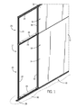
- FIG. 1 is a partial isometric view of a wall panel system of the present disclosure
- FIG. 2 is a section view of one section of the wall panel system
- FIG. 3 is a magnified view of the height adjustment mechanism of the present disclosure
- FIG. 4 is a section view taken along line 4 - 4 of FIG. 3 ;
- FIG. 5 is an isometric view of a bottom cross support rail that forms part of the wall panel system
- FIG. 6 is an end view of the bottom cross support rail shown in FIG. 5 ;
- FIG. 7 is a bottom isometric view of a top cross support rail
- FIG. 8 is an end view of the top cross support rail of FIG. 7 ;
- FIG. 9 is a magnified view taken along 9 - 9 of FIG. 8 ;
- FIG. 10 is a section view showing the attachment of a sliding door track to the top cross support rail.
- FIG. 11 is an exploded view showing the attachment of the sliding door track to the top cross support rail.
- FIG. 1 illustrates a wall panel system 10 constructed in accordance with the present disclosure.
- the wall panel system 10 shown in FIG. 1 includes a series of wall panels 12 positioned adjacent to each other to create multiple rooms and dividers within a building.
- Two of the wall panels 12 shown in FIG. 1 include a decorative outer tile 14 while the end wall panel 12 is shown with the decorative outer tile 14 removed.
- each of the wall panels 12 includes an upper panel section 16 and a lower panel section 18 that combine to form each of the individual wall panels 12 .
- the upper and lower panel sections 16 , 18 have generally a similar configuration and each include a support frame 20 .
- the upper and lower panel sections 16 , 18 are shown having different heights, the panel sections could be of the same height.
- each of the wall panels 12 could be formed as a single section including a single support frame.
- the support frame 20 of the lower panel section 18 includes a pair of spaced vertical uprights 22 that are connected to each other by a bottom cross support rail 24 and a top cross support rail 26 .
- the upper panel section 16 includes a similar support frame 20 that includes similar vertical uprights 22 , as well as the bottom cross support rail 24 and the top cross support rail 26 .
- Both the upper panel section 16 and the lower panel section 18 receive an outer decorative tile 14 on both the front and the back of the support frame 18 to provide the decorative, pleasing appearance for the wall panel 12 .
- the outer decorative tiles 14 could include fabric or another type of material to provide a visually pleasing appearance for the wall panel 12 .
- each wall panel 12 is received along a floor track 28 mounted to the floor 30 of a building.
- the floor track 28 is securely attached to the floor 30 and defines the configuration of the wall panel system 10 in a conventional manner.
- each wall panel 12 includes a height adjustment mechanism 32 that allows the height of the wall panel to be adjusted from the floor 30 .
- the adjustment mechanism 32 includes a support block 34 mounted within an open interior 36 of the bottom cross support rail 24 .
- the support block 34 includes a main body 38 including a guide base 39 and a pair of extending support flanges 40 . The configuration of the main body 38 and the support flanges 40 allows the support block 34 to slide along the length of the bottom support rail 24 and into a desired location.
- the height adjustment mechanism 32 further includes an adjustment rod 42 that includes an externally threaded outer surface 44 .
- the adjustment rod 42 includes an expanded head 46 located at a first end and an engagement portion 48 located at an opposite, second end.
- the externally threaded outer surface 44 of the adjustment rod 42 is received within an internally threaded bore 50 that extends through the main body 38 .
- the adjustment rod 42 extends through an access opening 52 formed in a top surface 55 of the bottom cross support rail 24 .
- an adjustment tool (not shown) can be used to rotate the adjustment rod 42 .
- the expanded head 46 is positioned beneath a bracket 54 which is supported on the floor track 28 .
- the bracket 54 includes a center opening 56 sized slightly larger than the outer diameter of the adjustment rod 42 such that the adjustment rod 42 is freely rotatable within the center opening 56 .
- the bracket 54 is secured to the floor track 28 by a series of connectors 58 .
- Each of the connectors 58 not only hold the bracket 54 in place along the floor track 28 , but also grips carpeting on the floor 30 to prevent movement of the bracket 54 along the length of the floor track 28 .
- the bottom cross support rail 24 includes a generally planar connecting wall 60 that is perpendicular to and extends between a pair of spaced sidewalls 62 .
- Each of the sidewalls 62 includes a recessed receiving slot 64 .
- the receiving slot 64 in the embodiment illustrated has a generally semicircular inner surface 66 and protrudes into the open interior 36 .
- Each of the sidewalls 62 includes a perpendicular support leg 68 that combine to define an access opening 70 for the open interior 36 . As described previously and shown in FIG.
- the top surface 55 includes an access opening 52 for the height adjustment mechanism at each end as well as a second, larger opening 72 that allows wires and cables to pass through the connecting wall 60 .
- the opening 72 is shown circular, the opening 72 could be rectangular and be formed as an elongated slot to provide additional clearance for wires and cables.
- each of the wall panels 12 includes a pair of height adjustment mechanisms 32 to support the weight of the wall panel 12 and adjust the height of the wall panel 12 from the floor 30 . Since each of the height adjustment mechanisms 32 can be adjusted separately, the orientation of the wall panel 12 can be adjusted to compensate for an uneven floor.
- each of the outer decorative tiles 14 include an attachment strip 74 located at each end of the outer decorative tile 14 .
- the attachment strip 74 includes an attachment feature 76 that includes a pair of flexible fingers 78 .
- the pair of flexible fingers 78 deflects to hold the attachment strip 74 and the associated outer decorative tile 14 in place within the receiving slot 64 on the bottom cross support rail 24 .
- the top cross support rail 26 includes a similar receiving slot 64 that receives the attachment feature 76 to hold the top end of the outer decorative tile 14 in place.
- a pair of cover members 80 are mounted to each side of the floor track 28 to provide a continuous, decorative appearance for the bottom end of the wall panel as the wall panel is vertically adjusted utilizing the height adjustment mechanism 32 .
- Each of the cover members 80 slides along the outer decorative tile 14 during the vertical movement of the wall panel 12 .
- the floor track 28 is securely held in place by a series of spaced connectors 82 that include a threaded shaft 84 that extend into the floor to hold the floor track 28 in place.
- the top cross support rail 26 is illustrated. Like the bottom cross support rail 24 shown in FIG. 5 , the top cross support rail 26 includes a connecting wall 60 that extends between a pair of sidewalls 62 that each include the receiving slot 64 . Each of the sidewalls 62 include an extending support leg 68 . However, unlike the bottom cross support rail 24 , each of the sidewalls 62 of the top cross support rail 26 includes an attachment rail 86 that extends along the entire length of the top cross support rail 26 from a first end 88 to a second end 90 . As illustrated in FIGS.
- the entire top cross support rail 26 is formed as a single, extruded member having the profile shown in FIG. 8 .
- both the bottom cross support rail 24 and the top cross support rail 26 are formed from an aluminum extrusion.
- other metallic materials are contemplated as being within the scope of the present disclosure.
- the attachment rail 86 includes an open attachment slot 92 that is defined between a first wall 94 and a second wall 96 .
- the first and second walls 94 , 96 are generally parallel to each other and define the width of the attachment slot 92 .
- the inner surface of each of the walls 94 , 96 includes a serrated surface 98 designed to receive a threaded connector.
- the wall panel 12 includes the upper panel section 16 and the lower panel section 18 stacked on top of each other. Specifically, the bottom cross support rail 24 of the upper panel section 16 rests on and is supported by the top cross support rail 26 of the lower panel section 18 .
- a panel splice strip 114 is connected between the upper panel section 16 and the lower panel section 18 to secure the two sections together.
- An identical splice strip 114 is included on the opposite side of the wall panel 12 .
- the splice strip is connected to the vertical uprights 22 by a series of connectors 116 .
- the splice strip 114 includes a center plate 118 that is aligned with the bottom cross support rail 24 and the top cross support rail 26 .
- each of the support rails 24 , 26 includes an end notch 120 that receives the center plate 118 .
- the panel splice strip 114 thus securely connects the upper panel section 16 to the lower panel section 18 and limits the lateral movement between the support rails 24 , 26 .
- the attachment slot 92 of the attachment rail 86 is accessible between the outer decorative tiles 14 of the upper and lower panel sections 16 , 18 .
- the attachment slot 92 provides a convenient point of attachment for different types of hanging devices, such as a bulletin board, message board, desk, bookshelf, or any other type of device that may be mounted to an inner surface of the wall panel 12 .
- top cross support rail 26 that forms part of the upper panel section 16 receives a ceiling track 100 in the opening between the support legs 68 .
- the receipt of the ceiling track 100 as illustrated further supports the wall panel 12 to restrict the wall panel 12 from tipping in its assembled condition.
- FIGS. 10 and 11 illustrate an additional feature of the wall panel and specifically the top cross support rail 26 including the attachment rail 86 .
- both of the outer decorative tiles 14 include an attachment strip 74 having the attachment structure 76 that holds the outer decorative tile within the receiving slot 64 .
- a sliding door track 102 is attached to the top cross support rails 26 by a series of connectors 104 that are each received within the attachment slot 92 defined by the attachment rail 86 .
- a threaded shaft 106 of the connector 104 is received within the attachment slot 92 and interacts with the serrated surface 98 formed on each of the walls 94 , 96 .
- the connector 104 passes through an opening 108 formed in the attachment flange 110 to support the door track 102 as illustrated.
- the door track 102 includes a roller slot 112 that receives and retains rollers of a sliding door (not shown). The rollers of the sliding door roll upon the contact surfaces 114 to allow the sliding door to move along the length of the door track 102 .
- the door track 102 is formed from an extruded aluminum material that provides the required strength and durability without excessive weight.
- the extruded bottom cross support rail 24 and the top cross support rail 26 have a generally similar configuration and are used to receive the height adjustment mechanism 32 , the door track 102 , and to form the attachment slot 92 between the upper panel section 16 and the lower panel section 18 .
Landscapes
- Engineering & Computer Science (AREA)
- Architecture (AREA)
- Civil Engineering (AREA)
- Structural Engineering (AREA)
- Physics & Mathematics (AREA)
- Electromagnetism (AREA)
- Wing Frames And Configurations (AREA)
- Finishing Walls (AREA)
Abstract
Description
Claims (11)
Priority Applications (3)
| Application Number | Priority Date | Filing Date | Title |
|---|---|---|---|
| US14/663,964 US9617732B2 (en) | 2015-03-20 | 2015-03-20 | Wall panel system |
| CA2892117A CA2892117C (en) | 2015-03-20 | 2015-05-20 | Wall panel system |
| CA2976565A CA2976565C (en) | 2015-03-20 | 2015-05-20 | Wall panel system |
Applications Claiming Priority (1)
| Application Number | Priority Date | Filing Date | Title |
|---|---|---|---|
| US14/663,964 US9617732B2 (en) | 2015-03-20 | 2015-03-20 | Wall panel system |
Publications (2)
| Publication Number | Publication Date |
|---|---|
| US20160273214A1 US20160273214A1 (en) | 2016-09-22 |
| US9617732B2 true US9617732B2 (en) | 2017-04-11 |
Family
ID=56924538
Family Applications (1)
| Application Number | Title | Priority Date | Filing Date |
|---|---|---|---|
| US14/663,964 Active US9617732B2 (en) | 2015-03-20 | 2015-03-20 | Wall panel system |
Country Status (2)
| Country | Link |
|---|---|
| US (1) | US9617732B2 (en) |
| CA (2) | CA2892117C (en) |
Cited By (6)
| Publication number | Priority date | Publication date | Assignee | Title |
|---|---|---|---|---|
| US20200056383A1 (en) * | 2018-02-01 | 2020-02-20 | Oldcastle Buildingenvelope, Inc. | Demountable wall system with removable cover |
| USD914916S1 (en) * | 2018-02-01 | 2021-03-30 | Oldcastle Buildingenvelope, Inc. | Face cover assembly |
| US20210172168A1 (en) * | 2010-05-05 | 2021-06-10 | Allsteel Inc. | Modular wall system |
| US20220243464A1 (en) * | 2019-06-20 | 2022-08-04 | Chung Jong Lee | Wall system with height adjustment unit |
| US11441313B2 (en) * | 2019-06-07 | 2022-09-13 | Knoll, Inc. | Enclosure assembly apparatus and method for forming same |
| USD1021151S1 (en) | 2021-04-26 | 2024-04-02 | Jaimes Industries, Inc. | Framing member |
Families Citing this family (7)
| Publication number | Priority date | Publication date | Assignee | Title |
|---|---|---|---|---|
| USD794826S1 (en) * | 2015-12-22 | 2017-08-15 | StadiArena Ltd | Stadium divider |
| US11795683B2 (en) * | 2019-12-16 | 2023-10-24 | Falkbuilt Ltd. | Drop-in ceiling wall system |
| US11926367B2 (en) * | 2021-02-12 | 2024-03-12 | The Shyft Group, Inc. | Bulkhead door bearing assembly |
| CN113006314B (en) * | 2021-03-03 | 2022-05-06 | 巨鑫建设集团有限公司 | Assembled energy-saving wall structure and assembly process thereof |
| KR102345056B1 (en) * | 2021-05-13 | 2021-12-29 | 노원훈 | Modular wall assembly using solenoid |
| CN115928978A (en) * | 2022-09-30 | 2023-04-07 | 广州康普顿至高建材有限公司 | A vertical segmented wall panel |
| CN116145862B (en) * | 2023-03-27 | 2025-10-31 | 福建思嘉新材料科技有限公司 | Marble-like texture interior wall with compression-resistant heat-insulating function |
Citations (35)
| Publication number | Priority date | Publication date | Assignee | Title |
|---|---|---|---|---|
| US3782048A (en) * | 1972-04-07 | 1974-01-01 | D Corman | Longitudinal support post |
| US4086734A (en) | 1976-08-11 | 1978-05-02 | Yoshida Kogyo K.K. | Adjustable-height baseboard for partitions |
| US4103463A (en) | 1976-09-28 | 1978-08-01 | Panelfold Doors, Inc. | Portable wall system |
| US4449337A (en) | 1982-03-15 | 1984-05-22 | Stow Davis Furniture Company | Adjustable base for office landscaping system |
| US4555880A (en) | 1982-03-15 | 1985-12-03 | Stow & Davis Furniture Company | Adjustable base for office landscaping system |
| US4596098A (en) * | 1985-05-09 | 1986-06-24 | Haworth, Inc. | Snap-fit raceway arrangement |
| US4631881A (en) * | 1985-04-30 | 1986-12-30 | Vickers Public Limited Company | Office screens and partitions |
| US4905428A (en) | 1988-11-16 | 1990-03-06 | Sykes Christopher C | Partition structures and frame elements therefor |
| US5042555A (en) | 1990-10-01 | 1991-08-27 | Modernfold, Inc. | Floor-supported movable wall panel with height adjustment system |
| US5309686A (en) | 1992-02-19 | 1994-05-10 | Kimball International, Inc. | Work space partition system |
| US5414967A (en) * | 1993-10-19 | 1995-05-16 | Unistrut International Corp. | Clean room wall system |
| US5524402A (en) * | 1988-11-16 | 1996-06-11 | Sykes; Christopher C. | Partition structures and frame elements therefor |
| US5881979A (en) | 1997-06-04 | 1999-03-16 | Knoll, Inc. | Telescoping leveler |
| US6000179A (en) | 1996-12-13 | 1999-12-14 | Steelcase Inc. | Stacking panel and off-module panel connections |
| US6141925A (en) | 1998-03-10 | 2000-11-07 | Steelcase Development Inc. | Clear wall panel system |
| US6266935B1 (en) | 1995-12-26 | 2001-07-31 | Steelcase Development Corporation | Floor channel for partition system |
| US6557310B2 (en) * | 2000-06-09 | 2003-05-06 | Smed International, Inc. | Interior space-dividing wall system |
| US20030089057A1 (en) * | 2001-06-15 | 2003-05-15 | Wiechecki Robert W. | Floor-to-ceiling wall panel system |
| US6651396B2 (en) | 1998-06-08 | 2003-11-25 | Haworth, Inc. | Wall panel system |
| US20030221384A1 (en) * | 2002-05-31 | 2003-12-04 | Burken David J. | Simplified wall panel |
| US20040020137A1 (en) * | 2002-02-15 | 2004-02-05 | Battey David J. | Customizable partition system |
| US6688056B2 (en) | 2000-12-22 | 2004-02-10 | Eberhard Von Huene & Associates | Moveable and demountable wall panel system |
| US6802171B2 (en) * | 2002-10-18 | 2004-10-12 | Mckinnon Duane | Framing member with fastener attachments having square threads |
| US6920727B2 (en) | 2001-02-14 | 2005-07-26 | Haworth, Inc. | Wall panel arrangement with accessory-supporting top cap |
| US7055287B2 (en) | 1996-08-05 | 2006-06-06 | Haworth, Inc. | Panel arrangement |
| US20060185250A1 (en) | 2005-02-01 | 2006-08-24 | Geoff Gosling | Integrated sliding door/panel system |
| US7150127B2 (en) | 2002-06-06 | 2006-12-19 | Kimball International, Inc. | Partition system |
| US20070283640A1 (en) * | 2006-06-09 | 2007-12-13 | Shivak Vincent A | Sliding door arrangement |
| US7543412B2 (en) | 2004-06-14 | 2009-06-09 | Haworth, Ltd. | Wall panel edge rail connector arrangement |
| US7814711B2 (en) | 2007-05-30 | 2010-10-19 | Tk Canada Limited | Interior wall system |
| US7861474B2 (en) | 2008-10-21 | 2011-01-04 | Haworth, Inc. | Ceiling attachment for full-height panel |
| US8015767B2 (en) | 2006-11-06 | 2011-09-13 | Haworth, Inc. | Connector arrangement for a wall panel system |
| US8024901B2 (en) | 2004-08-17 | 2011-09-27 | Dirtt Environmental Solutions Ltd. | Integrated reconfigurable wall system |
| US8151527B2 (en) | 2007-06-08 | 2012-04-10 | Dirtt Enviromental Solutions, Ltd. | System for providing both partial-height and full-height wall modules |
| US8272180B2 (en) | 2006-11-06 | 2012-09-25 | Haworth, Inc. | Structural top cap arrangement for wall panel |
-
2015
- 2015-03-20 US US14/663,964 patent/US9617732B2/en active Active
- 2015-05-20 CA CA2892117A patent/CA2892117C/en active Active
- 2015-05-20 CA CA2976565A patent/CA2976565C/en active Active
Patent Citations (37)
| Publication number | Priority date | Publication date | Assignee | Title |
|---|---|---|---|---|
| US3782048A (en) * | 1972-04-07 | 1974-01-01 | D Corman | Longitudinal support post |
| US4086734A (en) | 1976-08-11 | 1978-05-02 | Yoshida Kogyo K.K. | Adjustable-height baseboard for partitions |
| US4103463A (en) | 1976-09-28 | 1978-08-01 | Panelfold Doors, Inc. | Portable wall system |
| US4449337A (en) | 1982-03-15 | 1984-05-22 | Stow Davis Furniture Company | Adjustable base for office landscaping system |
| US4555880A (en) | 1982-03-15 | 1985-12-03 | Stow & Davis Furniture Company | Adjustable base for office landscaping system |
| US4631881A (en) * | 1985-04-30 | 1986-12-30 | Vickers Public Limited Company | Office screens and partitions |
| US4596098A (en) * | 1985-05-09 | 1986-06-24 | Haworth, Inc. | Snap-fit raceway arrangement |
| US5524402A (en) * | 1988-11-16 | 1996-06-11 | Sykes; Christopher C. | Partition structures and frame elements therefor |
| US4905428A (en) | 1988-11-16 | 1990-03-06 | Sykes Christopher C | Partition structures and frame elements therefor |
| US5042555A (en) | 1990-10-01 | 1991-08-27 | Modernfold, Inc. | Floor-supported movable wall panel with height adjustment system |
| US5309686A (en) | 1992-02-19 | 1994-05-10 | Kimball International, Inc. | Work space partition system |
| US5414967A (en) * | 1993-10-19 | 1995-05-16 | Unistrut International Corp. | Clean room wall system |
| US6266935B1 (en) | 1995-12-26 | 2001-07-31 | Steelcase Development Corporation | Floor channel for partition system |
| US7055287B2 (en) | 1996-08-05 | 2006-06-06 | Haworth, Inc. | Panel arrangement |
| US6000179A (en) | 1996-12-13 | 1999-12-14 | Steelcase Inc. | Stacking panel and off-module panel connections |
| US5881979A (en) | 1997-06-04 | 1999-03-16 | Knoll, Inc. | Telescoping leveler |
| US6141925A (en) | 1998-03-10 | 2000-11-07 | Steelcase Development Inc. | Clear wall panel system |
| US6651396B2 (en) | 1998-06-08 | 2003-11-25 | Haworth, Inc. | Wall panel system |
| US6557310B2 (en) * | 2000-06-09 | 2003-05-06 | Smed International, Inc. | Interior space-dividing wall system |
| US6688056B2 (en) | 2000-12-22 | 2004-02-10 | Eberhard Von Huene & Associates | Moveable and demountable wall panel system |
| US6920727B2 (en) | 2001-02-14 | 2005-07-26 | Haworth, Inc. | Wall panel arrangement with accessory-supporting top cap |
| US20030089057A1 (en) * | 2001-06-15 | 2003-05-15 | Wiechecki Robert W. | Floor-to-ceiling wall panel system |
| US20040020137A1 (en) * | 2002-02-15 | 2004-02-05 | Battey David J. | Customizable partition system |
| US20030221384A1 (en) * | 2002-05-31 | 2003-12-04 | Burken David J. | Simplified wall panel |
| US7150127B2 (en) | 2002-06-06 | 2006-12-19 | Kimball International, Inc. | Partition system |
| US7908805B2 (en) | 2002-06-06 | 2011-03-22 | Kimball International, Inc. | Partition system |
| US6802171B2 (en) * | 2002-10-18 | 2004-10-12 | Mckinnon Duane | Framing member with fastener attachments having square threads |
| US7543412B2 (en) | 2004-06-14 | 2009-06-09 | Haworth, Ltd. | Wall panel edge rail connector arrangement |
| US8024901B2 (en) | 2004-08-17 | 2011-09-27 | Dirtt Environmental Solutions Ltd. | Integrated reconfigurable wall system |
| US20060185250A1 (en) | 2005-02-01 | 2006-08-24 | Geoff Gosling | Integrated sliding door/panel system |
| US20070283640A1 (en) * | 2006-06-09 | 2007-12-13 | Shivak Vincent A | Sliding door arrangement |
| US7568311B2 (en) | 2006-06-09 | 2009-08-04 | Haworth, Inc. | Sliding door arrangement |
| US8015767B2 (en) | 2006-11-06 | 2011-09-13 | Haworth, Inc. | Connector arrangement for a wall panel system |
| US8272180B2 (en) | 2006-11-06 | 2012-09-25 | Haworth, Inc. | Structural top cap arrangement for wall panel |
| US7814711B2 (en) | 2007-05-30 | 2010-10-19 | Tk Canada Limited | Interior wall system |
| US8151527B2 (en) | 2007-06-08 | 2012-04-10 | Dirtt Enviromental Solutions, Ltd. | System for providing both partial-height and full-height wall modules |
| US7861474B2 (en) | 2008-10-21 | 2011-01-04 | Haworth, Inc. | Ceiling attachment for full-height panel |
Cited By (11)
| Publication number | Priority date | Publication date | Assignee | Title |
|---|---|---|---|---|
| US20210172168A1 (en) * | 2010-05-05 | 2021-06-10 | Allsteel Inc. | Modular wall system |
| US11725382B2 (en) | 2010-05-05 | 2023-08-15 | Allsteel Inc. | Modular wall system |
| US20200056383A1 (en) * | 2018-02-01 | 2020-02-20 | Oldcastle Buildingenvelope, Inc. | Demountable wall system with removable cover |
| US10669712B2 (en) | 2018-02-01 | 2020-06-02 | Oldcastle Buildingenvelope, Inc. | Demountable wall system and method |
| USD914916S1 (en) * | 2018-02-01 | 2021-03-30 | Oldcastle Buildingenvelope, Inc. | Face cover assembly |
| US11028579B2 (en) * | 2018-02-01 | 2021-06-08 | Oldcastle Buildingenvelope, Inc. | Demountable wall system with removable cover |
| US11441313B2 (en) * | 2019-06-07 | 2022-09-13 | Knoll, Inc. | Enclosure assembly apparatus and method for forming same |
| US11686089B2 (en) | 2019-06-07 | 2023-06-27 | Knoll, Inc. | Enclosure assembly apparatus and method for forming same |
| US20220243464A1 (en) * | 2019-06-20 | 2022-08-04 | Chung Jong Lee | Wall system with height adjustment unit |
| US11788283B2 (en) * | 2019-06-20 | 2023-10-17 | Chung Jong Lee | Wall system with height adjustment unit |
| USD1021151S1 (en) | 2021-04-26 | 2024-04-02 | Jaimes Industries, Inc. | Framing member |
Also Published As
| Publication number | Publication date |
|---|---|
| CA2976565A1 (en) | 2016-09-20 |
| US20160273214A1 (en) | 2016-09-22 |
| CA2976565C (en) | 2018-10-16 |
| CA2892117A1 (en) | 2016-09-20 |
| CA2892117C (en) | 2018-06-05 |
Similar Documents
| Publication | Publication Date | Title |
|---|---|---|
| US9617732B2 (en) | Wall panel system | |
| US6189268B1 (en) | Modular office furniture system | |
| US10508441B2 (en) | Demountable wall system | |
| US20150023729A1 (en) | Office furniture system | |
| US4263761A (en) | Portable acoustical panel system | |
| CA2804654C (en) | Demountable wall system | |
| US5517795A (en) | Furring stud assembly for slotted wall | |
| US8959859B2 (en) | Floor-to-ceiling partition wall assembly | |
| US6688056B2 (en) | Moveable and demountable wall panel system | |
| US7143562B2 (en) | Suspension system and structure for securing border ceiling panels | |
| US8402699B2 (en) | Sliding privacy door for partition systems | |
| US20140250633A1 (en) | Panel hardware system and associated methods | |
| US9920522B2 (en) | Demountable barrier system | |
| US9447579B2 (en) | Sliding door and pivoting door for demountable wall system | |
| US9010031B1 (en) | Modular medical headwall system | |
| US3702521A (en) | Closet construction | |
| CA2360142A1 (en) | Partition frame structure | |
| US9382710B1 (en) | Cubicle assembly | |
| JP6850692B2 (en) | Kamoi structure | |
| JP2020060049A (en) | Partition | |
| CA3027605C (en) | Demountable wall system | |
| IT201900016253A1 (en) | SYSTEM FOR THE PARTITION OF AN ENVIRONMENT | |
| JP3981762B2 (en) | Panel mounting angle adjustment structure for partition panels | |
| CA2841223C (en) | Sliding door and pivoting door for demountable wall system | |
| JP2002523658A (en) | Room splitting equipment for creating workspaces and offices |
Legal Events
| Date | Code | Title | Description |
|---|---|---|---|
| AS | Assignment |
Owner name: KRUEGER INTERNATIONAL, INC., WISCONSIN Free format text: ASSIGNMENT OF ASSIGNORS INTEREST;ASSIGNORS:KOPISH, ANDREW J.;WITTL, ROBERT M.;DART, MARK D.;AND OTHERS;SIGNING DATES FROM 20150320 TO 20150322;REEL/FRAME:035437/0142 |
|
| STCF | Information on status: patent grant |
Free format text: PATENTED CASE |
|
| AS | Assignment |
Owner name: WELLS FARGO BANK, N.A., WISCONSIN Free format text: SECURITY INTEREST;ASSIGNOR:KRUEGER INTERNATIONAL, INC.;REEL/FRAME:045694/0332 Effective date: 20180427 |
|
| MAFP | Maintenance fee payment |
Free format text: PAYMENT OF MAINTENANCE FEE, 4TH YEAR, LARGE ENTITY (ORIGINAL EVENT CODE: M1551); ENTITY STATUS OF PATENT OWNER: LARGE ENTITY Year of fee payment: 4 |
|
| AS | Assignment |
Owner name: JPMORGAN CHASE BANK, N.A., AS ADMINISTRATIVE AGENT, ILLINOIS Free format text: SECURITY INTEREST;ASSIGNOR:KRUEGER INTERNATIONAL, INC.;REEL/FRAME:060557/0320 Effective date: 20220630 |
|
| AS | Assignment |
Owner name: KRUEGER INTERNATIONAL, INC., WISCONSIN Free format text: RELEASE BY SECURED PARTY;ASSIGNOR:WELLS FARGO BANK, NATIONAL ASSOCIATION;REEL/FRAME:060651/0750 Effective date: 20220630 |
|
| MAFP | Maintenance fee payment |
Free format text: PAYMENT OF MAINTENANCE FEE, 8TH YEAR, LARGE ENTITY (ORIGINAL EVENT CODE: M1552); ENTITY STATUS OF PATENT OWNER: LARGE ENTITY Year of fee payment: 8 |