US9542525B2 - Additive smoothing of sharp concave edges on designed 3D printable polygonal mesh models - Google Patents
Additive smoothing of sharp concave edges on designed 3D printable polygonal mesh models Download PDFInfo
- Publication number
- US9542525B2 US9542525B2 US14/312,794 US201414312794A US9542525B2 US 9542525 B2 US9542525 B2 US 9542525B2 US 201414312794 A US201414312794 A US 201414312794A US 9542525 B2 US9542525 B2 US 9542525B2
- Authority
- US
- United States
- Prior art keywords
- medical device
- region
- interest
- design
- device design
- Prior art date
- Legal status (The legal status is an assumption and is not a legal conclusion. Google has not performed a legal analysis and makes no representation as to the accuracy of the status listed.)
- Expired - Fee Related, expires
Links
Images


Classifications
-
- G06F17/5086—
-
- G—PHYSICS
- G06—COMPUTING OR CALCULATING; COUNTING
- G06F—ELECTRIC DIGITAL DATA PROCESSING
- G06F30/00—Computer-aided design [CAD]
- G06F30/10—Geometric CAD
- G06F30/17—Mechanical parametric or variational design
-
- A—HUMAN NECESSITIES
- A61—MEDICAL OR VETERINARY SCIENCE; HYGIENE
- A61F—FILTERS IMPLANTABLE INTO BLOOD VESSELS; PROSTHESES; DEVICES PROVIDING PATENCY TO, OR PREVENTING COLLAPSING OF, TUBULAR STRUCTURES OF THE BODY, e.g. STENTS; ORTHOPAEDIC, NURSING OR CONTRACEPTIVE DEVICES; FOMENTATION; TREATMENT OR PROTECTION OF EYES OR EARS; BANDAGES, DRESSINGS OR ABSORBENT PADS; FIRST-AID KITS
- A61F2/00—Filters implantable into blood vessels; Prostheses, i.e. artificial substitutes or replacements for parts of the body; Appliances for connecting them with the body; Devices providing patency to, or preventing collapsing of, tubular structures of the body, e.g. stents
- A61F2/02—Prostheses implantable into the body
- A61F2/30—Joints
- A61F2/3094—Designing or manufacturing processes
- A61F2/30942—Designing or manufacturing processes for designing or making customized prostheses, e.g. using templates, CT or NMR scans, finite-element analysis or CAD-CAM techniques
-
- B—PERFORMING OPERATIONS; TRANSPORTING
- B33—ADDITIVE MANUFACTURING TECHNOLOGY
- B33Y—ADDITIVE MANUFACTURING, i.e. MANUFACTURING OF THREE-DIMENSIONAL [3-D] OBJECTS BY ADDITIVE DEPOSITION, ADDITIVE AGGLOMERATION OR ADDITIVE LAYERING, e.g. BY 3-D PRINTING, STEREOLITHOGRAPHY OR SELECTIVE LASER SINTERING
- B33Y50/00—Data acquisition or data processing for additive manufacturing
-
- G—PHYSICS
- G06—COMPUTING OR CALCULATING; COUNTING
- G06T—IMAGE DATA PROCESSING OR GENERATION, IN GENERAL
- G06T17/00—Three dimensional [3D] modelling, e.g. data description of 3D objects
- G06T17/20—Finite element generation, e.g. wire-frame surface description, tesselation
- G06T17/205—Re-meshing
-
- G—PHYSICS
- G06—COMPUTING OR CALCULATING; COUNTING
- G06T—IMAGE DATA PROCESSING OR GENERATION, IN GENERAL
- G06T19/00—Manipulating 3D models or images for computer graphics
- G06T19/20—Editing of 3D images, e.g. changing shapes or colours, aligning objects or positioning parts
-
- A—HUMAN NECESSITIES
- A61—MEDICAL OR VETERINARY SCIENCE; HYGIENE
- A61F—FILTERS IMPLANTABLE INTO BLOOD VESSELS; PROSTHESES; DEVICES PROVIDING PATENCY TO, OR PREVENTING COLLAPSING OF, TUBULAR STRUCTURES OF THE BODY, e.g. STENTS; ORTHOPAEDIC, NURSING OR CONTRACEPTIVE DEVICES; FOMENTATION; TREATMENT OR PROTECTION OF EYES OR EARS; BANDAGES, DRESSINGS OR ABSORBENT PADS; FIRST-AID KITS
- A61F2/00—Filters implantable into blood vessels; Prostheses, i.e. artificial substitutes or replacements for parts of the body; Appliances for connecting them with the body; Devices providing patency to, or preventing collapsing of, tubular structures of the body, e.g. stents
- A61F2/02—Prostheses implantable into the body
- A61F2/30—Joints
- A61F2002/30001—Additional features of subject-matter classified in A61F2/28, A61F2/30 and subgroups thereof
- A61F2002/30108—Shapes
- A61F2002/3011—Cross-sections or two-dimensional shapes
- A61F2002/30112—Rounded shapes, e.g. with rounded corners
-
- A—HUMAN NECESSITIES
- A61—MEDICAL OR VETERINARY SCIENCE; HYGIENE
- A61F—FILTERS IMPLANTABLE INTO BLOOD VESSELS; PROSTHESES; DEVICES PROVIDING PATENCY TO, OR PREVENTING COLLAPSING OF, TUBULAR STRUCTURES OF THE BODY, e.g. STENTS; ORTHOPAEDIC, NURSING OR CONTRACEPTIVE DEVICES; FOMENTATION; TREATMENT OR PROTECTION OF EYES OR EARS; BANDAGES, DRESSINGS OR ABSORBENT PADS; FIRST-AID KITS
- A61F2/00—Filters implantable into blood vessels; Prostheses, i.e. artificial substitutes or replacements for parts of the body; Appliances for connecting them with the body; Devices providing patency to, or preventing collapsing of, tubular structures of the body, e.g. stents
- A61F2/02—Prostheses implantable into the body
- A61F2/30—Joints
- A61F2/3094—Designing or manufacturing processes
- A61F2/30942—Designing or manufacturing processes for designing or making customized prostheses, e.g. using templates, CT or NMR scans, finite-element analysis or CAD-CAM techniques
- A61F2002/30948—Designing or manufacturing processes for designing or making customized prostheses, e.g. using templates, CT or NMR scans, finite-element analysis or CAD-CAM techniques using computerized tomography, i.e. CT scans
-
- A—HUMAN NECESSITIES
- A61—MEDICAL OR VETERINARY SCIENCE; HYGIENE
- A61F—FILTERS IMPLANTABLE INTO BLOOD VESSELS; PROSTHESES; DEVICES PROVIDING PATENCY TO, OR PREVENTING COLLAPSING OF, TUBULAR STRUCTURES OF THE BODY, e.g. STENTS; ORTHOPAEDIC, NURSING OR CONTRACEPTIVE DEVICES; FOMENTATION; TREATMENT OR PROTECTION OF EYES OR EARS; BANDAGES, DRESSINGS OR ABSORBENT PADS; FIRST-AID KITS
- A61F2/00—Filters implantable into blood vessels; Prostheses, i.e. artificial substitutes or replacements for parts of the body; Appliances for connecting them with the body; Devices providing patency to, or preventing collapsing of, tubular structures of the body, e.g. stents
- A61F2/02—Prostheses implantable into the body
- A61F2/30—Joints
- A61F2/3094—Designing or manufacturing processes
- A61F2/30942—Designing or manufacturing processes for designing or making customized prostheses, e.g. using templates, CT or NMR scans, finite-element analysis or CAD-CAM techniques
- A61F2002/30962—Designing or manufacturing processes for designing or making customized prostheses, e.g. using templates, CT or NMR scans, finite-element analysis or CAD-CAM techniques using stereolithography
-
- G—PHYSICS
- G06—COMPUTING OR CALCULATING; COUNTING
- G06T—IMAGE DATA PROCESSING OR GENERATION, IN GENERAL
- G06T2210/00—Indexing scheme for image generation or computer graphics
- G06T2210/41—Medical
-
- G—PHYSICS
- G06—COMPUTING OR CALCULATING; COUNTING
- G06T—IMAGE DATA PROCESSING OR GENERATION, IN GENERAL
- G06T2219/00—Indexing scheme for manipulating 3D models or images for computer graphics
- G06T2219/20—Indexing scheme for editing of 3D models
- G06T2219/2021—Shape modification
Definitions
- the present disclosure relates to polygon mesh models and, more specifically, to additive smoothing of sharp concave edges on designed 3D printable polygonal mesh models.
- Personalized medical devices are devices that have been custom-made to conform to the anatomy of a particular patient. Personalized medical devices may have a wide variety of uses and may be designed for use inside and outside the patient's body as tools, hardware, implants, prosthetics, etc.
- This technology is presently used in and has great potential to be used in medical fields such as orthopedics, dentistry, cardiology, audiology, podiatry, surgery, etc.
- the growing availability of 3D printers has made on-site fabrication of personalized medical devices more readily accessible.
- the process for fabricating personalized medical devices often includes a technician manually editing a computer aided design (CAD) of a medical device to conform to the anatomy of a particular patient. After the CAD has been so edited, it may be sent to a 3D printer, which may be able to quickly create the device in accordance with the edited design, without having to wait what could otherwise be weeks.
- CAD computer aided design
- a method for designing a personalized medical device includes receiving a template design of a medical device.
- An image including a patient anatomical geometry is acquired.
- the received template design of the medical device is combined with the acquired image including the patient anatomical geometry to create a custom medical device design.
- the combined image is displayed to a user.
- One or more seed points indicative of a location of a sharp concave edge present within the custom medical device design is received from a user.
- a region of interest encompassing the sharp concave edge is automatically identified within the custom medical device design using the one or more seed points received from the user.
- Surface smoothing of the custom medical device design is performed within the region of interest to bolster a thickness of the custom medical device design within the region of interest.
- a model is obtained from the surface smoothed custom medical device design.
- the received template design of the medical device may be a three-dimensional polygonal mesh model.
- the received template design of the medical device is a computer aided design (CAD) model.
- CAD computer aided design
- a computed tomography (CT) scanner may be used to acquire the image including the patient's anatomical geometry and the acquired image is a CT scan.
- CT computed tomography
- One or more Boolean operators may be used to combine the received template design of the medical device with the acquired image including the patient anatomical geometry.
- the user may provide two seed points indicative of the location of the sharp concave edge including a first seed point located on one side of the sharp concave edge and a second seed point located on an opposite side of the sharp concave edge.
- Automatically identifying the region of interest encompassing the sharp concave edge may include identifying shortest paths from the first seed point to a top and bottom boundary of the region of interest, identifying shortest paths from the second seed point to a top and bottom boundary of the region of interest, and identifying the region of interest as an area between the shortest paths of the first seed point and the shortest paths of the second seed point.
- the user may be provided with an opportunity to modify the region of interest either by adding/removing sections from the region of interest or by selecting one or more replacement seed points.
- Performing surface smoothing of the custom medical device design within the region of interest may include performing one or more mesh fairing techniques.
- Performing surface smoothing of the custom medical device design within the region of interest may include performing one or more edge blending techniques.
- Performing surface smoothing of the custom medical device design within the region of interest may include performing one or more sphere fitting techniques.
- Performing surface smoothing of the custom medical device design within the region of interest may include iteratively performing additive blending and sphere fitting.
- Performing surface smoothing of the custom medical device design within the region of interest may include performing inflation of concave vertices.
- Performing surface smoothing of the custom medical device design within the region of interest may include applying anisotropic discrete filter formulation that uses local principal curvature values to detect local sharp regions and utilizing a smoothing algorithm to apply different amounts of energy minimization to different local regions within the region of interest.
- Performing surface smoothing of the custom medical device design within the region of interest may include performing mean curvature flow-based smoothing to preserve local features.
- Performing surface smoothing of the custom medical device design within the region of interest may include applying bilateral filters to discrete surfaces of the custom medical device design to denoise surfaces thereof while preserving sharp features.
- the model obtained from the surface smoothed custom medical device design may be a 3D-printable mesh model.
- the model obtained from the surface smoothed custom medical device design may be 3D printed.
- a method for fabricating a personalized medical device includes receiving a template design of a medical device.
- An image including a patient anatomical geometry may be acquired.
- the received template design of the medical device is combined with the acquired image including the patient anatomical geometry to create a custom medical device design.
- a region of interest encompassing the sharp concave edge is identified within the custom medical device design using one or more seed points received from a user.
- Surface smoothing of the custom medical device design is performed within the region of interest to bolster a thickness of the custom medical device design within the region of interest.
- the surface-smoothed custom medical device design is 3D printed.
- a computer system includes a processor and a non-transitory, tangible, program storage medium, readable by the computer system, embodying a program of instructions executable by the processor to perform method steps for designing a personalized medical device.
- the method includes receiving a template design of a medical device. An image including a patient anatomical geometry is acquired. The received template design of the medical device is combined with the acquired image including the patient anatomical geometry to create a custom medical device design. A region of interest encompassing the sharp concave edge is identified within the custom medical device design using one or more seed points received from a user. Surface smoothing of the custom medical device design is performed within the region of interest to bolster a thickness of the custom medical device design within the region of interest.
- FIG. 1 is a diagram illustrating the combination of the acquired patient geometry and the designed model in accordance with exemplary embodiments of the present invention
- FIG. 2 is a flow chart illustrating an approach for creating personalized medical devices in accordance with exemplary embodiments of the present invention
- FIG. 3 is a schematic diagram illustrating a system for creating personalized medical devices in accordance with exemplary embodiments of the present invention
- FIGS. 4A-4D are graphical depictions illustrating a portion of a 3D polygonal model and an approach for identifying a sharp/concave edge section thereof in accordance with exemplary embodiments of the present invention.
- FIG. 5 shows an example of a computer system capable of implementing the method and apparatus according to embodiments of the present disclosure.
- Exemplary embodiment of the present invention seek to provide systems and methods for designing and manufacturing personalized medical devices.
- These personalized medical devices may be fabricated from CAD models, which may be 3D polygonal mesh models.
- a template model may be modified in accordance with the exact anatomical geometry of a patient and this modified model may then be fabricated using a 3D printer.
- the anatomical geometry of a patient may be acquired using a medical imaging device such as a computed tomography (CT) scanner, magnetic resonance imager (MRI), or from multiple 2D images acquired from different angles using a C-arm mounted x-ray device.
- a medical imaging device such as a computed tomography (CT) scanner, magnetic resonance imager (MRI), or from multiple 2D images acquired from different angles using a C-arm mounted x-ray device.
- CT computed tomography
- MRI magnetic resonance imager
- personalized medical devices may also be placed outside of the patient's body, for example, as a cast for setting a broken arm, imaging devices such as stereoscopic digital camera, 3D laser scanners, or the like may be used acquire 3D patient geometry.
- the anatomical geometry may thereafter be incorporated into a designed CAD model for the medical device being constructed. This combining may be performed using Boolean operations or other available means.
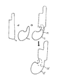
- FIG. 1 is a diagram illustrating the combination of the acquired patient geometry and the designed model in accordance with exemplary embodiments of the present invention.
- shape 11 represents the designed model.
- exemplary embodiments of the present invention contemplate the use of 3D shapes, and in particular, a 3D designed model
- the shapes of FIG. 1 are illustrated in 2D for the purpose of providing a simple and clear explanation and it is to be understood that, while this approach may indeed be performed with 2D shapes, exemplary embodiments of the present invention may be performed with 3D shapes.
- the designed model 11 may have a fairly regular shape with straight lines and deliberate curves. This stands in contrast to shape 12 , which represents a segment of anatomical geometry that has been acquired, for example, by way of obtaining a digital scan of the patient.
- shape 12 represents a segment of anatomical geometry that has been acquired, for example, by way of obtaining a digital scan of the patient.
- the anatomical geometry 12 may have a more irregular shape with many curves.
- the combined 3D polygonal mesh model represented as shape 13
- shape 13 may indeed have one or more sharp and/or concave edges, especially where the combination is performed using a Boolean operator.
- Area 14 highlights one such sharp/concave edge.
- Sharp and/or concave edges in medical devices may pose a number of challenges. For example, the structural integrity of the medical device, during fabrication or use, may be compromised. Indeed a sharp/concave edge may create a narrow section in the medical device that may act as a stress point during manufacturing and/or use and may lead to the device breaking apart at the stress point. This may be of particular concern during the process of 3D printing, in which the structure being fabricated may come under stress.
- Exemplary embodiments of the present invention seek to modify the combined 3D polygonal mesh model in such a way as to smooth out and bolster the sharp/concave edges thereof.
- smoothing of the shape may either lead to the increase or reduction of the device thickness at the site of the concavity
- exemplary embodiments of the present invention seek to increase the device thickness at these sections by adding additional material to the device as the region is smoothed. In this way, the device is said to be bolstered.
- the smoothed and bolstered 3D polygonal mesh model 13 ′ no longer appears vulnerable to cracking and breakage in area 14 ′.
- the 3D polygonal mesh model, so modified may then be 3D printed and utilized with a reduced risk of breakage.
- Exemplary embodiments of the present invention may use one or more mesh fairing techniques to smooth and bolster the sharp/concave regions.
- Mesh fairing may be preferable to edge blending techniques, which may also be used to smooth transitions, as edge blending may be less suitable for 3D polygonal models.
- edge blending techniques may be adapted for 3D polygonal models
- exemplary embodiments of the present invention may alternatively or additionally use edge blending techniques to smooth and bolster the sharp/concave regions.
- Mesh fairing techniques may be based on geometric flows. Such techniques may define mesh smoothing problems as an energy minimization problem such as curvature, gradient, surface area or volume.
- One example of a mesh fairing technique based on geometric flows is the Laplacian based smoothing algorithm. In its simplest formulation, Laplacian smoothing repositions vertices of the original mesh to the barycenter of their one ring neighbors. The integral of the sum of the maximal and minimal principal curvatures may be used as an energy minimization.
- a spring model may be used to minimize variation of curvature energy for generating a more blobby looking geometry.
- exemplary embodiments of the present invention may utilize an anisotropic discrete filter formulation that uses local principal curvature values to detect local sharp regions. Based on these detection results, the smoothing algorithm used may apply different amounts of minimization to different local regions. Mean curvature flow based smoothing may also be used to better preserve local features.
- mesh fairing techniques that may be used are spectral methods, which may be adapted from the image processing domain.
- bilateral filters may be applied to discrete surfaces of the mesh model to denoise surfaces while preserving sharp features.
- the efficient computation of eigenvectors of meshes with a number of vertices greater than a couple of thousand may be achieved by calculating a Fourier like transformation on meshes using Manifold Harmonic Basis functions and then applying band pass filtering on this transformation.
- mesh fairing techniques which provide a certain smoothness quality while minimizing different energy functions.
- Laplacian smoothing may be combined with optimization to increase mesh quality.
- Laplacian mesh optimization based on least square meshes where the smoothing is not applied iteratively, but rather is calculated in one step by solving a linear system of equations. This formulation may preserve Laplacian coordinates and introduce positional soft constraints to preserve local features.
- exemplary embodiments of the present invention may achieve mesh fairing or increased quality based on repositioning the vertices of the original object.
- FIG. 2 is a flow chart illustrating an approach for creating personalized medical devices in accordance with exemplary embodiments of the present invention.
- FIG. 3 is a schematic diagram illustrating a system for creating personalized medical devices in accordance with exemplary embodiments of the present invention. While the described approaches are framed with respect to creating personalize medical devices, it is to be understood that the techniques described herein for removing sharp/concave edges in polygonal mesh models may be applied more generally to a wide variety of uses.
- a computer aided design may be received (Step S 21 ).
- the CAD may represent a design for a medical device that is generic with respect to a particular patient.
- the CAD may be manually designed by a designer at a computer workstation 31 and stored in a database for subsequent use.
- the CAD may be a polygonal mesh model expressing a generic shape for the medical device.
- a patient may be scanned to acquire an anatomical geometry of the patient (Step S 22 ).
- a CT scanner may be used for this purpose.
- the received CAD and the patient's scan may be combined to produce a combined 3D polygonal mesh model representing an implementation of the medical device that has been customized for the particular patient's anatomical geometry (Step S 23 ).
- the combination of the CAD and the patient's scan may be performed using a graphics processing computer 33 that may be the same computer or a different computer from the computer workstation 31 used to generate the CAD file.
- FIGS. 4A-4C are graphical depictions illustrating a portion of a 3D polygonal model and an approach for identifying a sharp/concave edge section thereof in accordance with exemplary embodiments of the present invention. As can be seen in FIG. 4A , a user may identify two seed points, a first seed point P 1 located on one side of a concave edge region and a second seed point P 2 located on an opposite side of the concave edge region.
- shortest paths between the seed points and the boundaries may be automatically determined (shortest paths illustrated with arrows).
- shortest paths between the corresponding ends of the two shortest paths may be automatically determined (paths between corresponding ends illustrated with white lines).
- the region of the sharp/concave edge may be automatically identified (Step S 25 ) as the area within the shortest paths of FIG. 4B and the paths between corresponding ends of FIG. 4C (detected region illustrated with diagonal white lines).
- the region of interest representing the region in which the sharp/concave edge is found may be automatically identified (Step S 25 ) by path tracing and region growing, as discussed above. For example, as shown in FIGS. 4A-4D , paths are traced from the user selected points parallel to the edge and until sharp boundary edges are reached. The region of interest may then be filled-in between the traced paths and the sharp edges.
- a user may be prompted with the opportunity to edit the automatically identified region, for example, by adding or removing polygons or by re-initiating the region detection by editing one or both of the initial seed points.
- Surface smoothing may then be performed within the automatically identified area of interest (Step S 26 ).
- Surface smoothing may be performed using additive edge blending in accordance with exemplary embodiments of the present invention.
- additive edge blending the triangles labeled as the concave region may be modified using a combination of local sphere fitting and smoothing to the vertices in the region of interest.
- a vertex In performing local sphere fitting, a vertex may be modified such that it lies approximately on a sphere fitted to its local neighborhood.
- C represents the center of the sphere with a radius r
- N is the vertex normal
- P is the vertex position.
- the local sphere fitting problem may be solved by calculating the center and radius if the local sphere in a linear least square fashion.
- the three equations may be expressed for each vertex in the one ring neighborhood of each vertex and a sphere center and radius may be assigned to these vertices.
- This linear least square system may be illustrated as the following matrix A of size 3n ⁇ 4, where X is a 4 ⁇ 1 matrix and B is a 3n ⁇ 1 matrix (where n is a number of neighbors in one ring neighborhood):
- Smoothing may be used to create high quality transitions between the edge and adjacent regions.
- the following equation may be used to calculate smoothing force and final additive blending force:
- Additive blending may be used in addition to smoothing to remediate the sharp/concave edge within the region of interest.
- An additive blending tool used may be a combination of the local sphere fitting based inflation and vertex averaging based smoothing applied in an iterative manner.
- inflation may be applied to concave vertices such as those vertices which move along the outward normal direction during inflation.
- Two weights may be used to balance the amount of forces acting on each vertex.
- the weight w inflation may be used to control the amount of inflation to expand concave vertices.
- the other weight w smoothing may be used to control the effect of smoothing.
- the smoothed 3D polygon mesh model may be sent to a 3D printer 34 for 3D printing (Step S 27 ).
- Administration of the above steps may be performed with the use of a computer system.
- the computer system may permit
- FIG. 5 shows an example of a computer system which may implement a method and system of the present disclosure.
- the system and method of the present disclosure may be implemented in the form of a software application running on a computer system, for example, a mainframe, personal computer (PC), handheld computer, server, etc.
- the software application may be stored on a recording media locally accessible by the computer system and accessible via a hard wired or wireless connection to a network, for example, a local area network, or the Internet.
- the computer system referred to generally as system 1000 may include, for example, a central processing unit (CPU) 1001 , random access memory (RAM) 1004 , a printer interface 1010 , a display unit 1011 , a local area network (LAN) data transmission controller 1005 , a LAN interface 1006 , a network controller 1003 , an internal bus 1002 , and one or more input devices 1009 , for example, a keyboard, mouse etc.
- the system 1000 may be connected to a data storage device, for example, a hard disk, 1008 via a link 1007 .
Landscapes
- Engineering & Computer Science (AREA)
- Physics & Mathematics (AREA)
- Health & Medical Sciences (AREA)
- Theoretical Computer Science (AREA)
- Geometry (AREA)
- General Physics & Mathematics (AREA)
- Software Systems (AREA)
- Computer Graphics (AREA)
- Manufacturing & Machinery (AREA)
- Computer Hardware Design (AREA)
- General Engineering & Computer Science (AREA)
- Chemical & Material Sciences (AREA)
- Materials Engineering (AREA)
- Architecture (AREA)
- Cardiology (AREA)
- Biomedical Technology (AREA)
- Veterinary Medicine (AREA)
- Public Health (AREA)
- General Health & Medical Sciences (AREA)
- Orthopedic Medicine & Surgery (AREA)
- Animal Behavior & Ethology (AREA)
- Oral & Maxillofacial Surgery (AREA)
- Transplantation (AREA)
- Life Sciences & Earth Sciences (AREA)
- Heart & Thoracic Surgery (AREA)
- Vascular Medicine (AREA)
- Mathematical Optimization (AREA)
- Evolutionary Computation (AREA)
- Computational Mathematics (AREA)
- Pure & Applied Mathematics (AREA)
- Mathematical Analysis (AREA)
- Apparatus For Radiation Diagnosis (AREA)
Abstract
Description
P xi =C xlocalsphere +r×N xi
P yi =C ylocalsphere +r×N yi
P zi =C zlocalsphere ×r×N zi (1)
Here, C represents the center of the sphere with a radius r, N is the vertex normal and P is the vertex position.
v i n+1 w originalposition ×v i n +w sphere×(Center+(radius+μ)×N i) (3)
Inflation(v i)=(v i n+1 −v i n) (4)
F blend(v i)=w smoothing×Smooth(v i)+w inflation×Inflation(v i) (6)
Claims (20)
Priority Applications (5)
| Application Number | Priority Date | Filing Date | Title |
|---|---|---|---|
| US14/312,794 US9542525B2 (en) | 2014-06-24 | 2014-06-24 | Additive smoothing of sharp concave edges on designed 3D printable polygonal mesh models |
| CN201580034096.6A CN106471550B (en) | 2014-06-24 | 2015-06-19 | Additive smoothing of sharp concave edges of designed 3D printable polygon mesh models |
| DK15744733.5T DK3161800T3 (en) | 2014-06-24 | 2015-06-19 | Additive smoothing of sharp, concave edges on designed polygonal mesh models, which can be printed in 3D |
| EP15744733.5A EP3161800B1 (en) | 2014-06-24 | 2015-06-19 | Additive smoothing of sharp concave edges on designed 3d printable polygonal mesh models |
| PCT/US2015/036623 WO2015200114A1 (en) | 2014-06-24 | 2015-06-19 | Additive smoothing of sharp concave edges on designed 3d printable polygonal mesh models |
Applications Claiming Priority (1)
| Application Number | Priority Date | Filing Date | Title |
|---|---|---|---|
| US14/312,794 US9542525B2 (en) | 2014-06-24 | 2014-06-24 | Additive smoothing of sharp concave edges on designed 3D printable polygonal mesh models |
Publications (2)
| Publication Number | Publication Date |
|---|---|
| US20150370958A1 US20150370958A1 (en) | 2015-12-24 |
| US9542525B2 true US9542525B2 (en) | 2017-01-10 |
Family
ID=53762291
Family Applications (1)
| Application Number | Title | Priority Date | Filing Date |
|---|---|---|---|
| US14/312,794 Expired - Fee Related US9542525B2 (en) | 2014-06-24 | 2014-06-24 | Additive smoothing of sharp concave edges on designed 3D printable polygonal mesh models |
Country Status (5)
| Country | Link |
|---|---|
| US (1) | US9542525B2 (en) |
| EP (1) | EP3161800B1 (en) |
| CN (1) | CN106471550B (en) |
| DK (1) | DK3161800T3 (en) |
| WO (1) | WO2015200114A1 (en) |
Cited By (26)
| Publication number | Priority date | Publication date | Assignee | Title |
|---|---|---|---|---|
| US9849633B2 (en) * | 2014-06-23 | 2017-12-26 | Siemens Product Lifecycle Management Software Inc. | Removing sharp cusps from 3D shapes for additive manufacturing |
| US10537973B2 (en) | 2016-03-09 | 2020-01-21 | Applied Materials, Inc. | Correction of fabricated shapes in additive manufacturing |
| US10882160B2 (en) | 2017-05-25 | 2021-01-05 | Applied Materials, Inc. | Correction of fabricated shapes in additive manufacturing using sacrificial material |
| US10902944B1 (en) | 2020-01-06 | 2021-01-26 | Carlsmed, Inc. | Patient-specific medical procedures and devices, and associated systems and methods |
| US10967482B2 (en) | 2017-05-25 | 2021-04-06 | Applied Materials, Inc. | Fabrication of polishing pad by additive manufacturing onto mold |
| US11083586B2 (en) | 2017-12-04 | 2021-08-10 | Carlsmed, Inc. | Systems and methods for multi-planar orthopedic alignment |
| US11112770B2 (en) | 2017-11-09 | 2021-09-07 | Carlsmed, Inc. | Systems and methods for assisting a surgeon and producing patient-specific medical devices |
| US11166764B2 (en) | 2017-07-27 | 2021-11-09 | Carlsmed, Inc. | Systems and methods for assisting and augmenting surgical procedures |
| US11376076B2 (en) | 2020-01-06 | 2022-07-05 | Carlsmed, Inc. | Patient-specific medical systems, devices, and methods |
| USD958151S1 (en) | 2018-07-30 | 2022-07-19 | Carlsmed, Inc. | Display screen with a graphical user interface for surgical planning |
| US11432943B2 (en) | 2018-03-14 | 2022-09-06 | Carlsmed, Inc. | Systems and methods for orthopedic implant fixation |
| US11439514B2 (en) | 2018-04-16 | 2022-09-13 | Carlsmed, Inc. | Systems and methods for orthopedic implant fixation |
| US11443838B1 (en) | 2022-02-23 | 2022-09-13 | Carlsmed, Inc. | Non-fungible token systems and methods for storing and accessing healthcare data |
| US11696833B2 (en) | 2018-09-12 | 2023-07-11 | Carlsmed, Inc. | Systems and methods for orthopedic implants |
| US11793577B1 (en) | 2023-01-27 | 2023-10-24 | Carlsmed, Inc. | Techniques to map three-dimensional human anatomy data to two-dimensional human anatomy data |
| US11806241B1 (en) | 2022-09-22 | 2023-11-07 | Carlsmed, Inc. | System for manufacturing and pre-operative inspecting of patient-specific implants |
| US12127769B2 (en) | 2020-11-20 | 2024-10-29 | Carlsmed, Inc. | Patient-specific jig for personalized surgery |
| US12133803B2 (en) | 2018-11-29 | 2024-11-05 | Carlsmed, Inc. | Systems and methods for orthopedic implants |
| US12226315B2 (en) | 2020-08-06 | 2025-02-18 | Carlsmed, Inc. | Kinematic data-based patient-specific artificial discs, implants and associated systems and methods |
| US12232885B2 (en) | 2023-01-09 | 2025-02-25 | Carlsmed, Inc. | System for modeling patient spinal changes |
| US12232980B2 (en) | 2021-06-08 | 2025-02-25 | Carlsmed, Inc. | Patient-specific expandable spinal implants and associated systems and methods |
| US12274510B2 (en) | 2023-02-06 | 2025-04-15 | Carlsmed, Inc. | Patient-specific implant design and manufacturing system with a surgical implant positioning manager |
| US12390276B2 (en) | 2021-11-01 | 2025-08-19 | Carlsmed, Inc. | Spinal implants and surgical procedures with reduced subsidence, and associated systems and methods |
| US12491075B2 (en) | 2018-09-12 | 2025-12-09 | Carlsmed, Inc. | Systems and methods for designing orthopedic implants based on tissue characteristics |
| US12514644B1 (en) | 2025-01-09 | 2026-01-06 | Carlsmed, Inc. | Posterior fixation systems for spinal treatments |
| US12537081B2 (en) | 2021-08-31 | 2026-01-27 | Carlsmed, Inc. | Inter vertebral cage with integrated transmitter |
Families Citing this family (8)
| Publication number | Priority date | Publication date | Assignee | Title |
|---|---|---|---|---|
| KR102000486B1 (en) * | 2016-03-03 | 2019-07-17 | 한국전자통신연구원 | Apparatus and Method for Generating 3D Printing Model using Multiple Texture |
| CN110121735B (en) * | 2017-04-10 | 2023-12-15 | 西门子工业软件有限公司 | Identification and redesign of critically thin sections below 3D printer resolution |
| CN108629833A (en) * | 2018-05-07 | 2018-10-09 | 四川省有色冶金研究院有限公司 | A kind of structural optimization method of 3D printing model |
| US11325314B2 (en) * | 2018-12-19 | 2022-05-10 | 3D Systems, Inc. | Three-dimensional article manufacturing system with build plan optimization for high risk article design |
| CN110633511B (en) * | 2019-08-27 | 2023-05-09 | 广东工业大学 | Modularized design method and device for personalized medical instrument |
| WO2021118535A1 (en) | 2019-12-10 | 2021-06-17 | Hewlett-Packard Development Company, L.P. | Three-dimensional (3d) printed objects with fracture channels |
| CN111569296B (en) * | 2020-05-28 | 2022-01-04 | 东莞理工学院 | A kind of preparation method of personalized 3D printing protective face shield |
| WO2022032235A1 (en) | 2020-08-07 | 2022-02-10 | Ohio State Innovation Foundation | Systems and methods for point-of-need manufacturing |
Citations (5)
| Publication number | Priority date | Publication date | Assignee | Title |
|---|---|---|---|---|
| WO2003030787A1 (en) | 2001-10-05 | 2003-04-17 | Therics, Inc. | System and method for rapidly customizing design, manufacture and/or selection of biomedical devices |
| WO2004110309A2 (en) | 2003-06-11 | 2004-12-23 | Case Western Reserve University | Computer-aided-design of skeletal implants |
| WO2012027150A2 (en) | 2010-08-25 | 2012-03-01 | Siemens Corporation | Personalized orthopedic implant cad model generation |
| US20120209394A1 (en) | 1997-01-08 | 2012-08-16 | Conformis, Inc. | Patient-Adapted and Improved Articular Implants, Designs and Related Guide Tools |
| WO2013170872A1 (en) | 2012-05-14 | 2013-11-21 | Mobelife N.V. | Implantable bone augment and method for manufacturing an implantable bone augment |
Family Cites Families (6)
| Publication number | Priority date | Publication date | Assignee | Title |
|---|---|---|---|---|
| US7623127B2 (en) * | 2005-11-29 | 2009-11-24 | Siemens Medical Solutions Usa, Inc. | Method and apparatus for discrete mesh filleting and rounding through ball pivoting |
| US9504541B2 (en) * | 2006-01-05 | 2016-11-29 | Dentsply International Inc. | Method and system for designing custom restorations for dental implants |
| US8457930B2 (en) * | 2009-04-15 | 2013-06-04 | James Schroeder | Personalized fit and functional designed medical prostheses and surgical instruments and methods for making |
| GB2503358B (en) * | 2009-05-26 | 2014-02-12 | Rapiscan Systems Inc | X-ray tomographic inspection systems for the identification of specific target items |
| US10098761B2 (en) * | 2012-03-31 | 2018-10-16 | DePuy Synthes Products, Inc. | System and method for validating an orthopaedic surgical plan |
| CN103393486B (en) * | 2013-08-13 | 2015-09-02 | 华中科技大学同济医学院附属同济医院 | Method for preparing skull flap to be repaired by 3D printing |
-
2014
- 2014-06-24 US US14/312,794 patent/US9542525B2/en not_active Expired - Fee Related
-
2015
- 2015-06-19 CN CN201580034096.6A patent/CN106471550B/en not_active Expired - Fee Related
- 2015-06-19 WO PCT/US2015/036623 patent/WO2015200114A1/en not_active Ceased
- 2015-06-19 EP EP15744733.5A patent/EP3161800B1/en not_active Not-in-force
- 2015-06-19 DK DK15744733.5T patent/DK3161800T3/en active
Patent Citations (6)
| Publication number | Priority date | Publication date | Assignee | Title |
|---|---|---|---|---|
| US20120209394A1 (en) | 1997-01-08 | 2012-08-16 | Conformis, Inc. | Patient-Adapted and Improved Articular Implants, Designs and Related Guide Tools |
| WO2003030787A1 (en) | 2001-10-05 | 2003-04-17 | Therics, Inc. | System and method for rapidly customizing design, manufacture and/or selection of biomedical devices |
| WO2004110309A2 (en) | 2003-06-11 | 2004-12-23 | Case Western Reserve University | Computer-aided-design of skeletal implants |
| US20060094951A1 (en) * | 2003-06-11 | 2006-05-04 | David Dean | Computer-aided-design of skeletal implants |
| WO2012027150A2 (en) | 2010-08-25 | 2012-03-01 | Siemens Corporation | Personalized orthopedic implant cad model generation |
| WO2013170872A1 (en) | 2012-05-14 | 2013-11-21 | Mobelife N.V. | Implantable bone augment and method for manufacturing an implantable bone augment |
Non-Patent Citations (2)
| Title |
|---|
| Kronman Achia et al: "Image Segmentation Errors Correction by Mesh Segmentation and Deformation", Sep. 22, 2013 (Sep. 22, 2013), Advances in Communication Networking : 20th EUNICE/IFIP EG 6.2, 6.6 International Workshop, Rennes, France, Sep. 1-5, 2014, Revised Selected Papers; Lecture Notes in Computer Science , ISSN 1611-3349], Springer Verlag, DE, pp. 206-213, XP047042070; 2013. |
| PCT International Search Report mailed Oct. 13, 2015 for corresponding PCT Application No. PCT/US2015/036623 filed Jun. 19, 2015 (20 pages). |
Cited By (53)
| Publication number | Priority date | Publication date | Assignee | Title |
|---|---|---|---|---|
| US9849633B2 (en) * | 2014-06-23 | 2017-12-26 | Siemens Product Lifecycle Management Software Inc. | Removing sharp cusps from 3D shapes for additive manufacturing |
| US11154961B2 (en) | 2016-03-09 | 2021-10-26 | Applied Materials, Inc. | Correction of fabricated shapes in additive manufacturing |
| US10537973B2 (en) | 2016-03-09 | 2020-01-21 | Applied Materials, Inc. | Correction of fabricated shapes in additive manufacturing |
| US11597054B2 (en) | 2016-03-09 | 2023-03-07 | Applied Materials, Inc. | Correction of fabricated shapes in additive manufacturing |
| US10882160B2 (en) | 2017-05-25 | 2021-01-05 | Applied Materials, Inc. | Correction of fabricated shapes in additive manufacturing using sacrificial material |
| US11642757B2 (en) | 2017-05-25 | 2023-05-09 | Applied Materials, Inc. | Using sacrificial material in additive manufacturing of polishing pads |
| US10967482B2 (en) | 2017-05-25 | 2021-04-06 | Applied Materials, Inc. | Fabrication of polishing pad by additive manufacturing onto mold |
| US11059149B2 (en) | 2017-05-25 | 2021-07-13 | Applied Materials, Inc. | Correction of fabricated shapes in additive manufacturing using initial layer |
| US11084143B2 (en) | 2017-05-25 | 2021-08-10 | Applied Materials, Inc. | Correction of fabricated shapes in additive manufacturing using modified edge |
| US11166764B2 (en) | 2017-07-27 | 2021-11-09 | Carlsmed, Inc. | Systems and methods for assisting and augmenting surgical procedures |
| US12446966B2 (en) | 2017-07-27 | 2025-10-21 | Carlsmed, Inc. | Systems and methods for assisting and augmenting surgical procedures |
| US12514645B2 (en) | 2017-07-27 | 2026-01-06 | Carlsmed, Inc. | Systems and methods for assisting and augmenting surgical procedures |
| US12274506B2 (en) | 2017-07-27 | 2025-04-15 | Carlsmed, Inc. | Systems and methods for assisting and augmenting surgical procedures |
| US11857264B2 (en) | 2017-07-27 | 2024-01-02 | Carlsmed, Inc. | Systems and methods for physician designed surgical procedures |
| US11497559B1 (en) | 2017-07-27 | 2022-11-15 | Carlsmed, Inc. | Systems and methods for physician designed surgical procedures |
| US12274509B2 (en) | 2017-07-27 | 2025-04-15 | Carlsmed, Inc. | Systems and methods for physician designed surgical procedures |
| US11112770B2 (en) | 2017-11-09 | 2021-09-07 | Carlsmed, Inc. | Systems and methods for assisting a surgeon and producing patient-specific medical devices |
| US12530015B2 (en) | 2017-11-09 | 2026-01-20 | Carlsmed, Inc. | Systems and methods for assisting a surgeon and producing patient-specific medical devices |
| US11083586B2 (en) | 2017-12-04 | 2021-08-10 | Carlsmed, Inc. | Systems and methods for multi-planar orthopedic alignment |
| US12427025B2 (en) | 2017-12-04 | 2025-09-30 | Carlsmed, Inc. | Systems and methods for multi-planar orthopedic alignment |
| US11432943B2 (en) | 2018-03-14 | 2022-09-06 | Carlsmed, Inc. | Systems and methods for orthopedic implant fixation |
| US12491085B2 (en) | 2018-03-14 | 2025-12-09 | Carlsmed, Inc. | Systems and methods for orthopedic implant fixation |
| US11439514B2 (en) | 2018-04-16 | 2022-09-13 | Carlsmed, Inc. | Systems and methods for orthopedic implant fixation |
| US12245952B2 (en) | 2018-04-16 | 2025-03-11 | Carlsmed, Inc. | Systems and methods for orthopedic implant fixation |
| US12251320B2 (en) | 2018-04-16 | 2025-03-18 | Carlsmed, Inc. | Systems and methods for orthopedic implant fixation |
| USD958151S1 (en) | 2018-07-30 | 2022-07-19 | Carlsmed, Inc. | Display screen with a graphical user interface for surgical planning |
| US11717412B2 (en) | 2018-09-12 | 2023-08-08 | Carlsmed, Inc. | Systems and methods for orthopedic implants |
| US11696833B2 (en) | 2018-09-12 | 2023-07-11 | Carlsmed, Inc. | Systems and methods for orthopedic implants |
| US12491075B2 (en) | 2018-09-12 | 2025-12-09 | Carlsmed, Inc. | Systems and methods for designing orthopedic implants based on tissue characteristics |
| US12251313B2 (en) | 2018-09-12 | 2025-03-18 | Carlsmed, Inc. | Systems and methods for orthopedic implants |
| US12274622B2 (en) | 2018-11-29 | 2025-04-15 | Carlsmed, Inc. | Systems and methods for orthopedic implants |
| US12133803B2 (en) | 2018-11-29 | 2024-11-05 | Carlsmed, Inc. | Systems and methods for orthopedic implants |
| US12376907B2 (en) | 2020-01-06 | 2025-08-05 | Carlsmed, Inc. | Patient-specific medical systems, devices, and methods |
| US12137983B2 (en) | 2020-01-06 | 2024-11-12 | Carlsmed, Inc. | Patient-specific medical systems, devices, and methods |
| US10902944B1 (en) | 2020-01-06 | 2021-01-26 | Carlsmed, Inc. | Patient-specific medical procedures and devices, and associated systems and methods |
| US11376076B2 (en) | 2020-01-06 | 2022-07-05 | Carlsmed, Inc. | Patient-specific medical systems, devices, and methods |
| US11678938B2 (en) | 2020-01-06 | 2023-06-20 | Carlsmed, Inc. | Patient-specific medical systems, devices, and methods |
| US11854683B2 (en) | 2020-01-06 | 2023-12-26 | Carlsmed, Inc. | Patient-specific medical procedures and devices, and associated systems and methods |
| US12226315B2 (en) | 2020-08-06 | 2025-02-18 | Carlsmed, Inc. | Kinematic data-based patient-specific artificial discs, implants and associated systems and methods |
| US12127769B2 (en) | 2020-11-20 | 2024-10-29 | Carlsmed, Inc. | Patient-specific jig for personalized surgery |
| US12232980B2 (en) | 2021-06-08 | 2025-02-25 | Carlsmed, Inc. | Patient-specific expandable spinal implants and associated systems and methods |
| US12537081B2 (en) | 2021-08-31 | 2026-01-27 | Carlsmed, Inc. | Inter vertebral cage with integrated transmitter |
| US12390276B2 (en) | 2021-11-01 | 2025-08-19 | Carlsmed, Inc. | Spinal implants and surgical procedures with reduced subsidence, and associated systems and methods |
| US11984205B2 (en) | 2022-02-23 | 2024-05-14 | Carlsmed, Inc. | Non-fungible token systems and methods for storing and accessing healthcare data |
| US11443838B1 (en) | 2022-02-23 | 2022-09-13 | Carlsmed, Inc. | Non-fungible token systems and methods for storing and accessing healthcare data |
| US12537082B2 (en) | 2022-02-23 | 2026-01-27 | Carlsmed, Inc. | Non-fungible token systems and methods for storing and accessing healthcare data |
| US12142357B2 (en) | 2022-02-23 | 2024-11-12 | Carlsmed, Inc. | Non-fungible token systems and methods for storing and accessing healthcare data |
| US11806241B1 (en) | 2022-09-22 | 2023-11-07 | Carlsmed, Inc. | System for manufacturing and pre-operative inspecting of patient-specific implants |
| US12533238B2 (en) | 2022-09-22 | 2026-01-27 | Carlsmed, Inc. | System for manufacturing and pre-operative inspecting of patient-specific implants |
| US12232885B2 (en) | 2023-01-09 | 2025-02-25 | Carlsmed, Inc. | System for modeling patient spinal changes |
| US11793577B1 (en) | 2023-01-27 | 2023-10-24 | Carlsmed, Inc. | Techniques to map three-dimensional human anatomy data to two-dimensional human anatomy data |
| US12274510B2 (en) | 2023-02-06 | 2025-04-15 | Carlsmed, Inc. | Patient-specific implant design and manufacturing system with a surgical implant positioning manager |
| US12514644B1 (en) | 2025-01-09 | 2026-01-06 | Carlsmed, Inc. | Posterior fixation systems for spinal treatments |
Also Published As
| Publication number | Publication date |
|---|---|
| EP3161800A1 (en) | 2017-05-03 |
| CN106471550B (en) | 2019-08-30 |
| US20150370958A1 (en) | 2015-12-24 |
| DK3161800T3 (en) | 2019-03-11 |
| CN106471550A (en) | 2017-03-01 |
| EP3161800B1 (en) | 2018-11-21 |
| WO2015200114A1 (en) | 2015-12-30 |
Similar Documents
| Publication | Publication Date | Title |
|---|---|---|
| US9542525B2 (en) | Additive smoothing of sharp concave edges on designed 3D printable polygonal mesh models | |
| EP3158537B1 (en) | Removing sharp cusps from 3d shapes for additive manufacturing | |
| EP3624726B1 (en) | Automatic alignment and orientation of digital 3d dental arch pairs | |
| JP4799010B2 (en) | Tomography 3D display filter processing method for patient and medical tomography system | |
| KR101105494B1 (en) | Patient-specific 3D human bone model reconstruction method | |
| CN105608728A (en) | Semantic medical image to 3D print of anatomic structure | |
| US10770175B2 (en) | System and method for segmentation and visualization of medical image data | |
| WO2009132340A1 (en) | Analysis of anatomic regions delineated from image data | |
| EP3711016B1 (en) | Systems and methods for segmenting images | |
| US20220375099A1 (en) | Segmentating a medical image | |
| WO2015010745A1 (en) | Multi-modal segmentation of image data | |
| KR20200056764A (en) | Method for automatically set up joints to create facial animation of 3d face model and computer program | |
| US11227415B2 (en) | Method for creating a composite cephalometric image | |
| JP6383182B2 (en) | Image processing apparatus, image processing system, image processing method, and program | |
| CN111369662B (en) | Method and system for reconstructing three-dimensional model of blood vessels in CT images | |
| Chan et al. | Quantifying normal geometric variation in human pulmonary lobar geometry from high resolution computed tomography | |
| CN106663339A (en) | Device for visualizing a 3d object | |
| CN105427283B (en) | A kind of interactive body dividing method based on Hessian implicit functions | |
| Marin et al. | Automatic contour detection from dental CBCT DICOM data | |
| Zhang et al. | An effective approach of teeth segmentation within the 3d cone beam computed tomography image based on deformable surface model | |
| KR102733517B1 (en) | Method for creating of 3d guide modeling file of implant placement guide | |
| JP7462188B2 (en) | Medical image processing device, medical image processing method, and program | |
| Amirhossein et al. | Automatic Pipeline to Generate Hexahedral Meshes With Layer-Specific Smoothing From Biomedical Images for Finite Element Modeling | |
| JP6790928B2 (en) | Image processing device | |
| Kallemeyn et al. | Hexahedral meshing of subject-specific anatomic structures using mapped building blocks |
Legal Events
| Date | Code | Title | Description |
|---|---|---|---|
| AS | Assignment |
Owner name: SIEMENS CORPORATION, NEW JERSEY Free format text: ASSIGNMENT OF ASSIGNORS INTEREST;ASSIGNORS:ARISOY, ERHAN;DALLORO, LIVIO;MUSUVATHY, SURAJ RAVI;SIGNING DATES FROM 20140711 TO 20140714;REEL/FRAME:033423/0420 |
|
| AS | Assignment |
Owner name: SIEMENS PRODUCT LIFECYCLE MANAGEMENT SOFTWARE INC. Free format text: ASSIGNMENT OF ASSIGNORS INTEREST;ASSIGNOR:SIEMENS CORPORATION;REEL/FRAME:033591/0737 Effective date: 20140813 |
|
| STCF | Information on status: patent grant |
Free format text: PATENTED CASE |
|
| AS | Assignment |
Owner name: SIEMENS INDUSTRY SOFTWARE INC., TEXAS Free format text: CHANGE OF NAME;ASSIGNOR:SIEMENS PRODUCT LIFECYCLE MANAGEMENT SOFTWARE INC.;REEL/FRAME:051171/0024 Effective date: 20191021 |
|
| MAFP | Maintenance fee payment |
Free format text: PAYMENT OF MAINTENANCE FEE, 4TH YEAR, LARGE ENTITY (ORIGINAL EVENT CODE: M1551); ENTITY STATUS OF PATENT OWNER: LARGE ENTITY Year of fee payment: 4 |
|
| FEPP | Fee payment procedure |
Free format text: MAINTENANCE FEE REMINDER MAILED (ORIGINAL EVENT CODE: REM.); ENTITY STATUS OF PATENT OWNER: LARGE ENTITY |
|
| LAPS | Lapse for failure to pay maintenance fees |
Free format text: PATENT EXPIRED FOR FAILURE TO PAY MAINTENANCE FEES (ORIGINAL EVENT CODE: EXP.); ENTITY STATUS OF PATENT OWNER: LARGE ENTITY |
|
| STCH | Information on status: patent discontinuation |
Free format text: PATENT EXPIRED DUE TO NONPAYMENT OF MAINTENANCE FEES UNDER 37 CFR 1.362 |
|
| FP | Lapsed due to failure to pay maintenance fee |
Effective date: 20250110 |