US9541299B2 - Setting-independent climate regulator control - Google Patents
Setting-independent climate regulator control Download PDFInfo
- Publication number
- US9541299B2 US9541299B2 US13/714,714 US201213714714A US9541299B2 US 9541299 B2 US9541299 B2 US 9541299B2 US 201213714714 A US201213714714 A US 201213714714A US 9541299 B2 US9541299 B2 US 9541299B2
- Authority
- US
- United States
- Prior art keywords
- climate
- regulator
- target
- climate regulator
- setting
- Prior art date
- Legal status (The legal status is an assumption and is not a legal conclusion. Google has not performed a legal analysis and makes no representation as to the accuracy of the status listed.)
- Active, expires
Links
- 238000000034 method Methods 0.000 claims abstract description 48
- 238000013507 mapping Methods 0.000 claims description 48
- 230000004044 response Effects 0.000 claims description 6
- 230000008859 change Effects 0.000 claims description 3
- 108010001267 Protein Subunits Proteins 0.000 abstract description 2
- 230000007175 bidirectional communication Effects 0.000 abstract description 2
- 230000007246 mechanism Effects 0.000 abstract description 2
- 238000001816 cooling Methods 0.000 description 25
- 230000001105 regulatory effect Effects 0.000 description 11
- 230000006854 communication Effects 0.000 description 9
- 238000004891 communication Methods 0.000 description 9
- 230000008901 benefit Effects 0.000 description 8
- 230000003287 optical effect Effects 0.000 description 6
- 239000013618 particulate matter Substances 0.000 description 5
- 230000006870 function Effects 0.000 description 4
- 239000007788 liquid Substances 0.000 description 4
- 238000010586 diagram Methods 0.000 description 3
- 238000005516 engineering process Methods 0.000 description 3
- 238000012986 modification Methods 0.000 description 3
- 230000004048 modification Effects 0.000 description 3
- 230000004075 alteration Effects 0.000 description 2
- 238000003491 array Methods 0.000 description 2
- 239000000356 contaminant Substances 0.000 description 2
- 230000001276 controlling effect Effects 0.000 description 2
- 238000013461 design Methods 0.000 description 2
- 238000001514 detection method Methods 0.000 description 2
- 230000003292 diminished effect Effects 0.000 description 2
- 230000000694 effects Effects 0.000 description 2
- 230000005686 electrostatic field Effects 0.000 description 2
- 238000001914 filtration Methods 0.000 description 2
- 238000010438 heat treatment Methods 0.000 description 2
- 238000004519 manufacturing process Methods 0.000 description 2
- 239000002245 particle Substances 0.000 description 2
- 230000008569 process Effects 0.000 description 2
- 239000004065 semiconductor Substances 0.000 description 2
- 230000003068 static effect Effects 0.000 description 2
- 230000004913 activation Effects 0.000 description 1
- 238000004378 air conditioning Methods 0.000 description 1
- QVGXLLKOCUKJST-UHFFFAOYSA-N atomic oxygen Chemical compound [O] QVGXLLKOCUKJST-UHFFFAOYSA-N 0.000 description 1
- 230000001413 cellular effect Effects 0.000 description 1
- 238000004590 computer program Methods 0.000 description 1
- 238000011109 contamination Methods 0.000 description 1
- 230000001419 dependent effect Effects 0.000 description 1
- 239000000428 dust Substances 0.000 description 1
- 230000005611 electricity Effects 0.000 description 1
- 238000004134 energy conservation Methods 0.000 description 1
- 230000001747 exhibiting effect Effects 0.000 description 1
- 230000008713 feedback mechanism Effects 0.000 description 1
- 239000000835 fiber Substances 0.000 description 1
- 238000011010 flushing procedure Methods 0.000 description 1
- 239000007789 gas Substances 0.000 description 1
- 239000000463 material Substances 0.000 description 1
- 229910052751 metal Inorganic materials 0.000 description 1
- 239000002184 metal Substances 0.000 description 1
- 150000002739 metals Chemical class 0.000 description 1
- 239000000203 mixture Substances 0.000 description 1
- 238000012544 monitoring process Methods 0.000 description 1
- 230000006855 networking Effects 0.000 description 1
- 239000001301 oxygen Substances 0.000 description 1
- 229910052760 oxygen Inorganic materials 0.000 description 1
- 230000002093 peripheral effect Effects 0.000 description 1
- 230000002085 persistent effect Effects 0.000 description 1
- 238000012545 processing Methods 0.000 description 1
- 230000000644 propagated effect Effects 0.000 description 1
- 230000009467 reduction Effects 0.000 description 1
- 239000000779 smoke Substances 0.000 description 1
- 239000007787 solid Substances 0.000 description 1
- 239000000126 substance Substances 0.000 description 1
- 230000001502 supplementing effect Effects 0.000 description 1
- 230000001360 synchronised effect Effects 0.000 description 1
- 230000002195 synergetic effect Effects 0.000 description 1
- 230000008685 targeting Effects 0.000 description 1
- 230000003685 thermal hair damage Effects 0.000 description 1
- 238000012876 topography Methods 0.000 description 1
- 238000013519 translation Methods 0.000 description 1
Images


Classifications
-
- F—MECHANICAL ENGINEERING; LIGHTING; HEATING; WEAPONS; BLASTING
- F24—HEATING; RANGES; VENTILATING
- F24F—AIR-CONDITIONING; AIR-HUMIDIFICATION; VENTILATION; USE OF AIR CURRENTS FOR SCREENING
- F24F11/00—Control or safety arrangements
- F24F11/70—Control systems characterised by their outputs; Constructional details thereof
- F24F11/72—Control systems characterised by their outputs; Constructional details thereof for controlling the supply of treated air, e.g. its pressure
- F24F11/74—Control systems characterised by their outputs; Constructional details thereof for controlling the supply of treated air, e.g. its pressure for controlling air flow rate or air velocity
- F24F11/77—Control systems characterised by their outputs; Constructional details thereof for controlling the supply of treated air, e.g. its pressure for controlling air flow rate or air velocity by controlling the speed of ventilators
-
- F24F11/0079—
-
- H—ELECTRICITY
- H05—ELECTRIC TECHNIQUES NOT OTHERWISE PROVIDED FOR
- H05K—PRINTED CIRCUITS; CASINGS OR CONSTRUCTIONAL DETAILS OF ELECTRIC APPARATUS; MANUFACTURE OF ASSEMBLAGES OF ELECTRICAL COMPONENTS
- H05K7/00—Constructional details common to different types of electric apparatus
- H05K7/20—Modifications to facilitate cooling, ventilating, or heating
- H05K7/20709—Modifications to facilitate cooling, ventilating, or heating for server racks or cabinets; for data centers, e.g. 19-inch computer racks
- H05K7/20836—Thermal management, e.g. server temperature control
-
- F—MECHANICAL ENGINEERING; LIGHTING; HEATING; WEAPONS; BLASTING
- F24—HEATING; RANGES; VENTILATING
- F24F—AIR-CONDITIONING; AIR-HUMIDIFICATION; VENTILATION; USE OF AIR CURRENTS FOR SCREENING
- F24F11/00—Control or safety arrangements
- F24F11/62—Control or safety arrangements characterised by the type of control or by internal processing, e.g. using fuzzy logic, adaptive control or estimation of values
- F24F11/63—Electronic processing
- F24F11/64—Electronic processing using pre-stored data
-
- F24F2011/0063—
-
- Y—GENERAL TAGGING OF NEW TECHNOLOGICAL DEVELOPMENTS; GENERAL TAGGING OF CROSS-SECTIONAL TECHNOLOGIES SPANNING OVER SEVERAL SECTIONS OF THE IPC; TECHNICAL SUBJECTS COVERED BY FORMER USPC CROSS-REFERENCE ART COLLECTIONS [XRACs] AND DIGESTS
- Y02—TECHNOLOGIES OR APPLICATIONS FOR MITIGATION OR ADAPTATION AGAINST CLIMATE CHANGE
- Y02B—CLIMATE CHANGE MITIGATION TECHNOLOGIES RELATED TO BUILDINGS, e.g. HOUSING, HOUSE APPLIANCES OR RELATED END-USER APPLICATIONS
- Y02B30/00—Energy efficient heating, ventilation or air conditioning [HVAC]
- Y02B30/70—Efficient control or regulation technologies, e.g. for control of refrigerant flow, motor or heating
-
- Y02B30/746—
Definitions
- a computational unit such as a cabinet for a computer comprising a set of electronic components (e.g., processors, memory components, and nonvolatile storage devices), where climate regulation within the enclosure is achieved through the use of one or more climate regulators.
- the enclosure may comprise thermal climate regulators, such as a set of fans positioned and configured to draw air into the enclosure, push the air over the components of the computational unit, and expel heated air out of the enclosure as exhaust. More powerful temperature regulation may be achieved through the use of heating components and/or air conditioning components that actively heat or cool the inlet air or the residual air within the enclosure.
- climate regulators may manage other climate properties of the enclosure (e.g., humidity regulators may add or remove moisture from the inlet air; air pressure regulators may adjust the air pressure within the enclosure; and air filter regulators may remove particulate contaminants of inlet air).
- active climate regulators may interoperate with “passive” climate regulators (e.g., heatsinks that physically contact the electronic components and diffuse heat over a large area surface) to regulate the climate within the enclosure.
- climate regulators provided within an enclosure may present configurable operating settings. For example, fans may be set to operate at faster or slower fan speeds to achieve variable cooling, and a fan array may adjust the number of operating fans. While more powerful climate regulation may be desirable to maintain the climate within the enclosure within a precise range, higher operating rates of climate regulators may involve greater energy expenditure (e.g., higher electricity costs and faster drain of batteries of portable devices) and/or increased noise or vibration within the enclosure. Accordingly, the operating settings of climate regulators may be adjusted by a user and/or automatically by the enclosure.
- a computational unit utilizes a climate regulator device by choosing among the available climate regulator settings.
- a fan array may specify a set of fan settings to the computational unit, and the computational unit may select a desired setting and operate the fan at the selected setting.
- the fan array may specify the capabilities associated with each setting (e.g., the rate of cooling or target temperature achievable by a particular setting) in order to enable the computational unit to provide a more accurate selection.
- a climate regulator device may specify its settings in a manner that the computational unit is unable to utilize (e.g., the computational unit may operate on degrees Celsius, and a fan array may specify climate regulation in degrees Fahrenheit).
- a new climate regulating technology may provide a different type of setting that the computational unit does not understand or support (e.g., a water-cooled thermal flushing system may report its cooling settings as a flow rate achievable by the pump).
- such architectures involve a bidirectional communication architecture between the climate regulator device and the computational unit (e.g., the climate regulator device reporting its settings to the computational unit, and the computational unit informing the climate regulator device of its selection), wherein the complexity of the climate regulation infrastructure may be reduced without diminished functionality.
- such architecture may provide limited management support, such as reconciling conflicting requests from two or more computational sub-units; applying a request to two or more climate regulator devices; or recovering from failures in the climate regulation infrastructure.
- the computational unit may specify a climate target that is independent of the climate regulator settings of the climate regulator device, such as an arbitrary climate regulation gradient specified on a scale of 0 to 100, wherein 0 indicates minimum climate regulation (e.g., no climate regulation) and 100 indicates maximum climate regulation.
- a climate regulator controller may receive the climate target from the computational unit, and may map the climate target into a selection of a setting among the settings supported by the particular climate regulator device(s) provided in the enclosure.
- Such architectures dissociate the requests issued by the computational unit from the particular settings and capabilities of the climate regulator device, thus avoiding the communication of the capabilities to the computational unit and the specification of the climate target as a setting of the climate regulator device.
- Such architectures may also enable the translation of device-independent requests to device-specific requests for devices without particular support by the computational units, including new or unusual climate regulator components.
- the specification of climate regulation in a device-independent manner may facilitate the resolution of conflicts, such as choosing a climate regulator device setting based on multiple conflicting requests received from different computational sub-units, and choosing among several combinations of settings for a set of climate regulator devices that may each be compatible with the request.
- FIG. 1 is an illustration of an exemplary scenario featuring an enclosure comprising a fan array provided to manage air temperature.
- FIG. 2 is an illustration of an exemplary scenario featuring an enclosure comprising a fan array provided to manage air temperature within the enclosure according to the techniques presented herein.
- FIG. 3 is a flow diagram illustrating an exemplary method of controlling a climate regulator device in accordance with the techniques presented herein.
- FIG. 4 is a component diagram illustrating an exemplary climate regulator controller configured to operate a climate regulator device in accordance with the techniques presented herein.
- FIG. 5 is an illustration of an exemplary computer-readable storage medium comprising computer-executable instructions that cause a climate regulator controller to operate according to the techniques presented herein.
- FIG. 6 is an illustration of an exemplary scenario featuring a selection among a set of climate target mapping policies.
- FIG. 7 is an illustration of an exemplary scenario featuring an exemplary climate target mapping policy featuring feedback mechanisms.
- FIG. 8 is an illustration of an exemplary computing environment wherein one or more of the provisions set forth herein may be implemented.
- an enclosure storing one or more devices, such as an enclosure storing a computer comprising a mainboard, one or more processors, volatile and nonvolatile storage, and communications components such as network adapters, or a server cabinet storing components comprising one or more servers.
- the air within the enclosure may vary in particular climate properties, such as the temperature, humidity, air pressure, and the reduction of particulate matter (e.g., dust and smoke) of the air within the enclosure.
- the devices within the enclosure may be sensitive to such properties of the climate; e.g., electronic components may function reliably only within a range of operating temperatures, and excess humidity may disrupt electrical propagation of circuits.
- the operation of the devices may alter such properties, e.g., by generating heat or creating particulate contaminants through friction between moving components, and may exacerbate undesirable climate conditions within the enclosure.
- the consistent and reliable operation of the devices within the enclosure may therefore depend on regulating various properties of the climate within the enclosure.
- the enclosure may include one or more climate regulating components that are configured to regulate various properties of the climate within the enclosure.
- climate regulating components may be achieved through “passive” climate regulator devices that present physical and/or chemical properties that provide regulatory capabilities, such as heatsinks comprising conductive metals in physical contact with a device that diffuse excess heat over a wide surface area to facilitate cooling, and screens that trap particulate matter to reduce contamination within the enclosure.
- Further climate regulation may be provided by “active” climate regulator devices that utilize electric power.
- the temperature of the air within the enclosure may be regulated by fans, air conditioners, and heaters; humidity regulation may be regulated by humidifiers and dehumidifiers; air pressure may be regulated by compressors; and particulate matter may be regulated by electrostatic air filters.
- “Active” climate regulators may often present various operating levels, such as fan speeds of fans; cooling magnitude provided by air conditioners; heat generated by heating units; and the strength of an electrostatic field configured to trap particles. Such operating levels may be controlled, e.g., by a physical switch positioned on the device that a user may manually toggle, or by software instructions generated by a user or device.
- climate regulators While utilizing higher operating levels of climate regulators may provide greater climate regulation (e.g., more rapid and/or precise regulation of temperature and more powerful electrostatic removal of particulate matter), higher operating levels may entail undesirable side-effects (e.g., higher fan speeds may generate fan noise; stronger electrostatic fields may create interference with wired or wireless electric or magnetic signals; and higher operating levels may consume more power, thus increasing operating costs and draining batteries in mobile devices).
- higher operating levels may entail undesirable side-effects (e.g., higher fan speeds may generate fan noise; stronger electrostatic fields may create interference with wired or wireless electric or magnetic signals; and higher operating levels may consume more power, thus increasing operating costs and draining batteries in mobile devices).
- climate regulator devices in response to conditions within the enclosure, e.g., by configuring control modules to increase the operating levels of climate regulators when circumstances within the enclosure indicate additional climate regulation, and to reduce the operating levels of climate regulators when climate regulation may be acceptably conserved.
- FIG. 1 presents an illustration of an exemplary scenario 100 featuring an enclosure 102 storing a computational unit 104 (e.g., a set of processors 106 comprising one or more servers).
- the climate within the enclosure 102 may fluctuate in various respects, including the air temperature within the enclosure 102 , in part due to heat 110 generated by the operation of the processors 106 .
- the enclosure 102 may include a set of heatsinks 108 , comprising a block of material in physical contact with each processor 106 and exhibiting a high heat conductivity and a high surface area, such that heat 110 generated by the operation of the processors 106 is exposed to a larger volume of air and thus conveyed away from the processors 106 .
- the enclosure 102 also includes “active” climate regulation in the form of a fan array 112 , comprising a set of four fans positioned in the enclosure 102 to create airflow 118 across the heatsinks 108 .
- the fan array 110 may draw air from outside of the enclosure 102 into the enclosure 102 through an inlet 114 , and/or may expel air through an exhaust 116 , thus creating airflow 118 within the enclosure 102 that expels heat 110 and generates cooling 128 of the climate within the enclosure 102 .
- the fan array 112 may be configurable to utilize various climate regulator settings 120 to adapt to conditions within the enclosure 102 . For example, applying power 126 to more or fewer fans in the fan array 112 may alter the magnitude of cooling 128 .
- the operation of the fan array 112 is specified by the computational unit 104 through the available climate regulator settings 120 .
- the fan array 112 may report 122 the available climate regulator settings 120 to the computational unit 104 . If the enclosure 102 registers a high air temperature that may jeopardize the proper functioning of the processors 106 , the computational unit 104 may select the climate regulator setting 120 for utilizing all four fans, and may send a request 124 , such as a specially encoded electronic signal, to the fan array 112 in order to choose the “four fans” selected climate regulator setting 120 .
- the fan array 112 may therefore deliver power 126 to all of the fans, creating a large amount of airflow 118 resulting in rapid cooling 128 of the air temperature within the enclosure 120 .
- the computational unit 104 may send a request 124 to the fan array 112 to select the “two fans” climate regulator setting 120 .
- the fan array 112 may fulfill this request by delivering power 126 only to one fan, thereby providing reduced airflow 118 and reduced cooling 128 within the enclosure 102 .
- the enclosure 102 may control the operation of the fan array 112 to provide variable levels of cooling 128 in response to conditions within the enclosure 102 .
- the techniques presented in the exemplary scenarios of FIG. 1 may achieve variable climate regulation within the enclosure 102 based on the particular capabilities of the fan array 112 .
- the fan array 112 and computational unit 104 communicate according to the particular climate regulator settings 120 supported by the fan array 112 ; e.g., the fan array 112 is configured to report 122 the available climate regulator settings 120 to the computational unit 104 , and the computational unit 104 sends a request 124 selecting one of the available climate regulator settings 120 .
- the computational unit 104 may only select the types of climate regulator settings 120 that it understands.
- the computational unit 104 may be compatible with the climate regulator settings 120 of the first fan array 112 specified as “four fans” and “two fans,” or may even report its selectable climate regulator settings 120 as “high” (specifying four fans) and “low” (specifying two fans), and the computational unit 104 may be capable of choosing among these climate regulator settings 120 .
- a more sophisticated fan array 112 may specify its climate regulator settings 120 both in terms of the number of fans and the speed of the fans, and may enable the computational unit 104 to alter both the power and the topography of the airflow 118 (e.g., applying higher cooling targeting the processors 106 , or applying cooling broadly to all of the components within the entire computational unit 104 ), but the computational unit 104 may not be configured to select among such properties. Similar problems may arise in view of standards (e.g., a climate regulator setting 120 may specify its settings in degrees Fahrenheit, while the computational unit 104 interprets them as degrees Celsius). As a second example, this architecture may simply be incompatible with different types of climate regulation that report different types of climate regulator settings 120 .
- a liquid-cooling climate regulator system may specify its climate regulator settings 120 in terms of liquid flow rates, and the computational unit 104 may be incapable of utilizing this information to choose a correct climate regulator setting 120 .
- the architecture may be confined to a particular type of climate regulation; e.g., the climate regulation infrastructure that is configured based on airflow and temperature may be incompatible with a climate regulator device providing humidity control or filtration of particulate matter.
- the computational unit 104 may be incapable of adjusting to the new climate regulator settings 120 .
- it may be difficult to reconcile different requests communicated by different computational units 104 e.g., a first computational unit 104 in the enclosure 102 requesting a two-fan climate regulator setting 102 , and a second computational unit 104 in the same enclosure 102 requesting a four-fan climate regulator setting 102 ).
- a computational unit 104 may have difficulty operating two or more climate regulator devices, particularly if such devices offer different sets of climate regulator settings 120 (e.g., a first fan array 112 providing “two fan” and “four fan” settings, and a second fan array 112 providing “high” and “low” settings).
- climate regulator settings 120 e.g., a first fan array 112 providing “two fan” and “four fan” settings, and a second fan array 112 providing “high” and “low” settings.
- the computational unit 104 has to be aware of the climate regulator settings 120 supported by the climate regulator device(s); has to be capable of choosing among such climate regulator settings 120 based on some criteria; and has to communicate the request 124 to the fan 112 according to the climate regulator settings 120 (e.g., a specially encoded electronic signal identifying the “two fan” climate regulator setting 120 ).
- the climate regulator device may have to be configured to communicate the climate regulator settings 120 to the computational unit 104 according to a particular communication standard, and to receive an electrical signal from the computational unit 104 encoding a request specifying a particular climate regulator setting 120 .
- the computational units 104 may operate without any information about the climate regulator settings 120 of the climate regulator device, or even the number, type, and capabilities of climate regulator devices within the enclosure 102 . Rather, the computational unit 104 may specify a climate target that requests climate regulation through a device-independent set of options—e.g., an arbitrary climate regulation gradient, represented as a scale from 0 indicating a minimum climate regulation (e.g., no climate regulation) to 100 indicating a maximum climate regulation.
- a climate regulator controller may receive the device-independent climate target, map it to the particular climate regulator settings 120 of the particular climate regulator device(s), and operate the climate regulator devices at the selected climate regulator settings 120 .
- FIG. 2 presents an illustration of an exemplary scenario 200 featuring an exemplary architecture implementing the device-independent climate regulation infrastructure provided herein.
- the enclosure 102 comprises a computational unit 104 and a climate regulator device 204 (e.g., a fan array) configured to generate an airflow 118 within the enclosure 102 in order to draw cool air into the enclosure 102 through an outlet 114 and to expel heat 110 through an exhaust 116 , thus providing cooling to the computational unit 104 supplementing the heatsinks 108 of the processors 106 .
- the climate regulator device 204 is coupled with a climate regulator controller 206 as a climate regulator 202 that communicates with the computational unit 104 .
- the climate regulator device 204 is operable at a set of climate regulator settings 120 in a climate regulator setting set 208 , this information may not be directly utilized by the computational unit 104 . Rather, the computational unit 104 specifies the request 124 for climate regulation as a climate target 212 that is independent of the climate regulator settings 120 of the climate regulator device 204 , e.g., an arbitrary value selected on the gradient from 0 to 100.
- the climate target 212 is received by the climate regulator controller 206 , which maps 214 the device-independent climate target 212 to a climate regulator setting 120 of the climate regulator 202 (selected form the climate regulator setting set 208 for the climate regulator device 204 ), and then operates 216 the climate regulator device 204 at the selected climate regulator setting 120 .
- the climate regulation architecture illustrated in the exemplary scenario 200 of FIG. 2 may provide several advantages over device-specific architectures.
- the climate regulator device 204 does not have to report 122 the climate regulator settings 120 to the computational unit 104 , and the computational unit 104 does not have to issue a request 124 specially encoding a particular climate regulator setting 120 of the climate regulator device 204 .
- any computational unit 104 may specify the climate target 212 (e.g., as an abstract value) that may be applied by any climate regulator device 204 .
- an arbitrary climate target 212 such as a “0 to 100” selection, may be applicable to a wide range of climate regulator devices 204 , including those presenting new and/or unusual types or capabilities.
- the climate regulator controller 206 may utilize a variety of logic for this mapping 214 , optionally involving other properties (e.g., also involving a detected climate property within the enclosure 102 and/or the currently selected climate regulator setting 120 of the climate regulator device 204 ).
- the mapping 214 may also be performed according to a policy (e.g., applying the “0 to 100” request based on a maximum cooling policy or an energy-saving policy). Additionally, it may be easier to reconcile conflicts between requests 124 received from different computational units 104 (e.g., a climate target of “40” from a first server and of “80” from a second server), and/or to apply the requests 124 to a varied set of climate regulator devices 204 .
- a climate target of “40” from a first server and of “80” from a second server e.g., a climate target of “40” from a first server and of “80” from a second server
- FIG. 3 presents an illustration of a first exemplary embodiment of the techniques presented herein, illustrated as an exemplary method 300 of controlling a climate regulator device 204 on behalf of a computational unit 104 .
- the exemplary method 300 may be implemented, e.g., as a set of instructions stored in a memory device (e.g., a volatile memory circuit, a platter of a hard disk drive, a solid-state storage device, or a magnetic and/or optical disc) and executable by a processor.
- the exemplary method 300 begins at 302 and involves executing 304 the instructions on the processor.
- the instructions are configured to, upon receiving 306 from the computational unit 206 a climate target 212 in a climate target set that is independent of the climate regulator settings 120 provided by the climate regulator device 204 , map 308 the climate target 212 to a selected climate regulator setting 120 of the climate regulator device 204 , and operate 310 the climate regulator device 204 at the selected climate regulator setting 120 .
- the exemplary method 300 achieves the control of the climate regulator device 204 according to the techniques presented herein, and so ends at 312 .
- FIG. 4 presents an illustration of an exemplary scenario 300 featuring a second embodiment of the techniques presented herein.
- an enclosure 102 stores a computational unit 104 that specifies a climate target 212 to the climate regulator controller 206 , which is configured to apply the techniques presented herein.
- the climate regulator controller 206 may comprise a processor 406 and a memory 402 storing instructions 404 that, when executed on the processor 406 , cause the climate regulator controller 206 to operate the climate regulator device 204 according to the techniques presented herein (e.g., according to the exemplary method 300 of FIG. 3 ).
- Still another embodiment involves a computer-readable medium comprising processor-executable instructions configured to apply the techniques presented herein.
- Such computer-readable media may include, e.g., computer-readable storage media involving a tangible device, such as a memory semiconductor (e.g., a semiconductor utilizing static random access memory (SRAM), dynamic random access memory (DRAM), and/or synchronous dynamic random access memory (SDRAM) technologies), a platter of a hard disk drive, a flash memory device, or a magnetic or optical disc (such as a CD-R, DVD-R, or floppy disc), encoding a set of computer-readable instructions that, when executed by a processor of a device, cause the device to implement the techniques presented herein.
- a memory semiconductor e.g., a semiconductor utilizing static random access memory (SRAM), dynamic random access memory (DRAM), and/or synchronous dynamic random access memory (SDRAM) technologies
- SSDRAM synchronous dynamic random access memory
- Such computer-readable media may also include (as a class of technologies that are distinct from computer-readable storage media) various types of communications media, such as a signal that may be propagated through various physical phenomena (e.g., an electromagnetic signal, a sound wave signal, or an optical signal) and in various wired scenarios (e.g., via an Ethernet or fiber optic cable) and/or wireless scenarios (e.g., a wireless local area network (WLAN) such as WiFi, a personal area network (PAN) such as Bluetooth, or a cellular or radio network), and which encodes a set of computer-readable instructions that, when executed by a processor of a device, cause the device to implement the techniques presented herein.
- WLAN wireless local area network
- PAN personal area network
- Bluetooth a cellular or radio network
- FIG. 5 An exemplary computer-readable medium that may be devised in these ways is illustrated in FIG. 5 , wherein the implementation 500 comprises a computer-readable medium 502 (e.g., a CD-R, DVD-R, or a platter of a hard disk drive), on which is encoded computer-readable data 504 .
- This computer-readable data 504 in turn comprises a set of computer instructions 506 configured to operate according to the principles set forth herein.
- Some embodiments of this computer-readable medium may comprise a nonvolatile computer-readable storage medium (e.g., a hard disk drive, an optical disc, or a flash memory device) that is configured to store processor-executable instructions configured in this manner.
- a nonvolatile computer-readable storage medium e.g., a hard disk drive, an optical disc, or a flash memory device
- Many such computer-readable media may be devised by those of ordinary skill in the art that are configured to operate in accordance with the techniques presented herein.
- a first aspect that may vary among embodiments of these techniques relates to the scenarios wherein such techniques may be utilized.
- the techniques presented herein may be used to regulate climate within many types of enclosures 102 storing many types of computational units 104 .
- the enclosures 102 may comprise a chassis and case of a workstation; the exterior of a notebook or palmtop computer; a cabinet of a server; or a rack storing a set of servers or workstation computers operating with various degrees of independence (e.g., a set of exposed mainboards with processing units comprising the blades of a multi-blade server, or a set of fully autonomous workstations that may communicate in a server/client or peer-to-peer manner or may be fully isolated from one another).
- degrees of independence e.g., a set of exposed mainboards with processing units comprising the blades of a multi-blade server, or a set of fully autonomous workstations that may communicate in a server/client or peer-to-peer manner or may be fully isolated from one another.
- climate regulation may be provided on behalf of many types of computational units 104 stored within the enclosure 124 , such as microprocessors; volatile memory circuits; nonvolatile storage devices such as hard disk drives and solid-state storage devices; input/output devices, such as display adapters, sound renderers, video and audio devices, and media encoding and decoding circuits; communications components, such as network adapters, switches, hubs, routers, modems, transceivers, and repeaters; and infrastructure components, such as mainboards and buses.
- computational units 104 stored within the enclosure 124 , such as microprocessors; volatile memory circuits; nonvolatile storage devices such as hard disk drives and solid-state storage devices; input/output devices, such as display adapters, sound renderers, video and audio devices, and media encoding and decoding circuits; communications components, such as network adapters, switches, hubs, routers, modems, transceivers, and repeaters; and infrastructure components, such as mainboards and buses.
- climate regulator devices 204 may be included that feature many types of climate regulating properties.
- the climate regulator devices 204 may control temperature within the enclosure 102 , such as fans creating airflow 118 ; heaters creating heat within the enclosure 102 ; air conditioners that actively extract heat from the air within the enclosure 102 ; and liquid cooling systems that exchange air and liquid temperature, and then cool the liquid outside of the enclosure 102 .
- the climate regulator devices 204 may alter the conditions of the air within the enclosure 102 , such as by removing ionized particles that may create undesired electrostatic charge within the enclosure 102 .
- the climate regulator devices 204 may regulate humidity, such as humidifiers and/or dehumidifiers.
- the climate regulator devices 204 may regulate barometric pressure, such as air pumps that add or remove air from within an airtight enclosure 102 .
- the climate regulator devices 204 may alter air composition, such as by injecting oxygen, removing unwanted gases, or filtering out particulate solids. These and other climate regulation devices 204 may be controlled through an embodiment of the techniques presented herein.
- a second aspect that may vary among embodiments of these techniques relates to the manner of configuring the climate regulator controller 206 to map 308 a climate target 212 that is specified independent of the type, properties, or climate regulator settings 408 of any particular climate regulator device 204 , to a selected climate regulator setting 408 of a particular climate regulator device 204 .
- the climate target 212 may be specified as any member of a climate target set, such as any integer value within an arbitrarily gradient from 0 to 100, where 0 specifies a minimum climate regulation (e.g., no climate regulation) and 100 specifies a maximum climate regulation.
- the values in between may represent, e.g., a linear, logarithmic, or exponential scale between these extremes.
- the climate targets 212 may represent a more discrete or finite set of values, such as “above average,” “average,” “below average,” and “off.” Additionally, the climate targets 212 may have various (though still device-independent) semantics.
- a climate target 212 of “0” may indicate a request either to halt climate regulation (e.g., a request to stop cooling the enclosure 102 if the air temperature is already too cool), or may indicate that the computational unit 104 is performing acceptably, and that any climate regulator setting 120 that maintains the current conditions may be acceptable.
- the climate regulator controller 206 identifies more than one climate regulator setting 408 that may map 308 to the climate target 212 .
- a climate target 212 of “0,” indicating that the current conditions are acceptable may be compatible with either halting climate regulation, or with maintaining a low level of climate regulation (e.g., operating a fan at the lowest climate regulator setting 120 ).
- the number of climate regulator settings 120 supported by a climate regulator device 204 may exceed the number of climate targets 212 selectable within the climate target set. In such scenarios, the climate regulator controller 206 may apply some additional logic to choose among two or more climate regulator settings 120 that are compatible with the climate target 212 .
- the climate regulator controller 206 may identify the compatible climate regulator settings for the climate target 212 , and map 308 the climate target 212 to a selected compatible climate regulator setting.
- the climate regulator controller 206 may adjust the mapping 308 , and/or re-map the climate target 212 to a new selected climate regulator setting 408 , if the set of climate regulator devices 204 changes.
- a new climate regulator device 204 may be newly added to and/or removed from the enclosure 102 .
- a current climate regulator device 204 may be selectively placed online and/or taken offline (e.g., certain high-powered climate regulator devices, such as air conditioners, may only be usable and included in the set of climate regulator devices 204 if the temperature exceeds a critical threshold, or only during a certain time of day, such as the hottest period of a day).
- a climate regulator device 204 may be detected to have failed or to be operating inefficiently or unacceptably (e.g., generating an unacceptable amount of noise).
- the climate regulator controller 206 may re-map the climate target 212 to one or more different selected climate regulator settings 408 , and the operation of the climate regulator devices 204 may be accordingly adjusted.
- the climate regulator controller 206 may apply various considerations while mapping 308 the climate target 212 to the selected climate regulator setting 408 .
- the climate regulator 202 may further comprise at least two climate target mapping policies, each indicating a different logic for mapping the climate targets 212 to the climate regulator settings 120 (e.g., a “maximum cooling” policy that aggressively cools the enclosure 102 , and an “energy saving” policy that conservatively cools the enclosure 102 ).
- the climate regulator controller 206 may identify a selected climate target mapping policy among the climate target mapping policies, and may map 308 the climate target 212 to a selected climate regulator setting 120 of the climate regulator device 204 according to the selected climate target mapping policy.
- the climate target policies may be provided or specified, e.g., by the climate regulator device 204 , by a computational unit 104 , and/or by a user of the device, and/or may be automatically evolved or attuned to the conditions of the enclosure 102 . Additionally, the selection of a particular climate target policy, among the available policies, may be specified by the computational unit 104 and/or by the user, or may be automatically selected by the climate regulator controller 206 or another regulatory component of the enclosure 102 (e.g., an energy monitoring component of the enclosure 102 may select a “maximum cooling” climate target mapping policy when available energy is plentiful, and an “energy saving” climate target mapping policy when available energy is limited).
- FIG. 6 presents an illustration of an exemplary scenario 600 involving the use and selection of a plurality of climate target mapping policies 602 .
- the enclosure 102 comprises a set of climate target mapping policies 602 , each specifying a different map between a sub-range of climate targets 212 and a selected climate regulator setting 408 based on different considerations (high cooling vs. energy conservation).
- the climate target mapping policies 602 may be provided 604 , e.g., by the climate regulator device 204 , and the climate regulator controller 206 may be capable of utilizing either of the climate target mapping policies 602 to map 308 respective climate targets 212 to a selected climate regulator setting 408 .
- the climate regulator controller 206 may store the selected climate target mapping policy 602 , and may subsequently use the stored selection to perform the mapping 308 of climate targets 212 specified by the computational unit 206 . In this manner, the climate regulator controller 206 may utilize the climate target mapping policies 602 to operate the climate regulator device 204 on behalf of the computational unit 206 .
- the enclosure 102 may comprise two or more computational sub-units (e.g., a server cabinet storing two or more servers), each of which may specify a climate target 212 .
- the climate targets 212 may differ (e.g., a first computational sub-unit specifying a first climate target 212 of “20,” and a second computational sub-unit concurrently specifying a second climate target 212 of “80” that is different from the first climate target 212 ), creating a conflict to be resolved by the climate regulator controller 206 .
- the climate regulator controller 206 may therefore select a consensus climate target on behalf of the computational sub-units for mapping 308 to the selected climate regulator setting 408 , such as selecting a maximum climate target of the first climate target 212 and the second climate target 212 , or selecting a median average climate target (e.g., “50”) of the first climate target 212 and the second climate target 212 .
- the conflict resolution may be specified by a climate target mapping policy 602 (e.g., a “high cooling” policy may indicate choosing the maximum climate target, and an “energy saving” policy may indicate choosing the median).
- the conflict resolution may involve identifying the significance of the requests (e.g., a first climate target 212 specified by a higher-priority component and a second climate target 212 specified by a lower-priority component), and may choose the consensus climate target accordingly.
- the climate regulator controller 206 may receive the climate targets 212 from the computational units 104 in various ways.
- the climate regulator controller 206 may provide a memory buffer (e.g., an SRAM, DRAM, or NVRAM memory region) where the computational units 104 may write a selected climate target 212 , and may update the selected climate target 212 upon request.
- a memory buffer e.g., an SRAM, DRAM, or NVRAM memory region
- This example may present an advantage, e.g., of persisting a recent request from the computational unit 104 even if the computational unit 104 fails and is no longer able to specify the climate target 212 .
- the climate regulator controller 206 may query the computational unit 104 for a climate target 212 (e.g., once, periodically at a query frequency, or upon detecting a particular event, such as a change in climate conditions within the enclosure 102 ).
- a climate target 212 e.g., once, periodically at a query frequency, or upon detecting a particular event, such as a change in climate conditions within the enclosure 102 .
- This example may enable a more rapid detection by the climate regulator controller 206 of a failure of the computational unit 104 ; e.g., a computational unit 104 may be on the verge of failing due to high temperature, and the climate regulator controller 206 may automatically select a maximum climate target 202 in order to cool the computational unit 104 rapidly and potentially avoid a more significant failure.
- the climate regulator controller 206 may be utilized to control a set of two or more climate regulator device 204 , e.g., a set of two or more fan arrays within the enclosure 102 .
- each climate regulator device 204 may be operable through a different climate regulator setting 102 , and optionally may provide different climate regulator setting sets 208 , or even different types of climate regulation (e.g., a fan array providing basic cooling and an air conditioner that provides more aggressive cooling).
- a particular climate target 212 may be compatible with two or more sets of climate regulator settings 120 provided to the climate regulator device 204 .
- two identical fan arrays 112 may each provide a two-fan setting and a four-fan setting, and a climate target 212 may be mapped 214 to the activation of six fans, which may be achievable either by choosing the two-fan setting of the first fan array 112 and the four-fan setting of the second fan array 112 , or vice versa.
- These and other techniques may be utilized for configuring the climate regulator controller 206 to map 214 at least one climate target 212 to a climate regulator setting 102 of at least one climate regulator device 204 in accordance with the techniques presented herein.
- a third aspect that may vary among embodiments of these techniques involves adjusting the mapping 214 of a climate target 212 to a selected climate regulator setting 120 in view of various other factors and/or events.
- a climate regulator controller 206 may use other sources of information to adjust the mapping 214 of a climate target 212 to the selection of climate regulator setting 120 .
- the climate regulator 202 may further comprise a climate detector that is configured to detect a climate property of a climate of the computational unit 104 (e.g., the current temperature of a processor 106 ) and/or a property of the climate within the enclosure 102 (e.g., the air temperature), and the climate regulator controller 206 may map 308 the climate target 212 and the climate property to the selected climate regulator setting 408 of the climate regulator device 204 .
- the climate regulator controller 206 may map 308 the climate target 202 to a selected climate regulator setting 408 of the climate regulator device 204 in view of the currently selected climate regulator setting 408 of the climate regulator device 204 . For example, if the computational unit 104 selects a comparatively high climate target 212 of “80,” but the climate regulator device 204 is currently unpowered, the climate regulator controller 206 may first select a low climate regulator setting 120 , and may later select a higher climate regulator setting 120 if the computational unit 104 continues selecting a comparatively high climate target 212 of “80.”
- FIG. 7 presents an illustration of an exemplary scenario 700 featuring a selection of a selected climate regulator setting 408 in view of a climate target 212 as well as an air temperature 704 of the enclosure 102 and a currently selected climate regulator setting 408 .
- the enclosure 102 features a fan array 112 generating an airflow 118 between an inlet 114 and an exhaust 116 , and also a climate sensor 702 configured to measure an air temperature 704 of the airflow 118 (e.g., the air temperature 704 near the exhaust 106 , which may indicate the effectiveness of the cooling achieved by the airflow 118 ).
- the mapping 308 may be adjusted not only on the climate target 212 , but on the air temperature 704 and the currently selected climate regulator setting 408 ; e.g., if a climate target 212 of “50” is selected and the climate regulator device 204 is currently utilizing one fan out of two, the climate regulator controller 206 may continue using the one-fan climate regulator setting 120 if the climate sensor 702 detects that the current air temperature 704 at the exhaust 116 is acceptable, but may raise the selected climate regulator setting 408 to two fans if the air temperature 704 is unacceptably high. In this manner, the climate regulator controller 206 may utilize other properties in addition to the climate target 212 while mapping 308 and selecting a selected climate regulator setting 408 for the climate regulator device 204 .
- the climate regulator 202 may be adapted to detect and compensate for a failure of the climate regulator controller 206 as a failsafe mechanism.
- the climate regulator device 204 may include a default climate regulator setting, to be used if selections from the climate regulator controller 206 are not provided.
- the climate regulator device 204 may automatically select the default climate regulator setting. In this manner, the climate regulator 202 may provide climate regulation notwithstanding the failure of the climate regulator controller 206 .
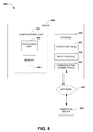
- FIG. 8 presents an illustration of an exemplary computing environment within a computing device 802 wherein the techniques presented herein may be implemented.
- Example computing devices include, but are not limited to, personal computers, server computers, hand-held or laptop devices, mobile devices (such as mobile phones, Personal Digital Assistants (PDAs), media players, and the like), multiprocessor systems, consumer electronics, mini computers, mainframe computers, and distributed computing environments that include any of the above systems or devices.
- mobile devices such as mobile phones, Personal Digital Assistants (PDAs), media players, and the like
- PDAs Personal Digital Assistants
- multiprocessor systems consumer electronics, mini computers, mainframe computers, and distributed computing environments that include any of the above systems or devices.
- FIG. 8 illustrates an example of a system 800 comprising a computing device 802 configured to implement one or more embodiments provided herein.
- the computing device 802 includes at least one processor 806 and at least one memory component 808 .
- the memory component 808 may be volatile (such as RAM, for example), non-volatile (such as ROM, flash memory, etc., for example) or an intermediate or hybrid type of memory component. This configuration is illustrated in FIG. 8 by dashed line 804 .
- device 802 may include additional features and/or functionality.
- device 802 may include one or more additional storage components 810 , including, but not limited to, a hard disk drive, a solid-state storage device, and/or other removable or non-removable magnetic or optical media.
- additional storage components 810 including, but not limited to, a hard disk drive, a solid-state storage device, and/or other removable or non-removable magnetic or optical media.
- computer-readable and processor-executable instructions implementing one or more embodiments provided herein are stored in the storage component 810 .
- the storage component 810 may also store other data objects, such as components of an operating system, executable binaries comprising one or more applications, programming libraries (e.g., application programming interfaces (APIs), media objects, and documentation.
- the computer-readable instructions may be loaded in the memory component 808 for execution by the processor 806 .
- the computing device 802 may also include one or more communication components 816 that allows the computing device 802 to communicate with other devices.
- the one or more communication components 816 may comprise (e.g.) a modem, a Network Interface Card (NIC), a radiofrequency transmitter/receiver, an infrared port, and a universal serial bus (USB) USB connection.
- NIC Network Interface Card
- USB universal serial bus
- Such communication components 816 may comprise a wired connection (connecting to a network through a physical cord, cable, or wire) or a wireless connection (communicating wirelessly with a networking device, such as through visible light, infrared, or one or more radiofrequencies.
- the computing device 802 may include one or more input components 814 , such as keyboard, mouse, pen, voice input device, touch input device, infrared cameras, or video input devices, and/or one or more output components 812 , such as one or more displays, speakers, and printers.
- the input components 814 and/or output components 812 may be connected to the computing device 802 via a wired connection, a wireless connection, or any combination thereof.
- an input component 814 or an output component 812 from another computing device may be used as input components 814 and/or output components 812 for the computing device 802 .
- the components of the computing device 802 may be connected by various interconnects, such as a bus.
- interconnects may include a Peripheral Component Interconnect (PCI), such as PCI Express, a Universal Serial Bus (USB), firewire (IEEE 794), an optical bus structure, and the like.
- PCI Peripheral Component Interconnect
- USB Universal Serial Bus
- IEEE 794 Firewire
- optical bus structure and the like.
- components of the computing device 802 may be interconnected by a network.
- the memory component 808 may be comprised of multiple physical memory units located in different physical locations interconnected by a network.
- a computing device 820 accessible via a network 818 may store computer readable instructions to implement one or more embodiments provided herein.
- the computing device 802 may access the computing device 820 and download a part or all of the computer readable instructions for execution.
- the computing device 802 may download pieces of the computer readable instructions, as needed, or some instructions may be executed at the computing device 802 and some at computing device 820 .
- a component may be, but is not limited to being, a process running on a processor, a processor, an object, an executable, a thread of execution, a program, and/or a computer.
- an application running on a controller and the controller can be a component.
- One or more components may reside within a process and/or thread of execution and a component may be localized on one computer and/or distributed between two or more computers.
- the claimed subject matter may be implemented as a method, apparatus, or article of manufacture using standard programming and/or engineering techniques to produce software, firmware, hardware, or any combination thereof to control a computer to implement the disclosed subject matter.
- article of manufacture as used herein is intended to encompass a computer program accessible from any computer-readable device, carrier, or media.
- one or more of the operations described may constitute computer readable instructions stored on one or more computer readable media, which if executed by a computing device, will cause the computing device to perform the operations described.
- the order in which some or all of the operations are described should not be construed as to imply that these operations are necessarily order dependent. Alternative ordering will be appreciated by one skilled in the art having the benefit of this description. Further, it will be understood that not all operations are necessarily present in each embodiment provided herein.
- the word “exemplary” is used herein to mean serving as an example, instance, or illustration. Any aspect or design described herein as “exemplary” is not necessarily to be construed as advantageous over other aspects or designs. Rather, use of the word exemplary is intended to present concepts in a concrete fashion.
- the term “or” is intended to mean an inclusive “or” rather than an exclusive “or”. That is, unless specified otherwise, or clear from context, “X employs A or B” is intended to mean any of the natural inclusive permutations. That is, if X employs A; X employs B; or X employs both A and B, then “X employs A or B” is satisfied under any of the foregoing instances.
- the articles “a” and “an” as used in this application and the appended claims may generally be construed to mean “one or more” unless specified otherwise or clear from context to be directed to a singular form.
Landscapes
- Engineering & Computer Science (AREA)
- Physics & Mathematics (AREA)
- General Engineering & Computer Science (AREA)
- Computer Hardware Design (AREA)
- Thermal Sciences (AREA)
- Microelectronics & Electronic Packaging (AREA)
- Combustion & Propulsion (AREA)
- Chemical & Material Sciences (AREA)
- Fluid Mechanics (AREA)
- Mechanical Engineering (AREA)
- Cooling Or The Like Of Electrical Apparatus (AREA)
- Health & Medical Sciences (AREA)
- Artificial Intelligence (AREA)
- Computer Vision & Pattern Recognition (AREA)
- Evolutionary Computation (AREA)
- Medical Informatics (AREA)
- Software Systems (AREA)
- General Physics & Mathematics (AREA)
- Automation & Control Theory (AREA)
Abstract
Description
Claims (20)
Priority Applications (1)
| Application Number | Priority Date | Filing Date | Title |
|---|---|---|---|
| US13/714,714 US9541299B2 (en) | 2012-12-14 | 2012-12-14 | Setting-independent climate regulator control |
Applications Claiming Priority (1)
| Application Number | Priority Date | Filing Date | Title |
|---|---|---|---|
| US13/714,714 US9541299B2 (en) | 2012-12-14 | 2012-12-14 | Setting-independent climate regulator control |
Publications (2)
| Publication Number | Publication Date |
|---|---|
| US20140172185A1 US20140172185A1 (en) | 2014-06-19 |
| US9541299B2 true US9541299B2 (en) | 2017-01-10 |
Family
ID=50931842
Family Applications (1)
| Application Number | Title | Priority Date | Filing Date |
|---|---|---|---|
| US13/714,714 Active 2034-05-12 US9541299B2 (en) | 2012-12-14 | 2012-12-14 | Setting-independent climate regulator control |
Country Status (1)
| Country | Link |
|---|---|
| US (1) | US9541299B2 (en) |
Cited By (1)
| Publication number | Priority date | Publication date | Assignee | Title |
|---|---|---|---|---|
| US20160044822A1 (en) * | 2013-04-04 | 2016-02-11 | Denso Corporation | Opening and closing control system and opening and closing control apparatus |
Families Citing this family (1)
| Publication number | Priority date | Publication date | Assignee | Title |
|---|---|---|---|---|
| US9829867B2 (en) * | 2014-09-12 | 2017-11-28 | Celestica Technology Consultancy (Shanghai) Co., Ltd. | Fan control system and method thereof |
Citations (40)
| Publication number | Priority date | Publication date | Assignee | Title |
|---|---|---|---|---|
| US4874127A (en) * | 1987-11-12 | 1989-10-17 | Collier William R | Climate control apparatus |
| US5332886A (en) * | 1991-04-11 | 1994-07-26 | E.G.O. Elektro-Gerate Blanc U. Fischer | Sensor correcting temperature regulator for electric heating apparatuses |
| US6023402A (en) | 1998-02-11 | 2000-02-08 | Compact Computer Corporation | Software controlled fan with hardware fail-safe restart |
| US6270319B1 (en) * | 1999-02-04 | 2001-08-07 | Dell Usa, L.P. | Multiple fan having means for reducing beat frequency oscillations |
| US20030011984A1 (en) * | 2001-07-13 | 2003-01-16 | Chu Herman W. | Method and system for controlling a cooling fan within a computer system |
| US20040100765A1 (en) | 2002-11-27 | 2004-05-27 | Internationa Business Machines Corporation | Server blade chassis with airflow bypass damper engaging upon blade removal |
| US20040132398A1 (en) | 2002-10-25 | 2004-07-08 | Sharp Anthony C. | Integrated cabinet for containing electronic equipment |
| US20040218355A1 (en) | 2003-04-30 | 2004-11-04 | Bash Cullen Edwin | Electronics rack having an angled panel |
| US20040217072A1 (en) | 2003-04-30 | 2004-11-04 | Bash Cullen Edwin | Louvered rack |
| US6826456B1 (en) * | 2001-05-04 | 2004-11-30 | Rlx Technologies, Inc. | System and method for controlling server chassis cooling fans |
| US20050030171A1 (en) * | 2003-08-06 | 2005-02-10 | Tse-Hung Liu | Cooling system for computing device |
| US20050182523A1 (en) | 2003-04-07 | 2005-08-18 | Degree C. | Intelligent networked fan assisted tiles for adaptive thermal management of thermally sensitive rooms |
| US6996441B1 (en) | 2002-03-11 | 2006-02-07 | Advanced Micro Devices, Inc. | Forward-looking fan control using system operation information |
| US20080232974A1 (en) * | 2007-03-22 | 2008-09-25 | Nec Corporation | Fan rotation control method, fan rotation control system, and fan rotation control program |
| US20080306635A1 (en) * | 2007-06-11 | 2008-12-11 | Rozzi James A | Method of optimizing air mover performance characteristics to minimize temperature variations in a computing system enclosure |
| US20090205416A1 (en) | 2008-02-15 | 2009-08-20 | International Business Machines Corporation | Monitoring method and system for determining rack airflow rate and rack power consumption |
| US20100110633A1 (en) | 2007-04-05 | 2010-05-06 | Yekutiel Gigushinsky | integrated active cooled cabinet/rack for electronic equipments |
| US20100286843A1 (en) | 2008-02-08 | 2010-11-11 | Coolit Systems Inc. | Air conditioning system control |
| US20110054705A1 (en) | 2009-09-03 | 2011-03-03 | Sun Microsystems, Inc. | System and method for controlling computer system fan speed |
| US20110093856A1 (en) | 2009-10-15 | 2011-04-21 | International Business Machines Corporation | Thermal-Based Job Scheduling Among Server Chassis Of A Data Center |
| US7948196B2 (en) | 2008-04-09 | 2011-05-24 | International Business Machines Corporation | Plurality of configurable independent compute nodes sharing a fan assembly |
| US20110125452A1 (en) | 2006-12-22 | 2011-05-26 | Bash Cullen E | Apparatus state determination method and system |
| US20110128699A1 (en) | 2009-11-30 | 2011-06-02 | Ali Heydari | Cooling servers in a data center using fans external to servers |
| US20110160916A1 (en) | 2009-12-24 | 2011-06-30 | Bahali Sumanta K | Fan speed control of rack devices where sum of device airflows is greater than maximum airflow of rack |
| US20110176275A1 (en) | 2010-01-20 | 2011-07-21 | Fujitsu Limited | Cooling controlling apparatus, electronic apparatus, and cooling controlling method |
| US20110224837A1 (en) * | 2010-03-10 | 2011-09-15 | Dell Products L.P. | System and Method for Controlling Temperature in an Information Handling System |
| US20110228471A1 (en) | 2010-03-16 | 2011-09-22 | Daniel Humphrey | Fan control system and method |
| US20110292601A1 (en) | 2010-05-26 | 2011-12-01 | International Business Machines Corporation | Dehumidifying and re-humidifying apparatus and method for an electronics rack |
| US20110307103A1 (en) * | 2008-07-07 | 2011-12-15 | Ecofactor, Inc. | System and method for using ramped setpoint temperature variation with networked thermostats to improve efficiency |
| US20120010754A1 (en) | 2010-07-09 | 2012-01-12 | International Business Machines Corporation | Adaptive cooling system and method |
| US8165727B2 (en) * | 2005-08-30 | 2012-04-24 | Kabushiki Kaisha Toshiba | Information processing apparatus and cooling control method |
| US20120116590A1 (en) | 2010-11-04 | 2012-05-10 | Dell Products L.P. | Rack-level modular server and storage framework |
| US20120226922A1 (en) | 2011-03-04 | 2012-09-06 | Zhikui Wang | Capping data center power consumption |
| US20130055744A1 (en) | 2011-09-07 | 2013-03-07 | Richard H. Travers | Auxiliary ambient air refrigeration system for cooling and controlling humidity in an enclosure |
| US20130098599A1 (en) * | 2011-10-19 | 2013-04-25 | International Business Machines Corporation | Independent computer system zone cooling responsive to zone power consumption |
| US20130128455A1 (en) * | 2011-11-17 | 2013-05-23 | Cisco Technology, Inc. | Environmental control for module housing electronic equipment racks |
| US20130158713A1 (en) * | 2011-12-14 | 2013-06-20 | International Business Machines Corporation | Integrating a data center thermal control system and individual fan controllers for controlling a thermal environment in a data center room |
| US20140052429A1 (en) * | 2012-08-20 | 2014-02-20 | International Business Machines Corporation | Proactive data center cooling |
| US20140117908A1 (en) * | 2012-10-30 | 2014-05-01 | International Business Machines Corporation | Dynamically modified fan speed table for cooling a computer |
| US8899060B2 (en) | 2011-06-30 | 2014-12-02 | International Business Machines Corporation | Methods and apparatus for cooling electronics |
-
2012
- 2012-12-14 US US13/714,714 patent/US9541299B2/en active Active
Patent Citations (42)
| Publication number | Priority date | Publication date | Assignee | Title |
|---|---|---|---|---|
| US4874127A (en) * | 1987-11-12 | 1989-10-17 | Collier William R | Climate control apparatus |
| US5332886A (en) * | 1991-04-11 | 1994-07-26 | E.G.O. Elektro-Gerate Blanc U. Fischer | Sensor correcting temperature regulator for electric heating apparatuses |
| US6023402A (en) | 1998-02-11 | 2000-02-08 | Compact Computer Corporation | Software controlled fan with hardware fail-safe restart |
| US6270319B1 (en) * | 1999-02-04 | 2001-08-07 | Dell Usa, L.P. | Multiple fan having means for reducing beat frequency oscillations |
| US6826456B1 (en) * | 2001-05-04 | 2004-11-30 | Rlx Technologies, Inc. | System and method for controlling server chassis cooling fans |
| US20030011984A1 (en) * | 2001-07-13 | 2003-01-16 | Chu Herman W. | Method and system for controlling a cooling fan within a computer system |
| US6643128B2 (en) * | 2001-07-13 | 2003-11-04 | Hewlett-Packard Development Company, Lp. | Method and system for controlling a cooling fan within a computer system |
| US6996441B1 (en) | 2002-03-11 | 2006-02-07 | Advanced Micro Devices, Inc. | Forward-looking fan control using system operation information |
| US20040132398A1 (en) | 2002-10-25 | 2004-07-08 | Sharp Anthony C. | Integrated cabinet for containing electronic equipment |
| US20040100765A1 (en) | 2002-11-27 | 2004-05-27 | Internationa Business Machines Corporation | Server blade chassis with airflow bypass damper engaging upon blade removal |
| US20050182523A1 (en) | 2003-04-07 | 2005-08-18 | Degree C. | Intelligent networked fan assisted tiles for adaptive thermal management of thermally sensitive rooms |
| US20040218355A1 (en) | 2003-04-30 | 2004-11-04 | Bash Cullen Edwin | Electronics rack having an angled panel |
| US20040217072A1 (en) | 2003-04-30 | 2004-11-04 | Bash Cullen Edwin | Louvered rack |
| US20050030171A1 (en) * | 2003-08-06 | 2005-02-10 | Tse-Hung Liu | Cooling system for computing device |
| US8165727B2 (en) * | 2005-08-30 | 2012-04-24 | Kabushiki Kaisha Toshiba | Information processing apparatus and cooling control method |
| US8845188B2 (en) | 2006-12-22 | 2014-09-30 | Hewlett-Packard Development Company, L.P. | Apparatus state determination method and system |
| US20110125452A1 (en) | 2006-12-22 | 2011-05-26 | Bash Cullen E | Apparatus state determination method and system |
| US20080232974A1 (en) * | 2007-03-22 | 2008-09-25 | Nec Corporation | Fan rotation control method, fan rotation control system, and fan rotation control program |
| US20100110633A1 (en) | 2007-04-05 | 2010-05-06 | Yekutiel Gigushinsky | integrated active cooled cabinet/rack for electronic equipments |
| US20080306635A1 (en) * | 2007-06-11 | 2008-12-11 | Rozzi James A | Method of optimizing air mover performance characteristics to minimize temperature variations in a computing system enclosure |
| US20100286843A1 (en) | 2008-02-08 | 2010-11-11 | Coolit Systems Inc. | Air conditioning system control |
| US20090205416A1 (en) | 2008-02-15 | 2009-08-20 | International Business Machines Corporation | Monitoring method and system for determining rack airflow rate and rack power consumption |
| US7948196B2 (en) | 2008-04-09 | 2011-05-24 | International Business Machines Corporation | Plurality of configurable independent compute nodes sharing a fan assembly |
| US20110307103A1 (en) * | 2008-07-07 | 2011-12-15 | Ecofactor, Inc. | System and method for using ramped setpoint temperature variation with networked thermostats to improve efficiency |
| US20110054705A1 (en) | 2009-09-03 | 2011-03-03 | Sun Microsystems, Inc. | System and method for controlling computer system fan speed |
| US20110093856A1 (en) | 2009-10-15 | 2011-04-21 | International Business Machines Corporation | Thermal-Based Job Scheduling Among Server Chassis Of A Data Center |
| US20110128699A1 (en) | 2009-11-30 | 2011-06-02 | Ali Heydari | Cooling servers in a data center using fans external to servers |
| US20110160916A1 (en) | 2009-12-24 | 2011-06-30 | Bahali Sumanta K | Fan speed control of rack devices where sum of device airflows is greater than maximum airflow of rack |
| US20110176275A1 (en) | 2010-01-20 | 2011-07-21 | Fujitsu Limited | Cooling controlling apparatus, electronic apparatus, and cooling controlling method |
| US20110224837A1 (en) * | 2010-03-10 | 2011-09-15 | Dell Products L.P. | System and Method for Controlling Temperature in an Information Handling System |
| US20110228471A1 (en) | 2010-03-16 | 2011-09-22 | Daniel Humphrey | Fan control system and method |
| US20110292601A1 (en) | 2010-05-26 | 2011-12-01 | International Business Machines Corporation | Dehumidifying and re-humidifying apparatus and method for an electronics rack |
| US20120010754A1 (en) | 2010-07-09 | 2012-01-12 | International Business Machines Corporation | Adaptive cooling system and method |
| US20120116590A1 (en) | 2010-11-04 | 2012-05-10 | Dell Products L.P. | Rack-level modular server and storage framework |
| US20120226922A1 (en) | 2011-03-04 | 2012-09-06 | Zhikui Wang | Capping data center power consumption |
| US8899060B2 (en) | 2011-06-30 | 2014-12-02 | International Business Machines Corporation | Methods and apparatus for cooling electronics |
| US20130055744A1 (en) | 2011-09-07 | 2013-03-07 | Richard H. Travers | Auxiliary ambient air refrigeration system for cooling and controlling humidity in an enclosure |
| US20130098599A1 (en) * | 2011-10-19 | 2013-04-25 | International Business Machines Corporation | Independent computer system zone cooling responsive to zone power consumption |
| US20130128455A1 (en) * | 2011-11-17 | 2013-05-23 | Cisco Technology, Inc. | Environmental control for module housing electronic equipment racks |
| US20130158713A1 (en) * | 2011-12-14 | 2013-06-20 | International Business Machines Corporation | Integrating a data center thermal control system and individual fan controllers for controlling a thermal environment in a data center room |
| US20140052429A1 (en) * | 2012-08-20 | 2014-02-20 | International Business Machines Corporation | Proactive data center cooling |
| US20140117908A1 (en) * | 2012-10-30 | 2014-05-01 | International Business Machines Corporation | Dynamically modified fan speed table for cooling a computer |
Non-Patent Citations (8)
| Title |
|---|
| Bean, John, "In-Row® RC Cooling of HP C-Ciass Chassis"-Published Date: 2007, pp. 1-5, http://www.apcmedia.com/salestools/KSIH-6Z5SGU-RO-EN.pdf. |
| Kant, Krishna, "Data Center Evolution: A Tutorial on State of the Art, Issues, and Challenges"-Published Date: Dec. 3, 2009, Proceedings: Elsevier Computer Networks Journal, pp. 27 http://www.cse.iitb.ac.in/~puru/courses/spring11/cs620/references/dcevolve.pdf. |
| Kant, Krishna, "Data Center Evolution: A Tutorial on State of the Art, Issues, and Challenges"-Published Date: Dec. 3, 2009, Proceedings: Elsevier Computer Networks Journal, pp. 27 http://www.cse.iitb.ac.in/˜puru/courses/spring11/cs620/references/dcevolve.pdf. |
| Kodama, et al., "Power Reduction Scheme of Fans in a Blade System by Considering the Imbalance of CPU Temperatures"-Published Date: Dec. 18-20, 2010, Proceedings: 2010 IEEE/ACM International Conference on Green computing and Communications, pp. 81-87, http://ieeexplore.ieee.org/stamp/stamp.jsp?tp=&amumber=5724815. |
| Pre-interview First Office Action issued in U.S. Appl. No. 13/530,899 on May 11, 2016, 6 pages. |
| Pre-interview First Office Action issued in U.S. Appl. No. 13/530,899 on Nov. 4, 2016, 4 pages. |
| Pre-interview First Office Action issued in U.S. Appl. No. 13/530,899 on Oct. 23, 2015, 5 pages. |
| Robert C., "Thermal Design Insights into the Dell M91 0 Blade Server"-Published Date: Aug. 11, 2010, pp. 1-2, http://en.community.dell.com/dell-blogs/enterprise/b/inside-enterprise-iUarchive/2010/08/11/thermal-design-insights-into-the-dell-m910-blade-server.aspx. |
Cited By (2)
| Publication number | Priority date | Publication date | Assignee | Title |
|---|---|---|---|---|
| US20160044822A1 (en) * | 2013-04-04 | 2016-02-11 | Denso Corporation | Opening and closing control system and opening and closing control apparatus |
| US10149404B2 (en) * | 2013-04-04 | 2018-12-04 | Denso Corporation | Opening and closing control system and opening and closing control apparatus |
Also Published As
| Publication number | Publication date |
|---|---|
| US20140172185A1 (en) | 2014-06-19 |
Similar Documents
| Publication | Publication Date | Title |
|---|---|---|
| US9658661B2 (en) | Climate regulator control for device enclosures | |
| US10571979B2 (en) | Cooling fan speed control profile | |
| KR102151628B1 (en) | Ssd driven system level thermal management | |
| US9297559B2 (en) | Adaptive thermoelectric cooling in a processor | |
| US8826049B2 (en) | Minimizing airflow using preferential memory allocation by prioritizing memory workload allocation to memory banks according to the locations of memory banks within the enclosure | |
| US9671839B2 (en) | Information handling system dynamic acoustical management | |
| US10390463B2 (en) | Backflow prevention for computing devices | |
| US9116677B2 (en) | System and method for managing a thermal policy of a receiving device that couples to a portable computing device | |
| US9521780B2 (en) | Regulation of airflow and performance in information handling systems after fan failure | |
| US10506743B2 (en) | Systems and methods of automated open-loop thermal control | |
| US11147186B2 (en) | Predictive fan control using workload profiles | |
| US20180267566A1 (en) | Dynamic control of fan floor | |
| US20090187783A1 (en) | Adjusting Cap Settings of Electronic Devices According to Measured Workloads | |
| CN110214298B (en) | System and method for context aware thermal management and workload scheduling in portable computing devices | |
| US20160291656A1 (en) | Method and apparatus for collaborative power and thermal control of fan run time average power limiting | |
| US8103884B2 (en) | Managing power consumption of a computer | |
| US11836028B2 (en) | System and method for closed-loop memory power capping | |
| US20110292802A1 (en) | System and Method for Automatic Throttling of Resources in an Information Handling System Chassis | |
| US9854716B2 (en) | System and method of controlling an air mover | |
| US9541299B2 (en) | Setting-independent climate regulator control | |
| CN110873069A (en) | Method and device for controlling fan parameters | |
| US11500436B2 (en) | System and method for predictive fan speed control and management | |
| US10809778B2 (en) | Systems and methods for information handling system rack and tile airflow coordination | |
| US11755082B2 (en) | Methods and systems for processor-calibrated fan control | |
| CN112470100A (en) | Dynamic thermal control |
Legal Events
| Date | Code | Title | Description |
|---|---|---|---|
| AS | Assignment |
Owner name: MICROSOFT CORPORATION, WASHINGTON Free format text: ASSIGNMENT OF ASSIGNORS INTEREST;ASSIGNORS:SANKAR, SRIRAM;RUBENSTEIN, BRANDON;REEL/FRAME:029476/0393 Effective date: 20121213 |
|
| AS | Assignment |
Owner name: MICROSOFT TECHNOLOGY LICENSING, LLC, WASHINGTON Free format text: ASSIGNMENT OF ASSIGNORS INTEREST;ASSIGNOR:MICROSOFT CORPORATION;REEL/FRAME:034747/0417 Effective date: 20141014 Owner name: MICROSOFT TECHNOLOGY LICENSING, LLC, WASHINGTON Free format text: ASSIGNMENT OF ASSIGNORS INTEREST;ASSIGNOR:MICROSOFT CORPORATION;REEL/FRAME:039025/0454 Effective date: 20141014 |
|
| STCF | Information on status: patent grant |
Free format text: PATENTED CASE |
|
| MAFP | Maintenance fee payment |
Free format text: PAYMENT OF MAINTENANCE FEE, 4TH YEAR, LARGE ENTITY (ORIGINAL EVENT CODE: M1551); ENTITY STATUS OF PATENT OWNER: LARGE ENTITY Year of fee payment: 4 |
|
| MAFP | Maintenance fee payment |
Free format text: PAYMENT OF MAINTENANCE FEE, 8TH YEAR, LARGE ENTITY (ORIGINAL EVENT CODE: M1552); ENTITY STATUS OF PATENT OWNER: LARGE ENTITY Year of fee payment: 8 |