US937385A - Wheel. - Google Patents
Wheel. Download PDFInfo
- Publication number
- US937385A US937385A US43566808A US1908435666A US937385A US 937385 A US937385 A US 937385A US 43566808 A US43566808 A US 43566808A US 1908435666 A US1908435666 A US 1908435666A US 937385 A US937385 A US 937385A
- Authority
- US
- United States
- Prior art keywords
- tire
- wheel
- rim
- tension band
- band
- Prior art date
- Legal status (The legal status is an assumption and is not a legal conclusion. Google has not performed a legal analysis and makes no representation as to the accuracy of the status listed.)
- Expired - Lifetime
Links
Images
Classifications
-
- B—PERFORMING OPERATIONS; TRANSPORTING
- B60—VEHICLES IN GENERAL
- B60C—VEHICLE TYRES; TYRE INFLATION; TYRE CHANGING; CONNECTING VALVES TO INFLATABLE ELASTIC BODIES IN GENERAL; DEVICES OR ARRANGEMENTS RELATED TO TYRES
- B60C7/00—Non-inflatable or solid tyres
- B60C7/10—Non-inflatable or solid tyres characterised by means for increasing resiliency
- B60C7/14—Non-inflatable or solid tyres characterised by means for increasing resiliency using springs
Definitions
- Patented oet. is, isos.
- This invention relates to wheels especially designed for use. on motor-driven vehicles, such as automobiles, the invention relating particularly to the construction of the wheel rim and tire, whereby an ordinary solid rubber tire may be used in connection with the wheel rim, provision being made for imparting the desired elasticity or yielding action to the tire, making the saine practically l
- a further object of 'he invention is to provide means whereby. the tension on the tire may be increased or diminished, according to the exigencies of the case.
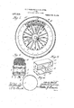
- FIG. 1 is a side elevation, partlyin section, of a wheel embodying the present invention.
- Fig. 2 is a cross section through the rim and tire.
- Fig. 3 is an enlarged detail perspective view of one of the spring members.
- Fig. 4 is'an edge view of the tension band.
- the wheel may embody a hub 1 and spokes 2 of any usual or preferred construction, while the rim 3 may be of metal or wood, according to the desire of the manufacturer.
- the rim 3 is rabbeted along its side edges, as shown at 4, to receive the oppositely arranged annular side plates 5 which are secured to the rim by bolts G or'tlieir equivending.
- a tension band 7 which is made greater than a circle so as to allow the ends thereof to overlap each other. :is-clearly shown in Fig.
- Fig. 9 designates the tread or tire, the inner portion of which is confined between the side plates 5, as best illustrated in Fig. 2.
- Saidi tire or tread may be of rubber or any other suitable material, rubber being preferred.
- the tire is also solid in cross section.
- a circular spring made up of a circular series of spring sections, as shown in Fig. 1, each section being shaped as illustrated in detail in Fig.
- the end portions v11 of the sprin sections maynlso be provided with ho es- 16 to receive coupling pins or connections 17 as shown in' Figs. 1 and but it will, of course, be understood that where the springs are connected by fastenersv 17, such fasteners will be left Sulliciently loose to allow the necessary 'relative play between the spring sections and eccome, inodate the expansion of the tension band 7- 'and the outward movement of the spring sections incident to the expansion of the ten- ⁇ 100 sion band.
Landscapes
- Engineering & Computer Science (AREA)
- Mechanical Engineering (AREA)
- Tires In General (AREA)
Description
o. B.' PARDRIDGE E o; flj. HEMEL.
WHEEL.' v APPLIGAT'ION 11mm Musa, ma.
Eatented o@c.19,19o9.
wit" moes rinrrsii srarnsrnjrnfr orne.
CLINTON E. PARDRIDGE AND OTTO H. HERTEL, F CHICAGO, ILLINOIS, ASSIGNORS 0F ONE-THIRD T0 EDWARD H. LAKEMAN, 0F CHICAGO, ILLINOIS.
WHEEL.
Specification of Letters Patent.
Patented oet. is, isos.
Application filed May 29, 1903. Serial No. 435,666.
Illinois, have invented new and useful Imf provenients lVheels, of which the following is a specification.
This invention relates to wheels especially designed for use. on motor-driven vehicles, such as automobiles, the invention relating particularly to the construction of the wheel rim and tire, whereby an ordinary solid rubber tire may be used in connection with the wheel rim, provision being made for imparting the desired elasticity or yielding action to the tire, making the saine practically l Athe equivalent of the ordinary pneumatic tire now in common use and doing away with the liability of puncturing A further object of 'he invention is to provide means whereby. the tension on the tire may be increased or diminished, according to the exigencies of the case.
With the above 'and other objects in view, the nature of which willmore fully appear as the description roceeds, the invention consists in the noveconstruction, combination and arrangement of4 parts hereinafter fully described, illustrated and claimed.'
In the accompanying drawiiig,-Figure 1 is a side elevation, partlyin section, of a wheel embodying the present invention. Fig. 2 is a cross section through the rim and tire. Fig. 3 is an enlarged detail perspective view of one of the spring members. Fig. 4 is'an edge view of the tension band. i I
The wheel may embody a hub 1 and spokes 2 of any usual or preferred construction, while the rim 3 may be of metal or wood, according to the desire of the manufacturer. In carryin gout the present invention, the rim 3 is rabbeted along its side edges, as shown at 4, to receive the oppositely arranged annular side plates 5 which are secured to the rim by bolts G or'tlieir equivaient. Between the plates and lying closely adjacent to or'in contact with the rim 3 is a tension band 7 which is made greater than a circle so as to allow the ends thereof to overlap each other. :is-clearly shown in Fig.
4, thus providing ior the expansion oi: said band. which is clliectcd by means of a circular series of expanding screws 8 which are inserted through the rim from the inner side, as shown in Figs. 1 and 2,'and bear at their outer ends against the'inner surface of the band. By turning the screws 8 the tension band 7 may be expanded or allowed to contract by its own resiliency.
9 designates the tread or tire, the inner portion of which is confined between the side plates 5, as best illustrated in Fig. 2. Saidi tire or tread may be of rubber or any other suitable material, rubber being preferred. The tire is also solid in cross section. Between the inner fiat surface of the tire 9 and the tension band 7 there is interposed a circular spring made up of a circular series of spring sections, as shown in Fig. 1, each section being shaped as illustrated in detail in Fig. 3, wherein it is seen to comprise an outer fiat portion 10, right-angular or radially disposed end portions 11, inwardly extending return portions 12, radially disposed parallel portions 13, which are arranged close togetherior in 'actual Contact, and outwardly and oppositely extending end portions or terminals 14 which lie Hatwise against the tension band 7 and may be secured thereto by passing bolts, rivets or other fasteners 15 through openings 16 in the end portions 14 and also through corresponding holes in the tension band 7. In this way all of the spring sections are secured to and carried by the tension band and are movable outward and inward therewith when said tension band is expanded by means of the screws 8. The end portions v11 of the sprin sections maynlso be provided with ho es- 16 to receive coupling pins or connections 17 as shown in' Figs. 1 and but it will, of course, be understood that where the springs are connected by fastenersv 17, such fasteners will be left Sulliciently loose to allow the necessary 'relative play between the spring sections and eccome, inodate the expansion of the tension band 7- 'and the outward movement of the spring sections incident to the expansion of the ten-` 100 sion band.
"ly means of the construct-ion above desmibcd. it will be seen that the sprino' sections may be placed under any desired tension by means of the expand in order to accommodate the tire and Wheel ing `screws 8 105 5 is claimed as new, is
The combination with' :i wheel riin, of ennular side plates carried thereby and extending outward beyondthe rim, :i tire heving the inner portion thereof included be- 10 tween said plates, and a circular series of spring sections interposed between the rim and tire, each of, sind sections enibodyinfT curved outerl and inner intermediate concentric portions, and straight radially disposed connecting portions therefor arranged out of radial ulinenient with each other, the
In testimony whereof we aix our signa- 29 tures in presence of two witnesses.
CLINTON E. PARDRIDGE. OTTO H. HERTEL. Titnesses W. BRL-WN, JAMES l. VHALEN.
Priority Applications (1)
| Application Number | Priority Date | Filing Date | Title |
|---|---|---|---|
| US43566808A US937385A (en) | 1908-05-29 | 1908-05-29 | Wheel. |
Applications Claiming Priority (1)
| Application Number | Priority Date | Filing Date | Title |
|---|---|---|---|
| US43566808A US937385A (en) | 1908-05-29 | 1908-05-29 | Wheel. |
Publications (1)
| Publication Number | Publication Date |
|---|---|
| US937385A true US937385A (en) | 1909-10-19 |
Family
ID=3005806
Family Applications (1)
| Application Number | Title | Priority Date | Filing Date |
|---|---|---|---|
| US43566808A Expired - Lifetime US937385A (en) | 1908-05-29 | 1908-05-29 | Wheel. |
Country Status (1)
| Country | Link |
|---|---|
| US (1) | US937385A (en) |
Cited By (1)
| Publication number | Priority date | Publication date | Assignee | Title |
|---|---|---|---|---|
| US4087879A (en) * | 1975-01-10 | 1978-05-09 | Forrest Spence | Shag rug brushing and object retrieving device |
-
1908
- 1908-05-29 US US43566808A patent/US937385A/en not_active Expired - Lifetime
Cited By (1)
| Publication number | Priority date | Publication date | Assignee | Title |
|---|---|---|---|---|
| US4087879A (en) * | 1975-01-10 | 1978-05-09 | Forrest Spence | Shag rug brushing and object retrieving device |
Similar Documents
| Publication | Publication Date | Title |
|---|---|---|
| US1060480A (en) | Resilient wheel. | |
| US937385A (en) | Wheel. | |
| US1300933A (en) | Resilient tire. | |
| US1217724A (en) | Vehicle-wheel. | |
| US989701A (en) | Resilient wheel. | |
| US1035410A (en) | Spring-wheel. | |
| US1069452A (en) | Punctureless spring-tire. | |
| GB191022452A (en) | Improvements in Spring Wheels for Motor and other Vehicles, Cycles and other purposes. | |
| US1078876A (en) | Metallic wheel-tire. | |
| US865411A (en) | Cushion-tire wheel. | |
| US1007088A (en) | Vehicle-wheel. | |
| US1020901A (en) | Wheel. | |
| US987891A (en) | Wheel. | |
| US1237065A (en) | Automobile-wheel. | |
| US1107093A (en) | Vehicle-wheel. | |
| US968643A (en) | Spring-wheel. | |
| US1197254A (en) | Spring-wheel. | |
| US1137509A (en) | Resilient wheel. | |
| US1061799A (en) | Spring-wheel. | |
| US805673A (en) | Vehicle-wheel. | |
| US974765A (en) | Spring-wheel. | |
| US1285419A (en) | Vehicle-tire. | |
| US1400807A (en) | Vehicle-wheel | |
| US989190A (en) | Wheel. | |
| US1039857A (en) | Spring-wheel. |