US934616A - Oil-burner. - Google Patents
Oil-burner. Download PDFInfo
- Publication number
- US934616A US934616A US45870608A US1908458706A US934616A US 934616 A US934616 A US 934616A US 45870608 A US45870608 A US 45870608A US 1908458706 A US1908458706 A US 1908458706A US 934616 A US934616 A US 934616A
- Authority
- US
- United States
- Prior art keywords
- air
- spreader
- vapor
- pipe
- cup
- Prior art date
- Legal status (The legal status is an assumption and is not a legal conclusion. Google has not performed a legal analysis and makes no representation as to the accuracy of the status listed.)
- Expired - Lifetime
Links
Images
Classifications
-
- F—MECHANICAL ENGINEERING; LIGHTING; HEATING; WEAPONS; BLASTING
- F23—COMBUSTION APPARATUS; COMBUSTION PROCESSES
- F23D—BURNERS
- F23D5/00—Burners in which liquid fuel evaporates in the combustion space, with or without chemical conversion of evaporated fuel
Definitions
- the supthe following is a specitication -duce a/hur-ner in which the tlow of vapor t structed, and the invention consists of the p novel features ⁇ hereinv shown, described ⁇ and 'bracket- 9 is attached at its ends to the sup;
- An object of this invention is to produce an oil-burner for use of di'stillates which will not overheat the oil inthe supply-pipe, and in which the vaporizing-cup is readily accessible @for cleaning.
- a further object ofthe invention is to pro# and the tlw ofl air at ⁇ the point wherethe vapor and air mix is absolutely unob-Y clailned.
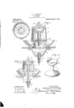
- Figure 1 is a vertical central section on line m1
- Fig. 2 is a vertical central section on a reduced scale on line mi.
- Fig. 3 is avplan of the'combastion-pan with the vapor-spreader reinoved.
- Fig. l is a perspective of the vapo ⁇ rizing-cup,l stand-pipe, and air-spreader renioved from the burner.
- the support 1 may be the bottom of the.t stove, and a ⁇ central vertical air-passage 2 of considerable size is formed through the support.
- bracket being a considerable distance below the level of the support 1, and said bracket ply-pipe 11 is connected to a couplingj12, and the supply-pipe extension 13 is inserted downwardly through a jam.nut 14, then through the center of the bracket 9 into the coupling 12; said extension extending upwardly to a position above the raised center 4 and at the center of the air-opening 6.
- the air-spreader 15, stand-pipe 16, and vaporizing-cup 17 are formed integral and screwed upon the upper end of the extension supply-pipe 13 so that the air-spreader -covers the opening 6 through the combusextension of the supply-pipe, thereby leading" the oil to the center of the vaporizingcup 17.
- the vaporizing-cup 17 is of less diameter than the air-spreader 15 and isheniispherical in form. Lugs 19 project upwardly from the edge of the-.cup to support the vapor-spreader.
- The-vapor-spreader is in the forin of an inverted cup and?y coniprises a flat top 2O resting upon the lugs 19 aud a downwaidly-extending ri'm 2l, said rim ismer nearly the saine diameter as the air-spreader 15,...and the ⁇ lower edge of the rim being near to the upper face of the airspreader so as toform within the vaporspreader, between the vapo'rizing-cup and the air-spreader, a heating chamber opening through the continuous thin yvapor-passage 22 so that as the vapor passes outwardly through the passage 22 it. will meet the air passing outwardly through the passagelS at.
- a perforatedvear 23 extends upwardly from the top 20 for manipulating the vaporspreader
- the oih is admitted through the supply-pipe to the' vaporizingcup, and overflows the upper edge of the vaporizing-cup and runs down the outer 'surface of the vaporizing-cup, stand-pipe 16, and the air-spreader 15, into thetrough 5, and then the oil is lighted and burns up around l.the vapor-spreader l21 until sutiicient heat is generated to vaporize the oil ⁇ in the cup 17. Then the vapor will pass over the edge of the cup 17 between the lugs "19 and downwardly through the vapor heat.-
- a combustion-pan having a raised ceni ter anda central opening through-the raised center ⁇ a supply-pipe mounted "ertically in said opening, an air-spreader mounted upon I .the pipe, astand-pipe forming an extensionoithe' supply-pipeabove the air-spreader, a 1 vapori'zing-cup upon the vupper end of the stand-pipe, and a vapor-spreader in the form of an inverted cupeoxf'ering the v'aporizingcup and-,extending .downwardly near to the air-spreader.
- a vapor-spreader mounted ⁇ upon the'vap'orizing-cup and terminating 4nearthetop otl'thev air spreader, so'as to fbring the vapor andairtogethe'r near the perphery of the air-spreader; a chamber being formed within ⁇ tli'e vapor-spreader be ⁇ tweenl lthe cup and theainspreader.
- a combustionpan I having a 'raised cen- A Ater and an air-passage verticallythrough the raised center, aysupply-pipe at the center y'of the air-passage, and an airfspreader upon spreader the supply-pipe immediately above the raised center, said air-spreade being larger than the opening through the raised center; a vaporizlng cup above the 4ani-spreaderr ⁇ and a ⁇ vapor-'spreader upon the vapo'rizing-cup spaced apart from and discharging vapor ai. the periphery'of the air-spreader; a chamber being formed within the. vapor-spreader between thecup and the air-spreader.
Landscapes
- Engineering & Computer Science (AREA)
- Chemical & Material Sciences (AREA)
- Combustion & Propulsion (AREA)
- Mechanical Engineering (AREA)
- General Engineering & Computer Science (AREA)
- Spray-Type Burners (AREA)
Description
A. K. LNnLBY.
OIL BURNER.
QPPLIUATION FILED 00,120, 1908.
934,6 1 6, Patented; Sept. 2L iQQ. im?. x
being crosswise of theopening 2. The supthe following is a specitication -duce a/hur-ner in which the tlow of vapor t structed, and the invention consists of the p novel features `hereinv shown, described `and 'bracket- 9 is attached at its ends to the sup;
port 1 by tap-screws 10, the center of the?" ANDREW K. LINDLEY, 0F LOSANGELES., CALIFORNIA.
0in-nuance.
Application filed October 20,
' Specification 0f LettcrSPatent Patentedsept. 21, 1min.
190s. serialv up. 458,7oef
To Aall whom it may concern:
Be it known that LfANonEw K. LINDLEY, a citizen of the United States, residing at Los Angeles, in the Acounty of Los Angeles and State of Californiaghave invented anew' and useful Improved Oil-Burner, of which An object of this invention is to produce an oil-burner for use of di'stillates which will not overheat the oil inthe supply-pipe, and in which the vaporizing-cup is readily accessible @for cleaning..
A further object ofthe invention is to pro# and the tlw ofl air at` the point wherethe vapor and air mix is absolutely unob-Y clailned.
Th'accompanying drawing illustrates the invention.y
Figure 1 is a vertical central section on line m1, Figs. 2 and 3.- Fig. 2 is a vertical central section on a reduced scale on line mi., Figs. 1 and 3. Fig. 3 is avplan of the'combastion-pan with the vapor-spreader reinoved.- Fig. l is a perspective of the vapo` rizing-cup,l stand-pipe, and air-spreader renioved from the burner. u
The support 1 may be the bottom of the.t stove, and a` central vertical air-passage 2 of considerable size is formed through the support. The coinluistion-pauYcomprises the rim 3, the raised center 4 forming th'e annular glitter 5 and the central air-passage 6, there being lugs 7 extendingr downwardly from the metal of the raised center 4 into notches 8 extending from the air-opening 2 into the support 1 to hold the vaporiziugpan ina central position with the air-openmg 6in registration with the openin'g 2. A
bracket being a considerable distance below the level of the support 1, and said bracket ply-pipe 11 is connected to a couplingj12, and the supply-pipe extension 13 is inserted downwardly through a jam.nut 14, then through the center of the bracket 9 into the coupling 12; said extension extending upwardly to a position above the raised center 4 and at the center of the air-opening 6.
The air-spreader 15, stand-pipe 16, and vaporizing-cup 17 are formed integral and screwed upon the upper end of the extension supply-pipe 13 so that the air-spreader -covers the opening 6 through the combusextension of the supply-pipe, thereby leading" the oil to the center of the vaporizingcup 17. The vaporizing-cup 17 is of less diameter than the air-spreader 15 and isheniispherical in form. Lugs 19 project upwardly from the edge of the-.cup to support the vapor-spreader. The-vapor-spreader is in the forin of an inverted cup and?y coniprises a flat top 2O resting upon the lugs 19 aud a downwaidly-extending ri'm 2l, said rim beimr nearly the saine diameter as the air-spreader 15,...and the `lower edge of the rim being near to the upper face of the airspreader so as toform within the vaporspreader, between the vapo'rizing-cup and the air-spreader, a heating chamber opening through the continuous thin yvapor-passage 22 so that as the vapor passes outwardly through the passage 22 it. will meet the air passing outwardly through the passagelS at. the peripheral edge of the air-spreader 15. A perforatedvear 23 extends upwardly from the top 20 for manipulating the vaporspreader When it is "desired to clean the T11 practical operation the oih is admitted through the supply-pipe to the' vaporizingcup, and overflows the upper edge of the vaporizing-cup and runs down the outer 'surface of the vaporizing-cup, stand-pipe 16, and the air-spreader 15, into thetrough 5, and then the oil is lighted and burns up around l.the vapor-spreader l21 until sutiicient heat is generated to vaporize the oil `in the cup 17. Then the vapor will pass over the edge of the cup 17 between the lugs "19 and downwardly through the vapor heat.-
ing chamber' inside of the vapor-spreader 21,l and through the vapor-passage 22, and
`fresh air will pass upwardly around the bracket 9, through the opening 2, through the opening 6, and through the opening 18; the air and vapor meeting at the edge of the air-s reader 15, thereby causing a continuous t in flame to encircle the vapor-spreader 21, and furnishing suiicient 'heat to continue the process of vaporizing the oil in the cup 17 l By experimentation and calculation the p parts are so proportioned that the flame thus y Y in producing 10y produced will not overheat the standpipe 16 so as'to clog the stand-pipe. By mounting" theparts as shown and described I-produce a continuous flame of'practically equal inf tensity all the way around by passing the vapor through the narrowcontinuous slit 22, and the air through the narrow continu! ous slitrlS, and this is of great importance asmokeless Hamein an airdraft burner.- y i I claim A l f 1. A combustion-pan having a raised ceni ter anda central opening through-the raised center` a supply-pipe mounted "ertically in said opening, an air-spreader mounted upon I .the pipe, astand-pipe forming an extensionoithe' supply-pipeabove the air-spreader, a 1 vapori'zing-cup upon the vupper end of the stand-pipe, and a vapor-spreader in the form of an inverted cupeoxf'ering the v'aporizingcup and-,extending .downwardly near to the air-spreader. u f
2. A combustion-pan `having a raised cen' tverandv an air-passage 'through "the raised center, a supply-pipe extending upwardly through the uiiepassage, an "air-spreader' upon the vsupply-pipe,l a vaporizing-cup above. and spaced vapart from 'the airspreademv and a vapor-spreader mounted `upon the'vap'orizing-cup and terminating 4nearthetop otl'thev air spreader, so'as to fbring the vapor andairtogethe'r near the perphery of the air-spreader; a chamber being formed within `tli'e vapor-spreader be` tweenl lthe cup and theainspreader.
3. A combustionpan Ihaving a 'raised cen- A Ater and an air-passage verticallythrough the raised center, aysupply-pipe at the center y'of the air-passage, and an airfspreader upon spreader the supply-pipe immediately above the raised center, said air-spreade being larger than the opening through the raised center; a vaporizlng cup above the 4ani-spreaderr `and a `vapor-'spreader upon the vapo'rizing-cup spaced apart from and discharging vapor ai. the periphery'of the air-spreader; a chamber being formed within the. vapor-spreader between thecup and the air-spreader. i
4. A supportA having!I a 'vertical air-passage,' a bracket secured tothe bottom of the support, a combuston.pan upon the support and having a vertical air-passage registering withthe air-passage througlr the support, a supply-'pipe' secured. to .and extending tlhrougflithe bracketand through f the' air-passages of the support land vthe .coni'bustion-pan, an air-spreader. upony :the
supply pipe 'largen tlianf the air passage through the combustlon-pan, thus forming a, thin continuous slitv for thepassage of an-,V
a stand-pipe .extendingnpwardly frointhe air-spreadenand forming an extension -oi the supplypipe,la ,vaporizi'ng-cup upon the upper end of the stand-pipe, lugs extending upwardly fromfthe edge of the vaporizigcup, and a .Yapoiyspreader covering the -vap-A orizing-cup and extending downwardly and formingv a thin slit vfor the discharge ot' vapor between the lower edge of the vaporandl' vthe periphery 'of thegair`
Priority Applications (1)
| Application Number | Priority Date | Filing Date | Title |
|---|---|---|---|
| US45870608A US934616A (en) | 1908-10-20 | 1908-10-20 | Oil-burner. |
Applications Claiming Priority (1)
| Application Number | Priority Date | Filing Date | Title |
|---|---|---|---|
| US45870608A US934616A (en) | 1908-10-20 | 1908-10-20 | Oil-burner. |
Publications (1)
| Publication Number | Publication Date |
|---|---|
| US934616A true US934616A (en) | 1909-09-21 |
Family
ID=3003039
Family Applications (1)
| Application Number | Title | Priority Date | Filing Date |
|---|---|---|---|
| US45870608A Expired - Lifetime US934616A (en) | 1908-10-20 | 1908-10-20 | Oil-burner. |
Country Status (1)
| Country | Link |
|---|---|
| US (1) | US934616A (en) |
Cited By (1)
| Publication number | Priority date | Publication date | Assignee | Title |
|---|---|---|---|---|
| US2443707A (en) * | 1943-03-19 | 1948-06-22 | Stewart Warner Corp | Hot-air heater with fuel vaporizer and air mixer |
-
1908
- 1908-10-20 US US45870608A patent/US934616A/en not_active Expired - Lifetime
Cited By (1)
| Publication number | Priority date | Publication date | Assignee | Title |
|---|---|---|---|---|
| US2443707A (en) * | 1943-03-19 | 1948-06-22 | Stewart Warner Corp | Hot-air heater with fuel vaporizer and air mixer |
Similar Documents
| Publication | Publication Date | Title |
|---|---|---|
| US934616A (en) | Oil-burner. | |
| US956695A (en) | Crude-oil burner. | |
| US1240804A (en) | Steam-boiler. | |
| US1090402A (en) | Burner. | |
| US928620A (en) | Oil-burner. | |
| US939415A (en) | Gas or oil burner. | |
| US1223141A (en) | Oil-burner. | |
| US1438684A (en) | belair | |
| US2373310A (en) | Tubular pilot | |
| US2671505A (en) | Crude oil burner | |
| US690071A (en) | Liquid-fuel-heater burner. | |
| US1621447A (en) | Automatic mechanically-operated oil burner | |
| US396525A (en) | Oil-burner | |
| US1002300A (en) | Coal-oil burner. | |
| US649881A (en) | Hydrocarbon-burner. | |
| US559670A (en) | Hydrocarbon-burner | |
| US689785A (en) | Hydrocarbon-burner. | |
| US760703A (en) | Hydrocarbon-burner. | |
| US1167605A (en) | Oil-burner. | |
| US973804A (en) | Gas-generating oil-burner. | |
| US769112A (en) | Hydrocarbon-burner. | |
| US612118A (en) | Charles henry myers | |
| US998835A (en) | Hydrocarbon-burner. | |
| US709370A (en) | Oil-burner. | |
| US243495A (en) | Hydrocarbon-gas stove |