US9108735B2 - Electro-expulsive de-icing system for aircraft and other applications - Google Patents
Electro-expulsive de-icing system for aircraft and other applications Download PDFInfo
- Publication number
- US9108735B2 US9108735B2 US12/658,304 US65830410A US9108735B2 US 9108735 B2 US9108735 B2 US 9108735B2 US 65830410 A US65830410 A US 65830410A US 9108735 B2 US9108735 B2 US 9108735B2
- Authority
- US
- United States
- Prior art keywords
- electrically conductive
- subassembly
- actuator
- electro
- icing
- Prior art date
- Legal status (The legal status is an assumption and is not a legal conclusion. Google has not performed a legal analysis and makes no representation as to the accuracy of the status listed.)
- Active, expires
Links
Images


Classifications
-
- B—PERFORMING OPERATIONS; TRANSPORTING
- B64—AIRCRAFT; AVIATION; COSMONAUTICS
- B64D—EQUIPMENT FOR FITTING IN OR TO AIRCRAFT; FLIGHT SUITS; PARACHUTES; ARRANGEMENT OR MOUNTING OF POWER PLANTS OR PROPULSION TRANSMISSIONS IN AIRCRAFT
- B64D15/00—De-icing or preventing icing on exterior surfaces of aircraft
- B64D15/16—De-icing or preventing icing on exterior surfaces of aircraft by mechanical means, e.g. pulsating mats or shoes attached to, or built into, surface
- B64D15/163—De-icing or preventing icing on exterior surfaces of aircraft by mechanical means, e.g. pulsating mats or shoes attached to, or built into, surface using electro-impulsive devices
Definitions
- This invention relates generally to the field of in-flight aircraft de-icing and the like, and more particularly to an electro-expulsive de-icing system and its component parts for aircraft and other applications.
- An “electro-expulsive de-icing system” is also sometimes referred to as an “electro-mechanical expulsive de-icing system.” It uses electrically produced mechanical motion to knock accumulated ice off a flight surface or other object being de-iced. Recall in that regard that ice removal is an important undertaking because, in the case of aircraft, ice can alter aerodynamic characteristics significantly with catastrophic results. A de-icing system alleviates those concerns.
- a typical electro-expulsive de-icing system includes electro-mechanical transducers called “actuators” that are installed beneath the skin of various aircraft structures (e.g., the leading edges of wings, horizontal and vertical stabilizers, and engine inlets).
- actuators electro-mechanical transducers
- an onboard electronic control system passes large current pulses through such actuators (e.g., 8,000-ampere, millisecond duration pulses at 30 to 90-second intervals) in order to thereby produce mechanical motion that produces shock waves in the skin of the aircraft structure.
- the shock waves result in dislodgement of ice that has accumulated on the skin.
- the actuator impacts the inner surface of the skin, that action produces the shock waves in the skin, and the shock waves knock the accumulated ice off the outer surface of the skin.
- Some such existing electro-expulsive de-icing actuators include strips or ribbons of copper or other electrically conductive material that are mounted beneath the aircraft skin in closely-spaced-apart parallel orientation. Electric current flowing as mentioned above causes the strips to accelerate apart from each other in a manner creating ice-removing shock waves.
- the electrically conductive strips for some actuators take the form of a copper ribbon wrapped in an elongated multi-turn loop (i.e., a multi-turn coil).
- a copper ribbon measuring, for example, 0.25 inches to 1.50 inches wide and 0.020 inches to 0.040 inches thick, is wrapped in a multilayer, elongated, loop measuring about one to eight feet in length, with the copper ribbon being wound back on itself at the ends of the loop. Molded blocks of polyurethane encapsulate the two opposite folded ends of the loop while a dielectric coating on the copper ribbon prevents shorting between adjacent turns.
- Interconnection of the copper ribbon loop to the onboard electronic control system results in electric current pulses flowing in a first direction in a first half of the loop (from a first folded end of the loop to an opposite second folded end), and in an opposite second direction in a second half of the loop (from the second folded end of the loop to the first folded end).
- an electric current pulse flows that way, it results in a large force that tends to mutually repel the first and second halves of the loop. That repulsion results in relative movement of the first and second halves away from each other (e.g., by about 0.08′′ to 0.50′′) in a pulse of mechanical motion that is coupled to the aircraft skin. That mechanical pulse results in the de-icing shock waves.
- the present invention achieves the above-stated objective by providing an actuator assembly that includes an electrically conductive loop formed by two mechanically independent loop subassemblies.
- a first loop subassembly of the two forms a first portion of the electrically conductive loop; current flows in it in a first direction.
- a second loop subassembly of the two forms a second portion of the electrically conductive loop; current flows in it in an opposite second direction.
- the ends of the first and second subassemblies are electrically interconnected by flexible connectors.
- the first and second subassemblies i.e., the first and second portions of the electrically conductive loop
- the first and second subassemblies can move apart without the restrictiveness of encapsulated ends. Displacement is less restricted.
- the fatigue failure previously experienced at encapsulated ends is avoided.
- the inventors of the present invention discovered that mechanical output energy of prior art actuators was being diverted to unproductive deformation and stress in the folded actuator ends and that as a consequence actuator operation was sometimes less robust than desired and the ends of the loop tended to experience the fatigue failure mention previously.
- an apparatus constructed according to the invention for impacting an object as part of an electro-expulsive de-icing system includes an assembly referred to as the actuator.
- the actuator includes multiple electrically conductive elements connected in an electrically conductive loop, and the actuator is mounted on a support structure in a position enabling the loop to impact the object in response to movement of the loop produced by electric current pulses flowing in the loop.
- a first subassembly portion of the actuator includes an electrically conductive first element of the loop having two opposite terminal ends referred to as the “first end” and the “second end.” The first element extends between the first end and the second end along a first path, with the first element functioning as means for conducting the electric current pulses in a first direction.
- a second subassembly portion of the actuator includes an electrically conductive second element of the loop having two opposite terminal ends that are referred to as the “third end” and the “fourth end.” The second element extends between the third end and the fourth end along a second path that is spaced apart from and generally parallel to the first path, with the second element functioning as means for conducting the electric current pulses in a second direction that is generally opposite the first direction.
- means are provided for electrically interconnecting the various terminal ends of the first and second elements in order to thereby form the electrically conductive loop.
- the means for doing so includes at least a first connector that electrically interconnects the second end and the fourth end without preventing movement of the second end relative to the fourth end.
- the first connector includes an electrically conductive first conductor attached to the second end and the fourth end that is flexible (e.g., a jumper formed from a length of stranded aircraft wire).
- an actuator constructed according to the invention preferably includes multiple element pairs and connectors for a multi-turn loop.
- the first subassembly preferably includes a first plurality of electrically conductive elements (e.g., three or four) extending in generally parallel relationship to each other.
- the second subassembly includes a second plurality of electrically conductive elements extending in generally parallel relationship to each other. The ends of those elements are interconnected to form the elongated loop using the elongated flexible connectors mentioned above.
- the invention provides an electro-expulsive de-icing actuator that alleviates performance and fatigue failure concerns of the prior art.
- the enhanced performance offers greater weight savings and design flexibility.
- FIG. 1 of the drawings is a diagrammatic view of the leading-edge structure of an aircraft that shows typical actuator placement, with the leading edge structure and the actuator shown foreshortened for illustrative purposes and with an X-Y-Z Cartesian coordinate system included for use in describing various spatial relationships;
- FIG. 2 a of the drawings is an enlarged cross section of the leading-edge portion that shows some details of actuator mounting
- FIG. 2 b of the drawings is a cross sectional view of the leading-edge portion that is similar to FIG. 2 a , but shows a different actuator placement;
- FIG. 2 c is a cross sectional view of the leading-edge portion that is similar to FIG. 2 a , but shows multiple actuators;
- FIG. 3 is a perspective view of an actuator having encapsulated ends that restrict relative movement of the first and second halves of the electrically conductive loop;
- FIG. 4 is a perspective view of a first embodiment of an actuator constructed according to the present invention that includes an electrically conductive loop formed by two separate subassemblies interconnected by flexible connectors (i.e., jumper wires);
- FIG. 5 is a perspective view of a second embodiment of an actuator constructed according to the present invention that includes a second type of flexible connector;
- FIG. 6 is a perspective view of a third embodiment of an actuator constructed according to the present invention that includes a third type of flexible connector
- FIG. 7 a is an enlarged cross section view of an actuator mounting arrangement
- FIG. 7 b is an enlarged cross section similar to FIG. 7 a , showing the first and second actuator halves (i.e., the first and second subassemblies) separated during a current pulse;
- FIG. 8 is a perspective view of a fourth embodiment of an actuator constructed according to the present invention that includes an electrically conductive loop with four turns;
- FIG. 9 is a radial cross section view of a portion of an aircraft jet engine intake showing one set of multiple actuator pairs arranged in an axially extending placement of multiple actuators;
- FIG. 10 is a diagrammatic view of an aircraft jet engine intake showing axially extending placement of multiple actuators
- FIG. 11 is a diagrammatic view of an aircraft jet engine intake showing circumferentially extending placement of multiple actuators
- FIG. 12 is a diagrammatic representation of the first actuator embodiment that shows various aspects in further detail
- FIG. 13 a is a diagrammatic representation of a flexible connector used to electrically interconnect terminal ends of the various elements forming the electrically conductive loop;
- FIG. 13 b is a diagrammatic representation similar to FIG. 13 a , except that the connector is shown resiliently deformed as it would be in response to relative movement of the two subassemblies that form the electrically conductive loop;
- FIG. 14 shows greater actuation force per unit length within a connector of prior art
- FIG. 15 shows a simple Actuator section magnetic force per unit length
- FIG. 16 a shows lower actuation force per unit length within the invented connector dispersal of actuator current into wide strips
- FIG. 16 b shows lower actuation force per unit length within the invented connector dispersal of actuator current into multiple separated conductors.
- FIG. 1 of the drawings is a diagrammatic representation of an electro-expulsive de-icing system 10 .
- the system 10 includes an electronic control system 11 (i.e., an onboard electro-expulsive de-icing control system) and an actuator 12 that is mounted in a position to impact the skin 13 of an aircraft leading edge structure 14 (i.e., the leading edge portion of a wing, stabilizer, or other aircraft structure).
- an aircraft leading edge structure 14 i.e., the leading edge portion of a wing, stabilizer, or other aircraft structure.
- Various surfaces of an aircraft are formed by a “skin” (e.g., sheets of aluminum or composite material) mounted over a “support structure” (e.g., an aluminum or composite framework), and the system 10 operates to dislodge ice (not shown) that has formed on the skin.
- a “skin” e.g., sheets of aluminum or composite material
- support structure e.g., an aluminum or composite framework
- the actuator 12 responds to electronic pulses from the control system 11 by impacting the skin 13 of the leading edge structure 14 (i.e., an inwardly facing surface 13 A of the skin 13 ), thereby producing shock waves in the skin 13 that dislodge ice that has formed on an outwardly facing surface 13 B of the skin 13 .
- FIGS. 2 a , 2 b , and 2 c illustrate examples of actuator mounting.
- an actuator 12 is shown attached by bonding or other suitable means to the inwardly facing surface 13 A of the skin 13 and to a semi-rigid inner shell 15 A.
- the inner shell 15 A is attached by bonding or other suitable means to the leading edge structure 14 .
- It includes a web structure 16 A referred to as a “shear web” that adds rigidity (e.g., a lightweight, rigid, composite material) and it transfers force between the actuator 12 and another region of the inwardly facing surface 13 A that is identified by a reference numeral 17 A.
- FIG. 1 an actuator 12 is shown attached by bonding or other suitable means to the inwardly facing surface 13 A of the skin 13 and to a semi-rigid inner shell 15 A.
- the inner shell 15 A is attached by bonding or other suitable means to the leading edge structure 14 .
- It includes a web structure 16 A referred to as a “shear web”
- FIG. 2 b shows an actuator 12 A bonded to an inner shell 15 B between first and second web structures 16 B and 16 C.
- the first and second web structures 16 B and 16 C transfer force between the actuator 12 A and generally opposite regions 17 B and 17 C of the inwardly facing surface 13 A.
- FIG. 2 c shows multiple actuators, first and second actuators 12 B and 12 C bonded to the inwardly facing surface 13 A (at opposite regions 17 D and 17 E of the inwardly facing surface 13 A) and to an inner shell 15 C having a web structure 16 D.
- Other mounting arrangements may be employed for creating shock waves in an object to be de-iced.
- FIG. 3 shows an actuator 20 constructed according to the prior art.
- the actuator 20 includes an electrically conductive ribbon wrapped in an elongated loop 21 that is connected at a connection 22 to an electronic control system (not shown).
- the loop 21 is folded back against itself at opposite first and second encapsulated ends 23 and 24 of the actuator 20 .
- a first section 21 A of the loop 20 conducts electric pulses in a first direction indicated by an arrow 25
- a second section 21 B of the loop 20 conducts the electric pulses in an opposite second duration indicated by an arrow 26 .
- the first and second sections 21 A and 21 B move apart from each other as indicated by arrows 27 and 28 . That movement impacts the skin of an aircraft or other object to be de-iced for ice-removal purposes.
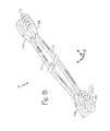
- FIG. 4 shows an apparatus constructed according to the present invention for impacting a skin of an aircraft as part of an electro-expulsive de-icing system onboard the aircraft. It is identified as an actuator 30 and it includes a first subassembly 31 having electrically conductive elements 31 A, 31 B, 31 C and a second subassembly 32 having electrically conductive elements 32 A, 32 B, 32 C.
- the electrically conductive elements of the first and second subassemblies 31 and 32 are connected in a multi-turn electrically conductive loop (i.e., a multi-turn coil) that carries movement-producing electric pulses, but it avoids the first and second encapsulated ends 23 and 24 of the prior art actuator 20 , thereby allowing the ends of first and second subassemblies 31 and 32 greater freedom of movement. As a result, actuator performance is improved and fatigue failure is avoided.
- a multi-turn electrically conductive loop i.e., a multi-turn coil
- the multiple conductive elements 31 A, 31 B, 31 C, 32 A, 32 B, and 32 C are interconnected by flexible connectors 33 , 34 , 35 , 36 , and 37 as illustrated, with the connectors 33 - 37 in FIG. 4 taking the form of jumper wires fabricated from lengths of stranded aircraft wire. Wires 38 and 39 connect the actuator to an onboard electronic control system (not shown in FIG. 4 ).
- the connectors 33 - 37 serve as means electrically interconnecting various ones of the terminal ends of the elements in order to thereby form the electrically conductive loop.
- the connectors 33 - 37 and the wires 38 and 39 are soldered or otherwise suitably connected to the ends of the elements 31 A through 32 C.
- the connectors 33 - 37 form U-shaped loops such that each U-shaped loop has two elongated leg portions connected by a mid portion, with the elongated leg portions functioning as lever arms that minimize the restrictive effect of the mid portion on relative movement of the first and second subassemblies 31 and 32 .
- FIG. 5 shows a second embodiment of an apparatus constructed according to the invention. It is identified as an actuator 40 , and it is similar in many respects to the actuator 30 . For convenience, reference numerals designating parts of the actuator 40 are increased by ten over those designating similar or related parts of the actuator 30 .
- the actuator 40 includes first and second subassemblies 41 and 42 , connectors 43 - 47 that interconnect the ends of multiple electrically conductive elements to form a loop, and wires 48 and 49 that connect the actuator 40 to an onboard electronic control system (not shown).
- the connectors 43 - 47 of the actuator 40 are sections of conductive ribbon in U-shaped configurations (e.g., similar in width and thickness to the ribbon composition of the electrically conductive elements of the first and second subassemblies 41 and 42 ).
- Each of the U-shaped connectors 43 - 47 includes two elongated legs connected to a mid portion, with the elongated leg portions functioning as lever arms that minimize the restrictive effect of the mid portion on relative movement of the first and second subassemblies 41 and 42 .
- FIG. 6 shows a third embodiment of an apparatus constructed according to the invention. It is identified as an actuator 50 , and it is similar in many respects to the actuator 40 . For convenience, reference numerals designating parts of the actuator 50 are increased by ten over those designating similar or related parts of the actuator 40 .
- the actuator 50 includes first and second subassemblies 51 and 52 , and connectors 53 - 55 that interconnect the ends of multiple electrically conductive elements to form a loop. Counterparts of the connectors 46 and 47 and the wires 48 and 49 are not shown in FIG. 6 for illustrative convenience.
- FIG. 6 also identifies a dimension 56 for the connector 55 .
- the dimension 56 is the distance by which the mid portions 53 C and 55 C of the connectors 53 and 55 are spaced from the element end it is connected to. The dimension 56 should be such that all stresses in the connector material are within acceptable material design limits.
- FIGS. 7 a and 7 b are enlarged cross sectional views of the actuator 50 installed between a skin 60 of an aircraft and an inner shell 61 (similar in some respects to the installation shown in FIG. 2 a ).
- FIG. 7 a illustrates an un-energized state of the actuator 50 in which no current pulse is flowing in the conductive loop
- FIG. 7 b illustrates an energized state of the actuator 50 in which a current pulse is flowing in the conductive loop.
- the first subassembly 51 is bonded by a bonding material 51 A to a web structure 51 B that is bonded by a bonding material 51 C to the skin 60 .
- the second subassembly 52 is bonded by a bonding material 52 A to the inner shell 61 .
- the first and second subassemblies 51 and 52 touch each other.
- the first and second subassemblies 51 and 52 move apart (e.g., by 0.08′′ to 0.50′′) as indicated by an arrow 62 to thereby cause ice-removing shock waves in the skin 60 .
- FIG. 8 shows a fourth embodiment of an actuator assembly constructed according to the invention. It is identified as an actuator 70 and it includes first and second subassemblies 71 and 72 such that each has four electrically conductive elements.
- the subassemblies 71 and 72 include encapsulated end portions 71 A, 71 B, 72 A, and 72 B connected by connectors, such as, for example, a connector 73 connecting two of the elements.
- the encapsulated end portions 71 A, 71 B, 72 A, and 72 B do not restrict movement of the subassemblies 71 and 72 relative to each other.
- FIGS. 9 , 10 , and 11 show actuators installed in the forward end portions of jet engine intakes.
- first and second actuators 81 and 82 installed in a forward portion 83 of a jet engine intake.
- the actuators 81 and 82 are generally similar to the actuators 30 , 40 , 50 and 70 already described, each having loop-forming first and second subassemblies arranged to move relative to each other for shock-wave-creating purposes without being restricted by encapsulated ends.
- the actuator 81 includes first and second subassemblies 81 A and 81 B, while the actuator 82 includes first and second subassemblies 82 A and 82 B.
- FIG. 9 first and second actuators 81 and 82 installed in a forward portion 83 of a jet engine intake.
- the actuators 81 and 82 are generally similar to the actuators 30 , 40 , 50 and 70 already described, each having loop-forming first and second subassemblies arranged to move relative to each other for shock-wave
- multiple actuators 84 are installed in a circularly shaped forward end portion 85 so that they extend axially; only one actuator 84 is labeled for illustrated convenience.
- multiple actuators 86 are shown diagrammatically installed in a circularly shaped forward end portion 87 so that they extend circumferentially, only one actuator 86 being labeled.
- FIG. 12 provides a diagrammatic review of the invention with reference to an electro-expulsive de-icing system 100 .
- the system 100 includes an actuator assembly having first and second electrically conductive subassemblies 101 and 102 that are mounted on an aircraft between an aircraft skin 103 and an aircraft support structure 104 , with the subassemblies 101 and 102 forming a multi-turn electrically conductive loop connected to an onboard electronic control system 105 .
- the control system 105 provides movement-producing electric current pulses to the actuator subassemblies 101 and 102 that cause the first and second subassemblies 101 and 102 to move apart as indicated by an arrow 106 in the X-Y plane, thereby forcefully pushing against the aircraft support structure 104 as indicated by an arrow 107 and against the aircraft skin 103 as indicated by an arrow 108 , doing so with a pulse of mechanical energy that creates ice-removing shock waves in the skin 103 .
- the first subassembly 101 (represented by a broken line at reference numeral 101 ) includes electrically conductive elements 101 A, 101 B, and 101 C extending along a first path 101 D in the X-Y plane that is perpendicular to the Y axis.
- the broken line is intended to indicate that the elements 101 A, 101 B, and 101 C are part of the first subassembly 101 .
- the second subassembly 102 includes electrically conductive elements 102 A, 102 B, and 102 C extending along a second path 102 D in the X-Y plane that is generally parallel to the first path 101 D.
- a current pulse flows in the elements 101 A, 101 B, and 101 C of the first subassembly 101 in a first direction indicated by an arrow 101 E as the current pulse flows in the elements 102 A, 102 B, and 102 C of the second subassembly 102 in an opposite second direction indicated by an arrow 102 E. That current flow results in the first and second assemblies moving apart for ice-removal purposes as indicated by the arrow 106 .
- the multi-turn electrically conductive loop (i.e., multi-turn coil) includes the following electrical connector and actuator elements: three connectors 111 , 112 , and 113 connecting respective ends 116 , 117 , and 118 of the respective elements 101 A, 101 B, and 101 C to respective ends 119 , 120 , and 121 of the respective elements 102 C, 102 B, and 102 A; and two opposing connectors 114 and 115 connecting respective opposing ends 122 and 123 of respective elements 101 B and 101 C to respective opposing ends 124 and 125 of elements 102 C and 102 B.
- Wires 128 and 129 connect ends 126 and 127 of the elements 101 A and 102 A to the control system 105 .
- the connectors provide a physical discontinuity in the multi-turn electrically conductive loop (i.e., a mechanical discontinuity as opposed to an electrical discontinuity) that enhances actuator operation by enabling a designer to specify connectors that are less restrictive to separation of loop subassemblies 101 and 102 than a physically continuous loop configuration and better suited to the precise configuration of the actuator.
- the mechanical discontinuity enables connector mechanical properties different than the mechanical properties of the rest of the electrically conductive loop; a designer chooses the connector mechanical properties to be less restrictive and thereby to enhance actuator operation.
- the connectors 111 though 115 are jumpers in the form of flexible loops as depicted by the connector 130 in FIGS. 13 a and 13 b .
- the connector 130 includes first and second elongated legs 130 A and 130 B and mid portion 130 C.
- the legs 130 A and 130 B extend from the mid portion 130 C a distance indicated by a dimension 131 in FIG. 13 a , while the mid portion 130 C forms a circular arc that extends toward the legs a distance indicated by a dimension 132 in FIG. 13 a .
- the length of the legs 130 a and 130 B combine with the size of the mid portion 130 C to result in the mid portion 130 C being located a distance from the elements to which it is connected that is indicated by a dimension 133 in FIG. 13 a.
- the dimension 133 is at least twice the distance that the first and second subassemblies 101 and 102 to which the connector 130 is connected move apart in operation in order that the connector 130 is sufficiently flexible not to restrict such movement significantly.
- the actuator to which the connector 130 is connected is in an un-energized state, the connector is in a relaxed state as shown in FIG. 13 a , with the legs separated as indicated by a dimension 134 in FIG. 13 a .
- the connector 130 deforms resiliently to the deformed configuration shown in FIG. 13 b as depicted by arrows 135 and 136 in FIG. 13 b.
- the invention provides an electro-expulsive de-icing actuator that alleviates performance and fatigue failure concerns of the prior art.
- exemplary embodiments have been shown and described, one of ordinary skill in the art may make many changes, modifications, and substitutions without necessarily departing from the spirit and scope of the invention.
- the system and actuators may be used for ice-removal applications other than in-flight aircraft de-icing.
- the electro-expulsive de-icing structure (EEDS) can be fabricated in circular configuration for applications such as ship board communication antennas, bridge cabling, and so forth, and in a flat panel configuration for applications such as river way locks or ship board superstructure and so forth.
- EEDS electro-expulsive de-icing structure
- the connector stress can be reduced by lowering that component of magnetic actuator force generated within the connectors themselves.
- This deliberate reduction in connector-produced actuation force is accomplished by dispersing the force-generating ampere-turns density and by increasing the length of the distance “d” between mutually opposed current paths as described below (see FIG. 14 ). This is not a change in the invention as it has been conceived, but a recognition of an additional advantage and intent of already existing features of the invention.
- connectors In line with the foregoing, it is further desirable for purposes of reducing connector stress that the connectors generate low mechanical actuation force per unit length of conductor than the respective actuator elements to which they are attached.
- Connectors comprise among other features of their construction, which may be optional or necessary features of their construction, depending on the particular connector, which render them potentially vulnerable to reliability problems if subjected to repetitive mechanical stresses of the type produced by the prior art in which mechanical coupling of actuator movement induces undesirable stress and fatigue into the connectors themselves.
- the invention provides relief from the effects of mechanical coupling between actuator members and connectors, that same electrical current and magnetic force which gives rise to mechanical displacement in the actuator members likewise produces a mechanical force and stress within the connectors themselves.
- the said mechanical force generated per unit length of connector would be roughly the same as that mechanical force per unit length generated within the actuator, were the connector of same geometry and dimensional displacement between opposing current paths as the actuator itself.
- the practical mechanical force generated within the connector may be in fact larger per unit length than that of the actuator, since the connector region constrains the displacement d during actuation through the restriction of conductor movement near the bends within the connector.
- FIG. 14 it shows greater actuation force per unit length within a connector of prior art.
- the connector designs in the foregoing description in addition to providing good mechanical stress relief, reduce the actuation force generated within the connector lead wires themselves as will be described below. This is accomplished in the embodiment by dispersing the coil current through connectors configured as wide strips or as individual widely separated wires, thus reducing the undesired connector wire-induced actuation force.
- FIG. 16 a and FIG. 16 b show lower actuation force per unit length within the invented connector dispersal of actuator current into wide strips ( FIG. 16 a ) and into multiple separated conductors ( FIG. 16 b ).
- Prior art actuators of such type have connectors extending in a direction substantially parallel with and extending in an extension substantially further along path P, with the connectors contained in a substantially tight bundle within the confines of extended path P such that upon generation of actuation force F the connectors need to draw inward in a contraction along path P in order to permit the movement apart of the actuator members along a path of the direction of force F.
- One form of the invention has a type of connectors fabricated and installed in such a way as to extend in a direction substantially divergent from path P so that the connectors relieve the stress of actuator expansion in the direction of force F without drawing the connectors inward along path P.
- This looks like loops of wire, or like right angle wide flexible strips, per FIGS. 4 and 6 .
- Another form of the invention has another type of connectors fabricated and installed in such a way as to extend in a direction along path P in a substantially loose bundle within the confines of path P; that is, the individual connector loops may spread out along path P such that the connectors relieve the stress of actuator expansion in the direction of force F without drawing all of the connectors in a bundle together inward along path P at the same rate.
Landscapes
- Engineering & Computer Science (AREA)
- Mechanical Engineering (AREA)
- Aviation & Aerospace Engineering (AREA)
- Electromagnets (AREA)
- Details Of Connecting Devices For Male And Female Coupling (AREA)
- Fluid-Pressure Circuits (AREA)
- Actuator (AREA)
Abstract
Description
F m =I 2 ×N 2×μ0 /d, where:
-
- Fm is the force in Newtons per meter of actuator wire length
- I is the current in the wires in Amperes
- N is the number of paralleled conductors in each leg
- d is the separation distance in meters
- μ0 is the electromagnetic constant =1.26×10⁻⁷
F m2 =I 2×¼×N 2×μ0 /d=F m/4
F=2×F m/4=F m/2
Claims (32)
Priority Applications (11)
| Application Number | Priority Date | Filing Date | Title |
|---|---|---|---|
| US12/658,304 US9108735B2 (en) | 2009-05-13 | 2010-02-05 | Electro-expulsive de-icing system for aircraft and other applications |
| PCT/US2010/001408 WO2011002481A2 (en) | 2009-05-13 | 2010-05-12 | Electro-expulsive de-icing system for aircraft and other applications |
| BRPI1013510-3A BRPI1013510A2 (en) | 2009-05-13 | 2010-05-12 | ELECTRO-EXPULSIVE DEFROST SYSTEM FOR AIRPLANES AND OTHER APPLICATIONS |
| CN201080026628.9A CN102458990B (en) | 2009-05-13 | 2010-05-12 | Electricity for aircraft and other application is got rid of deicing system |
| JP2012510794A JP5871794B2 (en) | 2009-05-13 | 2010-05-12 | Articles and methods with electrical deicing devices for aircraft and other applications |
| CA2761626A CA2761626C (en) | 2009-05-13 | 2010-05-12 | Electro-expulsive de-icing system for aircraft and other applications |
| EP10794474.6A EP2429898B1 (en) | 2009-05-13 | 2010-05-12 | Electro-expulsive de-icing system for aircraft and other applications |
| IL216273A IL216273A (en) | 2009-05-13 | 2011-11-10 | Electro-expulsive de-icing system for aircraft and other applications |
| US13/790,065 US20130187006A1 (en) | 2009-05-13 | 2013-03-08 | Electro-Expulsive De-Icing System for Aircraft and Other Applications |
| JP2015229095A JP2016064818A (en) | 2009-05-13 | 2015-11-24 | Electro-expulsive de-icing system for aircraft and other applications |
| US15/064,957 US20160185458A1 (en) | 2009-05-13 | 2016-03-09 | Electro-Expulsive De-Icing System for Aircraft and Other Applications |
Applications Claiming Priority (2)
| Application Number | Priority Date | Filing Date | Title |
|---|---|---|---|
| US21610709P | 2009-05-13 | 2009-05-13 | |
| US12/658,304 US9108735B2 (en) | 2009-05-13 | 2010-02-05 | Electro-expulsive de-icing system for aircraft and other applications |
Related Child Applications (1)
| Application Number | Title | Priority Date | Filing Date |
|---|---|---|---|
| US13/790,065 Continuation US20130187006A1 (en) | 2009-05-13 | 2013-03-08 | Electro-Expulsive De-Icing System for Aircraft and Other Applications |
Publications (2)
| Publication Number | Publication Date |
|---|---|
| US20100288882A1 US20100288882A1 (en) | 2010-11-18 |
| US9108735B2 true US9108735B2 (en) | 2015-08-18 |
Family
ID=43067734
Family Applications (3)
| Application Number | Title | Priority Date | Filing Date |
|---|---|---|---|
| US12/658,304 Active 2033-06-23 US9108735B2 (en) | 2009-05-13 | 2010-02-05 | Electro-expulsive de-icing system for aircraft and other applications |
| US13/790,065 Abandoned US20130187006A1 (en) | 2009-05-13 | 2013-03-08 | Electro-Expulsive De-Icing System for Aircraft and Other Applications |
| US15/064,957 Abandoned US20160185458A1 (en) | 2009-05-13 | 2016-03-09 | Electro-Expulsive De-Icing System for Aircraft and Other Applications |
Family Applications After (2)
| Application Number | Title | Priority Date | Filing Date |
|---|---|---|---|
| US13/790,065 Abandoned US20130187006A1 (en) | 2009-05-13 | 2013-03-08 | Electro-Expulsive De-Icing System for Aircraft and Other Applications |
| US15/064,957 Abandoned US20160185458A1 (en) | 2009-05-13 | 2016-03-09 | Electro-Expulsive De-Icing System for Aircraft and Other Applications |
Country Status (8)
| Country | Link |
|---|---|
| US (3) | US9108735B2 (en) |
| EP (1) | EP2429898B1 (en) |
| JP (2) | JP5871794B2 (en) |
| CN (1) | CN102458990B (en) |
| BR (1) | BRPI1013510A2 (en) |
| CA (1) | CA2761626C (en) |
| IL (1) | IL216273A (en) |
| WO (1) | WO2011002481A2 (en) |
Cited By (3)
| Publication number | Priority date | Publication date | Assignee | Title |
|---|---|---|---|---|
| US20150303369A1 (en) * | 2012-11-08 | 2015-10-22 | Saab Ab | De-icing arrangement and method for de-icing a structural element |
| US9889940B2 (en) | 2016-02-16 | 2018-02-13 | Peter Lenkey | Deicing apparatuses comprising at least one standoff |
| US20210129998A1 (en) * | 2018-03-29 | 2021-05-06 | Gkn Aerospace Services Limited | Ice removal system |
Families Citing this family (11)
| Publication number | Priority date | Publication date | Assignee | Title |
|---|---|---|---|---|
| US9108735B2 (en) * | 2009-05-13 | 2015-08-18 | Tmc Aerospace, Inc. | Electro-expulsive de-icing system for aircraft and other applications |
| FR2961789B1 (en) * | 2010-06-24 | 2012-07-20 | Eurocopter France | METHOD FOR AVOIDING THE CLOSURE OF A GRID, GRID AND AIR INTAKE USING SUCH A METHOD |
| US20130228653A1 (en) * | 2011-11-17 | 2013-09-05 | Spirit Aerosystems, Inc. | Electrothermal and electro expulsive hybrid ice protection system for engine inlet |
| US20150191249A1 (en) * | 2012-08-01 | 2015-07-09 | Parviz Acquisitions Llc | Flexible electro-mechanical actuator and flexing bodies |
| US20140252172A1 (en) * | 2013-03-05 | 2014-09-11 | Parviz Acquisitions Llc | Single surface electro-mechanical actuator assembly |
| GB201306674D0 (en) * | 2013-04-12 | 2013-05-29 | Rolls Royce Plc | Rigid Raft for a Gas Turbine Engine |
| US10155373B2 (en) * | 2015-10-16 | 2018-12-18 | Quest Integrated, Llc | Printed multifunctional skin for aerodynamic structures, and associated systems and methods |
| US10464680B2 (en) * | 2016-08-30 | 2019-11-05 | The Boeing Company | Electrically conductive materials for heating and deicing airfoils |
| CN106516125A (en) * | 2016-12-02 | 2017-03-22 | 武汉航空仪表有限责任公司 | Circular coil structure for electro-impulse deicing |
| US11477888B2 (en) * | 2018-10-08 | 2022-10-18 | Quest Integrated, Llc | Printed multifunctional skin for aerodynamic structures and associated systems and methods |
| CN111452951B (en) * | 2020-04-14 | 2022-01-14 | 山东大学 | Wing deicer and wing comprising same |
Citations (37)
| Publication number | Priority date | Publication date | Assignee | Title |
|---|---|---|---|---|
| US3809341A (en) * | 1972-11-14 | 1974-05-07 | I Levin | Device for removing ice from surfaces of thin-walled structures |
| US4678144A (en) * | 1984-10-26 | 1987-07-07 | Simmonds Precision | Electro-impulse de-icing system for aircraft |
| US4690353A (en) * | 1985-05-31 | 1987-09-01 | The United States Of America As Represented By The Administrator Of The National Aeronautics And Space Administration | Electro-expulsive separation system |
| US4872644A (en) * | 1985-12-23 | 1989-10-10 | Papapetros Peter A | Motor vehicle servicing tool |
| US4875644A (en) * | 1988-10-14 | 1989-10-24 | The B. F. Goodrich Company | Electro-repulsive separation system for deicing |
| US4894569A (en) * | 1988-06-13 | 1990-01-16 | Dataproducts New England, Inc. | Electro-expulsive separation apparatus |
| US4982121A (en) * | 1988-06-13 | 1991-01-01 | Dataproducts New England, Inc. | Expulsive separation apparatus |
| US5022612A (en) * | 1989-03-13 | 1991-06-11 | Berson Berle D | Electro-expulsive boots |
| US5074497A (en) | 1989-08-28 | 1991-12-24 | The B. F. Goodrich Company | Deicer for aircraft |
| US5107154A (en) * | 1990-12-19 | 1992-04-21 | Dataproducts New England, Incorporated | Electro-expulsive apparatus and method |
| US5129598A (en) * | 1989-12-22 | 1992-07-14 | B. F. Goodrich Co. | Attachable electro-impulse de-icer |
| US5142767A (en) * | 1989-11-15 | 1992-09-01 | Bf Goodrich Company | Method of manufacturing a planar coil construction |
| US5143325A (en) * | 1991-01-03 | 1992-09-01 | Electroimpact, Inc. | Electromagnetic repulsion system for removing contaminants such as ice from the surfaces of aircraft and other objects |
| US5152480A (en) * | 1989-11-15 | 1992-10-06 | The B. F. Goodrich Company | Planar coil construction |
| US5248116A (en) | 1992-02-07 | 1993-09-28 | The B. F. Goodrich Company | Airfoil with integral de-icer using overlapped tubes |
| US5272400A (en) | 1992-05-26 | 1993-12-21 | Dataproducts New England, Inc. | Expulsive ice detector |
| US5288355A (en) | 1989-11-06 | 1994-02-22 | The B.F. Goodrich Company | Structural airfoil having integral expulsive system |
| US5314145A (en) | 1992-12-30 | 1994-05-24 | The B.F. Goodrich Company | Compressible nose dynamic de-icer |
| US5326051A (en) * | 1992-06-30 | 1994-07-05 | The B. F. Goodrich Company | Electro-expulsive deicing system having circuit board expulsive members |
| US5346160A (en) * | 1992-06-30 | 1994-09-13 | The B. F. Goodrich Company | Electro-expulsive deicing system having fail safe conductive bridge means |
| US5429327A (en) * | 1993-10-22 | 1995-07-04 | The B.F. Goodrich Company | Electro-impulse de-icer |
| US5544845A (en) | 1993-10-01 | 1996-08-13 | The B.F. Goodrich Company | Polyurethane deicer |
| US5547150A (en) * | 1994-03-22 | 1996-08-20 | The B.F. Goodrich Company | Mechanical deicer having decoupled skin segments |
| US5553815A (en) * | 1994-04-07 | 1996-09-10 | The B. F. Goodrich Company | De-icer adapted for installment on the inner surface of a structural member |
| US5553814A (en) | 1992-12-30 | 1996-09-10 | The B.F. Goodrich Company | Skin for a deicer |
| US5584450A (en) | 1992-07-21 | 1996-12-17 | The B. F. Goodrich Company | Metal clad electro-expulsive deicer with segmented elements |
| US5657952A (en) * | 1995-07-31 | 1997-08-19 | Dynamic Controls Hs, Inc. | Electro-expulsive de-icing apparatus and method of use |
| US5686003A (en) | 1994-06-06 | 1997-11-11 | Innovative Dynamics, Inc. | Shape memory alloy de-icing technology |
| US5782435A (en) * | 1995-05-24 | 1998-07-21 | Cox & Company, Inc. | Electro-magnetic expulsion de-icing system |
| US5921502A (en) | 1996-06-19 | 1999-07-13 | Cox & Company, Inc. | Hybrid ice-protection system for use on roughness-sensitive airfoils |
| US6207939B1 (en) | 1997-08-01 | 2001-03-27 | Hydro-Quebec | Device and method for de-icing an elongated structural element |
| US6283411B1 (en) * | 1998-01-21 | 2001-09-04 | The B.F. Goodrich Company | Hybrid deicer with element sequence control |
| US6684647B2 (en) | 1998-06-15 | 2004-02-03 | The Trustees Of Dartmouth College | High-frequency melting of ice between freezer packages |
| US6870139B2 (en) | 2002-02-11 | 2005-03-22 | The Trustees Of Dartmouth College | Systems and methods for modifying an ice-to-object interface |
| US7087876B2 (en) * | 1998-06-15 | 2006-08-08 | The Trustees Of Dartmouth College | High-frequency melting of interfacial ice |
| US7164100B2 (en) | 1998-06-15 | 2007-01-16 | The Trustees Of Dartmouth College | High-frequency de-icing of cableways |
| US20130187006A1 (en) | 2009-05-13 | 2013-07-25 | Ice Management Systems | Electro-Expulsive De-Icing System for Aircraft and Other Applications |
Family Cites Families (2)
| Publication number | Priority date | Publication date | Assignee | Title |
|---|---|---|---|---|
| JPS4983198A (en) * | 1972-12-13 | 1974-08-09 | ||
| CN1027531C (en) * | 1989-11-06 | 1995-02-01 | B·F·谷德里奇公司 | Structural airfoil with integral deicing device |
-
2010
- 2010-02-05 US US12/658,304 patent/US9108735B2/en active Active
- 2010-05-12 EP EP10794474.6A patent/EP2429898B1/en active Active
- 2010-05-12 CN CN201080026628.9A patent/CN102458990B/en not_active Expired - Fee Related
- 2010-05-12 BR BRPI1013510-3A patent/BRPI1013510A2/en not_active Application Discontinuation
- 2010-05-12 CA CA2761626A patent/CA2761626C/en not_active Expired - Fee Related
- 2010-05-12 WO PCT/US2010/001408 patent/WO2011002481A2/en active Application Filing
- 2010-05-12 JP JP2012510794A patent/JP5871794B2/en not_active Expired - Fee Related
-
2011
- 2011-11-10 IL IL216273A patent/IL216273A/en active IP Right Grant
-
2013
- 2013-03-08 US US13/790,065 patent/US20130187006A1/en not_active Abandoned
-
2015
- 2015-11-24 JP JP2015229095A patent/JP2016064818A/en active Pending
-
2016
- 2016-03-09 US US15/064,957 patent/US20160185458A1/en not_active Abandoned
Patent Citations (41)
| Publication number | Priority date | Publication date | Assignee | Title |
|---|---|---|---|---|
| US3809341A (en) * | 1972-11-14 | 1974-05-07 | I Levin | Device for removing ice from surfaces of thin-walled structures |
| US4678144A (en) * | 1984-10-26 | 1987-07-07 | Simmonds Precision | Electro-impulse de-icing system for aircraft |
| US4690353A (en) * | 1985-05-31 | 1987-09-01 | The United States Of America As Represented By The Administrator Of The National Aeronautics And Space Administration | Electro-expulsive separation system |
| US4872644A (en) * | 1985-12-23 | 1989-10-10 | Papapetros Peter A | Motor vehicle servicing tool |
| US4982121A (en) * | 1988-06-13 | 1991-01-01 | Dataproducts New England, Inc. | Expulsive separation apparatus |
| US4894569A (en) * | 1988-06-13 | 1990-01-16 | Dataproducts New England, Inc. | Electro-expulsive separation apparatus |
| US4875644A (en) * | 1988-10-14 | 1989-10-24 | The B. F. Goodrich Company | Electro-repulsive separation system for deicing |
| US5022612A (en) * | 1989-03-13 | 1991-06-11 | Berson Berle D | Electro-expulsive boots |
| US5074497A (en) | 1989-08-28 | 1991-12-24 | The B. F. Goodrich Company | Deicer for aircraft |
| US5288355A (en) | 1989-11-06 | 1994-02-22 | The B.F. Goodrich Company | Structural airfoil having integral expulsive system |
| US5142767A (en) * | 1989-11-15 | 1992-09-01 | Bf Goodrich Company | Method of manufacturing a planar coil construction |
| US5152480A (en) * | 1989-11-15 | 1992-10-06 | The B. F. Goodrich Company | Planar coil construction |
| US5129598A (en) * | 1989-12-22 | 1992-07-14 | B. F. Goodrich Co. | Attachable electro-impulse de-icer |
| USRE38024E1 (en) * | 1989-12-22 | 2003-03-11 | Goodrich Corporation | Attachable electro-impulse de-icer |
| US5107154A (en) * | 1990-12-19 | 1992-04-21 | Dataproducts New England, Incorporated | Electro-expulsive apparatus and method |
| US5143325A (en) * | 1991-01-03 | 1992-09-01 | Electroimpact, Inc. | Electromagnetic repulsion system for removing contaminants such as ice from the surfaces of aircraft and other objects |
| US5143325B1 (en) * | 1991-01-03 | 2000-09-05 | Electroimpact Inc | Electromagnetic repulsion system for removing contaminants such as ice from the surface of aircraft and other objects |
| US5248116A (en) | 1992-02-07 | 1993-09-28 | The B. F. Goodrich Company | Airfoil with integral de-icer using overlapped tubes |
| US5272400A (en) | 1992-05-26 | 1993-12-21 | Dataproducts New England, Inc. | Expulsive ice detector |
| US5326051A (en) * | 1992-06-30 | 1994-07-05 | The B. F. Goodrich Company | Electro-expulsive deicing system having circuit board expulsive members |
| US5346160A (en) * | 1992-06-30 | 1994-09-13 | The B. F. Goodrich Company | Electro-expulsive deicing system having fail safe conductive bridge means |
| US5584450A (en) | 1992-07-21 | 1996-12-17 | The B. F. Goodrich Company | Metal clad electro-expulsive deicer with segmented elements |
| US5314145A (en) | 1992-12-30 | 1994-05-24 | The B.F. Goodrich Company | Compressible nose dynamic de-icer |
| US5553814A (en) | 1992-12-30 | 1996-09-10 | The B.F. Goodrich Company | Skin for a deicer |
| US5544845A (en) | 1993-10-01 | 1996-08-13 | The B.F. Goodrich Company | Polyurethane deicer |
| US5429327A (en) * | 1993-10-22 | 1995-07-04 | The B.F. Goodrich Company | Electro-impulse de-icer |
| US5547150A (en) * | 1994-03-22 | 1996-08-20 | The B.F. Goodrich Company | Mechanical deicer having decoupled skin segments |
| US5553815A (en) * | 1994-04-07 | 1996-09-10 | The B. F. Goodrich Company | De-icer adapted for installment on the inner surface of a structural member |
| US5686003A (en) | 1994-06-06 | 1997-11-11 | Innovative Dynamics, Inc. | Shape memory alloy de-icing technology |
| US5782435A (en) * | 1995-05-24 | 1998-07-21 | Cox & Company, Inc. | Electro-magnetic expulsion de-icing system |
| US6102333A (en) | 1995-05-24 | 2000-08-15 | Innovative Dynamics, Inc. | Electro-magnetic expulsion de-icing system |
| US5657952A (en) * | 1995-07-31 | 1997-08-19 | Dynamic Controls Hs, Inc. | Electro-expulsive de-icing apparatus and method of use |
| US5921502A (en) | 1996-06-19 | 1999-07-13 | Cox & Company, Inc. | Hybrid ice-protection system for use on roughness-sensitive airfoils |
| US6196500B1 (en) | 1996-06-19 | 2001-03-06 | Cox & Company, Inc. | Hybrid ice protection system for use on roughness-sensitive airfoils |
| US6207939B1 (en) | 1997-08-01 | 2001-03-27 | Hydro-Quebec | Device and method for de-icing an elongated structural element |
| US6283411B1 (en) * | 1998-01-21 | 2001-09-04 | The B.F. Goodrich Company | Hybrid deicer with element sequence control |
| US6684647B2 (en) | 1998-06-15 | 2004-02-03 | The Trustees Of Dartmouth College | High-frequency melting of ice between freezer packages |
| US7087876B2 (en) * | 1998-06-15 | 2006-08-08 | The Trustees Of Dartmouth College | High-frequency melting of interfacial ice |
| US7164100B2 (en) | 1998-06-15 | 2007-01-16 | The Trustees Of Dartmouth College | High-frequency de-icing of cableways |
| US6870139B2 (en) | 2002-02-11 | 2005-03-22 | The Trustees Of Dartmouth College | Systems and methods for modifying an ice-to-object interface |
| US20130187006A1 (en) | 2009-05-13 | 2013-07-25 | Ice Management Systems | Electro-Expulsive De-Icing System for Aircraft and Other Applications |
Non-Patent Citations (1)
| Title |
|---|
| Supplementary European Search Report and Opinion for Application No. EP 10794474, International Filing Date May 21, 2010, Search Completed Sep. 13, 2013, Mailed Sep. 20, 2013, 5 pgs. |
Cited By (7)
| Publication number | Priority date | Publication date | Assignee | Title |
|---|---|---|---|---|
| US20150303369A1 (en) * | 2012-11-08 | 2015-10-22 | Saab Ab | De-icing arrangement and method for de-icing a structural element |
| US9882114B2 (en) * | 2012-11-08 | 2018-01-30 | Saab Ab | De-icing arrangement and method for de-icing a structural element |
| US9889940B2 (en) | 2016-02-16 | 2018-02-13 | Peter Lenkey | Deicing apparatuses comprising at least one standoff |
| US10000290B2 (en) | 2016-02-16 | 2018-06-19 | Peter Lenkey | Electro-expulsive deicing apparatuses comprising at least one standoff |
| US20180237145A1 (en) * | 2016-02-16 | 2018-08-23 | Peter Lenkey | Deicing Apparatuses Comprising at least one standoff |
| US20210129998A1 (en) * | 2018-03-29 | 2021-05-06 | Gkn Aerospace Services Limited | Ice removal system |
| US12030648B2 (en) * | 2018-03-29 | 2024-07-09 | Gkn Aerospace Services Limited | Ice removal system |
Also Published As
| Publication number | Publication date |
|---|---|
| WO2011002481A3 (en) | 2011-02-24 |
| US20130187006A1 (en) | 2013-07-25 |
| CN102458990B (en) | 2016-05-25 |
| US20160185458A1 (en) | 2016-06-30 |
| EP2429898A4 (en) | 2013-10-23 |
| CA2761626A1 (en) | 2011-01-06 |
| JP2012526705A (en) | 2012-11-01 |
| BRPI1013510A2 (en) | 2021-10-05 |
| CA2761626C (en) | 2016-11-08 |
| WO2011002481A2 (en) | 2011-01-06 |
| IL216273A0 (en) | 2012-01-31 |
| CN102458990A (en) | 2012-05-16 |
| EP2429898B1 (en) | 2016-04-13 |
| IL216273A (en) | 2016-07-31 |
| US20100288882A1 (en) | 2010-11-18 |
| JP2016064818A (en) | 2016-04-28 |
| JP5871794B2 (en) | 2016-03-01 |
| EP2429898A2 (en) | 2012-03-21 |
Similar Documents
| Publication | Publication Date | Title |
|---|---|---|
| US9108735B2 (en) | Electro-expulsive de-icing system for aircraft and other applications | |
| US10368401B2 (en) | Multi-functional composite structures | |
| US8937254B2 (en) | Apparatus and method for an aircraft conductor sandwich assembly embedded to an aircraft structure | |
| US5143325A (en) | Electromagnetic repulsion system for removing contaminants such as ice from the surfaces of aircraft and other objects | |
| US8031458B2 (en) | Current return network | |
| US20160343467A1 (en) | Multi-functional composite structures | |
| KR101321863B1 (en) | Hybrid fabric materials, and structural components incorporating same | |
| JP2012526705A5 (en) | ||
| US20140252172A1 (en) | Single surface electro-mechanical actuator assembly | |
| US10596983B2 (en) | Wire harness | |
| EP1450377A2 (en) | Structurally integrated wire and associated fabrication method | |
| US5346160A (en) | Electro-expulsive deicing system having fail safe conductive bridge means | |
| US20170028947A1 (en) | Vehicle fairing including an electrical routing | |
| US5326051A (en) | Electro-expulsive deicing system having circuit board expulsive members | |
| US9125296B2 (en) | Electrical harness | |
| CN109835275A (en) | Flat distribution structure | |
| CN114724749A (en) | Flexible wiring member | |
| US20150191249A1 (en) | Flexible electro-mechanical actuator and flexing bodies | |
| DK202370156A1 (en) | A flexible electrical conductor | |
| US11855515B2 (en) | Multilayer neutral bus | |
| WO2011094630A1 (en) | Electrical cable having return wires positioned between force wires | |
| KR20240125583A (en) | Printed wiring boards and coil devices | |
| CN118984518A (en) | Electrostatic discharge system and transportation | |
| JP2013027265A (en) | Flat cable assembly |
Legal Events
| Date | Code | Title | Description |
|---|---|---|---|
| AS | Assignment |
Owner name: ICE MANAGEMENT SYSTEMS, INC., CALIFORNIA Free format text: ASSIGNMENT OF ASSIGNORS INTEREST;ASSIGNORS:OLSON, RICHARD ALEXANDER;BRIDGEFORD, MARK RONALD;REEL/FRAME:024041/0095 Effective date: 20100301 |
|
| AS | Assignment |
Owner name: PARVIZ ACQUISITIONS, LLC, CALIFORNIA Free format text: ASSIGNMENT OF ASSIGNORS INTEREST;ASSIGNOR:ICE MANAGEMENT SYSTEMS, INC.;REEL/FRAME:032821/0247 Effective date: 20140120 |
|
| AS | Assignment |
Owner name: TMC AEROSPACE, INC., CALIFORNIA Free format text: ASSIGNMENT OF ASSIGNORS INTEREST;ASSIGNOR:PARVIZ ACQUISITIONS, LLC;REEL/FRAME:035298/0165 Effective date: 20150303 |
|
| STCF | Information on status: patent grant |
Free format text: PATENTED CASE |
|
| MAFP | Maintenance fee payment |
Free format text: PAYMENT OF MAINTENANCE FEE, 4TH YR, SMALL ENTITY (ORIGINAL EVENT CODE: M2551); ENTITY STATUS OF PATENT OWNER: SMALL ENTITY Year of fee payment: 4 |
|
| MAFP | Maintenance fee payment |
Free format text: PAYMENT OF MAINTENANCE FEE, 8TH YR, SMALL ENTITY (ORIGINAL EVENT CODE: M2552); ENTITY STATUS OF PATENT OWNER: SMALL ENTITY Year of fee payment: 8 |