US9099926B2 - System and method for connecting the midpoint of a dual-DC bus to ground - Google Patents
System and method for connecting the midpoint of a dual-DC bus to ground Download PDFInfo
- Publication number
- US9099926B2 US9099926B2 US13/649,963 US201213649963A US9099926B2 US 9099926 B2 US9099926 B2 US 9099926B2 US 201213649963 A US201213649963 A US 201213649963A US 9099926 B2 US9099926 B2 US 9099926B2
- Authority
- US
- United States
- Prior art keywords
- power
- dual
- active rectifier
- bus
- capacitor
- Prior art date
- Legal status (The legal status is an assumption and is not a legal conclusion. Google has not performed a legal analysis and makes no representation as to the accuracy of the status listed.)
- Active, expires
Links
- 238000000034 method Methods 0.000 title claims description 9
- 239000003990 capacitor Substances 0.000 claims description 24
- 238000001914 filtration Methods 0.000 claims description 2
- 238000010586 diagram Methods 0.000 description 6
- 230000002457 bidirectional effect Effects 0.000 description 1
- 238000013016 damping Methods 0.000 description 1
- 239000000463 material Substances 0.000 description 1
- 238000012986 modification Methods 0.000 description 1
- 230000004048 modification Effects 0.000 description 1
- 230000007935 neutral effect Effects 0.000 description 1
- 230000001052 transient effect Effects 0.000 description 1
Images


Classifications
-
- H—ELECTRICITY
- H02—GENERATION; CONVERSION OR DISTRIBUTION OF ELECTRIC POWER
- H02M—APPARATUS FOR CONVERSION BETWEEN AC AND AC, BETWEEN AC AND DC, OR BETWEEN DC AND DC, AND FOR USE WITH MAINS OR SIMILAR POWER SUPPLY SYSTEMS; CONVERSION OF DC OR AC INPUT POWER INTO SURGE OUTPUT POWER; CONTROL OR REGULATION THEREOF
- H02M7/00—Conversion of AC power input into DC power output; Conversion of DC power input into AC power output
- H02M7/02—Conversion of AC power input into DC power output without possibility of reversal
- H02M7/04—Conversion of AC power input into DC power output without possibility of reversal by static converters
- H02M7/12—Conversion of AC power input into DC power output without possibility of reversal by static converters using discharge tubes with control electrode or semiconductor devices with control electrode
- H02M7/21—Conversion of AC power input into DC power output without possibility of reversal by static converters using discharge tubes with control electrode or semiconductor devices with control electrode using devices of a triode or transistor type requiring continuous application of a control signal
- H02M7/217—Conversion of AC power input into DC power output without possibility of reversal by static converters using discharge tubes with control electrode or semiconductor devices with control electrode using devices of a triode or transistor type requiring continuous application of a control signal using semiconductor devices only
- H02M7/219—Conversion of AC power input into DC power output without possibility of reversal by static converters using discharge tubes with control electrode or semiconductor devices with control electrode using devices of a triode or transistor type requiring continuous application of a control signal using semiconductor devices only in a bridge configuration
-
- H—ELECTRICITY
- H02—GENERATION; CONVERSION OR DISTRIBUTION OF ELECTRIC POWER
- H02M—APPARATUS FOR CONVERSION BETWEEN AC AND AC, BETWEEN AC AND DC, OR BETWEEN DC AND DC, AND FOR USE WITH MAINS OR SIMILAR POWER SUPPLY SYSTEMS; CONVERSION OF DC OR AC INPUT POWER INTO SURGE OUTPUT POWER; CONTROL OR REGULATION THEREOF
- H02M1/00—Details of apparatus for conversion
- H02M1/12—Arrangements for reducing harmonics from AC input or output
- H02M1/126—Arrangements for reducing harmonics from AC input or output using passive filters
-
- H—ELECTRICITY
- H02—GENERATION; CONVERSION OR DISTRIBUTION OF ELECTRIC POWER
- H02M—APPARATUS FOR CONVERSION BETWEEN AC AND AC, BETWEEN AC AND DC, OR BETWEEN DC AND DC, AND FOR USE WITH MAINS OR SIMILAR POWER SUPPLY SYSTEMS; CONVERSION OF DC OR AC INPUT POWER INTO SURGE OUTPUT POWER; CONTROL OR REGULATION THEREOF
- H02M7/00—Conversion of AC power input into DC power output; Conversion of DC power input into AC power output
- H02M7/42—Conversion of DC power input into AC power output without possibility of reversal
-
- H—ELECTRICITY
- H02—GENERATION; CONVERSION OR DISTRIBUTION OF ELECTRIC POWER
- H02M—APPARATUS FOR CONVERSION BETWEEN AC AND AC, BETWEEN AC AND DC, OR BETWEEN DC AND DC, AND FOR USE WITH MAINS OR SIMILAR POWER SUPPLY SYSTEMS; CONVERSION OF DC OR AC INPUT POWER INTO SURGE OUTPUT POWER; CONTROL OR REGULATION THEREOF
- H02M1/00—Details of apparatus for conversion
- H02M1/12—Arrangements for reducing harmonics from AC input or output
- H02M1/123—Suppression of common mode voltage or current
-
- H—ELECTRICITY
- H02—GENERATION; CONVERSION OR DISTRIBUTION OF ELECTRIC POWER
- H02M—APPARATUS FOR CONVERSION BETWEEN AC AND AC, BETWEEN AC AND DC, OR BETWEEN DC AND DC, AND FOR USE WITH MAINS OR SIMILAR POWER SUPPLY SYSTEMS; CONVERSION OF DC OR AC INPUT POWER INTO SURGE OUTPUT POWER; CONTROL OR REGULATION THEREOF
- H02M1/00—Details of apparatus for conversion
- H02M1/44—Circuits or arrangements for compensating for electromagnetic interference in converters or inverters
-
- H02M2001/123—
-
- Y—GENERAL TAGGING OF NEW TECHNOLOGICAL DEVELOPMENTS; GENERAL TAGGING OF CROSS-SECTIONAL TECHNOLOGIES SPANNING OVER SEVERAL SECTIONS OF THE IPC; TECHNICAL SUBJECTS COVERED BY FORMER USPC CROSS-REFERENCE ART COLLECTIONS [XRACs] AND DIGESTS
- Y02—TECHNOLOGIES OR APPLICATIONS FOR MITIGATION OR ADAPTATION AGAINST CLIMATE CHANGE
- Y02B—CLIMATE CHANGE MITIGATION TECHNOLOGIES RELATED TO BUILDINGS, e.g. HOUSING, HOUSE APPLIANCES OR RELATED END-USER APPLICATIONS
- Y02B70/00—Technologies for an efficient end-user side electric power management and consumption
- Y02B70/10—Technologies improving the efficiency by using switched-mode power supplies [SMPS], i.e. efficient power electronics conversion e.g. power factor correction or reduction of losses in power supplies or efficient standby modes
-
- Y02B70/1408—
Definitions
- the present invention is related to power systems, and in particular to a system and method for connecting a midpoint of a dual-DC bus of an active rectifier system to ground.
- Aircraft systems such as motor drive systems, often require direct current (DC) power for operation.
- the main sources of power onboard aircraft are generally gas turbine engine driven alternating current (AC) generators. These generators provide polyphase AC power that must be converted into DC power for use in the motor drive and other DC systems.
- active rectifiers are often used.
- a system includes a power source, a dual-DC bus, an active rectifier, and an impedance circuit.
- the power source provides alternating current (AC) power and is connected to system ground.
- the dual-DC bus provides direct current (DC) power to a load, and comprises a positive line, a negative line, and a midpoint line.
- the active rectifier converts AC power from the power source to DC power for the dual-DC bus.
- the impedance circuit is connected between the midpoint of the dual-DC bus and the system ground and provides impedance for third harmonic common-mode current.
- FIG. 1 is a circuit diagram illustrating a system for connecting the midpoint of a dual-DC bus to power system ground according to an embodiment of the present invention.
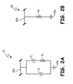
- FIG. 2A is a circuit diagram illustrating an impedance circuit according to an embodiment of the present invention.
- FIG. 2B is a circuit diagram illustrating an impedance circuit according to another embodiment of the present invention.
- the present invention describes a system and method for connecting a midpoint of a dual-DC bus of an active rectifier system to system ground.
- Active rectifiers such as Vienna rectifiers for three-phase power systems, may provide DC output power on a dual-DC bus. These dual-DC buses have midpoints which are different than the power system ground. It is desirable to connect the midpoint of a dual-DC bus to the power system ground.
- directly tying the midpoint to the power system ground can create issues. For instance, when the active rectifier controller is turned off, there could be a third harmonic current flowing in the short-circuit path to ground. This third harmonic current can be quite high, despite the active rectifier being inactive. Even if the active rectifier is activated prior to applying AC power, there is a transient period before the active rectifier reaches a steady-state in which a third harmonic current may be very high.
- the system includes an AC power source, an EMI filter, an active rectifier, and a dual-DC bus that provides DC power to a load from the active rectifier.
- the dual-DC bus includes a positive voltage line, a negative voltage line, and a midpoint line.
- the AC power source is connected to the system ground.
- One embodiment of the present invention involves connecting the midpoint of the dual-DC bus to the system ground through a high frequency impedance circuit.
- This high frequency impedance circuit comprises a capacitor in parallel with a resistor-capacitor (RC) circuit.
- the midpoint of the dual-DC bus is connected to the system ground through a power resistor which is used to reduce the amplitude of a third-harmonic common-mode current to an acceptable level.
- FIG. 1 is a circuit diagram illustrating system 10 for connecting the midpoint of a dual-DC bus to power system ground according to an embodiment of the present invention.
- System 10 includes power source 12 , EMI filter 14 , active rectifier 16 , load 18 , dual-DC bus lines 20 a - 20 c, impedance circuit 22 , and system grounds 24 a and 24 b.
- power source 12 is a three-phase AC power source connected to EMI filter 14 . In other embodiments, power source 12 may include any number of phases.
- Power source 12 is connected to system ground 24 a.
- active rectifier 16 may be implemented as any known active rectifier circuit.
- EMI filter 14 is utilized to filter EMI generated within system 10 .
- EMI filter 14 may include, among other things, common-mode filters and differential-mode filters.
- Load 18 is any load that requires DC power such as, for example, an electric motor drive.
- Active rectifier 16 is used to convert the three-phase AC power provided by power source 12 into DC power provided on dual-DC bus lines 20 a - 20 c.
- Active rectifier 16 includes an LCL filter consisting of inductors L F1 and L F2 , corresponding resistances R LF1 and R LF2 , capacitors C F , and corresponding resistances R CF . This LCL filter is implemented to further filter EMI within system 10 .
- Active rectifier 16 also includes switches S 1 -S 6 , diodes D 1 -D 12 , body diodes D B1 -D B6 , and output capacitors C OUT1 and C OUT2 . Switches S 1 -S 6 are controlled by switching controller 26 .
- Switching controller 26 is implemented using any suitable controller such as, for example, a microcontroller.
- Switching controller 26 utilizes, for example, pulse-width modulation (PWM) to control switches S 1 -S 6 in order to control the output voltage on the dual-DC bus.
- PWM pulse-width modulation
- Active rectifier 16 allows bidirectional flow between the input and output of the rectifier. Although illustrated as a single rectifier, active rectifier 16 may comprise multiple active rectifiers in parallel to provide better performance.
- Load 18 is provided DC power on a dual-DC bus comprising lines 20 a - 20 c from active rectifier 16 .
- Output 20 a provides positive DC voltage from active rectifier 16 ;
- output 20 c provides negative DC voltage from active rectifier 16 ;
- output 20 b is a neutral output from active rectifier 16 .
- This type of dual-DC bus configuration provides better efficiency for loads such as, for example, motor drives.
- Impedance circuit 22 is used to connect midpoint 20 b to system ground 24 b.
- System ground 24 b is the same as system ground 24 a. Because of this, a third harmonic common-mode current may flow in the short-circuit path created by connecting midpoint 20 b to system ground 24 b.
- Impedance circuit 22 is utilized to handle this third harmonic common-mode current and allow midpoint 20 b to be connected to system ground 24 b.
- FIG. 2A is a circuit diagram illustrating impedance circuit 22 according to an embodiment of the present invention.
- Midpoint line 20 b is connected through a high-frequency impedance circuit to system ground 24 b, which is the same ground as system ground 24 a ( FIG. 1 ). This is done to provide an impedance for any high-frequency third harmonic current flowing in the short circuit path created by connecting midpoint line 20 b to system ground 24 b.
- Impedance circuit 22 includes capacitors C 1 and C 2 , and resistor R 1 . Capacitor C 1 and resistor R 1 form an RC circuit that is connected in parallel with capacitor C 2 .
- Impedance circuit 20 provides a high-frequency impedance path for common-mode EMI on the load side of active rectifier 16 .
- impedance circuit 22 may be implemented using any circuit that creates a high frequency impedance between midpoint 20 b and system ground 24 b.
- FIG. 2B is a circuit diagram illustrating impedance circuit 22 according to another embodiment of the present invention.
- Power resistor 30 is implemented between midpoint line 20 b and system ground 24 b. This provides damping for the third harmonic common-mode current flowing in the short-circuit path created by connecting midpoint 20 b to system ground 24 b.
- the value of resistance for power resistor 30 is any value sufficient to damp the third harmonic current, such as, for example, between 200 ⁇ and 1 K ⁇ . This resistor should have a power rating sufficient to handle this third harmonic current such as, for example, between 10 watts and 20 watts.
- a system includes: a power source that provides alternating current (AC) power and is connected to system ground, a dual-DC bus that provides direct current (DC) power to a load, and comprises a positive line, a negative line, and a midpoint line, an active rectifier that converts AC power from the power source to DC power for the dual-DC bus, and an impedance circuit connected between the midpoint of the dual-DC bus and the system ground that provides impedance for third harmonic common-mode current.
- AC alternating current
- DC direct current
- the system of the preceding paragraph can optionally include, additionally and/or alternatively, any one or more of the following features, configurations and/or additional components.
- the impedance circuit can comprise a first capacitor, and a resistor-capacitor (RC) circuit comprising a resistor connected in series with a second capacitor, wherein the RC circuit is connected in parallel with the first capacitor.
- RC resistor-capacitor
- the impedance circuit can comprise a power resistor.
- the power resistor has a resistance of between 200 ⁇ and 1 K ⁇ .
- the power resistor has a power rating of between 10 watts and 20 watts.
- the power source is three-phase power source.
- the active rectifier is controlled by a controller.
- An electromagnetic interference (EMI) filter that filters EMI generated by the active rectifier.
- a method includes: providing alternating current (AC) power to an active rectifier from an AC power source that is grounded to system ground, converting the AC power into direct current (DC) power using an active rectifier, providing the DC power from the active rectifier to a dual-DC bus that includes a positive line, a negative line, and a midpoint line, connecting the midpoint line to the system ground through an impedance circuit, and providing impedance for third-harmonic common-mode current using the impedance circuit.
- AC alternating current
- DC direct current
- the method of the preceding paragraph can optionally include, additionally and/or alternatively, any one or more of the following features, configurations and/or additional components.
- the impedance circuit can comprise a first capacitor, and a resistor-capacitor (RC) circuit comprising a resistor connected in series with a second capacitor, wherein the RC circuit is connected in parallel with the first capacitor.
- RC resistor-capacitor
- the impedance circuit can comprise a power resistor.
- the power resistor has a resistance of between 200 ⁇ and 1 K ⁇ .
- the power resistor has a power rating of between 10 watts and 20 watts.
- the power source is three-phase power source.
- the active rectifier is controlled by a controller.
- the method further includes filtering EMI generated by the active rectifier using an EMI filter.
Landscapes
- Engineering & Computer Science (AREA)
- Power Engineering (AREA)
- Rectifiers (AREA)
- Power Conversion In General (AREA)
- Direct Current Feeding And Distribution (AREA)
Abstract
Description
Claims (8)
Priority Applications (2)
| Application Number | Priority Date | Filing Date | Title |
|---|---|---|---|
| US13/649,963 US9099926B2 (en) | 2012-10-11 | 2012-10-11 | System and method for connecting the midpoint of a dual-DC bus to ground |
| EP13187390.3A EP2720367B1 (en) | 2012-10-11 | 2013-10-04 | System and method for connecting the midpoint of a dual-DC bus to ground |
Applications Claiming Priority (1)
| Application Number | Priority Date | Filing Date | Title |
|---|---|---|---|
| US13/649,963 US9099926B2 (en) | 2012-10-11 | 2012-10-11 | System and method for connecting the midpoint of a dual-DC bus to ground |
Publications (2)
| Publication Number | Publication Date |
|---|---|
| US20140104900A1 US20140104900A1 (en) | 2014-04-17 |
| US9099926B2 true US9099926B2 (en) | 2015-08-04 |
Family
ID=49274575
Family Applications (1)
| Application Number | Title | Priority Date | Filing Date |
|---|---|---|---|
| US13/649,963 Active 2032-12-06 US9099926B2 (en) | 2012-10-11 | 2012-10-11 | System and method for connecting the midpoint of a dual-DC bus to ground |
Country Status (2)
| Country | Link |
|---|---|
| US (1) | US9099926B2 (en) |
| EP (1) | EP2720367B1 (en) |
Cited By (3)
| Publication number | Priority date | Publication date | Assignee | Title |
|---|---|---|---|---|
| US20140268933A1 (en) * | 2013-03-18 | 2014-09-18 | Delta Electronics, Inc. | Filter device, power converter and common mode noise suppression method |
| US20150009727A1 (en) * | 2013-07-02 | 2015-01-08 | Delta Electronics (Shanghai) Co., Ltd. | Power converter with low common mode noise |
| WO2018122835A1 (en) | 2016-12-29 | 2018-07-05 | A.B. Power Ltd. | Regulated power supply |
Families Citing this family (4)
| Publication number | Priority date | Publication date | Assignee | Title |
|---|---|---|---|---|
| US20140103650A1 (en) * | 2012-10-11 | 2014-04-17 | Hamilton Sundstrand Corporation | Dual-dc bus starter/generator |
| US9318253B2 (en) | 2014-05-02 | 2016-04-19 | Hamilton Sundstrand Corporation | Hybrid planar common-mode choke |
| CN109936298B (en) * | 2017-12-15 | 2021-02-19 | 日立江森自控空调有限公司 | Rectifier circuit and power supply device |
| EP3930159B1 (en) * | 2020-06-26 | 2023-05-17 | Siemens Aktiengesellschaft | Active rectifier circuit |
Citations (9)
| Publication number | Priority date | Publication date | Assignee | Title |
|---|---|---|---|---|
| US20020076067A1 (en) * | 2000-12-15 | 2002-06-20 | Rocky Caldwell | Dynamic allocation of power supplied by a power supply and frequency agile spectral filtering of signals |
| US20030222609A1 (en) * | 2002-05-29 | 2003-12-04 | Bristol Compressors | System and method for soft starting a three phase motor |
| US20050041442A1 (en) * | 2002-11-18 | 2005-02-24 | Balu Balakrishnan | Method and apparatus for providing input EMI filtering in power supplies |
| US20080013352A1 (en) * | 2006-07-13 | 2008-01-17 | Baker Donal E | Active rectifier system with power factor correction |
| US7633772B2 (en) * | 2004-09-20 | 2009-12-15 | Ullrich Joseph Arnold | AC power distribution system with transient suppression and harmonic attenuation |
| US20100045247A1 (en) * | 2005-04-20 | 2010-02-25 | Nxp B.V. | Parallel arranged linear amplifier and dc-dc converter |
| US20110031818A1 (en) * | 2006-09-26 | 2011-02-10 | Tai-Her Yang | Circuit installation capable of full voltage activation, division voltage operation and delayed breaking |
| US8472215B2 (en) * | 2010-01-13 | 2013-06-25 | Kabushiki Kaisha Toshiba | Grid-tie inverter for interconnecting AC voltage to electric power grid |
| US20130163292A1 (en) * | 2011-12-22 | 2013-06-27 | General Electric Company | Mid-point voltage control |
Family Cites Families (4)
| Publication number | Priority date | Publication date | Assignee | Title |
|---|---|---|---|---|
| US8115444B2 (en) * | 2006-05-31 | 2012-02-14 | Honeywell International, Inc. | Common mode filter for motor controllers |
| CN102474218B (en) * | 2009-07-01 | 2014-09-17 | 株式会社安川电机 | Motor driving device |
| KR101543039B1 (en) * | 2009-10-26 | 2015-08-10 | 현대자동차주식회사 | Method of Circuit Configuration of Inverter Capacitor Module Using Impedance Matching Method |
| DE102011013247A1 (en) * | 2010-09-09 | 2012-03-15 | Esw Gmbh | Device for suppressing asymmetric electromagnetic interference on asymmetric electric high power line e.g. direct current line, has compensation circuit generating compensation signal and comprising passive filter component |
-
2012
- 2012-10-11 US US13/649,963 patent/US9099926B2/en active Active
-
2013
- 2013-10-04 EP EP13187390.3A patent/EP2720367B1/en active Active
Patent Citations (9)
| Publication number | Priority date | Publication date | Assignee | Title |
|---|---|---|---|---|
| US20020076067A1 (en) * | 2000-12-15 | 2002-06-20 | Rocky Caldwell | Dynamic allocation of power supplied by a power supply and frequency agile spectral filtering of signals |
| US20030222609A1 (en) * | 2002-05-29 | 2003-12-04 | Bristol Compressors | System and method for soft starting a three phase motor |
| US20050041442A1 (en) * | 2002-11-18 | 2005-02-24 | Balu Balakrishnan | Method and apparatus for providing input EMI filtering in power supplies |
| US7633772B2 (en) * | 2004-09-20 | 2009-12-15 | Ullrich Joseph Arnold | AC power distribution system with transient suppression and harmonic attenuation |
| US20100045247A1 (en) * | 2005-04-20 | 2010-02-25 | Nxp B.V. | Parallel arranged linear amplifier and dc-dc converter |
| US20080013352A1 (en) * | 2006-07-13 | 2008-01-17 | Baker Donal E | Active rectifier system with power factor correction |
| US20110031818A1 (en) * | 2006-09-26 | 2011-02-10 | Tai-Her Yang | Circuit installation capable of full voltage activation, division voltage operation and delayed breaking |
| US8472215B2 (en) * | 2010-01-13 | 2013-06-25 | Kabushiki Kaisha Toshiba | Grid-tie inverter for interconnecting AC voltage to electric power grid |
| US20130163292A1 (en) * | 2011-12-22 | 2013-06-27 | General Electric Company | Mid-point voltage control |
Cited By (5)
| Publication number | Priority date | Publication date | Assignee | Title |
|---|---|---|---|---|
| US20140268933A1 (en) * | 2013-03-18 | 2014-09-18 | Delta Electronics, Inc. | Filter device, power converter and common mode noise suppression method |
| US9455646B2 (en) * | 2013-03-18 | 2016-09-27 | Delta Electronics, Inc. | Filter device, power converter and common mode noise suppression method |
| US20150009727A1 (en) * | 2013-07-02 | 2015-01-08 | Delta Electronics (Shanghai) Co., Ltd. | Power converter with low common mode noise |
| US9312753B2 (en) * | 2013-07-02 | 2016-04-12 | Delta Electronics (Shanghai) Co., Ltd. | Power converter with low common mode noise |
| WO2018122835A1 (en) | 2016-12-29 | 2018-07-05 | A.B. Power Ltd. | Regulated power supply |
Also Published As
| Publication number | Publication date |
|---|---|
| EP2720367A3 (en) | 2017-05-31 |
| US20140104900A1 (en) | 2014-04-17 |
| EP2720367A2 (en) | 2014-04-16 |
| EP2720367B1 (en) | 2020-09-02 |
Similar Documents
| Publication | Publication Date | Title |
|---|---|---|
| US9099926B2 (en) | System and method for connecting the midpoint of a dual-DC bus to ground | |
| US9166472B2 (en) | EMI filtering for active rectifier power systems | |
| AU2005281207B2 (en) | Polyphase current supplying circuit and driver apparatus | |
| CA2580104C (en) | Improved power converter with reduced common mode voltage | |
| US7602622B2 (en) | Compensator with filter for use with a three-phase drive powering a one-phase load | |
| US9401658B2 (en) | Power supply apparatus and method of generating power by the same | |
| KR102111144B1 (en) | Passive power factor correction incorporating ac/dc conversion | |
| CN205657581U (en) | Converter device of multistage converter with parallel connection | |
| US9584039B2 (en) | Regulated AC-DC hybrid rectifier | |
| CN102027677A (en) | Lossy triphase low-pass filter | |
| WO2013083761A2 (en) | Asynchronous motor unit comprising a frequency converter with electrical isolation in the dc voltage intermediate circuit | |
| US9438132B2 (en) | Multilevel AC/DC power converting method and converter device thereof | |
| Ghosh et al. | Novel active ripple filtering schemes used in little box inverter | |
| EP3394971B1 (en) | Grounding scheme for power conversion system | |
| Arifin et al. | Input switched closed-loop single phase ĈUK AC to DC converter with improved power quality | |
| Junaid et al. | Analysis and design of buck-boost converter for power quality improvement in high frequency on/off-line UPS system | |
| US11569792B2 (en) | Integrated inverter output passive filters for eliminating both common mode and differential mode harmonics in pulse-width modulation motor drives and methods of manufacture and use thereof | |
| Ounejjar et al. | Fourteen-band hysteresis controller of the fifteen-level packed U cells converter | |
| Ounejjar et al. | Multilevel hysteresis controller of the novel seven-level packed U cells converter | |
| Sanjay et al. | Adaptable speed bridgeless SEPIC converter VSI fed BLDC motor drive | |
| CN204807678U (en) | Motor type test system | |
| Abedin et al. | A single phase buck-boost ac-ac converter with low input current thd and high input power factor | |
| Shin et al. | CLC filter design of a flyback-inverter for photovoltaic systems | |
| US11863085B2 (en) | Converter assembly | |
| Kabir et al. | Ćuk topology based single switch single phase high power quality AC voltage controller |
Legal Events
| Date | Code | Title | Description |
|---|---|---|---|
| AS | Assignment |
Owner name: HAMILTON SUNDSTRAND CORPORATION, CONNECTICUT Free format text: ASSIGNMENT OF ASSIGNORS INTEREST;ASSIGNOR:NGUYEN, VIETSON M.;REEL/FRAME:029115/0495 Effective date: 20121009 |
|
| STCF | Information on status: patent grant |
Free format text: PATENTED CASE |
|
| MAFP | Maintenance fee payment |
Free format text: PAYMENT OF MAINTENANCE FEE, 4TH YEAR, LARGE ENTITY (ORIGINAL EVENT CODE: M1551); ENTITY STATUS OF PATENT OWNER: LARGE ENTITY Year of fee payment: 4 |
|
| MAFP | Maintenance fee payment |
Free format text: PAYMENT OF MAINTENANCE FEE, 8TH YEAR, LARGE ENTITY (ORIGINAL EVENT CODE: M1552); ENTITY STATUS OF PATENT OWNER: LARGE ENTITY Year of fee payment: 8 |