US9081001B2 - Diagnostic systems and instruments - Google Patents
Diagnostic systems and instruments Download PDFInfo
- Publication number
- US9081001B2 US9081001B2 US13/844,450 US201313844450A US9081001B2 US 9081001 B2 US9081001 B2 US 9081001B2 US 201313844450 A US201313844450 A US 201313844450A US 9081001 B2 US9081001 B2 US 9081001B2
- Authority
- US
- United States
- Prior art keywords
- cartridge
- pump
- diagnostic
- diagnostic system
- reservoir
- Prior art date
- Legal status (The legal status is an assumption and is not a legal conclusion. Google has not performed a legal analysis and makes no representation as to the accuracy of the status listed.)
- Expired - Fee Related, expires
Links
Images


Classifications
-
- B—PERFORMING OPERATIONS; TRANSPORTING
- B01—PHYSICAL OR CHEMICAL PROCESSES OR APPARATUS IN GENERAL
- B01L—CHEMICAL OR PHYSICAL LABORATORY APPARATUS FOR GENERAL USE
- B01L3/00—Containers or dishes for laboratory use, e.g. laboratory glassware; Droppers
- B01L3/52—Containers specially adapted for storing or dispensing a reagent
- B01L3/527—Containers specially adapted for storing or dispensing a reagent for a plurality of reagents
-
- G—PHYSICS
- G01—MEASURING; TESTING
- G01N—INVESTIGATING OR ANALYSING MATERIALS BY DETERMINING THEIR CHEMICAL OR PHYSICAL PROPERTIES
- G01N33/00—Investigating or analysing materials by specific methods not covered by groups G01N1/00 - G01N31/00
- G01N33/48—Biological material, e.g. blood, urine; Haemocytometers
- G01N33/50—Chemical analysis of biological material, e.g. blood, urine; Testing involving biospecific ligand binding methods; Immunological testing
-
- B—PERFORMING OPERATIONS; TRANSPORTING
- B65—CONVEYING; PACKING; STORING; HANDLING THIN OR FILAMENTARY MATERIAL
- B65B—MACHINES, APPARATUS OR DEVICES FOR, OR METHODS OF, PACKAGING ARTICLES OR MATERIALS; UNPACKING
- B65B1/00—Packaging fluent solid material, e.g. powders, granular or loose fibrous material, loose masses of small articles, in individual containers or receptacles, e.g. bags, sacks, boxes, cartons, cans, or jars
- B65B1/04—Methods of, or means for, filling the material into the containers or receptacles
-
- B—PERFORMING OPERATIONS; TRANSPORTING
- B65—CONVEYING; PACKING; STORING; HANDLING THIN OR FILAMENTARY MATERIAL
- B65B—MACHINES, APPARATUS OR DEVICES FOR, OR METHODS OF, PACKAGING ARTICLES OR MATERIALS; UNPACKING
- B65B3/00—Packaging plastic material, semiliquids, liquids or mixed solids and liquids, in individual containers or receptacles, e.g. bags, sacks, boxes, cartons, cans, or jars
- B65B3/04—Methods of, or means for, filling the material into the containers or receptacles
-
- B—PERFORMING OPERATIONS; TRANSPORTING
- B65—CONVEYING; PACKING; STORING; HANDLING THIN OR FILAMENTARY MATERIAL
- B65B—MACHINES, APPARATUS OR DEVICES FOR, OR METHODS OF, PACKAGING ARTICLES OR MATERIALS; UNPACKING
- B65B5/00—Packaging individual articles in containers or receptacles, e.g. bags, sacks, boxes, cartons, cans, jars
- B65B5/04—Packaging single articles
-
- B—PERFORMING OPERATIONS; TRANSPORTING
- B65—CONVEYING; PACKING; STORING; HANDLING THIN OR FILAMENTARY MATERIAL
- B65B—MACHINES, APPARATUS OR DEVICES FOR, OR METHODS OF, PACKAGING ARTICLES OR MATERIALS; UNPACKING
- B65B55/00—Preserving, protecting or purifying packages or package contents in association with packaging
-
- F—MECHANICAL ENGINEERING; LIGHTING; HEATING; WEAPONS; BLASTING
- F04—POSITIVE - DISPLACEMENT MACHINES FOR LIQUIDS; PUMPS FOR LIQUIDS OR ELASTIC FLUIDS
- F04B—POSITIVE-DISPLACEMENT MACHINES FOR LIQUIDS; PUMPS
- F04B49/00—Control, e.g. of pump delivery, or pump pressure of, or safety measures for, machines, pumps, or pumping installations, not otherwise provided for, or of interest apart from, groups F04B1/00 - F04B47/00
- F04B49/06—Control using electricity
- F04B49/065—Control using electricity and making use of computers
-
- F—MECHANICAL ENGINEERING; LIGHTING; HEATING; WEAPONS; BLASTING
- F04—POSITIVE - DISPLACEMENT MACHINES FOR LIQUIDS; PUMPS FOR LIQUIDS OR ELASTIC FLUIDS
- F04B—POSITIVE-DISPLACEMENT MACHINES FOR LIQUIDS; PUMPS
- F04B49/00—Control, e.g. of pump delivery, or pump pressure of, or safety measures for, machines, pumps, or pumping installations, not otherwise provided for, or of interest apart from, groups F04B1/00 - F04B47/00
- F04B49/10—Other safety measures
- F04B49/106—Responsive to pumped volume
-
- G—PHYSICS
- G01—MEASURING; TESTING
- G01N—INVESTIGATING OR ANALYSING MATERIALS BY DETERMINING THEIR CHEMICAL OR PHYSICAL PROPERTIES
- G01N21/00—Investigating or analysing materials by the use of optical means, i.e. using sub-millimetre waves, infrared, visible or ultraviolet light
- G01N21/62—Systems in which the material investigated is excited whereby it emits light or causes a change in wavelength of the incident light
- G01N21/66—Systems in which the material investigated is excited whereby it emits light or causes a change in wavelength of the incident light electrically excited, e.g. electroluminescence
-
- G—PHYSICS
- G01—MEASURING; TESTING
- G01N—INVESTIGATING OR ANALYSING MATERIALS BY DETERMINING THEIR CHEMICAL OR PHYSICAL PROPERTIES
- G01N21/00—Investigating or analysing materials by the use of optical means, i.e. using sub-millimetre waves, infrared, visible or ultraviolet light
- G01N21/75—Systems in which material is subjected to a chemical reaction, the progress or the result of the reaction being investigated
- G01N21/76—Chemiluminescence; Bioluminescence
-
- G—PHYSICS
- G01—MEASURING; TESTING
- G01N—INVESTIGATING OR ANALYSING MATERIALS BY DETERMINING THEIR CHEMICAL OR PHYSICAL PROPERTIES
- G01N27/00—Investigating or analysing materials by the use of electric, electrochemical, or magnetic means
- G01N27/26—Investigating or analysing materials by the use of electric, electrochemical, or magnetic means by investigating electrochemical variables; by using electrolysis or electrophoresis
- G01N27/28—Electrolytic cell components
- G01N27/30—Electrodes, e.g. test electrodes; Half-cells
- G01N27/327—Biochemical electrodes, e.g. electrical or mechanical details for in vitro measurements
- G01N27/3271—Amperometric enzyme electrodes for analytes in body fluids, e.g. glucose in blood
- G01N27/3273—Devices therefor, e.g. test element readers, circuitry
-
- G—PHYSICS
- G01—MEASURING; TESTING
- G01N—INVESTIGATING OR ANALYSING MATERIALS BY DETERMINING THEIR CHEMICAL OR PHYSICAL PROPERTIES
- G01N33/00—Investigating or analysing materials by specific methods not covered by groups G01N1/00 - G01N31/00
- G01N33/48—Biological material, e.g. blood, urine; Haemocytometers
- G01N33/50—Chemical analysis of biological material, e.g. blood, urine; Testing involving biospecific ligand binding methods; Immunological testing
- G01N33/53—Immunoassay; Biospecific binding assay; Materials therefor
- G01N33/536—Immunoassay; Biospecific binding assay; Materials therefor with immune complex formed in liquid phase
-
- G—PHYSICS
- G01—MEASURING; TESTING
- G01N—INVESTIGATING OR ANALYSING MATERIALS BY DETERMINING THEIR CHEMICAL OR PHYSICAL PROPERTIES
- G01N33/00—Investigating or analysing materials by specific methods not covered by groups G01N1/00 - G01N31/00
- G01N33/48—Biological material, e.g. blood, urine; Haemocytometers
- G01N33/50—Chemical analysis of biological material, e.g. blood, urine; Testing involving biospecific ligand binding methods; Immunological testing
- G01N33/53—Immunoassay; Biospecific binding assay; Materials therefor
- G01N33/543—Immunoassay; Biospecific binding assay; Materials therefor with an insoluble carrier for immobilising immunochemicals
-
- G—PHYSICS
- G01—MEASURING; TESTING
- G01N—INVESTIGATING OR ANALYSING MATERIALS BY DETERMINING THEIR CHEMICAL OR PHYSICAL PROPERTIES
- G01N33/00—Investigating or analysing materials by specific methods not covered by groups G01N1/00 - G01N31/00
- G01N33/48—Biological material, e.g. blood, urine; Haemocytometers
- G01N33/50—Chemical analysis of biological material, e.g. blood, urine; Testing involving biospecific ligand binding methods; Immunological testing
- G01N33/58—Chemical analysis of biological material, e.g. blood, urine; Testing involving biospecific ligand binding methods; Immunological testing involving labelled substances
- G01N33/582—Chemical analysis of biological material, e.g. blood, urine; Testing involving biospecific ligand binding methods; Immunological testing involving labelled substances with fluorescent label
-
- G—PHYSICS
- G01—MEASURING; TESTING
- G01N—INVESTIGATING OR ANALYSING MATERIALS BY DETERMINING THEIR CHEMICAL OR PHYSICAL PROPERTIES
- G01N35/00—Automatic analysis not limited to methods or materials provided for in any single one of groups G01N1/00 - G01N33/00; Handling materials therefor
- G01N35/00584—Control arrangements for automatic analysers
- G01N35/00722—Communications; Identification
-
- G—PHYSICS
- G01—MEASURING; TESTING
- G01N—INVESTIGATING OR ANALYSING MATERIALS BY DETERMINING THEIR CHEMICAL OR PHYSICAL PROPERTIES
- G01N35/00—Automatic analysis not limited to methods or materials provided for in any single one of groups G01N1/00 - G01N33/00; Handling materials therefor
- G01N35/0098—Automatic analysis not limited to methods or materials provided for in any single one of groups G01N1/00 - G01N33/00; Handling materials therefor involving analyte bound to insoluble magnetic carrier, e.g. using magnetic separation
-
- H—ELECTRICITY
- H05—ELECTRIC TECHNIQUES NOT OTHERWISE PROVIDED FOR
- H05B—ELECTRIC HEATING; ELECTRIC LIGHT SOURCES NOT OTHERWISE PROVIDED FOR; CIRCUIT ARRANGEMENTS FOR ELECTRIC LIGHT SOURCES, IN GENERAL
- H05B1/00—Details of electric heating devices
- H05B1/02—Automatic switching arrangements specially adapted to apparatus ; Control of heating devices
- H05B1/0227—Applications
- H05B1/023—Industrial applications
- H05B1/025—For medical applications
-
- B—PERFORMING OPERATIONS; TRANSPORTING
- B01—PHYSICAL OR CHEMICAL PROCESSES OR APPARATUS IN GENERAL
- B01L—CHEMICAL OR PHYSICAL LABORATORY APPARATUS FOR GENERAL USE
- B01L2200/00—Solutions for specific problems relating to chemical or physical laboratory apparatus
- B01L2200/10—Integrating sample preparation and analysis in single entity, e.g. lab-on-a-chip concept
-
- B—PERFORMING OPERATIONS; TRANSPORTING
- B01—PHYSICAL OR CHEMICAL PROCESSES OR APPARATUS IN GENERAL
- B01L—CHEMICAL OR PHYSICAL LABORATORY APPARATUS FOR GENERAL USE
- B01L2200/00—Solutions for specific problems relating to chemical or physical laboratory apparatus
- B01L2200/16—Reagents, handling or storing thereof
-
- B—PERFORMING OPERATIONS; TRANSPORTING
- B01—PHYSICAL OR CHEMICAL PROCESSES OR APPARATUS IN GENERAL
- B01L—CHEMICAL OR PHYSICAL LABORATORY APPARATUS FOR GENERAL USE
- B01L2300/00—Additional constructional details
- B01L2300/04—Closures and closing means
- B01L2300/041—Connecting closures to device or container
- B01L2300/042—Caps; Plugs
-
- B—PERFORMING OPERATIONS; TRANSPORTING
- B01—PHYSICAL OR CHEMICAL PROCESSES OR APPARATUS IN GENERAL
- B01L—CHEMICAL OR PHYSICAL LABORATORY APPARATUS FOR GENERAL USE
- B01L2300/00—Additional constructional details
- B01L2300/08—Geometry, shape and general structure
- B01L2300/0861—Configuration of multiple channels and/or chambers in a single devices
-
- B—PERFORMING OPERATIONS; TRANSPORTING
- B01—PHYSICAL OR CHEMICAL PROCESSES OR APPARATUS IN GENERAL
- B01L—CHEMICAL OR PHYSICAL LABORATORY APPARATUS FOR GENERAL USE
- B01L2300/00—Additional constructional details
- B01L2300/10—Means to control humidity and/or other gases
- B01L2300/105—Means to control humidity and/or other gases using desiccants
-
- G—PHYSICS
- G01—MEASURING; TESTING
- G01N—INVESTIGATING OR ANALYSING MATERIALS BY DETERMINING THEIR CHEMICAL OR PHYSICAL PROPERTIES
- G01N35/00—Automatic analysis not limited to methods or materials provided for in any single one of groups G01N1/00 - G01N33/00; Handling materials therefor
- G01N35/10—Devices for transferring samples or any liquids to, in, or from, the analysis apparatus, e.g. suction devices, injection devices
- G01N35/1079—Devices for transferring samples or any liquids to, in, or from, the analysis apparatus, e.g. suction devices, injection devices with means for piercing stoppers or septums
-
- Y—GENERAL TAGGING OF NEW TECHNOLOGICAL DEVELOPMENTS; GENERAL TAGGING OF CROSS-SECTIONAL TECHNOLOGIES SPANNING OVER SEVERAL SECTIONS OF THE IPC; TECHNICAL SUBJECTS COVERED BY FORMER USPC CROSS-REFERENCE ART COLLECTIONS [XRACs] AND DIGESTS
- Y10—TECHNICAL SUBJECTS COVERED BY FORMER USPC
- Y10T—TECHNICAL SUBJECTS COVERED BY FORMER US CLASSIFICATION
- Y10T436/00—Chemistry: analytical and immunological testing
- Y10T436/25—Chemistry: analytical and immunological testing including sample preparation
- Y10T436/2575—Volumetric liquid transfer
Definitions
- the present disclosure relates to a clinical diagnostic system.
- a clinical diagnostic instrument with a disposable cartridge useful for diagnostic tests in a clinical setting is disclosed.
- Clinical laboratory testing requires instruments and tests with high accuracy and precision. Containing costs for lab tests is also important. Some clinical lab tests are conducted in high volume because of the large number of patients undergoing tests. There are drawbacks associated with present procedures that require sequential and additional steps and transfers of multiple reagents to produce the assay. Each additional step for a detection assay increases the degree of difficulty for execution and may even increase chances of contamination or error by the operator and is prone to misuse, thereby, resulting in a higher margin for error. Thus, it is desirable to have a clinical diagnostic instrument that can reduce the undesirable processing steps of transferring samples to labs and instead complete a diagnostic test in a physician's office or at a patient's bedside. Such an instrument would inevitably reduce processing costs and cut down on opportunity for error and contamination.
- the disclosure relates generally to a clinical diagnostic system.
- a clinical diagnostic instrument with a disposable cartridge useful for diagnostic tests in a clinical setting is disclosed.
- the disclosure relates generally to a diagnostic system having a closed fluidic pathway comprising a diagnostic instrument comprising at least two probes; a fluidic pathway; a non-electrochemiluminescence (ECL) detection system; an ECL detection system; and a pump; and a cartridge comprising at least one needle, at least one reservoir; at least one fluidic seal; and at least one fluidic channel; and a blood collection tube, the closed fluidic pathway, wherein the pathway begins and ends in the cartridge and has a substantially single direction of flow in a pathway fluidically connecting the diagnostic instrument and the cartridge.
- ECL non-electrochemiluminescence
- the disclosure relates generally to a diagnostic system having a closed fluidic pathway, wherein the at least one probe comprises a first probe and a waste probe, and wherein the closed fluidic pathway includes a first probe engagement with the cartridge and a waste probe engagement with the cartridge.
- the disclosure relates generally to a diagnostic system having a closed fluidic pathway, wherein the at least one reservoir comprises a first reservoir and a waste reservoir.
- the disclosure relates generally to a diagnostic system having a closed fluidic pathway, wherein the first reservoir and the waste reservoir are the same reservoir.
- the disclosure relates generally to a diagnostic system having a closed fluidic pathway, wherein the first reservoir and the waste reservoir are not the same reservoir.
- the disclosure relates generally to a diagnostic system having a closed fluidic pathway, wherein after the first reservoir is emptied, the first reservoir is used as the waste reservoir.
- the disclosure relates generally to a diagnostic system having a closed fluidic pathway, wherein after the first reservoir is emptied it becomes the waste reservoir.
- the disclosure relates generally to a diagnostic system having a closed fluidic pathway, wherein the first probe fluidically connects to a first reservoir of the disposable cartridge.
- the disclosure relates generally to a diagnostic system having a closed fluidic pathway, wherein the first reservoir contains diagnostic reagents.
- the disclosure relates generally to a diagnostic system having a closed fluidic pathway, wherein the waste probe fluidically connects to a waste reservoir of the disposable cartridge.
- the disclosure relates generally to a diagnostic system having a closed fluidic pathway, wherein the waste reservoir receives waste materials.
- the disclosure relates generally to a diagnostic system having a closed fluidic pathway, wherein waste materials include at least one of a processed reagent, a blood filtrate, and a processed plasma.
- the disclosure relates generally to a diagnostic system having a closed fluidic pathway, wherein the fluidic pathway has a diameter that is the same as a diameter of the at least one probe.
- the disclosure relates generally to a diagnostic system having a closed fluidic pathway, wherein the substantially single direction of flow reduces the potential for carryover between diagnostic tests such that there is substantially no detectable carryover between diagnostic tests.
- the disclosure relates generally to a diagnostic system having a closed fluidic pathway, wherein the substantially single direction of flow prevents carryover between different cartridges used with the diagnostic system such that there is substantially no detectable carryover between diagnostic tests.
- the disclosure relates generally to a diagnostic system having a closed fluidic pathway, wherein a fluid flows, in order, from a first reservoir to a first probe, to the non-ECL detection system, to the ECL detection system, through the pump, to a waste probe, and to a waste reservoir, each fluidically connected by the fluidic pathway.
- the disclosure relates generally to a diagnostic system having a closed fluidic pathway, wherein at least one reagent and at least one waste material are stored on the cartridge.
- the disclosure relates generally to a diagnostic system having a closed fluidic pathway, wherein at least one reagent and at least one waste material are stored on the cartridge and not in the diagnostic instrument.
- the disclosure relates generally to a diagnostic system having a closed fluidic pathway, further comprising a motion assembly.
- the disclosure relates generally to a diagnostic system having a closed fluidic pathway, wherein the motion assembly has two axes mechanically connected to the first probe and the waste probe.
- the disclosure relates generally to a diagnostic system having a closed fluidic pathway, wherein no sample is stored on the diagnostic instrument.
- the disclosure relates generally to a diagnostic system having a closed fluidic pathway, wherein no fluids are stored on the diagnostic instrument.
- the disclosure relates generally to a diagnostic system having a closed fluidic pathway, wherein no dry reagents are stored on the diagnostic instrument.
- the disclosure relates generally to a diagnostic system having a closed fluidic pathway, wherein all fluids are stored on the cartridge.
- the disclosure relates generally to a diagnostic system having a closed fluidic pathway, wherein all dry reagents are stored on the cartridge.
- the present disclosure relates generally to a diagnostic system having a closed fluidic pathway comprising a diagnostic instrument having a set of fluidic control elements comprising a non-electrochemiluminescence (ECL) detection system; a first probe fluidically connected to the non-ECL detection system by at least one fluidic tube; an ECL detection system fluidically connected to the non-ECL detection system by at least one fluidic tube; a pump fluidically connected to the ECL detection system by at least one fluidic tube and fluidically connected to a waste probe by at least one fluidic tube; and a motion assembly having two axes mechanically connected to the first and waste probes; and a cartridge having at least one needle, at least one reservoir; at least one fluidic seal; and at least one fluidic channel, wherein the closed fluidic pathway has a substantially single direction of flow in a pathway fluidically connecting the diagnostic instrument and the disposable cartridge.
- ECL non-electrochemiluminescence
- the present disclosure relates generally to a diagnostic system having a closed fluidic pathway, wherein the at least one reservoir comprises a first reservoir and a waste reservoir.
- the present disclosure relates generally to a diagnostic system having a closed fluidic pathway, wherein the first reservoir and the waste reservoir are the same reservoir.
- the present disclosure relates generally to a diagnostic system having a closed fluidic pathway, wherein the first reservoir and the waste reservoir are not the same reservoir.
- the present disclosure relates generally to a diagnostic system having a closed fluidic pathway, wherein after the first reservoir is emptied, the first reservoir is used as the waste reservoir.
- the present disclosure relates generally to a diagnostic system having a closed fluidic pathway, wherein after the first reservoir is emptied it becomes the waste reservoir.
- the present disclosure relates generally to a diagnostic system having a closed fluidic pathway, wherein the first probe fluidically connects to a first reservoir of the disposable cartridge.
- the present disclosure relates generally to a diagnostic system having a closed fluidic pathway, wherein the first reservoir contains diagnostic reagents.
- the present disclosure relates generally to a diagnostic system having a closed fluidic pathway, wherein the waste probe fluidically connects to a waste reservoir of the disposable cartridge.
- the present disclosure relates generally to a diagnostic system having a closed fluidic pathway, wherein the waste reservoir receives waste materials.
- the present disclosure relates generally to a diagnostic system having a closed fluidic pathway, wherein waste materials include at least one of a processed reagent, a blood filtrate, and a processed plasma.
- the present disclosure relates generally to a diagnostic system having a closed fluidic pathway, wherein the fluidic pathway has a diameter that is the same as a diameter of at least one probe.
- the present disclosure relates generally to a diagnostic system having a closed fluidic pathway, wherein the substantially single direction of flow reduces the potential for carryover between diagnostic tests such that there is substantially no detectable carryover between diagnostic tests.
- the present disclosure relates generally to a diagnostic system having a closed fluidic pathway, wherein the substantially single direction of flow prevents carryover between different cartridges used with the diagnostic system such that there is substantially no detectable carryover between diagnostic tests.
- the present disclosure relates generally to a diagnostic system having a closed fluidic pathway, wherein a fluid flows, in order, from a first reservoir to a first probe, to the non-ECL detection system, to the ECL detection system, through the pump, to a waste probe, and to a waste reservoir, each fluidically connected by the fluidic pathway.
- the present disclosure relates generally to a diagnostic system having a closed fluidic pathway, wherein at least one reagent and at least one waste material are stored on the cartridge and not in the diagnostic instrument.
- the present disclosure relates generally to a diagnostic system having a closed fluidic pathway, further comprising a motion assembly.
- the present disclosure relates generally to a diagnostic system having a closed fluidic pathway, wherein the motion assembly has two axes mechanically connected to the first probe and the waste probe.
- the present disclosure relates generally to a diagnostic system having a closed fluidic pathway, wherein no sample is stored on the diagnostic instrument.
- the present disclosure relates generally to a diagnostic system having a closed fluidic pathway, wherein no fluids are stored on the diagnostic instrument.
- the present disclosure relates generally to a diagnostic system having a closed fluidic pathway, wherein no dry reagents are stored on the diagnostic instrument.
- the present disclosure relates generally to a diagnostic system having a closed fluidic pathway, wherein all fluids are stored on the cartridge.
- the present disclosure relates generally to a diagnostic system having a closed fluidic pathway, wherein all dry reagents are stored on the cartridge.
- the present disclosure relates generally to a diagnostic system having a closed fluidic pathway comprising a diagnostic instrument having a set of fluidic control elements comprising a non-ECL detection system; a first probe fluidically connected to the non-ECL detection system by at least one fluidic tube; a pump fluidically connected to the ECL detection system by at least one fluidic tube and fluidically connected to a waste probe by at least one fluidic tube; and a cartridge having at least one needle, at least one reservoir; at least one fluidic seal; and at least one fluidic channel, wherein the closed fluidic pathway has a substantially single direction of flow in a pathway fluidically connecting the diagnostic instrument and the disposable cartridge.
- the present disclosure relates generally to a diagnostic system having a closed fluidic pathway, wherein the non-ECL detection system is fluidically connected to the first probe by at least one fluidic tube and fluidically connected to the ECL detection system by at least one fluidic tube.
- the present disclosure relates generally to a diagnostic system having a closed fluidic pathway, wherein the at least one reservoir comprises a first reservoir and a waste reservoir.
- the present disclosure relates generally to a diagnostic system having a closed fluidic pathway, wherein the first reservoir and the waste reservoir are the same reservoir.
- the present disclosure relates generally to a diagnostic system having a closed fluidic pathway, wherein the first reservoir and the waste reservoir are not the same reservoir.
- the present disclosure relates generally to a diagnostic system having a closed fluidic pathway, wherein the first probe fluidically connects to a first reservoir of the disposable cartridge.
- the present disclosure relates generally to a diagnostic system having a closed fluidic pathway, wherein the first reservoir contains diagnostic reagents.
- the present disclosure relates generally to a diagnostic system having a closed fluidic pathway, wherein the waste probe fluidically connects to a waste reservoir of the disposable cartridge.
- the present disclosure relates generally to a diagnostic system having a closed fluidic pathway, wherein the waste reservoir receives waste materials.
- the present disclosure relates generally to a diagnostic system having a closed fluidic pathway, wherein waste materials include at least one of a processed reagent, a blood filtrate, and a processed plasma.
- the present disclosure relates generally to a diagnostic system having a closed fluidic pathway, wherein the fluidic pathway has a diameter that is the same as a diameter of the at least one probe.
- the present disclosure relates generally to a diagnostic system having a closed fluidic pathway, wherein the substantially single direction of flow reduces the potential for carryover between diagnostic tests such that there is substantially no detectable carryover between diagnostic tests.
- the present disclosure relates generally to a diagnostic system having a closed fluidic pathway, wherein the substantially single direction of flow prevents carryover between different cartridges used with the diagnostic system such that there is substantially no detectable carryover between diagnostic tests.
- the present disclosure relates generally to a diagnostic system having a closed fluidic pathway, wherein a fluid flows, in order, from a first reservoir to a first probe, to the non-ECL detection system, to the ECL detection system, through the pump, to a waste probe, and to a waste reservoir, each fluidically connected by the fluidic pathway.
- the present disclosure relates generally to a diagnostic system having a closed fluidic pathway, wherein at least one reagent and at least one waste material are stored on the cartridge and not in the diagnostic instrument.
- the present disclosure relates generally to a diagnostic system having a closed fluidic pathway, further comprising a motion assembly.
- the present disclosure relates generally to a diagnostic system having a closed fluidic pathway, wherein the motion assembly has two axes mechanically connected to the first probe and the waste probe.
- the present disclosure relates generally to a diagnostic system having a closed fluidic pathway, wherein all fluids are stored on the cartridge.
- the present disclosure relates generally to a diagnostic system having a closed fluidic pathway, wherein all dry reagents are stored on the cartridge.
- the present disclosure relates generally to a method of temperature control within a diagnostic system comprising measuring with a sensor a starting temperature of a cartridge containing a biological sample and at least one reagent; comparing the starting temperature of the cartridge to a target temperature; heating with a heater the cartridge to the target temperature; and maintaining the target temperature using a closed loop control for a period of time.
- the present disclosure relates generally to a method of temperature control within a diagnostic system, wherein measuring the starting temperature comprises measuring with a sensor the rate of an incubator's temperature loss after the cartridge is placed on the incubator.
- the present disclosure relates generally to a method of temperature control within a diagnostic system, wherein measuring the starting temperature comprises measuring with a sensor the rate of an incubator plate's temperature loss after the cartridge is placed on the incubator plate.
- the present disclosure relates generally to a method of temperature control within a diagnostic system, wherein the same sensor is used to measure the starting temperature and in the closed loop control to maintain the target temperature.
- the present disclosure relates generally to a method of temperature control within a diagnostic system, wherein the rate of temperature loss is related to the rate that heat transfers from the incubator plate to the cartridge, and the starting temperature of the cartridge.
- the present disclosure relates generally to a method of temperature control within a diagnostic system, wherein the sensor is integral with the incubator plate.
- the present disclosure relates generally to a method of temperature control within a diagnostic system, wherein the heater is integral with the incubator plate.
- the present disclosure relates generally to a method of temperature control within a diagnostic system, wherein the temperature control is a closed-loop feedback control.
- the present disclosure relates generally to a method of temperature control within a diagnostic system, wherein maintaining the target temperature using a closed loop control comprises intermittently measuring with the sensor the temperature of the cartridge during operation of the diagnostic system; comparing the cartridge temperature to the target temperature; and heating with the heater the cartridge to the target temperature.
- the present disclosure relates generally to a method of temperature control within a diagnostic system, wherein the period of time is equal to or less than the time it takes for the diagnostic system to complete a full diagnostic test.
- the present disclosure relates generally to a method of temperature control within a diagnostic system, wherein the same sensor is used to measure the starting temperature and in the closed loop control to maintain the target temperature.
- the present disclosure relates generally to a method of temperature control within a diagnostic system, wherein the rate of temperature loss is related to the rate that heat transfers from the incubator plate to the cartridge, and the starting temperature of the cartridge.
- the present disclosure relates generally to a method of temperature control within a diagnostic system, wherein the sensor is integral with the incubator plate.
- the present disclosure relates generally to a method of temperature control within a diagnostic system, wherein the heater is integral with the incubator plate.
- the present disclosure relates generally to a method of temperature control within a diagnostic system having a multi-zone incubator, comprising in a first zone of an incubator (or on an incubator plate), measuring with a first sensor a starting temperature of a portion of a cartridge containing a biological sample and at least one reagent, wherein the cartridge is shorter in length than the length of the incubator and the portion of the cartridge only contacts the first zone of the incubator; comparing the starting temperature of the portion of the cartridge to a first target temperature; heating with a first heater the portion of the cartridge to the first target temperature; maintaining the first target temperature of a portion of the cartridge using a closed loop control for a period of time; and in a second zone of the incubator (or on the incubator plate), measuring with a second sensor a starting temperature of a second portion of a cartridge containing a biological sample and at least one reagent, wherein the second portion of the cartridge only contacts the second zone of the incubator; comparing the starting temperature of the second portion of the cartridge to a second target temperature; heating
- the present disclosure relates generally to a method of temperature control within a diagnostic system having a multi-zone incubator, wherein the first and second zones of the multi-zone incubator operate independently of one another.
- the present disclosure relates generally to a method of temperature control within a diagnostic system having a multi-zone incubator, wherein the measurements in the first and second zones occur simultaneously during operation of the diagnostic system.
- the present disclosure relates generally to a method of temperature control within a diagnostic system having a multi-zone incubator, wherein the measurements in the first and second zones occur at different times during operation of the diagnostic system.
- the present disclosure relates generally to a method of temperature control within a diagnostic system having a multi-zone incubator, wherein the first target temperature and the second target temperature are different.
- the present disclosure relates generally to a method of temperature control within a diagnostic system having a multi-zone incubator, wherein the first target temperature and the second target temperature are the same.
- the present disclosure relates generally to a method of temperature control within a diagnostic system having a multi-zone incubator, wherein the first sensor and the second sensor are different.
- the present disclosure relates generally to a method of temperature control within a diagnostic system having a multi-zone incubator, wherein the first heater and the second heater are different.
- the present disclosure relates generally to a method of temperature control within a diagnostic system having a multi-zone incubator, wherein the period of time is equal to or less than the time it takes for the diagnostic system to complete a full diagnostic test.
- the present disclosure relates generally to an apparatus for measuring bead recovery, comprising a housing; a tubing assembly in fluidic communication with an ECL detection system a fluorescence excitation source; a light detector for fluorescence, wherein the fluorescence excitation source transmits light that reflects off of fluorescent beads in the sample flowing through the tubing assembly and the light detector measures the amount of light reflected.
- the present disclosure relates generally to a non-ECL, non-contact method of detecting and measuring bead recovery, if any, during the processing of a cartridge, comprising illuminating with a light source a processed sample flowing through a fluidic pathway; wherein the sample contains fluorescent and non-fluorescent beads and the laser light source is a laser with a specific wavelength; detecting with a first photodiode a transmitted laser light originating from the tubing assembly carrying the fluorescent beads; detecting with a second photodiode a reflected laser-induced fluorescent light emitted by the fluorescent beads travelling through the tubing assembly; converting the transmitted laser light and the reflected laser-induced fluorescent light into measurable electrical signals; processing the electrical signals to calculate an internal standard which is directly related to the amount of fluorescent beads traveling through the tubing assembly; and comparing a magnitude of signal to a predicted magnitude based on a known amount of fluorescent and non-fluorescent beads within the sample.
- the present disclosure relates generally to a fluorescence based, non-interfering method of measuring ECL bead recovery, if any, after assay construction on a clinical diagnostic instrument, comprising illuminating with a light source a sample flowing through a tubing assembly, wherein the sample contains fluorescent beads and ECL beads; measuring fluorescence; and processing the fluorescence signal to calculate ECL bead recovery by comparing the fluorescence signal to a fluorescence signal from a standardized quantity of fluorescent beads.
- the present disclosure relates generally to an assay composition
- an assay composition comprising a mixture of at least one of a fluorescent labeled bead and at least one of an ECL labeled bead.
- the present disclosure relates generally an assay composition, wherein beads can be both fluorescently labeled and ECL labeled.
- the present disclosure relates generally to a method of measuring backlash of a pump in a diagnostic system, comprising measuring the amount of backlash volume present in a pump through pressure changes; processing the pressure measurement data into a backlash amount; and adjusting the desired pump volume to compensate for the backlash amount measured.
- the disclosure relates generally to a method of measuring backlash of a pump in a diagnostic system, wherein the backlash measurement data is stored and saved by a diagnostic instrument of the diagnostic system to be used repeatedly through cartridge processing cycles of the diagnostic system, wherein the stored data increases efficiency of the diagnostic instrument for future uses.
- the disclosure relates generally to a method of measuring backlash of a pump in a diagnostic system, wherein the backlash is measured on a pump with a pressure sensor.
- the disclosure relates generally to a method of measuring backlash of a pump in a diagnostic system, wherein the pump is a piston and cylinder pump.
- the disclosure relates generally to a method of measuring backlash of a pump in a diagnostic system, wherein the pump is a motor driven piston and cylinder pump.
- the disclosure relates generally to a method of measuring backlash of a pump in a diagnostic system, wherein where the pump is a motor driven piston and cylinder pump with a pressure sensor.
- the disclosure relates generally to a method of measuring backlash of a pump in a diagnostic system, wherein the pump is a motor driven piston and cylinder pump with a pressure sensor and with a small flat.
- the disclosure relates generally to a method of measuring backlash of a pump in a diagnostic system, wherein the pump is a close fitting ceramic piston and cylinder pump.
- the disclosure relates generally to a method of measuring backlash of a pump in a diagnostic system, wherein the pump is an IVEK pump.
- the disclosure relates generally to a method of measuring backlash of a pump in a diagnostic system, wherein the pump piston has a small flat.
- the present disclosure relates generally to a method to improve pump accuracy, comprising measuring for an amount of backlash present in a pump; and compensating subsequent pump displacements by the backlash, by positioning a piston in a chamber of the pump such that the chamber is not connected to any inlet or outlet ports; moving the piston using a piston motor by a predetermined distance and rate so as to build up pressure or vacuum; reversing the piston motor direction using the same or different predetermined distance and rate while measuring pressure or vacuum; deriving backlash volume by measuring the time duration that the pressure or vacuum level did not respond to the reversed piston motor movement; and multiplying the time duration by piston motor rate to calculate backlash volume.
- the present disclosure relates generally to a method to improve pump accuracy, wherein the chamber is isolated such that when the piston is moved by the piston motor the chamber can build up pressure or build up a vacuum.
- the present disclosure relates generally to a method to improve pump accuracy, comprising measuring for the amount of backlash present in a pump and then compensating subsequent pump displacements by the backlash by positioning a piston in the chamber of the pump such that the chamber is not connected to any inlet or outlet ports; moving the piston using a piston motor until a predetermined pressure level is reached; reversing the piston motor direction and measuring pressure or vacuum; deriving backlash volume by measuring the time duration that the pressure or vacuum level did not respond to the reversed piston motor movement, and multiplying the time duration by piston motor rate to calculate backlash volume.
- the present disclosure relates generally to a method to improve pump accuracy, wherein the pump is a piston and cylinder pump.
- the present disclosure relates generally to a method to improve pump accuracy, wherein the pump is a motor driven piston and cylinder pump.
- the present disclosure relates generally to a method to improve pump accuracy, wherein where the pump is a motor driven piston and cylinder pump with a pressure sensor.
- the present disclosure relates generally to a method to improve pump accuracy, wherein the pump is a motor driven piston and cylinder pump with pressure sensor and with a small flat.
- the present disclosure relates generally to a method to improve pump accuracy, wherein the pump is a close fitting ceramic piston and cylinder pump.
- the present disclosure relates generally to a method to improve pump accuracy, wherein the pump is an IVEK pump.
- the present disclosure relates generally to a method to improve pump accuracy, wherein the pump piston has a small flat.
- the present disclosure relates generally to a method to improve pump accuracy, wherein the pump has a dual action with linear and rotational motion.
- the present disclosure relates generally to a method of increasing time efficiency of a pump used in a diagnostic system, comprising measuring the amount of backlash volume present in the pump through pressure changes; processing the pressure measurement data into a backlash amount; adjusting the desired pump volume to compensate for the backlash amount measured; and reducing processing time of the pump based on adjustments of pump volume.
- the present disclosure relates generally to a method of use of a composition useful for lubricating a fluidic pump system of a diagnostic system comprising glycol, the method comprising flushing the pump immediately after use with the composition such that during periods of non-use of the pump remains primed for operation.
- the present disclosure relates generally to a method of use of a composition useful for lubricating a fluidic pump system of a diagnostic system, wherein the composition further comprises glycerine.
- the present disclosure relates generally to a method of use of a composition useful for lubricating a fluidic pump system of a diagnostic system, wherein the glycol is diethylene glycol.
- the present disclosure relates generally to a method of use of a composition useful for lubricating a fluidic pump system of a diagnostic system, wherein the glycol is at least one of ethylene glycol, triethylene glycol, tetraethylene glycol, and polyethylene.
- the present disclosure relates generally to a method of use of a composition useful for lubricating a fluidic pump system of a diagnostic system, wherein the composition further comprises an anti-microbial agent.
- the present disclosure relates generally to a method of use of a composition useful for lubricating a fluidic pump system of a diagnostic system, wherein the composition further comprises water.
- the present disclosure relates generally to a method of use of a composition useful for lubricating a fluidic pump system of a diagnostic system, wherein the composition is a lubricant for the pump.
- the present disclosure relates generally to a method of use of a composition useful for lubricating a fluidic pump system of a diagnostic system, wherein the composition is a non-volatile liquid.
- the present disclosure relates generally to a method of use of a composition useful for lubricating a fluidic pump system of a diagnostic system, wherein the composition inhibits solid formation between a piston and a cylinder of the pump.
- the present disclosure relates generally to a composition useful for lubricating a fluidic pump system of a diagnostic system, comprising glycol.
- the present disclosure relates generally to a composition useful for lubricating a fluidic pump system of a diagnostic system, comprising glycol and glycerine.
- the present disclosure relates generally to a composition useful for preventing freezing or seizing or stiction of a pump system during periods of non-use of a pump, comprising at least one of the following properties: liquid at the operating temperature; low vapor pressure; water soluble; solvent for residual salts or other solids within the pump dead volume; low surface tension; low viscosity; chemically stable when inside pump or stored in intermediate containers; does not react with fluids for decontamination; chemically compatible with exposed materials; and does not interfere with adjacent operations.
- the present disclosure relates generally to a method of preventing freezing or seizing or stiction during periods of non-use of a pump, comprising circulating a composition comprising glycol through a pump system.
- the present disclosure relates generally to a method of preventing freezing or seizing or stiction during periods of non-use of a pump, wherein the composition is stored until use on a cartridge that is fluidically connected to the pump system.
- the present disclosure relates generally to a method of preventing freezing or seizing or stiction during periods of non-use of a pump, wherein the composition is returned to the cartridge after it circulates through the pump system.
- the present disclosure relates generally to a method of preventing freezing or seizing or stiction during periods of non-use of a pump, wherein less than about 2.0 nL of the composition is required to protect pump during periods of non-use.
- the present disclosure relates generally to a method of preventing freezing or seizing or stiction during periods of non-use of a pump, wherein less than about 1.5 nL of the composition is required to protect pump during periods of non-use.
- the present disclosure relates generally to a method of preventing freezing or seizing or stiction during periods of non-use of a pump, wherein less than about 1.0 nL of the composition is required to protect pump during periods of non-use.
- the present disclosure relates generally to a method of preventing freezing or seizing or stiction during periods of non-use of a pump, wherein about 1.0 nL of the composition is required to protect pump during periods of non-use.
- the present disclosure relates generally to an electrochemiluminescence (ECL) detection system, comprising an ECL detection module comprising an enclosure having a top and a base, wherein the surface of the base is flat and forms a working surface, and the top is attached to the base which acts as the bottom of the enclosure thereby forming a cavity of a height; a first electrode and a second electrode stacked and separated by a first gasket, wherein the base supports the first electrode and wherein the first gasket has a compressible thickness that creates a predetermined separation gap between the first and second electrodes; a transparent window formed out of the second electrode to facilitate ECL detection; and a printed circuit board, wherein the printed circuit board is positioned next to the base, electrically connecting components within the ECL detection system.
- ECL electrochemiluminescence
- an electrochemiluminescence (ECL) detection system comprising an ECL detection module comprising an enclosure having a top and a base, wherein the surface of the base is flat and forms a working surface, and the top is attached to the base which acts as the bottom of the enclosure thereby forming a cavity of a height; a first electrode and a second electrode stacked and separated by a first gasket, wherein the base supports the first electrode and wherein the first gasket has a thickness that creates a precise predetermined separation gap between the first and second electrodes; a transparent window formed out of the second electrode to facilitate ECL detection; a second gasket fluidically sealing the enclosure and having a differential compliance less than the first gasket to maintain the electrode separation gap; and a printed circuit board positioned next to the base, electrically connecting components within the ECL detection system.
- ECL electrochemiluminescence
- the present disclosure relates generally to an electrochemiluminescence (ECL) detection system, comprising an ECL detection module comprising an enclosure having a top and a base, wherein the surface of the base is flat and forms a working surface, and the top is attached to the base which acts as the bottom of the enclosure thereby forming a cavity of a precise height; a measurement containment area bounded by a first electrode surface, a second electrode surface and a first gasket cutout, wherein the first electrode and the second electrode are stacked and separated by the first gasket, and wherein the base supports the first electrode, the first gasket has a compressible thickness, and the electrode/gasket stack resides in the cavity to create a precise predetermined separation gap between the first and second electrode surfaces; a transparent window in at least one cutout of the second electrode to facilitate ECL detection, wherein at least one inlet port and at least one outlet port in the at least one cutout of the second electrode transport fluids in and out of the measurement containment area; and an opaque enclosure surrounding the
- the present disclosure relates generally to an electrochemiluminescence (ECL) detection system, wherein the measurement containment area is sealed without using adhesives.
- ECL electrochemiluminescence
- the present disclosure relates generally to an electrochemiluminescence (ECL) detection system, wherein the measurement containment area is sealed using two or more gaskets.
- ECL electrochemiluminescence
- the present disclosure relates generally to an electrochemiluminescence (ECL) detection system, wherein using two or more gaskets more compliant than the first gasket maintains the first and second electrode spacing height.
- ECL electrochemiluminescence
- the present disclosure relates generally to an electrochemiluminescence (ECL) detection system, wherein the measurement containment area is made precise and accurate by compensating for the clamped distortion of the gasket in the unclamped gasket cutouts.
- ECL electrochemiluminescence
- the present disclosure relates generally to an electrochemiluminescence (ECL) detection system, wherein the measurement containment area is made precise and accurate by compensating for the gasket raw material thickness variation in the unclamped gasket cutouts.
- ECL electrochemiluminescence
- the present disclosure relates generally to an electrochemiluminescence (ECL) detection system, wherein ambient light leakage is blocked with an opaque printed circuit board.
- ECL electrochemiluminescence
- the present disclosure relates generally to an electrochemiluminescence (ECL) detection system, wherein ambient light leakage is blocked with a printed circuit board made opaque with one or more opaque coatings.
- ECL electrochemiluminescence
- the present disclosure relates generally to an electrochemiluminescence (ECL) detection system, wherein ambient light leakage is blocked with a printed circuit board made opaque with one or more internal or external metal foil layers.
- ECL electrochemiluminescence
- the present disclosure relates generally to a method of identifying a cartridge for use in a diagnostic system, comprising scanning for a first time a scannable code on a cartridge, wherein the scannable code contains data on at least one of a test protocol for the cartridge, a patient information, a lot number for the cartridge contents, a serial number for the cartridge, an expiration date for the cartridge; inserting the cartridge into a diagnostic instrument; scanning for a second time the scannable code on the cartridge while inside the diagnostic instrument; comparing the data between the scans to ensure that the correct cartridge was inserted into the diagnostic instrument; providing feedback to a user on whether the correct cartridge was inserted into the diagnostic instrument.
- the present disclosure relates generally to a method of identifying a cartridge for use in a diagnostic system, wherein the first scan of the scannable code is scanned by an external scannable code scanner.
- the present disclosure relates generally to a method of identifying a cartridge for use in a diagnostic system wherein the scannable code contains data on all of a test protocol for the cartridge, a patient information, a lot number for the cartridge contents, a serial number for the cartridge, and an expiration date for the cartridge.
- the present disclosure relates generally to a method of identifying a cartridge for use in a diagnostic system, comprising scanning a scannable code on a cartridge, wherein the scannable code contains data on at least one of a test protocol for the cartridge, a patient information, a lot number for the cartridge contents, a serial number for the cartridge, an expiration date for the cartridge; inserting the cartridge into a diagnostic instrument; processing the data from the scanned scannable code to ensure that the correct cartridge was inserted into the diagnostic instrument; and providing feedback to a user on whether the correct cartridge was inserted into the diagnostic instrument.
- the present disclosure relates generally to a method of identifying a cartridge for use in a diagnostic system, further comprising scanning the scannable code on the cartridge while inside the diagnostic instrument with an internal scanner; and comparing the data between the scans to ensure that the correct cartridge was inserted into the diagnostic instrument.
- the present disclosure relates generally to a method of identifying a cartridge for use in a diagnostic system, wherein the first scan of the scannable code is scanned by an external scannable code scanner (on the exterior of the diagnostic instrument).
- the present disclosure relates generally to a method of preventing reuse of a cartridge in a diagnostic system, comprising scanning a scannable code on a cartridge with an external scanner, wherein the scannable code contains data on at least one of a record of use, a test protocol for the cartridge, a patient information, a lot number for the cartridge contents, a serial number for the cartridge, an expiration date for the cartridge; inserting the cartridge into a diagnostic instrument; scanning the scannable code on the cartridge with an internal scanner once inside the diagnostic instrument; comparing the data between the scans to identify whether an unused cartridge was inserted into the diagnostic instrument; providing feedback to a user on whether the cartridge was previously used by the diagnostic instrument.
- the present disclosure relates generally to a method of preventing reuse of a cartridge in a diagnostic system, wherein the cartridge is removed from a protective package before scanning by the external scanner.
- the present disclosure relates generally to a method of preventing reuse of a cartridge in a diagnostic system, wherein the diagnostic instrument will not allow processing the cartridge if the cartridge is a used cartridge.
- the present disclosure relates generally to a method of preventing reuse of a cartridge in a diagnostic system, wherein the internal scanner scans the cartridge before processing of the cartridge.
- the disclosure relates generally to a method of preventing improper use of a cartridge, comprising scanning a scannable code on a protective package containing a cartridge, wherein the first scan sets a first limit of an expiry time limit predetermined for proper use of the cartridge; introducing the cartridge into a diagnostic instrument with an internal scanner; scanning the scannable code on the cartridge with the internal scanner, wherein the internal scan sets a second limit of an expiry not to exceed a predetermined limit for proper use of the cartridge; calculating the difference between the first and the second time limits; comparing the difference in time to the predetermine time limit for proper cartridge use; and providing feedback to user if time limit was breached.
- any method or composition described herein can be implemented with respect to any other method or composition described herein.
- the use of the word “a” or “an” when used in conjunction with the term “comprising” in the claims and/or the specification may mean “one,” but it is also consistent with the meaning of “one or more,” “at least one,” and “one or more than one.”
- the use of the term/phrase “and/or” when used with a list means one or more of the listed items may be utilized, e.g., it is not limited to one or all of the elements.
- FIG. 1 is an illustration of an embodiment the diagnostic system described herein;
- FIG. 2 is an illustration of an overview of the closed fluidic pathway between a diagnostic instrument and a cartridge in an embodiment
- FIG. 3 is an illustration of a general configuration of a fluidic system of an embodiment
- FIG. 4A is an illustration depicting the components as well as the feedback control loops of a single zone incubation system of an embodiment
- FIG. 4B is an alternative perspective view depicting the components of an incubation system of an embodiment
- FIG. 5 is an illustration depicting the components as well as the feedback control loops of a multi-zone incubation system of an embodiment
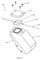
- FIG. 6A is a plan view depicting multiple fluidic channels of a cartridge of an embodiment
- FIG. 6B is an isolated view of a single fluidic channel of a cartridge of an embodiment
- FIG. 7A is a cross-section view of an internal standard (IS) module of an embodiment
- FIG. 7B is an exploded view of the components of an IS module of an embodiment
- FIG. 7C is an exploded perspective view of the internal components of an IS module of an embodiment
- FIG. 7D is an illustration of the transmission and reflection of a light source within an IS module of an embodiment
- FIG. 8A is a cross-section view of an electrochemiluminescence (ECL) detection system of an embodiment
- FIG. 8B is an exploded view of an ECL detection system of an embodiment
- FIG. 8C is a perspective view of a gasket of an ECL detection system of an embodiment
- FIG. 8D is a cross-section view of an ECL detection system of an embodiment
- FIG. 8E is a cross-section view of an ECL detection system of an embodiment
- FIG. 9 is a series of cross-section views of fluidic communications of a pump system of an embodiment
- FIG. 10 is a graphical representation of varying piston positions and resulting pressures of a pump system of an embodiment
- FIG. 11 is a graphical representation of the second derivative of the pressure signal in FIG. 10 ;
- FIG. 12 is a block diagram depicting a pump system of an embodiment
- FIG. 13 is a cross-sectional view of a pump and piston of a pump system of an embodiment
- FIG. 14 is a perspective view of external and internal barcode scanners of a diagnostic system of an embodiment
- FIG. 15 is a flow chart for a startup sequence of an embodiment
- FIG. 16A is a flow chart for an instrument-driven work flow of an embodiment
- FIG. 16B is a flow chart for an laboratory information system (LIS)-driven work flow of an embodiment
- FIG. 17 is a graphical representation of temperature monitored for two cartridges in Example 3 and 4;
- FIG. 18 is a graphical representation illustrating the difference in the incubation quality with and without applying different incubation set points in Example 3.
- FIG. 19 is a graphical representation illustrating differences in incubation quality in Example 4.
- bead(s) refers to many types of microscopic particles, such as superparamagnetic particles, magnetic microparticles, and magnetic nanoparticles.
- a bead may typically be spherical, though the shape is not limited to that of a sphere and may include other shapes like spheroid, irregular particles, cubes, irregular cubes, and disks.
- the size range may cover from 1 nanometer to 10 microns in diameter.
- standardized quantity refers to a known amount of a substance, where the amount might be mass, concentration, volume, number, or other physical quantity.
- the known amount may have been determined or traceable to a reference method, golden standard, NIST traceable standard or other.
- a known amount of a substance may also be determined by comparing an analytical result to a calibrator.
- fluorescence refers to the emission of light by a substance that has absorbed light or other electromagnetic radiation.
- fluorophore refers to a substance that is fluorescent.
- fluorescent label means a fluorophore used in the detection or measurement of fluorescence.
- a substance which is fluorescent yet detected by another detection method, such as ECL, is not a fluorescent label.
- a fluorescent label is only operative when measuring fluorescence.
- Fluorescent beads are the same as fluorescent labeled beads.
- assay construction refers to the step by step process of conducting an assay whether manual or automated. Assay construction typically involves laboratory operations such as pipetting, dispensing, metering, washing, free-bound separations, dialyzing, filtering, collecting, fractionating, diluting, mixing, incubating, and the like.
- fluidic element refers to a structure to hold, carry, or allow transport of a fluid.
- a fluidic element includes a pipe, channel, well, reservoir, conduit, valve, vent, flow path, disperser, pipette, funnel, filter, and passageway.
- fluidic communication refers to fluidic elements that are in fluidic communication if connected a channel, passageway, pathway, conduit, flow path or other fluidic element. Further, fluidic elements are in fluidic communication if connectable or transferable by a pipette. Further, fluidic communication includes adjacent or nearby fluidic elements which liquid may be dispensed or transferred by pipette between or from one to the other. For example any two wells of a 96 well microtiter plate are in fluidic communication.
- assay composition means the complete set or subset of the necessary reagents or substances required for an assay when combined.
- An assay composition may be the initial composition prior to assay construction, the composition immediately after initiating assay construction, the final mixture after assay construction, or the composition at any intermediate step of assay construction.
- Precision throughout this document refers to the reproducibility and repeatability of a characteristic. “Highly precise” means the characteristic variation is small over many observations of the characteristic. For example, the precision of cavity height Z in FIG. 8A refers to the variation of height Z observations seen after repeating the measurement on enough flow cells to statistically characterize the population.
- the diagnostic system generally includes a diagnostic instrument and a disposable vehicle, such as a cartridge, for carrying reagents, processed samples and other necessary materials used in diagnostic functions.
- FIG. 1 provides a schematic drawing illustrating an overview of the diagnostic system described in the present disclosure.
- the diagnostic system further includes features that are U.S. Food and Drug Administration (FDA) approved and/or have/can obtain(ed) a Clinical Laboratory Improvement Amendments (CLIA)-waived categorization.
- FDA U.S. Food and Drug Administration
- CLIA Clinical Laboratory Improvement Amendments
- FIG. 1 in operation of certain embodiments, a patient sample, such as venous whole blood, is drawn into a standard blood tube, which can then be inserted into a disposable cartridge, which can include barcodes or other identifying marks. Next, the cartridge can be loaded into an analyzer, such as a diagnostic instrument for processing. The results from the diagnostic instrument can be obtained and presented in as little as 8 to 15 minutes for up to ten different tests. The results of the test can be output via printer, laboratory information management systems (LIMS), or via other output devices.
- LIMS laboratory information management systems
- the processing time for an individual cartridge may be longer, for example, up to 20 or 30 minutes, depending on the amount of different tests being run on the individual cartridge. If there are fewer tests to be run on a single cartridge then less time may be expected to complete the processing cycle.
- the number of tests that can be run on an individual cartridge can vary as well. For example, a single cartridge can run a single test during a processing cycle or three tests or five tests, or any number of tests up to ten on a single cartridge for a single processing cycle of the diagnostic system.
- a diagnostic system includes a diagnostic instrument (See, e.g., FIG. 1 ) and a disposable cartridge (See, e.g., FIG. 2 ).
- a system may include additional or alternative diagnostic instruments, such as intermediate processors or non-compact components, or may use test cards, or reaction plates, or other disposable devices.
- the disposable cartridge can be used with the diagnostic instrument, which is preferably compact and self-contained, to perform diagnostic tests, such as measuring an immunoassay or a panel of immunoassays or detecting analytes, in a biological sample such as blood.
- the diagnostic instrument can run different diagnostic tests, such as assays, by using different disposable cartridges designed for each diagnostic test desired.
- a diagnostic instrument can include a motion assembly for positioning and accessing the cartridge, at least one fluidic tube, a pump for liquid handling, and an ECL detection system.
- the diagnostic instrument can also include a platform for a user interface, such as a touch screen, and/or at least one internal and at least one external barcode scanner for data entry.
- the diagnostic instrument also may provide safety and failsafe mechanisms throughout a workflow process.
- One such failsafe mechanism is an internal standard, which comprises both a module and a method for quantifying the bead recovery from the processing steps of a cartridge run independently of the ECL measurement.
- the at least one internal and external barcode readers can also be used as a failsafe mechanism.
- barcodes read on the disposable cartridge externally must match those read internally, to verify that the cartridge was not switched after the initial scanning.
- the diagnostic instrument may inform the user through the user interface by displaying an error message, for example.
- the diagnostic instrument has multiple aspects that are correlated to a disposable cartridge.
- a complementary and correlating cartridge contains all reagents and materials needed to perform a diagnostic test, such as, for example, run a particular panel of assays.
- the cartridge can include at least one needle, at least one fluidic channel, and at least one fluidic seal.
- the cartridge can have at least one reservoir for collecting all waste reagents from the assays or other diagnostic tests.
- Analyte specific reagents are essentially dry (e.g., lyophilized) to improve stability and can be located on the cartridge for use in the diagnostic test.
- liquid reagents such as an ECL read buffer and a pump priming fluid can be stored on the cartridge.
- the cartridge can have at least one needle that may be shrouded and onto which an operator can fit a standard blood tube.
- the disposable cartridge can be designed in such a way that all liquid waste will leave the diagnostic instrument via the cartridge.
- calibration and/or other assay information can be encoded on a cartridge in a machine-readable format, e.g., using a barcode.
- Some embodiments of a disposable cartridge in order to prepare and process a sample, e.g., on an ECL detection system, have various components and use various methods as described herein. These methods include, but are not limited to, methods of blood filtration (e.g., using tangential flow), methods for liquid-air transition detection in the channels of the cartridge, methods for aliquoting a clinical sample via segmented metering, methods for mixing reagents, methods for incubating the assay and washing the sample matrix away. These methods are all covered herein.
- the diagnostic system employs a closed fluidic pathway between the diagnostic instrument and the disposable cartridge.
- the closed fluidic pathway provides a pathway where a biological sample and necessary reagents are withdrawn from the cartridge using a substantially single direction of flow which returns used reagents and other waste materials to the cartridge.
- the connection of the blood tube to the cartridge facilitates access to the majority of the blood contained within the blood collection tube while maintaining a low profile within both the instrument and cartridge.
- both a multi-layer film structure and a multi-layer heat sealable film are used for sealing the top and bottom of the disposable cartridge.
- a multi-layer blood filtration assembly is used in a disposable cartridge, e.g., to remove red blood cells from the blood sample and/or to isolate blood plasma or serum.
- the diagnostic instrument 12 has a first probe 16 and a waste probe 18 , wherein the first probe 16 of the diagnostic instrument 12 can fluidically communicate with and connect reagents and materials within the cartridge 14 to the diagnostic instrument 12 .
- the waste probe 18 of the diagnostic instrument 12 can fluidically communicate with the at least one reservoir (not depicted) of the cartridge 14 to facilitate the disposal of waste materials thereby terminating the fluidic loop of the closed fluidic pathway.
- a closed fluidic pathway 10 that can communicate between a diagnostic instrument 12 and a disposable cartridge 14 (See, e.g., FIG. 2 ).
- a diagnostic instrument 12 is provided.
- at least one probe can be provided for introduction into a disposable vehicle, such as a cartridge 14 , thereby creating a means to withdraw diagnostic reagents and other necessary materials through a first probe 16 into a closed fluidic pathway 10 using a substantially single direction of flow which terminates at a waste probe 18 .
- the waste probe 18 provides a means to return used reagents and other waste materials to the disposable cartridge 14 .
- test materials can be withdrawn from the disposable vehicle, and after processing the diagnostic test, the test materials can be returned to the cartridge through the closed fluidic pathway thereby not returning the used materials through the fluidic path to interfere with subsequent tests.
- the substantially single direction of the flow and the closed-loop configuration serve to reduce the potential for carryover between tests. Opportunities for carryover can be further reduced by transporting fluids through a single non-branching fluidic path.
- a closed loop fluid system for use in processing in vitro diagnostic tests.
- the closed fluidic pathway 10 originates and ends with two separate probes where a first probe 16 facilitates the withdrawal of test materials from a disposable vehicle, such as a cartridge 14 , and a waste probe 18 facilitates the return of waste materials to the cartridge.
- fluid flow is substantially single directional in order to reduce the potential for carryover between diagnostic tests.
- FIG. 2 provides an embodiment of a diagnostic system having a closed fluidic pathway 10 comprising a diagnostic instrument 12 having at least one probe 16 , 18 ; at least one fluidic tube 20 ; a non-ECL detection system (or an IS module) 22 ; an ECL detection system 24 ; a pump 26 ; and a motion assembly (not depicted).
- the closed fluidic pathway 10 also comprises a disposable cartridge 14 having at least one needle (not depicted); at least one reservoir (not depicted) at least one fluidic seal (not depicted); and at least one fluidic channel (not depicted), wherein the closed fluidic pathway 10 substantially flows in one direction in a loop fluidically connecting the diagnostic instrument 12 and the disposable cartridge 14 .
- the closed fluidic pathway can have a substantially single directional flow which can reduce a potential for carryover between diagnostic tests.
- the motion assembly (not depicted) can have two axes of motion and can further comprise an incubator (not depicted), which can be a multi-zone incubator.
- the incubator can achieve uniform and precise incubation of a biological sample within the cartridge.
- the fluidic path of the closed fluidic pathway flows from a diagnostic disposable, such as a cartridge 14 , which contains all materials necessary to process the diagnostic test, through a first probe 16 .
- All the reagents and other test materials enter the fluidic path at the first probe 16 and flow to and through at least one detection instrument 22 , 24 in which the diagnostic test is processed.
- the test data is obtained after the reagents pass through the fluidic path and into a pump 26 .
- the processed sample and waste materials leave the pump 26 through a continuation of the fluidic path and return to the disposable cartridge 14 through the waste probe 18 .
- the flow of fluid is substantially single directional from the cartridge 14 , through the at least one detection instrument 22 , 24 , through the pump 26 , and back to the disposable cartridge 14 .
- the substantially single directional flow can reduce test to test carryover.
- the opportunity for carryover increases in the pump 26 as the pump likely represents a discontinuity in the geometry of the flow path, therefore maintaining a buffering length of fluidic path between the detection instruments and the pump, greater than the volume of any potential backflow is desirable to prevent carryover.
- a fluidic pathway of a closed fluidic pathway can be defined by a first probe 16 , which can be formed from a hollow needle, and which can begin a fluidic pathway for a diagnostic system.
- the fluidic pathway of the closed fluidic pathway 10 can have a first tube 20 a establishing fluidic communication with and having the same inside diameter as the first probe 16 .
- At least one detection instrument 22 , 24 can encompass a fluidic pathway that is matched at its origin to the inside diameter of the tube and establishing fluidic communication therewith.
- a second tube 20 b can establish fluidic communication between the at least one detection instrument 22 , 24 and a pump 26 , having the same inside diameter as the fluidic pathway at the exit of the detection system and at the entrance of the pump 26 .
- the pump 26 can provide motive force for fluidic motion within the fluidic pathway, having a logical entrance and exit for fluidic flow.
- a fluidic pathway continues in the form of a third tube 20 c establishing fluidic communication with and having the same inside diameter as the exit of the pump 26 and a waste probe 18 .
- the waste probe 18 formed from a hollow needle, constitutes the end of a fluidic pathway.
- a fluidic communication between the diagnostic instrument 12 and a disposable cartridge 14 can be established when a first probe 16 of the diagnostic instrument 12 contacts and enters into at least one fluidic reservoir 32 on the disposable cartridge 14 by piercing a fluidic seal 30 .
- the first probe 16 can then establish fluidic communication with various containment areas within the disposable cartridge 14 in order to extract test materials and/or process materials within the disposable cartridge 14 .
- reagents can be aspirated from a reagent well 32 by the first probe 16 for processing during a diagnostic test run.
- the waste probe 18 can also establish fluidic communication with various containment areas within the disposable cartridge 14 in order to return waste materials to waste containment areas 34 within the disposable cartridge 14 .
- the substantially single directional flow of the fluidic system is depicted in FIGS. 2 and 3 by the arrows.
- the fluidic system creates a substantially single-direction fluidic flow from the first probe 16 through the first tube 20 a , the at least one detection instrument 22 , 24 , the second tube 20 b , the pump 26 , the third tube 20 c , and terminates at the waste probe 18 .
- Test materials can be processed along this route beginning within reagent wells 32 and other containment areas of the disposable cartridge and returning all waste materials to waste containment areas 34 of the disposable cartridge.
- a cartridge 14 can have an initially empty chamber is provided to receive waste materials from the initial diagnostic test.
- reagent is removed from its designated reagent containment chamber for use in processing that test.
- waste material from that test is returned to the reagent chamber emptied during the prior test.
- a fluidic system is formed of one or more segments of fluidic pathway typically, but not necessarily, in the form of tubing.
- inside diameters of each segment of the fluidic pathway are matched at the junctions of each segment in order to mitigate potential carryover traps.
- the fluidic pathway begins with a first probe 16 , preferably, but not necessarily with a non-coring tip profile such that it may pierce a foil or a multi-layer film structure such as a septum 30 on a diagnostic disposable cartridge 14 housing thus establishing fluidic communication between the fluidic system and the disposable cartridge 14 .
- the next segment establishes a fluidic pathway to at least one detection system 22 , 24 .
- This fluidic pathway segment may be a part of or separate from the segment such as a tube 20 a passing through the at least one detection instrument 22 , 24 .
- the at least one detection instrument 22 , 24 comprises the next segment of the fluidic system, where detection is performed without the sample leaving the fluidic pathway.
- the next segment of the fluidic pathway may be a separate item such as a tube 20 b , or may be incorporated into either the detection system or the pump 26 , as long as it establishes fluidic communication between the at least one detection instrument 22 , 24 and the pump 26 . If necessary, additional pieces of tubing or other suitable fluidic pathway materials may be incorporated to connect multiple detection systems.
- the next fluidic pathway establishes fluidic communication between the pump and the waste probe 18 .
- the fluidic pathway terminates with a waste probe 18 , preferably, but not necessarily with a non-coring tip profile such that it may pierce a foil or a multi-layer film structure, such as a septum 30 , on a diagnostic disposable cartridge 14 .
- the waste materials from the diagnostic test can be returned to otherwise empty chambers 34 of the disposable cartridge 14 .
- Various portions of the fluidic system may be comprised of separate pieces that make up the fluidic pathway or may be combined, for example, to further reduce potential for carryover between diagnostic tests. Examples include but are not limited to: (a) combining the first probe and the first tube; (b) combining the third tube and the waste probe; (c) having one continuous tube encompassing the first probe and the balance of the fluidic path terminating at the pump; and/or (d) combining the detection system(s) and the pump into a single manifold encompassing the fluid pathways between them. It is contemplated that the arrangement of the internal components within the diagnostic instrument can be configured to satisfy desired standards, including size, weight, shape, aesthetic appearance.
- Certain embodiments provide a method for achieving a uniform and precise incubation of patient plasma with the selected reagents, in a disposable cartridge-based point of care system to facilitate the binding of the detection reagents to a particular antigen, for example, those that may be present in a biological sample such as a patient's plasma.
- a biological sample such as a patient's plasma.
- an incubator single or multi-zone
- precise incubation with temperature uniformity can be achieved in such a manner that the effect of variations of the storage temperatures for the cartridge prior to use. Unwanted variations of the operating temperature of the instrument are also minimized, and do not affect the measured concentrations of analytes such as antigens in the biological sample.
- some embodiments ensure that if the same biological sample or patient's blood is analyzed in a cartridge that was stored in different temperatures, the result will still show the same level of concentration of antigen or analyte activity. Likewise, other embodiments ensure that if the same patient's blood is analyzed in an instrument that is being operated in different temperatures, the result will still show the same level of concentration of antigen or analyte activity.
- the amount of binding that takes place i.e., activity of reagents, sample and analytes
- the amount of measured antigen is directly related to the amount of binding that takes place.
- FIG. 4A is an illustration depicting an incubator plate 40 , a heater 42 , a sensor 44 , and a control loop 43 used in measuring the starting temperature of the cartridge 14 and providing a temperature control mechanism for the incubation of the sample in the cartridge 14 .
- FIG. 4B provides a perspective view of the spatial relation of the cartridge 14 and the incubator 46 comprising the individual components of heater 42 , sensor 44 , incubator plate 40 within a diagnostic system, and wherein the surrounding components of the diagnostic instrument are not presently depicted.
- a method of temperature control of a cartridge 14 comprises measuring with a sensor 44 the starting temperature of the cartridge 14 containing a biological sample and at least one reagent; adjusting a set of predetermined pre-incubation parameters depending on the measured starting temperature; heating with a heater 42 the cartridge 14 to a target temperature; maintaining the target temperature for a period of time equal to or less than the time it takes to complete a diagnostic test; intermittently measuring the temperature of the disposable cartridge 14 throughout the segment of time of the diagnostic test to ensure temperature control; and heating at least a portion of the disposable cartridge 14 to the target temperature when the temperature of the disposable cartridge 14 is less than the target temperature.
- starting temperature refers to the initial temperature of the bottom of a cartridge 14 the instant the cartridge 14 is inserted into the instrument 12 .
- the at least one heater 42 and/or at least one temperature sensor 44 can detect the cartridge 14 temperature.
- the heater 42 and temperature sensor 44 can be on a printed circuit board, which is integrated into a motion assembly (not depicted) of the diagnostic instrument.
- the same temperature sensor 44 can be used to measure the cartridge 14 temperature and used in the closed loop control to maintain the temperature of the cartridge 14 .
- different temperature sensors can be used to measure the cartridge 14 temperature and used in the closed loop control to maintain the temperature of the cartridge.
- the method of incubation can further comprise repeating the incubation method for the duration of the diagnostic test until completion.
- “Closed loop control” in this document refers to a control system with one or more sensors providing feedback signals to the control system that are used to modulate the system response.
- the temperature control system shown in FIG. 4A modulates the incubator heater power based on output of temperature sensor 44 .
- the temperature sensor 44 provides the feedback signal that closes the control loop. Contrast this to “open loop control” systems, where no feedback signal is used to modulate the system response.
- the incubation also can be performed by a multi-zone temperature control incubator.
- the multi-zone temperature control incubator can operate under independent control loops (See, e.g., FIG. 5 ).
- the incubator can achieve uniform and precise incubation of a biological sample within the cartridge 14 .
- the multi-zone temperature control incubator can provide a more uniform temperature control along the body of the cartridge. This will allow for multiple measurements of the same sample for multiple tests, by allowing a uniform temperature to be maintained among the multiple measurements. Using the multi-zone temperature control incubator further improves temperature uniformity and precision during processing and operation of the diagnostic system.
- a biological sample such as a patient's blood
- a filtration module An example of a suitable filtration module is described in the co-pending International PCT Application No. PCT/US2012/067041, filed on Nov. 29, 2012, and which is herein incorporated in its entirety.
- FIG. 6A illustrates the bottom of a cartridge, showing multiple fluidic channels 50 arranged into single cartridge assay replicates (CAR) 54 , which represent independent channels in a cartridge 14 that can process different tests for the same patient.
- CAR cartridge assay replicates
- FIG. 6B A single CAR is shown in FIG. 6B , holding a sample 52 in a fluidic channel 50 .
- the metered plasma sample then can be moved and mixed with reagents, such as with lyophilized reagents.
- the mixture then can be moved to a location in the channel and parked.
- the bottom of the cartridge where the mixed plasma makes contact can be a thin film, such as a bottom seal that is transparent.
- the cartridge 14 can be positioned on a flat surface of an incubator which is comprised of various components including an incubator plate 40 that can be heated by a heater 42 usually positioned under the incubator plate 40 .
- a temperature sensor 44 can be located at several varying locations on the heater 42 . It is contemplated that more than one sensor may be incorporated into the incubator.
- the sensors 44 can measure the temperature of the incubator plate 40 that is heated by heater 42 .
- the sensor 44 measurements can be monitored by the Central Processing Unit (CPU) (not depicted), and a closed loop proportional-integral-derivative (PID) control can be used to maintain the temperature of the incubator 40 at the target temperature for a period of time.
- the period of time for incubation of the cartridge 14 can be equal to or less than the time it takes to run a complete diagnostic test on the cartridge.
- the incubation occurs as an initial step in the diagnostic system processing and is used to prepare the sample before and during sample measurements take place within the diagnostic instrument. Thus, depending on how many tests are being run off of any given cartridge, the time period for incubating the cartridge will span at least the time of processing all the tests on a cartridge.
- measuring the starting temperature of the cartridge can be achieved when, after a cartridge 14 is inserted, the heater 42 is momentarily shut off.
- the rate of the incubator plate's 40 temperature loss is computed, for example, by monitoring the same sensor 44 that is being used to control the temperature.
- the rate of temperature loss is related to the rate that heat transfers from the incubator plate to the cartridge 14 .
- the rate that heat transfers from the incubator plate 40 to the cartridge 14 is related to the temperature difference between the incubator plate 40 and cartridge 14 .
- the duration of the Idle (Boost) Target Temperature is adjusted accordingly.
- boost refers to an initial application of temperature for a certain time and at a certain location on an incubator that can be used to heat up the cartridge.
- the incubator heats up the cartridge by applying a higher incubation temperature set point than a normal incubation temperature set point for a duration of time at a location on the incubator.
- the diagnostic instrument 12 when there is no cartridge inserted, can maintain the temperature of the incubator plate 40 at an idle target temperature.
- the diagnostic instrument 12 can start detecting the temperature of the cartridge 14 , by measuring with a sensor 44 the rate of the temperature drop of the incubator plate 40 due to the different temperature of the cartridge 14 .
- the drop rate (calculated by the CPU) can be used to determine the starting temperature of the cartridge.
- the drop rate can then be used to select the duration (from a pre-constructed table or an equation) that the cartridge can be kept on the incubator plate 40 at the Idle (Boost) Target Temperature.
- the presently disclosed method of temperature control ensures, among other things, that all samples start incubation at the same temperature regardless of cartridge storage temperature and that all samples receive the same amount of incubation activity regardless of cartridge storage temperature.
- a multi-zone incubator such as that shown in FIG. 5 , allows the diagnostic instrument to heat up the cartridge while, for example, filtering blood without affecting the temperature of the portion of the incubator that is not being cooled off by the cartridge.
- the multi-zone incubation is achieved by having two separate heaters 42 a , 42 b under the incubation plate 40 . Each can have its own temperature sensor 44 a , 44 b . Each can have its own closed loop control 43 a , 43 b of the kind previously described.
- the cartridge while filtering blood can be positioned on one of or part of both of the incubation zones 41 a , 41 b depicted in FIG.
- the multi-zone incubator does not require an added temperature sensor to measure the starting temperature of the cartridge that is coming into the instrument from its storage temperature.
- the same temperature sensor 44 a , 44 b for example, the thermistor 44 a , 44 b in FIG. 5 , that is in the feedback control loop controlling the incubator is also used for determining the starting temperature of the cartridge in this embodiment.
- An IS is a substance that is added in a constant quantity to samples and calibration standards in an assay or analysis.
- An IS is a substance that is very similar, but not identical to the substance of interest in the sample. The effects of assay construction should be the same for the IS as the substance of interest.
- One purpose of an IS is to identify failures that might occur during assay construction. As such, the method to implement the IS operates as a failsafe mechanism. Another purpose of an IS to correct for normal variability in assay construction. As such, the method to implement the IS operates as a means to improve precision and accuracy.
- a device such as a cartridge, which contains all reagents and materials needed to perform a diagnostic test, such as an assay.
- a diagnostic test such as an assay.
- one reagent is beads. This substance is used in the method to construct a diagnostic assay.
- the bead surface is the bound phase for a binding assay.
- the quantity of label bound to the bead is measured by ECL detection and the ECL signal to concentration.
- the quantity of beads present during assay construction is critical to the overall performance of the diagnostic instrument.
- assay construction involves various processing steps. These may include free-bound separations, which generally consist of magnetic collection of the beads and bead wash steps. Any variability in the quantity of beads after such processing is undesired, as this may in some cases reduce precision and accuracy, in other worse cases cause an error in the reported result of the diagnostic assay.
- fluorescent labeled beads are employed as an IS to prevent errors, and/or improve precision and accuracy in the reported results for ECL-based diagnostic assays.
- fluorescent labeled beads process identically to ECL labeled beads. As such, any variability experienced by ECL labeled beads are also found within the quantity of fluorescent beads. For example, if during magnetic collection, 95% of the ECL labeled beads in the sample were captured onto a magnet surface, then 95% of the fluorescent beads were likewise captured onto the magnetic surface.
- fluorescent labeled beads are employed as an IS to measure bead recovery after assay construction for ECL-based diagnostic assays.
- Bead recovery is the relative quantity (or percentage) of beads measured compared to the quantity of beads intended to be used in assay construction. For example, if 100,000 beads were initially contained within the diagnostic instrument, and upon completion of assay construction, 95,000 beads were measured, then bead recovery would be 95%.
- Bead recovery is derived by comparing the fluorescence signal from the IS to the fluorescence signal from a standardized quantity of fluorescent beads.
- Fluorescent beads can be labeled by coating fluorophore onto the bead surface. Coating can involve many different chemical or physical methods. Any one skilled in the art of conjugation can readily coat beads with fluorophore. Further, fluorescent beads can be alternatively be labeled by incorporating fluorophore within the interior of the bead. Further the beads can be labeled by both of the above methods.
- IS can be comprised of fluorescent labeled beads, or fluorescent labeled and ECL labeled beads.
- the sample would contain a mixture of fluorescent labeled beads and ECL labeled beads.
- the sample would contain beads with both fluorescent and ECL label on the same bead.
- Fluorophore can be allophycocyanin (APC) with an absorption maximum of 652 nm and an emission maximum 658 nm.
- the fluorophore can be Sky Blue (Spherotech) with an absorption maximum of 660 nm and an emission maximum 705 nm.
- the beads can be superparamagnetic beads such as InvitrogenTM Dynabeads® M-280 Streptavidin or SPHEROTM Magnetic Particles.
- the ECL label can be ruthenium (II) tris(2,2′-bipyridine).
- the diagnostic instrument of the diagnostic system includes a measurement and detection module, called an internal standard (IS) module, that is independent and distinct from an ECL detection system.
- the ECL detection system measures an ECL signal obtained from ECL labeled beads.
- the IS module and IS do not interfere with the ECL measurement.
- the IS module is a flow cell that measures fluorescence.
- the IS module performs a non-contact measurement to quantify fluorescence, and hence bead recovery. It is contemplated that the IS module can be in a separate location from the location of the ECL measurement, i.e., separate from the ECL detection system.
- the IS measurement also can occur at a different time during an individual cartridge processing cycle, for example, prior to or at the same time as the ECL measurement during an individual cartridge processing cycle.
- a fluidic pathway can include any part of the diagnostic system where fluids can flow and is not limited to a tube structure such as the tubing assembly.
- the IS module uses a light source, such as a laser, laser diode, or light emitting diode to excite fluorescent labeled beads present within the sample moving through the IS module.
- the fluorescent labeled beads emit fluorescent light that can be accurately measured using a light detector such as a photodiode or photomultiplier tube.
- the measured light fluorescence signal can be compared with the fluorescence signal obtained for a known number of fluorescent labeled beads, and a percentage bead recovery calculated.
- FIG. 7A is a cross-section view of an IS module of an embodiment.
- FIG. 7B is an exploded view of the components of an IS module of an embodiment.
- FIG. 7C is an exploded perspective view of the internal components of an IS module of an embodiment.
- an IS module 60 is a flow-through cell having a housing 62 with a tubing assembly 64 and at least one opening 63 in the housing 62 to facilitate the entry and exit of the tubing assembly 64 to and from the IS module 60 , as shown in FIGS. 7A-7C .
- the IS module can also include a first photodiode 74 and a second photodiode 75 connected to and powered by a printed circuit board (PCB) 71 .
- PCB printed circuit board
- a laser mount 70 holds a laser 67 and an excitation filter 68 , which is used to remove light at wavelengths may interfere with fluorescence measurement.
- the laser mount 70 also has a small aperture (not depicted) at one end through which the laser light exits as it is guided by a light pipe 69 .
- the light pipe 69 directs the laser light to a portion of the tubing assembly 64 . When the laser light is incident the tubing assembly, both the laser light and laser-induced fluorescent light can be detected by the first 74 and the second 75 photodiodes.
- Light pipe 69 is secured to laser mount 70 using screw 76 .
- the IS module 60 can be formed from housing members including a housing 62 , at least one panel 66 and at least one cap 61 .
- the at least one cap 61 also is removable to aid in assembly of the IS module 60 .
- the at least one panel 66 and the at least one cap 61 can be removable and therefore securable to the housing 62 with standard fasteners 65 .
- Screw 78 secures laser 67 to laser mount 70 .
- the at least one cap 61 can be positioned over an uncovered portion of the housing 62 through which the tubing assembly 64 passes.
- the tubing assembly 64 can be made of a variety of suitable plastic materials.
- the tubing assembly 64 can be made from a clear FEP (fluorinated ethylene propylene) with an internal diameter of 0.020′′.
- the tubing assembly can be held in place with vacu-tight fittings (not shown) on either side of the housing 62 .
- black heat shrink (on the probe side) and black FEP tubing (on the ECL detection side) covers the clear FEP tubing.
- the tubing assembly can be used to light seal the tubing assembly such as applying an opaque sleeve and coating, painting or tinting the tubing assembly in opaque light blocking materials.
- the sizing of the aperture 63 in housing 62 correlates to the size of the tubing.
- the opening 63 is big enough to allow the tubing assembly 64 to pass through, yet small enough that it can be easily light sealed with a fitting or gasket.
- a gasket 64 a can be positioned within a recess of the housing 62 .
- the gasket 64 a can be formed to fluidically seal the tubing assembly 64 as it passes through the at least one opening 63 in the housing 62 .
- the gasket 64 a also functions to form a light tight seal for the contents of the tubing assembly 64 , particularly during the IS measurement.
- the housing 62 can be comprised of an opaque material that is sturdy and supportive. Suitable materials include, but are not limited to, aluminum, steel, or brass.
- the inside surfaces of the housing can be painted black or coated with a seal or tint to absorb stray light that may find a way into the IS module. It is important to have a light tight surrounding to receive an accurate light reading within the IS module.
- the light source can be derived from a laser 67 .
- the laser 67 can fit inside a drilled out cylindrical hole of the laser-mount 70 , which in turn is positioned in the housing 62 , an example of which is shown in FIGS. 7A and 7B .
- Light from laser 67 is filtered using excitation filter 68 which is used to remove light at wavelengths may interfere with fluorescence measurement.
- excitation filter 68 which is used to remove light at wavelengths may interfere with fluorescence measurement.
- the laser light before striking the tubing assembly 64 , the laser light passes through a 632 nm band pass filter, light pipe 69 and exits the IS module through a round 0.065′′ aperture. It is contemplated that depending on the fluorophore, different lasers can be used within the IS module. For example, when APC or Sky Blue is the fluorophore, the IS module can employ a 635 nm laser light source.
- the printed circuit board 71 can be mounted to the laser mount 70 and can hold the first and second photodiodes 74 , 75 (see, e.g., FIGS. 7A and 7B ).
- the first photodiode 74 detects the fluorescent light.
- the second photodiode 75 measures the power of the laser light.
- the first and second photodiodes 74 , 75 are mounted on opposite sides of a detector mount 73 attached to the printed circuit board 71 .
- Emission filter 77 is attached to first photodiode 74 , and used to remove light of wavelengths that may interfere with the fluorescence measurement.
- emission filter 77 is a color glass filter RG695.
- the first and second photodiodes are mounted on opposite sides of a diode mount attached to the printed circuit board. Both the fluorescent light as well as the laser light can be detected with photodiodes which converts the light into a measurable electrical signal through connector 72 . As the laser strikes the tubing assembly the first photodiode measures and detects the fluorescent light emitted by the fluorescent beads flowing through the tubing assembly. Concurrently, the second photodiode measures and detects the laser light originating from the tubing assembly.
- FIG. 7D provides a depiction of optical path of the laser light within the IS module in an embodiment.
- the light from laser 67 passes through excitation filter (not shown) and is guided through the light pipe (not shown) onto the tubing assembly 64 containing the sample.
- the laser light beam is incident the tubing assembly at a 45° angle.
- the photodiodes are oriented 45 degrees respect to laser beam, and 90° in rotation with respect to each other around the tubing.
- Certain embodiments provide a fluorescence based, non-interfering method to detect and measure ECL bead recovery, if any, during the processing of a cartridge, comprising the steps of illuminating with a light source a processed sample flowing through a tubing assembly; wherein the sample contains fluorescent labeled beads and ECL labeled beads and the light source is of a specific wavelength to excite the fluorophore; detecting fluorescent light emitted by the fluorescent beads flowing through the tubing assembly; converting the fluorescent light into measurable electrical signals; processing the electrical signals to calculate ECL bead recovery by comparing the fluorescence signal to a fluorescence signal from a standardized quantity of fluorescent bead.
- the IS method provides a failsafe mechanism to prevent reporting erroneous results.
- the IS method provides an improvement is precision and accuracy results.
- ECL Electrochemiluminescence
- Electrochemiluminescence is a quick and sensitive technique. It has been described in detail in the following U.S. Pat. Nos. 5,714,089, 6,165,729, 6,316,607, 6,312,896, 6,808,939, 6,881,589, 6,881,536, and 7,553,448, all of which are herein incorporated in their entirety. It is contemplated that a label is an ECL label and the presence of the bound labeled molecule is detected by ECL. ECL signals are generated by a redox reaction between an ECL label with a substrate. In certain embodiments the ECL label is a ruthenium-containing reagent.
- ECL label Tris(bypyridine)ruthenium(II) [Ru(bipy)3]2+, also referred to as TAG.
- the substrate is tripropylamine (TPA).
- TPA tripropylamine
- ECL technology is advantageous in that it is a regenerative process, in which a luminescent signal can be generated by a reaction involving a ruthenium (Ru) conjugate at the surface of an electrode (DEAVER, DR., “A New Non-Isotopic Detection System for Immunoassays,” Nature 377(6551):758-760 (1995)).
- a magnet usually below an electrode will attract the magnetic beads, pulling down the Ru-tagged complex near the electrode.
- the Ru can then be oxidized.
- Oxidized tripropylamine (TPA) reacts with the oxidized Ru, which then emits a photon.
- the redox reaction between Ru and the substrate tripropylamine (TPA) that occurs only in the electric field near the electrode is a regenerative process, which allows for an ECL signal that undergoes amplification over time. Because photons can only be generated near the electrode surface, electrochemiluminescence only occurs when the Ru is brought into proximity with the electrode by the magnet; thus, background is reduced.
- Some embodiments provide a new and improved ECL detection system for diagnostic applications.
- the improvements include, but are not limited to: (I) improvements in the design and use of gasket materials by which a precisely sized measurement containment area is established in order to increase the accuracy and precision of sample measurements; (II) a novel use of differential compliance to enable mounting and precise spacing of two or more electrodes while also creating feature seals to prevent leaking; and (III) a new method to accomplish light sealing of an enclosure by means of a substantially opaque printed circuit board while at the same time permitting electrical connections and/or the introduction of other components between the inside and outside of the light enclosure; (IV) a new method to accomplish light sealing of an enclosure by using an opaque material beneath enclosure openings, such as, fluidic ports that connect fluidic pathways inside and outside of the light enclosure.
- the diagnostic system includes an ECL detection system having an ECL detection module (also referred to as a flow cell) with fluidic and electrical connections to the closed fluidic pathway, such as that previously discussed (not depicted).
- an ECL detection system can include an ECL detection module 80 having an enclosure made of a top 82 and a base 84 , wherein the upper surface of base 84 is flat and forms a working surface. The top 82 can be attached to the working surface of base 84 , thereby forming a cavity of precise height Z.
- the ECL detection module 80 also can have a first electrode 86 and a second electrode 87 that are stacked upon each other and separated by a first gasket 88 .
- the base 84 can support the first electrode 86 and the electrode/gasket stack.
- First gasket 88 is sufficiently thick and compliant to require forceful closure of top 82 onto base 84 and presses electrodes 86 and 87 firmly against the cavity walls, and thereby creates a precise predetermined separation gap H between the first and second electrodes 86 , 87 .
- a change in compliance can be associated with a change in thickness or a change in hardness between two different materials, or a change in geometry of the compressed area between two different materials or two of the same materials.
- compliant can refer to the displacement of material for a given load and it can also refer to the softness of a material wherein a material can be more compliant due to the material being softer.
- a cut out opening 87 a in the second electrode 87 permits light to pass through the electrode during the ECL measurement.
- the cut out 87 a in the second electrode 87 aligns with a transparent window in top 82 , such that light from the ECL reaction can be measured by the photodetector 82 a .
- Fluids must enter and exit the measurement containment area to setup the ECL reactions and flush the cell of prior reactants.
- FIG. 8A shows fluid inlet and outlet ports 82 b and 82 c aligned to two additional apertures 87 b and 87 c in electrode 87 .
- the ECL detection system also includes a printed circuit board 90 that is positioned next to the base 84 and connects the components within the ECL detection system electrically.
- the first and the second electrodes 86 , 87 can be made from a variety of conductive noble metals, including, but not limited to, platinum, gold, iridium, palladium, osmium, and alloys thereof.
- the first and second electrodes 86 , 87 may also be made of conductive non-metals, such as carbon.
- the top 82 can be made from a variety of durable materials, including, but not limited to, acrylic, polyether ether ketone and acetal polymers.
- the base 84 can be made from a variety of durable materials, including, but not limited to aluminum, copper and stainless steel.
- the gasket 88 has an elongated cutout 88 a shown in FIG. 8C .
- the elongated cutout 88 a creates a measurement containment area (i.e., the ECL reaction chamber).
- the measurement containment area must be sealed liquid tight and airtight, so it is desirable to have a gasket that is made from a compliant material that seals against the electrode surfaces.
- gaskets can be made from a variety of compliant materials including, but not limited to, perfluoroelastomers such as Chemraz 631 or Kalrez 2037, fluoroelastomers, nitrile and silicone rubbers, and polymers such as polytetrafluorethylene (PTFE) and polychlorotrifluoroethylene (PCTFE). Electrode surfaces are only exposed to chemical fluids within the gasket cutout 88 a , and consequently only this portion of the electrode surfaces are active during ECL reactions.
- perfluoroelastomers such as Chemraz 631 or Kalrez 2037
- fluoroelastomers fluoroelastomers
- nitrile and silicone rubbers nitrile and silicone rubbers
- polymers such as polytetrafluorethylene (PTFE) and polychlorotrifluoroethylene (PCTFE). Electrode surfaces are only exposed to chemical fluids within the gasket cutout 88 a , and consequently only this portion of the electrode surfaces are active during ECL
- Consistent ECL reactions and measurements among instruments requires the measurement containment area geometry and electrode spacing to be uniform and precise from flow cell to flow cell.
- the cut-out or gasket opening 88 a distorts laterally and dimensions L and W are diminished from the uncompressed state.
- the cavity pocket depth Z in FIG. 8A is precision machined in top 82 to ensure uniform spacing between the electrodes 86 , 87 and consistent clamping of gaskets.
- the thickness of electrodes 86 and 87 are made to precision tolerances.
- Compliant materials when compressed across their thickness, spread laterally. Thus, cut-out or gasket opening 88 a closes down as gasket 88 is clamped between the electrodes. Limiting the final clamped dimension of cut-out 88 a requires tight control of the gasket thickness, and can minimize variations of the measurement containment area geometry.
- Compliant materials used to create gaskets are often fabricated from sheets or slabs that are molded, extruded, calendered or cut into appropriate thicknesses by slicing or skiving. However, the gasket thickness precision is generally inferior to the tolerances of other rigid components used in the system.
- Gaskets of varying thicknesses cut to the same inside profile 88 a will, when compressed, result in different-sized internal areas, which can in turn result in undesirable ECL signal variations when used in an ECL detection system. It is desirable to improve the measurement containment area geometry precision by sizing the gasket cutout 88 a in proportion to the thickness of the gasket, such that when the first gasket is constrained to a fixed compression distance, the desired size measurement containment area is achieved. Sizing the inside profile 88 a based on the thickness of the gasket raw material, while taking the compressive characteristics of the material into account, results in maintaining the compressed gasket cutout area to an acceptable tolerance.
- the precise, predetermined separation gap H provides the desired accuracy of an ECL measurement.
- the compliant gasket provides expansive force to maintain a precise distance between the electrodes as is required in order to obtain precise ECL measurements.
- ECL measurements depend on both the distance H between the electrodes and the area of the exposed portion of the electrodes, the cutout in the gasket that forms the measurement containment area must be precise.
- the size of the cutout that will form the measurement containment area is adjusted based on the thickness T of the raw material of the first gasket and the compressive characteristics of the raw material.
- the first gasket 88 is depicted as being formed from a raw material of nominal thickness having a thickness tolerance of ⁇ 0.002 in.
- This depicted first gasket requires that a different size L ⁇ W cutout be made for each 0.001 in. of thickness variation in order to achieve adequate precision of the compressed cutout area.
- the L ⁇ W cutout dimensions could vary continuously with the gasket material thickness deviation from nominal thickness. Gasket material characteristics and thickness tolerances range widely, and the particular design requirements of the measurement device will determine how the gasket cutout dimensions must be adjusted to achieve adequate precision of the clamped, in situ gasket cutout area.
- a first (cell) gasket 88 seals the perimeter of the measurement containment area against the electrodes, but no seal is shown around the window aperture 87 a or the fluid port apertures 87 b or 87 c in electrode 87 .
- These areas are often sealed by cementing the second electrode into the body with epoxy, acrylic or other permanent adhesives. The adhering process is slow, messy, difficult and time consuming. In addition, the cemented joints erode away during flow cell use, causing the second electrode to delaminate or develop leaks and servicing or replacement of individual components is made difficult or impossible.
- Some embodiments do not require adhesives to create the fluidic seals within the ECL detection system. These embodiments also maintain the precise positioning of the components relative to each other as is required to make an ECL detection system precise and accurate.
- a second gasket 89 backs at least one of the electrodes in order to establish fluidic sealing.
- the second gasket 89 can be more compliant than and have a lower compressive force than the first gasket 88 so as not to change the separation gap H set for the first and second electrodes 86 , 87 by the first gasket 88 .
- This second gasket 89 eliminates the requirement to adhere the electrodes to the enclosure with adhesives such as epoxy, improving the ease of assembly, the reliability and longevity of the seal and makes servicing components practical.
- FIG. 8B shows an example of how the ECL detection module 80 can be enclosed in an opaque case 81 and the base 84 to exclude ambient light that would otherwise interfere with detection of the internal low level ECL light signals.
- the opaque case 81 and base 84 have openings for the required fluidic and electrical connections to the flow cell, and these openings must also exclude ambient light.
- the fluidic openings A and B of opaque case 81 are depicted on top of the ECL detection module 80 .
- the fluidic tubing and fittings that fit to these openings are designed to transport fluids, and often have limited ability to block ambient light. Ambient light travelling through the fluidic tubing and connections may enter the ECL detection module 80 through the fluidic openings A and B of opaque case 81 , and pass through the inlet and outlet ports of the opaque top half of flow cell top 82 seen in FIG. 8B which blocks this light from reaching the detector.
- the opaque enclosure of the ECL detection system can further include at least one opening 94 to permit electrical connections to be introduced into the enclosure (as shown in FIG. 8E ).
- the electrical connections 93 are provided by the printed circuit board (PCB) 90 .
- the printed circuit board 90 may be made from an inherently opaque material, or can have an opaque coating 91 , such as solder mask or screen printed layers, on its surface to prevent light leakage into the enclosure through the at least one opening 94 . Examples of inherently opaque materials and opaque coatings include black glass fiber/epoxy laminates and black matte liquid photo-imageable solder masks meeting IPC SM 840 Qualification and Performance Standards for permanent solder mask.
- the printed circuit board 90 can also include an internal or external conductor layer 92 which can further block undesired light entry.
- an ECL detection system 80 comprising an enclosure having a top 82 and a base 84 .
- a stack is formed within the enclosure with a first electrode 86 , a second electrode 87 and a first gasket 88 sandwiched between the electrodes.
- a cavity or gap formed by the pieces of the enclosure define the desired gap (Z) in which to house the electrode/gasket stack, thereby establishing the distance between the electrodes.
- the first gasket 88 made of compliant material, has a thickness greater than the desired distance between the first and second electrodes 86 , 87 .
- a measurement containment area of precise size is defined by a cut-out 88 a once the first gasket 88 is compressed.
- the first gasket 88 is fabricated with a cut-out 88 a that has been sized such that the known compression height (Z) of the electrode/gasket stack and gasket raw material thickness will produce a measurement containment area of the desired size when compressed.
- the size of the measurement containment area is determined by many factors including, but not limited to, the thickness of the raw material of the first gasket 88 and the compressive characteristics of that raw material; the cutout geometry, WE and CE thickness and body pocket depth Z.
- a transparent window for ECL detection may be provided through an opening in the second electrode 87 .
- an ECL detection system comprising an enclosure having a top 82 and a base 84 .
- a first electrode 86 forms a stack with a second electrode 87 with a first gasket 88 sandwiched between them within the enclosure.
- a cavity or gap is formed by a pocket in the top 82 , which defines in part the desired gap (Z) in which to house the electrode/gasket stack, thereby establishing the distance between the first and second electrodes 86 , 87 .
- the second electrode 87 has cutout openings for ECL detection and two fluidic ports.
- a second cavity in the top houses a second gasket 89 , which has openings for two fluidic ports 82 c , 82 b and a transparent window 85 for ECL detection in top 82 .
- the second gasket 89 fluidically seals the cut-out openings 88 a in the second electrode 87 .
- the compressive characteristics of the first and second gaskets 88 , 89 along with the height of the gaps (Y) and (Z) are selected such that the compressive force of the second gasket 89 is adequate to create the desired fluidic seals without displacing the second electrode 87 , and thereby maintains the desired gap between the first and second electrodes 86 , 87 created by the first gasket 88 .
- Still another embodiment provides an ECL detection system comprising an enclosure having a top 82 and a base 84 .
- a first electrode 86 forms a stack with a second electrode 87 with a first gasket 88 sandwiched between them within the enclosure.
- a cavity or gap is formed by a pocket in the top 82 , which defines in part the desired gap (Z) in which to house the electrode/gasket stack, thereby establishing the distance between the first and second electrodes 86 , 87 .
- a second cavity in the top houses a second gasket 89 which forms fluidic seals to two fluidic passages.
- a transparent window 85 for ECL detection may be provided through an opening in the second electrode 87 and the second gasket 89 .
- Additional gaskets (not shown) behind the second electrode 87 may be used to create additional fluidic seals under the same constraints as the second gasket 89 .
- the compressive characteristics of the first and second gaskets 88 , 89 along with the height of the gaps (Y) and (Z) are selected such that the compressive force of the second gasket and/or additional gaskets are adequate to create the desired fluidic seals without displacing the second electrode and thereby changing the desired gap between the first and second electrodes created by the first gasket.
- Still another embodiment provides an ECL detection system comprising an enclosure having a top 82 and a base 84 , and a first electrode 86 and a second electrode 87 stacked upon each other with a first gasket 88 sandwiched between the electrodes.
- the first gasket 88 provides a mechanism to maintain relative positions between the components within the enclosure.
- At least one opening 94 in the base provides for connections of electrical connectors 93 or other components between the exterior of the enclosure and components within the enclosure. At least one of the electrical connectors 93 can establish electrical contact with the first electrode 86 .
- a printed circuit board 90 forms a portion of the light tight enclosure, specifically around the at least one opening 94 .
- An inner conductor layer 92 within the printed circuit board 90 creates a substantial barrier to undesired light, as does screen printed layers 91 on the surfaces of the printed circuit board 90 .
- Still another embodiment provides an ECL detection system comprising an enclosure having a top 82 and a base 84 , where it is a light tight enclosure and a portion of the enclosure is established by a printed circuit board 90 used to make electrical connections between components within and outside of the enclosure.
- a first electrode 86 and a second electrode 87 are stacked upon each other with a first gasket 88 sandwiched between the electrodes.
- the printed circuit board 90 can be made of material that is inherently opaque of have one or both of (a) a light shield in the form of either an internal or surface conductor layer, and (b) a light shield in the form of a polymeric layer on either or both of the printed circuit board faces where the polymeric layer is substantially opaque.
- the resulting enclosure is light sealed while allowing electrical connections through the openings in the enclosure.
- the various embodiments described herein provide improvements in the accuracy and precision of an ECL detection system by any one or any combination of the following: (1) use of a compliant material used to define the measurement containment area; (2) sizing an uncompressed cutout of a compliant gasket which will define the measurement containment area to a desired size after compression; (3) varying the size of the cutout relative to the compliance characteristics and thickness of the raw gasket material; (4) the use of differential compliance of gaskets and/or other compliant mounting components; (5) the use of differential compliance of gaskets and/or other compliant mounting components in order to create a gap of a desired size between one or more electrodes; (6) the use of differential compliance of gaskets and/or other compliant mounting components in order to create a gap of a desired size between one or more electrodes where a compliant gasket defining a measurement containment area is made of a compliant material with a known stiffness and one or more additional gasket(s) is/are used to seal one or more of the electrodes while not changing the
- the diagnostic system can also include a pump.
- the diagnostic system provides methods to minimize communication of gasses and liquids between the inlet and outlet ports of a dual-action piston pump (e.g., a pump in which the piston serves to move fluids into and out of the chamber and also serves as the means of establishing communication between the chamber and one of two or more ports by means of both linear and rotational action). Because of the properties of the updated design, improvements are realized in the precision and accuracy of aspiration and dispensing to and from the pump.
- Some embodiments further provide a means to stop or at least reduce communication between the input and output ports of a pump. Also provided is a means to stop or at least reduce communication between the chamber of a pump and either or both of the pump's input and output ports. Additionally, a means to improve the aspiration and dispensing accuracy of a pump is provided where the aspiration and dispensing precision of a pump is also improved.
- Certain embodiments provide an improved dual-action piston pump that can prevent or reduce undesired communication between (i) the input and output ports of a pump; (ii) the chamber and input port of a pump; and/or (iii) the chamber and output port of a pump.
- the improved dual-action piston pump can also improve aspiration and dispensing accuracy and also dispensing precision by preventing or reducing communication between any of the input port, output port, or chamber of a pump.
- An embodiment of the diagnostic system provides a pump 100 , for example, such as the cross-section of a pump shown in FIG. 9 , comprised of a cylinder 101 made of a zirconia ceramic which houses a piston 102 , also made of a zirconia ceramic, and serves as a fluid containment chamber 103 during pumping.
- the cylinder 101 has a fluidic pathway that serves as an input port, 104 and a second fluid pathway that serves as an output port 105 .
- the input port 104 and output port 105 fluidic pathways breach the cylinder wall thereby establishing a communication path for fluids.
- the input port 104 and the output port 105 are situated diametrically opposed to each other within the cylinder wall.
- the piston 102 is sealed to the cylinder 101 by close tolerance matching between itself and the cylinder bore 101 with a nominal clearance ranging from about 1.75 microns to about 2.75, such as, for example, about 2 microns, or about 2.5 microns.
- a close fit created by this configuration creates a substantially watertight seal between the cylinder 101 and piston 102 . Once the gap between the piston 102 and the cylinder 101 is wetted, the seal becomes airtight.
- the terminal end of the piston 102 is flatted on one side along between about 0.6 inches and about 0.75 inches of its length.
- the flat 106 allows communication between the port 104 or 105 that the flat 106 faces and the fluid containment chamber 103 .
- the small wetted gap between the non-flatted side of the piston 102 and the cylinder wall produces a seal preventing communication of fluid between the fluid containment chamber 103 and that port effectively closing it.
- the wetting fluid between the piston 102 and cylinder 101 becomes inadequate to prevent some leakage to the closed port.
- Decreasing the width of the flat 106 increases the distance between the fluid containment chamber 103 and the closed port thereby preventing or reducing the undesired communication.
- the pump can aspirate or dispense out of either port without undesired communication with the opposite port.
- the sealing distance 107 between the input port 104 or output port 105 on a commercially available pump 100 may be as small as 0.006 inches depending on the orientation of the flat 106 .
- reduction of the size of the flat 106 increases the sealing distance 107 to 0.044 inches improving sealing by a factor of about 7.33.
- rotational positioning of the flatted piston 102 is about ⁇ 0.002 inches allowing the sealing distance 107 to be as small as 0.004 inches, in which case the sealing improves by a factor of about 10.5 with the reduced width flat 106 .
- the sealing distance 107 can be up to about 0.090 inches with an improvement of about 22.25.
- a housing in the form of a cylinder 101 is constructed of a suitable material such as a plastic, ceramic or metal.
- a bore is created within the cylinder 101 to house a piston 102 made typically of the same material as the cylinder 101 or of a material with a close thermal expansion coefficient to prevent binding due to differential thermal expansion.
- the bore and piston 102 are sized to produce a clearance small enough to prevent liquid leakage but large enough to allow free movement of the piston 102 within the cylinder 101 .
- the portion of the cylinder bore which is not occupied by the piston 102 creates a fluid containment chamber 103 .
- At least one fluidic pathway including input port(s) 104 or output port(s) 105 , pierce the wall of the cylinder 101 to establish communication channels into and out of the cylinder 101 .
- a flat 106 is sized and formed onto one side of the piston 102 , so that when facing a fluidic pathway of choice, a fluidic communication is established between the fluid containment chamber 103 and the selected fluidic pathway while blocking communication to the other fluidic pathway(s).
- the flat size is governed by several driving factors including (a) the flat 106 should be sized to create a path between the selected fluidic pathway and the fluid containment chamber 103 that has a cross-section that is greater than or equal to the cross-section of the fluidic pathway so as not to restrict fluid flow; and/or (b) the flat 106 should be sized to maximize the seal distance between the edges of the flat and the unselected fluidic pathway(s) so as to prevent undesired communication of fluids.
- the stroke of the piston 102 can be limited so that the non-flatted portion opposite the flat 106 never reaches the unselected fluidic pathway, else unrestricted undesired communication between the fluidic pathways will occur. It is contemplated that there may be certain circumstances where this communication would be permitted or desired, for example, with a flush of the fluidic system during decontamination.
- Electromechanically driven fluidic pumps and in particular, positive pressure piston pumps, have backlash.
- the electromechanical system that drives the piston will start driving the piston in the opposite direction, but the actual engagement of the mechanism where the piston will actually move in the opposite direction may be delayed for the backlash amount.
- Measuring the backlash amount and adding the backlash amount to the desired volume to compensate for the backlash is a common approach used to compensate for the backlash.
- systems have relied on indirect measurement of the motion of the piston, rather than the direct. Indirect measurements are likely to be less accurate than direct measurements.
- Some embodiments provide methods for measuring and, optionally, then compensating for the amount of backlash from motor driven fluid pumps. These methods achieve a highly accurate backlash measurement, by monitoring the changes in pressure occurring in the pump chamber when changing directions, processing the data in firmware and calculating the amount of backlash, and then using the calculated backlash under regular operation when direction is changed.
- the pressure measurement system described herein is sensitive to detect a pressure change in the chamber for the smallest pump motion, therefore the backlash measurement is very accurate. Indeed, driving the backlash amount from pressure changes is highly accurate and superior to existing methods since it is a direct measure of the fluid that is pumped when the piston direction is changed.
- an integrated electronics housing a non-volatile memory packaged with the pump, eliminating the need to recalculate backlash when a pump assembly is replaced in an existing instrument.
- Pump backlash is the amount of volume that is not pumped (i.e., not moving) when a direction (from aspirate to dispense or dispense to aspirate) is changed, although the mechanism moving the pump provides the necessary electrical input to pump that volume. It is then a benefit of the diagnostic system disclosed herein that an accurately measured and compensated backlash will yield to accurate volumes pumped even after changing the direction of pumping. Some embodiments retain the calculated backlash with the pump in an electronic memory instrument, such that when a pump is replaced in the diagnostic instrument in the field, the measurement does not have to be repeated, which will save time and make it easier to do field repairs.
- Example 5 describes the effects of compensating for the amount of backlash in a pump and showing the improvements made after compensation.
- FIG. 12 a block diagram of a pump system is depicted.
- Some embodiments provide a fluid pump 100 for use in high performance systems, such as in diagnostic systems, using micro fluidics and volumes in the micro liter range, where moving fluidics directly or moving air in a closed system in order to move fluidics and position the fluidics accurately while changing direction having a piston movable in a chamber for drawing air or fluid into, pressurizing, and delivering the pressurized air or fluid from the chamber.
- a pressure transducer 108 can be used, directly connected to and measuring the chamber pressure.
- Electronics 109 can be used to process the signal generated by the pressure transducer 108 and feed it to a microprocessor.
- the pump motion can be driven by firmware.
- the firmware converts the requested volume to be pumped into electrical signals which through driver electronics and mechanicals drive the piston.
- An embodiment provides a method of backlash calculation wherein the pump inlet and outlet can be closed such that the chamber is connected to neither the inlet nor the outlet (or if a syringed type piston, only the inlet).
- the piston can be moved in one direction, and since the chamber is closed, pressure (or vacuum) can build up in the chamber. Once this is established, the motion can be stopped, and a pressure measurement can then be stored by the system. The direction can be changed and the system can be driven to move the piston in the opposite direction while monitoring the pressure. This motion can be as resolute as possible.
- the pressure does not change direction until the backlash amount is moved and until the piston has actually started moving in the opposite direction.
- the amount of volume pumped until the pressure change in the other direction occurs is the backlash measured.
- the data to determine the backlash can be analyzed by the microprocessor that is generating the sequences to move the pump to enable the measurement.
- the microprocessor then will store the measured backlash onto a non-volatile memory being housed by the electronics that are packaged with the pump. Every subsequent request of the pump motion will compensate by moving the piston more than the requested amount by the backlash amount, only for the first pump motion after a direction change.
- the setup phase moves the piston to a desired initial location and vents the chamber such that the initial pressure is ambient (zero).
- the procedure in one embodiment includes the following steps: (1) Set the valve to the “open” position; (2) Set the piston to the initial location (near the fully aspirated position); (3) Pause to allow the chamber reach ambient pressure; and (4) Set the valve to the “closed” position.
- pressure samples are captured and stored into memory at a fixed rate while the piston is moved through a sequence of operations.
- This sequence in one embodiment is (1) Repeat the following for N iterations; (2) Move the piston x distance in the dispense direction; and (3) Move the piston x distance in the aspirate direction. Each operation in this sequence can commence immediately following the completion of the previous operation.
- FIG. 10 shows pressure measurement data for an example pump.
- the piston position plot shows the expected piston position if the backlash was equal to zero (ideal pump).
- Starting at time t [1, 2, 3] seconds, there are time periods in which the motor driving the piston is moving but the pressure is not changing at the expected rate.
- the duration of one of these periods (in seconds) multiplied by the flow rate (in ⁇ L/s) equals the backlash (in ⁇ L).
- the duration of each backlash period is the distance between the locations where there is a step change in the slope of the pressure signal. These locations can be easily obtained by taking the second derivative of the pressure signal and looking for local maxima.
- a plot of the second derivative of the pressure signal in FIG. 10 is shown in FIG. 11 . For N cycles, 2*N backlash measurements are produced. These can be averaged to produce a single value that is used to compensate for backlash during pump operations.
- backlash compensation is performed by firmware in response to commands to move the pump piston.
- the backlash distance is added to the commanded distance and the motor is driven by this amount. This causes the piston to move the desired distance and displace the desired volume.
- a pump will be commanded to aspirate a given volume at a given flow rate.
- the backlash compensation period may be large enough to cause the actual flow rate to be significantly lower than the commanded flow rate, even though the total volume is correct.
- the pump can be made to perform in the same way as a pump with no backlash at all flow rates.
- FIG. 12 illustrates an embodiment of a pump 100 .
- the depicted pump 100 consists of a piston in a cylindrical chamber which contains inlet 104 and outlet 105 ports, and an attached pressure transducer 108 .
- the piston is cylindrical with the exception of a flat surface.
- the piston can be rotated such that its flat surface points to the inlet port 104 , the outlet port 105 , or neither port.
- FIG. 13 which provides a pump/piston arrangement that has no valves, and depicts how the ports can be sealed off in order to facilitate the measurement of the backlash.
- Motors controlled by firmware drive the piston linear motion (to aspirate or dispense) and rotational motion (to connect to a port, acting as the valve).
- the electronics or printed circuit board (PCB) in FIG. 12 houses a nonvolatile memory which is used to store measured backlash for each individual pump.
- PCB printed circuit board
- the central processing unit (CPU) 110 of a microprocessor which performs the backlash measurement uses one sensor input and three control outputs. As shown in FIG. 12 , the input ( 1 ) connects to the pressure transducer to collect the pressure data used to measure the backlash. Output ( 2 ) controls the piston rotation and is used to control whether the chamber is vented to ambient pressure or sealed. Output ( 3 ) connects to the nonvolatile memory and is used to store the computed backlash. Output ( 4 ) controls the piston linear motion and is used to move the piston in an iterative dispense/aspirate sequence while the pressure data is collected.
- the input ( 1 ) connects to the pressure transducer to collect the pressure data used to measure the backlash.
- Output ( 2 ) controls the piston rotation and is used to control whether the chamber is vented to ambient pressure or sealed.
- Output ( 3 ) connects to the nonvolatile memory and is used to store the computed backlash.
- Output ( 4 ) controls the piston linear
- Certain embodiments of the diagnostic system provide a pump storage liquid which prevents unwanted freezing, seizing, or stiction (static friction) of a piston and cylinder type pump (such as IVEK's rotary/reciprocating Metering Pumps) during periods of non-use.
- the pump storage liquid is also referred to as pump storage fluid and pump prime fluid.
- Pump designs based on close-fitting ceramic-on-ceramic piston and cylinder sets are highly susceptible to freezing, seizing or stiction.
- residual liquid inside the pump may evaporate if allowed to dry out (open to ambient) and leave behind solids. These solids, while possibly very low in concentration or mass, may increase significantly the friction between the piston and cylinder. Under such conditions, the piston motion becomes frozen. This may require complete disassembly and cleanup of the pump. Additionally, this may cause mechanical breakdown of the coupling mechanism between the piston and motor.
- the pump storage liquid can be used to provide a clinical laboratory instrument which is free of normal user maintenance or free of or has reduced mechanical breakdown (related to the pump) is an improvement.
- Normal user maintenance that may be eliminated includes operations that service a pump such as requiring the instrument operator to flush liquids and/or empty waste containers. Eliminating user maintenance saves operator time, and therefore lower costs. Eliminating components from an instrument such as liquid loops from an instrument reduces costs.
- IVEK Corp. produces and sells ceramic positive displacement pumps with adequate volume metering precision and accuracy.
- the pumps are valve-less with close-fitting ceramic-on-ceramic piston and cylinder set.
- IVEK Corp. states in its use instructions that ceramic piston/cylinder sets are sensitive to neglect and may freeze if allowed to dry. Further, IVEK Corp. recommends the pump to remain wet at all times by means of liquid loop. If allowed to dry out, disassembly and cleaning of the pump is usually necessary. These manufacturer's storage options/requirements render its pump unsuitable for a clinical instrument designed for no or little user maintenance.
- the pump system provides a means to employ a pump on an instrument where there is no or little user maintenance.
- Possible maintenance that the invention eliminates may include disassembly and cleaning of a pump, priming liquid for a liquid loop, and emptying waste from liquid loop.
- the pump does not require a liquid loop, and can be allowed to dry out (e.g., pump internal volume open to ambient) without risk of freezing, seizing or stiction. Upon re-start, the pump rapidly returns to its original performance. (See Example 6).
- a pump storage liquid prevents or inhibits the formation of solids between the piston and cylinder by, for example, not evaporating and/or by solubilizing any residual salt or solids present in the dead volume of the pump.
- This non-volatile liquid acts as a lubricant for the seal or tight fitting piston and cylinder set. Stiction is avoided because lubricant persistently fills the gap between the piston and cylinder.
- the pump storage liquid prevents the pump seals or tight fitting piston and cylinder set from drying out and therefore prevents freezing, seizing, or stiction.
- the present disclosure provides a pump storage liquid which enables the pump to recover from storage without wetting the seals or tight fitting piston and cylinder set.
- the minimum amount of pump storage liquid required to protect a pump can be very low, e.g. 1 nL.
- the pump storage liquid can be present in an amount ranging from about 1 nL to about 2 nL, from about 1 nL to about 1.5 nL, or from about 1.5 nL to about 2 nL.
- the minimum amount of pump storage liquid required to protect the pump depends on the gap volume between the piston and cylinder set. For example, a one inch diameter piston and one inch length chamber with a two micron gap between piston and cylinder has a gap volume of 4 ⁇ L. This is the minimum amount of pump storage liquid required to protect such pump.
- a pump storage liquid of the invention contains a non-volatile, water soluble, salt solubilizing liquid that lubricates close-fitting ceramic-on-ceramic piston and cylinder set pumps.
- a pump storage liquid is comprised of 30% by weight of diethylene glycol, 69.99% by weight of water, and 0.0013% by weight of PROCLIN® 200 (anti-microbial agent).
- a pump storage liquid is comprised of a lubricant such as diethylene glycol.
- the lubricant can comprise an ethylene glycol, including, but not limited to, ethylene glycol, diethylene glycol, triethylene glycol, tetraethylene glycol, polyethylene glycol or any combinations thereof.
- the lubricant can comprise a propylene glycol, including, but limited to propylene glycol, dipropylene glycol, tripropylene glycol, tetrapropylene glycol, polypropylene glycol or any combinations thereof.
- a lubricant is comprised of glycerine.
- the lubricant can comprise both glycerine and glycols.
- a pump storage liquid comprises between 5% and 95% by weight of lubricant.
- the pump storage liquid can contain water to reduce viscosity.
- the pump storage liquid can contain at least one anti-microbial agent or does not contain an anti-microbial agent.
- a pump storage liquid has at least one of the following properties: (1) Liquid at the operating temperature; (2) Low vapor pressure—does not evaporate; (3) Water soluble—readily flushed out of pump; (4) Solvent for residual salts or other solids within the pump dead volume; (5) Low surface tension—wets and fills gap between piston and cylinder; (6) Low viscosity—does not slow down fluid motions; (7) Chemically stable when inside pump or stored in intermediate containers; (8) Does not react with fluids for decontamination; (9) Chemically compatible with exposed materials; and (10) Does not interfere with adjacent operations.
- a pump storage liquid has all of the above properties.
- Some embodiments enable the use of a piston and cylinder type pump in a clinical instrument which has no installed liquids such as priming fluids, waste, wash liquids, cleaning liquids, or liquid loops. Some embodiments prevent unwanted freezing, seizing, or stiction of a piston and cylinder type pump, e.g., for up to six months, up to 9 months or up to 1 year periods of non-use. Some embodiments prevent unwanted freezing or seizing of a piston and cylinder type pump by the use of a pump storage liquid. Some embodiments provide a storage liquid for the pump which is chemically compatible with the parent instrument including the pump. Some embodiments provide a storage liquid which is chemically compatible with its intermediate storage container, e.g., a plastic clinical instrument. Some embodiments provide a storage liquid which also is suitable for priming a piston and cylinder type pump. Some embodiments provide a storage liquid which is operable at small volumes such as 1 nL.
- Some embodiments provide a failsafe mechanism for a cartridge-diagnostic instrument interaction, where the diagnostic instrument will detect whether the cartridge that the user inserted into the instrument was actually the identical cartridge that the user intended to run in the diagnostic instrument. For those cartridges that have an opened package expiry limit, the presented method will also detect whether the said time has expired or not, when the user inserts the cartridge into the instrument.
- Certain embodiments of the diagnostic system make it impossible for the diagnostic instrument to process a cartridge that is different than the user indicated that he/she wanted to use.
- Other embodiments provide a mechanism to detect whether a cartridge has expired after it has been removed from its package, and scanned by the user. These mechanisms can provide easy and user transparent methods to assure fail-safe operation, where the possibility of producing wrong results is eliminated.
- a failsafe mechanism is provided for a diagnostic instrument that processes cartridges with at least one patient sample on them.
- cartridges are disposables.
- the cartridges are labeled with computer scannable codes or machine readable codes, such as, a barcode 112 , as shown in FIG. 14 .
- a code reader such as a 2-D barcode reader can be used on the diagnostic instrument that can read the barcode or other two-dimensional code on the cartridge 14 before the user inserts the cartridge into the diagnostic instrument 12 .
- Information about the cartridge 14 and the test protocol to be applied could be encoded on the barcode 112 along with the unique identifier for the specific cartridge, such as Lot Number and a Serial Number. It is contemplated that other machine readable or computer scannable codes can be used and read by other code readers and that additional mechanisms of scanning and reading digital information may be incorporated into the diagnostic instrument, such as a Q-reader with a 3-D scan code.
- the diagnostic instrument 12 can be equipped with a computer code scanner, such as a barcode scanner, or an external scanner 114 , that can scan the cartridge(s) outside of the diagnostic instrument 12 , and a computer system running software that interacts with the barcode system and with the user through a display (not shown).
- a cartridge 14 is removed from a protective package, and scanned by the diagnostic instrument 12 .
- the diagnostic instrument 12 upon scanning and decoding the bar coded information will direct the software appropriately to display the cartridge information read from the barcode.
- the diagnostic system includes the use of a secondary barcode reader, or an internal scanner 116 , that is housed inside the diagnostic instrument 12 , that is aligned to read the barcode on the disposable cartridge 14 , e.g., to compare via software with the previously read barcode (from outside) before starting the processing of the cartridge 14 .
- This operation can be done totally transparent to the user, except when an inconsistency is detected with the cartridge that is scanned outside and with the one scanned inside, at which time the user is alerted.
- Some embodiments can also include the start of a software timer when the user scans the cartridge outside the diagnostic instrument, and then when the cartridge is inserted into the diagnostic instrument and verified with the second bar code reader that the cartridge is the same as the one scanned outside.
- the software timer can be checked to ensure that the cartridge has been used within a recommended time limit after the first scan. Such a system is depicted in FIG. 14 .
- Various embodiments of the diagnostic system include software programs that control the electrical functions of the diagnostic system. Simple software guided workflows can be used, such as a simple start-up sequence set forth in FIG. 15 . In some embodiments, upon daily power-up and prior to running each sample, a system completes a self-test and system is ready for use upon successful completion of these routines.
- the operational specification describes the sequence of events that must occur in the course of a test cycle.
- this specification discloses the following method: introducing the sample into a cartridge, metering of a portion of the sample, moving the metered sample with reagent at the analysis location, positioning the reacted sample at a sensor, and detecting the product of the reaction using a sensor.
- the performance specification sets the criteria for parameters such as the range of results that will be reported, the necessary accuracy and precision of the test, and the acceptable operating conditions.
- the test results must match the sensitivity and range of the commonly accepted coagulation tests and must do so with comparable or better precision.
- the instrument software must detect any cartridge errors that do occur.
- FIGS. 16A and 16B Additional steps for testing venous whole blood patient samples are shown in FIGS. 16A and 16B .
- An operator can draw blood into a blood tube using standard practices.
- the operator inserts the blood tube into the cartridge and enters the patient ID and operator ID into the diagnostic instrument.
- the operator can then insert the cartridge into the diagnostic instrument.
- the diagnostic instrument after reading the panel information from the cartridge, may ask the operator to confirm the panel. Afterwards, the sample is processed and results are presented, for example, in roughly 15 minutes.
- the diagnostic instrument is told the panel on the cartridge and the patient ID from the LIS.
- the diagnostic instrument after the operator enters the patient ID, tells the operator which cartridge to use.
- the operator inserts the blood tube into that cartridge and inserts it into the diagnostic instrument.
- the diagnostic instrument confirms the correct cartridge is used, processes the sample, and presents the results.
- the ECL signal demonstrated consistent results, i.e. the precision was 10% CV for the three replicates.
- the fluorescent signal also demonstrated very consistent results, i.e. the precision was 2% CV for the three replicates.
- the fluorescence signal for test number 2 was low, i.e. 49400 or 36% decreased from the fluorescent mean.
- the corresponding ECL signal for test number 2 was falsely low, i.e. 58521 or 38% decreased from the ECL mean. This indicated that the IS was able to detect as false negative ECL reading.
- Cartridges stored at two different temperatures were differentiated by monitoring the temperature at a temperature sensor and evaluating the temperature loss over the first 30 seconds of cartridge processing.
- FIG. 17 is a graphical representation of the temperature monitored at a temperature sensor for two different cartridges stored at two different temperatures. When cartridges at two different storage conditions are detected, the instrument can apply different parameter values for the incubation.
- Table 3 below shows a scenario when different incubation set temperatures were applied for the cartridges stored at two different storage temperatures. Table 3 below shows the set temperatures used for this example.
- FIG. 18 is a graphical representation illustrating the difference in the incubation quality with and without applying different incubation set points. Without applying different temperature set points for cartridges stored at different temperatures, the difference in the incubation quality ranges between 1.1° C. and 1.4° C. When applying different temperature set points for cartridges stored at different temperatures, the difference in the incubation quality ranges between 0° C. and 0.6° C.
- the example below shows a scenario when cartridges stored at different temperatures were initially heated up for different durations.
- the initial heating up process was defined as boost in this example.
- Table 4 below shows different boost durations used for this example.
- the boost used in this example uses a 4° C. higher incubation temperature set point (44.5° C.) than the normal incubation temperature set point (40.5° C.) for 30 seconds or 330 seconds at the cartridge location during the blood filtration operation.
- FIG. 19 is a graphical representation illustrating differences in incubation quality with and without additional boost duration. Without applying different boost durations for cartridges stored at different temperatures, the difference in the incubation quality ranges between 1.3° C. and 1.6° C. When applying different boost durations for cartridges stored at different temperatures, the difference in the incubation quality ranges between 0.4° C. and 0.6° C.
- the pump was thoroughly flushed to remove all air from the system.
- the piston flat was positioned toward the waste port.
- the piston was moved to the position 100 ⁇ L from home, with the last direction being dispense and the last velocity being 10 ⁇ L/s. Subsequent motion was at 10 ⁇ L/s, which was the velocity at which the backlash was measured using the pressure method.
- the change in volume measured after the dispense stroke was expected to be 10 ⁇ L regardless of the backlash.
- the change in volume was expected to be (10 ⁇ L—backlash) with backlash compensation disabled and 10 ⁇ L with it enabled.
- the density of the pump storage liquid sample was measured to be 1.039 g/mL. This value was used to convert the measured weight into volume.
- the pump under test was 1 — 350194 — 008.
- the backlash was measured using the pressure method in 4 trials. The results were [3.3 ⁇ L, 3.2 ⁇ L, 3.1 ⁇ L, 3.1 ⁇ L]. Based on these four measurements, backlash was determined to be 3.2 ⁇ L.
- Table 5 below provides the change in volume (in ⁇ L) as measured by the analytical balance for both dispense and aspirate strokes of the test. Since the backlash was 3.2 ⁇ L, it was expected that the change in volume for the aspirate stroke would be 6.8 ⁇ L with backlash compensation disabled. 6.6 ⁇ L was actually measured, which is within the allowed measurement error. For the aspirate stroke with backlash compensation enabled, it was expected that the change in volume would be 10 ⁇ L and it was actually 9.9 ⁇ L, which was also within the allowed measurement error.
- a pump for storage To prepare a pump for storage it is flushed with a pump storage liquid.
- the following example demonstrates how flushing is accomplished.
- An example of a routine procedure for preparing a pump (IVEK Linear B size pump module mfg. part #032106-7007) for storage is to first draw air into the pump to remove working fluid (such as aqueous solution with surfactant, amines, salts, and buffer components). Significant working fluid remains in the pump as dead volume is approximately 75 ⁇ L in this example.
- Pump storage liquid composed of 30% diethylene glycol in water, is then drawn into pump so as to exchange with the residual working fluid. Significant quantities of salts from the working fluid remain inside the pump due to its dead volume.
- the operation must draw (1 mL) in sufficient pump storage liquid to get enough lubricant into the gap between the piston and cylinder. Lastly, the pump is flushed with air to remove the pump storage liquid. A significant amount of pump storage liquid, and specifically diethylene glycol lubricant remains inside the pump's piston cylinder gap. The preparation for storage operation takes 45 seconds. The quantity of lubricant is sufficient to protect the pump for at least six months at 30° C.
Landscapes
- Health & Medical Sciences (AREA)
- Life Sciences & Earth Sciences (AREA)
- Engineering & Computer Science (AREA)
- Immunology (AREA)
- Chemical & Material Sciences (AREA)
- Hematology (AREA)
- Molecular Biology (AREA)
- Urology & Nephrology (AREA)
- Biomedical Technology (AREA)
- Physics & Mathematics (AREA)
- General Health & Medical Sciences (AREA)
- Analytical Chemistry (AREA)
- Biochemistry (AREA)
- General Physics & Mathematics (AREA)
- Pathology (AREA)
- Medicinal Chemistry (AREA)
- Food Science & Technology (AREA)
- Biotechnology (AREA)
- Cell Biology (AREA)
- Microbiology (AREA)
- Mechanical Engineering (AREA)
- Chemical Kinetics & Catalysis (AREA)
- General Engineering & Computer Science (AREA)
- Electrochemistry (AREA)
- Computer Hardware Design (AREA)
- Nuclear Medicine, Radiotherapy & Molecular Imaging (AREA)
- Clinical Laboratory Science (AREA)
- Plasma & Fusion (AREA)
- Automatic Analysis And Handling Materials Therefor (AREA)
- Investigating Or Analysing Materials By The Use Of Chemical Reactions (AREA)
- Investigating Or Analysing Biological Materials (AREA)
Abstract
Description
| TABLE 1 | |||
| |
|
||
| Fluorescent signal | 149.608 | 167.056 | ||
| Number of beads | 18.989 | 21.203 | ||
| Bead Recovery | 79.0% | 88.2% | ||
| TABLE 2 | |||
| Test | ECL | Fluorescence | |
| 1 | 91775 | 81771 | |
| 2 | 58521 | 49400 | |
| 3 | 81484 | 79203 | |
| 4 | 99932 | 78649 | |
| TABLE 3 | |||
| Incubation temperature set points | |||
| CASE | For 15° C. Cartridge | For 32° C. Cartridge |
| A | 40.5° C. | 40.5° C. |
| B | 40.5° C. | 39° C. |
| TABLE 4 | |||
| Boost duration | |||
| CASE | For 15° C. Cartridge | For 32° |
| A | ||
| 30 |
30 sec | |
| B | 330 |
30 sec |
| TABLE 5 | ||||
| Backlash compensation | ||||
| in firmware (μL) | Disabled | Enabled | ||
| Δvol dispense (μL) | 9.6 | 9.3 | ||
| Δvol aspirate (μL) | −6.6 | −9.9 | ||
Claims (150)
Priority Applications (15)
| Application Number | Priority Date | Filing Date | Title |
|---|---|---|---|
| US13/844,450 US9081001B2 (en) | 2012-05-15 | 2013-03-15 | Diagnostic systems and instruments |
| PCT/US2013/041255 WO2013173525A1 (en) | 2012-05-15 | 2013-05-15 | Clinical diagnostic systems |
| EP13790774.7A EP2852834A4 (en) | 2012-05-15 | 2013-05-15 | CLINICAL DIAGNOSTIC SYSTEMS |
| CN201380037637.1A CN104427929A (en) | 2012-05-15 | 2013-05-15 | Clinical diagnostic system including instrument and cartridge |
| EP13790062.7A EP2849632A4 (en) | 2012-05-15 | 2013-05-15 | CLINICAL DIAGNOSTIC SYSTEM COMPRISING AN INSTRUMENT AND A CARTRIDGE |
| AU2013262816A AU2013262816B2 (en) | 2012-05-15 | 2013-05-15 | Clinical diagnostic systems |
| AU2013262815A AU2013262815B2 (en) | 2012-05-15 | 2013-05-15 | Clinical diagnostic system including instrument and cartridge |
| US14/401,278 US9625465B2 (en) | 2012-05-15 | 2013-05-15 | Clinical diagnostic systems |
| JP2015512815A JP2015522801A (en) | 2012-05-15 | 2013-05-15 | Clinical diagnostic system |
| CA2873457A CA2873457A1 (en) | 2012-05-15 | 2013-05-15 | Clinical diagnostic system including instrument and cartridge |
| JP2015512814A JP2015516583A (en) | 2012-05-15 | 2013-05-15 | Clinical diagnostic system including instrument and cartridge |
| CA2873459A CA2873459A1 (en) | 2012-05-15 | 2013-05-15 | Clinical diagnostic systems |
| PCT/US2013/041252 WO2013173524A2 (en) | 2012-05-15 | 2013-05-15 | Clinical diagnostic system including instrument and cartridge |
| CN201380037617.4A CN104471384A (en) | 2012-05-15 | 2013-05-15 | Clinical diagnostic systems |
| US14/401,275 US9213043B2 (en) | 2012-05-15 | 2013-05-15 | Clinical diagnostic system including instrument and cartridge |
Applications Claiming Priority (3)
| Application Number | Priority Date | Filing Date | Title |
|---|---|---|---|
| US201261647272P | 2012-05-15 | 2012-05-15 | |
| PCT/US2012/067041 WO2013082273A1 (en) | 2011-11-30 | 2012-11-29 | Filtration module |
| US13/844,450 US9081001B2 (en) | 2012-05-15 | 2013-03-15 | Diagnostic systems and instruments |
Related Parent Applications (2)
| Application Number | Title | Priority Date | Filing Date |
|---|---|---|---|
| PCT/US2012/067041 Continuation-In-Part WO2013082273A1 (en) | 2011-11-30 | 2012-11-29 | Filtration module |
| US13/844,527 Continuation-In-Part US9075042B2 (en) | 2012-05-15 | 2013-03-15 | Diagnostic systems and cartridges |
Related Child Applications (3)
| Application Number | Title | Priority Date | Filing Date |
|---|---|---|---|
| US13/844,527 Continuation-In-Part US9075042B2 (en) | 2012-05-15 | 2013-03-15 | Diagnostic systems and cartridges |
| US14/401,278 Continuation-In-Part US9625465B2 (en) | 2012-05-15 | 2013-05-15 | Clinical diagnostic systems |
| US14/401,275 Continuation-In-Part US9213043B2 (en) | 2012-05-15 | 2013-05-15 | Clinical diagnostic system including instrument and cartridge |
Publications (2)
| Publication Number | Publication Date |
|---|---|
| US20130315780A1 US20130315780A1 (en) | 2013-11-28 |
| US9081001B2 true US9081001B2 (en) | 2015-07-14 |
Family
ID=49621757
Family Applications (3)
| Application Number | Title | Priority Date | Filing Date |
|---|---|---|---|
| US13/844,527 Expired - Fee Related US9075042B2 (en) | 2012-05-15 | 2013-03-15 | Diagnostic systems and cartridges |
| US13/844,450 Expired - Fee Related US9081001B2 (en) | 2012-05-15 | 2013-03-15 | Diagnostic systems and instruments |
| US14/732,860 Abandoned US20150266024A1 (en) | 2012-05-15 | 2015-06-08 | Diagnostic systems and cartridges |
Family Applications Before (1)
| Application Number | Title | Priority Date | Filing Date |
|---|---|---|---|
| US13/844,527 Expired - Fee Related US9075042B2 (en) | 2012-05-15 | 2013-03-15 | Diagnostic systems and cartridges |
Family Applications After (1)
| Application Number | Title | Priority Date | Filing Date |
|---|---|---|---|
| US14/732,860 Abandoned US20150266024A1 (en) | 2012-05-15 | 2015-06-08 | Diagnostic systems and cartridges |
Country Status (7)
| Country | Link |
|---|---|
| US (3) | US9075042B2 (en) |
| EP (2) | EP2852834A4 (en) |
| JP (2) | JP2015516583A (en) |
| CN (2) | CN104471384A (en) |
| AU (2) | AU2013262815B2 (en) |
| CA (2) | CA2873459A1 (en) |
| WO (2) | WO2013173524A2 (en) |
Cited By (10)
| Publication number | Priority date | Publication date | Assignee | Title |
|---|---|---|---|---|
| US20140041462A1 (en) * | 2011-04-27 | 2014-02-13 | Koninklijke Philips N.V. | Sensor system with an exchangeable cartridge and a reader |
| US9901668B2 (en) | 2015-03-17 | 2018-02-27 | Fenwal, Inc. | Indicating to a medical device performance of an operation by another medical device |
| US11065352B2 (en) | 2016-12-22 | 2021-07-20 | Abbott Laboratories | Inductive heating systems and methods of controlling the same to reduce biological carryover |
| US11434462B2 (en) * | 2016-12-01 | 2022-09-06 | Berkeley Lights, Inc. | Well-plate incubator |
| US11452787B2 (en) | 2011-12-28 | 2022-09-27 | Abbott Laboratories | Methods and apparatus to reduce biological carryover using induction heating |
| US11492584B2 (en) | 2015-10-01 | 2022-11-08 | Berkeley Lights, Inc. | Well plate incubator |
| USD975312S1 (en) | 2020-02-14 | 2023-01-10 | Beckman Coulter, Inc. | Reagent cartridge |
| US11865541B2 (en) | 2020-06-12 | 2024-01-09 | Biofluidica, Inc. | Dual-depth thermoplastic microfluidic device and related systems and methods |
| US12007345B2 (en) | 2018-11-20 | 2024-06-11 | Xatek, Inc. | Dielectric spectroscopy sensing apparatus and method of use |
| US12390805B2 (en) | 2017-04-20 | 2025-08-19 | Biofluidica, Inc. | Methods of isolating biomarker cells |
Families Citing this family (76)
| Publication number | Priority date | Publication date | Assignee | Title |
|---|---|---|---|---|
| US8448499B2 (en) | 2008-12-23 | 2013-05-28 | C A Casyso Ag | Cartridge device for a measuring system for measuring viscoelastic characteristics of a sample liquid, a corresponding measuring system, and a corresponding method |
| CN104411406B (en) * | 2012-03-16 | 2017-05-31 | 统计诊断与创新有限公司 | Test box with integrated transfer module |
| US9075042B2 (en) | 2012-05-15 | 2015-07-07 | Wellstat Diagnostics, Llc | Diagnostic systems and cartridges |
| US9213043B2 (en) | 2012-05-15 | 2015-12-15 | Wellstat Diagnostics, Llc | Clinical diagnostic system including instrument and cartridge |
| US9625465B2 (en) | 2012-05-15 | 2017-04-18 | Defined Diagnostics, Llc | Clinical diagnostic systems |
| US9675973B2 (en) * | 2012-06-14 | 2017-06-13 | Paratus Diagnostics, LLC | Specimen delivery apparatus |
| US9481903B2 (en) | 2013-03-13 | 2016-11-01 | Roche Molecular Systems, Inc. | Systems and methods for detection of cells using engineered transduction particles |
| KR101439790B1 (en) * | 2013-09-12 | 2014-09-12 | 유승국 | Apparatus for manufacturing diagnostic kit and diagnostic kit |
| CA3172996A1 (en) * | 2013-12-04 | 2015-06-11 | Pocared Diagnostics Ltd. | Filter arrangement with slider valve and method for using the same |
| FI125449B (en) * | 2013-12-18 | 2015-10-15 | Thermo Fisher Scientific Oy | Electronic pipette |
| NL2012023C2 (en) * | 2013-12-24 | 2015-06-26 | Micronit Microfluidics Bv | Device and method for measuring a volume of a liquid and method and device for calibrating a liquid dispensing system. |
| US9827567B2 (en) * | 2014-04-22 | 2017-11-28 | Nanosphere, Inc. | Diagnostic cartridges having flexible seals |
| US10175225B2 (en) | 2014-09-29 | 2019-01-08 | C A Casyso Ag | Blood testing system and method |
| US10539579B2 (en) | 2014-09-29 | 2020-01-21 | C A Casyso Gmbh | Blood testing system and method |
| US11587686B2 (en) * | 2014-10-16 | 2023-02-21 | Cepheid | Biosecurity screening system and method |
| CN111282607B (en) * | 2015-01-14 | 2023-03-28 | 彼克斯赛尔医疗科技有限公司 | Disposable cartridge for sample fluid analysis |
| US10088398B2 (en) | 2015-02-11 | 2018-10-02 | Emd Millipore Corporation | Stirred cell and method of using same |
| WO2016176655A2 (en) * | 2015-04-30 | 2016-11-03 | Vpi Engineering, Inc. | Method and system for calibrating gamma radiation flux levels in a solid state gamma radiation detection system |
| EP3088887B1 (en) * | 2015-05-01 | 2017-08-16 | CTC Analytics AG | Device for extracting volatile components |
| USD804653S1 (en) | 2015-06-12 | 2017-12-05 | Emd Millipore Corporation | Pressure vessel |
| CN105092329B (en) * | 2015-07-31 | 2018-06-26 | 青岛市妇女儿童医院 | Medical test sample secondary processor |
| KR101810942B1 (en) * | 2015-09-04 | 2018-01-25 | (주)나노엔텍 | sample pretreatment system and controlling method of the same |
| ES2818569T3 (en) | 2015-09-09 | 2021-04-13 | Drawbridge Health Inc | Methods for the collection, stabilization and preservation of samples |
| CN105517490B (en) * | 2015-09-15 | 2018-08-10 | 薛迎风 | Fully automatic citric acid partial anticoagulant machine |
| US10351893B2 (en) | 2015-10-05 | 2019-07-16 | GeneWeave Biosciences, Inc. | Reagent cartridge for detection of cells |
| WO2017063184A1 (en) * | 2015-10-16 | 2017-04-20 | 深圳迈瑞生物医疗电子股份有限公司 | Sample test application method and device, and sample analyzer |
| KR102577994B1 (en) * | 2015-11-03 | 2023-09-13 | 프리시젼바이오 주식회사 | Test apparatus of fluidic sample |
| BR112018008629B1 (en) | 2015-11-04 | 2020-11-17 | Nitto Denko Corporation | apparatus for testing a biofluid, apparatus for containing and dispensing biofluid samples and a system for dispensing and testing biofluid |
| JP6626203B2 (en) * | 2015-12-03 | 2019-12-25 | ツェー アー カズィゾ ゲーエムベーハー | Blood test system and method |
| US9682378B1 (en) | 2015-12-08 | 2017-06-20 | Paratus Diagnostics, LLC | Mating adaptor for coupling a point-of-care diagnostic cartridge to a computing device |
| US10436781B2 (en) | 2016-01-27 | 2019-10-08 | Paratus Diagnostics, LLC | Point-of-care diagnostic cartridge having a digital micro-fluidic testing substrate |
| JP6690655B2 (en) * | 2016-02-02 | 2020-04-28 | コニカミノルタ株式会社 | Liquid delivery method, detection system and detection apparatus for performing the same |
| WO2017138670A1 (en) * | 2016-02-11 | 2017-08-17 | (주)타스컴 | Biometric system |
| CA3021348C (en) * | 2016-04-29 | 2024-07-02 | Baebies, Inc. | Point-of-birth system and instrument, biochemical cartridge, and methods for newborn screening |
| EP3479116B1 (en) * | 2016-07-01 | 2020-06-03 | Tubitak | Mobile hand-held device with reusable biosensor cartridge |
| US10072962B2 (en) | 2016-07-05 | 2018-09-11 | Ecolab Usa Inc. | Liquid out-of-product alarm system and method |
| JP1754772S (en) * | 2017-01-10 | 2023-10-06 | sample collection equipment | |
| USD819225S1 (en) * | 2017-01-19 | 2018-05-29 | Life Technologies Corporation | Capillary electrophoresis instrument |
| US11016110B2 (en) | 2017-01-26 | 2021-05-25 | Myriad Women's Health, Inc. | Reagent delivery and waste management system |
| US9719892B1 (en) | 2017-01-30 | 2017-08-01 | Paratus Diagnostic, Llc | Processing device for processing a highly viscous sample |
| US10508976B1 (en) * | 2017-03-31 | 2019-12-17 | Advanced Micro Instruments, Inc. | Gas sampling device and method |
| WO2018200123A1 (en) * | 2017-04-28 | 2018-11-01 | Becton, Dickinson And Company | Particle detection cartridges, systems thereof and methods for using the same |
| US11077444B2 (en) * | 2017-05-23 | 2021-08-03 | Roche Molecular Systems, Inc. | Packaging for a molecular diagnostic cartridge |
| JP7110320B2 (en) | 2017-08-01 | 2022-08-01 | エフ.ホフマン-ラ ロシュ アーゲー | Method for monitoring the operation of detecting an analyte in a liquid sample |
| US10739237B2 (en) | 2017-08-02 | 2020-08-11 | Pocared Diagnostics Ltd. | Processor filter arrangement that includes method and apparatus to remove waste fluid through a filter |
| EP3444033B1 (en) | 2017-08-18 | 2020-01-08 | CTC Analytics AG | Cartridge for chemical or biological assays |
| CN108281178A (en) * | 2018-02-12 | 2018-07-13 | 深圳迎凯生物科技有限公司 | The newer method and device of in-vitro diagnosis device parameter |
| JP1613139S (en) * | 2018-03-13 | 2021-09-06 | ||
| JP2019174318A (en) * | 2018-03-29 | 2019-10-10 | 株式会社日立ハイテクノロジーズ | Dispensing device and dispensing method |
| USD876961S1 (en) | 2018-03-30 | 2020-03-03 | Idexx Laboratories, Inc. | Container |
| US11358148B2 (en) | 2018-03-30 | 2022-06-14 | Idexx Laboratories, Inc. | Point-of-care diagnostic systems and containers for same |
| US11541396B2 (en) * | 2018-03-30 | 2023-01-03 | Idexx Laboratories, Inc. | Point-of-care diagnostic systems and containers for same |
| USD876960S1 (en) | 2018-03-30 | 2020-03-03 | Idexx Laboratories, Inc. | Container |
| US11007526B2 (en) * | 2018-07-06 | 2021-05-18 | Qorvo Us, Inc. | Capless sample well port for a cartridge |
| US11541385B2 (en) * | 2018-07-06 | 2023-01-03 | Qorvo Us, Inc. | Methods of measuring hematocrit in fluidic channels including conductivity sensor |
| EP3820610A1 (en) | 2018-07-12 | 2021-05-19 | Luminex Corporation | Systems and methods for performing variable sample preparation and analysis processes |
| WO2020139989A1 (en) | 2018-12-28 | 2020-07-02 | Beckman Coulter, Inc. | Clinical analyzer automated system diagnostics |
| WO2020142840A1 (en) * | 2019-01-07 | 2020-07-16 | 1866402 Ontario Inc. | Blood separation and analysis device and methods |
| JP7261617B2 (en) * | 2019-03-04 | 2023-04-20 | 株式会社日立ハイテク | automatic analyzer |
| CN111449688B (en) * | 2020-04-13 | 2022-07-08 | 西安交通大学医学院第一附属医院 | A diagnostic instrument for early gastrointestinal tumors |
| DE102020210416A1 (en) * | 2020-08-17 | 2022-02-17 | Robert Bosch Gesellschaft mit beschränkter Haftung | Microfluidic processing device and method for operating a microfluidic processing device |
| GB2622964B (en) * | 2020-10-19 | 2024-12-04 | Quantumdx Group Ltd | Integrated thermal conditioning and PCR in a molecular POC diagnostic system |
| CN117120842A (en) * | 2021-04-01 | 2023-11-24 | 美国西门子医学诊断股份有限公司 | Diagnostic instruments with classification capabilities and classification methods |
| US12383906B2 (en) | 2021-06-14 | 2025-08-12 | University Of Washington | Device and method for detection of pathogens |
| US11919004B2 (en) | 2021-08-30 | 2024-03-05 | Wisconsin Alumni Research Foundation | One-step sample extraction cassette and method for point-of-care molecular testing |
| CN114994023B (en) * | 2022-05-10 | 2025-05-16 | 南京理工大学 | A method for constructing an electrochemiluminescence system based on natural dyes and its application |
| CN115356335A (en) * | 2022-09-05 | 2022-11-18 | 广西电网有限责任公司来宾供电局 | Automatic detector for gas detection tube |
| KR102548277B1 (en) * | 2022-11-15 | 2023-06-29 | 주식회사 위즈바이오솔루션 | Molecular diagnostic cartridge and Molecular diagnostic device |
| JP2025539774A (en) * | 2022-11-16 | 2025-12-09 | シーメンス・ヘルスケア・ダイアグノスティックス・インコーポレイテッド | Device and method for transporting samples within a diagnostic laboratory system - Patents.com |
| KR102758657B1 (en) * | 2022-11-17 | 2025-01-22 | 엔트온(주) | Fluid analyser |
| AT526065B1 (en) * | 2022-12-20 | 2023-11-15 | Georg Hagleitner Hans | Method for calibrating a conveyor, method for dosing and dosing device |
| US20240314479A1 (en) * | 2023-03-14 | 2024-09-19 | Apple Inc. | Embedded waterproof membrane |
| NL2034868B1 (en) * | 2023-05-19 | 2024-12-03 | Metin Holding B V | Device and method for draining blood from a sample tube and a needle for use in such device |
| WO2025164600A1 (en) * | 2024-01-30 | 2025-08-07 | 東ソー株式会社 | Immunoreaction reagent, method for producing same, and immunoreaction reagent kit |
| CN118335585B (en) * | 2024-06-11 | 2024-09-27 | 中微半导体设备(上海)股份有限公司 | A lower electrode assembly and plasma processing device |
| CN119199107B (en) * | 2024-11-27 | 2025-03-07 | 成都医芯华源生物科技有限公司 | Quantitative detection device for fluorescence immunochromatography |
Citations (404)
| Publication number | Priority date | Publication date | Assignee | Title |
|---|---|---|---|---|
| US3705100A (en) | 1970-08-25 | 1972-12-05 | Amicon Corp | Blood fractionating process and apparatus for carrying out same |
| US4212742A (en) | 1978-05-25 | 1980-07-15 | United States Of America | Filtration apparatus for separating blood cell-containing liquid suspensions |
| US4225410A (en) | 1978-12-04 | 1980-09-30 | Technicon Instruments Corporation | Integrated array of electrochemical sensors |
| US4228015A (en) | 1979-01-29 | 1980-10-14 | Baxter Travenol Laboratories, Inc. | Plasma treatment apparatus |
| US4301414A (en) | 1979-10-29 | 1981-11-17 | United States Surgical Corporation | Disposable sample card and method of making same |
| US4301412A (en) | 1979-10-29 | 1981-11-17 | United States Surgical Corporation | Liquid conductivity measuring system and sample cards therefor |
| US4336121A (en) | 1980-12-15 | 1982-06-22 | Transidyne General Corporation | Apparatus for measuring electrochemical activity |
| US4381775A (en) | 1980-02-05 | 1983-05-03 | Takeda Chemical Industries, Ltd. | Method for low pressure filtration of plasma from blood |
| US4397725A (en) | 1980-12-15 | 1983-08-09 | Transidyne General Corp. | Apparatus for measuring electrochemical activity |
| US4436610A (en) | 1980-12-15 | 1984-03-13 | Transidyne General Corporation | Apparatus for measuring electrochemical activity |
| US4540492A (en) | 1981-11-16 | 1985-09-10 | Millipore Corporation | Method and apparatus for treating whole blood |
| US4548498A (en) | 1981-05-04 | 1985-10-22 | Folestad Sven S | Laser induced fluorescence detection in modern liquid chromatography with conventional and micro columns |
| GB2112293B (en) | 1981-10-01 | 1986-01-02 | Cobe Lab | Plasmapheresis apparatus |
| US4631130A (en) | 1980-09-25 | 1986-12-23 | Terumo Corporation | Plasma separator |
| US4675300A (en) | 1985-09-18 | 1987-06-23 | The Board Of Trustees Of The Leland Stanford Junior University | Laser-excitation fluorescence detection electrokinetic separation |
| WO1987006706A1 (en) | 1986-04-30 | 1987-11-05 | Igen, Inc. | Electrochemiluminescent assays |
| US4735776A (en) | 1983-04-15 | 1988-04-05 | Science And Technology Agency | Chemical manipulator |
| US4735718A (en) | 1983-05-04 | 1988-04-05 | Millipore Corporation | Multilayer membrane separator |
| US4762594A (en) | 1987-01-29 | 1988-08-09 | Medtest Systems, Inc. | Apparatus and methods for sensing fluid components |
| US4786394A (en) | 1985-08-29 | 1988-11-22 | Diamond Sensor Systems, Inc. | Apparatus for chemical measurement of blood characteristics |
| US4799393A (en) | 1985-09-03 | 1989-01-24 | Technicon Instruments Corporation | Combined closed and open tube sampling apparatus and method |
| US4820129A (en) | 1982-06-08 | 1989-04-11 | Altex Scientific, Inc. | Pressure measurement in fluid pump systems |
| US4833087A (en) | 1987-02-27 | 1989-05-23 | Eastman Kodak Company | Disposable container configured to produce uniform signal |
| US4835477A (en) | 1986-08-16 | 1989-05-30 | Fresenius Ag | Process for the determination of the hematocrit level of whole blood and apparatus for carrying out the process |
| US4887458A (en) | 1988-09-21 | 1989-12-19 | Separation Techology, Inc. | Hematocrit reader apparatus and method |
| WO1990005302A1 (en) | 1988-11-03 | 1990-05-17 | Igen, Inc. | Enhanced electrochemiluminescence |
| US4929426A (en) | 1987-11-02 | 1990-05-29 | Biologix, Inc. | Portable blood chemistry measuring apparatus |
| US4965049A (en) | 1986-07-11 | 1990-10-23 | Beckman Instruments, Inc. | Modular analyzer system |
| US5023054A (en) | 1988-11-11 | 1991-06-11 | Hitachi, Ltd. | Blood filter and apparatus for hemorheological measurement |
| US5061445A (en) | 1988-11-03 | 1991-10-29 | Igen, Inc. | Apparatus for conducting measurements of electrochemiluminescent phenomena |
| US5068088A (en) | 1988-11-03 | 1991-11-26 | Igen, Inc. | Method and apparatus for conducting electrochemiluminescent measurements |
| US5074977A (en) | 1987-05-05 | 1991-12-24 | The Washington Technology Center | Digital biosensors and method of using same |
| US5093268A (en) | 1988-04-28 | 1992-03-03 | Igen, Inc. | Apparatus for conducting a plurality of simultaneous measurements of electrochemiluminescent phenomena |
| US5096582A (en) | 1990-09-25 | 1992-03-17 | Millipore Corporation | Tangential flow filtration apparatus |
| US5130254A (en) | 1990-05-25 | 1992-07-14 | E. I. Du Pont De Nemours And Company | Method for pipetting liquid from a sealed container |
| US5139328A (en) | 1989-05-24 | 1992-08-18 | Separation Technology, Inc. | Noncontact hematocrit reader apparatus and method |
| US5139685A (en) | 1991-03-26 | 1992-08-18 | Gds Technology, Inc. | Blood separation filter assembly and method |
| US5143084A (en) | 1990-05-24 | 1992-09-01 | Spacelabs, Inc. | Disposable cartridge for sampling and analyzing body fluids |
| US5147806A (en) | 1988-04-29 | 1992-09-15 | Igen, Inc. | Method and apparatus for conducting electrochemiluminescence measurements |
| US5155039A (en) | 1991-07-22 | 1992-10-13 | Chrisope Technologies, Inc. | Apparatus for methods for preserving, transporting storing, re-hydrating and delivering viable micro-organisms |
| US5208163A (en) | 1990-08-06 | 1993-05-04 | Miles Inc. | Self-metering fluid analysis device |
| US5223718A (en) | 1992-08-10 | 1993-06-29 | Alcor, Inc. | Method and apparatus for quantifying thermal oxidation tester tube deposits |
| US5223219A (en) | 1992-04-10 | 1993-06-29 | Biotrack, Inc. | Analytical cartridge and system for detecting analytes in liquid samples |
| US5238808A (en) | 1984-10-31 | 1993-08-24 | Igen, Inc. | Luminescent metal chelate labels and means for detection |
| US5247243A (en) | 1988-11-03 | 1993-09-21 | Igen, Inc. | Method and apparatus for conducting electrochemiluminescent measurements |
| US5279797A (en) | 1992-10-05 | 1994-01-18 | Avl Scientific Corporation | Disposable liquid reagent cartridge and receptacle therefor |
| US5288646A (en) | 1988-12-22 | 1994-02-22 | Radiometer A/S | Method of photometric in vitro determination of the content of an analyte in a sample of whole blood |
| US5296191A (en) | 1988-11-03 | 1994-03-22 | Igen, Inc. | Method and apparatus for conducting electrochemiluminescent measurements |
| US5298224A (en) | 1988-01-14 | 1994-03-29 | Novo Nordisk A/S | Apparatus for determination of the coagulation time of a blood sample |
| US5302348A (en) | 1992-12-10 | 1994-04-12 | Itc Corporation | Blood coagulation time test apparatus and method |
| US5310687A (en) | 1984-10-31 | 1994-05-10 | Igen, Inc. | Luminescent metal chelate labels and means for detection |
| US5316730A (en) | 1992-12-07 | 1994-05-31 | Xylum Corporation | Disposable cartridge for investigating physical properties of blood |
| WO1994019683A1 (en) | 1993-02-25 | 1994-09-01 | Diametrics Medical, Inc. | Disposable electrochemical measurement cartridge |
| WO1994019684A1 (en) | 1993-02-25 | 1994-09-01 | Diametrics Medical, Inc. | Portable immediate response medical analyzer |
| US5399486A (en) | 1993-02-18 | 1995-03-21 | Biocircuits Corporation | Disposable unit in diagnostic assays |
| WO1995008644A1 (en) | 1993-09-22 | 1995-03-30 | Igen, Inc. | Self-sustained sequence replication electrochemiluminescent nucleic acid assay |
| US5405510A (en) | 1992-05-18 | 1995-04-11 | Ppg Industries, Inc. | Portable analyte measuring system for multiple fluid samples |
| US5416026A (en) | 1993-10-04 | 1995-05-16 | I-Stat Corporation | Method for detecting the change in an analyte due to hemolysis in a fluid sample |
| US5453356A (en) | 1984-10-31 | 1995-09-26 | Igen, Inc. | Luminescent metal chelate labels and means for detection |
| US5466416A (en) | 1993-05-14 | 1995-11-14 | Ghaed; Ali | Apparatus and methods for carrying out electrochemiluminescence test measurements |
| US5487870A (en) | 1990-04-23 | 1996-01-30 | Solid State Farms, Inc. | Apparatus for sedimentation based blood analysis |
| US5500187A (en) | 1992-12-08 | 1996-03-19 | Westinghouse Electric Corporation | Disposable optical agglutination assay device and method for use |
| US5504011A (en) | 1994-10-21 | 1996-04-02 | International Technidyne Corporation | Portable test apparatus and associated method of performing a blood coagulation test |
| US5506142A (en) | 1991-12-13 | 1996-04-09 | Dade International Inc. | Probe wash for liquid analysis apparatus |
| US5522255A (en) | 1993-08-31 | 1996-06-04 | Boehringer Mannheim Corporation | Fluid dose, flow and coagulation sensor for medical instrument |
| US5527710A (en) | 1994-12-02 | 1996-06-18 | Igen, Inc. | Rate measurements of biomolecular reactions using electrochemiluminescence |
| WO1996021154A1 (en) | 1995-01-06 | 1996-07-11 | Igen, Inc. | Electrogenerated chemiluminescence through enhanced particle luminescence |
| US5558838A (en) | 1993-09-29 | 1996-09-24 | Becton Dickinson And Company | Sample preparation apparatus |
| US5567869A (en) | 1991-12-19 | 1996-10-22 | Novo Nordisk A/S | Method and apparatus for quantitation of relevant blood parameters |
| WO1996035812A1 (en) | 1995-05-09 | 1996-11-14 | Igen, Inc. | Electrochemiluminescent platform molecules |
| WO1996035697A1 (en) | 1995-05-08 | 1996-11-14 | Igen, Inc. | Electrochemiluminescent metal chelate labels and means for detection |
| WO1996041177A1 (en) | 1995-06-07 | 1996-12-19 | Igen, Inc. | Simultaneous assay method using lanthanide chelates as the luminophore for multiple labels |
| US5591581A (en) | 1986-04-30 | 1997-01-07 | Igen, Inc. | Electrochemiluminescent rhenium moieties and methods for their use |
| US5597910A (en) | 1991-12-11 | 1997-01-28 | Igen, Inc. | Electrochemiluminescent label for DNA probe assays |
| US5599447A (en) | 1995-06-06 | 1997-02-04 | Millipore Investment Holdings Limited | Manifold apparatus for tangential flow filtration apparatus |
| US5601727A (en) | 1991-11-04 | 1997-02-11 | Pall Corporation | Device and method for separating plasma from a biological fluid |
| US5602037A (en) | 1994-06-30 | 1997-02-11 | Dade International, Inc. | Combination reagent holding and test device |
| US5610075A (en) | 1995-01-17 | 1997-03-11 | Stahl-Rees; Marianne | Competitive electrochemiluminescence assays for endotoxins using a ruthenium label |
| US5627041A (en) | 1994-09-02 | 1997-05-06 | Biometric Imaging, Inc. | Disposable cartridge for an assay of a biological sample |
| US5629209A (en) | 1995-10-19 | 1997-05-13 | Braun, Sr.; Walter J. | Method and apparatus for detecting viscosity changes in fluids |
| US5635347A (en) | 1986-04-30 | 1997-06-03 | Igen, Inc. | Rapid assays for amplification products |
| US5641623A (en) | 1995-01-04 | 1997-06-24 | Martin; Mark T. | Electrochemiluminescence assay |
| US5643713A (en) | 1995-06-07 | 1997-07-01 | Liang; Pam | Electrochemiluminescent monitoring of compounds |
| US5653243A (en) | 1993-10-28 | 1997-08-05 | I-Stat Corporation | Fluid sample collection and introduction device and method |
| US5660993A (en) | 1993-02-18 | 1997-08-26 | Biocircuits Corporation | Disposable device in diagnostic assays |
| US5665315A (en) | 1994-08-18 | 1997-09-09 | Abx Sa | Automatic connection box for distributing reagents in a haematological analyzer |
| US5665238A (en) | 1994-05-19 | 1997-09-09 | The United States Of America As Represented By The Administrator Of The National Aeronautics And Space Administration | Method and apparatus for the collection storage and real time analysis of blood and other bodily fluids |
| US5705402A (en) | 1988-11-03 | 1998-01-06 | Igen International, Inc. | Method and apparatus for magnetic microparticulate based luminescence assay including plurality of magnets |
| US5736404A (en) | 1995-12-27 | 1998-04-07 | Zia Yassinzadeh | Flow detection appartus and method |
| US5743861A (en) | 1996-01-23 | 1998-04-28 | Abbott Laboratories | Blood collection device |
| US5744367A (en) | 1994-11-10 | 1998-04-28 | Igen International, Inc. | Magnetic particle based electrochemiluminescent detection apparatus and method |
| US5747666A (en) | 1997-03-26 | 1998-05-05 | Willis; John P. | Point-of-care analyzer module |
| US5746974A (en) | 1988-11-03 | 1998-05-05 | Igen International, Inc. | Apparatus for improved luminescence assays using particle concentration, electrochemical generation of chemiluminescence and chemiluminescence detection |
| US5770459A (en) | 1986-04-30 | 1998-06-23 | Igen International, Inc. | Methods and apparatus for improved luminescence assays using particle concentration, electrochemical generation of chemiluminescence detection |
| US5779976A (en) | 1988-11-03 | 1998-07-14 | Igen International, Inc. | Apparatus for improved luminescence assays |
| US5795543A (en) | 1994-11-14 | 1998-08-18 | Advanced Care Products | Disposable electronic diagnostic instrument |
| US5798083A (en) | 1988-11-03 | 1998-08-25 | Igen International, Inc. | Apparatus for improved luminescence assays using particle concentration and chemiluminescence detection |
| US5804400A (en) | 1996-02-05 | 1998-09-08 | Igen International, Inc. | Electrochemiluminescent assay |
| US5821399A (en) | 1993-07-16 | 1998-10-13 | I-Stat Corporation | Automatic test parameters compensation of a real time fluid analysis sensing device |
| US5827481A (en) | 1997-07-31 | 1998-10-27 | Hewlett-Packard Company | Cartridge system for effecting sample acquisition and introduction |
| US5846485A (en) | 1986-04-30 | 1998-12-08 | Igen International Inc. | Electrochemiluminescent reaction utilizing amine-derived reductant |
| US5851488A (en) | 1996-02-29 | 1998-12-22 | Biocircuits Corporation | Apparatus for automatic electro-optical chemical assay determination |
| US5858676A (en) | 1995-04-18 | 1999-01-12 | Igen International, Inc. | Electrochemiluminescence of rare earth metal chelates |
| US5882602A (en) | 1996-05-20 | 1999-03-16 | Sendx Medical, Inc. | Integral fluid and waste container for blood analyzer |
| US5888826A (en) | 1994-06-30 | 1999-03-30 | Dade Behring Inc. | Combination reagent holding and test device |
| WO1999015694A1 (en) | 1997-09-25 | 1999-04-01 | Igen International, Inc. | Coreactant-including electrochemiluminescent compounds, methods, systems and kits utilizing same |
| US5914042A (en) | 1993-06-10 | 1999-06-22 | Pall Corporation | Device and method for separating plasma from a blood product |
| US5919711A (en) | 1997-08-07 | 1999-07-06 | Careside, Inc. | Analytical cartridge |
| US5922210A (en) | 1995-06-16 | 1999-07-13 | University Of Washington | Tangential flow planar microfabricated fluid filter and method of using thereof |
| US5935779A (en) | 1988-11-03 | 1999-08-10 | Igen International Inc. | Methods for improved particle electrochemiluminescence assay |
| US5945344A (en) | 1995-06-07 | 1999-08-31 | Igen International, Inc. | Electrochemiluminescence method |
| US5962218A (en) | 1988-11-03 | 1999-10-05 | Igen International Inc. | Methods and apparatus for improved luminescence assays |
| US5968329A (en) | 1997-05-06 | 1999-10-19 | Diametrics Medical, Inc. | Interchangeable multiple test system for portable analyzer |
| US5980830A (en) | 1996-05-20 | 1999-11-09 | Sendx Medical, Inc. | Portable modular blood analyzer with simplified fluid handling sequence |
| US5981294A (en) | 1995-11-29 | 1999-11-09 | Metrika, Inc. | Device for blood separation in a diagnostic device |
| US5983734A (en) | 1997-07-21 | 1999-11-16 | Medica Corporation | Modular automated diagnostic analysis apparatus with a self cleaning sample input port, an improved fluid selection port, and an improved reagent pack |
| US6016712A (en) | 1997-09-18 | 2000-01-25 | Accumetrics | Device for receiving and processing a sample |
| US6057151A (en) | 1997-01-03 | 2000-05-02 | Quality Technologies, Llc | Preservation of microorganisms in a vial with a cap comprising an immobilized desiccant |
| US6069014A (en) | 1995-05-09 | 2000-05-30 | Beckman Coulter, Inc. | Devices and methods for separating cellular components of blood from liquid portion of blood |
| US6082185A (en) | 1997-07-25 | 2000-07-04 | Research International, Inc. | Disposable fluidic circuit cards |
| US6087476A (en) | 1988-03-24 | 2000-07-11 | Igen International, Inc. | Luminescent chimeric proteins |
| US6099760A (en) | 1995-06-07 | 2000-08-08 | Igen, Inc. | Hydrogen peroxide based ECL |
| US6112888A (en) | 1996-06-28 | 2000-09-05 | W. R. Grace & Co.-Conn. | Non-reclosable packages containing desiccant matrix |
| US6132955A (en) | 1995-05-18 | 2000-10-17 | Igen International, Inc. | Method for derivitizing electrodes and assay methods using such derivitized electrodes |
| US6132648A (en) | 1989-10-02 | 2000-10-17 | Board Of Regents, The University Of Texas System | Devices and methods for generating electrogenerated chemiluminescence |
| US6146838A (en) | 1997-03-18 | 2000-11-14 | Igen International, Inc. | Detecting water-borne parasites using electrochemiluminescence |
| US6174709B1 (en) | 1991-12-11 | 2001-01-16 | Igen International, Inc. | Method for making a primer and nucleic acid exponential amplification methods using said primer |
| US6187267B1 (en) | 1997-07-16 | 2001-02-13 | Ljl Biosystems, Inc. | Chemiluminescence detection device |
| US6193864B1 (en) | 1996-05-16 | 2001-02-27 | Sendx Medical, Inc. | Locking sensor cartridge with integral fluid ports, electrical connections, and pump tube |
| US6200531B1 (en) | 1998-05-11 | 2001-03-13 | Igen International, Inc. | Apparatus for carrying out electrochemiluminescence test measurements |
| US6214552B1 (en) | 1998-09-17 | 2001-04-10 | Igen International, Inc. | Assays for measuring nucleic acid damaging activities |
| US6217744B1 (en) | 1998-12-18 | 2001-04-17 | Peter Crosby | Devices for testing fluid |
| US6271041B1 (en) | 1986-04-30 | 2001-08-07 | Igen International, Inc. | Electrochemiluminescent reaction utilizing amine-derived reductant |
| US6274087B1 (en) | 1996-11-15 | 2001-08-14 | Biochem Immunosystems Inc. | Blood cell analyzer with tube holder and cap piercer |
| US6312896B1 (en) | 1998-09-17 | 2001-11-06 | Igen Inaternational, Inc. | Assays for measuring nucleic acid binding proteins and enzyme activities |
| US6312591B1 (en) | 1997-09-10 | 2001-11-06 | Sartorius Ag | Filtration cell for tangential flow filtration and filtration system making use of such cell |
| US6316607B1 (en) | 1986-04-30 | 2001-11-13 | Igen International, Inc. | Electrochemiluminescent assays |
| US6316180B1 (en) | 1995-01-04 | 2001-11-13 | Igen International, Inc. | Electrochemiluminescent monitoring of compounds/electrochemiluminescence assays |
| US6319670B1 (en) | 1995-05-09 | 2001-11-20 | Meso Scale Technology Llp | Methods and apparatus for improved luminescence assays using microparticles |
| US6319719B1 (en) | 1999-10-28 | 2001-11-20 | Roche Diagnostics Corporation | Capillary hematocrit separation structure and method |
| US6325973B1 (en) | 1991-02-06 | 2001-12-04 | Igen International, Inc. | Methods and apparatus for improved luminescence assays |
| US20020019060A1 (en) | 1999-05-28 | 2002-02-14 | Cepheid | Device for analyzing a fluid sample |
| US6379969B1 (en) | 2000-03-02 | 2002-04-30 | Agilent Technologies, Inc. | Optical sensor for sensing multiple analytes |
| US6398956B1 (en) | 1999-05-28 | 2002-06-04 | Bio/Data Corporation | Method and apparatus for directly sampling a fluid for microfiltration |
| US6403384B1 (en) | 1998-11-16 | 2002-06-11 | Umedik, Inc. | Device and method for analyzing a biologic sample |
| US6406672B1 (en) | 2000-01-28 | 2002-06-18 | Roche Diagnostics | Plasma retention structure providing internal flow |
| US20020098116A1 (en) | 2000-12-13 | 2002-07-25 | Fuji Photo Film Co., Ltd. | Biochemical analysis system, and biochemical analysis element cartridge |
| US6432720B2 (en) | 1996-08-02 | 2002-08-13 | Caliper Technologies Corp. | Analytical system and method |
| US6438498B1 (en) | 2000-02-10 | 2002-08-20 | I-Stat Corporation | System, method and computer implemented process for assaying coagulation in fluid samples |
| US6440725B1 (en) | 1997-12-24 | 2002-08-27 | Cepheid | Integrated fluid manipulation cartridge |
| US6448091B1 (en) | 1988-11-03 | 2002-09-10 | Igen International, Inc. | Method and apparatus for improved luminescence assays using particle concentration chemiluminescence detection |
| US6451225B1 (en) | 1986-04-30 | 2002-09-17 | Igen International, Inc. | Electrochemiluminescent reaction utilizing amine-derived reductant |
| US20020143297A1 (en) | 2001-03-30 | 2002-10-03 | Becton, Dickinson And Company | Adaptor for use with point-of-care testing cartridge |
| US20020155033A1 (en) | 2000-10-06 | 2002-10-24 | Protasis Corporation | Fluid Separate conduit cartridge |
| US6475372B1 (en) | 2000-02-02 | 2002-11-05 | Lifescan, Inc. | Electrochemical methods and devices for use in the determination of hematocrit corrected analyte concentrations |
| US6479233B1 (en) | 1994-08-26 | 2002-11-12 | Igen International, Inc. | Electrogenerated chemiluminescence labels for analysis and/or referencing |
| US6488896B2 (en) | 2000-03-14 | 2002-12-03 | Micronics, Inc. | Microfluidic analysis cartridge |
| US6495104B1 (en) | 1999-08-19 | 2002-12-17 | Caliper Technologies Corp. | Indicator components for microfluidic systems |
| US20030029254A1 (en) | 2001-06-26 | 2003-02-13 | Hvidtfeldt Kristian J. | Blood analyzer |
| US20030035758A1 (en) | 1996-08-26 | 2003-02-20 | Biosite Incorporated | Devices for incorporating filters for filtering fluid samples |
| US6524865B1 (en) | 1995-06-07 | 2003-02-25 | Igen International, Inc. | Electrochemiluminescent enzyme immunoassay |
| US6524513B1 (en) | 1996-03-27 | 2003-02-25 | Steven R. Pearl | Process for forming a membrane filtration apparatus |
| US6534137B1 (en) | 1999-10-12 | 2003-03-18 | Cryovac, Inc. | Two-component, heat-sealable films |
| US20030052054A1 (en) | 2001-09-20 | 2003-03-20 | Pearl Steven R. | Filtration module |
| US6537501B1 (en) | 1998-05-18 | 2003-03-25 | University Of Washington | Disposable hematology cartridge |
| US20030073089A1 (en) | 2001-10-16 | 2003-04-17 | Mauze Ganapati R. | Companion cartridge for disposable diagnostic sensing platforms |
| US6554788B1 (en) | 2000-06-02 | 2003-04-29 | Cobe Cardiovascular, Inc. | Hematocrit sampling system |
| US6559096B1 (en) | 2000-10-18 | 2003-05-06 | Nanopore, Inc. | Desiccant composition |
| US6613583B1 (en) | 1997-06-27 | 2003-09-02 | Igen International, Inc. | Electrochemiluminescent label based on multimetallic assemblies |
| US6613286B2 (en) | 2000-12-21 | 2003-09-02 | Walter J. Braun, Sr. | Apparatus for testing liquid/reagent mixtures |
| US6613280B2 (en) | 2001-03-20 | 2003-09-02 | Therox, Inc. | Disposable cartridge for producing gas-enriched fluids |
| US20030185707A1 (en) | 2002-03-28 | 2003-10-02 | Yoshihide Iwaki | Blood testing unit |
| US6635418B2 (en) | 1998-02-13 | 2003-10-21 | Igen International, Inc. | Assay methods for nucleic acid in a sample |
| US6656428B1 (en) | 1999-08-06 | 2003-12-02 | Thermo Biostar, Inc. | Automated point of care detection system including complete sample processing capabilities |
| US20030224523A1 (en) | 2002-05-30 | 2003-12-04 | Thornberg John Herbert | Cartridge arrangement, fluid analyzer arrangement, and methods |
| US6664104B2 (en) | 1999-06-25 | 2003-12-16 | Cepheid | Device incorporating a microfluidic chip for separating analyte from a sample |
| US6676902B2 (en) | 2000-04-28 | 2004-01-13 | Medtronic, Inc. | Method and device for testing a sample of fresh whole blood |
| US20040035792A1 (en) | 2000-09-08 | 2004-02-26 | Rauch Peter R | Device and method for separating undisolved constituents out of biological fluids |
| US6699718B1 (en) | 1999-09-03 | 2004-03-02 | Roche Diagnostics Corporation | Method, reagent and test cartridge for determining clotting time |
| US6702986B1 (en) | 1988-04-29 | 2004-03-09 | Igen International, Inc. | Electrochemiluminescent reaction utilizing amine-derived reductant |
| US20040086872A1 (en) | 2002-10-31 | 2004-05-06 | Childers Winthrop D. | Microfluidic system for analysis of nucleic acids |
| US20040096368A1 (en) | 2002-06-28 | 2004-05-20 | Igen International, Inc. | Assay systems and components |
| US6748332B2 (en) | 1998-06-24 | 2004-06-08 | Chen & Chen, Llc | Fluid sample testing system |
| US6750053B1 (en) | 1999-11-15 | 2004-06-15 | I-Stat Corporation | Apparatus and method for assaying coagulation in fluid samples |
| US6776965B2 (en) | 2000-10-25 | 2004-08-17 | Steag Microparts | Structures for precisely controlled transport of fluids |
| USD494589S1 (en) | 2003-05-29 | 2004-08-17 | Bioveris Corporation | Detection device |
| US20040176704A1 (en) | 2003-03-04 | 2004-09-09 | Stevens Timothy A | Collection device adapted to accept cartridge for point of care system |
| US6794877B2 (en) | 2002-07-31 | 2004-09-21 | International Technidyne Corporation | Apparatus and method for analytical determinations |
| US6808939B2 (en) | 2001-06-29 | 2004-10-26 | Igen International, Inc. | ECL labels having improved non-specific binding properties, methods of using and kits containing the same |
| US6818185B1 (en) | 1999-05-28 | 2004-11-16 | Cepheid | Cartridge for conducting a chemical reaction |
| US20040228766A1 (en) | 2003-05-14 | 2004-11-18 | Witty Thomas R. | Point of care diagnostic platform |
| US20040228765A1 (en) | 2003-05-14 | 2004-11-18 | Witty Thomas R. | Point of care diagnostic platform |
| USD499035S1 (en) | 2003-05-01 | 2004-11-30 | Bioveris Corporation | Detection apparatus |
| US6824663B1 (en) | 1999-08-27 | 2004-11-30 | Aclara Biosciences, Inc. | Efficient compound distribution in microfluidic devices |
| US20040248284A1 (en) | 2001-12-06 | 2004-12-09 | Van Beuningen Marinus Gerardus Johannes | System and method for analyzing a blood sample and disposable cartridge for use in this system or method |
| US6831733B2 (en) | 2001-12-28 | 2004-12-14 | Hemocue Ab | Analysis method and system therefor |
| US20040259268A1 (en) | 2003-06-18 | 2004-12-23 | Merrit Jacobs | Reducing working fluid dilution in liquid systems |
| US20050014279A1 (en) | 2003-07-14 | 2005-01-20 | Nguyen Hoa Duc | Method of analysis of amine by mass spectrometry |
| US6852502B1 (en) | 1995-06-06 | 2005-02-08 | Bioveris Corporation | Electrochemiluminescent enzyme biosensors |
| US6861259B2 (en) | 2001-02-12 | 2005-03-01 | Immunivest Corporation | Method of using a cartridge for containing a specimen sample for optical analysis |
| US6866823B2 (en) | 1998-03-07 | 2005-03-15 | Robert A. Levine | Apparatus for analyzing biologic fluids |
| US20050074900A1 (en) | 2003-10-07 | 2005-04-07 | Morgan Nicole Y. | Microfluidic flow-through immunoassay for simultaneous detection of multiple proteins in a biological sample |
| US6881589B1 (en) | 1987-04-30 | 2005-04-19 | Bioveris Corporation | Electrochemiluminescent localizable complexes for assay compositions |
| US6880384B2 (en) | 2001-06-26 | 2005-04-19 | Radiometer Medical A/S | Blood analyzer, blood sample handler, and method for handling a blood sample |
| US6881536B1 (en) | 1986-04-30 | 2005-04-19 | Bioveris Corporation | Particle based electrochemiluminescent assays |
| US6919173B2 (en) | 2001-09-10 | 2005-07-19 | Meso Scale Technologies, Llc. | Assay buffer, compositions containing the same, and methods of using the same |
| US6949377B2 (en) | 2001-03-05 | 2005-09-27 | Ho Winston Z | Chemiluminescence-based microfluidic biochip |
| US20050220668A1 (en) | 2004-04-06 | 2005-10-06 | Bio/Data Corporation | Disposable test device with sample volume measurement and mixing methods |
| US20050227370A1 (en) | 2004-03-08 | 2005-10-13 | Ramel Urs A | Body fluid analyte meter & cartridge system for performing combined general chemical and specific binding assays |
| WO2005095954A1 (en) | 2004-03-31 | 2005-10-13 | All Medicus Co., Ltd. | A filter for separating blood-corpuscles and plasma from blood, and blood analysis system using this filter |
| US20050245844A1 (en) | 2004-05-03 | 2005-11-03 | Mace Chad H | Analyte test device |
| US20050250173A1 (en) | 2004-05-10 | 2005-11-10 | Davis Charles Q | Detection device, components of a detection device, and methods associated therewith |
| US6969450B2 (en) | 2002-07-18 | 2005-11-29 | Matsushita Electric Industrial Co., Ltd. | Biosensor and measuring apparatus for biosensor |
| US6977722B2 (en) | 2001-06-29 | 2005-12-20 | Meso Scale Technologies, Llc. | Assay plates, reader systems and methods for luminescence test measurements |
| USD515220S1 (en) | 2004-04-13 | 2006-02-14 | Bioveris Corporation | Detection apparatus |
| US7004184B2 (en) | 2000-07-24 | 2006-02-28 | The Reagents Of The University Of Michigan | Compositions and methods for liquid metering in microchannels |
| US7008796B2 (en) | 1997-09-18 | 2006-03-07 | Mesoscale Technologies, Llc. | Assay sonication apparatus and methodology |
| US7011794B2 (en) | 2002-11-25 | 2006-03-14 | Immunivest Corporation | Upon a cartridge for containing a specimen sample for optical analysis |
| US7036917B2 (en) | 2002-12-06 | 2006-05-02 | Steag Microparts Gmbh | Device for parallel metering of liquids |
| US20060094028A1 (en) | 2004-11-04 | 2006-05-04 | Welch Allyn, Inc. | Rapid diagnostic assay |
| US7041206B2 (en) | 2000-03-09 | 2006-05-09 | Clinical Analysis Corporation | Medical diagnostic system |
| US7061595B2 (en) | 2000-08-02 | 2006-06-13 | Honeywell International Inc. | Miniaturized flow controller with closed loop regulation |
| US20060165558A1 (en) | 2004-12-21 | 2006-07-27 | Thomas Witty | Cartridge for diagnostic assays |
| US20060177347A1 (en) | 2002-06-11 | 2006-08-10 | Larsen Ulrik D | Lysing reagent, cartridge and automatic electronic cell counter for simultaneous enumeration of different types of white blood cells |
| US7111503B2 (en) | 2004-01-22 | 2006-09-26 | Datalog Technology Inc. | Sheet-form membrane sample probe, method and apparatus for fluid concentration analysis |
| US20060218010A1 (en) | 2004-10-18 | 2006-09-28 | Bioveris Corporation | Systems and methods for obtaining, storing, processing and utilizing immunologic information of individuals and populations |
| US7115421B2 (en) | 2002-04-17 | 2006-10-03 | Biosafe Medical Technologies, Inc. | Method and device for measurement of hematocrit |
| US20060228259A1 (en) | 2005-04-12 | 2006-10-12 | Chromodex Inc. | Joint-diagnostic spectroscopic and biosensor meter |
| US7135547B2 (en) | 2000-09-05 | 2006-11-14 | Biosight Ltd. | Peptide conjugated anti-cancer prodrugs |
| US20060257941A1 (en) | 2004-02-27 | 2006-11-16 | Mcdevitt John T | Integration of fluids and reagents into self-contained cartridges containing particle and membrane sensor elements |
| US20060257991A1 (en) | 2004-02-27 | 2006-11-16 | Mcdevitt John T | Integration of fluids and reagents into self-contained cartridges containing particle-based sensor elements and membrane-based sensor elements |
| US20060257854A1 (en) | 2004-02-27 | 2006-11-16 | Mcdevitt John T | Membrane assay system including preloaded particles |
| US20060263818A1 (en) | 2005-05-23 | 2006-11-23 | Axel Scherer | High throughput multi-antigen microfluidic fluorescence immunoassays |
| US20060275841A1 (en) | 2004-12-20 | 2006-12-07 | Martin Blankfard | Assay method and apparatus with reduced sample matrix effects |
| US20070003434A1 (en) | 2005-07-01 | 2007-01-04 | Honeywell International Inc. | Flow metered analyzer |
| WO2007002579A2 (en) | 2005-06-23 | 2007-01-04 | Bioveris Corporation | Assay cartridges and methods for point of care instruments |
| WO2007005626A1 (en) | 2005-07-01 | 2007-01-11 | Bioveris Corporation | Compositions and methods for detecting, amplifying, and/or isolating nucleic acids |
| US20070009386A1 (en) | 2005-07-01 | 2007-01-11 | Honeywell International Inc. | Molded cartridge with 3-d hydrodynamic focusing |
| US20070036026A1 (en) | 2005-05-16 | 2007-02-15 | Laibinis Paul E | Magnetic Particle Systems and Methods |
| US7205116B2 (en) | 2005-02-08 | 2007-04-17 | Salamone Salvatore J | 5-Fluoro-uracil immunoassay |
| US20070116600A1 (en) | 2005-06-23 | 2007-05-24 | Kochar Manish S | Detection device and methods associated therewith |
| US7235213B2 (en) | 2002-03-25 | 2007-06-26 | Farallon Medical, Inc. | System for performing blood coagulation assays and measuring blood clotting times |
| US7238246B2 (en) | 2001-06-23 | 2007-07-03 | Boehringer Ingelheim Microparts Gmbh | Process for the flush connection of bodies |
| US20070166196A1 (en) | 2004-05-14 | 2007-07-19 | Honeywell International Inc. | Portable sample analyzer cartridge |
| US20070166195A1 (en) | 2004-05-14 | 2007-07-19 | Honeywell International Inc. | Analyzer system |
| US20070166725A1 (en) | 2006-01-18 | 2007-07-19 | The Regents Of The University Of California | Multiplexed diagnostic platform for point-of care pathogen detection |
| US7247488B2 (en) | 2003-05-06 | 2007-07-24 | Medtronic, Inc. | Method and kit for testing a multi-channel blood assay cartridge |
| US20070172388A1 (en) | 2004-05-14 | 2007-07-26 | Honeywell International Inc. | Portable sample analyzer system |
| US20070178521A1 (en) | 2004-03-16 | 2007-08-02 | Yoshiki Sakaino | Assay chip |
| US7277166B2 (en) | 2000-08-02 | 2007-10-02 | Honeywell International Inc. | Cytometer analysis cartridge optical configuration |
| US7282179B2 (en) | 2002-03-28 | 2007-10-16 | Fujifilm Corporation | Blood testing unit and blood testing method and apparatus |
| US7285425B2 (en) | 2002-05-14 | 2007-10-23 | Siemens Medical Solutions Diagnostics | Assay test system for regulating temperature |
| US20070248497A1 (en) | 2004-09-28 | 2007-10-25 | Cleveland Biosensors Pty Ltd | Microfluidic device |
| US7288195B2 (en) | 1999-05-28 | 2007-10-30 | Bio/Data Corporation | Method and apparatus for directly sampling a fluid for microfiltration |
| US7299081B2 (en) | 2004-06-15 | 2007-11-20 | Abbott Laboratories | Analyte test device |
| US7306727B2 (en) | 2004-09-21 | 2007-12-11 | Millipore Corporation | Disposable tangential flow filtration device holder |
| US20070292941A1 (en) | 2006-03-24 | 2007-12-20 | Handylab, Inc. | Integrated system for processing microfluidic samples, and method of using the same |
| US7314711B2 (en) | 1997-05-23 | 2008-01-01 | Bioveris Corporation | Assays employing electrochemiluminescent labels and electrochemiluminescence quenchers |
| US20080021296A1 (en) | 2004-10-21 | 2008-01-24 | Creaven John P | Sensor-Dispensing Device And Mechanism For Extracting Sensor |
| US20080025872A1 (en) | 2003-11-05 | 2008-01-31 | Chris Dykes | Disposable Fluid Sample Collection Device |
| US7329538B2 (en) | 2003-03-17 | 2008-02-12 | Charles River Laboratories, Inc. | Methods and compositions for the detection of microbial contaminants |
| US7335339B2 (en) | 2001-11-21 | 2008-02-26 | Boule Medical Ab | Disposable apparatus for use in blood testing |
| US7378270B2 (en) | 2003-11-10 | 2008-05-27 | Sentec Scientific, Inc. | Device for analyte measurement |
| US20080131322A1 (en) | 2004-06-24 | 2008-06-05 | Kheiri Mohammad A | Cartridge And Sensor-Dispensing Instrument |
| US7384409B2 (en) | 2003-07-08 | 2008-06-10 | Fresenius Medical Care Deutschland Gmbh | Disposable cassette |
| US20080149840A1 (en) | 2006-03-24 | 2008-06-26 | Kalyan Handique | Fluorescence Detector for Microfluidic Diagnostic System |
| US20080153078A1 (en) | 2006-06-15 | 2008-06-26 | Braman Jeffrey C | System for isolating biomolecules from a sample |
| US7399637B2 (en) | 2004-04-19 | 2008-07-15 | Medtronic, Inc. | Blood coagulation test cartridge, system, and method |
| US7419821B2 (en) | 2002-03-05 | 2008-09-02 | I-Stat Corporation | Apparatus and methods for analyte measurement and immunoassay |
| US7422905B2 (en) | 2004-02-27 | 2008-09-09 | Medtronic, Inc. | Blood coagulation test cartridge, system, and method |
| US7422903B2 (en) | 2002-12-11 | 2008-09-09 | Instrumentation Laboratory Company | Multi-analyte reference solutions |
| US20080227219A1 (en) | 2004-11-17 | 2008-09-18 | Frank Gamez | Electrochemiluminescent assay |
| US7439069B2 (en) | 2004-02-27 | 2008-10-21 | Nippoldt Douglas D | Blood coagulation test cartridge, system, and method |
| US7438853B2 (en) | 2004-05-19 | 2008-10-21 | Jyh-Myng Zen | Photoelectrocatalytic method and photoelectrochemical detector for electrochemical analysis |
| US20080311002A1 (en) | 2007-04-20 | 2008-12-18 | Kirby Kevin J | Analytical devices with integrated desiccant |
| US7471394B2 (en) | 2000-08-02 | 2008-12-30 | Honeywell International Inc. | Optical detection system with polarizing beamsplitter |
| US7481787B2 (en) | 2005-02-14 | 2009-01-27 | Optiscan Biomedical Corporation | Fluid handling cassette having a spectroscopic sample cell |
| US7485153B2 (en) | 2005-12-27 | 2009-02-03 | Honeywell International Inc. | Fluid free interface for a fluidic analyzer |
| US20090047713A1 (en) | 2006-11-14 | 2009-02-19 | Kalyan Handique | Microfluidic Cartridge and Method of Making Same |
| US7494819B2 (en) | 2003-06-13 | 2009-02-24 | Applera Corporation | Electrochemiluminescence electrode |
| US7497997B2 (en) | 2002-12-26 | 2009-03-03 | Meso Scale Technologies, Llc | Assay cartridges and methods of using the same |
| US20090081078A1 (en) | 2005-03-30 | 2009-03-26 | Medical Service S.R.L. | Disposable Cartridge, Apparatus and System for the Blood Treatment |
| US20090098541A1 (en) | 2005-05-03 | 2009-04-16 | Edwin Southern | Devices and processes for analysing individual cells |
| US7521247B2 (en) | 2003-12-23 | 2009-04-21 | Siemens Healthcare Diagnostics Products Gmbh | Cartridge for monitoring the function of a device for testing blood platelet function, method for function monitoring, and use of a test fluid |
| US7523649B2 (en) | 2003-11-26 | 2009-04-28 | Separation Technology, Inc. | Method and apparatus for ultrasonic determination of hematocrit and hemoglobin concentrations |
| US20090130658A1 (en) | 2004-10-15 | 2009-05-21 | Heike Barlag | Arrangement for integrated and automated dna or protein analysis in a single-use cartridge, method for producing such a cartridge and operating method for dna or protein analysis using such a cartridge |
| US20090130719A1 (en) | 2007-07-13 | 2009-05-21 | Handylab, Inc. | Microfluidic Cartridge |
| US20090148882A1 (en) | 2007-12-07 | 2009-06-11 | Sheldon Goldstein | Multiple coagulation test cartridge and method of using same |
| US7547384B2 (en) | 2002-04-04 | 2009-06-16 | Millipore Corporation | Electrochemical detector systems |
| US20090151792A1 (en) | 2005-10-28 | 2009-06-18 | Arkray, Inc. | Liquid Feeding Method and Cartridge To Be Used Therein |
| US7553448B2 (en) | 2002-06-20 | 2009-06-30 | Bioveris Corporation | Electrochemiluminescence flow cell and flow cell components |
| US7553453B2 (en) | 2000-06-02 | 2009-06-30 | Honeywell International Inc. | Assay implementation in a microfluidic format |
| US20090181864A1 (en) | 2006-03-31 | 2009-07-16 | Nam Trung Nguyen | Active control for droplet-based microfluidics |
| US7569393B2 (en) | 2002-06-28 | 2009-08-04 | International Technidyne Corporation | Analytical test cartridge; and, methods |
| US20090215072A1 (en) | 2005-05-31 | 2009-08-27 | The Board Of Regents Of The University Of Texas System | Methods and compositions related to determination and use of white blood cell counts |
| US20090221059A1 (en) | 2007-07-13 | 2009-09-03 | Handylab, Inc. | Integrated apparatus for performing nucleic acid extraction and diagnostic testing on multiple biological samples |
| US7595169B2 (en) | 2005-04-27 | 2009-09-29 | Accumetrics, Inc. | Method for determining percent platelet aggregation |
| US20090253130A1 (en) | 2005-12-21 | 2009-10-08 | Yoo Jae-Chern | Bio memory disc and bio memory disc drive apparatus, and assay method using the same |
| US7608042B2 (en) | 2004-09-29 | 2009-10-27 | Intellidx, Inc. | Blood monitoring system |
| US7630063B2 (en) | 2000-08-02 | 2009-12-08 | Honeywell International Inc. | Miniaturized cytometer for detecting multiple species in a sample |
| US20090311736A1 (en) | 2006-07-14 | 2009-12-17 | Alifax Holding Spa | Integrated apparatus and method to detect inflammatory states present in a sample of whole blood |
| US20090325276A1 (en) | 2006-09-27 | 2009-12-31 | Micronics, Inc. | Integrated microfluidic assay devices and methods |
| US7641856B2 (en) | 2004-05-14 | 2010-01-05 | Honeywell International Inc. | Portable sample analyzer with removable cartridge |
| US7666355B2 (en) | 2005-03-07 | 2010-02-23 | Tino Alavie | Automated analyzer |
| US7682511B2 (en) | 2005-12-29 | 2010-03-23 | Spf Innovations, Llc | Method and apparatus for the filtration of biological solutions |
| US20100081144A1 (en) | 2005-05-09 | 2010-04-01 | Theranos, Inc. | Point-of-care fluidic systems and uses thereof |
| US20100112723A1 (en) | 2008-10-03 | 2010-05-06 | Micronics, Inc. | Microfluidic apparatus and methods for performing blood typing and crossmatching |
| US20100117666A1 (en) | 2006-12-28 | 2010-05-13 | Wada Henry G | Method and System for Internal Standardization of Assays |
| US7723099B2 (en) | 2003-09-10 | 2010-05-25 | Abbott Point Of Care Inc. | Immunoassay device with immuno-reference electrode |
| US20100158756A1 (en) | 2008-12-18 | 2010-06-24 | Claros Diagnostics, Inc. | Reagent storage in microfluidic systems and related articles and methods |
| US20100159556A1 (en) | 2008-12-19 | 2010-06-24 | Amar Rida | Method for Manipulating Magnetic Particles in a Liquid Medium |
| US20100173394A1 (en) | 2008-09-23 | 2010-07-08 | Colston Jr Billy Wayne | Droplet-based assay system |
| US20100197522A1 (en) | 2005-08-30 | 2010-08-05 | California Institute Of Technology | Microfluidic Chaotic Mixing Systems And Methods |
| US20100203521A1 (en) | 2007-04-02 | 2010-08-12 | Boston Medical Center Corporation | Method for bacterial lysis |
| US7776583B2 (en) | 2004-06-03 | 2010-08-17 | Meso Scale Technologies, Llc | Methods and apparatuses for conducting assays |
| US7781226B2 (en) | 2004-02-27 | 2010-08-24 | The Board Of Regents Of The University Of Texas System | Particle on membrane assay system |
| US20100227412A1 (en) | 2009-02-06 | 2010-09-09 | Perkinelmer Health Sciences, Inc. | Simultaneous Detection of Estrogen and Non Estrogen Steroids |
| US20100240022A1 (en) | 2006-06-23 | 2010-09-23 | Mcneely Michael R | Reagent preparation and valving design for liquid testing |
| US20100262304A1 (en) | 2005-12-02 | 2010-10-14 | George Gonnella | System and method for valve sequencing in a pump |
| US20100261292A1 (en) | 2009-04-10 | 2010-10-14 | Meso Scale Technologies, Llc | Methods for Conducting Assays |
| US7816124B2 (en) | 2005-05-13 | 2010-10-19 | Chromedx Inc. | Diagnostic whole blood and plasma apparatus |
| JP2010237050A (en) | 2009-03-31 | 2010-10-21 | Institute Of Microchemical Technology | Plasma separation apparatus and method |
| US7822510B2 (en) | 2006-05-09 | 2010-10-26 | Advanced Liquid Logic, Inc. | Systems, methods, and products for graphically illustrating and controlling a droplet actuator |
| US7824925B2 (en) | 1995-03-10 | 2010-11-02 | Meso Scale Technology Llp | Multi-array, multi-specific electrochemiluminescence testing |
| US20100282609A1 (en) | 2007-10-17 | 2010-11-11 | Advanced Liquid Logic, Inc. | Reagent Storage and Reconstitution for a Droplet Actuator |
| US20100285578A1 (en) | 2009-02-03 | 2010-11-11 | Network Biosystems, Inc. | Nucleic Acid Purification |
| US7833746B2 (en) | 2002-11-20 | 2010-11-16 | Boula Medical AB | Blood test instrument using a disposable cartridge |
| US20100291588A1 (en) | 2005-06-24 | 2010-11-18 | The Board Of Regents Of The University Of Texas System | Systems and methods including self-contained cartridges with detection systems and fluid delivery systems |
| US20100290952A1 (en) | 2009-05-12 | 2010-11-18 | Sysmex Corporation | Sample analyzer and blood coagulation analyzer |
| USRE41946E1 (en) | 1997-07-22 | 2010-11-23 | International Technidyne Corporation | Portable immediate response medical analyzer having multiple testing modules |
| US7838631B2 (en) | 2007-06-04 | 2010-11-23 | Hitachi High-Technologies Corporation | Apparatus for measuring high density lipoproteins and method of separating high density lipoproteins |
| US20100303722A1 (en) | 2006-06-23 | 2010-12-02 | Sungho Jin | Articles comprising large-surface-area bio-compatible materials and methods for making and using them |
| US7859670B2 (en) | 2007-02-08 | 2010-12-28 | Samsung Electronics Co., Ltd. | System and method for detecting fluorescence in microfluidic chip |
| US20110008908A1 (en) | 2007-02-09 | 2011-01-13 | Medavinci Development B.V. | Apparatus and method for separating and analyzing blood |
| US20110016691A1 (en) | 2003-12-31 | 2011-01-27 | Don Alden | Fluid sampling device with improved analyte detecting member configuration |
| US7887750B2 (en) | 2004-05-05 | 2011-02-15 | Bayer Healthcare Llc | Analytical systems, devices, and cartridges therefor |
| US7901629B2 (en) | 2003-12-16 | 2011-03-08 | Dynabyte Informationssysteme Gmbh | Cartridge device for blood analysis |
| WO2011027092A1 (en) | 2009-09-01 | 2011-03-10 | F. Hoffmann-La Roche Ag | Micro-fluidic structures |
| US20110067489A1 (en) | 2008-03-31 | 2011-03-24 | Qiagen Lake Constance Gmbh | Sample holder and method of using the same |
| US7914994B2 (en) | 1998-12-24 | 2011-03-29 | Cepheid | Method for separating an analyte from a sample |
| US7928718B2 (en) | 2004-10-01 | 2011-04-19 | Chempaq A/S | Method for calibrating a particle counting apparatus |
| US7932098B2 (en) | 2002-10-31 | 2011-04-26 | Hewlett-Packard Development Company, L.P. | Microfluidic system utilizing thin-film layers to route fluid |
| US20110100101A1 (en) | 2009-02-09 | 2011-05-05 | Frederic Zenhausern | Performance |
| US7939021B2 (en) | 2007-05-09 | 2011-05-10 | Advanced Liquid Logic, Inc. | Droplet actuator analyzer with cartridge |
| US7952069B2 (en) | 2008-04-30 | 2011-05-31 | Canon Anelva Corporation | Mass spectrometer and mass spectrometry method |
| US20110143378A1 (en) | 2009-11-12 | 2011-06-16 | CyVek LLC. | Microfluidic method and apparatus for high performance biological assays |
| US7978329B2 (en) | 2000-08-02 | 2011-07-12 | Honeywell International Inc. | Portable scattering and fluorescence cytometer |
| US20110171754A1 (en) | 2007-09-14 | 2011-07-14 | Gareth Redmond | Analysis system |
| US7981362B2 (en) | 2003-11-04 | 2011-07-19 | Meso Scale Technologies, Llc | Modular assay plates, reader systems and methods for test measurements |
| US7985589B2 (en) | 2007-07-19 | 2011-07-26 | Xceleron, Limited | Quantification of analytes using accelerator mass spectrometry |
| US20110194977A1 (en) | 2010-02-08 | 2011-08-11 | Horiba, Ltd. | Liquid container for analysis |
| US20110195490A1 (en) | 2007-11-01 | 2011-08-11 | I-Sens Inc. | Cartridge for apparatus for chemically analyzing blood and apparatus using the same |
| US20110192218A1 (en) | 2010-02-08 | 2011-08-11 | Horiba, Ltd. | Liquid sample quantity determiner |
| US20110192219A1 (en) | 2010-02-08 | 2011-08-11 | Horiba, Ltd. | Liquid sample analyzer |
| US20110201909A1 (en) | 2005-06-13 | 2011-08-18 | Intuity Medical, Inc. | Analyte detection devices and methods with hematocrit-volume correction and feedback control |
| US8003060B2 (en) | 2007-05-18 | 2011-08-23 | Axela Inc. | Reaction vessel with integrated optical and fluid control elements |
| US8008034B2 (en) | 2006-10-13 | 2011-08-30 | Theranos, Inc. | Reducing optical interference in a fluidic device |
| US8007670B2 (en) | 2005-09-09 | 2011-08-30 | Tangenx Technology Corporation | Laminated cassette device and methods for making same |
| US8012744B2 (en) | 2006-10-13 | 2011-09-06 | Theranos, Inc. | Reducing optical interference in a fluidic device |
| US8021873B2 (en) | 2008-07-16 | 2011-09-20 | Boston Microfluidics | Portable, point-of-care, user-initiated fluidic assay methods and systems |
| WO2011113569A1 (en) | 2010-03-15 | 2011-09-22 | Boehringer Ingelheim International Gmbh | Device and method for manipulating or analysing a liquid sample |
| US8028566B2 (en) | 2005-02-10 | 2011-10-04 | Chempaq A/S | Dual sample cartridge and method for characterizing particles in liquid |
| US8034296B2 (en) | 2005-07-01 | 2011-10-11 | Honeywell International Inc. | Microfluidic card for RBC analysis |
| US8046175B2 (en) | 2008-10-13 | 2011-10-25 | Actherm Inc | Analytical strip reading apparatus and the analyical strip used therein |
| US20110259091A1 (en) | 2008-11-06 | 2011-10-27 | Koninklijke Philips Electronics N.V. | Cuvette and method for authenticating a cuvette |
| US20110269222A1 (en) | 2003-09-10 | 2011-11-03 | Abbott Point Of Care Inc. | Immunoassay Device with Improved Sample Closure |
| US20110269159A1 (en) | 2010-04-30 | 2011-11-03 | Abbott Point Of Care Inc. | Reagents for reducing leukocyte interference in immunoassays |
| US20110294224A1 (en) | 2010-05-26 | 2011-12-01 | Liu xiao-chuan | Devices, Systems, and Methods for Separating an Analyte From a Mixture, and Devices, Systems, and Methods for Measuring an Amount of an Analyte |
| US8071051B2 (en) | 2004-05-14 | 2011-12-06 | Honeywell International Inc. | Portable sample analyzer cartridge |
| US20110312553A1 (en) | 2010-06-17 | 2011-12-22 | Geneasys Pty Ltd | Microfluidic device with non-imaging optics for electrochemiluminescent detection of targets |
| US20110318774A1 (en) | 2005-02-10 | 2011-12-29 | Chempaq A/S | Dual sample cartridge and method for characterizing particles in liquid |
| US8101431B2 (en) | 2004-02-27 | 2012-01-24 | Board Of Regents, The University Of Texas System | Integration of fluids and reagents into self-contained cartridges containing sensor elements and reagent delivery systems |
| US8105849B2 (en) | 2004-02-27 | 2012-01-31 | Board Of Regents, The University Of Texas System | Integration of fluids and reagents into self-contained cartridges containing sensor elements |
| US20120034624A1 (en) | 2010-08-05 | 2012-02-09 | Abbott Point Of Care Inc. | Oscillating immunoassay method and device |
| US20120043202A1 (en) | 2010-08-23 | 2012-02-23 | Horiba, Ltd. | Cell analysis cartridge |
| US20120045375A1 (en) | 2010-08-23 | 2012-02-23 | Horiba, Ltd. | Body fluid analysis fixture |
| WO2012024543A1 (en) | 2010-08-18 | 2012-02-23 | Caris Life Sciences Luxembourg Holdings | Circulating biomarkers for disease |
| US20120051972A1 (en) | 2010-08-24 | 2012-03-01 | Abner David Joseph | Biosensor test member and method for making the same |
| US8137626B2 (en) | 2006-05-19 | 2012-03-20 | California Institute Of Technology | Fluorescence detector, filter device and related methods |
| WO2012058632A1 (en) | 2010-10-29 | 2012-05-03 | Thermo Fisher Scientific Oy | Automated system for sample preparation and analysis |
| US20120115213A1 (en) | 2009-07-17 | 2012-05-10 | Ibis Biosciences, Inc. | Systems for bioagent identification |
| US20120190128A1 (en) | 2011-01-21 | 2012-07-26 | Atonomics A/S | Modular microfluidic sample preparation system and method of mixing and delivering a sample fluid |
| US8236555B2 (en) | 2004-10-14 | 2012-08-07 | Meso Scale Technologies, Llc | Multiplexed assay methods |
| EP2007905B1 (en) | 2006-03-15 | 2012-08-22 | Micronics, Inc. | Integrated nucleic acid assays |
| US20120252138A1 (en) | 2008-10-10 | 2012-10-04 | Rutgers, The State University Of New Jersey | Methods and Related Devices for Continuous Sensing Utilizing Magnetic Beads |
| WO2012136695A1 (en) | 2011-04-06 | 2012-10-11 | Biomagnetics Ab | Device comprising rows of magnetic elements in channels and compartments |
| US8394608B2 (en) | 2005-05-09 | 2013-03-12 | Biofire Diagnostics, Inc. | Self-contained biological analysis |
| US8394595B2 (en) | 2007-10-17 | 2013-03-12 | Electronics And Telecommunications Research Institute | Lab-on-a-chip and method of driving the same |
| US20130137172A1 (en) | 2009-05-15 | 2013-05-30 | BioFire Diagnostics, Inc. f/k/a Idaho Technology, Inc. | High density self-contained biological analysis |
| WO2013082273A1 (en) | 2011-11-30 | 2013-06-06 | Wellstat Diagnostics, Llc. | Filtration module |
| US8481901B2 (en) | 2000-06-28 | 2013-07-09 | 3M Innovative Properties Company | Enhanced sample processing devices, systems and methods |
| WO2013136115A1 (en) | 2012-03-13 | 2013-09-19 | Piramal Enterprises Limited | Biosensor having nanostrucured electrodes |
| US8585279B2 (en) | 2006-06-21 | 2013-11-19 | Spinomix S.A. | Device and method for manipulating and mixing magnetic particles in a liquid medium |
| WO2013173525A1 (en) | 2012-05-15 | 2013-11-21 | Wellstat Diagnostics, Llc | Clinical diagnostic systems |
| US8623638B2 (en) | 2008-08-08 | 2014-01-07 | Neal Solomon | Intelligent multifunctional medical device apparatus and components |
| US20140017709A1 (en) | 2011-02-07 | 2014-01-16 | Multi-Sense Technologies Limited | Microfluidics based assay device |
| WO2014043388A1 (en) | 2012-09-12 | 2014-03-20 | Gnubio, Inc. | Integrated microfluidic system, method and kit for performing assays |
| US8747779B2 (en) | 2009-04-13 | 2014-06-10 | Micronics, Inc. | Microfluidic clinical analyzer |
| US20140186935A1 (en) | 2008-01-21 | 2014-07-03 | Samsung Electronics Co., Ltd. | Thin-film layered centrifuge device and analysis method using the same |
| US8778665B2 (en) | 2006-11-14 | 2014-07-15 | Theranos, Inc. | Detection and quantification of analytes in bodily fluids |
| US8870446B2 (en) | 2006-06-21 | 2014-10-28 | Spinomix S.A. | Device and method for manipulating and mixing magnetic particles in a liquid medium |
| US20140329301A1 (en) | 2011-11-04 | 2014-11-06 | Handylab, Inc. | Multiplexed diagnostic detection apparatus and methods |
| US8895295B2 (en) | 2006-11-15 | 2014-11-25 | Biofire Diagnostics, Llc | High density self-contained biological analysis |
| EP2281631B1 (en) | 2009-08-07 | 2016-12-14 | Atonomics A/S | Modular microfluidic sample preparation system and method of mixing and delivering a sample fluid. |
Family Cites Families (24)
| Publication number | Priority date | Publication date | Assignee | Title |
|---|---|---|---|---|
| US5133937A (en) * | 1989-06-01 | 1992-07-28 | Iniziative Marittime, 1991 S.R.L. | Analysis system having a removable reaction cartridge and temperature control |
| EP2280268B1 (en) * | 1995-03-10 | 2014-09-03 | Meso Scale Technologies, LLC. | Multi-array, multi-specific electrochemiluminescence testing |
| US5948684A (en) * | 1997-03-31 | 1999-09-07 | University Of Washington | Simultaneous analyte determination and reference balancing in reference T-sensor devices |
| EP0962773A1 (en) * | 1998-06-03 | 1999-12-08 | Mark Howard Jones | Electrochemical based assay processes instrument and labels |
| EP1181098B2 (en) * | 1999-05-28 | 2011-07-06 | Cepheid | Cartridge for conducting a chemical reaction |
| CN1310980A (en) * | 2000-02-29 | 2001-09-05 | 迪亚西斯公司 | Method and equipment for treating various kinds of liquid |
| US20020045243A1 (en) * | 2000-09-15 | 2002-04-18 | Laska Ronald C. | Fluid cartridge and method |
| JP2003098181A (en) * | 2001-05-15 | 2003-04-03 | Sysmex Corp | Measuring unit and rotary valve used for the same |
| WO2003023360A2 (en) * | 2001-09-10 | 2003-03-20 | Meso Scale Technologies, Llc | Methods and apparatus for conducting multiple measurements on a sample |
| CA2479452C (en) * | 2003-08-30 | 2008-11-04 | F.Hoffmann-La Roche Ag | Method and device for determining analytes in a liquid |
| EP1702211A2 (en) * | 2003-12-23 | 2006-09-20 | Fastraq, Inc. | Point of care diagnostic platform |
| JP4422623B2 (en) * | 2005-01-17 | 2010-02-24 | 株式会社日立ハイテクノロジーズ | Chemical analysis apparatus and chemical analysis cartridge |
| JP2006329764A (en) * | 2005-05-25 | 2006-12-07 | Aisin Seiki Co Ltd | Liquid container and analyzer |
| WO2007041619A2 (en) * | 2005-09-30 | 2007-04-12 | Caliper Life Sciences, Inc. | Microfluidic device for purifying a biological component using magnetic beads |
| US20080026451A1 (en) * | 2006-06-15 | 2008-01-31 | Braman Jeffrey C | System for isolating biomolecules from a sample |
| GB0618966D0 (en) * | 2006-09-26 | 2006-11-08 | Iti Scotland Ltd | Cartridge system |
| WO2008096562A1 (en) * | 2007-02-06 | 2008-08-14 | Konica Minolta Medical & Graphic, Inc. | Microchip inspection system, microchip, microchip inspection device and program |
| GB0715171D0 (en) * | 2007-08-03 | 2007-09-12 | Enigma Diagnostics Ltd | Sample processor |
| JP2009042103A (en) * | 2007-08-09 | 2009-02-26 | Sony Corp | Substrate, reaction processing apparatus using the same, and reaction control method |
| JP2009119386A (en) * | 2007-11-15 | 2009-06-04 | Fujifilm Corp | Microfluidic chip and liquid mixing method using the same |
| WO2009125676A1 (en) * | 2008-04-09 | 2009-10-15 | コニカミノルタエムジー株式会社 | Inspection system |
| KR101102532B1 (en) * | 2008-07-10 | 2012-01-03 | 삼성전자주식회사 | A reagent cartridge, a microfluidic device including the reagent cartridge, a manufacturing method thereof, and a sample analysis method using the same |
| WO2010144683A2 (en) * | 2009-06-12 | 2010-12-16 | Micronics, Inc. | Compositions and methods for dehydrated storage of on-board reagents in microfluidic devices |
| IN2012DN01379A (en) * | 2009-07-17 | 2015-06-05 | Myriad Genetics Inc |
-
2013
- 2013-03-15 US US13/844,527 patent/US9075042B2/en not_active Expired - Fee Related
- 2013-03-15 US US13/844,450 patent/US9081001B2/en not_active Expired - Fee Related
- 2013-05-15 JP JP2015512814A patent/JP2015516583A/en active Pending
- 2013-05-15 CN CN201380037617.4A patent/CN104471384A/en active Pending
- 2013-05-15 CA CA2873459A patent/CA2873459A1/en not_active Abandoned
- 2013-05-15 AU AU2013262815A patent/AU2013262815B2/en not_active Expired - Fee Related
- 2013-05-15 CA CA2873457A patent/CA2873457A1/en not_active Abandoned
- 2013-05-15 EP EP13790774.7A patent/EP2852834A4/en not_active Withdrawn
- 2013-05-15 WO PCT/US2013/041252 patent/WO2013173524A2/en not_active Ceased
- 2013-05-15 CN CN201380037637.1A patent/CN104427929A/en active Pending
- 2013-05-15 EP EP13790062.7A patent/EP2849632A4/en not_active Withdrawn
- 2013-05-15 AU AU2013262816A patent/AU2013262816B2/en not_active Ceased
- 2013-05-15 JP JP2015512815A patent/JP2015522801A/en active Pending
- 2013-05-15 WO PCT/US2013/041255 patent/WO2013173525A1/en not_active Ceased
-
2015
- 2015-06-08 US US14/732,860 patent/US20150266024A1/en not_active Abandoned
Patent Citations (497)
| Publication number | Priority date | Publication date | Assignee | Title |
|---|---|---|---|---|
| US3705100A (en) | 1970-08-25 | 1972-12-05 | Amicon Corp | Blood fractionating process and apparatus for carrying out same |
| US4212742A (en) | 1978-05-25 | 1980-07-15 | United States Of America | Filtration apparatus for separating blood cell-containing liquid suspensions |
| US4225410A (en) | 1978-12-04 | 1980-09-30 | Technicon Instruments Corporation | Integrated array of electrochemical sensors |
| US4228015A (en) | 1979-01-29 | 1980-10-14 | Baxter Travenol Laboratories, Inc. | Plasma treatment apparatus |
| US4301414A (en) | 1979-10-29 | 1981-11-17 | United States Surgical Corporation | Disposable sample card and method of making same |
| US4301412A (en) | 1979-10-29 | 1981-11-17 | United States Surgical Corporation | Liquid conductivity measuring system and sample cards therefor |
| US4381775A (en) | 1980-02-05 | 1983-05-03 | Takeda Chemical Industries, Ltd. | Method for low pressure filtration of plasma from blood |
| US4631130A (en) | 1980-09-25 | 1986-12-23 | Terumo Corporation | Plasma separator |
| US4397725A (en) | 1980-12-15 | 1983-08-09 | Transidyne General Corp. | Apparatus for measuring electrochemical activity |
| US4436610A (en) | 1980-12-15 | 1984-03-13 | Transidyne General Corporation | Apparatus for measuring electrochemical activity |
| US4336121A (en) | 1980-12-15 | 1982-06-22 | Transidyne General Corporation | Apparatus for measuring electrochemical activity |
| US4548498A (en) | 1981-05-04 | 1985-10-22 | Folestad Sven S | Laser induced fluorescence detection in modern liquid chromatography with conventional and micro columns |
| GB2112293B (en) | 1981-10-01 | 1986-01-02 | Cobe Lab | Plasmapheresis apparatus |
| US4540492A (en) | 1981-11-16 | 1985-09-10 | Millipore Corporation | Method and apparatus for treating whole blood |
| US4820129A (en) | 1982-06-08 | 1989-04-11 | Altex Scientific, Inc. | Pressure measurement in fluid pump systems |
| US4735776A (en) | 1983-04-15 | 1988-04-05 | Science And Technology Agency | Chemical manipulator |
| US4735718A (en) | 1983-05-04 | 1988-04-05 | Millipore Corporation | Multilayer membrane separator |
| US5714089A (en) | 1984-10-31 | 1998-02-03 | Igen International, Inc. | Luminescent metal chelatte labels and means for detection |
| US6140138A (en) | 1984-10-31 | 2000-10-31 | Igen International Inc. | Electrochemiluminescent metal chelates and means for detection |
| US5310687A (en) | 1984-10-31 | 1994-05-10 | Igen, Inc. | Luminescent metal chelate labels and means for detection |
| US5238808A (en) | 1984-10-31 | 1993-08-24 | Igen, Inc. | Luminescent metal chelate labels and means for detection |
| US5731147A (en) | 1984-10-31 | 1998-03-24 | Igen International, Inc. | Luminescent metal chelate labels and means for detection |
| US5453356A (en) | 1984-10-31 | 1995-09-26 | Igen, Inc. | Luminescent metal chelate labels and means for detection |
| US4786394A (en) | 1985-08-29 | 1988-11-22 | Diamond Sensor Systems, Inc. | Apparatus for chemical measurement of blood characteristics |
| US4799393A (en) | 1985-09-03 | 1989-01-24 | Technicon Instruments Corporation | Combined closed and open tube sampling apparatus and method |
| US4675300A (en) | 1985-09-18 | 1987-06-23 | The Board Of Trustees Of The Leland Stanford Junior University | Laser-excitation fluorescence detection electrokinetic separation |
| US5635347A (en) | 1986-04-30 | 1997-06-03 | Igen, Inc. | Rapid assays for amplification products |
| US5846485A (en) | 1986-04-30 | 1998-12-08 | Igen International Inc. | Electrochemiluminescent reaction utilizing amine-derived reductant |
| US5591581A (en) | 1986-04-30 | 1997-01-07 | Igen, Inc. | Electrochemiluminescent rhenium moieties and methods for their use |
| US6165729A (en) | 1986-04-30 | 2000-12-26 | Hyperion Catalysis International, Inc. | Electrochemiluminescent reaction utilizing amine-derived reductant |
| US6271041B1 (en) | 1986-04-30 | 2001-08-07 | Igen International, Inc. | Electrochemiluminescent reaction utilizing amine-derived reductant |
| US6316607B1 (en) | 1986-04-30 | 2001-11-13 | Igen International, Inc. | Electrochemiluminescent assays |
| US5770459A (en) | 1986-04-30 | 1998-06-23 | Igen International, Inc. | Methods and apparatus for improved luminescence assays using particle concentration, electrochemical generation of chemiluminescence detection |
| US6451225B1 (en) | 1986-04-30 | 2002-09-17 | Igen International, Inc. | Electrochemiluminescent reaction utilizing amine-derived reductant |
| US6468741B1 (en) | 1986-04-30 | 2002-10-22 | Igen International, Inc. | Electrochemiluminescent rhenium moieties |
| US5716781A (en) | 1986-04-30 | 1998-02-10 | Igen International Inc. | Method of calibration of an electrochemiluminescent assay system |
| US6881536B1 (en) | 1986-04-30 | 2005-04-19 | Bioveris Corporation | Particle based electrochemiluminescent assays |
| WO1987006706A1 (en) | 1986-04-30 | 1987-11-05 | Igen, Inc. | Electrochemiluminescent assays |
| US4965049A (en) | 1986-07-11 | 1990-10-23 | Beckman Instruments, Inc. | Modular analyzer system |
| US4835477A (en) | 1986-08-16 | 1989-05-30 | Fresenius Ag | Process for the determination of the hematocrit level of whole blood and apparatus for carrying out the process |
| US4762594A (en) | 1987-01-29 | 1988-08-09 | Medtest Systems, Inc. | Apparatus and methods for sensing fluid components |
| US4833087A (en) | 1987-02-27 | 1989-05-23 | Eastman Kodak Company | Disposable container configured to produce uniform signal |
| US6881589B1 (en) | 1987-04-30 | 2005-04-19 | Bioveris Corporation | Electrochemiluminescent localizable complexes for assay compositions |
| US5074977A (en) | 1987-05-05 | 1991-12-24 | The Washington Technology Center | Digital biosensors and method of using same |
| US4929426A (en) | 1987-11-02 | 1990-05-29 | Biologix, Inc. | Portable blood chemistry measuring apparatus |
| US5298224A (en) | 1988-01-14 | 1994-03-29 | Novo Nordisk A/S | Apparatus for determination of the coagulation time of a blood sample |
| US6087476A (en) | 1988-03-24 | 2000-07-11 | Igen International, Inc. | Luminescent chimeric proteins |
| US5093268A (en) | 1988-04-28 | 1992-03-03 | Igen, Inc. | Apparatus for conducting a plurality of simultaneous measurements of electrochemiluminescent phenomena |
| US6702986B1 (en) | 1988-04-29 | 2004-03-09 | Igen International, Inc. | Electrochemiluminescent reaction utilizing amine-derived reductant |
| US5147806A (en) | 1988-04-29 | 1992-09-15 | Igen, Inc. | Method and apparatus for conducting electrochemiluminescence measurements |
| US4887458A (en) | 1988-09-21 | 1989-12-19 | Separation Techology, Inc. | Hematocrit reader apparatus and method |
| US5798083A (en) | 1988-11-03 | 1998-08-25 | Igen International, Inc. | Apparatus for improved luminescence assays using particle concentration and chemiluminescence detection |
| US5061445A (en) | 1988-11-03 | 1991-10-29 | Igen, Inc. | Apparatus for conducting measurements of electrochemiluminescent phenomena |
| WO1990005302A1 (en) | 1988-11-03 | 1990-05-17 | Igen, Inc. | Enhanced electrochemiluminescence |
| US5962218A (en) | 1988-11-03 | 1999-10-05 | Igen International Inc. | Methods and apparatus for improved luminescence assays |
| US5779976A (en) | 1988-11-03 | 1998-07-14 | Igen International, Inc. | Apparatus for improved luminescence assays |
| US6448091B1 (en) | 1988-11-03 | 2002-09-10 | Igen International, Inc. | Method and apparatus for improved luminescence assays using particle concentration chemiluminescence detection |
| US5296191A (en) | 1988-11-03 | 1994-03-22 | Igen, Inc. | Method and apparatus for conducting electrochemiluminescent measurements |
| US5746974A (en) | 1988-11-03 | 1998-05-05 | Igen International, Inc. | Apparatus for improved luminescence assays using particle concentration, electrochemical generation of chemiluminescence and chemiluminescence detection |
| US6078782A (en) | 1988-11-03 | 2000-06-20 | Igen International Inc. | Methods for improved particle electrochemiluminescence assays |
| US5068088A (en) | 1988-11-03 | 1991-11-26 | Igen, Inc. | Method and apparatus for conducting electrochemiluminescent measurements |
| US5247243A (en) | 1988-11-03 | 1993-09-21 | Igen, Inc. | Method and apparatus for conducting electrochemiluminescent measurements |
| US5705402A (en) | 1988-11-03 | 1998-01-06 | Igen International, Inc. | Method and apparatus for magnetic microparticulate based luminescence assay including plurality of magnets |
| US5935779A (en) | 1988-11-03 | 1999-08-10 | Igen International Inc. | Methods for improved particle electrochemiluminescence assay |
| US5023054A (en) | 1988-11-11 | 1991-06-11 | Hitachi, Ltd. | Blood filter and apparatus for hemorheological measurement |
| US5288646A (en) | 1988-12-22 | 1994-02-22 | Radiometer A/S | Method of photometric in vitro determination of the content of an analyte in a sample of whole blood |
| US5525518A (en) | 1988-12-22 | 1996-06-11 | Radiometer Medical A/S | Method of photometric in vitro determination of a blood gas parameter in a blood sample |
| US5139328A (en) | 1989-05-24 | 1992-08-18 | Separation Technology, Inc. | Noncontact hematocrit reader apparatus and method |
| US6132648A (en) | 1989-10-02 | 2000-10-17 | Board Of Regents, The University Of Texas System | Devices and methods for generating electrogenerated chemiluminescence |
| US5487870A (en) | 1990-04-23 | 1996-01-30 | Solid State Farms, Inc. | Apparatus for sedimentation based blood analysis |
| US5575977A (en) | 1990-04-23 | 1996-11-19 | Solid State Farms, Inc. | Apparatus for sedimentation based blood analysis |
| US5143084A (en) | 1990-05-24 | 1992-09-01 | Spacelabs, Inc. | Disposable cartridge for sampling and analyzing body fluids |
| US5130254A (en) | 1990-05-25 | 1992-07-14 | E. I. Du Pont De Nemours And Company | Method for pipetting liquid from a sealed container |
| US5208163A (en) | 1990-08-06 | 1993-05-04 | Miles Inc. | Self-metering fluid analysis device |
| US5096582A (en) | 1990-09-25 | 1992-03-17 | Millipore Corporation | Tangential flow filtration apparatus |
| EP0486059B1 (en) | 1990-11-16 | 1997-01-08 | SpaceLabs Medical, Inc. | Disposable cartridge for sampling and analyzing body fluids |
| US6325973B1 (en) | 1991-02-06 | 2001-12-04 | Igen International, Inc. | Methods and apparatus for improved luminescence assays |
| US5139685A (en) | 1991-03-26 | 1992-08-18 | Gds Technology, Inc. | Blood separation filter assembly and method |
| US5155039A (en) | 1991-07-22 | 1992-10-13 | Chrisope Technologies, Inc. | Apparatus for methods for preserving, transporting storing, re-hydrating and delivering viable micro-organisms |
| US5601727A (en) | 1991-11-04 | 1997-02-11 | Pall Corporation | Device and method for separating plasma from a biological fluid |
| US6174709B1 (en) | 1991-12-11 | 2001-01-16 | Igen International, Inc. | Method for making a primer and nucleic acid exponential amplification methods using said primer |
| US5597910A (en) | 1991-12-11 | 1997-01-28 | Igen, Inc. | Electrochemiluminescent label for DNA probe assays |
| US5686244A (en) | 1991-12-11 | 1997-11-11 | Igen Incorporated | Method for detecting a nucleic acid analyte using an improved electrochemiluminescent label |
| US5506142A (en) | 1991-12-13 | 1996-04-09 | Dade International Inc. | Probe wash for liquid analysis apparatus |
| US5567869A (en) | 1991-12-19 | 1996-10-22 | Novo Nordisk A/S | Method and apparatus for quantitation of relevant blood parameters |
| US5223219A (en) | 1992-04-10 | 1993-06-29 | Biotrack, Inc. | Analytical cartridge and system for detecting analytes in liquid samples |
| US5405510A (en) | 1992-05-18 | 1995-04-11 | Ppg Industries, Inc. | Portable analyte measuring system for multiple fluid samples |
| US5223718A (en) | 1992-08-10 | 1993-06-29 | Alcor, Inc. | Method and apparatus for quantifying thermal oxidation tester tube deposits |
| US5279797A (en) | 1992-10-05 | 1994-01-18 | Avl Scientific Corporation | Disposable liquid reagent cartridge and receptacle therefor |
| US5316730A (en) | 1992-12-07 | 1994-05-31 | Xylum Corporation | Disposable cartridge for investigating physical properties of blood |
| USRE36054E (en) | 1992-12-07 | 1999-01-19 | Xylum Corporation | Disposable cartridge for investigating physical properties of blood |
| US5500187A (en) | 1992-12-08 | 1996-03-19 | Westinghouse Electric Corporation | Disposable optical agglutination assay device and method for use |
| US5302348A (en) | 1992-12-10 | 1994-04-12 | Itc Corporation | Blood coagulation time test apparatus and method |
| US5372946A (en) | 1992-12-10 | 1994-12-13 | International Technidyne Corporation | Blood coagulation time test apparatus and method |
| US5660993A (en) | 1993-02-18 | 1997-08-26 | Biocircuits Corporation | Disposable device in diagnostic assays |
| US5399486A (en) | 1993-02-18 | 1995-03-21 | Biocircuits Corporation | Disposable unit in diagnostic assays |
| US5698406A (en) | 1993-02-18 | 1997-12-16 | Biocircuits Corporation | Disposable device in diagnostic assays |
| WO1994019683A1 (en) | 1993-02-25 | 1994-09-01 | Diametrics Medical, Inc. | Disposable electrochemical measurement cartridge |
| WO1994019684A1 (en) | 1993-02-25 | 1994-09-01 | Diametrics Medical, Inc. | Portable immediate response medical analyzer |
| US5720922A (en) | 1993-05-14 | 1998-02-24 | Igen International, Inc. | Instrument incorporating electrochemiluminescent technology |
| US5700427A (en) | 1993-05-14 | 1997-12-23 | Igen International, Inc. | Apparatus for carrying out electrochemiluminescence test measurements |
| US5543112A (en) | 1993-05-14 | 1996-08-06 | Igen, Inc. | Apparatus and methods for carrying out electrochemiluminescence test measurements |
| US5624637A (en) | 1993-05-14 | 1997-04-29 | Igen, Inc. | Apparatus and methods for carrying out electrochemiluminescence test measurements |
| US5466416A (en) | 1993-05-14 | 1995-11-14 | Ghaed; Ali | Apparatus and methods for carrying out electrochemiluminescence test measurements |
| US5914042A (en) | 1993-06-10 | 1999-06-22 | Pall Corporation | Device and method for separating plasma from a blood product |
| US5821399A (en) | 1993-07-16 | 1998-10-13 | I-Stat Corporation | Automatic test parameters compensation of a real time fluid analysis sensing device |
| US5522255A (en) | 1993-08-31 | 1996-06-04 | Boehringer Mannheim Corporation | Fluid dose, flow and coagulation sensor for medical instrument |
| US6048687A (en) | 1993-09-22 | 2000-04-11 | Igen International, Inc. | Cycling DNA/RNA amplification electrochemiluminescent probe assay |
| WO1995008644A1 (en) | 1993-09-22 | 1995-03-30 | Igen, Inc. | Self-sustained sequence replication electrochemiluminescent nucleic acid assay |
| US5558838A (en) | 1993-09-29 | 1996-09-24 | Becton Dickinson And Company | Sample preparation apparatus |
| US5593638A (en) | 1993-10-04 | 1997-01-14 | I-Stat Corporation | Apparatus for estimating the change in an analyte from hemolysis in a fluid sample |
| US5416026A (en) | 1993-10-04 | 1995-05-16 | I-Stat Corporation | Method for detecting the change in an analyte due to hemolysis in a fluid sample |
| US5666967A (en) | 1993-10-28 | 1997-09-16 | I-Stat Corporation | Fluid sample collection and introduction device |
| US5779650A (en) | 1993-10-28 | 1998-07-14 | I-Stat Corporation | Fluid sample collection and introduction device and method |
| US5653243A (en) | 1993-10-28 | 1997-08-05 | I-Stat Corporation | Fluid sample collection and introduction device and method |
| US5665238A (en) | 1994-05-19 | 1997-09-09 | The United States Of America As Represented By The Administrator Of The National Aeronautics And Space Administration | Method and apparatus for the collection storage and real time analysis of blood and other bodily fluids |
| US5888826A (en) | 1994-06-30 | 1999-03-30 | Dade Behring Inc. | Combination reagent holding and test device |
| US5602037A (en) | 1994-06-30 | 1997-02-11 | Dade International, Inc. | Combination reagent holding and test device |
| US5665315A (en) | 1994-08-18 | 1997-09-09 | Abx Sa | Automatic connection box for distributing reagents in a haematological analyzer |
| US6479233B1 (en) | 1994-08-26 | 2002-11-12 | Igen International, Inc. | Electrogenerated chemiluminescence labels for analysis and/or referencing |
| US5627041A (en) | 1994-09-02 | 1997-05-06 | Biometric Imaging, Inc. | Disposable cartridge for an assay of a biological sample |
| US5912134A (en) | 1994-09-02 | 1999-06-15 | Biometric Imaging, Inc. | Disposable cartridge and method for an assay of a biological sample |
| US5534226A (en) | 1994-10-21 | 1996-07-09 | International Technidyne Corporation | Portable test apparatus and associated method of performing a blood coagulation test |
| US5800781A (en) | 1994-10-21 | 1998-09-01 | International Technidyne Corporation | Blood sampling device |
| US5504011A (en) | 1994-10-21 | 1996-04-02 | International Technidyne Corporation | Portable test apparatus and associated method of performing a blood coagulation test |
| US5591403A (en) | 1994-10-21 | 1997-01-07 | International Technidyne Corporation | Portable prothrombin time test apparatus and associated method of performing a prothrombin time test |
| US5744367A (en) | 1994-11-10 | 1998-04-28 | Igen International, Inc. | Magnetic particle based electrochemiluminescent detection apparatus and method |
| US5795543A (en) | 1994-11-14 | 1998-08-18 | Advanced Care Products | Disposable electronic diagnostic instrument |
| US5527710A (en) | 1994-12-02 | 1996-06-18 | Igen, Inc. | Rate measurements of biomolecular reactions using electrochemiluminescence |
| US6316180B1 (en) | 1995-01-04 | 2001-11-13 | Igen International, Inc. | Electrochemiluminescent monitoring of compounds/electrochemiluminescence assays |
| US20050181443A1 (en) | 1995-01-04 | 2005-08-18 | Ji Sun | Coreactant-including electrochemiluminescent compounds, methods, systems and kits utilizing same |
| US5641623A (en) | 1995-01-04 | 1997-06-24 | Martin; Mark T. | Electrochemiluminescence assay |
| US6120986A (en) | 1995-01-04 | 2000-09-19 | Igen International, Inc. | Electrochemiluminescence assay |
| WO1996021154A1 (en) | 1995-01-06 | 1996-07-11 | Igen, Inc. | Electrogenerated chemiluminescence through enhanced particle luminescence |
| US5610075A (en) | 1995-01-17 | 1997-03-11 | Stahl-Rees; Marianne | Competitive electrochemiluminescence assays for endotoxins using a ruthenium label |
| US7824925B2 (en) | 1995-03-10 | 2010-11-02 | Meso Scale Technology Llp | Multi-array, multi-specific electrochemiluminescence testing |
| US5858676A (en) | 1995-04-18 | 1999-01-12 | Igen International, Inc. | Electrochemiluminescence of rare earth metal chelates |
| WO1996035697A1 (en) | 1995-05-08 | 1996-11-14 | Igen, Inc. | Electrochemiluminescent metal chelate labels and means for detection |
| US6069014A (en) | 1995-05-09 | 2000-05-30 | Beckman Coulter, Inc. | Devices and methods for separating cellular components of blood from liquid portion of blood |
| US6846629B2 (en) | 1995-05-09 | 2005-01-25 | Mesoscale Technologies, Llc. | Methods and apparatus for improved luminescence assays using microparticles |
| US5679519A (en) | 1995-05-09 | 1997-10-21 | Oprandy; John J. | Multi-label complex for enhanced sensitivity in electrochemiluminescence assay |
| US6319670B1 (en) | 1995-05-09 | 2001-11-20 | Meso Scale Technology Llp | Methods and apparatus for improved luminescence assays using microparticles |
| WO1996035812A1 (en) | 1995-05-09 | 1996-11-14 | Igen, Inc. | Electrochemiluminescent platform molecules |
| US6096500A (en) | 1995-05-09 | 2000-08-01 | Oprandy; John J. | Multi-label complex for enhanced sensitivity in electrochemiluminescence assay |
| US6132955A (en) | 1995-05-18 | 2000-10-17 | Igen International, Inc. | Method for derivitizing electrodes and assay methods using such derivitized electrodes |
| US5599447A (en) | 1995-06-06 | 1997-02-04 | Millipore Investment Holdings Limited | Manifold apparatus for tangential flow filtration apparatus |
| US6852502B1 (en) | 1995-06-06 | 2005-02-08 | Bioveris Corporation | Electrochemiluminescent enzyme biosensors |
| WO1996041177A1 (en) | 1995-06-07 | 1996-12-19 | Igen, Inc. | Simultaneous assay method using lanthanide chelates as the luminophore for multiple labels |
| US6099760A (en) | 1995-06-07 | 2000-08-08 | Igen, Inc. | Hydrogen peroxide based ECL |
| US6524865B1 (en) | 1995-06-07 | 2003-02-25 | Igen International, Inc. | Electrochemiluminescent enzyme immunoassay |
| US6165708A (en) | 1995-06-07 | 2000-12-26 | Igen International, Inc. | Electrochemiluminescent monitoring of compounds |
| US5945344A (en) | 1995-06-07 | 1999-08-31 | Igen International, Inc. | Electrochemiluminescence method |
| US5643713A (en) | 1995-06-07 | 1997-07-01 | Liang; Pam | Electrochemiluminescent monitoring of compounds |
| US5922210A (en) | 1995-06-16 | 1999-07-13 | University Of Washington | Tangential flow planar microfabricated fluid filter and method of using thereof |
| US6387290B1 (en) | 1995-06-16 | 2002-05-14 | University Of Washington | Tangential flow planar microfabricated fluid filter |
| US5629209A (en) | 1995-10-19 | 1997-05-13 | Braun, Sr.; Walter J. | Method and apparatus for detecting viscosity changes in fluids |
| US5981294A (en) | 1995-11-29 | 1999-11-09 | Metrika, Inc. | Device for blood separation in a diagnostic device |
| US5736404A (en) | 1995-12-27 | 1998-04-07 | Zia Yassinzadeh | Flow detection appartus and method |
| US5743861A (en) | 1996-01-23 | 1998-04-28 | Abbott Laboratories | Blood collection device |
| US5804400A (en) | 1996-02-05 | 1998-09-08 | Igen International, Inc. | Electrochemiluminescent assay |
| US5851488A (en) | 1996-02-29 | 1998-12-22 | Biocircuits Corporation | Apparatus for automatic electro-optical chemical assay determination |
| US6524513B1 (en) | 1996-03-27 | 2003-02-25 | Steven R. Pearl | Process for forming a membrane filtration apparatus |
| US6193864B1 (en) | 1996-05-16 | 2001-02-27 | Sendx Medical, Inc. | Locking sensor cartridge with integral fluid ports, electrical connections, and pump tube |
| US5885533A (en) | 1996-05-20 | 1999-03-23 | Sendx Medical, Inc. | Integral fluid and waste container for blood analyzer |
| US5980830A (en) | 1996-05-20 | 1999-11-09 | Sendx Medical, Inc. | Portable modular blood analyzer with simplified fluid handling sequence |
| US5882602A (en) | 1996-05-20 | 1999-03-16 | Sendx Medical, Inc. | Integral fluid and waste container for blood analyzer |
| US6112888A (en) | 1996-06-28 | 2000-09-05 | W. R. Grace & Co.-Conn. | Non-reclosable packages containing desiccant matrix |
| US6432720B2 (en) | 1996-08-02 | 2002-08-13 | Caliper Technologies Corp. | Analytical system and method |
| US20030035758A1 (en) | 1996-08-26 | 2003-02-20 | Biosite Incorporated | Devices for incorporating filters for filtering fluid samples |
| US6274087B1 (en) | 1996-11-15 | 2001-08-14 | Biochem Immunosystems Inc. | Blood cell analyzer with tube holder and cap piercer |
| US6057151A (en) | 1997-01-03 | 2000-05-02 | Quality Technologies, Llc | Preservation of microorganisms in a vial with a cap comprising an immobilized desiccant |
| US6146838A (en) | 1997-03-18 | 2000-11-14 | Igen International, Inc. | Detecting water-borne parasites using electrochemiluminescence |
| US5747666A (en) | 1997-03-26 | 1998-05-05 | Willis; John P. | Point-of-care analyzer module |
| US5968329A (en) | 1997-05-06 | 1999-10-19 | Diametrics Medical, Inc. | Interchangeable multiple test system for portable analyzer |
| US7314711B2 (en) | 1997-05-23 | 2008-01-01 | Bioveris Corporation | Assays employing electrochemiluminescent labels and electrochemiluminescence quenchers |
| US6613583B1 (en) | 1997-06-27 | 2003-09-02 | Igen International, Inc. | Electrochemiluminescent label based on multimetallic assemblies |
| US6187267B1 (en) | 1997-07-16 | 2001-02-13 | Ljl Biosystems, Inc. | Chemiluminescence detection device |
| US5983734A (en) | 1997-07-21 | 1999-11-16 | Medica Corporation | Modular automated diagnostic analysis apparatus with a self cleaning sample input port, an improved fluid selection port, and an improved reagent pack |
| USRE41946E1 (en) | 1997-07-22 | 2010-11-23 | International Technidyne Corporation | Portable immediate response medical analyzer having multiple testing modules |
| US6082185A (en) | 1997-07-25 | 2000-07-04 | Research International, Inc. | Disposable fluidic circuit cards |
| US5827481A (en) | 1997-07-31 | 1998-10-27 | Hewlett-Packard Company | Cartridge system for effecting sample acquisition and introduction |
| US5919711A (en) | 1997-08-07 | 1999-07-06 | Careside, Inc. | Analytical cartridge |
| US6893879B2 (en) | 1997-08-13 | 2005-05-17 | Cepheid | Method for separating analyte from a sample |
| US6312591B1 (en) | 1997-09-10 | 2001-11-06 | Sartorius Ag | Filtration cell for tangential flow filtration and filtration system making use of such cell |
| US7008796B2 (en) | 1997-09-18 | 2006-03-07 | Mesoscale Technologies, Llc. | Assay sonication apparatus and methodology |
| US6016712A (en) | 1997-09-18 | 2000-01-25 | Accumetrics | Device for receiving and processing a sample |
| WO1999015694A1 (en) | 1997-09-25 | 1999-04-01 | Igen International, Inc. | Coreactant-including electrochemiluminescent compounds, methods, systems and kits utilizing same |
| US7682788B2 (en) | 1997-12-23 | 2010-03-23 | Meso Scale Technologies, Llc | Method and apparatus for improved luminescence assays using microparticles |
| US7569346B2 (en) | 1997-12-24 | 2009-08-04 | Cepheid | Method for separating analyte from a sample |
| US6440725B1 (en) | 1997-12-24 | 2002-08-27 | Cepheid | Integrated fluid manipulation cartridge |
| US6635418B2 (en) | 1998-02-13 | 2003-10-21 | Igen International, Inc. | Assay methods for nucleic acid in a sample |
| US6929953B1 (en) | 1998-03-07 | 2005-08-16 | Robert A. Levine | Apparatus for analyzing biologic fluids |
| US6869570B2 (en) | 1998-03-07 | 2005-03-22 | Robert A. Levine | Apparatus for analyzing biologic fluids |
| US6866823B2 (en) | 1998-03-07 | 2005-03-15 | Robert A. Levine | Apparatus for analyzing biologic fluids |
| US6517777B2 (en) | 1998-05-11 | 2003-02-11 | Igen International, Inc. | Apparatus for carrying out electrochemiluminescence test measurements |
| US6200531B1 (en) | 1998-05-11 | 2001-03-13 | Igen International, Inc. | Apparatus for carrying out electrochemiluminescence test measurements |
| US6537501B1 (en) | 1998-05-18 | 2003-03-25 | University Of Washington | Disposable hematology cartridge |
| US6852284B1 (en) | 1998-05-18 | 2005-02-08 | University Of Washington | Liquid analysis cartridge |
| US6748332B2 (en) | 1998-06-24 | 2004-06-08 | Chen & Chen, Llc | Fluid sample testing system |
| US7439017B2 (en) | 1998-09-17 | 2008-10-21 | Bioveris Corporation | Assays for measuring nucleic acid binding proteins and enzyme activities |
| US6214552B1 (en) | 1998-09-17 | 2001-04-10 | Igen International, Inc. | Assays for measuring nucleic acid damaging activities |
| US6312896B1 (en) | 1998-09-17 | 2001-11-06 | Igen Inaternational, Inc. | Assays for measuring nucleic acid binding proteins and enzyme activities |
| US6403384B1 (en) | 1998-11-16 | 2002-06-11 | Umedik, Inc. | Device and method for analyzing a biologic sample |
| US6217744B1 (en) | 1998-12-18 | 2001-04-17 | Peter Crosby | Devices for testing fluid |
| US6887693B2 (en) | 1998-12-24 | 2005-05-03 | Cepheid | Device and method for lysing cells, spores, or microorganisms |
| US7914994B2 (en) | 1998-12-24 | 2011-03-29 | Cepheid | Method for separating an analyte from a sample |
| US20120009667A1 (en) | 1999-05-28 | 2012-01-12 | Peterson Kurt E | Apparatus and method for analyzing fluid sample |
| US20080057572A1 (en) | 1999-05-28 | 2008-03-06 | Cepheid | Device for extracting nucleic acid from a sample |
| US20020019060A1 (en) | 1999-05-28 | 2002-02-14 | Cepheid | Device for analyzing a fluid sample |
| US6926834B2 (en) | 1999-05-28 | 2005-08-09 | Bio/Data Corporation | Method and apparatus for directly sampling a fluid for microfiltration |
| US6818185B1 (en) | 1999-05-28 | 2004-11-16 | Cepheid | Cartridge for conducting a chemical reaction |
| US6391541B1 (en) | 1999-05-28 | 2002-05-21 | Kurt E. Petersen | Apparatus for analyzing a fluid sample |
| US6740240B2 (en) | 1999-05-28 | 2004-05-25 | Bio/Data Corporation | Method and apparatus for directly sampling a fluid for microfiltration |
| US6783736B1 (en) | 1999-05-28 | 2004-08-31 | Cepheid | Cartridge for analyzing a fluid sample |
| US20050042137A1 (en) | 1999-05-28 | 2005-02-24 | Cepheid | Cartridge for conducting a chemical reaction |
| US7288195B2 (en) | 1999-05-28 | 2007-10-30 | Bio/Data Corporation | Method and apparatus for directly sampling a fluid for microfiltration |
| US6881541B2 (en) | 1999-05-28 | 2005-04-19 | Cepheid | Method for analyzing a fluid sample |
| US6398956B1 (en) | 1999-05-28 | 2002-06-04 | Bio/Data Corporation | Method and apparatus for directly sampling a fluid for microfiltration |
| US6878540B2 (en) | 1999-06-25 | 2005-04-12 | Cepheid | Device for lysing cells, spores, or microorganisms |
| US6664104B2 (en) | 1999-06-25 | 2003-12-16 | Cepheid | Device incorporating a microfluidic chip for separating analyte from a sample |
| US6656428B1 (en) | 1999-08-06 | 2003-12-02 | Thermo Biostar, Inc. | Automated point of care detection system including complete sample processing capabilities |
| US6495104B1 (en) | 1999-08-19 | 2002-12-17 | Caliper Technologies Corp. | Indicator components for microfluidic systems |
| US6824663B1 (en) | 1999-08-27 | 2004-11-30 | Aclara Biosciences, Inc. | Efficient compound distribution in microfluidic devices |
| US6699718B1 (en) | 1999-09-03 | 2004-03-02 | Roche Diagnostics Corporation | Method, reagent and test cartridge for determining clotting time |
| US6534137B1 (en) | 1999-10-12 | 2003-03-18 | Cryovac, Inc. | Two-component, heat-sealable films |
| US6319719B1 (en) | 1999-10-28 | 2001-11-20 | Roche Diagnostics Corporation | Capillary hematocrit separation structure and method |
| US7923256B2 (en) | 1999-11-15 | 2011-04-12 | Abbott Point Of Care Inc. | Method for assaying coagulation in fluid samples |
| US7736901B2 (en) | 1999-11-15 | 2010-06-15 | Abbot Point Of Care Inc. | Apparatus and method for assaying coagulation in fluid samples |
| US7977106B2 (en) | 1999-11-15 | 2011-07-12 | Abbott Point Of Care Inc. | Method for assaying coagulation in fluid samples |
| US6750053B1 (en) | 1999-11-15 | 2004-06-15 | I-Stat Corporation | Apparatus and method for assaying coagulation in fluid samples |
| US6406672B1 (en) | 2000-01-28 | 2002-06-18 | Roche Diagnostics | Plasma retention structure providing internal flow |
| US6475372B1 (en) | 2000-02-02 | 2002-11-05 | Lifescan, Inc. | Electrochemical methods and devices for use in the determination of hematocrit corrected analyte concentrations |
| US6438498B1 (en) | 2000-02-10 | 2002-08-20 | I-Stat Corporation | System, method and computer implemented process for assaying coagulation in fluid samples |
| US6379969B1 (en) | 2000-03-02 | 2002-04-30 | Agilent Technologies, Inc. | Optical sensor for sensing multiple analytes |
| US7041206B2 (en) | 2000-03-09 | 2006-05-09 | Clinical Analysis Corporation | Medical diagnostic system |
| US6488896B2 (en) | 2000-03-14 | 2002-12-03 | Micronics, Inc. | Microfluidic analysis cartridge |
| US6676902B2 (en) | 2000-04-28 | 2004-01-13 | Medtronic, Inc. | Method and device for testing a sample of fresh whole blood |
| US7018353B2 (en) | 2000-06-02 | 2006-03-28 | Cobe Cardiovascular, Inc. | Hematocrit sampling system |
| US6554788B1 (en) | 2000-06-02 | 2003-04-29 | Cobe Cardiovascular, Inc. | Hematocrit sampling system |
| US7553453B2 (en) | 2000-06-02 | 2009-06-30 | Honeywell International Inc. | Assay implementation in a microfluidic format |
| US8481901B2 (en) | 2000-06-28 | 2013-07-09 | 3M Innovative Properties Company | Enhanced sample processing devices, systems and methods |
| US7004184B2 (en) | 2000-07-24 | 2006-02-28 | The Reagents Of The University Of Michigan | Compositions and methods for liquid metering in microchannels |
| US7630063B2 (en) | 2000-08-02 | 2009-12-08 | Honeywell International Inc. | Miniaturized cytometer for detecting multiple species in a sample |
| US7978329B2 (en) | 2000-08-02 | 2011-07-12 | Honeywell International Inc. | Portable scattering and fluorescence cytometer |
| US7277166B2 (en) | 2000-08-02 | 2007-10-02 | Honeywell International Inc. | Cytometer analysis cartridge optical configuration |
| US7061595B2 (en) | 2000-08-02 | 2006-06-13 | Honeywell International Inc. | Miniaturized flow controller with closed loop regulation |
| US7911617B2 (en) | 2000-08-02 | 2011-03-22 | Honeywell International Inc. | Miniaturized cytometer for detecting multiple species in a sample |
| US7471394B2 (en) | 2000-08-02 | 2008-12-30 | Honeywell International Inc. | Optical detection system with polarizing beamsplitter |
| US7135547B2 (en) | 2000-09-05 | 2006-11-14 | Biosight Ltd. | Peptide conjugated anti-cancer prodrugs |
| US20040035792A1 (en) | 2000-09-08 | 2004-02-26 | Rauch Peter R | Device and method for separating undisolved constituents out of biological fluids |
| US20020155033A1 (en) | 2000-10-06 | 2002-10-24 | Protasis Corporation | Fluid Separate conduit cartridge |
| US6559096B1 (en) | 2000-10-18 | 2003-05-06 | Nanopore, Inc. | Desiccant composition |
| US6776965B2 (en) | 2000-10-25 | 2004-08-17 | Steag Microparts | Structures for precisely controlled transport of fluids |
| US20020098116A1 (en) | 2000-12-13 | 2002-07-25 | Fuji Photo Film Co., Ltd. | Biochemical analysis system, and biochemical analysis element cartridge |
| US6613286B2 (en) | 2000-12-21 | 2003-09-02 | Walter J. Braun, Sr. | Apparatus for testing liquid/reagent mixtures |
| US7604777B2 (en) | 2001-02-12 | 2009-10-20 | Veridex, Llc | Cartridge for containing a specimen sample for optical analysis |
| US6861259B2 (en) | 2001-02-12 | 2005-03-01 | Immunivest Corporation | Method of using a cartridge for containing a specimen sample for optical analysis |
| US6949377B2 (en) | 2001-03-05 | 2005-09-27 | Ho Winston Z | Chemiluminescence-based microfluidic biochip |
| US6613280B2 (en) | 2001-03-20 | 2003-09-02 | Therox, Inc. | Disposable cartridge for producing gas-enriched fluids |
| US7820102B2 (en) | 2001-03-20 | 2010-10-26 | Therox, Inc. | Disposable cartridge for producing gas-enriched fluids |
| US20020143297A1 (en) | 2001-03-30 | 2002-10-03 | Becton, Dickinson And Company | Adaptor for use with point-of-care testing cartridge |
| US7238246B2 (en) | 2001-06-23 | 2007-07-03 | Boehringer Ingelheim Microparts Gmbh | Process for the flush connection of bodies |
| US20030029254A1 (en) | 2001-06-26 | 2003-02-13 | Hvidtfeldt Kristian J. | Blood analyzer |
| US6880384B2 (en) | 2001-06-26 | 2005-04-19 | Radiometer Medical A/S | Blood analyzer, blood sample handler, and method for handling a blood sample |
| US6977722B2 (en) | 2001-06-29 | 2005-12-20 | Meso Scale Technologies, Llc. | Assay plates, reader systems and methods for luminescence test measurements |
| US6808939B2 (en) | 2001-06-29 | 2004-10-26 | Igen International, Inc. | ECL labels having improved non-specific binding properties, methods of using and kits containing the same |
| US20110203924A1 (en) | 2001-06-29 | 2011-08-25 | Meso Scale Technologies, Llc | Assay Plates, Reader Systems and Methods for Luminescence Test Measurements |
| US6919173B2 (en) | 2001-09-10 | 2005-07-19 | Meso Scale Technologies, Llc. | Assay buffer, compositions containing the same, and methods of using the same |
| US20030052054A1 (en) | 2001-09-20 | 2003-03-20 | Pearl Steven R. | Filtration module |
| US20030073089A1 (en) | 2001-10-16 | 2003-04-17 | Mauze Ganapati R. | Companion cartridge for disposable diagnostic sensing platforms |
| US7335339B2 (en) | 2001-11-21 | 2008-02-26 | Boule Medical Ab | Disposable apparatus for use in blood testing |
| US20070178514A1 (en) | 2001-12-06 | 2007-08-02 | Van Beuningen Marinus G J | System and method for analyzing a blood sample and disposable cartridge for use in this system or method |
| US20040248284A1 (en) | 2001-12-06 | 2004-12-09 | Van Beuningen Marinus Gerardus Johannes | System and method for analyzing a blood sample and disposable cartridge for use in this system or method |
| US6831733B2 (en) | 2001-12-28 | 2004-12-14 | Hemocue Ab | Analysis method and system therefor |
| US20110290669A1 (en) | 2002-03-05 | 2011-12-01 | Abbott Point Of Care Inc. | Apparatus and Methods for Analyte Measurement and Immunoassay |
| US7419821B2 (en) | 2002-03-05 | 2008-09-02 | I-Stat Corporation | Apparatus and methods for analyte measurement and immunoassay |
| US8017382B2 (en) | 2002-03-05 | 2011-09-13 | Abbott Point Of Care Inc. | Apparatus and methods for analyte measurement and immunoassay |
| US7235213B2 (en) | 2002-03-25 | 2007-06-26 | Farallon Medical, Inc. | System for performing blood coagulation assays and measuring blood clotting times |
| US7282179B2 (en) | 2002-03-28 | 2007-10-16 | Fujifilm Corporation | Blood testing unit and blood testing method and apparatus |
| US20030185707A1 (en) | 2002-03-28 | 2003-10-02 | Yoshihide Iwaki | Blood testing unit |
| US7547384B2 (en) | 2002-04-04 | 2009-06-16 | Millipore Corporation | Electrochemical detector systems |
| US7115421B2 (en) | 2002-04-17 | 2006-10-03 | Biosafe Medical Technologies, Inc. | Method and device for measurement of hematocrit |
| US7285425B2 (en) | 2002-05-14 | 2007-10-23 | Siemens Medical Solutions Diagnostics | Assay test system for regulating temperature |
| US20030224523A1 (en) | 2002-05-30 | 2003-12-04 | Thornberg John Herbert | Cartridge arrangement, fluid analyzer arrangement, and methods |
| US20060177347A1 (en) | 2002-06-11 | 2006-08-10 | Larsen Ulrik D | Lysing reagent, cartridge and automatic electronic cell counter for simultaneous enumeration of different types of white blood cells |
| US7771658B2 (en) | 2002-06-11 | 2010-08-10 | Chempaq A/S | Disposable cartridge for characterizing particles suspended in a liquid |
| US7553448B2 (en) | 2002-06-20 | 2009-06-30 | Bioveris Corporation | Electrochemiluminescence flow cell and flow cell components |
| US20090246076A1 (en) | 2002-06-20 | 2009-10-01 | Bioveris Corporation | Electrochemiluminescence flow cell and flow cell components |
| US20040096368A1 (en) | 2002-06-28 | 2004-05-20 | Igen International, Inc. | Assay systems and components |
| US7569393B2 (en) | 2002-06-28 | 2009-08-04 | International Technidyne Corporation | Analytical test cartridge; and, methods |
| US20100029011A1 (en) | 2002-06-28 | 2010-02-04 | Kee Van Sin | Analytical test cartridge; and, methods |
| US6969450B2 (en) | 2002-07-18 | 2005-11-29 | Matsushita Electric Industrial Co., Ltd. | Biosensor and measuring apparatus for biosensor |
| US6794877B2 (en) | 2002-07-31 | 2004-09-21 | International Technidyne Corporation | Apparatus and method for analytical determinations |
| US7932098B2 (en) | 2002-10-31 | 2011-04-26 | Hewlett-Packard Development Company, L.P. | Microfluidic system utilizing thin-film layers to route fluid |
| US20040086872A1 (en) | 2002-10-31 | 2004-05-06 | Childers Winthrop D. | Microfluidic system for analysis of nucleic acids |
| US20110039298A1 (en) | 2002-11-20 | 2011-02-17 | Ingemar Berndtsson | Method of measuring blood sample on blood test instrument using a disposable cartridge |
| US7833746B2 (en) | 2002-11-20 | 2010-11-16 | Boula Medical AB | Blood test instrument using a disposable cartridge |
| US7011794B2 (en) | 2002-11-25 | 2006-03-14 | Immunivest Corporation | Upon a cartridge for containing a specimen sample for optical analysis |
| US7036917B2 (en) | 2002-12-06 | 2006-05-02 | Steag Microparts Gmbh | Device for parallel metering of liquids |
| US7422903B2 (en) | 2002-12-11 | 2008-09-09 | Instrumentation Laboratory Company | Multi-analyte reference solutions |
| US8012745B2 (en) | 2002-12-26 | 2011-09-06 | Meso Scale Technologies, Llc | Assay cartridges and methods of using the same |
| US20090065357A1 (en) | 2002-12-26 | 2009-03-12 | Meso Scale Technologies, Llc | Assay Cartridges and Methods of Using the Same |
| US7497997B2 (en) | 2002-12-26 | 2009-03-03 | Meso Scale Technologies, Llc | Assay cartridges and methods of using the same |
| US20040176704A1 (en) | 2003-03-04 | 2004-09-09 | Stevens Timothy A | Collection device adapted to accept cartridge for point of care system |
| US7329538B2 (en) | 2003-03-17 | 2008-02-12 | Charles River Laboratories, Inc. | Methods and compositions for the detection of microbial contaminants |
| USD499035S1 (en) | 2003-05-01 | 2004-11-30 | Bioveris Corporation | Detection apparatus |
| US7247488B2 (en) | 2003-05-06 | 2007-07-24 | Medtronic, Inc. | Method and kit for testing a multi-channel blood assay cartridge |
| US20040228765A1 (en) | 2003-05-14 | 2004-11-18 | Witty Thomas R. | Point of care diagnostic platform |
| US20040228766A1 (en) | 2003-05-14 | 2004-11-18 | Witty Thomas R. | Point of care diagnostic platform |
| USD494589S1 (en) | 2003-05-29 | 2004-08-17 | Bioveris Corporation | Detection device |
| US7494819B2 (en) | 2003-06-13 | 2009-02-24 | Applera Corporation | Electrochemiluminescence electrode |
| US20040259268A1 (en) | 2003-06-18 | 2004-12-23 | Merrit Jacobs | Reducing working fluid dilution in liquid systems |
| EP1489303B1 (en) | 2003-06-18 | 2013-11-06 | Ortho-Clinical Diagnostics, Inc. | Reducing working fluid dilution in liquid systems |
| US7384409B2 (en) | 2003-07-08 | 2008-06-10 | Fresenius Medical Care Deutschland Gmbh | Disposable cassette |
| US20050014279A1 (en) | 2003-07-14 | 2005-01-20 | Nguyen Hoa Duc | Method of analysis of amine by mass spectrometry |
| US20100203550A1 (en) | 2003-09-10 | 2010-08-12 | Abbott Point Of Care Inc. | Method of performing an immunoassay in blood |
| US20110269222A1 (en) | 2003-09-10 | 2011-11-03 | Abbott Point Of Care Inc. | Immunoassay Device with Improved Sample Closure |
| US7723099B2 (en) | 2003-09-10 | 2010-05-25 | Abbott Point Of Care Inc. | Immunoassay device with immuno-reference electrode |
| US20050074900A1 (en) | 2003-10-07 | 2005-04-07 | Morgan Nicole Y. | Microfluidic flow-through immunoassay for simultaneous detection of multiple proteins in a biological sample |
| US7981362B2 (en) | 2003-11-04 | 2011-07-19 | Meso Scale Technologies, Llc | Modular assay plates, reader systems and methods for test measurements |
| US20080025872A1 (en) | 2003-11-05 | 2008-01-31 | Chris Dykes | Disposable Fluid Sample Collection Device |
| US7378270B2 (en) | 2003-11-10 | 2008-05-27 | Sentec Scientific, Inc. | Device for analyte measurement |
| US7523649B2 (en) | 2003-11-26 | 2009-04-28 | Separation Technology, Inc. | Method and apparatus for ultrasonic determination of hematocrit and hemoglobin concentrations |
| US7901629B2 (en) | 2003-12-16 | 2011-03-08 | Dynabyte Informationssysteme Gmbh | Cartridge device for blood analysis |
| US7521247B2 (en) | 2003-12-23 | 2009-04-21 | Siemens Healthcare Diagnostics Products Gmbh | Cartridge for monitoring the function of a device for testing blood platelet function, method for function monitoring, and use of a test fluid |
| US20110016691A1 (en) | 2003-12-31 | 2011-01-27 | Don Alden | Fluid sampling device with improved analyte detecting member configuration |
| US7111503B2 (en) | 2004-01-22 | 2006-09-26 | Datalog Technology Inc. | Sheet-form membrane sample probe, method and apparatus for fluid concentration analysis |
| US20060257854A1 (en) | 2004-02-27 | 2006-11-16 | Mcdevitt John T | Membrane assay system including preloaded particles |
| US20060257991A1 (en) | 2004-02-27 | 2006-11-16 | Mcdevitt John T | Integration of fluids and reagents into self-contained cartridges containing particle-based sensor elements and membrane-based sensor elements |
| US8101431B2 (en) | 2004-02-27 | 2012-01-24 | Board Of Regents, The University Of Texas System | Integration of fluids and reagents into self-contained cartridges containing sensor elements and reagent delivery systems |
| US7439069B2 (en) | 2004-02-27 | 2008-10-21 | Nippoldt Douglas D | Blood coagulation test cartridge, system, and method |
| US20060257941A1 (en) | 2004-02-27 | 2006-11-16 | Mcdevitt John T | Integration of fluids and reagents into self-contained cartridges containing particle and membrane sensor elements |
| US8105849B2 (en) | 2004-02-27 | 2012-01-31 | Board Of Regents, The University Of Texas System | Integration of fluids and reagents into self-contained cartridges containing sensor elements |
| US7781226B2 (en) | 2004-02-27 | 2010-08-24 | The Board Of Regents Of The University Of Texas System | Particle on membrane assay system |
| US7422905B2 (en) | 2004-02-27 | 2008-09-09 | Medtronic, Inc. | Blood coagulation test cartridge, system, and method |
| US20050227370A1 (en) | 2004-03-08 | 2005-10-13 | Ramel Urs A | Body fluid analyte meter & cartridge system for performing combined general chemical and specific binding assays |
| US20070178521A1 (en) | 2004-03-16 | 2007-08-02 | Yoshiki Sakaino | Assay chip |
| WO2005095954A1 (en) | 2004-03-31 | 2005-10-13 | All Medicus Co., Ltd. | A filter for separating blood-corpuscles and plasma from blood, and blood analysis system using this filter |
| US20050220668A1 (en) | 2004-04-06 | 2005-10-06 | Bio/Data Corporation | Disposable test device with sample volume measurement and mixing methods |
| USD515220S1 (en) | 2004-04-13 | 2006-02-14 | Bioveris Corporation | Detection apparatus |
| US7399637B2 (en) | 2004-04-19 | 2008-07-15 | Medtronic, Inc. | Blood coagulation test cartridge, system, and method |
| US20050245844A1 (en) | 2004-05-03 | 2005-11-03 | Mace Chad H | Analyte test device |
| US7887750B2 (en) | 2004-05-05 | 2011-02-15 | Bayer Healthcare Llc | Analytical systems, devices, and cartridges therefor |
| US20110091357A1 (en) | 2004-05-05 | 2011-04-21 | Bayer Healthcare Llc | Analytical systems, devices, and cartridges therefor |
| US20050250173A1 (en) | 2004-05-10 | 2005-11-10 | Davis Charles Q | Detection device, components of a detection device, and methods associated therewith |
| US20120003730A1 (en) | 2004-05-14 | 2012-01-05 | Honeywell International Inc. | Portable sample analyzer cartridge |
| US20070172388A1 (en) | 2004-05-14 | 2007-07-26 | Honeywell International Inc. | Portable sample analyzer system |
| US20070166196A1 (en) | 2004-05-14 | 2007-07-19 | Honeywell International Inc. | Portable sample analyzer cartridge |
| US20070166195A1 (en) | 2004-05-14 | 2007-07-19 | Honeywell International Inc. | Analyzer system |
| US8071051B2 (en) | 2004-05-14 | 2011-12-06 | Honeywell International Inc. | Portable sample analyzer cartridge |
| US7641856B2 (en) | 2004-05-14 | 2010-01-05 | Honeywell International Inc. | Portable sample analyzer with removable cartridge |
| US7438853B2 (en) | 2004-05-19 | 2008-10-21 | Jyh-Myng Zen | Photoelectrocatalytic method and photoelectrochemical detector for electrochemical analysis |
| US7776583B2 (en) | 2004-06-03 | 2010-08-17 | Meso Scale Technologies, Llc | Methods and apparatuses for conducting assays |
| US20120034645A1 (en) | 2004-06-03 | 2012-02-09 | Meso Scale Technologies, Llc. | Method and apparatuses for conducting assays |
| US8343526B2 (en) | 2004-06-03 | 2013-01-01 | Meso Scale Technologies, Llc | Methods and apparatuses for conducting assays |
| US8273566B2 (en) | 2004-06-03 | 2012-09-25 | Meso Scale Technologies, Llc | Methods and apparatuses for conducting assays |
| US7299081B2 (en) | 2004-06-15 | 2007-11-20 | Abbott Laboratories | Analyte test device |
| US20090018411A1 (en) | 2004-06-15 | 2009-01-15 | Abbott Laboratories | Analyte Test Device |
| US20080188732A1 (en) | 2004-06-15 | 2008-08-07 | Abbott Laboratories | Analyte test device |
| US20080131322A1 (en) | 2004-06-24 | 2008-06-05 | Kheiri Mohammad A | Cartridge And Sensor-Dispensing Instrument |
| US7306727B2 (en) | 2004-09-21 | 2007-12-11 | Millipore Corporation | Disposable tangential flow filtration device holder |
| US20070248497A1 (en) | 2004-09-28 | 2007-10-25 | Cleveland Biosensors Pty Ltd | Microfluidic device |
| US7608042B2 (en) | 2004-09-29 | 2009-10-27 | Intellidx, Inc. | Blood monitoring system |
| US7928718B2 (en) | 2004-10-01 | 2011-04-19 | Chempaq A/S | Method for calibrating a particle counting apparatus |
| US8236555B2 (en) | 2004-10-14 | 2012-08-07 | Meso Scale Technologies, Llc | Multiplexed assay methods |
| US20090130658A1 (en) | 2004-10-15 | 2009-05-21 | Heike Barlag | Arrangement for integrated and automated dna or protein analysis in a single-use cartridge, method for producing such a cartridge and operating method for dna or protein analysis using such a cartridge |
| US20060218010A1 (en) | 2004-10-18 | 2006-09-28 | Bioveris Corporation | Systems and methods for obtaining, storing, processing and utilizing immunologic information of individuals and populations |
| US20080021296A1 (en) | 2004-10-21 | 2008-01-24 | Creaven John P | Sensor-Dispensing Device And Mechanism For Extracting Sensor |
| US20060094028A1 (en) | 2004-11-04 | 2006-05-04 | Welch Allyn, Inc. | Rapid diagnostic assay |
| US20080227219A1 (en) | 2004-11-17 | 2008-09-18 | Frank Gamez | Electrochemiluminescent assay |
| US20060275841A1 (en) | 2004-12-20 | 2006-12-07 | Martin Blankfard | Assay method and apparatus with reduced sample matrix effects |
| US20060165558A1 (en) | 2004-12-21 | 2006-07-27 | Thomas Witty | Cartridge for diagnostic assays |
| US7767794B2 (en) | 2005-02-08 | 2010-08-03 | Saladax Biomedical Inc | 5-fluoro-uracil immunoassay |
| US7205116B2 (en) | 2005-02-08 | 2007-04-17 | Salamone Salvatore J | 5-Fluoro-uracil immunoassay |
| US20110318774A1 (en) | 2005-02-10 | 2011-12-29 | Chempaq A/S | Dual sample cartridge and method for characterizing particles in liquid |
| US8028566B2 (en) | 2005-02-10 | 2011-10-04 | Chempaq A/S | Dual sample cartridge and method for characterizing particles in liquid |
| US7481787B2 (en) | 2005-02-14 | 2009-01-27 | Optiscan Biomedical Corporation | Fluid handling cassette having a spectroscopic sample cell |
| US7666355B2 (en) | 2005-03-07 | 2010-02-23 | Tino Alavie | Automated analyzer |
| US20090081078A1 (en) | 2005-03-30 | 2009-03-26 | Medical Service S.R.L. | Disposable Cartridge, Apparatus and System for the Blood Treatment |
| US20060228259A1 (en) | 2005-04-12 | 2006-10-12 | Chromodex Inc. | Joint-diagnostic spectroscopic and biosensor meter |
| US7595169B2 (en) | 2005-04-27 | 2009-09-29 | Accumetrics, Inc. | Method for determining percent platelet aggregation |
| US20090098541A1 (en) | 2005-05-03 | 2009-04-16 | Edwin Southern | Devices and processes for analysing individual cells |
| US7888125B2 (en) | 2005-05-09 | 2011-02-15 | Theranos, Inc. | Calibration of fluidic devices |
| US20100081144A1 (en) | 2005-05-09 | 2010-04-01 | Theranos, Inc. | Point-of-care fluidic systems and uses thereof |
| US8394608B2 (en) | 2005-05-09 | 2013-03-12 | Biofire Diagnostics, Inc. | Self-contained biological analysis |
| US7816124B2 (en) | 2005-05-13 | 2010-10-19 | Chromedx Inc. | Diagnostic whole blood and plasma apparatus |
| US8101404B2 (en) | 2005-05-13 | 2012-01-24 | Chromedx Inc. | Plasma extraction apparatus |
| US20070036026A1 (en) | 2005-05-16 | 2007-02-15 | Laibinis Paul E | Magnetic Particle Systems and Methods |
| US20060263818A1 (en) | 2005-05-23 | 2006-11-23 | Axel Scherer | High throughput multi-antigen microfluidic fluorescence immunoassays |
| US20090215072A1 (en) | 2005-05-31 | 2009-08-27 | The Board Of Regents Of The University Of Texas System | Methods and compositions related to determination and use of white blood cell counts |
| US20110201909A1 (en) | 2005-06-13 | 2011-08-18 | Intuity Medical, Inc. | Analyte detection devices and methods with hematocrit-volume correction and feedback control |
| US20070031283A1 (en) | 2005-06-23 | 2007-02-08 | Davis Charles Q | Assay cartridges and methods for point of care instruments |
| WO2007002579A2 (en) | 2005-06-23 | 2007-01-04 | Bioveris Corporation | Assay cartridges and methods for point of care instruments |
| US20070116600A1 (en) | 2005-06-23 | 2007-05-24 | Kochar Manish S | Detection device and methods associated therewith |
| US20100291588A1 (en) | 2005-06-24 | 2010-11-18 | The Board Of Regents Of The University Of Texas System | Systems and methods including self-contained cartridges with detection systems and fluid delivery systems |
| US8034296B2 (en) | 2005-07-01 | 2011-10-11 | Honeywell International Inc. | Microfluidic card for RBC analysis |
| US20070003434A1 (en) | 2005-07-01 | 2007-01-04 | Honeywell International Inc. | Flow metered analyzer |
| US20070009386A1 (en) | 2005-07-01 | 2007-01-11 | Honeywell International Inc. | Molded cartridge with 3-d hydrodynamic focusing |
| WO2007005626A1 (en) | 2005-07-01 | 2007-01-11 | Bioveris Corporation | Compositions and methods for detecting, amplifying, and/or isolating nucleic acids |
| US20100197522A1 (en) | 2005-08-30 | 2010-08-05 | California Institute Of Technology | Microfluidic Chaotic Mixing Systems And Methods |
| US20120053335A1 (en) | 2005-08-30 | 2012-03-01 | California Institute Of Technology | Microfluidic chaotic mixing systems and methods |
| US8007670B2 (en) | 2005-09-09 | 2011-08-30 | Tangenx Technology Corporation | Laminated cassette device and methods for making same |
| US20090151792A1 (en) | 2005-10-28 | 2009-06-18 | Arkray, Inc. | Liquid Feeding Method and Cartridge To Be Used Therein |
| US20100262304A1 (en) | 2005-12-02 | 2010-10-14 | George Gonnella | System and method for valve sequencing in a pump |
| US20090253130A1 (en) | 2005-12-21 | 2009-10-08 | Yoo Jae-Chern | Bio memory disc and bio memory disc drive apparatus, and assay method using the same |
| US7485153B2 (en) | 2005-12-27 | 2009-02-03 | Honeywell International Inc. | Fluid free interface for a fluidic analyzer |
| US7682511B2 (en) | 2005-12-29 | 2010-03-23 | Spf Innovations, Llc | Method and apparatus for the filtration of biological solutions |
| US20070166725A1 (en) | 2006-01-18 | 2007-07-19 | The Regents Of The University Of California | Multiplexed diagnostic platform for point-of care pathogen detection |
| US8772017B2 (en) | 2006-03-15 | 2014-07-08 | Micronics, Inc. | Integrated nucleic acid assays |
| EP2007905B1 (en) | 2006-03-15 | 2012-08-22 | Micronics, Inc. | Integrated nucleic acid assays |
| US20070292941A1 (en) | 2006-03-24 | 2007-12-20 | Handylab, Inc. | Integrated system for processing microfluidic samples, and method of using the same |
| US20080149840A1 (en) | 2006-03-24 | 2008-06-26 | Kalyan Handique | Fluorescence Detector for Microfluidic Diagnostic System |
| US20090181864A1 (en) | 2006-03-31 | 2009-07-16 | Nam Trung Nguyen | Active control for droplet-based microfluidics |
| US7822510B2 (en) | 2006-05-09 | 2010-10-26 | Advanced Liquid Logic, Inc. | Systems, methods, and products for graphically illustrating and controlling a droplet actuator |
| US8137626B2 (en) | 2006-05-19 | 2012-03-20 | California Institute Of Technology | Fluorescence detector, filter device and related methods |
| US20120141337A1 (en) | 2006-05-19 | 2012-06-07 | George Maltezos | Fluorescence detector, filter device and related methods |
| US20080153078A1 (en) | 2006-06-15 | 2008-06-26 | Braman Jeffrey C | System for isolating biomolecules from a sample |
| US8870446B2 (en) | 2006-06-21 | 2014-10-28 | Spinomix S.A. | Device and method for manipulating and mixing magnetic particles in a liquid medium |
| US8585279B2 (en) | 2006-06-21 | 2013-11-19 | Spinomix S.A. | Device and method for manipulating and mixing magnetic particles in a liquid medium |
| US20100303722A1 (en) | 2006-06-23 | 2010-12-02 | Sungho Jin | Articles comprising large-surface-area bio-compatible materials and methods for making and using them |
| US20100240022A1 (en) | 2006-06-23 | 2010-09-23 | Mcneely Michael R | Reagent preparation and valving design for liquid testing |
| US20090311736A1 (en) | 2006-07-14 | 2009-12-17 | Alifax Holding Spa | Integrated apparatus and method to detect inflammatory states present in a sample of whole blood |
| US20090325276A1 (en) | 2006-09-27 | 2009-12-31 | Micronics, Inc. | Integrated microfluidic assay devices and methods |
| US8012744B2 (en) | 2006-10-13 | 2011-09-06 | Theranos, Inc. | Reducing optical interference in a fluidic device |
| US8008034B2 (en) | 2006-10-13 | 2011-08-30 | Theranos, Inc. | Reducing optical interference in a fluidic device |
| US20090047713A1 (en) | 2006-11-14 | 2009-02-19 | Kalyan Handique | Microfluidic Cartridge and Method of Making Same |
| US8778665B2 (en) | 2006-11-14 | 2014-07-15 | Theranos, Inc. | Detection and quantification of analytes in bodily fluids |
| US8895295B2 (en) | 2006-11-15 | 2014-11-25 | Biofire Diagnostics, Llc | High density self-contained biological analysis |
| US20100117666A1 (en) | 2006-12-28 | 2010-05-13 | Wada Henry G | Method and System for Internal Standardization of Assays |
| US7859670B2 (en) | 2007-02-08 | 2010-12-28 | Samsung Electronics Co., Ltd. | System and method for detecting fluorescence in microfluidic chip |
| US20110008908A1 (en) | 2007-02-09 | 2011-01-13 | Medavinci Development B.V. | Apparatus and method for separating and analyzing blood |
| US20100203521A1 (en) | 2007-04-02 | 2010-08-12 | Boston Medical Center Corporation | Method for bacterial lysis |
| US20080311002A1 (en) | 2007-04-20 | 2008-12-18 | Kirby Kevin J | Analytical devices with integrated desiccant |
| US7939021B2 (en) | 2007-05-09 | 2011-05-10 | Advanced Liquid Logic, Inc. | Droplet actuator analyzer with cartridge |
| US8003060B2 (en) | 2007-05-18 | 2011-08-23 | Axela Inc. | Reaction vessel with integrated optical and fluid control elements |
| US7838631B2 (en) | 2007-06-04 | 2010-11-23 | Hitachi High-Technologies Corporation | Apparatus for measuring high density lipoproteins and method of separating high density lipoproteins |
| US20090221059A1 (en) | 2007-07-13 | 2009-09-03 | Handylab, Inc. | Integrated apparatus for performing nucleic acid extraction and diagnostic testing on multiple biological samples |
| US8105783B2 (en) | 2007-07-13 | 2012-01-31 | Handylab, Inc. | Microfluidic cartridge |
| US20090130719A1 (en) | 2007-07-13 | 2009-05-21 | Handylab, Inc. | Microfluidic Cartridge |
| US7985589B2 (en) | 2007-07-19 | 2011-07-26 | Xceleron, Limited | Quantification of analytes using accelerator mass spectrometry |
| US20110171754A1 (en) | 2007-09-14 | 2011-07-14 | Gareth Redmond | Analysis system |
| US8394595B2 (en) | 2007-10-17 | 2013-03-12 | Electronics And Telecommunications Research Institute | Lab-on-a-chip and method of driving the same |
| US20100282609A1 (en) | 2007-10-17 | 2010-11-11 | Advanced Liquid Logic, Inc. | Reagent Storage and Reconstitution for a Droplet Actuator |
| US20110195490A1 (en) | 2007-11-01 | 2011-08-11 | I-Sens Inc. | Cartridge for apparatus for chemically analyzing blood and apparatus using the same |
| US20090148882A1 (en) | 2007-12-07 | 2009-06-11 | Sheldon Goldstein | Multiple coagulation test cartridge and method of using same |
| US20140186935A1 (en) | 2008-01-21 | 2014-07-03 | Samsung Electronics Co., Ltd. | Thin-film layered centrifuge device and analysis method using the same |
| US20110067489A1 (en) | 2008-03-31 | 2011-03-24 | Qiagen Lake Constance Gmbh | Sample holder and method of using the same |
| US7952069B2 (en) | 2008-04-30 | 2011-05-31 | Canon Anelva Corporation | Mass spectrometer and mass spectrometry method |
| US8846310B2 (en) | 2008-07-16 | 2014-09-30 | Boston Microfluidics | Methods of preparing and operating portable, point-of-care, user-initiated fluidic assay systems |
| US8021873B2 (en) | 2008-07-16 | 2011-09-20 | Boston Microfluidics | Portable, point-of-care, user-initiated fluidic assay methods and systems |
| US8623638B2 (en) | 2008-08-08 | 2014-01-07 | Neal Solomon | Intelligent multifunctional medical device apparatus and components |
| US20100173394A1 (en) | 2008-09-23 | 2010-07-08 | Colston Jr Billy Wayne | Droplet-based assay system |
| US20100112723A1 (en) | 2008-10-03 | 2010-05-06 | Micronics, Inc. | Microfluidic apparatus and methods for performing blood typing and crossmatching |
| US20120252138A1 (en) | 2008-10-10 | 2012-10-04 | Rutgers, The State University Of New Jersey | Methods and Related Devices for Continuous Sensing Utilizing Magnetic Beads |
| US8046175B2 (en) | 2008-10-13 | 2011-10-25 | Actherm Inc | Analytical strip reading apparatus and the analyical strip used therein |
| US20110259091A1 (en) | 2008-11-06 | 2011-10-27 | Koninklijke Philips Electronics N.V. | Cuvette and method for authenticating a cuvette |
| US20100158756A1 (en) | 2008-12-18 | 2010-06-24 | Claros Diagnostics, Inc. | Reagent storage in microfluidic systems and related articles and methods |
| US20100159556A1 (en) | 2008-12-19 | 2010-06-24 | Amar Rida | Method for Manipulating Magnetic Particles in a Liquid Medium |
| US20100285578A1 (en) | 2009-02-03 | 2010-11-11 | Network Biosystems, Inc. | Nucleic Acid Purification |
| US20110195495A1 (en) | 2009-02-03 | 2011-08-11 | Netbio, Inc. | Nucleic Acid Purification |
| US20100227412A1 (en) | 2009-02-06 | 2010-09-09 | Perkinelmer Health Sciences, Inc. | Simultaneous Detection of Estrogen and Non Estrogen Steroids |
| US20110100101A1 (en) | 2009-02-09 | 2011-05-05 | Frederic Zenhausern | Performance |
| JP2010237050A (en) | 2009-03-31 | 2010-10-21 | Institute Of Microchemical Technology | Plasma separation apparatus and method |
| US20120177537A1 (en) | 2009-03-31 | 2012-07-12 | The University Of Tokyo | Apparatus and method for separating plasma |
| US20100261292A1 (en) | 2009-04-10 | 2010-10-14 | Meso Scale Technologies, Llc | Methods for Conducting Assays |
| EP2419217B1 (en) | 2009-04-13 | 2014-11-12 | Micronics, Inc. | Microfluidic clinical analyzer |
| US8747779B2 (en) | 2009-04-13 | 2014-06-10 | Micronics, Inc. | Microfluidic clinical analyzer |
| US20100290952A1 (en) | 2009-05-12 | 2010-11-18 | Sysmex Corporation | Sample analyzer and blood coagulation analyzer |
| US20130137172A1 (en) | 2009-05-15 | 2013-05-30 | BioFire Diagnostics, Inc. f/k/a Idaho Technology, Inc. | High density self-contained biological analysis |
| US20120115213A1 (en) | 2009-07-17 | 2012-05-10 | Ibis Biosciences, Inc. | Systems for bioagent identification |
| EP2281631B1 (en) | 2009-08-07 | 2016-12-14 | Atonomics A/S | Modular microfluidic sample preparation system and method of mixing and delivering a sample fluid. |
| WO2011027092A1 (en) | 2009-09-01 | 2011-03-10 | F. Hoffmann-La Roche Ag | Micro-fluidic structures |
| US20110143378A1 (en) | 2009-11-12 | 2011-06-16 | CyVek LLC. | Microfluidic method and apparatus for high performance biological assays |
| US20110194977A1 (en) | 2010-02-08 | 2011-08-11 | Horiba, Ltd. | Liquid container for analysis |
| US20110192218A1 (en) | 2010-02-08 | 2011-08-11 | Horiba, Ltd. | Liquid sample quantity determiner |
| US20110192219A1 (en) | 2010-02-08 | 2011-08-11 | Horiba, Ltd. | Liquid sample analyzer |
| WO2011113569A1 (en) | 2010-03-15 | 2011-09-22 | Boehringer Ingelheim International Gmbh | Device and method for manipulating or analysing a liquid sample |
| US20110269159A1 (en) | 2010-04-30 | 2011-11-03 | Abbott Point Of Care Inc. | Reagents for reducing leukocyte interference in immunoassays |
| US20110294224A1 (en) | 2010-05-26 | 2011-12-01 | Liu xiao-chuan | Devices, Systems, and Methods for Separating an Analyte From a Mixture, and Devices, Systems, and Methods for Measuring an Amount of an Analyte |
| US20110312553A1 (en) | 2010-06-17 | 2011-12-22 | Geneasys Pty Ltd | Microfluidic device with non-imaging optics for electrochemiluminescent detection of targets |
| US20110312661A1 (en) | 2010-06-17 | 2011-12-22 | Geneasys Pty Ltd | Microfluidic device with array of chambers and corresponding diffusion barriers for electrochemiluminescent detection of targets |
| US20110312742A1 (en) | 2010-06-17 | 2011-12-22 | Geneasys Pty Ltd | Single-use microfluidic device |
| US20120034624A1 (en) | 2010-08-05 | 2012-02-09 | Abbott Point Of Care Inc. | Oscillating immunoassay method and device |
| WO2012024543A1 (en) | 2010-08-18 | 2012-02-23 | Caris Life Sciences Luxembourg Holdings | Circulating biomarkers for disease |
| US20120043202A1 (en) | 2010-08-23 | 2012-02-23 | Horiba, Ltd. | Cell analysis cartridge |
| US20120045375A1 (en) | 2010-08-23 | 2012-02-23 | Horiba, Ltd. | Body fluid analysis fixture |
| US20120051972A1 (en) | 2010-08-24 | 2012-03-01 | Abner David Joseph | Biosensor test member and method for making the same |
| WO2012058632A1 (en) | 2010-10-29 | 2012-05-03 | Thermo Fisher Scientific Oy | Automated system for sample preparation and analysis |
| US20120190128A1 (en) | 2011-01-21 | 2012-07-26 | Atonomics A/S | Modular microfluidic sample preparation system and method of mixing and delivering a sample fluid |
| US20140017709A1 (en) | 2011-02-07 | 2014-01-16 | Multi-Sense Technologies Limited | Microfluidics based assay device |
| WO2012136695A1 (en) | 2011-04-06 | 2012-10-11 | Biomagnetics Ab | Device comprising rows of magnetic elements in channels and compartments |
| US20140329301A1 (en) | 2011-11-04 | 2014-11-06 | Handylab, Inc. | Multiplexed diagnostic detection apparatus and methods |
| WO2013082273A1 (en) | 2011-11-30 | 2013-06-06 | Wellstat Diagnostics, Llc. | Filtration module |
| WO2013136115A1 (en) | 2012-03-13 | 2013-09-19 | Piramal Enterprises Limited | Biosensor having nanostrucured electrodes |
| WO2013173524A2 (en) | 2012-05-15 | 2013-11-21 | Wellstat Diagnostics, Llc | Clinical diagnostic system including instrument and cartridge |
| WO2013173525A1 (en) | 2012-05-15 | 2013-11-21 | Wellstat Diagnostics, Llc | Clinical diagnostic systems |
| WO2014043388A1 (en) | 2012-09-12 | 2014-03-20 | Gnubio, Inc. | Integrated microfluidic system, method and kit for performing assays |
Non-Patent Citations (30)
| Title |
|---|
| Ascoli, et al., "Drug Binding to Human Serum Albumin: Abridged Review of Results Obtained with High-Performance Liquid Chromatography and Circular Dichroism", Chirality, vol. 18:667-679 (2006). |
| Bertino, et al., "5-Fluorouracil Drug Management: Pharmacokinetics and Pharmacogenomics Workshop Meeting Summary; Orlando, Florida; Jan. 2007", Clinical Colorectal Cancer, vol. 6(6):407-422 (2007). |
| Bertucci, et al., "The Binding of 5-fluorouracil to Native and Modified Human Serum Albumin: UV, CD, and 1H and 19F NMR Investigation", Journal of Pharmaceutical and Biomedical Analysis, vol. 13:1087-1093 (1995). |
| Beumer, et al., "A Rapid Nanoparticle Immunoassay to Quantitate 5-Fluorouracil (5-FU) in Plasma", ASCO GI 2008 Meeting (Poster). |
| Crowley, et al., "Isolation of Plasma from Whole Blood Using Planar Microfilters for Lab-on-a-Chip Applications", Lab Chip, vol. 5(9):922-929 (2005). |
| Jaffrin, M.Y. (1995). Biological Flows. M.Y. Jaffrin and Colin Caro (Eds.). Plenum Press, New York, pp. 199-226. |
| Joseph, et al., "Evaluation of Alternatives to Warfarin as Probes for Sudlow Site I of Human Serum Albumin Characterization by High-Performance Affinity Chromatography", J. Chromatogr. A., vol. 1216(16):3492-3500 (2009). |
| Lukas, et al. , "Binding of Digitoxin and Some Related Cardenolides to Human Plasma Proteins", The Journal of Clinical Investigation, vol. 48:1041-1053 (1969). |
| Madsen, et al., "Cooperative Interaction of Warfarin and Phenylbutazone with Human Serum Albumin", Biochemical Pharmacology, vol. 30(11):1169-1173 (1981). |
| Means, et al. (1982). Modification of Proteins: Food, Nutritional, and Pharmacological Aspects. Robert E. Feeny and John R. Whitaker (Eds.). American Chemical Society. pp. 325-346. |
| Notice of Allowance and Fees Due, dated Jan. 9, 2015, from co-pending U.S. Appl. No. 13/844,527. |
| Notice of Allowance and Fees Due, dated Oct. 30 2014, from co-pending U.S. Appl. No. 13/844,527. |
| Olympus UK Ltd-Diagnostics Laboratory News Directory, http://www.labnewsdirectory.co.uk/company/Olympus-UK-Ltd-Diagnostics/2232, (Oct. 1, 2009). |
| Peters, T., Jr., "Serum Albumin", Adv. Protein Chem., vol. 37:161-246 (1985). |
| Peyrin, et al., "Characterization of Solute Binding at Human Serum Albumin Site II and its Geometry Using a Biochromatographic Approach", Biophysical Journal, vol. 77:1206-1212 (1999). |
| Response to Jul. 2, 2014 Restriction Requirement, from co-pending U.S. Appl. No. 13/844,527. |
| Restriction Requirement, dated Jul. 2, 2014, from co-pending U.S. Appl. No. 13/844,527. |
| Saif, et al. "Pharmacokinetically Guided Doe Adjustment of 5-Fluorouracil: A Rational Approach to Improving Therapeutic Outcomes", J. Natl. Cancer Inst., vol. 101:1543-1552 (2009). |
| Salamone, et al., "A Multi-Center Evaluation of a Rapid Immunoassay to Quantitate 5-Fluorouracil in Plasma", 2008 HOPA Conference-Anaheim, California (Poster). |
| Salamone, et al., "Novel Monoclonal Antibodies for Measuring 5-Fluorouracil Concentrations in Biological Fluids", Journal of Clinical Oncology, 2006 ASCO Annual Meeting Proceedings (Post-Meeting Edition); vol. 24(18S):2055 (2006). |
| Sulkowska, et al., "Competitive Binding of Phenylbutazone and Colchicine to Serum Albumin in Multidrug Therapy: A Spectroscopic Study", Journal of Molecular Structure, vol. 881:97-106 (2008). |
| The International Search Report and the Written Opinion from International PCT Application No. PCT/US2012/067041. |
| The International Search Report and the Written Opinion from International PCT Application No. PCT/US2013/041252. |
| The International Search Report and the Written Opinion from International PCT Application No. PCT/US2013/041255. |
| Vandelinder, V. and A. Groisman, "Separation of Plasma from Whole Human Blood in a Continuous Cross-Flow in a Molded Microfluidic Device", Anal. Chem., vol. 78:3765-3771 (2006). |
| Villamor, J. and A. Zatón, "Data Plotting of Warfarin Binding to Human Serum Albumin", J. Biochem. Biophys. Methods, vol. 48:33-41 (2001). |
| Vos, et al., "Use of the Enzyme-Linked Immunosorbent Assay (ELISA) in Immunotoxicity Testing", Environmental Health Perspectives, vol. 43:115-121 (1982). |
| Yamashita, et al., "5-Fluorouracil Derivatives with Serum Protein Binding Potencies", Chem. Pharm. Bull., vol. 37 (10):2861-2863 (1989). |
| Yamashita, et al., "Possible Role of Serum Protein Binding to Improve Drug Disposition", International Journal of Pharmaceutics, vol. 108:241-247 (1994). |
| Zsila, et al., "Evaluation of Drug-Human Serum Albumin Binding Interactions with Support Vector Machine Aided Online Automated Docking", Bioinformatics, vol. 27(13):1806-1813 (2011). |
Cited By (19)
| Publication number | Priority date | Publication date | Assignee | Title |
|---|---|---|---|---|
| US9696246B2 (en) * | 2011-04-27 | 2017-07-04 | Koninklijke Phlips N.V. | Sensor system with an exchangeable cartridge and a reader |
| US20140041462A1 (en) * | 2011-04-27 | 2014-02-13 | Koninklijke Philips N.V. | Sensor system with an exchangeable cartridge and a reader |
| US11452787B2 (en) | 2011-12-28 | 2022-09-27 | Abbott Laboratories | Methods and apparatus to reduce biological carryover using induction heating |
| US12115266B2 (en) | 2011-12-28 | 2024-10-15 | Abbott Laboratories | Methods and apparatus to reduce biological carryover using induction heating |
| US9901668B2 (en) | 2015-03-17 | 2018-02-27 | Fenwal, Inc. | Indicating to a medical device performance of an operation by another medical device |
| US10639412B2 (en) | 2015-03-17 | 2020-05-05 | Fenwal, Inc. | Indicating to a medical device performance of an operation by another medical device |
| US11492584B2 (en) | 2015-10-01 | 2022-11-08 | Berkeley Lights, Inc. | Well plate incubator |
| US12286614B2 (en) | 2015-10-01 | 2025-04-29 | Bruker Cellular Analysis, Inc. | Well plate incubator |
| IL267010B1 (en) * | 2016-12-01 | 2024-07-01 | Berkeley Lights Inc | Well-plate incubator |
| US11434462B2 (en) * | 2016-12-01 | 2022-09-06 | Berkeley Lights, Inc. | Well-plate incubator |
| IL267010B2 (en) * | 2016-12-01 | 2024-11-01 | Berkeley Lights Inc | Multi-well plate incubator |
| US11065352B2 (en) | 2016-12-22 | 2021-07-20 | Abbott Laboratories | Inductive heating systems and methods of controlling the same to reduce biological carryover |
| US12357713B2 (en) | 2016-12-22 | 2025-07-15 | Abbott Laboratories | Inductive heating systems and methods of controlling the same to reduce biological carryover |
| US12390805B2 (en) | 2017-04-20 | 2025-08-19 | Biofluidica, Inc. | Methods of isolating biomarker cells |
| US12007345B2 (en) | 2018-11-20 | 2024-06-11 | Xatek, Inc. | Dielectric spectroscopy sensing apparatus and method of use |
| USD1012310S1 (en) | 2020-02-14 | 2024-01-23 | Beckman Coulter, Inc. | Reagent cartridge |
| USD975312S1 (en) | 2020-02-14 | 2023-01-10 | Beckman Coulter, Inc. | Reagent cartridge |
| US11865541B2 (en) | 2020-06-12 | 2024-01-09 | Biofluidica, Inc. | Dual-depth thermoplastic microfluidic device and related systems and methods |
| US12350669B2 (en) | 2020-06-12 | 2025-07-08 | Biofluidica, Inc. | Dual-depth thermoplastic microfluidic device and related systems and methods |
Also Published As
| Publication number | Publication date |
|---|---|
| EP2849632A4 (en) | 2016-01-20 |
| AU2013262815B2 (en) | 2016-09-29 |
| CN104427929A (en) | 2015-03-18 |
| EP2852834A1 (en) | 2015-04-01 |
| JP2015522801A (en) | 2015-08-06 |
| CA2873457A1 (en) | 2013-11-21 |
| AU2013262816A1 (en) | 2014-12-04 |
| US9075042B2 (en) | 2015-07-07 |
| CA2873459A1 (en) | 2013-11-21 |
| US20130315780A1 (en) | 2013-11-28 |
| AU2013262816B2 (en) | 2016-06-23 |
| AU2013262815A1 (en) | 2014-12-04 |
| WO2013173524A3 (en) | 2014-02-20 |
| JP2015516583A (en) | 2015-06-11 |
| WO2013173524A9 (en) | 2014-01-09 |
| US20130337432A1 (en) | 2013-12-19 |
| WO2013173525A1 (en) | 2013-11-21 |
| CN104471384A (en) | 2015-03-25 |
| EP2849632A2 (en) | 2015-03-25 |
| EP2852834A4 (en) | 2016-01-20 |
| US20150266024A1 (en) | 2015-09-24 |
| WO2013173524A2 (en) | 2013-11-21 |
Similar Documents
| Publication | Publication Date | Title |
|---|---|---|
| US9081001B2 (en) | Diagnostic systems and instruments | |
| US9213043B2 (en) | Clinical diagnostic system including instrument and cartridge | |
| US20240091770A1 (en) | Imaging Analyzer For Testing Analytes | |
| US10261041B2 (en) | Integrated disposable chip cartridge system for mobile multiparameter analyses of chemical and/or biological substances | |
| US6951545B2 (en) | Integral sample collection tip | |
| CN101688861B (en) | Reaction vessel with integrated optical and fluid control elements | |
| CN104204772B (en) | Mechanical washing and measuring devices for analysis | |
| WO2001013127A1 (en) | Analyzing cartridge and liquid feed control device | |
| JP2015530601A (en) | LAL reactive substance testing method and apparatus using microfluidic device | |
| US20090145485A1 (en) | Microfluidic methods and apparatuses for fluid mixing and valving | |
| US20090146380A1 (en) | Methods and apparatuses for generating a seal between a conduit and a reservoir well | |
| CN212622232U (en) | Full-automatic micro-fluidic analyzer | |
| US8021130B2 (en) | Apparatus and method for handling fluids at nano-scale rates | |
| JP2024501003A (en) | Chemical processing systems, instruments, and sample cartridges | |
| CN116324423B (en) | Sample processing equipment, sample processing device and sample processing method | |
| WO2009048827A1 (en) | Enclosed micro-dispenser and reader | |
| AU2002367457A1 (en) | Device and method for the identification of analytes in bodily fluids |
Legal Events
| Date | Code | Title | Description |
|---|---|---|---|
| AS | Assignment |
Owner name: PDL BIOPHARMA, INC., NEVADA Free format text: SECURITY AGREEMENT;ASSIGNOR:WELLSTAT DIAGNOSTICS, LLC;REEL/FRAME:031030/0769 Effective date: 20130815 |
|
| AS | Assignment |
Owner name: WHITE OAK GLOBAL ADVISORS, LLC, AS ADMINISTRATIVE Free format text: SECURITY AGREEMENT;ASSIGNOR:WELLSTAT DIAGNOSTICS, LLC;REEL/FRAME:031031/0075 Effective date: 20130801 |
|
| AS | Assignment |
Owner name: PDL BIOPHARMA, INC., NEVADA Free format text: SECURITY AGREEMENT;ASSIGNOR:WELLSTAT DIAGNOSTICS, LLC;REEL/FRAME:031227/0194 Effective date: 20130820 |
|
| AS | Assignment |
Owner name: WELLSTAT DIAGNOSTICS, LLC, MARYLAND Free format text: ASSIGNMENT OF ASSIGNORS INTEREST;ASSIGNORS:COOK, RICHARD ALAN;CHO, CHANG;DAVIS, CHARLES QUENTIN;AND OTHERS;SIGNING DATES FROM 20130807 TO 20130926;REEL/FRAME:031340/0259 |
|
| STCF | Information on status: patent grant |
Free format text: PATENTED CASE |
|
| AS | Assignment |
Owner name: DEFINED DIAGNOSTICS, LLC, MARYLAND Free format text: CHANGE OF NAME;ASSIGNOR:WELLSTAT DIAGNOSTICS, LLC;REEL/FRAME:041156/0044 Effective date: 20160412 |
|
| AS | Assignment |
Owner name: PDL BIOPHARMA, INC., NEVADA Free format text: ASSIGNMENT OF ASSIGNORS INTEREST;ASSIGNOR:DEFINED DIAGNOSTICS, LLC;REEL/FRAME:043252/0126 Effective date: 20170524 |
|
| MAFP | Maintenance fee payment |
Free format text: PAYMENT OF MAINTENANCE FEE, 4TH YR, SMALL ENTITY (ORIGINAL EVENT CODE: M2551); ENTITY STATUS OF PATENT OWNER: SMALL ENTITY Year of fee payment: 4 |
|
| AS | Assignment |
Owner name: DEFINED DIAGNOSTICS, LLC (F/K/A WELLSTAT DIAGNOSTICS, LLC), MARYLAND Free format text: RELEASE BY SECURED PARTY;ASSIGNOR:WHITE OAK GLOBAL ADVISORS, LLC, AS ADMINISTRATIVE AGENT;REEL/FRAME:055027/0238 Effective date: 20210108 |
|
| AS | Assignment |
Owner name: DEFINED DIAGNOSTICS, LLC (F/K/A WELLSTAT DIAGNOSTICS, LLC), MARYLAND Free format text: RELEASE BY SECURED PARTY;ASSIGNOR:PDL BIOPHARMA, INC.;REEL/FRAME:055275/0697 Effective date: 20210210 Owner name: DEFINED DIAGNOSTICS, LLC (F/K/A WELLSTAT DIAGNOSTICS, LLC), MARYLAND Free format text: ASSIGNMENT OF ASSIGNORS INTEREST;ASSIGNOR:PDL BIOPHARMA, INC.;REEL/FRAME:055313/0842 Effective date: 20210210 Owner name: DEFINED DIAGNOSTICS, LLC (F/K/A WELLSTAT DIAGNOSTICS, LLC), MARYLAND Free format text: RELEASE BY SECURED PARTY;ASSIGNOR:PDL BIOPHARMA, INC.;REEL/FRAME:055314/0075 Effective date: 20210210 Owner name: DEFINED DIAGNOSTICS, LLC (F/K/A WELLSTAT DIAGNOSTICS, LLC), MARYLAND Free format text: ASSIGNMENT OF ASSIGNOR'S INTEREST;ASSIGNOR:PDL BIOPHARMA, INC.;REEL/FRAME:055313/0842 Effective date: 20210210 |
|
| FEPP | Fee payment procedure |
Free format text: MAINTENANCE FEE REMINDER MAILED (ORIGINAL EVENT CODE: REM.); ENTITY STATUS OF PATENT OWNER: SMALL ENTITY |
|
| LAPS | Lapse for failure to pay maintenance fees |
Free format text: PATENT EXPIRED FOR FAILURE TO PAY MAINTENANCE FEES (ORIGINAL EVENT CODE: EXP.); ENTITY STATUS OF PATENT OWNER: SMALL ENTITY |
|
| STCH | Information on status: patent discontinuation |
Free format text: PATENT EXPIRED DUE TO NONPAYMENT OF MAINTENANCE FEES UNDER 37 CFR 1.362 |
|
| FP | Lapsed due to failure to pay maintenance fee |
Effective date: 20230714 |