US8982997B2 - Signaling and channel estimation for uplink transmit diversity - Google Patents
Signaling and channel estimation for uplink transmit diversity Download PDFInfo
- Publication number
- US8982997B2 US8982997B2 US13/394,888 US201013394888A US8982997B2 US 8982997 B2 US8982997 B2 US 8982997B2 US 201013394888 A US201013394888 A US 201013394888A US 8982997 B2 US8982997 B2 US 8982997B2
- Authority
- US
- United States
- Prior art keywords
- symbol
- symbols
- antennas
- slot
- cdd
- Prior art date
- Legal status (The legal status is an assumption and is not a legal conclusion. Google has not performed a legal analysis and makes no representation as to the accuracy of the status listed.)
- Active, expires
Links
- 230000011664 signaling Effects 0.000 title description 4
- 238000000034 method Methods 0.000 claims abstract description 28
- 238000004891 communication Methods 0.000 claims abstract description 26
- 125000004122 cyclic group Chemical group 0.000 claims abstract description 12
- 230000005540 biological transmission Effects 0.000 description 38
- 238000012545 processing Methods 0.000 description 23
- 239000000969 carrier Substances 0.000 description 11
- 230000004044 response Effects 0.000 description 11
- 238000012937 correction Methods 0.000 description 6
- 238000010586 diagram Methods 0.000 description 6
- 238000006243 chemical reaction Methods 0.000 description 5
- 230000008569 process Effects 0.000 description 5
- 230000015556 catabolic process Effects 0.000 description 4
- 230000000694 effects Effects 0.000 description 4
- 238000013507 mapping Methods 0.000 description 4
- 238000005562 fading Methods 0.000 description 3
- 239000011159 matrix material Substances 0.000 description 3
- 230000003595 spectral effect Effects 0.000 description 3
- 230000032258 transport Effects 0.000 description 3
- 238000013459 approach Methods 0.000 description 2
- 230000010267 cellular communication Effects 0.000 description 2
- 230000008859 change Effects 0.000 description 2
- 230000007423 decrease Effects 0.000 description 2
- 238000006731 degradation reaction Methods 0.000 description 2
- 238000009432 framing Methods 0.000 description 2
- 230000008054 signal transmission Effects 0.000 description 2
- 230000007480 spreading Effects 0.000 description 2
- 101150012579 ADSL gene Proteins 0.000 description 1
- 102100020775 Adenylosuccinate lyase Human genes 0.000 description 1
- 108700040193 Adenylosuccinate lyases Proteins 0.000 description 1
- 235000015429 Mirabilis expansa Nutrition 0.000 description 1
- 244000294411 Mirabilis expansa Species 0.000 description 1
- 241001112258 Moca Species 0.000 description 1
- 241001168730 Simo Species 0.000 description 1
- 230000009286 beneficial effect Effects 0.000 description 1
- 230000008901 benefit Effects 0.000 description 1
- 239000000872 buffer Substances 0.000 description 1
- 239000000284 extract Substances 0.000 description 1
- 238000000605 extraction Methods 0.000 description 1
- 230000036039 immunity Effects 0.000 description 1
- 238000003780 insertion Methods 0.000 description 1
- 230000037431 insertion Effects 0.000 description 1
- 230000007774 longterm Effects 0.000 description 1
- 238000005259 measurement Methods 0.000 description 1
- 235000013536 miso Nutrition 0.000 description 1
- 238000012986 modification Methods 0.000 description 1
- 230000004048 modification Effects 0.000 description 1
- 230000006855 networking Effects 0.000 description 1
- 238000005192 partition Methods 0.000 description 1
- 230000000737 periodic effect Effects 0.000 description 1
- 230000010363 phase shift Effects 0.000 description 1
- 230000005855 radiation Effects 0.000 description 1
- 238000011084 recovery Methods 0.000 description 1
- 238000012552 review Methods 0.000 description 1
- 238000000926 separation method Methods 0.000 description 1
- URWAJWIAIPFPJE-YFMIWBNJSA-N sisomycin Chemical compound O1C[C@@](O)(C)[C@H](NC)[C@@H](O)[C@H]1O[C@@H]1[C@@H](O)[C@H](O[C@@H]2[C@@H](CC=C(CN)O2)N)[C@@H](N)C[C@H]1N URWAJWIAIPFPJE-YFMIWBNJSA-N 0.000 description 1
Images


Classifications
-
- H—ELECTRICITY
- H04—ELECTRIC COMMUNICATION TECHNIQUE
- H04B—TRANSMISSION
- H04B7/00—Radio transmission systems, i.e. using radiation field
- H04B7/02—Diversity systems; Multi-antenna system, i.e. transmission or reception using multiple antennas
- H04B7/04—Diversity systems; Multi-antenna system, i.e. transmission or reception using multiple antennas using two or more spaced independent antennas
- H04B7/06—Diversity systems; Multi-antenna system, i.e. transmission or reception using multiple antennas using two or more spaced independent antennas at the transmitting station
- H04B7/0613—Diversity systems; Multi-antenna system, i.e. transmission or reception using multiple antennas using two or more spaced independent antennas at the transmitting station using simultaneous transmission
- H04B7/0667—Diversity systems; Multi-antenna system, i.e. transmission or reception using multiple antennas using two or more spaced independent antennas at the transmitting station using simultaneous transmission of delayed versions of same signal
-
- H—ELECTRICITY
- H04—ELECTRIC COMMUNICATION TECHNIQUE
- H04B—TRANSMISSION
- H04B7/00—Radio transmission systems, i.e. using radiation field
- H04B7/02—Diversity systems; Multi-antenna system, i.e. transmission or reception using multiple antennas
- H04B7/04—Diversity systems; Multi-antenna system, i.e. transmission or reception using multiple antennas using two or more spaced independent antennas
- H04B7/0413—MIMO systems
-
- H—ELECTRICITY
- H04—ELECTRIC COMMUNICATION TECHNIQUE
- H04B—TRANSMISSION
- H04B7/00—Radio transmission systems, i.e. using radiation field
- H04B7/02—Diversity systems; Multi-antenna system, i.e. transmission or reception using multiple antennas
- H04B7/04—Diversity systems; Multi-antenna system, i.e. transmission or reception using multiple antennas using two or more spaced independent antennas
- H04B7/06—Diversity systems; Multi-antenna system, i.e. transmission or reception using multiple antennas using two or more spaced independent antennas at the transmitting station
- H04B7/0613—Diversity systems; Multi-antenna system, i.e. transmission or reception using multiple antennas using two or more spaced independent antennas at the transmitting station using simultaneous transmission
- H04B7/0667—Diversity systems; Multi-antenna system, i.e. transmission or reception using multiple antennas using two or more spaced independent antennas at the transmitting station using simultaneous transmission of delayed versions of same signal
- H04B7/0669—Diversity systems; Multi-antenna system, i.e. transmission or reception using multiple antennas using two or more spaced independent antennas at the transmitting station using simultaneous transmission of delayed versions of same signal using different channel coding between antennas
-
- H—ELECTRICITY
- H04—ELECTRIC COMMUNICATION TECHNIQUE
- H04L—TRANSMISSION OF DIGITAL INFORMATION, e.g. TELEGRAPHIC COMMUNICATION
- H04L1/00—Arrangements for detecting or preventing errors in the information received
- H04L1/02—Arrangements for detecting or preventing errors in the information received by diversity reception
- H04L1/06—Arrangements for detecting or preventing errors in the information received by diversity reception using space diversity
- H04L1/0618—Space-time coding
- H04L1/0625—Transmitter arrangements
-
- H—ELECTRICITY
- H04—ELECTRIC COMMUNICATION TECHNIQUE
- H04L—TRANSMISSION OF DIGITAL INFORMATION, e.g. TELEGRAPHIC COMMUNICATION
- H04L1/00—Arrangements for detecting or preventing errors in the information received
- H04L1/02—Arrangements for detecting or preventing errors in the information received by diversity reception
- H04L1/06—Arrangements for detecting or preventing errors in the information received by diversity reception using space diversity
- H04L1/0618—Space-time coding
- H04L1/0637—Properties of the code
- H04L1/0668—Orthogonal systems, e.g. using Alamouti codes
-
- H—ELECTRICITY
- H04—ELECTRIC COMMUNICATION TECHNIQUE
- H04L—TRANSMISSION OF DIGITAL INFORMATION, e.g. TELEGRAPHIC COMMUNICATION
- H04L27/00—Modulated-carrier systems
- H04L27/26—Systems using multi-frequency codes
- H04L27/2601—Multicarrier modulation systems
-
- H—ELECTRICITY
- H04—ELECTRIC COMMUNICATION TECHNIQUE
- H04B—TRANSMISSION
- H04B7/00—Radio transmission systems, i.e. using radiation field
- H04B7/02—Diversity systems; Multi-antenna system, i.e. transmission or reception using multiple antennas
- H04B7/04—Diversity systems; Multi-antenna system, i.e. transmission or reception using multiple antennas using two or more spaced independent antennas
- H04B7/06—Diversity systems; Multi-antenna system, i.e. transmission or reception using multiple antennas using two or more spaced independent antennas at the transmitting station
- H04B7/0613—Diversity systems; Multi-antenna system, i.e. transmission or reception using multiple antennas using two or more spaced independent antennas at the transmitting station using simultaneous transmission
- H04B7/0667—Diversity systems; Multi-antenna system, i.e. transmission or reception using multiple antennas using two or more spaced independent antennas at the transmitting station using simultaneous transmission of delayed versions of same signal
- H04B7/0671—Diversity systems; Multi-antenna system, i.e. transmission or reception using multiple antennas using two or more spaced independent antennas at the transmitting station using simultaneous transmission of delayed versions of same signal using different delays between antennas
Definitions
- the present invention relates to wireless communications and more particularly to methods and systems for providing transmit diversity and channel estimation for uplink transmissions.
- Wireless communication systems are widely deployed to provide various types of communication content such as voice, data, and other content. These systems may be multiple-access systems capable of simultaneously supporting communication for multiple wireless terminals by sharing the available transmission resources (e.g., frequency channel and/or time interval). Since the transmission resources are shared, efficient allocation of the transmission resources is important as it impacts the utilization of the transmission resources and the quality of service perceived by individual terminal users.
- One such wireless communications system is the Orthogonal Frequency-Division Multiple Access (OFDMA) system in which multiple wireless terminals perform multiple-access using Orthogonal Frequency-Division Multiplexing (OFDM).
- OFDM Orthogonal Frequency-Division Multiplexing
- OFDM is a multi-carrier modulation technique that partitions the overall system bandwidth into multiple orthogonal frequency subchannels, each of which is associated with a respective subcarrier that may be modulated with data. Because the subchannels are made orthogonal, some spectral overlap between the subchannels is permitted, leading to a high spectral efficiency.
- the user data stream is split into parallel streams of reduced rate, and each obtained substream then modulates a separate subcarrier.
- the transmission resource extends over two dimensions: frequency channels and time intervals.
- the resources of a given frequency channel may involve contiguous and/or non-contiguous groups of subcarriers.
- OFDM communication systems include, but are not limited to, wireless protocols such as the wireless local area network (“WLAN”) protocol defined according to the Institute of Electrical and Electronics Engineering (“IEEE”) standards radio 802.11a, b, g, and n (hereinafter “Wi-Fi”), the Wireless MAN/Fixed broadband wireless access (“BWA”) standard defined according to IEEE 802.16 (hereinafter “WiMAX”), the mobile broadband 3GPP Long Term Evolution (“LTE”) protocol having air interface High Speed OFDM Packet Access (“HSOPA”) or Evolved UMTS Terrestrial Radio Access (“E-UTRA”), the 3GPP2 Ultra Mobile Broadband (“UMB”) protocol, digital radio systems Digital Audio Broadcasting (“DAB”) protocol, Hybrid Digital (“HD”) Radio, the terrestrial digital TV system Digital Video Broadcasting-Terrestrial (“DVB-T”), the cellular communication systems Flash-OFDM, etc.
- WLAN wireless local area network
- IEEE Institute of Electrical and Electronics Engineering
- WiMAX Wireless MAN/Fi
- Wired protocols using OFDM techniques include Asymmetric Digital Subscriber Line (“ADSL”) and Very High Bitrate Digital Subscriber Line (“VDSL”) broadband access, Power line communication (“PLC”) including Broadband over Power Lines (“BPL”), and Multimedia over Coax Alliance (“MoCA”) home networking.
- ADSL Asymmetric Digital Subscriber Line
- VDSL Very High Bitrate Digital Subscriber Line
- PLC Power line communication
- BPL Broadband over Power Lines
- MoCA Multimedia over Coax Alliance
- each terminal communicates with one or more base stations via transmissions on the forward and reverse links.
- the forward link (or downlink (DL)) refers to the communication link from the base stations to the terminals
- the reverse link (or uplink (UL)) refers to the communication link from the terminals to the base stations.
- the DL and UL communication links in a wireless multiple-access communication system may be established via one antenna at the transmitter and one antenna at the receiver (single-input-single-output, or SISO), via multiple antennas at the transmitter and one antenna at the receiver (multiple-input-single-output, or MISO), via one antenna at the transmitter and multiple antennas at the receiver (single-input-multiple-output, or SIMO), or via multiple antennas at the transmitter and multiple antennas at the receiver (multiple-input-multiple-output, or MIMO).
- SISO single-input-single-output
- MISO multiple antennas at the transmitter and one antenna at the receiver
- SIMO single-input-multiple-output
- MIMO multiple antennas at the transmitter and multiple antennas at the receiver
- a MIMO system may employ transmit diversity to combat the effect of fast fading by using multiple antennas to transmit a data stream via multiple independently fading channels.
- Transmit diversity schemes can be divided into open loop transmit diversity (OLTD) and closed-loop transmission diversity (CLTD) schemes.
- OLTD open loop transmit diversity
- CLTD closed-loop transmission diversity
- no feedback is required from the receiver.
- a receiver knows an arrangement of transmission antennas, and computes a phase and amplitude adjustment that should be applied at the transmitter antennas in order to maximize a power of the signal received at the receiver.
- selection transmit diversity STD
- the receiver provides feedback information to the transmitter regarding which antenna(s) to be used for transmission.
- An example OLTD scheme is the Alamouti 2 ⁇ 1 space-time diversity scheme.
- the Alamouti 2 ⁇ 1 space-time diversity scheme contemplates transmitting a Alamouti 2 ⁇ 2 block code using two transmission antennas using either two time slots (i.e., Space-Time Block Code (STBC) transmit diversity) or two frequency subcarriers (i.e., Space-Frequency Block Code (SFBC) transmit diversity).
- STBC Space-Time Block Code
- SFBC Space-Frequency Block Code
- a major problem with the multi-carrier modulation in general and OFDM communication systems in particular is the high peak-to-average power ratio (PAPR) that is inherent in the transmitted signal.
- PAPR peak-to-average power ratio
- Large signal peaks occur in the transmitted signal when the signals in the subcarriers add constructively in phase.
- Such large signal peaks may saturate the power amplifier (PA) at the transmitter and thus, cause nonlinear distortion of the transmitted signal, which results in a large degradation of performance, e.g. increase of both the bit error rate (BER) and the out-of-band radiation (spectral spreading).
- This high PAPR problem may be partially overcome in DL transmission by utilizing more advanced PAs with larger dynamic ranges.
- UE user equipment
- OLTD OLTD
- STBC preserves the low PAPR property but requires an even number of symbols per slot
- SFBC works for any number of symbols but increases the PAPR.
- Cyclic Delay Diversity (CDD) another candidate transmit diversity scheme, preserves the low PAPR property and works for any number of symbols, but suffers from poorer performance relative to STBC and SFBC.
- UL reference signals (RS) in LTE can be classified into three broad types: reference signals for demodulation of PUSCH, reference signals for demodulation of PUCCH, and reference signals for measurement of UL channel quality.
- RS symbols are separated from each other within each slot. This RS separation is not beneficial in low SNR, because interpolation accuracy is degraded in low SNR.
- a straightforward solution is to assign two orthogonal sequences (OS) to each UE so that the channel estimation for each antenna can be performed as in the single antenna case.
- OS orthogonal sequences
- this solution wastes resources (orthogonal sequences) which could otherwise be used to support more UEs.
- this solution entails some signalling overhead to inform the UEs which additional sequence to choose.
- a method of transmitting a data stream from a transmitter in a multiple-input-multiple-output (MIMO) wireless communication system where the transmitter comprises a plurality of transmit antennas.
- a discrete Fourier transform (DFT) is applied to the data stream to generate a plurality of symbol sequences; symbols of a first symbol sequence from the plurality of symbol sequences are paired with symbols of a second symbol sequence from the plurality of symbol sequences to generate a plurality of symbol pairs, wherein the pairing results in an orphan symbol;
- a space-time block code (STBC) is applied to the symbol pairs to generate a plurality of sets of STBC symbols, each set of STBC symbols being associated with a corresponding one of the plurality of antennas;
- a cyclic delay diversity (CDD) operation is applied to the orphan symbol to generate a plurality of CDD symbols, each CDD symbol being associated with a corresponding one of the plurality of antennas; and each one
- DFT discrete Fourier transform
- STBC
- a mobile station comprising a controller and a plurality of transmit antennas, the mobile station operable to transmit a data stream in a multiple-input-multiple-output (MIMO) wireless communication system.
- MIMO multiple-input-multiple-output
- the controller is operable to: apply a discrete Fourier transform (DFT) to the data stream to generate a plurality of symbol sequences; pair symbols of a first symbol sequence from the plurality of symbol sequences with symbols of a second symbol sequence from the plurality of symbol sequences to generate a plurality of symbol pairs, wherein the pairing results in an orphan symbol; apply a space-time block code (STBC) to the symbol pairs to generate a plurality of sets of STBC symbols, each set of STBC symbols being associated with a corresponding one of the plurality of antennas; apply a cyclic delay diversity (CDD) operation to the orphan symbol to generate a plurality of CDD symbols, each CDD symbol being associated with a corresponding one of the plurality of antennas; and transmit from each one of the antennas the corresponding set of STBC symbols and the corresponding CDD symbol.
- DFT discrete Fourier transform
- FIG. 1 is a block diagram of a cellular communication system
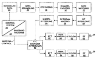
- FIG. 2 is a block diagram of an example base station that might be used to implement some embodiments of the present application
- FIG. 3 is a block diagram of an example mobile terminal that might be used to implement some embodiments of the present application.
- FIG. 4 is a block diagram of an example relay station that might be used to implement some embodiments of the present application.
- FIG. 5 is a block diagram of a logical breakdown of an example OFDM transmitter architecture that might be used to implement some embodiments of the present application;
- FIG. 6 is a block diagram of a logical breakdown of an example OFDM receiver architecture that might be used to implement some embodiments of the present application;
- FIG. 7A is an example SC-FDMA transmitter
- FIG. 7B is an example SC-FDMA receiver
- FIG. 8 is an example Space-Time Block Code (STBC) scheme
- FIG. 9 is an example reference signal arrangement that may be used to support channel estimation.
- FIG. 10 is another example reference signal arrangement that may be used to support channel estimation.
- FIG. 1 shows a base station controller (BSC) 10 which controls wireless communications within multiple cells 12 , which cells are served by corresponding base stations (BS) 14 .
- BSC base station controller
- each cell is further divided into multiple sectors 13 (not shown).
- each base station 14 facilitates communications using OFDM with mobile terminals 16 , which are within the cell 12 associated with the corresponding base station 14 .
- the movement of the mobile terminals 16 in relation to the base stations 14 results in significant fluctuation in channel conditions.
- the base stations 14 and mobile terminals 16 may include multiple antennas to provide spatial diversity for communications.
- relay stations 15 may assist in communications between base stations 14 and mobile terminals 16 .
- Mobile terminals 16 can be handed off 18 from any cell 12 , sector 13 (not shown), base station 14 or relay 15 to an other cell 12 , sector 13 (not shown), base station 14 or relay 15 .
- base stations 14 communicate with each and with another network (such as a core network or the internet, both not shown) over a backhaul network 11 .
- a base station controller 10 is not needed.
- FIG. 2 depicts an example of a base station 14 .
- Base station 14 generally includes a control system 20 , a baseband processor 22 , transmit circuitry 24 , receive circuitry 26 , antennas 28 , and a network interface 30 .
- the receive circuitry 26 receives radio frequency signals bearing information from one or more remote transmitters provided by mobile terminals 16 (illustrated in FIG. 3 ) and relay stations 15 (illustrated in FIG. 4 ).
- a low noise amplifier and a filter may cooperate to amplify and remove broadband interference from the signal for processing.
- Downconversion and digitization circuitry (not shown) will then downconvert the filtered, received signal to an intermediate or baseband frequency signal, which is then digitized into one or more digital streams.
- the baseband processor 22 processes the digitized received signal to extract the information or data bits conveyed in the received signal. This processing typically comprises demodulation, decoding, and error correction operations. As such, the baseband processor 22 is generally implemented in one or more digital signal processors (DSPs) or application-specific integrated circuits (ASICs).
- DSPs digital signal processors
- ASICs application-specific integrated circuits
- baseband processor 22 receives digitized data, which may represent voice, data, or control information, from the network interface 30 under the control of control system 20 , and encodes the data for transmission.
- the encoded data is output to the transmit circuitry 24 , where it is modulated by one or more carrier signals having a desired transmit frequency or frequencies.
- a power amplifier (not shown) will amplify the modulated carrier signals to a level appropriate for transmission, and deliver the modulated carrier signals to the antennas 28 through a matching network (not shown). Modulation and processing details are described in greater detail below.
- FIG. 3 illustrates an example of a mobile terminal 16 .
- the mobile terminal 16 will include a control system 32 , a baseband processor 34 , transmit circuitry 36 , receive circuitry 38 , antennas 40 , and user interface circuitry 42 .
- the receive circuitry 38 receives radio frequency signals bearing information from one or more base stations 14 and relays 15 .
- a low noise amplifier and a filter may cooperate to amplify and remove broadband interference from the signal for processing.
- Downconversion and digitization circuitry (not shown) will then downconvert the filtered, received signal to an intermediate or baseband frequency signal, which is then digitized into one or more digital streams.
- Baseband processor 34 processes the digitized received signal to extract the information or data bits conveyed in the received signal. This processing typically comprises demodulation, decoding, and error correction operations.
- the baseband processor 34 is generally implemented in one or more digital signal processors (DSPs) and application specific integrated circuits (ASICs).
- DSPs digital signal processors
- ASICs application specific integrated circuits
- baseband processor 34 receives digitized data, which may represent voice, video, data, or control information, from the control system 32 , which it encodes for transmission.
- the encoded data is output to the transmit circuitry 36 , where it is used by a modulator to modulate one or more carrier signals that is at a desired transmit frequency or frequencies.
- a power amplifier (not shown) will amplify the modulated carrier signals to a level appropriate for transmission, and deliver the modulated carrier signal to the antennas 40 through a matching network (not shown).
- Various modulation and processing techniques available to those skilled in the art are used for signal transmission between the mobile terminal and the base station, either directly or via the relay station.
- the transmission band is divided into multiple, orthogonal carrier waves. Each carrier wave is modulated according to the digital data to be transmitted. Because OFDM divides the transmission band into multiple carriers, the bandwidth per carrier decreases and the modulation time per carrier increases. Since the multiple carriers are transmitted in parallel, the transmission rate for the digital data, or symbols, on any given carrier is lower than when a single carrier is used.
- OFDM modulation utilizes the performance of an Inverse Fast Fourier Transform (IFFT) on the information to be transmitted.
- FFT Fast Fourier Transform
- the IFFT and FFT are provided by digital signal processing carrying out an Inverse Discrete Fourier Transform (IDFT) and Discrete Fourier Transform (DFT), respectively.
- IDFT Inverse Discrete Fourier Transform
- DFT Discrete Fourier Transform
- the characterizing feature of OFDM modulation is that orthogonal carrier waves are generated for multiple bands within a transmission channel.
- the modulated signals are digital signals having a relatively low transmission rate and capable of staying within their respective bands.
- the individual carrier waves are not modulated directly by the digital signals. Instead, all carrier waves are modulated at once by IFFT processing.
- OFDM is preferably used for at least downlink transmission from the base stations 14 to the mobile terminals 16 .
- the respective antennas can be used for reception and transmission using appropriate duplexers or switches and are so labelled only for clarity.
- OFDM is preferably used for downlink transmission from the base stations 14 to the relays 15 and from relay stations 15 to the mobile terminals 16 .
- FIG. 4 illustrates an example relay station 15 .
- the relay station 15 includes a control system 132 , a baseband processor 134 , transmit circuitry 136 , receive circuitry 138 , antennas 130 , and relay circuitry 142 .
- the relay circuitry 142 enables the relay 14 to assist in communications between a base station 16 and mobile terminals 16 .
- the receive circuitry 138 receives radio frequency signals bearing information from one or more base stations 14 and mobile terminals 16 .
- a low noise amplifier and a filter may cooperate to amplify and remove broadband interference from the signal for processing.
- Downconversion and digitization circuitry (not shown) will then downconvert the filtered, received signal to an intermediate or baseband frequency signal, which is then digitized into one or more digital streams.
- Baseband processor 134 processes the digitized received signal to extract the information or data bits conveyed in the received signal. This processing typically comprises demodulation, decoding, and error correction operations.
- Baseband processor 134 is generally implemented in one or more digital signal processors (DSPs) and application specific integrated circuits (ASICs).
- DSPs digital signal processors
- ASICs application specific integrated circuits
- baseband processor 134 receives digitized data, which may represent voice, video, data, or control information, from control system 132 , which it encodes for transmission.
- the encoded data is output to the transmit circuitry 136 , where it is used by a modulator to modulate one or more carrier signals that is at a desired transmit frequency or frequencies.
- a power amplifier (not shown) will amplify the modulated carrier signals to a level appropriate for transmission, and deliver the modulated carrier signal to the antennas 130 through a matching network (not shown).
- Various modulation and processing techniques available to those skilled in the art are used for signal transmission between the mobile terminal and the base station, either directly or indirectly via a relay station, as described above.
- base station controller 10 will send data to be transmitted to various mobile terminals 16 to base station 14 , either directly or with the assistance of a relay station 15 .
- base station 14 uses the channel quality indicators (CQI) values associated with the mobile terminals to schedule the data for transmission as well as select an appropriate modulation and coding scheme (MCS) level for transmitting the scheduled data.
- CQI values may be received directly from the mobile terminals 16 or determined at the base station 14 based on information provided by the mobile terminals 16 .
- the CQI value associated with each mobile terminal 16 may for example be a function of the signal-to-interference ratio (SIR), as well as of the degree to which the channel amplitude (or response) varies across the OFDM frequency band.
- SIR signal-to-interference ratio
- Scheduled data 44 which is a stream of bits, is scrambled in a manner reducing the peak-to-average power ratio associated with the data using data scrambling logic 46 .
- a cyclic redundancy check (CRC) for the scrambled data is determined and appended to the scrambled data using CRC adding logic 48 .
- channel coding is performed using channel encoder logic 50 to effectively add redundancy to the data to facilitate recovery and error correction at the mobile terminal 16 .
- the channel coding for a particular mobile terminal 16 is based on the current CQI value associated with that mobile terminal.
- the channel encoder logic 50 uses known Turbo encoding techniques.
- the encoded data is then processed by rate matching logic 52 to compensate for the data expansion associated with encoding.
- Bit interleaver logic 54 systematically reorders the bits in the encoded data to minimize the loss of consecutive data bits.
- the resultant data bits are systematically mapped into corresponding symbols depending on the chosen baseband modulation by mapping logic 56 .
- mapping logic 56 Preferably, Quadrature Amplitude Modulation (QAM) or Quadrature Phase Shift Key (QPSK) modulation is used.
- QAM Quadrature Amplitude Modulation
- QPSK Quadrature Phase Shift Key
- the degree of modulation is chosen based on the CQI value for the particular mobile terminal.
- the symbols may be systematically reordered to further bolster the immunity of the transmitted signal to periodic data loss caused by frequency selective fading using symbol interleaver logic 58 .
- STC encoder logic 60 which modifies the symbols in a fashion making the transmitted signals more resistant to interference and more readily decoded at a mobile terminal 16 .
- the STC encoder logic 60 will process the incoming symbols and provide “n” outputs corresponding to the number of transmit antennas 28 for the base station 14 .
- the control system 20 and/or baseband processor 22 as described above with reference to FIG. 5 will provide a mapping control signal to control STC encoding.
- the symbols for the “n” outputs are representative of the data to be transmitted and capable of being recovered by the mobile terminal 16 .
- each of the symbol streams output by the SIC encoder logic 60 is sent to a corresponding IFFT processor 62 , illustrated separately for ease of understanding.
- the IFFT processors 62 will preferably operate on the respective symbols to provide an inverse Fourier Transform.
- the output of the TUFT processors 62 provides symbols in the time domain. The time domain symbols are grouped into frames, which are associated with a prefix by prefix insertion logic 64 .
- Each of the resultant signals is up-converted in the digital domain to an intermediate frequency and converted to an analog signal via the corresponding digital up-conversion (DUG) and digital-to-analog (DIA) conversion circuitry 66 .
- the resultant (analog) signals are then simultaneously modulated at the desired RF frequency, amplified, and transmitted via the RF circuitry 68 and antennas 28 .
- pilot signals known by the intended mobile terminal 16 are scattered among the sub-carriers. The mobile terminal 16 , which is discussed in detail below, will use the pilot signals for channel estimation.
- FIG. 6 illustrate reception of the transmitted signals by a mobile terminal 16 , either directly from base station 14 or with the assistance of relay 15 .
- the respective signals are demodulated and amplified by corresponding RF circuitry 70 .
- Analog-to-digital (AID) converter and down-conversion circuitry 72 digitizes and downconverts the analog signal for digital processing.
- the resultant digitized signal may be used by automatic gain control circuitry (AGC) 74 to control the gain of the amplifiers in the RF circuitry 70 based on the received signal level.
- AGC automatic gain control circuitry
- the digitized signal is provided to synchronization logic 76 , which includes coarse synchronization logic 78 , which buffers several OFDM symbols and calculates an auto-correlation between the two successive OFDM symbols.
- a resultant time index corresponding to the maximum of the correlation result determines a fine synchronization search window, which is used by fine synchronization logic 80 to determine a precise framing starting position based on the headers.
- the output of the fine synchronization logic 80 facilitates frame acquisition by frame alignment logic 84 . Proper framing alignment is important so that subsequent PET processing provides an accurate conversion from the time domain to the frequency domain.
- the fine synchronization algorithm is based on the correlation between the received pilot signals carried by the headers and a local copy of the known pilot data.
- the synchronization logic 76 includes frequency offset and clock estimation logic 82 , which is based on the headers to help estimate such effects on the transmitted signal and provide those estimations to the correction logic 88 to properly process OFDM symbols.
- the OFDM symbols in the time domain are ready for conversion to the frequency domain using EFT processing logic 90 .
- the results are frequency domain symbols, which are sent to processing logic 92 .
- the processing logic 92 extracts the scattered pilot signal using scattered pilot extraction logic 94 , determines a channel estimate based on the extracted pilot signal using channel estimation logic 96 , and provides channel responses for all sub-carriers using channel reconstruction logic 98 .
- the pilot signal is essentially multiple pilot symbols that are scattered among the data symbols throughout the OFDM sub-carriers in a known pattern in both time and frequency.
- the processing logic compares the received pilot symbols with the pilot symbols that are expected in certain sub-carriers at certain times to determine a channel response for the sub-carriers in which pilot symbols were transmitted.
- the results are interpolated to estimate a channel response for most, if not all, of the remaining sub-carriers for which pilot symbols were not provided.
- the actual and interpolated channel responses are used to estimate an overall channel response, which includes the channel responses for most, if not all, of the sub-carriers in the OFDM channel.
- the frequency domain symbols and channel reconstruction information which are derived from the channel responses for each receive path are provided to an STC decoder 100 , which provides STC decoding on both received paths to recover the transmitted symbols.
- the channel reconstruction information provides equalization information to STC decoder 100 sufficient to remove the effects of the transmission channel when processing the respective frequency domain symbols.
- the relay station could act as another base station or as a terminal in the context of this invention.
- the recovered symbols are placed back in order using symbol de-interleaver logic 102 , which corresponds to the symbol interleaver logic 58 of the transmitter.
- the de-interleaved symbols are then demodulated or de-mapped to a corresponding bitstream using dc-mapping logic 104 .
- the bits are then de-interleaved using bit de-interleaver logic 106 , which corresponds to the bit interleaver logic 54 of the transmitter architecture.
- the dc-interleaved bits are then processed by rate dc-matching logic 108 and presented to channel decoder logic 110 to recover the initially scrambled data and the CRC checksum.
- CRC logic 112 removes the CRC checksum, checks the scrambled data in traditional fashion, and provides it to the de-scrambling logic 114 for de-scrambling using the known base station de-scrambling code to recover the originally transmitted data 116 .
- a CQI value is determined and transmitted to the base station 14 .
- the CQI value may be a function of the signal-to-interference ratio (SIR), as well as the degree to which the channel response varies across the various sub-carriers in the OFDM frequency band.
- SIR signal-to-interference ratio
- the channel gain for each sub-carrier in the OFDM frequency band being used to transmit information is compared relative to one another to determine the degree to which the channel gain varies across the OFDM frequency band.
- numerous techniques are available to measure the degree of variation, one technique is to calculate the standard deviation of the channel gain for each sub-carrier throughout the OFDM frequency band being used to transmit data.
- FIGS. 1 to 6 provide one specific example of a communication system that could be used to implement embodiments of the application. It is to be understood that embodiments can be implemented with communications systems having architectures that are different than the specific example, but that operate in a manner consistent with the implementation of the embodiments as described herein.
- the communication system of FIGS. 1 to 6 is 3GPP LTE-compliant, and Single Carrier Frequency-Division Multiple Access (SC-FDMA) is utilized as the multiple-access scheme for uplink transmissions from mobile device 16 to either of relay 15 and base station 14 .
- SC-FDMA Single Carrier Frequency-Division Multiple Access
- FIGS. 7A and 7B illustrate the basic signal processing steps needed at the transmitter and receiver, respectively, for a SC-FDMA channel.
- SC-FDMA can be viewed as a Discrete Fourier Transform (DFT) pre-coded OFDMA scheme.
- DFT Discrete Fourier Transform
- OFDMA transmit circuitry 702 and OFDMA receive circuitry 704 There are several similarities in the overall transceiver processing of SC-FDMA and OFDMA.
- OFDMA transmit circuitry 702 and OFDMA receive circuitry 704 Those common aspects between OFDMA and SC-FDMA are depicted generally as OFDMA transmit circuitry 702 and OFDMA receive circuitry 704 , as they will be obvious to a person having ordinary skill in the art in view of the present specification.
- SC-FDMA is distinctly different from OFDMA because of the DFT pre-coding 703 of the modulated symbols, and the corresponding IDFT 705 of the demodulated symbols. Because of this pre-coding, the SC-FDMA sub
- STBC Space-Time Block Code
- STBC Space-Time Block Code
- PUSCH Physical Uplink Control Channel
- STBC may be used with symbols paired from two consecutive slots. If the symbols have a low PAPR property, then with STBC, the low PAPR is preserved. If after pairing there exists an unpaired symbol (i.e., an orphan symbol), the orphan symbol may be sent using a Cyclic Delay Diversity (CDD) scheme with a large delay.
- CDD Cyclic Delay Diversity
- the delay may be, for example, a quarter of a cycle or three quarters of a cycle. The delay provides implementation simplicity without any performance degradation.
- the delay makes CDD equivalent to a pre-coded MIMO system by providing frequency diversity if the channel conditions change over time.
- the codebook may be of size 4 as already adopted for downlink closed loop MIMO systems. This approach is equivalent to a pre-coding matrix hoping (PMH) scheme, where the precoding matrix changes from one entry in the codebook to another.
- PMH pre-coding matrix hoping
- STBC may be used with symbols paired from two orthogonal sequences.
- the number of symbols in each subframe is even. However, in some cases the number of symbols in each slot is odd. In such cases, the last symbol of slot 0 may be paired with the first symbol of slot 1 . Because the two slots are in different frequency bands, a minimum mean square error (MMSE) receiver may be used for these symbols.
- MMSE minimum mean square error
- FIG. 8 illustrates STBC coding applied to paired symbols from two consecutive low PAPR sequences such that the low PAPR property is preserved. If a pair consisting of two STBC symbols from different slots is transmitted on different frequency bands due to inter-slot hopping, a minimum mean square error (MMSE) receiver may be used. Otherwise, an Alamouti decoder can be used. For example, PUCCH channel formats 2 / 2 a / 2 b may have an odd number of symbols in each slot while having an even number of symbols in each subframe.
- MMSE minimum mean square error
- a pairing operation results in an unpaired symbol, also referred to as an orphan symbol.
- CDD transmit diversity may be used.
- one symbol of the second slot is dedicated for the sounding reference signal (SRS).
- CS cyclic shift
- PMH pre-coding matrix hopping
- PMH can be implemented with low complexity, and performs as well as (or better than) CDD with other CS values.
- a two-level code division multiplexing (CDM) scheme for reference signal (RS) transmission may be used, where the first level separates the UEs (same as supporting only one transmit antenna) and the second level separates the antennas.
- CDM code division multiplexing
- the first level separates the UEs (same as supporting only one transmit antenna) and the second level separates the antennas.
- the block of four RSs is Hadamard coded.
- only one sequence is assigned to each UE at each time.
- the RSs may be transmitted in the middle of each slot in order to reduce the effect of intra-code interference.
- FIG. 9 shows an example RS arrangement for two RSs in the same slot (e.g. PUCCH with normal cyclic prefix (CP) in LTE for format 2 , 2 a and 2 b ).
- Hadamard coded RSs may be transmitted, with both antennas using the same orthogonal sequence (OS) at a given slot.
- the RSs are Hadamard coded across time and space within each slot: at RS 1 , both transmit antennas T ⁇ 1 and T ⁇ 2 transmit sequence S 1 ; at RS 2 , transmit antenna T ⁇ 1 transmits sequence S 1 and transmit antenna T ⁇ 2 transmits sequence ⁇ S 1 .
- FIG. 10 shows another example RS arrangement for two RSs in the same slot.
- the RSs could be put next to each other in the middle of the slot, as shown in FIG. 10 .
- symbols 3 and 4 may be used for RSs in slot 0
- symbols 2 and 3 may be used for RSs in slot 1 . It will be appreciated that by using this approach intra-code interference is suppressed, and better performance can be achieved.
- the proposed two-level CDM RS transmission enables efficient CDM MIMO channel estimation.
- the same number of UEs as the single transmit antenna case may be multiplexed and there is no need to change the existing RS sequence assignment scheme.
- the proposed RS arrangement enables the two-level CDM RS transmission scheme to achieve better performance by suppressing the intra-code interference.
Landscapes
- Engineering & Computer Science (AREA)
- Computer Networks & Wireless Communication (AREA)
- Signal Processing (AREA)
- Mobile Radio Communication Systems (AREA)
- Radio Transmission System (AREA)
Abstract
Description
-
- Physical Broadcast Channel (PBCH): This channel carries system information for user equipments (UEs) requiring access to the network.
- Physical Downlink Control Channel (PDCCH): The main purpose of this physical channel is to carry scheduling information.
- Physical Hybrid ARQ Indicator Channel (PHICH): This channel is used to report the Hybrid ARQ status.
- Physical Downlink Shared Channel (PDSCH): This channel is used for unicast and paging functions.
- Physical Multicast Channel (PMCH): This physical channel carries system information for multicast purposes.
- Physical Control Format Indicator Channel (PCFICH): This channel provides information to enable the UEs to decode the PDSCH.
-
- Physical Uplink Control Channel (PUCCH): This channel is used to transport user signaling data from one or more UE that can transmit on the control channel. The PUCCH transports, for example, acknowledgment responses and retransmission requests, service scheduling requests, and channel quality information measured by the UE to the system.
- Physical Uplink Shared Channel (PUSCH): This channel is used to transport user data from one or more mobiles that can transmit on the shared channel.
- Physical Random Access Channel (PRACH): This uplink physical channel allows a mobile to randomly transmit access requests when the mobile attempts to access the wireless communication system.
Claims (14)
Priority Applications (1)
| Application Number | Priority Date | Filing Date | Title |
|---|---|---|---|
| US13/394,888 US8982997B2 (en) | 2009-09-21 | 2010-09-21 | Signaling and channel estimation for uplink transmit diversity |
Applications Claiming Priority (3)
| Application Number | Priority Date | Filing Date | Title |
|---|---|---|---|
| US24412609P | 2009-09-21 | 2009-09-21 | |
| PCT/CA2010/001509 WO2011032297A1 (en) | 2009-09-21 | 2010-09-21 | Signaling and channel estimation for uplink transmit diversity |
| US13/394,888 US8982997B2 (en) | 2009-09-21 | 2010-09-21 | Signaling and channel estimation for uplink transmit diversity |
Publications (2)
| Publication Number | Publication Date |
|---|---|
| US20120307928A1 US20120307928A1 (en) | 2012-12-06 |
| US8982997B2 true US8982997B2 (en) | 2015-03-17 |
Family
ID=43758007
Family Applications (1)
| Application Number | Title | Priority Date | Filing Date |
|---|---|---|---|
| US13/394,888 Active 2031-06-25 US8982997B2 (en) | 2009-09-21 | 2010-09-21 | Signaling and channel estimation for uplink transmit diversity |
Country Status (9)
| Country | Link |
|---|---|
| US (1) | US8982997B2 (en) |
| EP (1) | EP2481248A4 (en) |
| JP (1) | JP5702387B2 (en) |
| KR (1) | KR101710616B1 (en) |
| CN (1) | CN102812763B (en) |
| BR (1) | BR112012006378A2 (en) |
| CA (1) | CA2773790C (en) |
| RU (1) | RU2518509C2 (en) |
| WO (1) | WO2011032297A1 (en) |
Cited By (3)
| Publication number | Priority date | Publication date | Assignee | Title |
|---|---|---|---|---|
| US20160233984A1 (en) * | 2013-09-26 | 2016-08-11 | Hitachi Kokusai Electric Inc. | Wireless communication system and transmitter |
| US10027428B2 (en) * | 2016-01-25 | 2018-07-17 | Innowireless Co., Ltd. | Method of calibrating power for MIMO-OFDM transmitter |
| US10038488B2 (en) | 2016-12-22 | 2018-07-31 | Qualcomm Incorporated | PUCCH transmit diversity with one-symbol STBC |
Families Citing this family (19)
| Publication number | Priority date | Publication date | Assignee | Title |
|---|---|---|---|---|
| KR101498297B1 (en) * | 2008-11-23 | 2015-03-05 | 엘지전자 주식회사 | Method for transmitting data in a wireless communication system |
| KR20110037422A (en) * | 2009-10-06 | 2011-04-13 | 주식회사 팬택 | Method and device for relaying uplink signal |
| CN102014510B (en) * | 2009-11-03 | 2015-02-25 | 电信科学技术研究院 | Method, equipment and system of uplink control channel resource allocation |
| CN103229532B (en) * | 2011-02-25 | 2016-04-20 | 夏普株式会社 | Wireless communication system, base station apparatus and wireless communications path system of selection |
| CN104038320B (en) * | 2013-03-04 | 2019-03-01 | 中兴通讯股份有限公司 | Resource impact, method of reseptance and device signal, acquisition methods and device |
| CN103338508B (en) * | 2013-07-10 | 2015-09-16 | 武汉邮电科学研究院 | A kind of associating frequency deviation estimating method and system |
| US10285160B2 (en) * | 2013-10-31 | 2019-05-07 | Lg Electronics Inc. | Broadcast channel transmitting method through massive MIMO in wireless communication system and apparatus therefor |
| CN110429962B (en) | 2014-01-29 | 2021-12-14 | 华为技术有限公司 | Uplink access method, device and system |
| US9184967B1 (en) * | 2014-09-30 | 2015-11-10 | Texas Instruments Incorporated | System and method for generating frame structure for MIMO narrowband power line communications |
| EP3217662B1 (en) | 2014-11-27 | 2019-08-21 | Huawei Technologies Co., Ltd. | Rate matching method and apparatus for polar code, and wireless communication device |
| US10126421B2 (en) * | 2015-05-15 | 2018-11-13 | Maxlinear, Inc. | Dynamic OFDM symbol shaping for radar applications |
| US10404280B2 (en) | 2015-11-19 | 2019-09-03 | Westhold Corporation | Error correction using cyclic code-based LDPC codes |
| CN105681787B (en) * | 2016-01-22 | 2019-01-18 | 北京大学 | The method and apparatus that space-time signal is encoded |
| US11228758B2 (en) | 2016-01-22 | 2022-01-18 | Peking University | Imaging method and device |
| US10237105B2 (en) * | 2017-01-08 | 2019-03-19 | Qualcomm Incorporated | Multiplexing uplink transmissions with transmit diversity with single carrier waveform |
| US11212151B2 (en) * | 2017-08-23 | 2021-12-28 | Qualcomm Incorporated | User multiplexing for uplink control information |
| US10484228B2 (en) * | 2018-03-05 | 2019-11-19 | Qualcomm Incorporated | Wakeup radio transmit diversity |
| EP3832924A4 (en) * | 2018-08-03 | 2022-03-09 | NTT DoCoMo, Inc. | User terminal and radio communication method |
| JP7595065B2 (en) | 2019-08-05 | 2024-12-05 | シュアー アクイジッション ホールディングス インコーポレイテッド | Transmitting antenna diversity wireless audio system |
Citations (12)
| Publication number | Priority date | Publication date | Assignee | Title |
|---|---|---|---|---|
| US20040082356A1 (en) | 2002-10-25 | 2004-04-29 | Walton J. Rodney | MIMO WLAN system |
| EP1596520A2 (en) | 2004-05-12 | 2005-11-16 | Kabushiki Kaisha Toshiba | Spatial division multiplexing for MIMO devices |
| US20050254596A1 (en) | 2004-05-17 | 2005-11-17 | Naguib Ayman F | Space-time block coding in orthogonal frequency division communication systems |
| US20060077886A1 (en) * | 2004-10-13 | 2006-04-13 | Samsung Electronics Co., Ltd. | Transmission apparatus and method for a base station using block coding and cyclic delay diversity techniques in an OFDM mobile communication system |
| WO2007081977A2 (en) | 2006-01-11 | 2007-07-19 | Interdigital Technology Corporation | Method and apparatus for implementing space time processing with unequal modulation and coding schemes |
| WO2007095102A1 (en) | 2006-02-10 | 2007-08-23 | Interdigital Technology Corporation | Method and apparatus for performing uplink transmission in a multiple-input multiple-output single carrier frequency division multiple access system |
| WO2009055208A1 (en) | 2007-10-22 | 2009-04-30 | Applied Materials, Inc. | Process testers and testing methodology for thin-film photovoltaic devices |
| WO2009066208A2 (en) | 2007-11-20 | 2009-05-28 | Koninklijke Philips Electronics N.V. | Data transmission network |
| US20100041350A1 (en) * | 2008-08-13 | 2010-02-18 | Samsung Electronics, Co., Ltd. | Uplink transmissions with two antenna ports |
| WO2010032953A2 (en) | 2008-09-17 | 2010-03-25 | Samsung Electronics Co., Ltd. | Apparatus and method for transmit diversity schemes |
| US20100208680A1 (en) | 2009-02-13 | 2010-08-19 | Samsung Electronics Co., Ltd. | Apparatus and method for codeword to layer mapping in mimo transmission wireless systems |
| US20110143696A1 (en) * | 2009-06-18 | 2011-06-16 | Qualcomm Incorporated | Pusch transmit delivery scheme selection |
Family Cites Families (10)
| Publication number | Priority date | Publication date | Assignee | Title |
|---|---|---|---|---|
| GB2423675B (en) * | 2005-02-28 | 2009-08-19 | King S College London | Diversity transmitter and method |
| US20070147543A1 (en) * | 2005-12-22 | 2007-06-28 | Samsung Electronics Co., Ltd. | Extension of space-time block code for transmission with more than two transmit antennas |
| CN101379748A (en) * | 2006-02-10 | 2009-03-04 | 交互数字技术公司 | Method and apparatus for performing uplink transmission in a multiple-input multiple-output single carrier frequency division multiple access system |
| EP3001578B1 (en) * | 2006-08-07 | 2017-03-29 | InterDigital Technology Corporation | Method, apparatus and system for implementing multi-user virtual multiple-input multiple-output |
| JP5044165B2 (en) * | 2006-08-14 | 2012-10-10 | 株式会社東芝 | Transmitter, receiver and method in a multi-antenna wireless communication system |
| JP4762203B2 (en) * | 2007-06-29 | 2011-08-31 | 株式会社東芝 | OFDM signal transmission method, OFDM transmitter and OFDM receiver |
| JP5032666B2 (en) * | 2007-10-22 | 2012-09-26 | テレフオンアクチーボラゲット エル エム エリクソン(パブル) | How to configure a small cell radio base station |
| CN101471755B (en) * | 2007-12-24 | 2011-08-24 | 联想(北京)有限公司 | Transmitter and signal transmission method |
| JP2009194853A (en) * | 2008-02-18 | 2009-08-27 | Kyocera Corp | Wireless communication apparatus and wireless communication method. |
| US8537790B2 (en) * | 2008-03-10 | 2013-09-17 | Motorola Mobility Llc | Hierarchical pilot structure in wireless communication systems |
-
2010
- 2010-09-21 US US13/394,888 patent/US8982997B2/en active Active
- 2010-09-21 BR BR112012006378A patent/BR112012006378A2/en not_active IP Right Cessation
- 2010-09-21 CA CA2773790A patent/CA2773790C/en active Active
- 2010-09-21 RU RU2012110924/07A patent/RU2518509C2/en active
- 2010-09-21 JP JP2012529083A patent/JP5702387B2/en active Active
- 2010-09-21 KR KR1020127010251A patent/KR101710616B1/en active Active
- 2010-09-21 WO PCT/CA2010/001509 patent/WO2011032297A1/en active Application Filing
- 2010-09-21 CN CN201080052595.5A patent/CN102812763B/en active Active
- 2010-09-21 EP EP10816543.2A patent/EP2481248A4/en not_active Withdrawn
Patent Citations (14)
| Publication number | Priority date | Publication date | Assignee | Title |
|---|---|---|---|---|
| RU2321951C2 (en) | 2002-10-25 | 2008-04-10 | Квэлкомм Инкорпорейтед | Method for processing spatial distribution for multi-antenna communication system |
| US20040082356A1 (en) | 2002-10-25 | 2004-04-29 | Walton J. Rodney | MIMO WLAN system |
| EP1596520A2 (en) | 2004-05-12 | 2005-11-16 | Kabushiki Kaisha Toshiba | Spatial division multiplexing for MIMO devices |
| US20050254596A1 (en) | 2004-05-17 | 2005-11-17 | Naguib Ayman F | Space-time block coding in orthogonal frequency division communication systems |
| RU2344555C2 (en) | 2004-05-17 | 2009-01-20 | Квэлкомм Инкорпорейтед | Spatial-temporal block coding in communication systems with orthogonal frequency-dividing channeling |
| US20060077886A1 (en) * | 2004-10-13 | 2006-04-13 | Samsung Electronics Co., Ltd. | Transmission apparatus and method for a base station using block coding and cyclic delay diversity techniques in an OFDM mobile communication system |
| WO2007081977A2 (en) | 2006-01-11 | 2007-07-19 | Interdigital Technology Corporation | Method and apparatus for implementing space time processing with unequal modulation and coding schemes |
| WO2007095102A1 (en) | 2006-02-10 | 2007-08-23 | Interdigital Technology Corporation | Method and apparatus for performing uplink transmission in a multiple-input multiple-output single carrier frequency division multiple access system |
| WO2009055208A1 (en) | 2007-10-22 | 2009-04-30 | Applied Materials, Inc. | Process testers and testing methodology for thin-film photovoltaic devices |
| WO2009066208A2 (en) | 2007-11-20 | 2009-05-28 | Koninklijke Philips Electronics N.V. | Data transmission network |
| US20100041350A1 (en) * | 2008-08-13 | 2010-02-18 | Samsung Electronics, Co., Ltd. | Uplink transmissions with two antenna ports |
| WO2010032953A2 (en) | 2008-09-17 | 2010-03-25 | Samsung Electronics Co., Ltd. | Apparatus and method for transmit diversity schemes |
| US20100208680A1 (en) | 2009-02-13 | 2010-08-19 | Samsung Electronics Co., Ltd. | Apparatus and method for codeword to layer mapping in mimo transmission wireless systems |
| US20110143696A1 (en) * | 2009-06-18 | 2011-06-16 | Qualcomm Incorporated | Pusch transmit delivery scheme selection |
Non-Patent Citations (2)
| Title |
|---|
| International Search Report mailed Jan. 6, 2011, in relation to PCT Patent Application No. PCT/CA2010/001509. |
| Written Opinion mailed Jan. 6, 2011, in relation to PCT Patent Application No. PCT/CA2010/001509. |
Cited By (5)
| Publication number | Priority date | Publication date | Assignee | Title |
|---|---|---|---|---|
| US20160233984A1 (en) * | 2013-09-26 | 2016-08-11 | Hitachi Kokusai Electric Inc. | Wireless communication system and transmitter |
| US9716568B2 (en) * | 2013-09-26 | 2017-07-25 | Hitachi Kokusai Electric Inc. | Wireless communication system and transmitter |
| US10027428B2 (en) * | 2016-01-25 | 2018-07-17 | Innowireless Co., Ltd. | Method of calibrating power for MIMO-OFDM transmitter |
| US10038488B2 (en) | 2016-12-22 | 2018-07-31 | Qualcomm Incorporated | PUCCH transmit diversity with one-symbol STBC |
| US10171155B2 (en) | 2016-12-22 | 2019-01-01 | Qualcomm Incorporated | PUCCH transmit diversity with one-symbol STBC |
Also Published As
| Publication number | Publication date |
|---|---|
| WO2011032297A1 (en) | 2011-03-24 |
| EP2481248A1 (en) | 2012-08-01 |
| JP2013505604A (en) | 2013-02-14 |
| KR101710616B1 (en) | 2017-02-27 |
| US20120307928A1 (en) | 2012-12-06 |
| CN102812763A (en) | 2012-12-05 |
| CN102812763B (en) | 2015-04-15 |
| EP2481248A4 (en) | 2017-07-05 |
| KR20130084594A (en) | 2013-07-25 |
| CA2773790C (en) | 2017-05-16 |
| RU2518509C2 (en) | 2014-06-10 |
| BR112012006378A2 (en) | 2017-02-21 |
| JP5702387B2 (en) | 2015-04-15 |
| RU2012110924A (en) | 2013-10-27 |
| CA2773790A1 (en) | 2011-03-24 |
Similar Documents
| Publication | Publication Date | Title |
|---|---|---|
| US8982997B2 (en) | Signaling and channel estimation for uplink transmit diversity | |
| JP5579182B2 (en) | Enabling downlink transparent relay in wireless communication networks | |
| US9622229B2 (en) | Network relay signaling for downlink transparent relay | |
| US8687480B2 (en) | Systems and methods for SC-FDMA transmission diversity | |
| US9036663B2 (en) | Method and system for space code transmit diversity of PUCCH | |
| US8731087B2 (en) | Uplink MIMO transmission from mobile communications devices | |
| US20110206157A1 (en) | Reference signal design for downlink high-order mimo | |
| WO2011047462A2 (en) | Reference signal design for downlink high-order mimo | |
| CA2774723C (en) | Network-relay signaling for downlink transparent relay | |
| KR20120065319A (en) | Apparatus and method for signalling active assignments to a group of wireless stations | |
| US20110069682A1 (en) | Ranging channel structures and methods | |
| US20110280336A1 (en) | Enhanced Method for Transmitting or Retransmitting Packets | |
| US20110255630A1 (en) | Enhanced MBS for OFDM Systems |
Legal Events
| Date | Code | Title | Description |
|---|---|---|---|
| AS | Assignment |
Owner name: NORTEL NETWORKS LIMITED, CANADA Free format text: ASSIGNMENT OF ASSIGNORS INTEREST;ASSIGNOR:MAHALLEH, MASOUD EBRAHIMI TAZEH;REEL/FRAME:029014/0671 Effective date: 20120512 Owner name: NORTEL NETWORKS LIMITED, CANADA Free format text: ASSIGNMENT OF ASSIGNORS INTEREST;ASSIGNOR:JIA, MING;REEL/FRAME:029014/0447 Effective date: 20120510 Owner name: NORTEL NETWORKS LIMITED, CANADA Free format text: ASSIGNMENT OF ASSIGNORS INTEREST;ASSIGNOR:BALIGH, MOHAMMADHADI;REEL/FRAME:029014/0735 Effective date: 20120716 Owner name: NORTEL NETWORKS LIMITED, CANADA Free format text: ASSIGNMENT OF ASSIGNORS INTEREST;ASSIGNOR:MA, JIANGLEI;REEL/FRAME:029014/0824 Effective date: 20120516 Owner name: NORTEL NETWORKS LIMITED, CANADA Free format text: ASSIGNMENT OF ASSIGNORS INTEREST;ASSIGNOR:XU, HUA;REEL/FRAME:029014/0799 Effective date: 20120411 Owner name: NORTEL NETWORKS LIMITED, CANADA Free format text: ASSIGNMENT OF ASSIGNORS INTEREST;ASSIGNOR:KHANDANI, AMIR;REEL/FRAME:029014/0858 Effective date: 20120801 |
|
| FEPP | Fee payment procedure |
Free format text: PAYOR NUMBER ASSIGNED (ORIGINAL EVENT CODE: ASPN); ENTITY STATUS OF PATENT OWNER: LARGE ENTITY |
|
| STCF | Information on status: patent grant |
Free format text: PATENTED CASE |
|
| MAFP | Maintenance fee payment |
Free format text: PAYMENT OF MAINTENANCE FEE, 4TH YEAR, LARGE ENTITY (ORIGINAL EVENT CODE: M1551); ENTITY STATUS OF PATENT OWNER: LARGE ENTITY Year of fee payment: 4 |
|
| MAFP | Maintenance fee payment |
Free format text: PAYMENT OF MAINTENANCE FEE, 8TH YEAR, LARGE ENTITY (ORIGINAL EVENT CODE: M1552); ENTITY STATUS OF PATENT OWNER: LARGE ENTITY Year of fee payment: 8 |